PV Introduction guide for electricians PV/Technical/PV... · systems. This Guide is not...
12
Solar PV General Introduction Guide for Electricians Version August 2013 Solar Group Limited 09 477 2999 solargroup.co.nz Solar PV General Introduction Guide for Electricians Important Note: This guide was written to provide a broad guidance for electricians that would like to expand their product knowledge and skills for installation of Grid-connected PV Solar systems. This Guide is not comprehensive enough to cover specific aspects or a specific job This guide covers only the electrical aspects of PV not the mechanical ones
Transcript of PV Introduction guide for electricians PV/Technical/PV... · systems. This Guide is not...

Solar PV General Introduction Guide for Electricians Version August 2013
Solar Group Limited 09 477 2999 solargroup.co.nz
Solar PV General Introduction Guide for
Electricians
Important Note:
This guide was written to provide a broad guidance for electricians that would like to
expand their product knowledge and skills for installation of Grid-connected PV Solar
systems.
This Guide is not comprehensive enough to cover specific aspects or a specific job
This guide covers only the electrical aspects of PV not the mechanical ones
Solar PV General Introduction Guide for Electricians Version August 2013
Solar Group Limited 09 477 2999 solargroup.co.nz
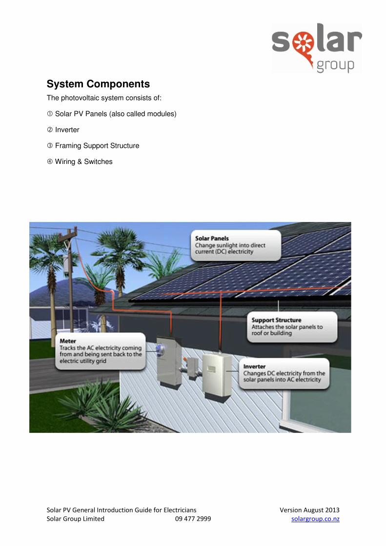
System Components
The photovoltaic system consists of:
Solar PV Panels (also called modules)
Inverter
Framing Support Structure
Wiring & Switches
Solar PV General Introduction Guide for Electricians Version August 2013
Solar Group Limited 09 477 2999 solargroup.co.nz
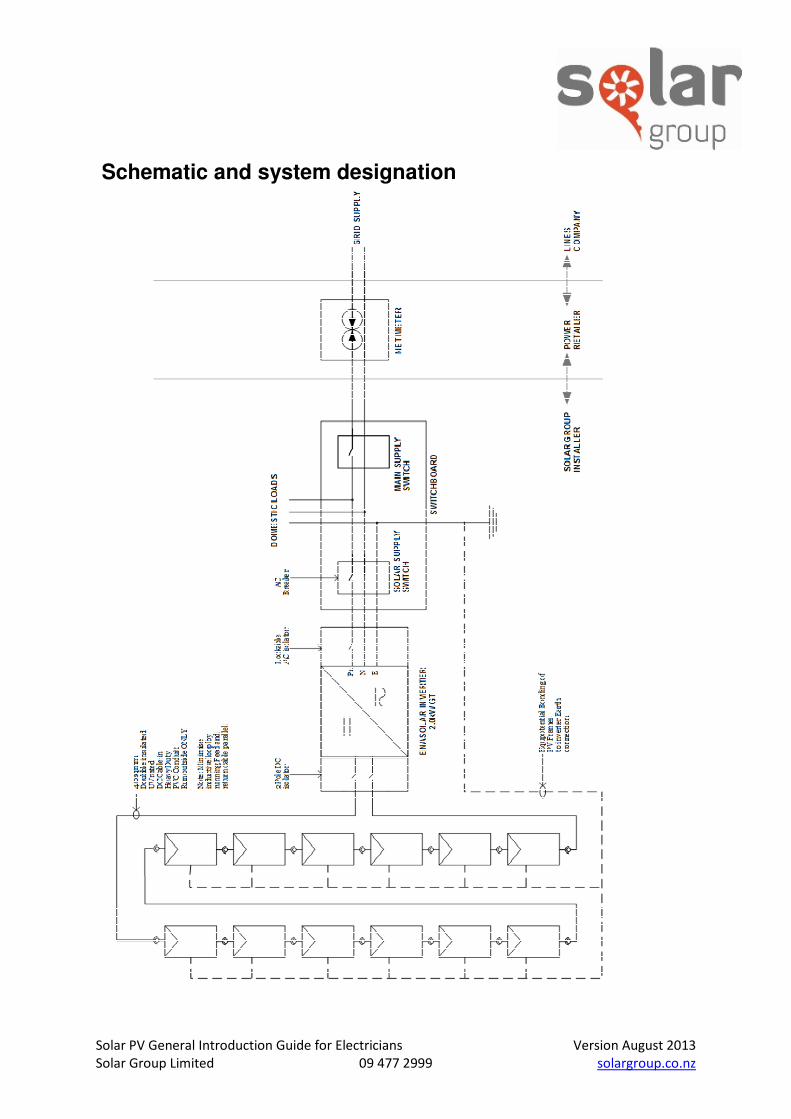
Schematic and system designation
Solar PV General Introduction Guide for Electricians Version August 2013
Solar Group Limited 09 477 2999 solargroup.co.nz
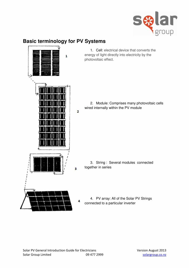
Basic terminology for PV Systems
1. Cell: electrical device that converts the
energy of light directly into electricity by the
photovoltaic effect.
2. Module: Comprises many photovoltaic cells
wired internally within the PV module
3. String : Several modules connected
together in series
4. PV array: All of the Solar PV Strings
connected to a particular inverter
Solar PV General Introduction Guide for Electricians Version August 2013
Solar Group Limited 09 477 2999 solargroup.co.nz
Essential Points relevant to regulations
Dealing with PV means dealing with DC power, system voltages can
be up to 600V DC on domestic systems, and even greater on larger
commercial systems.
Please read all instructions carefully, including the Solar Group
complete solar PV installation manual, before installing and
operating the Photovoltaic unit..
The following standards and regulations Apply Within New Zealand:
AS/NZS 3000 – Wiring Rules
All PV array system bonding conductors shall comply with the material, type, insulation, Identification; installation and connection requirements specified in AS/NZS 3000 but shall not have a cross-sectional area less than 4mm². Reference - AS/NZS 3000:2007 Clause 5.6.3.2
Where the solar supply is connected to a sub-board the protective earth between the main switchboard and sub-board may be of a cross-sectional area less than 4mm². Reference – ruling from EL 001 committee - AS/NZS 3000:2007
Are the conductors installed between the PV array and the main switchboard classified as consumer’s mains? Yes – the conductors between the output terminals of an electricity generating system that provides another source of electrical energy within the installation and the switchboard where they connect are consumers mains. Consumers mains - those conductors between the point of supply and the main switchboard. Reference – AS/NZS 3000:2007 Clause 1.4.33
Point of supply - the junction of the consumers mains with— a) conductors of an electricity distribution system; or b) output terminals of an electricity generating system within the premises. Reference – AS/NZS 3000:2007 Clause 1.4.75
AS/NZS 4777.1 - Grid connection of energy systems via Inverters –Installation requirements AS/NZS 4777.2 - Grid connection of energy systems via Inverters –Inverter requirements AS/NZS 4777.3 - Grid connection of energy systems via Inverters –Grid protection requirements The inverter energy system shall be connected by fixed wiring to a dedicated circuit on a switchboard. The inverter energy system should be connected directly to the main switchboard. In installations where this is not possible or not desirable, the inverter energy system should be connected to the distribution board located physically nearest the inverter, and the main switchboard. All intermediate distribution boards shall be appropriately labelled in accordance with Clause 5.5 of AS/NZS 4777.1.

Solar PV General Introduction Guide for Electricians Version August 2013
Solar Group Limited 09 477 2999 solargroup.co.nz
All the cables between the inverter energy system and any switchboard and all the cables between any distribution boards and a main switchboard which carry current from the inverter energy system shall be rated for at least the full output current of the inverter energy system and, if the inverter energy system is configured as a UPS, for at least the full input current of the inverter energy system. Reference AS/NZS 4777.1 -2005 Clause 5.3.2
AS/NZS 5033 2012 - Installation and safety requirements for photovoltaic (PV) arrays
PV array cables shall be clearly identified so they cannot be mistaken for other power cables within the installation. The cross-sectional area of the DC cable shall be a minimum of 4mm² and rated at the appropriate voltage. Note: Where PV array cabling could be confused with other wiring systems, appropriate identification shall be provided at regular intervals (typically, identification should be not more than 3m
apart).
Cable size - the minimum cable sizes for PV array wiring, based on current carrying capacity, shall be based upon a current rating calculated from Table 3.1 of AS/NZS 5033. NOTE: When calculating cable size, consideration needs to be given to; (a) voltage drop (a maximum of 5% is recommended); and (b) de-rating of the current carrying capacity of a cable due to temperature.
PV array functional earthing PV module and mounting frame earth connections are to be a purpose-made fitting providing earthing or bonding connections or purpose-made penetrating washers or equivalent between the PV modules and mounting frame for the connection of dissimilar metals purpose-made fittings are installed to manufacturer’s instructions (clause 4.4.2.2). Cable lugs, earthing termination and bonding cables are to be fixed by stainless steel bolts, washers and penetrating washers to aluminium frames (clause 4.4.2.2) Connection to earth is at a single point, connected to the main earthing terminal of the electrical installation. This connection point is between the PV array disconnection device and the PCE and as close as possible to or located inside the PCE (clause 4.4.3.1) the PV system functional earthing conductor has the same rating as the earth fault interrupter EFI (clause 4.4.3.2) AS/NZS 3008.1.1:2009 Electrical Installations-Selection of cables
Do not attempt to fix the solar PV panel
Solar PV General Introduction Guide for Electricians Version August 2013
Solar Group Limited 09 477 2999 solargroup.co.nz
Sequence of Work
1. Get a pre-approval from Line Company
2. Get a pre-approval from Power Retailer to commit installation of smart meter
3. Obtain a site-specific PS1 for the mechanical fixing of the panels
4. Install the fixing rails to the roof structure (normally done by builder)
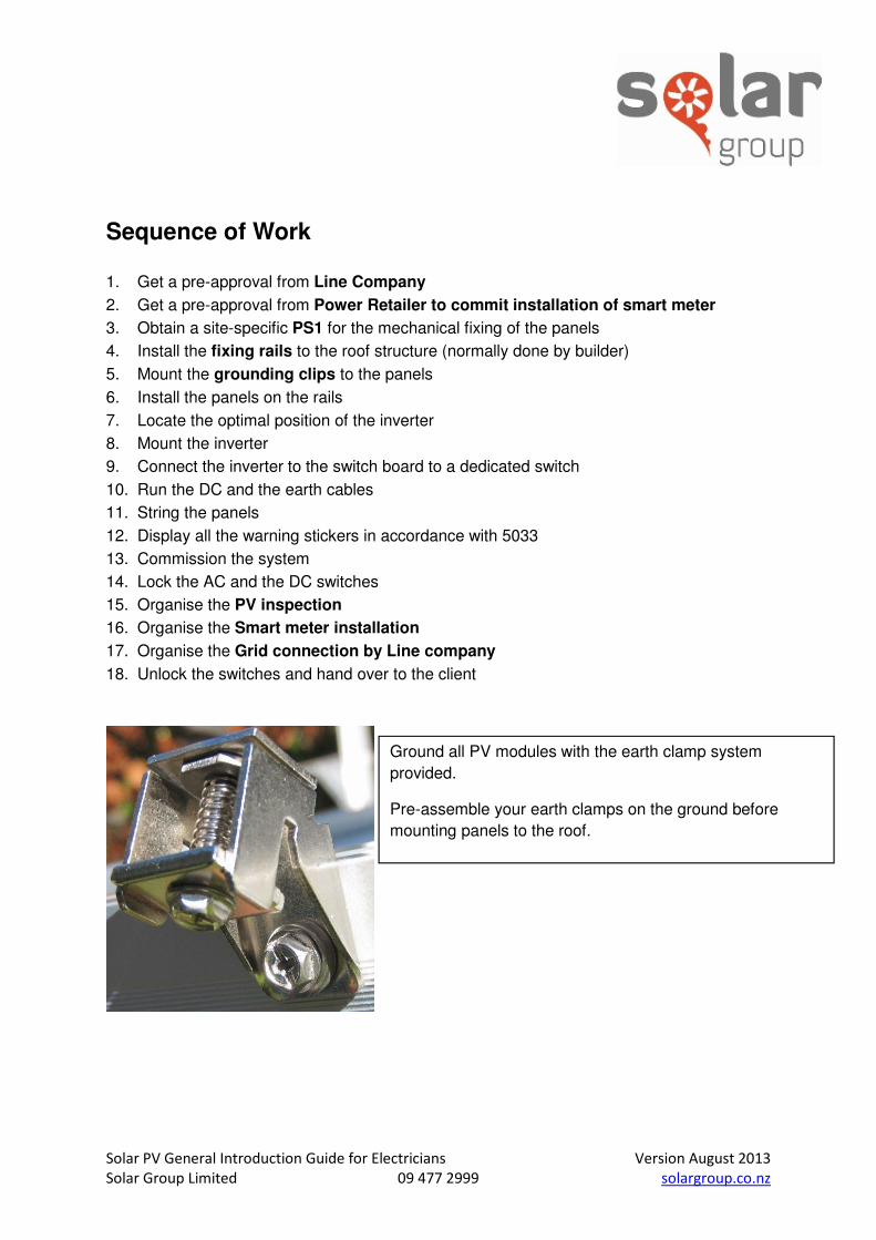
5. Mount the grounding clips to the panels
6. Install the panels on the rails
7. Locate the optimal position of the inverter
8. Mount the inverter
9. Connect the inverter to the switch board to a dedicated switch
10. Run the DC and the earth cables
11. String the panels
12. Display all the warning stickers in accordance with 5033
13. Commission the system
14. Lock the AC and the DC switches
15. Organise the PV inspection
16. Organise the Smart meter installation
17. Organise the Grid connection by Line company
18. Unlock the switches and hand over to the client
Ground all PV modules with the earth clamp system
provided.
Pre-assemble your earth clamps on the ground before
mounting panels to the roof.

Solar PV General Introduction Guide for Electricians Version August 2013
Solar Group Limited 09 477 2999 solargroup.co.nz
Equipment you will need Paper Site Plan and building layout Electrical Diagram Safety sheet and hazard identification Electrical Multi-meter
Mega (MΩ meter) MC4-connector crimping tool Tools Power drill 5.4mm Pilot drill (Or 5.0mm or 6.0mm as substitute) Philips screwdriver HEX socket female drive attachment, 8mm across corners Spanner 14mm between faces Allen keyset Ratchet and socket set Wire cutters, and cable splitters Spool of string for laying out Measuring tape and marking out string Consumables Silicone Sealant Safety equipment Hard hat Non-slip boots Eye protection High visibility clothing Fall restraint system Harness Scaffolding
Solar PV General Introduction Guide for Electricians Version August 2013
Solar Group Limited 09 477 2999 solargroup.co.nz
Wiring Principals All wiring must be carried out in accordance with standards AS/NZS 3000 and AS/NZS 5033,
as per supplied drawings, and by suitably qualified technicians.
Wire size is critical as undersized wiring can lead to significant power losses and a reduction in
system efficiency.
Use outdoor rated wiring if the inverter is installed outside.
4.0mm2 DC Solar Conduit is provided with this system. For strings longer than 60 meter, or
larger systems outside of the Solar Group standard residential systems range, or for
systems with longer cable runs, a larger cable size may be specified by the design engineer.
Voltage losses along the DC cables shall be less than 4%
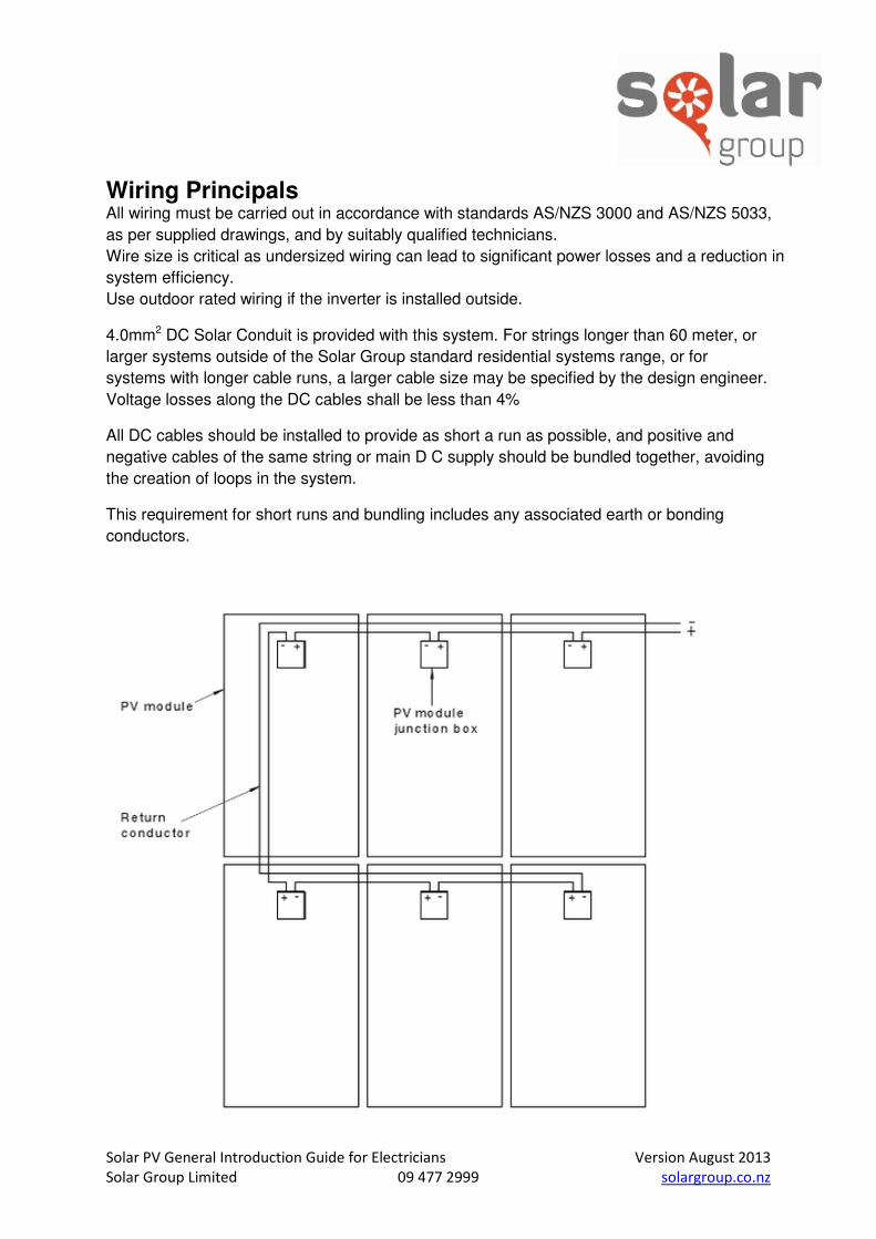
All DC cables should be installed to provide as short a run as possible, and positive and
negative cables of the same string or main D C supply should be bundled together, avoiding
the creation of loops in the system.
This requirement for short runs and bundling includes any associated earth or bonding
conductors.
Solar PV General Introduction Guide for Electricians Version August 2013
Solar Group Limited 09 477 2999 solargroup.co.nz
Conduit Conduit and conduit fixings are supplied to by the installer according to the wiring
requirements for the site.
All conduits must be properly sized to the correct PV array:
20mm conduit: Suitable for DC positive, negative, and earth cable
25mm conduit: Suitable for DC 2 x positive, 2 x negative, and earth cable
Internal cable runs longer than 300mm must be installed in earthed metal conduit or trunking
or be heavy duty type rated to 75’C and be clearly marked. If using a metal conduit it must
be earthed at the inverter, and left electrically floating at the array.
Long cables (eg PV main DC cables over about 50m) should also be installed in earthed
metal conduit or trunking.
External conduit must be heavy duty, suitable for outdoors, and UV rated
All conduits should be labelled “SOLAR” at the conduit terminations.
Be aware of the need to allow any water or condensation that may accumulate in the conduit
or trucking to escape through properly designed and installed vents.
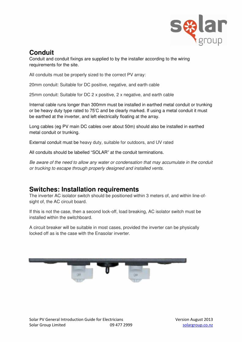
Switches: Installation requirements The inverter AC isolator switch should be positioned within 3 meters of, and within line-of-
sight of, the AC circuit board.
If this is not the case, then a second lock-off, load breaking, AC isolator switch must be
installed within the switchboard.
A circuit breaker will be suitable in most cases, provided the inverter can be physically
locked off as is the case with the Enasolar inverter.
Solar PV General Introduction Guide for Electricians Version August 2013
Solar Group Limited 09 477 2999 solargroup.co.nz
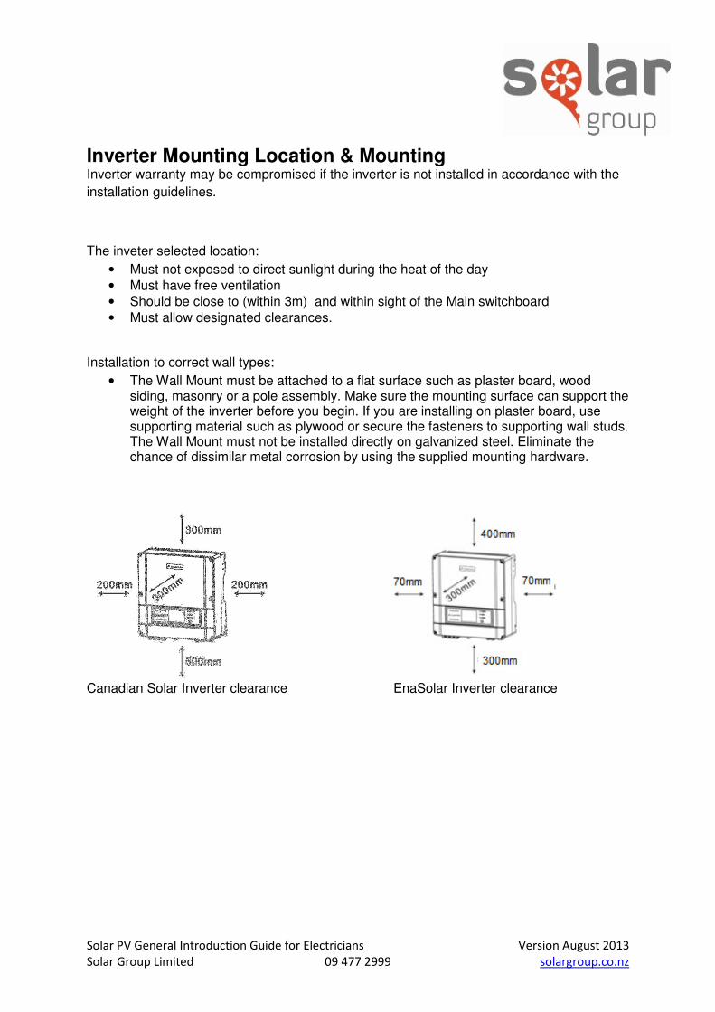
Inverter Mounting Location & Mounting Inverter warranty may be compromised if the inverter is not installed in accordance with the
installation guidelines.
The inveter selected location:
• Must not exposed to direct sunlight during the heat of the day
• Must have free ventilation
• Should be close to (within 3m) and within sight of the Main switchboard
• Must allow designated clearances.
Installation to correct wall types:
• The Wall Mount must be attached to a flat surface such as plaster board, wood siding, masonry or a pole assembly. Make sure the mounting surface can support the weight of the inverter before you begin. If you are installing on plaster board, use supporting material such as plywood or secure the fasteners to supporting wall studs. The Wall Mount must not be installed directly on galvanized steel. Eliminate the chance of dissimilar metal corrosion by using the supplied mounting hardware.
Canadian Solar Inverter clearance EnaSolar Inverter clearance
Solar PV General Introduction Guide for Electricians Version August 2013
Solar Group Limited 09 477 2999 solargroup.co.nz
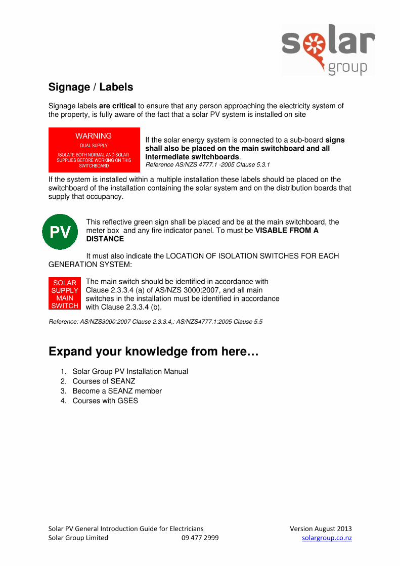
Signage / Labels Signage labels are critical to ensure that any person approaching the electricity system of the property, is fully aware of the fact that a solar PV system is installed on site
If the solar energy system is connected to a sub-board signs shall also be placed on the main switchboard and all intermediate switchboards. Reference AS/NZS 4777.1 -2005 Clause 5.3.1
If the system is installed within a multiple installation these labels should be placed on the switchboard of the installation containing the solar system and on the distribution boards that supply that occupancy.
This reflective green sign shall be placed and be at the main switchboard, the meter box and any fire indicator panel. To must be VISABLE FROM A DISTANCE It must also indicate the LOCATION OF ISOLATION SWITCHES FOR EACH
GENERATION SYSTEM: The main switch should be identified in accordance with Clause 2.3.3.4 (a) of AS/NZS 3000:2007, and all main switches in the installation must be identified in accordance with Clause 2.3.3.4 (b).
Reference: AS/NZS3000:2007 Clause 2.3.3.4,: AS/NZS4777.1:2005 Clause 5.5
Expand your knowledge from here…
1. Solar Group PV Installation Manual
2. Courses of SEANZ
3. Become a SEANZ member
4. Courses with GSES