Pushover Analysis of a Torsionally Eccentric Cellular...
69
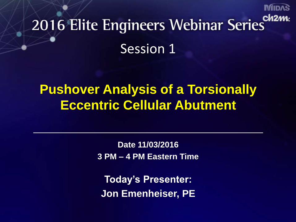
Session 1 Pushover Analysis of a Torsionally Eccentric Cellular Abutment Date 11/03/2016 3 PM – 4 PM Eastern Time Today’s Presenter: Jon Emenheiser, PE
Transcript of Pushover Analysis of a Torsionally Eccentric Cellular...
Session 1
Pushover Analysis of a Torsionally
Eccentric Cellular Abutment
Date 11/03/2016
3 PM – 4 PM Eastern Time
Today’s Presenter:
Jon Emenheiser, PE

This presentation is protected by US and International Copyright laws.
Reproduction, distribution, display and use of the presentation without written
permission of the speaker is prohibited.
© Midasoft Inc., 2016
Copyright Materials
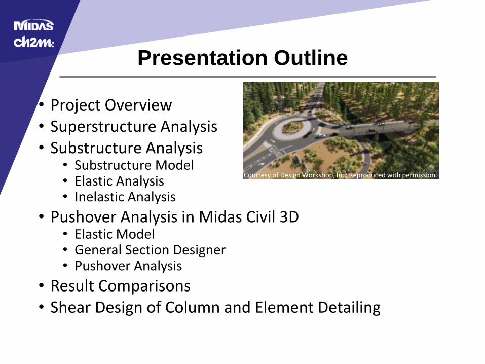
Presentation Outline
• Project Overview• Superstructure Analysis• Substructure Analysis
• Substructure Model• Elastic Analysis• Inelastic Analysis
• Pushover Analysis in Midas Civil 3D• Elastic Model • General Section Designer• Pushover Analysis
• Result Comparisons• Shear Design of Column and Element Detailing
Courtesy of Design Workshop, Inc; Reproduced with permission.
Presentation Overview
• Presentation Objectives• Develop understanding of:
• Modeling Techniques
• Inelastic Analysis
• Midas General Section Designer
• Midas Civil 3D Pushover Analysis
• Limitations of Presentation• Presentation will not:
• Discuss foundation bearing and sliding capacity
• Explain all theory behind topics
• Provide all steps required to use software
• Provide algorithms used for calculations

Project Overview
Project Overview
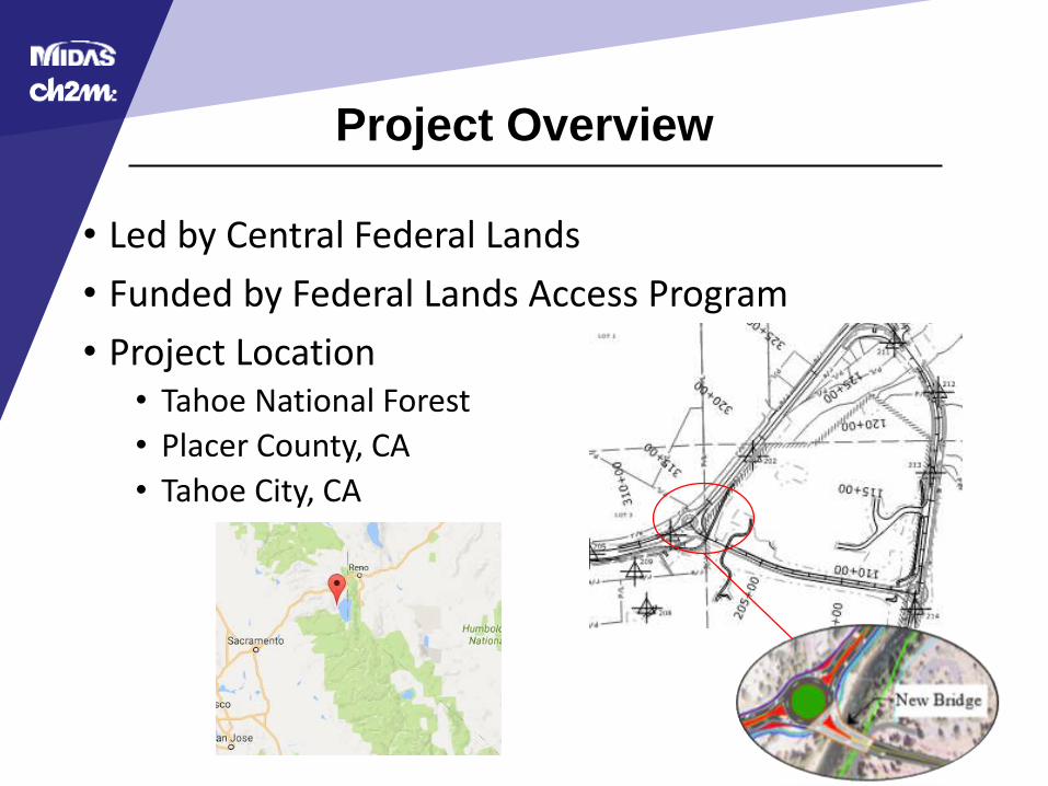
• Led by Central Federal Lands
• Funded by Federal Lands Access Program
• Project Location• Tahoe National Forest
• Placer County, CA
• Tahoe City, CA
Project Overview
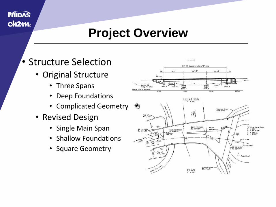
• Structure Selection• Original Structure
• Three Spans
• Deep Foundations
• Complicated Geometry
• Revised Design• Single Main Span
• Shallow Foundations
• Square Geometry
Project Overview
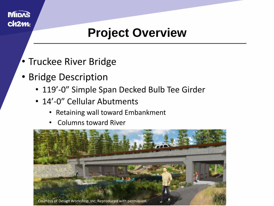
• Truckee River Bridge
• Bridge Description• 119’-0” Simple Span Decked Bulb Tee Girder
• 14’-0” Cellular Abutments• Retaining wall toward Embankment
• Columns toward River
Courtesy of Design Workshop, Inc; Reproduced with permission.
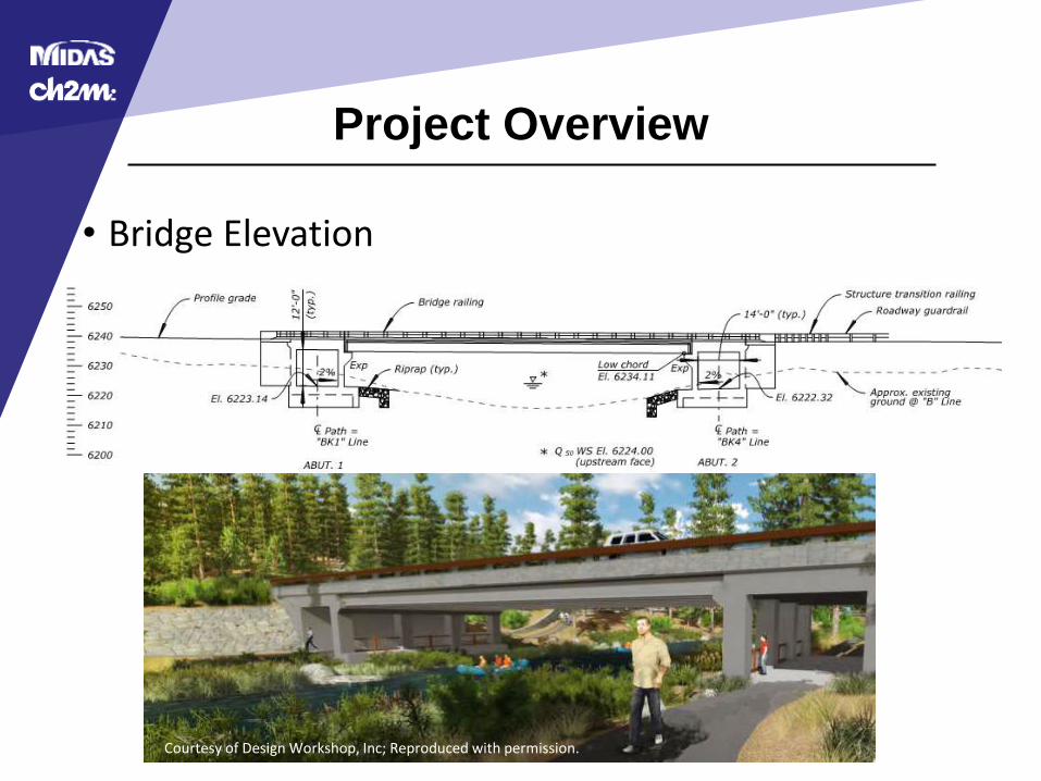
Project Overview
• Bridge Elevation
Courtesy of Design Workshop, Inc; Reproduced with permission.

Superstructure Analysis

Superstructure Analysis
• Superstructure• AASHTO LRFD 2012 6th Edition with Caltrans Amendments
• Decked Bulb Tee Girders – UDOT Typical Section
• Level Bearing Seats
• Steel Reinforced Elastomeric Bearing Pads
• CIP Concrete Topping
• CIP Diaphragms
• CIP Barriers
Typical Section
Superstructure Analysis
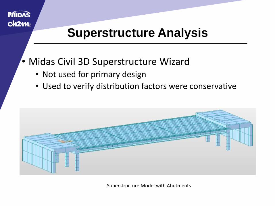
• Midas Civil 3D Superstructure Wizard• Not used for primary design
• Used to verify distribution factors were conservative
Superstructure Model with Abutments
Superstructure Analysis
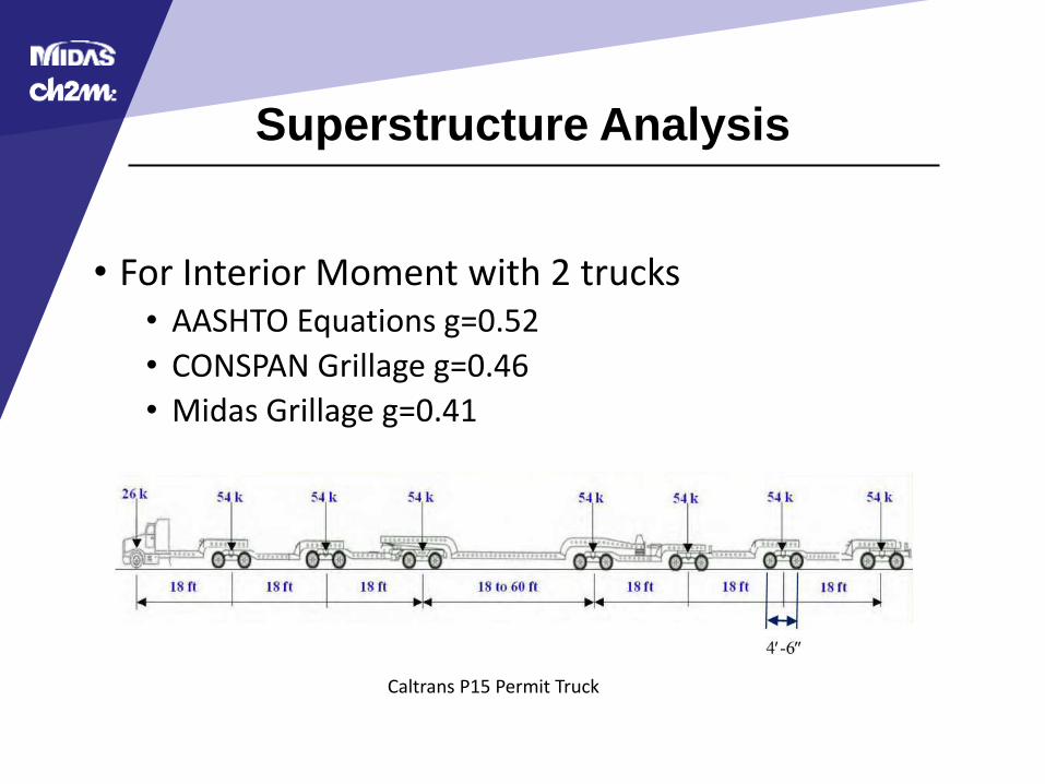
• For Interior Moment with 2 trucks• AASHTO Equations g=0.52
• CONSPAN Grillage g=0.46
• Midas Grillage g=0.41
Caltrans P15 Permit Truck
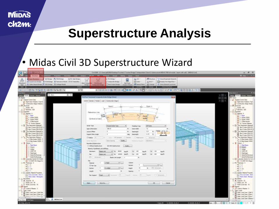
Superstructure Analysis
• Midas Civil 3D Superstructure Wizard

Substructure Analysis
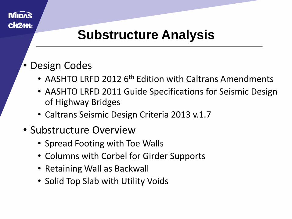
Substructure Analysis
• Design Codes• AASHTO LRFD 2012 6th Edition with Caltrans Amendments
• AASHTO LRFD 2011 Guide Specifications for Seismic Design of Highway Bridges
• Caltrans Seismic Design Criteria 2013 v.1.7
• Substructure Overview• Spread Footing with Toe Walls
• Columns with Corbel for Girder Supports
• Retaining Wall as Backwall
• Solid Top Slab with Utility Voids
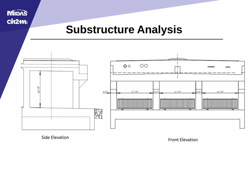
Substructure Analysis
Side Elevation Front Elevation

Substructure Analysis
• Substructure Model• Solid Element Model in CSiBridge
• Plate Element Model in Midas Civil 3D
• Beam Element Model was used for Corbel Design
Cellular Abutment Model Idealized Corbel Beam Model
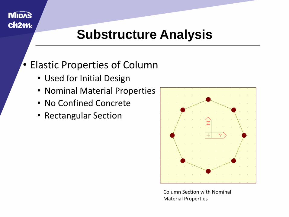
Substructure Analysis
• Elastic Properties of Column• Used for Initial Design
• Nominal Material Properties
• No Confined Concrete
• Rectangular Section
Column Section with Nominal Material Properties

Substructure Analysis
• Element Design• Bottom Slab, Back Wall, Top Slab
• Plate Analysis• Design Forces per 1 ft Strip• Reinforced Concrete Design
• Corbel Beam• Stiffness considerations• Designed as idealized beam• TxDOT Design Example based on AASHTO 2010 –
• AASHTO 5.13.2.4
• Columns• Designed to Remain elastic during Design Event
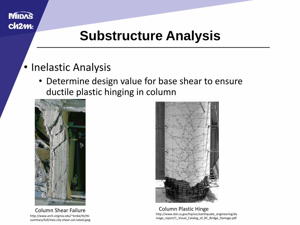
Substructure Analysis
• Inelastic Analysis• Determine design value for base shear to ensure
ductile plastic hinging in column
http://www.arch.virginia.edu/~km6e/tti/tti-summary/full/mex-city-shear-col-noted.jpeg
http://www.dot.ca.gov/hq/esc/earthquake_engineering/damage_report/1_Visual_Catalog_of_RC_Bridge_Damage.pdf
Column Shear Failure Column Plastic Hinge
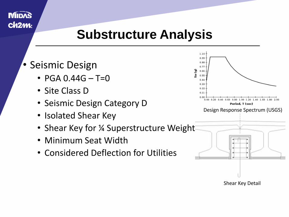
Substructure Analysis
• Seismic Design• PGA 0.44G – T=0
• Site Class D
• Seismic Design Category D
• Isolated Shear Key
• Shear Key for ¼ Superstructure Weight
• Minimum Seat Width
• Considered Deflection for Utilities
Design Response Spectrum (USGS)
Shear Key Detail
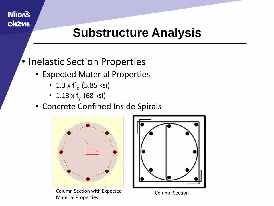
Substructure Analysis
• Inelastic Section Properties• Expected Material Properties
• 1.3 x f`c (5.85 ksi)
• 1.13 x fy (68 ksi)
• Concrete Confined Inside Spirals
Column Section with Expected Material Properties
Column Section
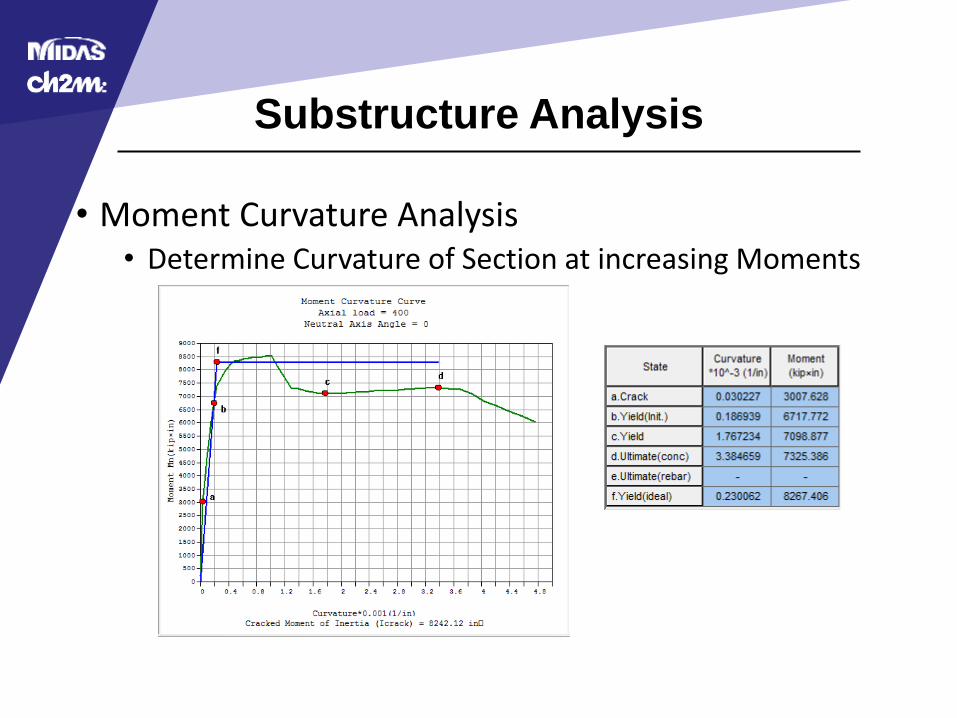
Substructure Analysis
• Moment Curvature Analysis• Determine Curvature of Section at increasing Moments

Substructure Analysis
• Pushover Analysis• Moment Curvature Analysis
• Determine Overstrength Moments• Mpo=1.2 x Mp Caltrans SDC - Section 4.3
• Calculate Shear with only Service Axial Force (Dead Load)• Vo=(Mpo-top+Mpo-bot)/h
• Sum Base Shears
• Apply Total Shear as Lateral Force
• Recalculate Axial Forces Include Overturning
• Iterate until Lateral Force and Total Shear Converge
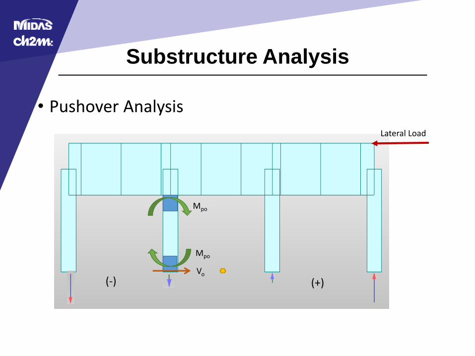
Substructure Analysis
• Pushover Analysis
(-) (+)
Mpo
Mpo
Vo
Lateral Load
Substructure Analysis
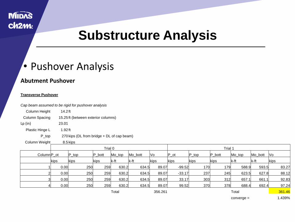
• Pushover AnalysisAbutment Pushover
Transverse Pushover
Cap beam assumed to be rigid for pushover analysis
Column Height 14.2 ft
Column Spacing 15.25 ft (between exterior columns)
Lp (in) 23.01
Plastic Hinge L 1.92 ft
P_top 270 kips (DL from bridge + DL of cap beam)
Column Weight 8.5 kips
Trial 0 Trial 1
Column P_ot P_top P_bott Mo_top Mo_bott Vo P_ot P_top P_bott Mo_top Mo_bott Vo
kips kips kips k-ft k-ft kips kips kips kips k-ft k-ft kips
1 0.00 250 259 630.2 634.5 89.07 -99.52 170 179 588.9 593.5 83.27
2 0.00 250 259 630.2 634.5 89.07 -33.17 237 245 623.5 627.8 88.12
3 0.00 250 259 630.2 634.5 89.07 33.17 303 312 657.1 661.1 92.83
4 0.00 250 259 630.2 634.5 89.07 99.52 370 378 688.4 692.4 97.24
Total 356.261 Total 361.46
converge = 1.439%
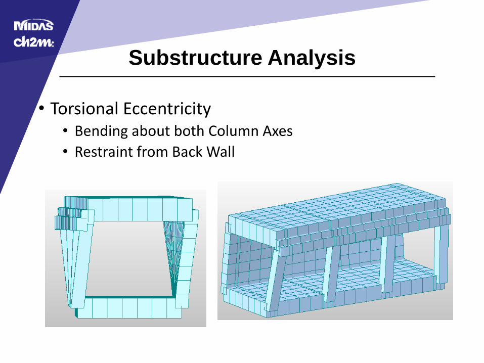
Substructure Analysis
• Torsional Eccentricity• Bending about both Column Axes
• Restraint from Back Wall
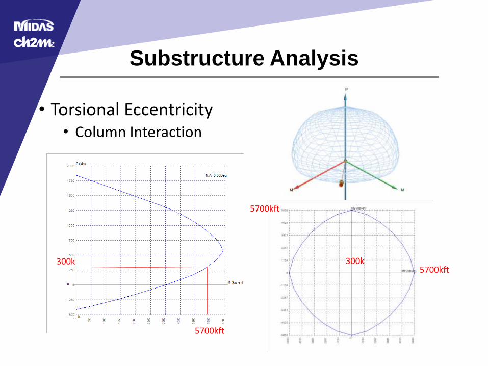
Substructure Analysis
• Torsional Eccentricity• Column Interaction
300k
5700kft
5700kft
5700kft300k
Pushover Analysis in Midas Civil 3D
Pushover Analysis in Midas Civil 3D
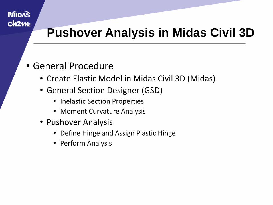
• General Procedure• Create Elastic Model in Midas Civil 3D (Midas)
• General Section Designer (GSD)• Inelastic Section Properties
• Moment Curvature Analysis
• Pushover Analysis• Define Hinge and Assign Plastic Hinge
• Perform Analysis
Pushover Analysis in Midas Civil 3D
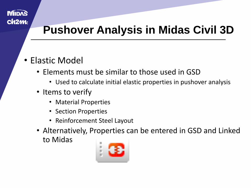
• Elastic Model• Elements must be similar to those used in GSD
• Used to calculate initial elastic properties in pushover analysis
• Items to verify• Material Properties
• Section Properties
• Reinforcement Steel Layout
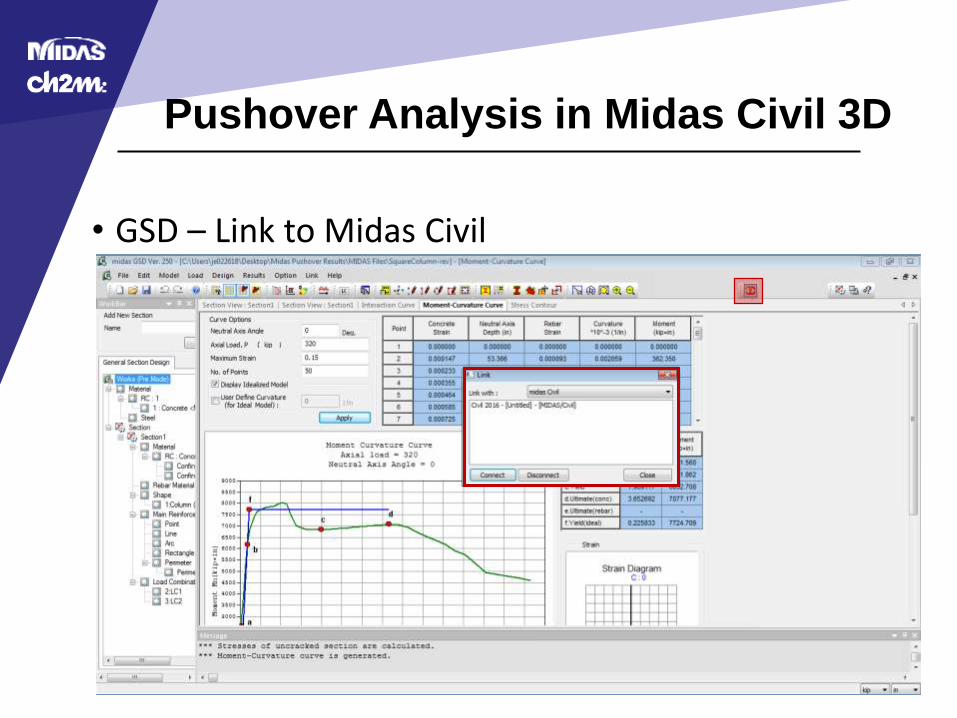
• Alternatively, Properties can be entered in GSD and Linked to Midas
Pushover Analysis in Midas Civil 3D
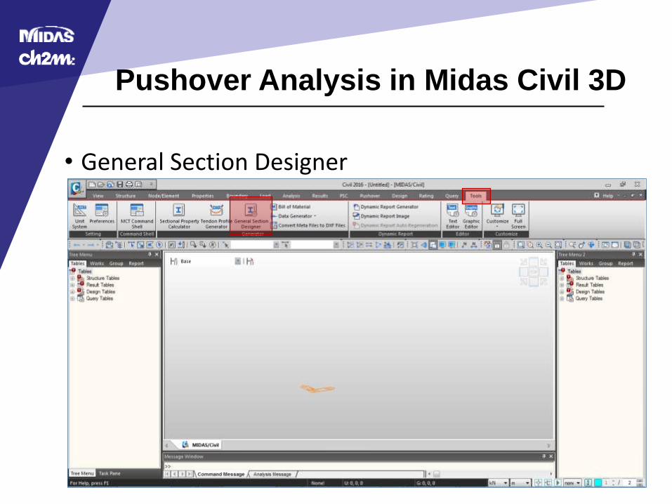
• General Section Designer
Pushover Analysis in Midas Civil 3D
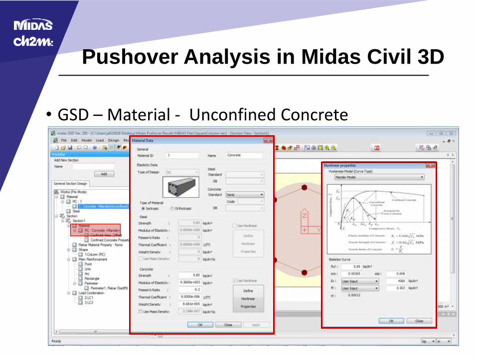
• GSD – Material - Unconfined Concrete

Pushover Analysis in Midas Civil 3D
• GSD – Confined Area
Pushover Analysis in Midas Civil 3D
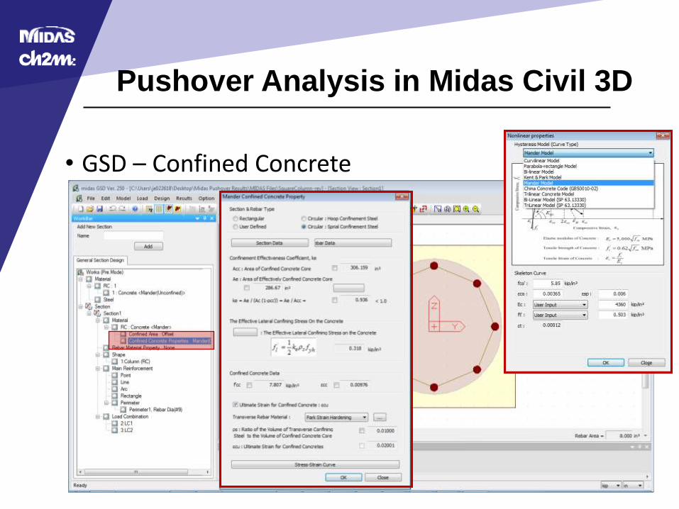
• GSD – Confined Concrete
Pushover Analysis in Midas Civil 3D
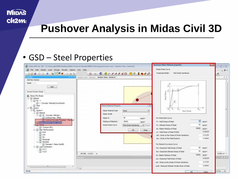
• GSD – Steel Properties
Pushover Analysis in Midas Civil 3D
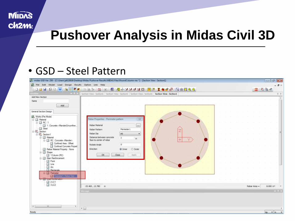
• GSD – Steel Pattern
Pushover Analysis in Midas Civil 3D
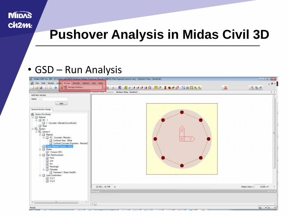
• GSD – Run Analysis
Pushover Analysis in Midas Civil 3D
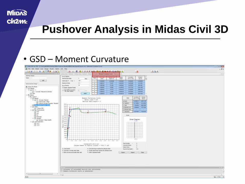
• GSD – Moment Curvature
Pushover Analysis in Midas Civil 3D
• GSD – Link to Midas Civil
Pushover Analysis in Midas Civil 3D
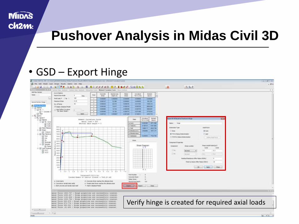
• GSD – Export Hinge
Verify hinge is created for required axial loads
Pushover Analysis in Midas Civil 3D
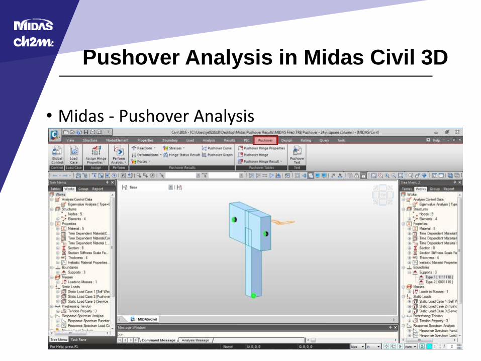
• Midas - Pushover Analysis
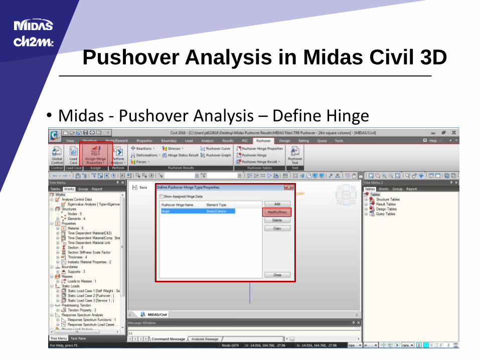
Pushover Analysis in Midas Civil 3D
• Midas - Pushover Analysis – Define Hinge
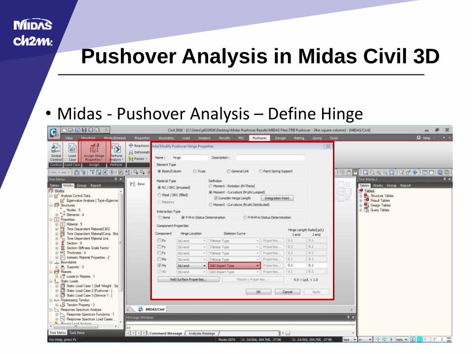
Pushover Analysis in Midas Civil 3D
• Midas - Pushover Analysis – Define Hinge
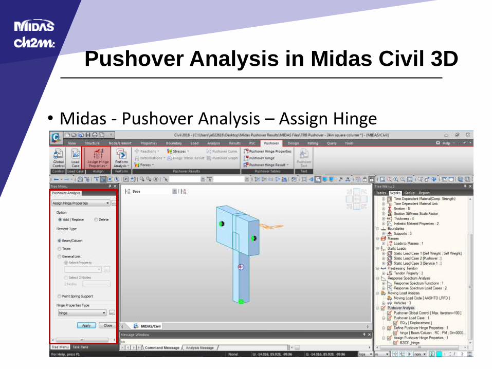
Pushover Analysis in Midas Civil 3D
• Midas - Pushover Analysis – Assign Hinge

Pushover Analysis in Midas Civil 3D
• Midas - Pushover Analysis – Load Case
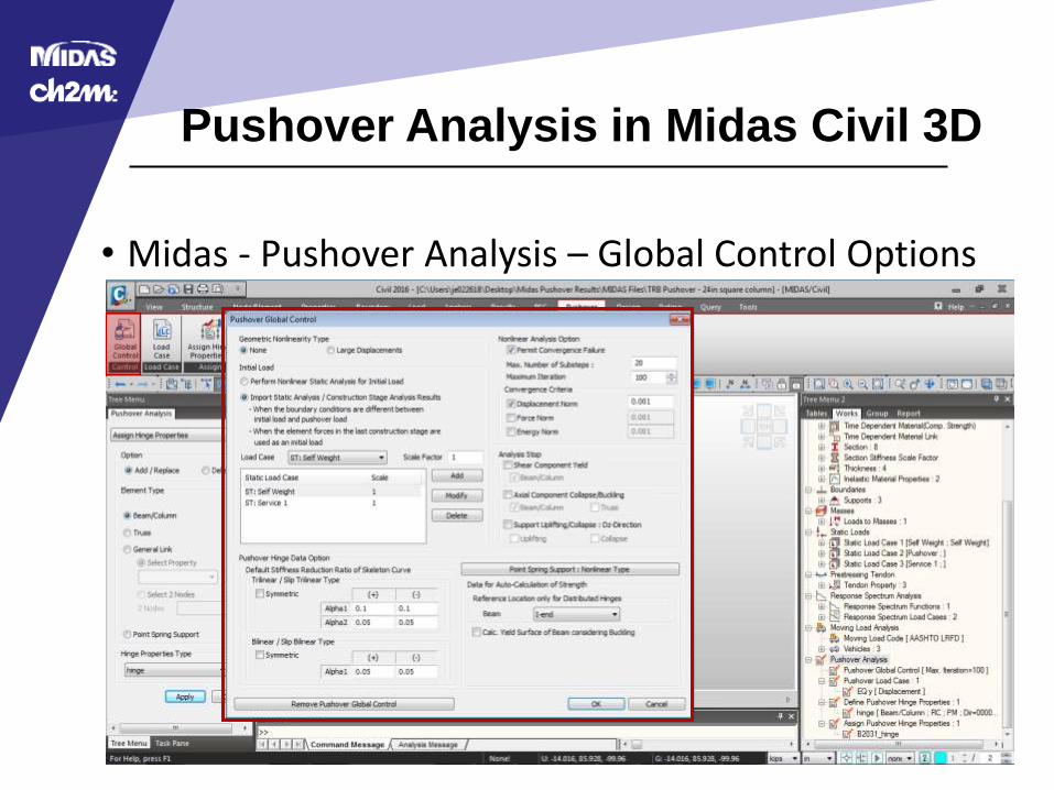
Pushover Analysis in Midas Civil 3D
• Midas - Pushover Analysis – Global Control Options
Pushover Analysis in Midas Civil 3D
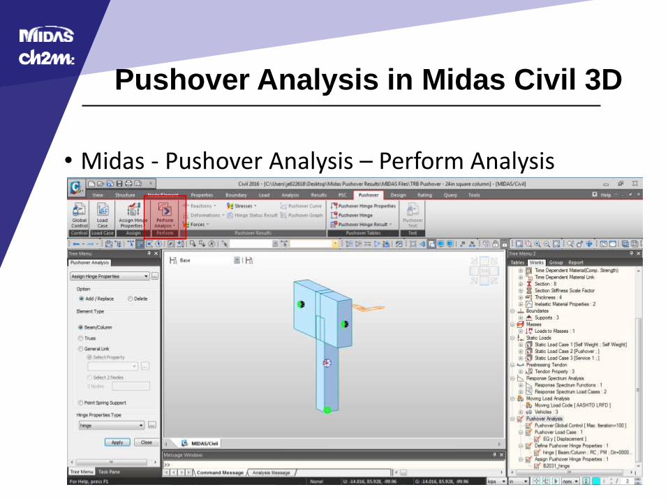
• Midas - Pushover Analysis – Perform Analysis
Pushover Analysis in Midas Civil 3D
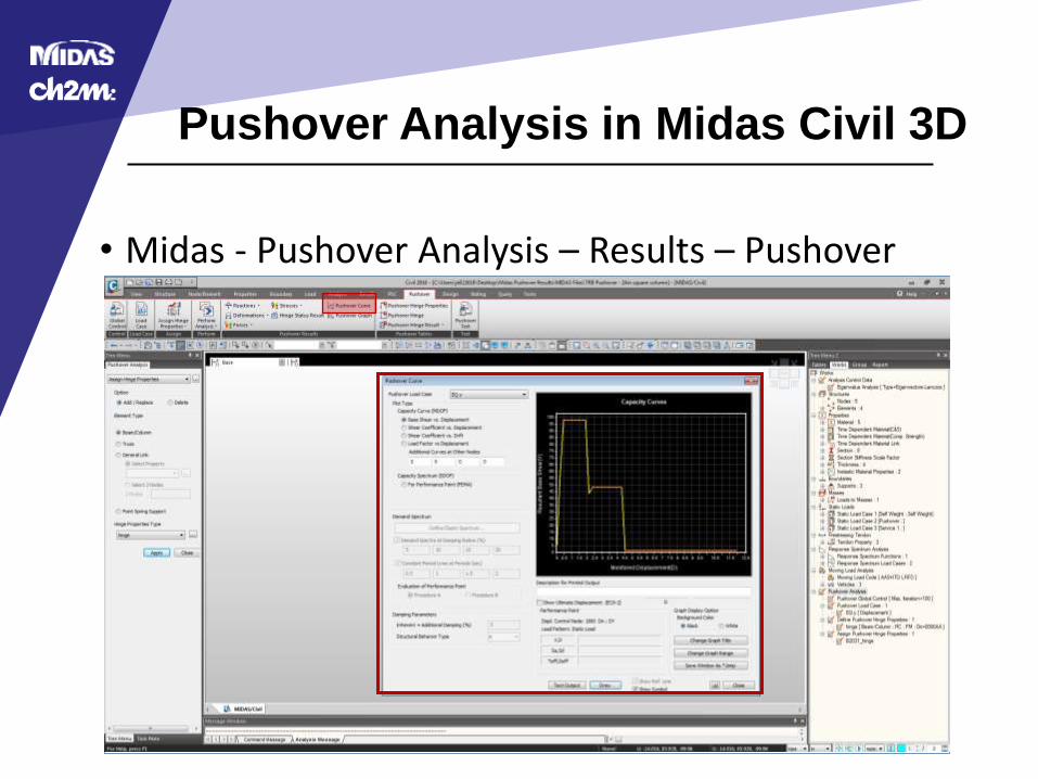
• Midas - Pushover Analysis – Results – Pushover Curve
Pushover Analysis in Midas Civil 3D
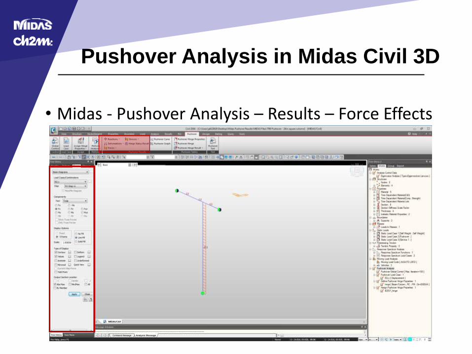
• Midas - Pushover Analysis – Results – Force Effects
Pushover Analysis in Midas Civil 3D
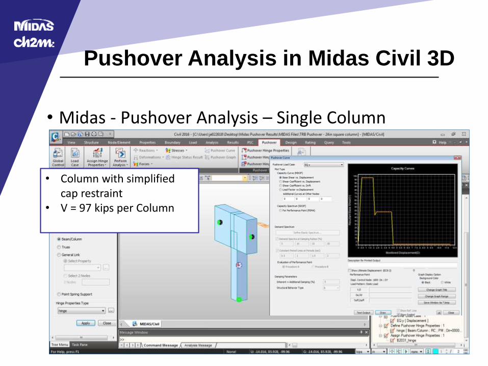
• Midas - Pushover Analysis – Single Column
• Column with simplified cap restraint
• V = 97 kips per Column
Pushover Analysis in Midas Civil 3D
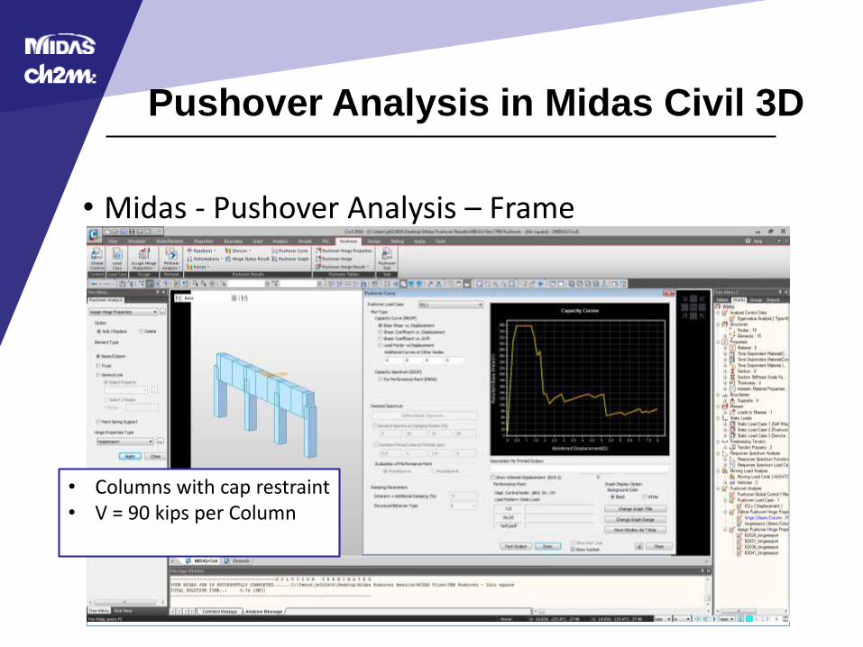
• Midas - Pushover Analysis – Frame
• Columns with cap restraint• V = 90 kips per Column
Pushover Analysis in Midas Civil 3D
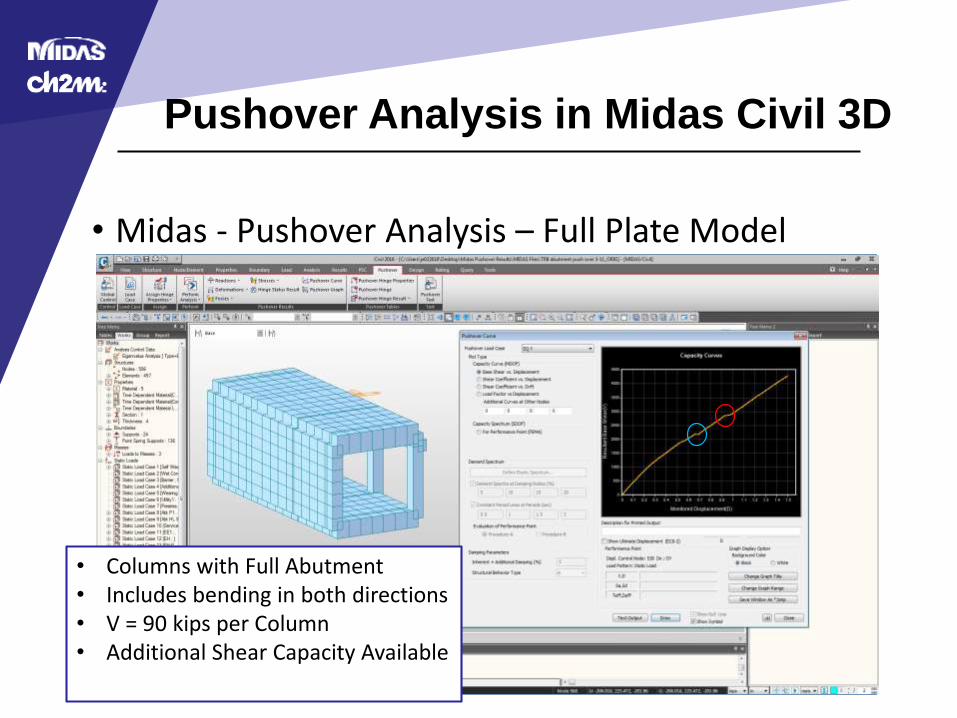
• Midas - Pushover Analysis – Full Plate Model
• Columns with Full Abutment• Includes bending in both directions• V = 90 kips per Column• Additional Shear Capacity Available
Pushover Analysis in Midas Civil 3D
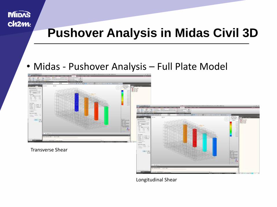
• Midas - Pushover Analysis – Full Plate Model
Transverse Shear
Longitudinal Shear
Pushover Analysis in Midas Civil 3D
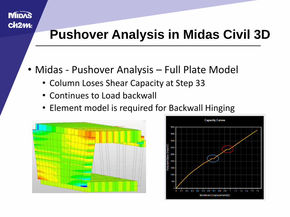
• Midas - Pushover Analysis – Full Plate Model• Column Loses Shear Capacity at Step 33
• Continues to Load backwall
• Element model is required for Backwall Hinging

Result Comparison
Result Comparison
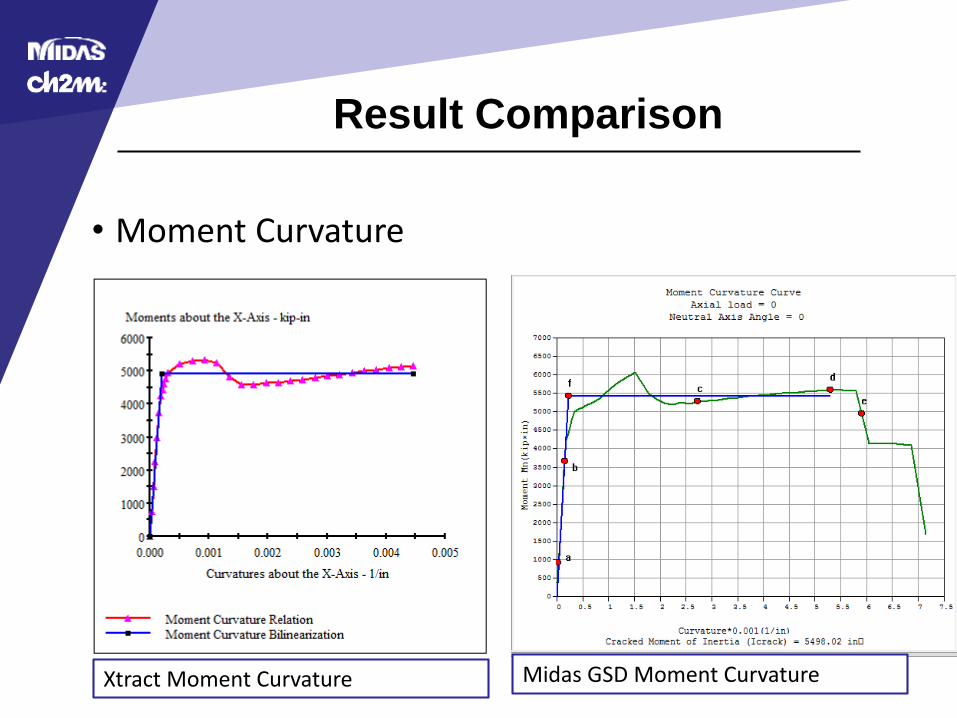
• Moment Curvature
Xtract Moment Curvature Midas GSD Moment Curvature
Result Comparison
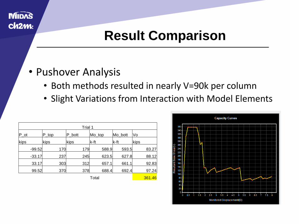
• Pushover Analysis• Both methods resulted in nearly V=90k per column
• Slight Variations from Interaction with Model Elements
Trial 1
P_ot P_top P_bott Mo_top Mo_bott Vo
kips kips kips k-ft k-ft kips
-99.52 170 179 588.9 593.5 83.27
-33.17 237 245 623.5 627.8 88.12
33.17 303 312 657.1 661.1 92.83
99.52 370 378 688.4 692.4 97.24
Total 361.46
Result Comparison
• Reasons for differences• Steel Model
• Xtract – Bilinear with Strain Hardening
• GSD – Kent and Park with Strain Hardening
• Results vary by 25% without strain hardening
• Variations in calculations
Shear Design and Element Detailing
Shear Design
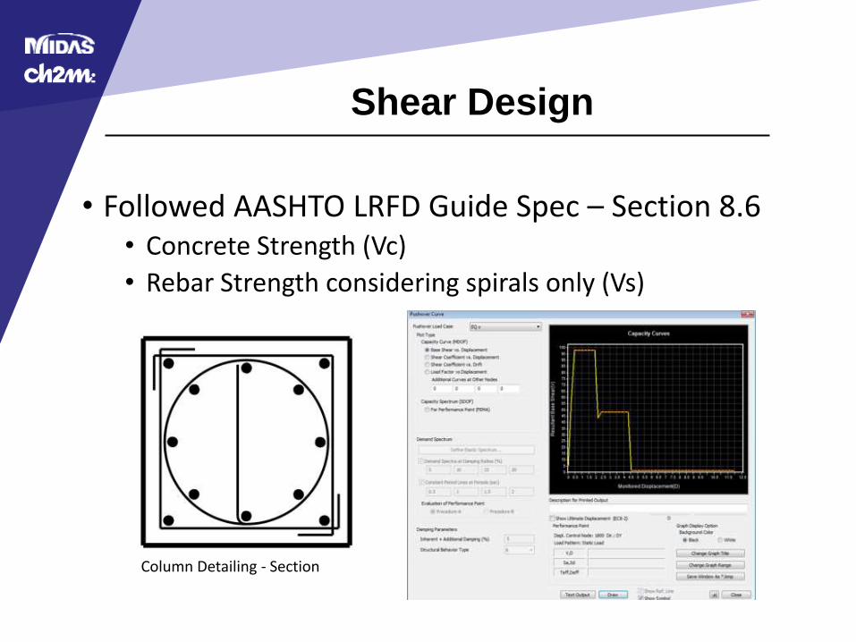
• Followed AASHTO LRFD Guide Spec – Section 8.6• Concrete Strength (Vc)
• Rebar Strength considering spirals only (Vs)
Column Detailing - Section
Element Detailing
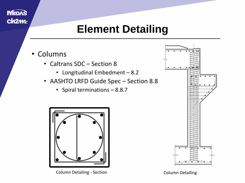
• Columns• Caltrans SDC – Section 8
• Longitudinal Embedment – 8.2
• AASHTO LRFD Guide Spec – Section 8.8• Spiral terminations – 8.8.7
Column DetailingColumn Detailing - Section
Element Detailing
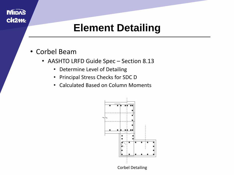
• Corbel Beam• AASHTO LRFD Guide Spec – Section 8.13
• Determine Level of Detailing
• Principal Stress Checks for SDC D
• Calculated Based on Column Moments
Corbel Detailing
Element Detailing
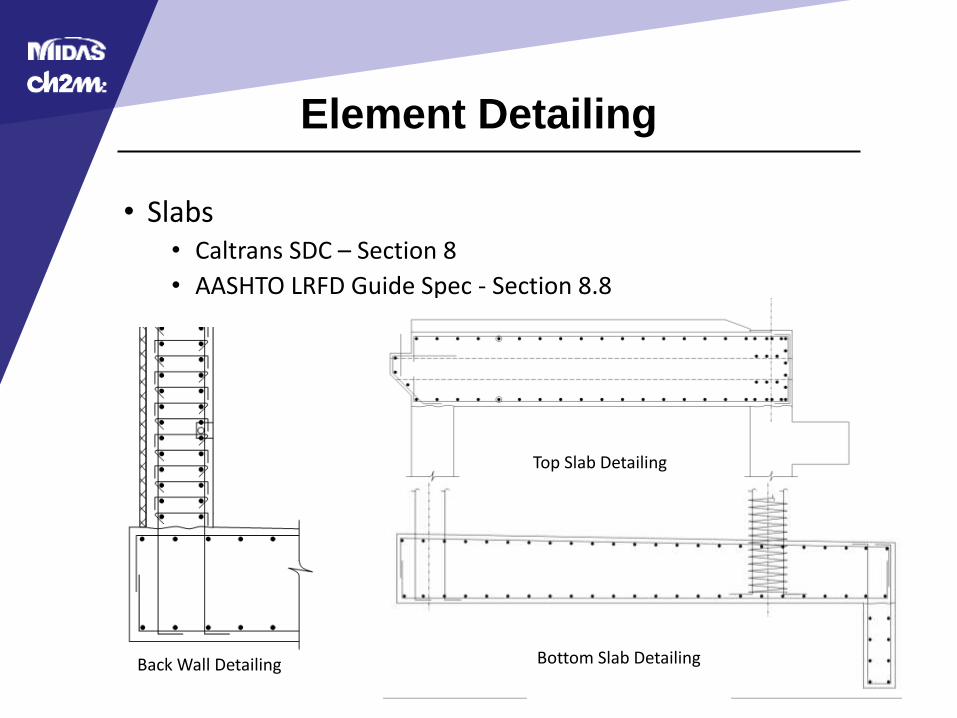
• Slabs• Caltrans SDC – Section 8
• AASHTO LRFD Guide Spec - Section 8.8
Top Slab Detailing
Bottom Slab DetailingBack Wall Detailing
Summary
• Elastic Analysis
• Inelastic Analysis
• Midas Civil 3D Pushover Analysis
• Result Checking
• Shear Design
Acknowledgements
• Midasoft
• Central Federal Lands
• CH2M
• Design Workshop
• LEAP – CONSPAN
• CSiBridge
• TxDOT
• XTRACT
References
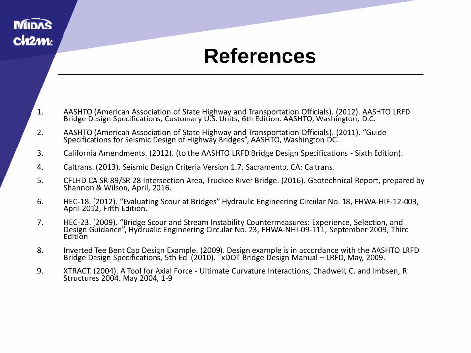
1. AASHTO (American Association of State Highway and Transportation Officials). (2012). AASHTO LRFD Bridge Design Specifications, Customary U.S. Units, 6th Edition. AASHTO, Washington, D.C.
2. AASHTO (American Association of State Highway and Transportation Officials). (2011). “Guide Specifications for Seismic Design of Highway Bridges”, AASHTO, Washington DC.
3. California Amendments. (2012). (to the AASHTO LRFD Bridge Design Specifications - Sixth Edition).
4. Caltrans. (2013). Seismic Design Criteria Version 1.7. Sacramento, CA: Caltrans.
5. CFLHD CA SR 89/SR 28 Intersection Area, Truckee River Bridge. (2016). Geotechnical Report, prepared by Shannon & Wilson, April, 2016.
6. HEC-18. (2012). “Evaluating Scour at Bridges” Hydraulic Engineering Circular No. 18, FHWA-HIF-12-003, April 2012, Fifth Edition.
7. HEC-23. (2009). “Bridge Scour and Stream Instability Countermeasures: Experience, Selection, and Design Guidance”, Hydrualic Engineering Circular No. 23, FHWA-NHI-09-111, September 2009, Third Edition
8. Inverted Tee Bent Cap Design Example. (2009). Design example is in accordance with the AASHTO LRFD Bridge Design Specifications, 5th Ed. (2010). TxDOT Bridge Design Manual – LRFD, May, 2009.
9. XTRACT. (2004). A Tool for Axial Force - Ultimate Curvature Interactions, Chadwell, C. and Imbsen, R. Structures 2004. May 2004, 1-9
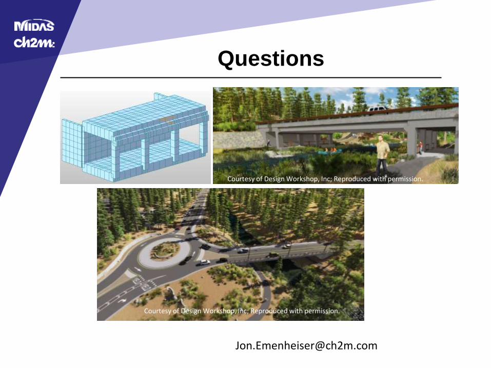
Questions
Courtesy of Design Workshop, Inc; Reproduced with permission.
Courtesy of Design Workshop, Inc; Reproduced with permission.