
PureBond® Welding Tool - Entegris following procedures. Entegris recommends that no person weld...
26
ADVANCED MATERIALS HANDLING | MANUAL PureBond ® Welding Tool Operations manual
Transcript of PureBond® Welding Tool - Entegris following procedures. Entegris recommends that no person weld...

ADVANCED MATERIALS HANDLING | MANUAL
PureBond® Welding ToolOperations manual


1
PUREBOND WELDING TOOL
Operations Manual | P/N 230-21 Rev E | Entegris, Inc.
TABLE OF CONTENTS—Introduction ................................................................... 2
Facilities and Environment ........................................... 3
Welding Tools Ordering Information ......................... 3
Equipment Setup .......................................................... 4
25.4 mm (1") and 50.8 mm (2") Benchtop Welding Tools ........................................... 4
25.4 mm (1") PureBond Welding Tool with Standard Clamps ........................................................ 4
25.4 mm (1") PureBond Welding Tool with Thin Clamps ................................................................. 6
50.8 mm (2") PureBond Welding Tool ................... 6
Welding Steps ................................................................ 8
Standard and Minimum Welds ................................ 8
Gauging Using Standard Clamps ............................ 8
Gauging Using Thin Clamps .................................... 8
Facing ............................................................................ 9
Welding Closure Distance ......................................... 9
Welding ....................................................................... 10
Supporting Pipe Lengths ......................................... 11
Capping Fittings/Pipe ............................................... 11
Protecting Valves ....................................................... 11
Weld Inspection and Qualification .......................... 12
Weld Visual Inspection ............................................ 12
Weld Flex Inspection ............................................... 12
Dimensional Welding .................................................. 13
Weld Types ................................................................. 13
Component Dimensions ........................................ 14
Weld Sequencing ...................................................... 14
Welding Tips .............................................................. 14
Helpful Hints .............................................................. 14
Welded System Requirements .................................. 15
Installed Pipe Support ............................................. 15
Thermal Expansion and Contraction – Formula 1 ................................................................... 16
Thermal Expansion and Contraction – Formula 2 ................................................................... 16
Modifying a Welded System ...................................... 17
Rewelding Before Commissioning ....................... 17
Rewelding After Commissioning .......................... 17
Safety Considerations During Welding and After Installation .................................................. 17
Material Information ................................................ 17
Warning ...................................................................... 18
Heating Element Safety ........................................... 18
Weld Cooling ............................................................. 18
Electrical Shock ........................................................ 18
Installed System Safety ............................................ 18
Technical Information ................................................ 19
Creep Resistance ...................................................... 19
Long-term Pipe Strength ........................................ 19
Safety Factor for Pipe .............................................. 20
Weld Strength ............................................................ 20
Short-term Burst ......................................................... 21
Cyclic Shock Test ........................................................ 21
Tensile Test ................................................................... 21
Definitions .................................................................... 22
For More Information ................................................ 24
Terms and Conditions of Sale .................................. 24
Limited Warranty ........................................................ 24
2
PUREBOND WELDING TOOL
Operations Manual | P/N 230-21 Rev E | Entegris, Inc.
INTRODUCTION—PureBond® pipe components were the first weld-
able pipe products of PFA. Entegris developed these
products in response to industry requests for a pipe
system that is totally leak proof and has all of the
chemical inertness of PFA. We used our expertise
with PFA and fluid handling to design and produce
PureBond pipe products using a total system ap-
proach. Entegris developed a complete line of
system components including Schedule 40 pipe,
Schedule 80 pipe, fittings, valves, and accessories.
During the development of PureBond pipe products,
design considerations included versatility and ease
of installation. As a result, PureBond pipe welding
equipment is portable, lightweight, and easy to use.
PureBond pipe components are manufactured
from PFA so they are chemically resistant and inert.
PureBond pipe will not deteriorate or leach; thus,
they will not contaminate your process chemicals
or pure water.
PATENTED PROCESS
Entegris has designed a unique PureBond pipe
welding process. Because PFA does not adapt well
to conventional welding techniques, a PureBond
pipe weld is made with a patented noncontact
welding method (U.S. patent no. 4,929,293). The
PureBond pipe welding tool heats the ends of the
pipe, fitting, or valve to be joined to a molten state,
and presses them together.
Our PureBond pipe welding process eliminates
installation variables. The PureBond pipe welding tool
holds pipe, fittings, and valves in alignment. A facing
tool presets the distance the parts extend into the
welding tool, and welding tool guides ensure the
heater is centered. Preset locking prevents molten
ends from being pressed too far together. The result
of the PureBond pipe welding process is bonds of
consistent quality.
The PureBond pipe weld eliminates threads so there
is no danger of cold flow and its resultant leakage.
These welds are as strong as the pipe, giving you a
safer system than you get with a threaded system.
Entegris has technical personnel available to consult
regarding PureBond pipe custom component and
assembly design.
NOTE: PureBond weldable pipe products are specifical- ly designed, tested, and characterized from a material stand point to work with PureBond fitting and pipe components manufactured by Entegris. Customer assumes the risk of proper fit and weld connection integrity if PureBond weldable pipe products are con-nected to components manufactured by third parties. Further, customer will assume the risk of proper fit and weld connection integrity if PureBond weldable pipe products are joined using tools that are not either manufactured by or endorsed in writing by Entegris.
BUTT WELDING METHOD
The butt welding method used on PureBond pipe
products is an uncomplicated, visual procedure with
straightforward instructions. No timing cycles are
necessary. The visual procedure allows the operator
to concentrate on the work rather than a clock.
Visually, the operator can tell when the ends have
melted to the required degree for welding.
The principle behind the butt welding method is
to heat two surfaces using a noncontact heater to
a welding temperature, make contact between the
two surfaces, and allow the two surfaces to fuse by
application of pressure. The pressure causes flow
of the melted materials, which affects mixing and
thus welding. Upon cooling, the original interfaces
are gone and the two parts are united. Nothing is
added to or changed chemically between the two
joined pieces.
For consistently strong welds, you must adhere to
the following procedures. Entegris recommends
that no person weld PureBond pipe products for
service unless that person fully understands the
welding procedures.

PUREBOND WELDING TOOL
3Operations Manual | P/N 230-21 Rev E | Entegris, Inc.
FACILITIES AND ENVIRONMENT—Use the tool in a clean, dry area that is protected from
drafty conditions. Normal workplace ventilation is
usually acceptable. Drafts may cause uneven heating
of the pipe ends resulting in poor weld quality. (See
Guide to the Safe Handling of Fluoropolymer Resins,
Society of the Plastics Industry, Inc.)
To reduce weld contamination and create an opera-
tor-safe environment, use the tool on a flat, clean
bench or cart. Always use specified voltage to con-
nect heater (see table below). If possible, connect to
a voltage that is within ±5% of rating.
Replacement parts available from the factory upon request.*To lease a PureBond welding tool, add an “R" to the end of the part number.† Heater is CE marked per Low Voltage Directive 73 /23/EEC (EN60335-1 and EN60335-2-45).
NOTE: Power supply cord on heater cannot be replaced. If cord is damaged, the appliance should be scrapped.
WELDING TOOLS ORDERING INFORMATION—25.4 mm (1") benchmount kit
Part number* Voltage Cycles Power
213-67 120 VAC 50 /60 Hz 1280 Watts
213-68 100 VAC 50 /60 Hz 1280 Watts
213-69 † 230 VAC 50 /60 Hz 1280 Watts
Replacement parts
Part number* Description
213-47 25.4 mm (1") facing tool
1223-014 Right replacement blade
1223-015 Left replacement blade
213-33 12.7 mm (1⁄2") gauging tool
213-34 19.05 mm (3⁄4") gauging tool
213-35 25.4 mm (1") gauging tool
213-42 Pipe shear with spacer plate
213-31 Heater holder
213-48 Thin clamp assembly
1220-003 12.7 mm (1⁄2") inserts – standard
1220-004 19.05 mm (3⁄4") inserts – standard
213-28 25.4 mm (1") kit with all parts
1220-079 12.7 mm (1⁄2") inserts – thin
1220-078 19.05 mm (3⁄4") inserts – thin
213-44 120 VAC heater
213-45 100 VAC heater
213-46 † 230 VAC heater
1220-179 6.35 mm (1⁄4") inserts – thin
213-84 6.35 mm (1⁄4") kit with all parts
1223-027 Replacement chain for 25.4 mm (1") facing tool
215-164 shears Replacement spring for standard pipe
213-212 Heat shield
50.8 mm (2") benchmount kit
Part number* Voltage Cycles Power
213-70 120 VAC 50 /60 Hz 1280 Watts
213-71 100 VAC 50 /60 Hz 1280 Watts
213-72 † 230 VAC 50 /60 Hz 1280 Watts
Replacement parts
Part number* Description
213-51 50.8 mm (2") facing tool
1223-018 Replacement blades (need 2)
213-33 12.7 mm (1⁄2") gauging tool
213-34 19.05 mm (3⁄4") gauging tool
213-35 25.4 mm (1") gauging tool
213-52 50.8 mm (2") gauging tool
213-30 Pipe shear – standard
1223-021 Replacement blades (set)
213-53 Pipe shear – 50.8 mm (2") pipe
213-31 Heater holder
1220-205 12.7 mm (1⁄2") inserts
1220-206 19.05 mm (3⁄4") inserts
1220-207 25.4 mm (1") inserts
213-55 120 VAC heater
213-56 100 VAC heater
213-57 † 230 VAC heater
1223-028 Replacement chain for 50.8 mm (2") facing tool
215-164 shears Replacement spring for standard pipe
213-212 Heat shield
4
PUREBOND WELDING TOOL
Operations Manual | P/N 230-21 Rev E | Entegris, Inc.
EQUIPMENT SETUP—
25.4 MM (1") AND 50.8 MM (2") BENCHTOP WELDING TOOLS
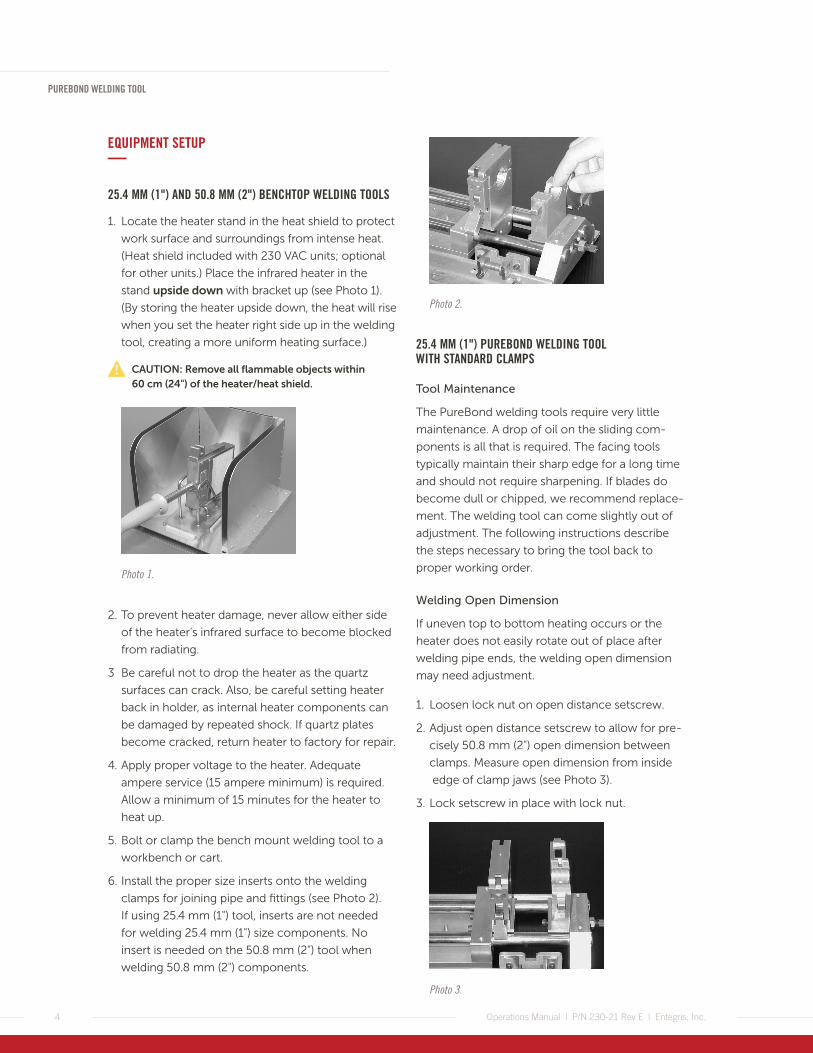
1. Locate the heater stand in the heat shield to protect
work surface and surroundings from intense heat.
(Heat shield included with 230 VAC units; optional
for other units.) Place the infrared heater in the
stand upside down with bracket up (see Photo 1).
(By storing the heater upside down, the heat will rise
when you set the heater right side up in the welding
tool, creating a more uniform heating surface.)
CAUTION: Remove all flammable objects within 60 cm (24") of the heater/heat shield.
Photo 1.
2. To prevent heater damage, never allow either side
of the heater’s infrared surface to become blocked
from radiating.
3 Be careful not to drop the heater as the quartz
surfaces can crack. Also, be careful setting heater
back in holder, as internal heater components can
be damaged by repeated shock. If quartz plates
become cracked, return heater to factory for repair.
4. Apply proper voltage to the heater. Adequate
ampere service (15 ampere minimum) is required.
Allow a minimum of 15 minutes for the heater to
heat up.
5. Bolt or clamp the bench mount welding tool to a
workbench or cart.
6. Install the proper size inserts onto the welding
clamps for joining pipe and fittings (see Photo 2).
If using 25.4 mm (1") tool, inserts are not needed
for welding 25.4 mm (1") size components. No
insert is needed on the 50.8 mm (2") tool when
welding 50.8 mm (2") components.
Photo 2.
25.4 MM (1") PUREBOND WELDING TOOL WITH STANDARD CLAMPS
Tool Maintenance
The PureBond welding tools require very little
maintenance. A drop of oil on the sliding com-
ponents is all that is required. The facing tools
typically maintain their sharp edge for a long time
and should not require sharpening. If blades do
become dull or chipped, we recommend replace-
ment. The welding tool can come slightly out of
adjustment. The following instructions describe
the steps necessary to bring the tool back to
proper working order.
Welding Open Dimension
If uneven top to bottom heating occurs or the
heater does not easily rotate out of place after
welding pipe ends, the welding open dimension
may need adjustment.
1. Loosen lock nut on open distance setscrew.
2. Adjust open distance setscrew to allow for pre-
cisely 50.8 mm (2") open dimension between
clamps. Measure open dimension from inside
edge of clamp jaws (see Photo 3).
3. Lock setscrew in place with lock nut.
Photo 3.

PUREBOND WELDING TOOL
5Operations Manual | P/N 230-21 Rev E | Entegris, Inc.
Heater Bracket Adjustment
If the two sides of the pipe weld do not heat up
evenly, an unacceptable, uneven weld will result.
The heater bracket may need adjustment.
1. Install pipe into welding tool, gauge and face off.
2. Rotate nonenergized cold heater into position
and observe alignment.
3. If the heater does not sit perpendicular to the
pipe ends, gently apply pressure to the heater
in the direction required. This will gradually form
the sheet metal housing the bracket is connected
to and will correct misalignment (see Photo 4).
Photo 4.
4. Should the heater not be equidistant between the
pipe ends, loosen the cap screws holding the angle
brackets to the welding tool. Adjust in the direction
required and retighten (see Photo 5).
Photo 5.
5. Should the heater still not be equidistant or come
in contact with the pipe when it is swung into
place, loosen the cap screws holding the bracket
to the heater (see Photo 6).
6. Adjust the heater in the direction required and
retighten the bracket locking it in place.
Photo 6.
Pipe/Fitting Alignment
If the ends are not aligned properly while clamped
in the welding tool, an unacceptable offset weld will
result. The clamps holding the pipe may need
alignment.
1. Loosen the two cap screws that hold the clamp
opposite the sliding base plate assembly.
2. Push welding tool handle to the closed position
and securely clamp a section of pipe approximately
152.4 mm (6") in length between both clamps (see
Photo 7).
3. Retighten the two cap screws to lock the clamp
in position. This will ensure proper component
alignment during welding.
Photo 7.
Cap screws

6
PUREBOND WELDING TOOL
Operations Manual | P/N 230-21 Rev E | Entegris, Inc.
25.4 MM (1") PUREBOND WELDING TOOL WITH THIN CLAMPS
Installation and Adjustment
1. Remove the standard width clamps from the bench
mount welding tool.
2. Assemble the proper thin clamp to sliding base
plate assembly and tighten cap screws securely
(see Photo 8). Position clamp so as not to cause
any binding in sliding base operation.
NOTE: The two thin clamps are not interchangeable from side to side, and care should be taken to assemble so clamp latches face toward front of tool.
Photo 8.
Clamp latches
Front
3. Assemble the other clamp to the bench mount tool
but do not tighten cap screws.
4. When joining pipe and fittings less than 25.4 mm
(1") in size, install pipe inserts in clamps.
5. Push handle to closed position and secure a
section of pipe approximately 152.4 mm (6") in
length between both clamps. Clamping tension
can be adjusted by rotating the thumb wheel on
top of the clamp. (Be sure to unclamp pipe prior
to adjusting.)
6. Securely tighten two remaining cap screws on
clamp opposite the sliding base plate assembly.
This will ensure proper component alignment
during welding.
7. Remove pipe from clamps and allow sliding base
plate assembly to return to open position. The
bench mount tool is now ready for shortened
welding distance operation.
NOTE: When reinstalling standard width clamps to bench mount tool, observe same procedure as given for thin clamps installation.
8. Loosen lock nut on open distance setscrew.
9. Adjust setscrew to allow for precisely 42.0 mm
(1.65") open dimension between thin clamps.
Open dimension should be measured as indicated
as shown in Photo 9.
Photo 9.
42.00 mm (1.65") open dimension
Lock nut and open distance setscrew
10. Lock setscrew in place.
50.8 MM (2") PUREBOND WELDING TOOL
The PureBond welding tools require very little
maintenance. All of the sliding and rotating compo-
nents are self-lubricating and do not require addi-
tional attention. The facing tool blades typically
maintain their sharp edge for a long time and should
not require sharpening. If blades do become dull or
chipped, we recommend replacement. Although
unlikely, the welding tool can come slightly out of
adjustment. The following instructions describe the
steps necessary to bring the tools back to proper
working order.
Welding Open Dimension
If uneven top to bottom heating occurs or the heater
does not easily rotate out of place after facing pipe
ends, the welding open distance may need
adjustment.
1. Loosen lock nut on open distance setscrew.
2. Adjust open distance setscrew to allow for precisely
50.8 mm (2") open dimension between clamps (see
Photo 10). Measure open dimension from inside
edge of clamp jaws.
PUREBOND WELDING TOOL
7Operations Manual | P/N 230-21 Rev E | Entegris, Inc.
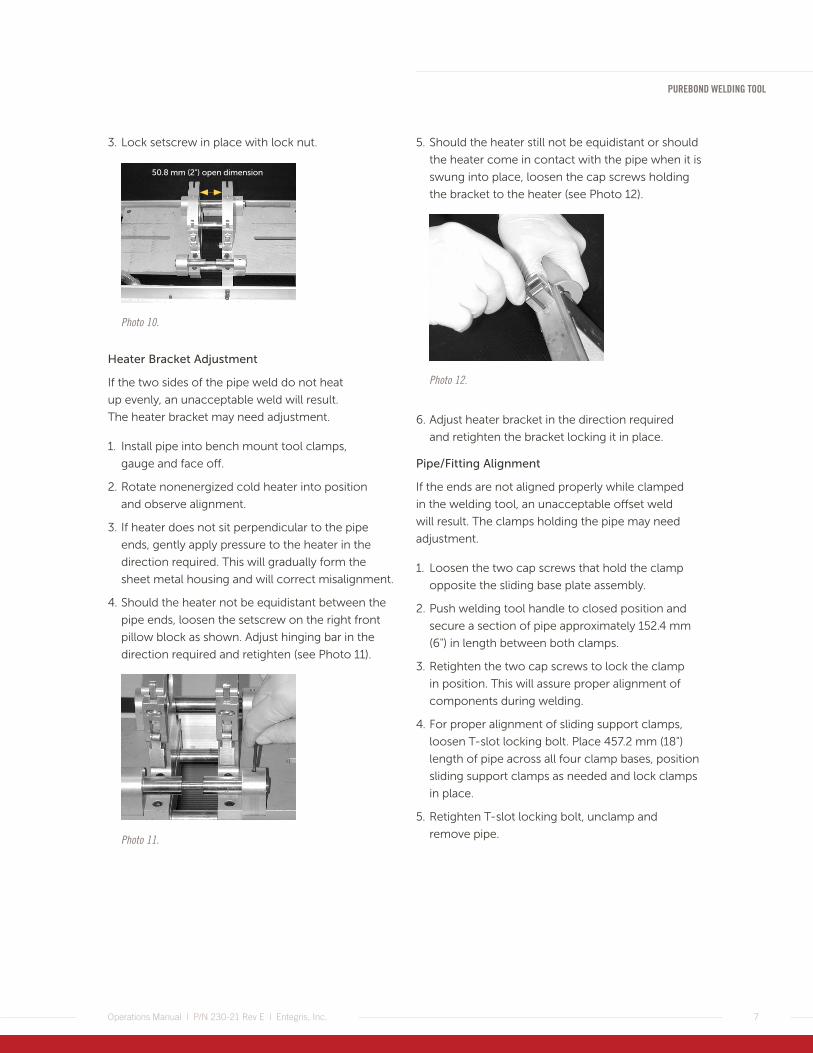
3. Lock setscrew in place with lock nut.
Photo 10.
50.8 mm (2") open dimension
Heater Bracket Adjustment
If the two sides of the pipe weld do not heat
up evenly, an unacceptable weld will result.
The heater bracket may need adjustment.
1. Install pipe into bench mount tool clamps,
gauge and face off.
2. Rotate nonenergized cold heater into position
and observe alignment.
3. If heater does not sit perpendicular to the pipe
ends, gently apply pressure to the heater in the
direction required. This will gradually form the
sheet metal housing and will correct misalignment.
4. Should the heater not be equidistant between the
pipe ends, loosen the setscrew on the right front
pillow block as shown. Adjust hinging bar in the
direction required and retighten (see Photo 11).
Photo 11.
5. Should the heater still not be equidistant or should
the heater come in contact with the pipe when it is
swung into place, loosen the cap screws holding
the bracket to the heater (see Photo 12).
Photo 12.
6. Adjust heater bracket in the direction required
and retighten the bracket locking it in place.
Pipe/Fitting Alignment
If the ends are not aligned properly while clamped
in the welding tool, an unacceptable offset weld
will result. The clamps holding the pipe may need
adjustment.
1. Loosen the two cap screws that hold the clamp
opposite the sliding base plate assembly.
2. Push welding tool handle to closed position and
secure a section of pipe approximately 152.4 mm
(6") in length between both clamps.
3. Retighten the two cap screws to lock the clamp
in position. This will assure proper alignment of
components during welding.
4. For proper alignment of sliding support clamps,
loosen T-slot locking bolt. Place 457.2 mm (18")
length of pipe across all four clamp bases, position
sliding support clamps as needed and lock clamps
in place.
5. Retighten T-slot locking bolt, unclamp and
remove pipe.

8
PUREBOND WELDING TOOL
Operations Manual | P/N 230-21 Rev E | Entegris, Inc.
WELDING STEPS—
STANDARD AND MINIMUM WELDS
For standard welds, use the standard width clamps
on either the 25.4 mm (1") or the 50.8 mm (2")
PureBond welding tool. These clamps are used for
general purpose welding and offer the best compo-
nent support. They should be used for joining long
and/or heavy lengths of pipe and fittings where
additional support is required.
The thin clamp assemblies, available only on the
25.4 mm (1") PureBond welding tool, will allow
users to significantly reduce the physical length
between fittings.
NOTE: Thin clamps are the only clamps suitable for welding 6.35 mm (1/4") pipe products.
Refer to “25.4 mm (1") PureBond Welding Tool with
Thin Clamps,” page 6, for thin clamp installation
instructions.
The facing and welding operations of the bench
mount tool with thin clamps are identical to the
standard clamp operation. There are, however,
slight differences in the fitting preparation and
gauging operation.
GAUGING USING STANDARD CLAMPS
1. Cut pipe to the desired length using the ratchet
style pipe shears provided (see Photo 13).
Photo 13.
2. Place the two parts that are to be welded into the
clamps and lock in place. Locking force can be
adjusted with thumb wheel. (To adjust the thumb
wheel, the clamp must be unlocked.)
3. 25.4 mm (1") Bench Mount
Place the proper size gauging tool — 12.7 mm (1⁄2"),
19.05 mm (3⁄4") or 25.4 mm (1") — between the two
parts to be welded and push the welding tool
handle closed. Use gauging tools for standard
clamps only.
50.8 mm (2") Bench Mount
Place the proper size gauging tool — 12.7 mm (1⁄2"),
19.05 mm (3⁄4"), 25.4 mm (1") or 50.8 mm (2")
between the two parts to be welded and push the
welding tool handle closed.
4. Adjust the pipe/fittings to make sure they are
inserted to full depth in the gauging tool, while
at the same time keeping the outer faces of
the gauging tool flush against the clamps (see
Photo 14).
Photo 14.
5. Tighten the clamps securely, release welding tool
handle and remove the gauging tool.
6. When fittings such as elbows and tees are involved,
be sure they are rotated to the proper orientation
(refer to page 11 – Capping Fittings/Pipe).
7. Gauging of the parts allows for a repeatable welded
assembly dimension. When welded, two parts will
be approximately 5.7 mm (0.224") closer than the
original length dimension.
GAUGING USING THIN CLAMPS
1. Prior to placing the fittings in the clamps, cut the
stub ends back using the special ratchet shears
provided (Part number 213-42). (See Photo 15.)
2. Each standard 12.7 mm (1⁄2"), 19.05 mm (3⁄4") and
25.4 mm (1") fitting has a shoulder that is approxi-
mately 38.1 mm (1.5") or 19.1 mm (0.75") from the
stub end. The special spacer plates on the side of
PUREBOND WELDING TOOL
9Operations Manual | P/N 230-21 Rev E | Entegris, Inc.
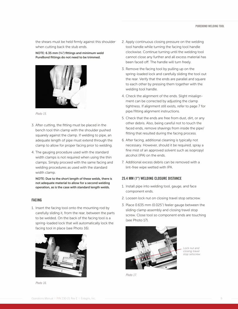
the shears must be held firmly against this shoulder
when cutting back the stub ends.
NOTE: 6.35 mm (1/4") fittings and minimum weld PureBond fittings do not need to be trimmed.
Photo 15.
3. After cutting, the fitting must be placed in the
bench tool thin clamp with the shoulder pushed
squarely against the clamp. If welding to pipe, an
adequate length of pipe must extend through the
clamp to allow for proper facing prior to welding.
4. The gauging procedure used with the standard
width clamps is not required when using the thin
clamps. Simply proceed with the same facing and
welding procedures as used with the standard
width clamp.
NOTE: Due to the short length of these welds, there is not adequate material to allow for a second welding operation, as is the case with standard length welds.
FACING
1. Insert the facing tool onto the mounting rod by
carefully sliding it, from the rear, between the parts
to be welded. On the back of the facing tool is a
spring-loaded lock that will automatically lock the
facing tool in place (see Photo 16).
Photo 16.
2. Apply continuous closing pressure on the welding
tool handle while turning the facing tool handle
clockwise. Continue turning until the welding tool
cannot close any further and all excess material has
been faced off. The handle will turn freely.
3. Remove the facing tool by pulling up on the
spring-loaded lock and carefully sliding the tool out
the rear. Verify that the ends are parallel and square
to each other by pressing them together with the
welding tool handle.
4. Check the alignment of the ends. Slight misalign-
ment can be corrected by adjusting the clamp
tightness. If alignment still exists, refer to page 7 for
pipe / fitting alignment instructions.
5. Check that the ends are free from dust, dirt, or any
other debris. Also, being careful not to touch the
faced ends, remove shavings from inside the pipe/
fitting that resulted during the facing process.
6. After facing, additional cleaning is typically not
necessary. However, should it be required, spray a
fine mist of an approved solvent such as isopropyl
alcohol (IPA) on the ends.
7. Additional excess debris can be removed with a
lint-free wipe wetted with IPA.
25.4 MM (1") WELDING CLOSURE DISTANCE
1. Install pipe into welding tool, gauge, and face
component ends.
2. Loosen lock nut on closing travel stop setscrew.
3. Place 0.635 mm (0.025") feeler gauge between the
sliding clamp assembly and closing travel stop
screw. Close tool so component ends are touching
(see Photo 17).
Photo 17.
Lock nut and closing travel stop setscrew
10
PUREBOND WELDING TOOL
Operations Manual | P/N 230-21 Rev E | Entegris, Inc.
4. Adjust setscrew to a position that allows the pipe
ends to touch and the 0.635 mm (0.025") shim to
be held snugly between the sliding clasp assembly
and closing travel stop screw. Tighten lock nut to
maintain adjustment.
If a weld has a very large bead or a sunken/concave
weld (see melt bead examples on page 12), the
welding closure distance may need adjustment.
50.8 MM (2") WELDING CLOSURE DISTANCE
1. Install pipe into bench mount tool clamp, gauge
and face component ends.
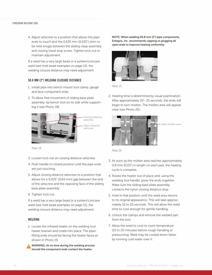
2. To allow free movement of sliding base plate
assembly, tip bench tool on its side while support-
ing it (see Photo 18).
Photo 18.
Closing distance setscrew
Open distance setscrew
3. Loosen lock nut on closing distance setscrew.
4. Push handle to closed position until the pipe ends
are just touching.
5. Adjust closing distance setscrew to a position that
allows for a 0.025" (0.64 mm) gap between the end
of the setscrew and the opposing face of the sliding
base plate assembly.
6. Tighten lock nut.
If a weld has a very large bead or a sunken/concave
weld (see melt bead examples on page 12), the
welding closure distance may need adjustment.
WELDING
1. Locate the infrared heater on the welding tool
heater bracket and rotate into place. The pipe/
fitting ends should be facing the heater faces as
shown in Photo 19.
WARNING: At no time during the welding process should the component ends contact the heater.
NOTE: When welding 50.8 mm (2") pipe components, Entegris, Inc. recommends capping or plugging all open ends to improve heating uniformity.
Photo 19.
2. Heating time is determined by visual examination.
After approximately 20 – 25 seconds, the ends will
begin to turn molten. The molten area will appear
clear (see Photo 20).
Photo 20.
Clear molten area
3. As soon as the molten area reaches approximately
0.8 mm (0.03") in length on each part, the heating
cycle is complete.
4. Rotate the heater out of place and, using the
welding tool handle, press the ends together.
Make sure the sliding base plate assembly
contacts the nylon closing distance stop.
5. Hold in that position until the weld area returns
to its original appearance. This will take approxi-
mately 15 to 20 seconds. This will allow the weld
time to cool enough for gentle handling.
6. Unlock the clamps and remove the welded part
from the tool.
7. Allow the weld to cool to room temperature
(15 to 20 minutes) before rough handling or
pressurizing. Weld may be cooled down faster
by running cold water over it.

PUREBOND WELDING TOOL
11Operations Manual | P/N 230-21 Rev E | Entegris, Inc.
SUPPORTING PIPE LENGTHS
Support long and/or heavy lengths of pipe and fit-
tings. Do not allow the bench mount welding tool
to act as the only support or part misalignment may
occur. Use the additional set of sliding support clamps
on the 50.8 mm (2") PureBond welding tool when
possible (see Photo 21). Putting the long, heavy side
of an assembly on the right, stationary side of the
welding tool also helps support the assembly and
facilitates external material supports.
Photo 21.
CAPPING FITTINGS/PIPE
If possible, avoid welding fittings and pipe that extend
vertically upward from the welding tool. This may
cause uneven heating. Orient these parts so the legs
point either to the side or downward. If this is not
possible, cover the opening in the vertical section.
PROTECTING VALVES
When welding valves using thin clamps, cover the
actuator with aluminum foil to reflect heat and
prevent melting the actuator housing. Actuators
must not be removed when welding valve bodies.
When welding pneumatic or manual sampling valves,
make certain to cap the open port to minimize heat
transfer to the closing orifice. Also note, manual
sampling valves are to remain in the open position
during welding.

12
PUREBOND WELDING TOOL
Operations Manual | P/N 230-21 Rev E | Entegris, Inc.
WELD INSPECTION AND QUALIFICATION—To qualify a weld, two inspections are required: visual
and flex. A weld is qualified if it passes both inspec-
tions as outlined below. Always perform a weld
qualification on the first weld each day to ensure that
the equipment is operating properly.
WELD VISUAL INSPECTION
Perform a visual inspection on 100 percent of welds.
1. Observe the weld area to verify that the distinctive
beads exist at the weld line, 360° around the pipe.
2. Compare the external melt bead to the examples
shown in Figure 1.
3. Check the weld area for a large number of air
bubbles. This is an indication of either dust/debris in
the weld or overheating.
4. If the weld does not display the required bead
around the pipe/fitting or exhibits a large number of
air bubbles, cut that area out, cool to room
temperature and weld again using the proper
procedures.
WELD FLEX INSPECTION
After performing weld flex inspection as instructed
below in Steps 1–5, repeat the inspection at the
beginning of each shift and with any operator change.
1. Cut the sample leaving 50.8 mm (2") of pipe on
either side of the weld.
2. Cut the pipe lengthwise sectioning the weld in
three equally wide strips. (When sectioning 50.8
mm [2"] pipe, each strip should be about 25.4 mm
[1"] wide.)
3. Bend the ends of the strip, as shown, once in each
direction to check the inside and outside of the
weld (see Photo 22).
4. Inspect the weld area. If there are any cracks or
voids evident, the weld is defective.
5. If the weld is faulty in appearance, check the
probable reason using the examples shown in
Figure 1 and make another weld.
CORRECT PROCEDURE EXAMPLES
Fitting to pipe Pipe to pipe
No misalignment No misalignment
No gaps or voids No gaps or voids
Two distinctive beads360° around joint
Two distinctive beads360° around joint
Figure 1. Melt bead examples.
PROBABLE REASONS FOR FAULTY JOINTS
Incomplete facing / uneven heating Overheating
Insufficient joining force Excessive joining force
Uneven external and internal melt bead
Large number of air bubbles in joint area
Melt bead one side only Excessively wide melt bead
Gap or void
Large external and internal melt bead
External and internal melt beads not properly formed
Gap or void
Photo 22.
PUREBOND WELDING TOOL
13Operations Manual | P/N 230-21 Rev E | Entegris, Inc.
DIMENSIONAL WELDING—Dimensional welding is the practice of building an
assembly to meet predetermined dimensions. Com-
monly done for plumbing installed on a skid or in a
cabinet, dimensional welding assumes the operator’s
ability to make acceptable welds and requires an
understanding of component dimensions, measuring,
and weld sequencing.
WELD TYPES
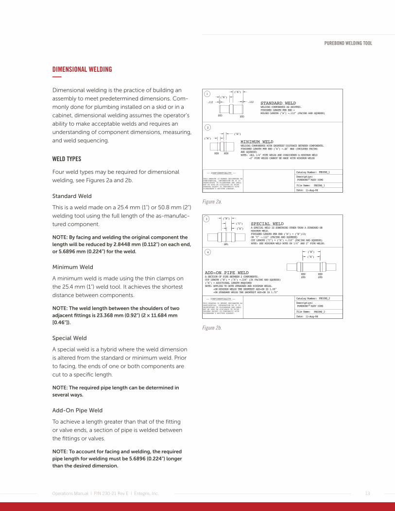
Four weld types may be required for dimensional
welding, see Figures 2a and 2b.
Standard Weld
This is a weld made on a 25.4 mm (1") or 50.8 mm (2")
welding tool using the full length of the as-manufac-
tured component.
NOTE: By facing and welding the original component the length will be reduced by 2.8448 mm (0.112") on each end, or 5.6896 mm (0.224") for the weld.
Minimum Weld
A minimum weld is made using the thin clamps on
the 25.4 mm (1") weld tool. It achieves the shortest
distance between components.
NOTE: The weld length between the shoulders of two adjacent fittings is 23.368 mm (0.92") (2 × 11.684 mm [0.46"]).
Special Weld
A special weld is a hybrid where the weld dimension
is altered from the standard or minimum weld. Prior
to facing, the ends of one or both components are
cut to a specific length.
NOTE: The required pipe length can be determined in several ways.
Add-On Pipe Weld
To achieve a length greater than that of the fitting
or valve ends, a section of pipe is welded between
the fittings or valves.
NOTE: To account for facing and welding, the required pipe length for welding must be 5.6896 (0.224") longer than the desired dimension.
Figure 2a.
Figure 2b.

14
PUREBOND WELDING TOOL
Operations Manual | P/N 230-21 Rev E | Entegris, Inc.
COMPONENT DIMENSIONS
All four weld styles use the shoulder on the fitting or
valve end as the measuring starting point. Entegris’
Fluid Handling Products Catalog shows the overall
dimension for all fittings, valves, pipe sizes, and
miscellaneous components. Visit www.entegris.com
for specific information.
Generally speaking, the PureBond component stubs
(the length on the end of all fittings and valves between
the end and the shoulder) are the same lengths for all
components with the same outside diameter.
WELD SEQUENCING
When welding complex shapes, it is very important
to plan your work. Without adequate forethought,
it is possible to get to a position that the weld simply
cannot be made. The most common oversights are:
• trying to weld two subassemblies with shapes
that cannot be clamped into the welding tool
• trying to weld two subassemblies but damaging
the structure with the heater
WELDING TIPS
• Be sure to note valve and filter housing inlet
and outlet orientation.
• When possible, weld big, heavy components
such as filter housings, tanks, large valves, and
ANSI flanges last.
• For tight “U" assemblies, weld the two halves
of the “U" last
HELPFUL HINTS
Consider the following helpful hints during the
fabrication of a pipe system.
1. Prior to actually welding PureBond pipe compo-
nents, check to see that the tools are adjusted
properly. To do this, simulate the actual process
before energizing the heater. Simply gauge,
face-off, and rotate the heater into place. Check
that the heater does not come into contact with
the pipe/fitting and that an equal spacing exists
on either side of the heater. If an adjustment is
necessary, refer to the Tool Maintenance section
on page 4.
2. Always perform a Weld Qualification on the first
weld each day to ensure the equipment is operat-
ing properly (see page 12).
3. All infrared heaters require connection to the
exact rated voltage (i.e., 100, 120, 230 VAC). If
possible, connect to a voltage that is within ±5%
of rating.
4. If possible, avoid welding fittings and pipe that
extend vertically upward from the welding tool.
This may cause uneven heating on the pipe/fittings
ends. Instead, orient these parts so the legs point
either to the side or downward. If this is not
possible, cover the opening in the vertical section.

PUREBOND WELDING TOOL
15Operations Manual | P/N 230-21 Rev E | Entegris, Inc.
WELDED SYSTEM REQUIREMENTS—
INSTALLED PIPE SUPPORT
To provide trouble-free service and minimize the
stress and strain put on the pipe wall, long lengths
of Pure Bond weldable pipe must be supported. The
minimum recommended distance between pipe
supports was calculated by taking into account the
weight of the pipe, its contents and an allowable
stress. As shown in Table 1, the distance between
supports is also affected by pipe size and temperature.
Table 1.
Size 23°C (73°F) 100°C (212°F) 177°C (350°F)
6.35 mm (1⁄4")
68 cm (26.9")
55 cm (21.5")
37 cm (14.5")
12.7 mm (1⁄2")
82 cm (32.4" )
67 cm (26.4")
46 cm (18.0")
19.05 mm (3⁄4")
91 cm (36.0")
73 cm (28.8")
49 cm (19.2")
25.4 mm (1")
101 cm (39.6")
79 cm (31.2")
55 cm (21.6")
50.8 mm (2")
122 cm (48.0")
98 cm (38.4")
64 cm (25.2")
The specific gravity of a fluid in excess of 1.0 can
adversely affect the pipe support spacing. The
recommended spacing distance should be multiplied
by the factor indicated in Table 2, resulting in shorter
distances between supports.
Table 2.
Specific Gravity Factor
1.00 1.00
1.25 0.94
1.50 0.89
1.75 0.86
2.00 0.82
2.25 0.79
2.50 0.76
2.75 0.74
3.00 0.72
NOTE: These recommendations are intended to ensure the pipe will function to specification. Sagging between hangers may occur. To avoid sagging, the pipe should be continuously supported.
The pipe supports specified should not be the type
that clamp the pipe tightly and restrict movement,
especially when thermal expansion and contraction
is involved. By not using this type of clamp, you will
prevent abrading and damaging the pipe wall. An
alternative to intermittent pipe supports is to continu-
ously support the pipe by laying it in a trough. Com-
monly extruded shapes such as angles, channel, and
conduit work well as a trough.
Vertical sections of pipe, referred to as risers, must
also be supported. The top and base of the risers
should always be supported in addition to having
brackets at 1.5 m (5') vertical intervals.
Accessory items such as valves, filter housings, etc.,
should not be fully supported by the pipe. Individual
supports should be specified for all heavy compo-
nents connected to a pipe system.
16
PUREBOND WELDING TOOL
Operations Manual | P/N 230-21 Rev E | Entegris, Inc.
THERMAL EXPANSION AND CONTRACTION
Thermal expansion and contraction of PureBond
weldable pipe should be considered during the
design and installation stages of a pipe system. If the
working temperature is higher than the installation
temperature the pipe becomes longer. If the working
temperature is lower than the installation temperature
the pipe will become shorter. Consequently, the
installation temperature as well as the maximum and
minimum working temperatures must be considered
when designing a system. One common guideline is
to install the pipe when it is within -12.22°C to
-9.44°C (10°F to 15°F) of its operating temperature.
When this is not practical, thoroughly examine the
pipe layout.
Small length changes can be tolerated by the pipe
because of its modulus of elasticity and inherent
property of stress relaxation of PFA. When large
changes are present, they should be compensated for
in the pipe layout. To determine the amount of length
change, a formula is used that takes into account the
coefficient of linear thermal expansion of the specific
material (see Formula 1).
Formula 1 – Accommodations for Thermal Expansion
ΔL = L•ΔT•C
Where:
ΔL = Length change, inches
L = Original length, inches
ΔT = Change in temperature, °C (°F)
C = Coefficient of thermal expansion,
In/In/°C (°F) for PFA
21.11°C – 100°C (70°– 212°F) = 6.7 × 10⁻⁵
100°C – 148.89°C (212°– 300°F) = 9.4 × 10⁻⁵
148.89°C – 208.89°C (300°– 408°F) = 11.1 × 10⁻⁵
An easy rule of thumb for estimating the length
change is to assume that for every -12.22°C (10°F)
change, a change of one inch will occur in any
30.48 m (100 foot) linear length. When substantial
length changes are evident, they must be compen-
sated for by the use of flexible sections, expansion
loops, expansion welds, etc. If this is a concern in
your pipe system, contact Entegris for advice in
properly incorporating these options.
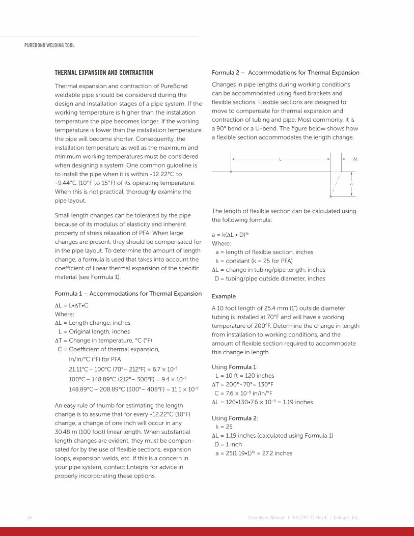
Formula 2 – Accommodations for Thermal Expansion
Changes in pipe lengths during working conditions
can be accommodated using fixed brackets and
flexible sections. Flexible sections are designed to
move to compensate for thermal expansion and
contraction of tubing and pipe. Most commonly, it is
a 90° bend or a U-bend. The figure below shows how
a flexible section accommodates the length change.
The length of flexible section can be calculated using
the following formula:
a = k(ΔL • D)1/2
Where:
a = length of flexible section, inches
k = constant (k = 25 for PFA)
ΔL = change in tubing/pipe length, inches
D = tubing/pipe outside diameter, inches
Example
A 10 foot length of 25.4 mm (1") outside diameter
tubing is installed at 70°F and will have a working
temperature of 200°F. Determine the change in length
from installation to working conditions, and the
amount of flexible section required to accommodate
this change in length.
Using Formula 1:
L = 10 ft = 120 inches
ΔT = 200° - 70°= 130°F
C = 7.6 × 10 - 5 in/in/°F
ΔL = 120•130•7.6 × 10 - 5 = 1.19 inches
Using Formula 2:
k = 25
ΔL = 1.19 inches (calculated using Formula 1)
D = 1 inch
a = 25(1.19•1)1/2 = 27.2 inches
×
a
L
×
L
PUREBOND WELDING TOOL
17Operations Manual | P/N 230-21 Rev E | Entegris, Inc.
MODIFYING A WELDED SYSTEM—
REWELDING BEFORE COMMISSIONING
Except when minimum weld clamps are used, a
butt weld can be easily cut out of a PureBond pipe
component and remade. Entegris designed PureBond
fittings to be welded more than once, if necessary,
so the fitting does not need to be discarded.
REWELDING AFTER COMMISSIONING
Although rewelding after commissioning may be
possible when certain fluids are used, Entegris
generally does not recommend rewelding used
components. To discuss this further, contact your
local Entegris distributor or Entegris, Inc.
SAFETY CONSIDERATIONS DURING WELDING AND AFTER INSTALLATION—
MATERIAL INFORMATION
In the last half century, experience has shown
that no reported cases of serious injury, prolonged
illness, or death have resulted from the handling of
fluoropolymer resins. Tests further indicate that the
resins may be taken in food without ill effect, and that
the resins are non irritating and nonsensitizing to the
skin. There have been no known instances of dermati-
tis, allergy, or other ill effects caused by handling
unheated fabricated forms of material resins.
In the case of human exposure to heated fluoropoly-
mer resins, no lethal effect has been observed.
Instead, such exposure has merely caused a tempo-
rary flu-like condition called Polymer Fume Fever. The
symptoms do not ordinarily occur until about two or
more hours after exposure and pass off within 36 to
48 hours, even in the absence of treatment. Observa-
tions indicate that these attacks have no lasting effect
and that the effects are not cumulative.
When such an attack occurs, it usually follows
exposure to vapors evolved from the polymer at
high temperatures used in resin processing opera-
tions. PFA processing and welding are examples of
operations during which vapors can be liberated.
To verify that there is no lethal effect of exposure to
heated fluoropolymer resins, an investigation was
made by an independent laboratory into the potential
for generation of fluoride decomposition products
during welding. Air samples were collected for one
hour directly above the weld point to determine if any
particulate or gaseous decomposition products were
being generated.
The testing was done in stagnant air to simulate
worst-case conditions. No decomposition products,
measured as hydrolyzable fluoride, were detected
during this time. The lower detection limit of this
test was 0.3 parts per million. These test results
show that there is little potential for generation of
hazardous decomposition products during the
normal welding process.

18
PUREBOND WELDING TOOL
Operations Manual | P/N 230-21 Rev E | Entegris, Inc.
WARNING
As a matter of good industrial practice, we strongly
urge you to practice proper ventilation to eliminate
this potential problem and the resultant operator
discomfort. Questions about ventilation in cases of
processing, welding, or other applications at tempera-
tures at or above 200°C (392°F) should be directed to
Entegris. To further safeguard against the potential
discomforts of Polymer Fume Fever, do not smoke
tobacco while processing, welding, or flaring PFA
material. This will reduce the possibility of inhaling
any decomposition products, although small in
quantity that may be over-heated by drawing them
though a lit cigarette.
Entegris has strategically placed warning labels on
the welding tool. Please be advised and aware of
these warnings.
HEATING ELEMENT SAFETY
Since PFA has a very high melting point, it is necessary
to exceed that temperature to weld. The heating
element’s white quartz face and metal supports are
very hot—over 537.78°C (1000°F)! Handle it with care
and only by the handle. When not in use, the heating
element should be placed in its holder/heat shield,
well away from combustible materials. Ensure the
holder/heat shield has a minimum of 610 mm (24")
space above to allow for proper heat dissipation. The
230 VAC heater is CE marked per Low Voltage
Directive 73 /23/EEC (EN60335-1 and EN60335-2-45).
The heating element takes a long time to cool after
being unplugged. On average, allow the heating
element to cool for an hour before handling
or packing.
WELD COOLING
PFA conducts heat very slowly. The new weld is
strong enough to be moved and support its own
weight approximately 15 – 20 seconds after welding.
However, the weld area will be hot enough to burn
flesh for about 1 minute.
The new weld will cool to room temperature and
have full strength in 15 – 20 minutes.
WARNING: To prevent burns, DO NOT touch the weld area during cooldown.
ELECTRICAL SHOCK
As with any electrical device, the heating element has
the potential for delivering an electrical shock. Take
normal care to be sure the plug, power cord, and
heating element are kept in good repair. Entegris does
not recommend use around water or other liquids.
INSTALLED SYSTEM SAFETY
All PureBond components have operational ratings.
These ratings were developed through extensive
testing. Entegris does not recommend that an
installed system be operated in excess of the pub-
lished ratings. Ratings and test procedures can be
found in Entegris’ Fluid Handling Products Catalog.
Visit www.entegris.com for specific information.
Although PFA is a very tough material, Entegris does
not recommend that heavy objects be supported by
the PureBond welded system.
PUREBOND WELDING TOOL
19Operations Manual | P/N 230-21 Rev E | Entegris, Inc.
TECHNICAL INFORMATION—
CREEP RESISTANCE
One important determination in designing a pipe
system is to specify a material that exhibits a low
creep rate at the intended stress. Of all the fully
fluorinated fluoropolymers, PFA displays the highest
resistance to creep.
At room temperature with a stress of 500 psi, the
degree of creep after 10,000 hours is 1.2%. Similarly,
at 100°C (212°F) the creep rate measures 4%. Even
at 200°C (392°F) the creep rate is only 6.3%. This is
important because a high creep rate should be
avoided and may result in unpredictable and prema-
ture failures.
LONG-TERM PIPE STRENGTH
The long-term hydrostatic strength of PFA used in
PureBond pipe was determined in accordance with
the test procedures outlined in ASTM D2837, Obtain-
ing Hydrostatic Design Basis for Thermoplastic Pipe
Materials. This analysis has assigned a 100,000 hour
long-term strength value of 1600 psi at 23°C (73°F)
for PureBond pipe.
The following is a simplified summary of how this
value was determined.
1. PFA pipe specimens are subjected to constant
internal water pressure at different pressure levels
and the time-to-rupture is measured. Stress on
each specimen is calculated from the pressure by
means of a pipe design equation.
Formula 3:
S = P(D-t)
2t
Where: S = Stress, psi
P = Pressure, psig
D = Average outside diameter, inches
t = Minimum wall thickness, inches
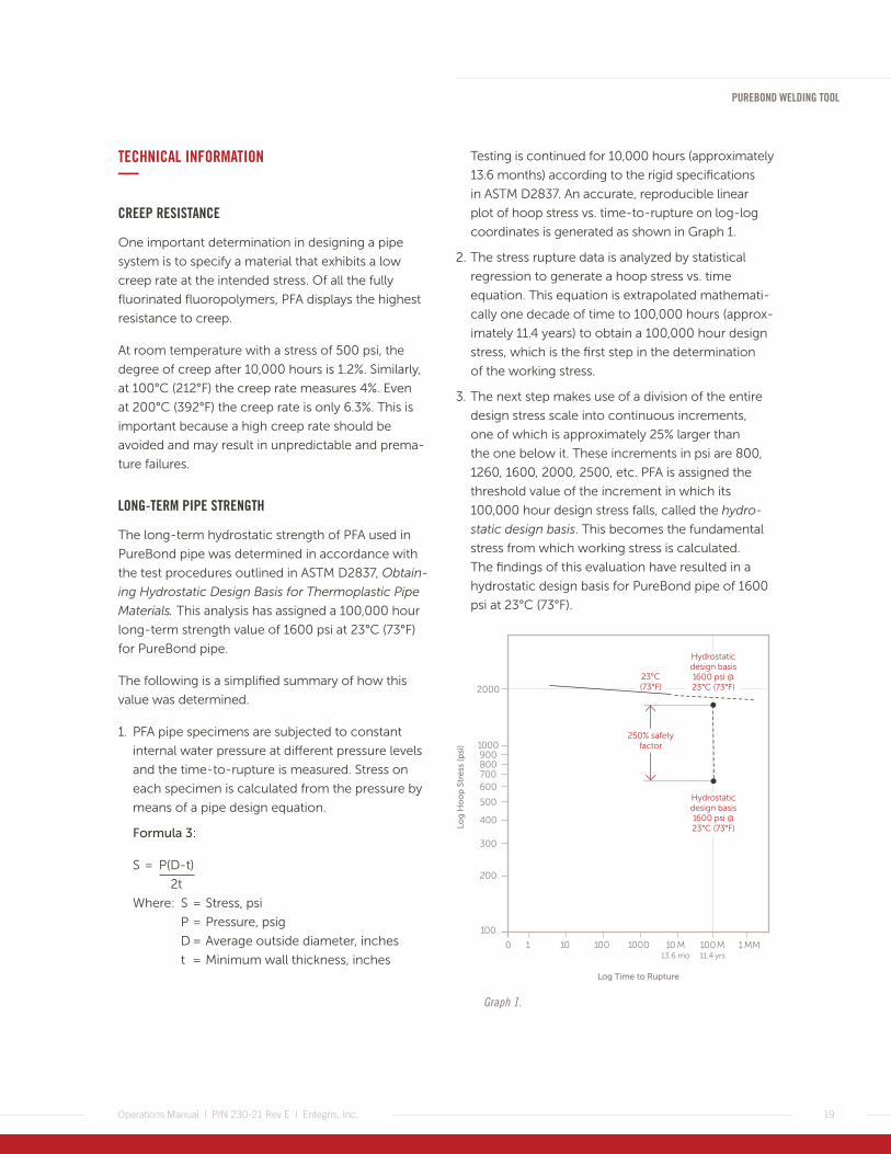
Testing is continued for 10,000 hours (approximately
13.6 months) according to the rigid specifications
in ASTM D2837. An accurate, reproducible linear
plot of hoop stress vs. time-to-rupture on log-log
coordinates is generated as shown in Graph 1.
2. The stress rupture data is analyzed by statistical
regression to generate a hoop stress vs. time
equation. This equation is extrapolated mathemati-
cally one decade of time to 100,000 hours (approx-
imately 11.4 years) to obtain a 100,000 hour design
stress, which is the first step in the determination
of the working stress.
3. The next step makes use of a division of the entire
design stress scale into continuous increments,
one of which is approximately 25% larger than
the one below it. These increments in psi are 800,
1260, 1600, 2000, 2500, etc. PFA is assigned the
threshold value of the increment in which its
100,000 hour design stress falls, called the hydro-
static design basis. This becomes the fundamental
stress from which working stress is calculated.
The findings of this evaluation have resulted in a
hydrostatic design basis for PureBond pipe of 1600
psi at 23°C (73°F).
Hydrostaticdesign basis1600 psi @ 23°C (73°F)
1000
2000
900800700600
500
400
300
200
0 1 10 100 1000 1 MM
Log Time to Rupture
Log
Ho
op
Str
ess
(psi
)
100
23°C (73°F)
250% safetyfactor
Hydrostaticdesign basis1600 psi @ 23°C (73°F)
10 M13.6 mo
100 M11.4 yrs
Graph 1.
20
PUREBOND WELDING TOOL
Operations Manual | P/N 230-21 Rev E | Entegris, Inc.
SAFETY FACTOR FOR PIPE
The PureBond pipe product line has been developed
with the end user's safety in mind. The manufacture
of the pipe, fittings and related components, and the
quality assurance measures taken ensure you the
utmost in system integrity. To compensate for the
number of variables involved in each application, a
safety (design) factor has been incorporated. This
allows for:
• Occasional pressure surges/water hammer
• Improper pipe installation and/or support, to
some extent
• Stresses due to thermal expansion and contraction
• Longitudinal stresses in the pipe
The hydrostatic stress committee of the Plastic Pipe
Institute (PPI) recommends a minimum safety (design)
factor of 200% based on the hydrostatic design basis.
Keeping in mind the severity of the applications in
which the PureBond pipe products will be used,
Entegris, Inc. feels that a Safety Factor of 250%
would better accommodate these types of services.
Therefore, the hydrostatic design stress would be:
HDS = 1600 psi
2.5
HDS = 640 psi
The hydrostatic design stress is defined as the
maximum hoop stress in the pipe wall due to internal
hydrostatic pressure that can be applied continuously
with a high degree of certainty that pipe failure will
not occur within a long period of time. A service life
of 50 years is generally accepted as the minimum for
a pipe system evaluated in this manner.
WELD STRENGTH
The PureBond pipe components are joined by a butt
weld. This style of connection has proven itself for
many years as strong and safe. Entegris chose the
butt weld for PureBond pipe components for many
reasons, some of which include:
• The internal contour of a butt weld has only
one small melt bead. Large obstructions and
voids that can trap particulate and restrict flow
are not present.
• The PureBond butt welding technique is a fast,
simple, visual procedure with straightforward
instructions. The variables typically associated with
welding pipe have been addressed in the welding
tool designs. The noncontact, noncontaminating
heater provides consistent high-quality welds.
• The butt weld configuration is a structurally sound
connection. By design, the stresses initiated by pipe
deflection are dispersed throughout the pipe rather
than concentrated at the weld.
• The PureBond weld does not affect the safety
factor or ratings of the pipe, fittings, valves, or
other components. This has been evidenced by
the following tests conducted at 23°C (73°F).
PUREBOND WELDING TOOL
21Operations Manual | P/N 230-21 Rev E | Entegris, Inc.
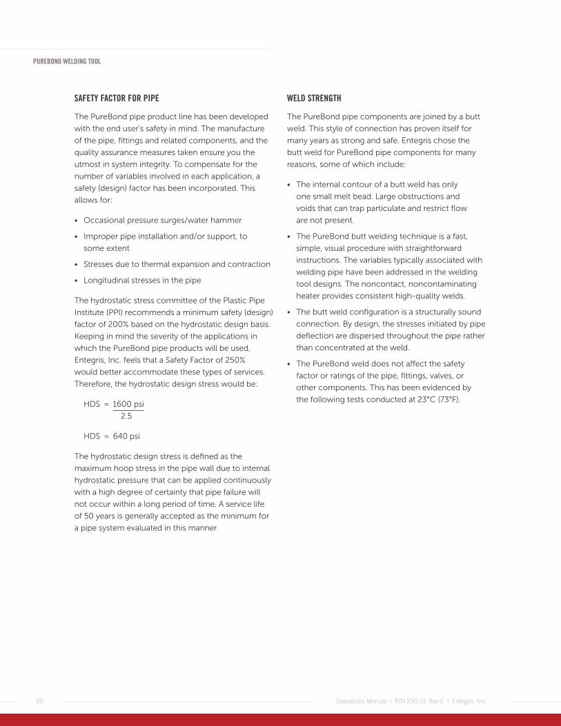
SHORT-TIME BURST
ASTM D1599, Short-time Hydraulic Failure Pressure of
Plastic Pipe, Tubing and Fittings. This standard calls for
pressurizing the specimens in a uniform and continu-
ously increasing manner until failure occurs (see
Photo 23). Failure must occur between 60 to 70
seconds. Many specimens of each size (12.7 mm [1⁄2"],
19.05 mm [3⁄4"], and 25.4 mm [1"]) were evaluated and
in all cases the welds proved to be fully resistant to
failure. The average failure pressures are as follows:
6.35 mm (1⁄4") 71 bar (1030 psig)
12.7 mm (1⁄2") 51 bar (741 psig)
19.05 mm (3⁄4") 42 bar (608 psig)
25.4 mm (1") 36 bar (529 psig)
50.8 mm (2") 24 bar (357 psig)
Photo 23.
CYCLIC SHOCK TEST
In addition to all sizes of pipe and welded fittings, the
welds are fully resistant to failure in excess of one
million cycles, to a cyclic pressure of 0 – 12.9 bar
(0 – 187 psig) at a rate of 30 cycles per minute.
TENSILE TEST
An Instron tensile pull test was conducted on many
specimens of 12.7 mm (1⁄2"), 19.05 mm (3⁄4"), and 25.4
mm (1") PureBond welded pipe in an effort to separate
the weld. At a rate of one-inch pull per minute, no
weld failures were experienced. The maximum
amount of pull at failure is recorded as follows:
6.35 mm (1⁄4") 110 kg (243 lb)
12.7 mm (1⁄2") 228 kg (502 lb)
19.05 mm (3⁄4") 307 kg (676 lb)
25.4 mm (1") 441 kg (973 lb)
These test results are only useful in predicting the
behavior of pipe and fittings, and should not be used
as long-term ratings. To achieve these results, adhere
to the proper welding procedures for PureBond pipe
components.

22
PUREBOND WELDING TOOL
Operations Manual | P/N 230-21 Rev E | Entegris, Inc.
DEFINITIONS—Component end – that part of a weldable fitting,
valve, or pipe that is suitable for PureBond welding.
Creep – the change in shape caused by an internally
or externally applied stress.
Dimensional welding – the practice of building an
assembly to meet a predetermined dimension.
Facing – the process of preparing the components
to be welded by shaving off their ends with a special
tool.
Flexible section – the portion of a welded system,
generally perpendicular to the main run, that accom-
modates the thermal expansion/contraction of the
pipe system.
Gauging – the process of correctly positioning the
components in the welding tool.
Heater – the infrared heat source used to melt PFA
for welding. For better cleanliness, the white face of
the heater is quartz and, therefore, breakable.
CAUTION: The heater reaches temperatures greater than 537.78°C (1000°F).
Minimum weld – made using the thin clamps on
the 1" welding tool. A minimum weld achieves the
shortest distance between components.
Polymer Fume Fever – the temporary flu-like condi-
tion occasionally caused by exposure to vapors from
high-temperature PFA. Smoking while welding
enhances the possibility of experiencing polymer
fume fever.
Shoulder – the step on the outside of the fitting or
valve where the component’s main body meets the
pipe dimensioned end.
Special weld – a weld made with at least one of
the components being cut and faced to a specified
length.
Thermal expansion – the change in a pipe (or other
component) length resulting from heating or cooling
it. PFA thermal expansion is considerably greater than
stainless steel thermal expansion.
Thin clamps – thin clamps replace the standard
clamps on the 1" welding tool and are used to hold
the components during the welding process. The thin
clamps allow minimum welding.
Weld – the junction of two welded components.
Welding – the process of simultaneously heating
both ends of the components and then pressing
the molten ends together.
Welding closure distance – sometimes referred
to as the “squeeze," this is the amount the molten
components are allowed to overlap during the joining
process. It is measured as the distance from the inside
edge of the sliding clamp side to the travel stop
setscrew while the tool is closed. This distance is
0.635 mm (0.025").


129 Concord RoadBillerica, MA 01821 USA
Tel +1 952 556 4181Fax +1 952 556 8022Toll Free 800 394 4083
Corporate Headquarters Customer Service
FOR MORE INFORMATION
Please call your Regional Customer Service Center today to learn what Entegris can do for you. Visit entegris.com and select the Contact Us link to find the customer service center nearest you.
TERMS AND CONDITIONS OF SALE
All purchases are subject to Entegris’ Terms and Conditions of Sale. To view and print this information, visit entegris.com and select the Terms & Conditions link in the footer.
LIMITED WARRANTY
Entegris' products are subject to the Entegris, Inc. General Limited Warranty. To view and print this information, visit entegris.com and select the Legal & Trademark Notices link in the footer. Entegris does not warranty any failure in the case of customers using unapproved foreign components.
www.entegris.com
Entegris®, the Entegris Rings Design™, Pure Advantage™, and other product names are trademarks of Entegris, Inc. as listed on entegris.com/trademarks. All third-party product names, logos, and company names are trademarks or registered trademarks of their respective owners. Use of them does not imply any affiliation, sponsorship, or endorsement by the trademark owner.
©2004-2017 Entegris, Inc. | All rights reserved. | Printed in the USA | 3130-1575ENT-1117
Operations Manual | P/N 230-21 Rev E | Entegris, Inc.


![Entegris Corp Presentation Aug2011.ppt › docs › ENTEGRIS corporate-overview websit… · Microsoft PowerPoint - Entegris Corp Presentation Aug2011.ppt [Compatibility Mode] Author:](https://static.fdocuments.in/doc/165x107/5f1e5777e8ddf208aa619e4f/entegris-corp-presentation-a-docs-a-entegris-corporate-overview-websit-microsoft.jpg)