Pumping station modification.pdf
15
PUMPING STATION MODIFICATIONS TO COMPLY WITH ANSI/HI 9.8 IMPROVE PERFORMANCE WHILE LESSENING O&M REQUIREMENTS --- TWO CASE STUDIES Allen P. Sehloff*, Glen Curtis**, Rick Henry***, Rex Huttes****, Garr Jones*****, Don Song***** *Brown and Caldwell 30 East 7 th Street, Suite 2500 St. Paul, MN 55101 **Monroe County Department of Environmental Services, Rochester, New York ***Clark Patterson Associates, Rochester, New York ****Metropolitan Council Environmental Services, St. Paul, Minnesota *****Brown and Caldwell ABSTRACT Oversized wet wells in wastewater pumping stations lead to the accumulation of grit, sludge and floatable materials. Trench-type wet wells in compliance with ANSI/HI 9.8, the American National Standard for Pump Intake Design, minimize wet well volume and facilitate wet well cleaning through periodic pump down operations. Two pumping stations, the Cross-Irondequoit Pump Station (CIPS), Monroe County, New York, and the Metropolitan Council Environmental Services (MCES) L-65 Lift Station, South St. Paul, Minnesota, were modified to more closely comply with ANSI/HI 9.8. Both stations were initially constructed in the 1970s, prior to the adoption of ANSI/HI 9.8 as a consensus standard. In addition to the wet well modifications, four of the original pumps at the CIPS were removed and replaced with new pumps with improved foundations to address vibration problems and provided with revised suction piping to comply with the pump inlet requirements of ANSI/HI 9.8. The L-65 Lift Station underwent a complete renovation, with all pumps, piping, electrical and mechanical systems upgraded while keeping the lift station in service at all times during construction. Modifications to the wet well and the improved pump foundations have eliminated grit accumulation and vibration problems at CIPS. The trench-type wet well provided at L-65 has been used by MCES operations staff during pump down operations to fluidize and remove floatables that accumulate on the wet well, greatly simplifying cleaning operations. KEYWORDS ANSI/HI 9.8, consensus standard, pump intake, trench-type wet well, variable speed, vibration, wastewater INTRODUCTION There have been significant changes in the design of pumping station wet wells and pump intakes over the last 20 years, most notably the adoption of ANSI/HI 9.8, the American National 2143 WEFTEC®.06 Copyright 2006 Water Environment Foundation. All Rights Reserved ©
-
Upload
carlosnavalmaster -
Category
Documents
-
view
76 -
download
2
Transcript of Pumping station modification.pdf

PUMPING STATION MODIFICATIONS TO COMPLY WITH ANSI/HI 9.8 IMPROVE PERFORMANCE WHILE
LESSENING O&M REQUIREMENTS --- TWO CASE STUDIES
Allen P. Sehloff*, Glen Curtis**, Rick Henry***, Rex Huttes****, Garr Jones*****, Don Song*****
*Brown and Caldwell
30 East 7th Street, Suite 2500 St. Paul, MN 55101
**Monroe County Department of Environmental Services, Rochester, New York ***Clark Patterson Associates, Rochester, New York
****Metropolitan Council Environmental Services, St. Paul, Minnesota *****Brown and Caldwell
ABSTRACT Oversized wet wells in wastewater pumping stations lead to the accumulation of grit, sludge and floatable materials. Trench-type wet wells in compliance with ANSI/HI 9.8, the American National Standard for Pump Intake Design, minimize wet well volume and facilitate wet well cleaning through periodic pump down operations. Two pumping stations, the Cross-Irondequoit Pump Station (CIPS), Monroe County, New York, and the Metropolitan Council Environmental Services (MCES) L-65 Lift Station, South St. Paul, Minnesota, were modified to more closely comply with ANSI/HI 9.8. Both stations were initially constructed in the 1970s, prior to the adoption of ANSI/HI 9.8 as a consensus standard. In addition to the wet well modifications, four of the original pumps at the CIPS were removed and replaced with new pumps with improved foundations to address vibration problems and provided with revised suction piping to comply with the pump inlet requirements of ANSI/HI 9.8. The L-65 Lift Station underwent a complete renovation, with all pumps, piping, electrical and mechanical systems upgraded while keeping the lift station in service at all times during construction. Modifications to the wet well and the improved pump foundations have eliminated grit accumulation and vibration problems at CIPS. The trench-type wet well provided at L-65 has been used by MCES operations staff during pump down operations to fluidize and remove floatables that accumulate on the wet well, greatly simplifying cleaning operations. KEYWORDS ANSI/HI 9.8, consensus standard, pump intake, trench-type wet well, variable speed, vibration, wastewater INTRODUCTION
There have been significant changes in the design of pumping station wet wells and pump intakes over the last 20 years, most notably the adoption of ANSI/HI 9.8, the American National
2143
WEFTEC®.06
Copyright 2006 Water Environment Foundation. All Rights Reserved©

Standard for Pump Intake Design, as a consensus standard. This standard addresses wet well configurations and intake design for both clear and solids-bearing liquids. For new construction, a trench-type wet well with a protected inlet, as shown in Figure 1, is recommended for large stations with several pumps. This configuration facilitates wet well cleaning and minimizes the potential for pump damage by large debris. Cleaning of the wet well is accomplished by selectively operating the pump farthest from the inlet to lower the wet well level. A hydraulic jump forms on the acceleration ramp at the wet well inlet as the level is lowered, thereby fluidizing floatables. As the wet well level is lowered, this hydraulic jump travels along the wet well floor from the inlet to the last pump, scouring grit off the floor of the trench. The cleaning cycle ends when the pump breaks suction. The trench type wet well also provides proper approach conditions at the pump inlet bell, minimizing floor currents and swirl in the wet well that could contribute to vortexing and unbalanced operation. Many older wastewater pumping stations do not have a trench-type configuration or a protected inlet, resulting in the accumulation of debris that can clog or damage pumps and that can be difficult to remove. Two case studies, the Cross-Irondequoit Pump Station in Monroe County, New York, and the Metropolitan Council Environmental Services (MCES) L-65 Lift Station, South St. Paul, Minnesota, demonstrate how modifications to existing wastewater pumping stations can improve performance and reduce operation and maintenance costs by implementing ANSI/HI 9.8 improvements. CROSS-IRONDEQUOIT PUMP STATION The Cross-Irondequoit Pump Station (CIPS) serves as the influent pumping station for the Frank E. VanLare Wastewater Treatment Facility (VanLare WTF) in Monroe County, New York. The CIPS was constructed in the late 1970s as part of the 16-foot diameter, 28,000 foot long, Cross-Irondequoit Interceptor Tunnel and began operation in 1978. The tunnel provides both conveyance of wastewater to the VanLare WTF under normal conditions and storage during peak wet weather flow events. In addition to serving as the influent pumping station for the VanLare WTF, the CIPS is used to periodically pump down the tunnel to remove solids. The CIPS was constructed with a nominal capacity of 275 million gallons per day (mgd) provided by nine pumps with
Figure 1 - Trench Type Wet Well per ANSI/HI 9.8
Courtesy of Hydraulic Institute, Parsippany, NJ; www.pumps.org
2144
WEFTEC®.06
Copyright 2006 Water Environment Foundation. All Rights Reserved©

provisions for five additional pumps, served by two identical wet wells as shown in Figure 2. Each wet well has a trapezoidal shaped footprint, tapered from the exit of the inlet channels at the south, to the suction inlets for the smaller pumps, located at the extreme north end of the structure. Each wet well has been provided with positions for connection to seven dry pit bottom suction horizontal discharge wastewater pumps (Figure 2). There is an abrupt transition from elevation 204.0 to elevation 194.5 at the wet well inlets. A trench was provided in the vicinity of the pump intake locations that extends from the screen channel exit to the last large pump intake. Fillets along the common wall between the two wet wells provide some relief from the accumulation of heavy material such as grit and organic objects brought into the station with the incoming flow. The wet well invert for the large pump intakes (Pumps P-5, -7, -9, -11, and -13 on the west wet well and Pumps P-6, -8, -10, -12, and -14 on the east) slopes from elevation 194.5 at the exit of the screen channels to elevation 193.5 at the sump for the small pumps at the north end of the wet well. An abrupt transition to elevation 183.5 provides a pocket for the intakes for Pumps P-1 and -3 on the west and Pumps P-2 and -4 on the east. Pumps P-10 through P-14 are future units that may never be installed.
There were four variable speed 800 horsepower (hp) pumps and five constant speed 1,500 hp pumps, with room for an additional five constant speed pumps. The five 1,500 hp pumps are used during wet weather flows and with the exception of some minor instrumentation and controls improvements, were not addressed under this project. The dry weather average daily flow is approximately 20 mgd. The four 800 hp pumps (P-1 through P-4) were used to convey this flow to the VanLare WTF under normal operating conditions. Each of the two wet wells at the station has an upper level with the intakes for the wet weather pumps and a lower level with the intakes for P-1 through P-4. Pumps P-1through P-4 at the CIPS had a history of vibration problems and the wet well experienced significant grit accumulation. The primary objectives of the improvements to the CIPS were to eliminate vibration problems at pumps P-1 through P-4 and reduce grit accumulation in the two wet wells.
2145
WEFTEC®.06
Copyright 2006 Water Environment Foundation. All Rights Reserved©

Figure 2 - Cross Irondequoit Pumping Station Plan
2146
WEFTEC®.06
Copyright 2006 Water Environment Foundation. All Rights Reserved©

Figure 4 - Motor Support
Pump Vibration. P-1 and P-3 on the west side of the CIPS and P-2 and P-4 on the east were each originally rated at 28 mgd at a total dynamic head of 112 feet. These pumps were initially driven at speeds up to 880 rpm by wound rotor motors via liquid rheostats. Pumps P-1 and P-2 were retrofitted under a previous project with variable frequency drives (VFDs) and 480 volt motors, because the liquid rheostat systems were hard to maintain and inefficient. Following the retrofit to VFDs, excessive vibration was experienced when pumps P-1 and P-2 were operated at speeds exceeding 790 rpm. Inadequate pump bases and a poor motor support configuration exacerbated the vibration problems. The pumps were mounted on concrete pedestals cantilevered out over the inlet pipe trench, as shown in Figure 3. The motors were supported by a steel shroud around the intermediate drive shaft that was approximately 20 feet in length as shown in Figure 4. When forces were applied to the shroud by the motor from disturbances (such as cavitation, imbalance or turbulence) generated in the rotating system, the forces were magnified by the moment arm represented by the length of the shroud. Grit Accumulation. Grit accumulation in the wet wells was a continuous maintenance concern. Large areas of the wet wells filled with grit until the deposits reached the material’s maximum angle of repose, after which it sloughed off and buried pump inlets. The wet well configuration and pump intakes contributed to the grit accumulation problem. The original pump intakes used horizontal flared 45-degree castings in place of more conventional down-turned flared bell fittings. This encouraged the formation of vortices that resulted in the loss of pump capacity, cavitation and unstable pump operation. The inlets were also ineffective at removal of grit from the wet well. Figure 5 shows the original pump inlet piping configuration. Figure 6 is a photo of the original horizontal inlets. Note the significant grit accumulation in the wet well and partially buried inlets.
Figure 3 - Original Pump Base
2147
WEFTEC®.06
Copyright 2006 Water Environment Foundation. All Rights Reserved©

Improvements at CIPS Pump and motor supports were modified to eliminate the vibration problems at the CIPS. Grit accumulation was addressed by modifying the pump intake design to more closely approximate ANSI/HI 9.8 geometry for a trench type self-cleaning wet well. Pump Vibration. Pump vibration at the CIPS was eliminated by providing a sound structural base for the pumps and by supporting the motors independently of the pumps. A composite drive shaft was used to further minimize the potential for vibration due to natural frequencies. The J-trap formed by the three 90-degree bends in the original suction piping just upstream of the pump, as shown in Figure 5, was eliminated to improve the pump inlet conditions. The resulting inlet piping provides a straight approach to the 90-degree bend at the pump, in compliance with the standard. The pit where the J-trap had been located was filled with concrete. The anchor bolts for the pump sole plates extend into this mass concrete, providing a solid base for installation of the pumps as shown in Figure 7. Figure 8 shows the composite drive shaft and the underside of the motor support for one of the new pumps.
Grit Accumulation/Pump Intake. The wet wells at the CIPS were modified both to improve tunnel flushing operations and to improve the pump intakes. Acceleration ramps were constructed at the upper and lower level of each wet well. Stainless steel suction hoods, fabricated to approximate a protected inlet in accordance with ANSI/HI-9.8, replaced the horizontal inlets. The stainless steel hoods were used because dimensional constraints prevented the use of conventional flared inlet bells. Figure 9 shows the configuration of the acceleration ramps. The upper ramp is close to the
Figure 7 - Improved Pump Base
Figure 6 - Original Pump Inlets
Figure 5 - Original Pump Inlet Configuration
2148
WEFTEC®.06
Copyright 2006 Water Environment Foundation. All Rights Reserved©

dimensional requirements of ANSI/HI-9.8; however, the cross over gate between the two wet wells restricted the length of this ramp. A 45-degree slope was maintained but the radii on the ogee curves at the upper and lower ends of the ramp were shorter than would typically be used, to allow the ramp to be constructed within the constraints of the existing structure. The ramp at the lower wet well is much steeper than recommended, and serves more to minimize space for grit accumulation than to function as a true acceleration ramp. In addition, removal of the J-trap (Figure 5) eliminated a grit trap in the inlet piping and improved the pump inlet conditions by incorporating a straight run of pipe upstream from the elbow at the pump inlet. The void under the inlets was also filled in with concrete as shown in Figure 9, to further reduce the potential for grit accumulation.
Figure 8 - Composite Shaft and Motor
Figure 9- CIPS Wet Well Configuration with Acceleration Ramps
2149
WEFTEC®.06
Copyright 2006 Water Environment Foundation. All Rights Reserved©

Figure 10 shows the stainless steel hoods mounted in place of the original horizontal pump inlets. The hoods were sized to provide the recommended inlet velocity of 5.5 feet per second, with the clearance off the floor set at half the equivalent bell diameter. Results of CIPS Modifications The revised pump and motor installation eliminated vibration in pumps P-1 through P-4 at the CIPS. On-line monitoring of the upper and lower pump bearings indicates an RMS vibration velocity of consistently less than 0.3 mils peak to peak for P-3 and P-4 (the constant speed pumps) and less than 0.03 for P-1 and P-2 (the variable speed pumps). The wet well and inlet piping modifications have eliminated grit accumulation in the wet wells at the station. Since these improvements were completed, operations staff report improved fluidization of floatable materials during channel flushing and the elimination of grit accumulation in the wet well. MCES L-65 LIFT STATION The MCES L-65 Lift Station, located in South St. Paul, Minnesota, is a municipal wastewater pumping station with both residential and industrial contributors. The industrial contributors originally included numerous stockyards and meat packing plants in South St. Paul. Industrial contributors currently include a rendering plant, a tannery and a meat packing plant. The packing plant was recently sold, and is scheduled to close in 2007. The station originally had five pumps, two 150 hp and three 400 hp, discharging through a 48-inch diameter force main with a length of 22,000 to the MCES Metropolitan Wastewater Treatment Plant. Provision for another 400 hp pump was a part of the original design. All pumps were equipped with eddy-current variable speed drives. Under dry weather operation, one of the 150 hp pumps provided sufficient capacity. The 400 hp pumps were only operated during peak wet weather flow events or to exercise the equipment. The wet well was split into two sides. The two 150 hp pumps took suction from one side of the wet well while the 400 hp pumps took suction from the other. A sluice gate was mounted in the wall between the two sides of the wet well. The two bar screens at the station were severely corroded and one unit was no longer operational. The station had two electrical services for reliability, but had lost both services on at least one occasion. The entire electrical system was in need of replacement and improved reliability was required. The ventilation system at L-65 needed to be upgraded to comply with the requirements of NFPA 820, Standard for Fire Protection in Wastewater Treatment and Collection Facilities. Project objectives were to replace the original pumps with variable speed pumps (all of the same horsepower), improve wet well access for maintenance and modify the wet well configuration to improve cleaning and ventilation, provide a single electrical service with onsite standby power for improved reliability and upgrade electrical systems throughout the station.
Figure 10 -Pump Intake Suction
2150
WEFTEC®.06
Copyright 2006 Water Environment Foundation. All Rights Reserved©

Wet Well. A plan of the lower level of L-65 showing the original wet well configuration and the pump demolition is presented in Figure 11. There were numerous problems associated with this wet well.
Figure 11 - L-65 Wet Well and Pump Demolition Plan
2151
WEFTEC®.06
Copyright 2006 Water Environment Foundation. All Rights Reserved©
Access was poor, requiring the use of ladders and passage through an intermediate vault as shown in Figure 12. The grated access platforms installed in the wet well accumulated debris during high flow events as shown in Figure 13, and ventilation was poor. Each side of the wet well had a cascade inlet with a baffle wall. Odors and hydrogen sulfide levels at the station were severe due to industrial dischargers (a rendering plant, a tannery and several meat processors). The cascade inlets increased turbulence in the wet well, contributing to odor problems. In addition, the wet well was larger than necessary for a variable speed pumping operation. Pumps. The original pumps at L-65 are shown in Figure 14. These pumps were in generally good condition, but the eddy current drives were outdated and the three 400 hp pumps were much too large for the flows at the station. Consideration was given to replacing the motors and drives, but the cost of modifying the existing pumping units exceeded the cost of replacement.
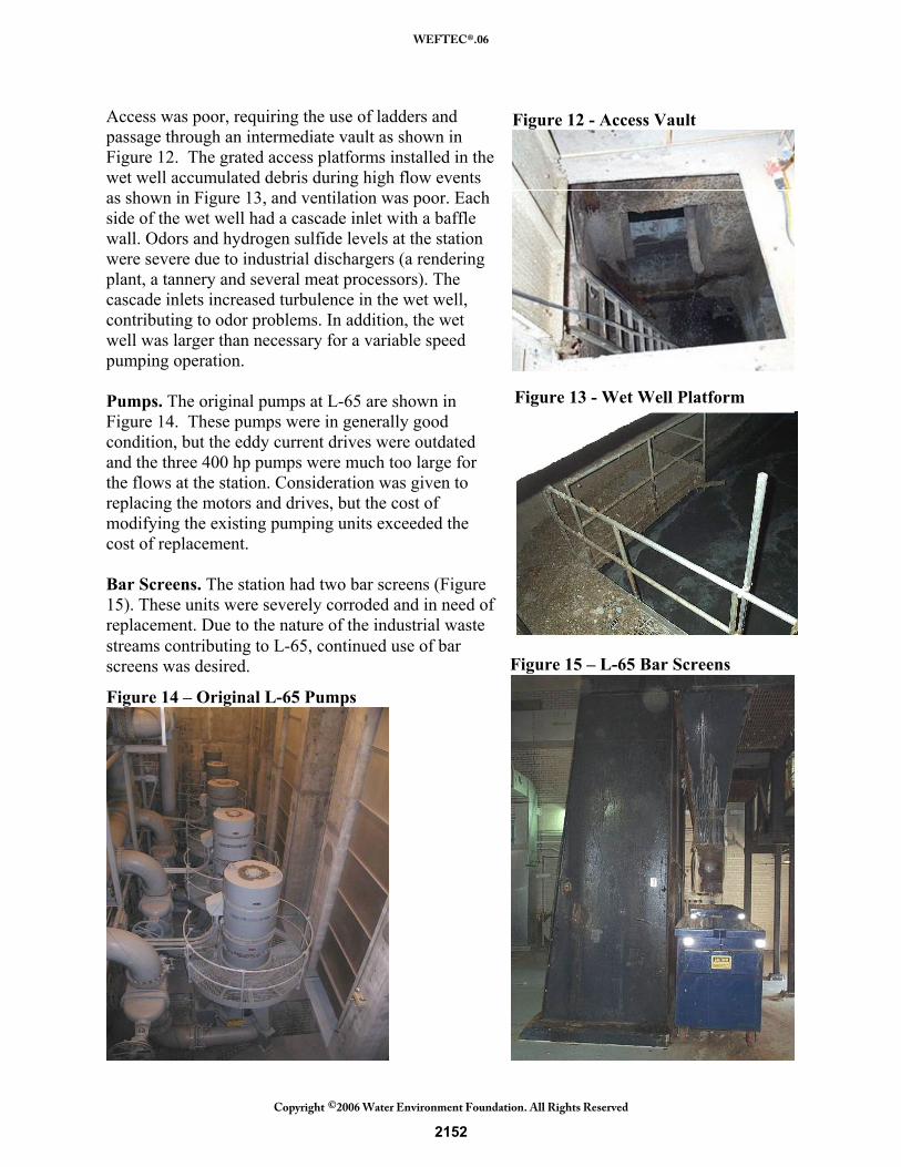
Bar Screens. The station had two bar screens (Figure 15). These units were severely corroded and in need of replacement. Due to the nature of the industrial waste streams contributing to L-65, continued use of bar screens was desired.
Figure 12 - Access Vault
Figure 13 - Wet Well Platform
Figure 15 – L-65 Bar Screens
Figure 14 – Original L-65 Pumps
2152
WEFTEC®.06
Copyright 2006 Water Environment Foundation. All Rights Reserved©

Ventilation/Odor Control. The make-up air units and foul air exhaust fans at L-65 were old and in need of replacement. In addition, the ventilation system needed to be upgraded to comply with the requirements of NFPA 820. Under NFPA 820, the wet side of the station (the bar screen area and wet well) need to be ventilated at 12 air changes per hour whenever the station is occupied or the supply air temperature exceeds 50° Fahrenheit. When the station is unoccupied or the supply air temperature is 50° Fahrenheit or less, the ventilation rate can be reduced to 6 air changes per hour.
Improvements at L-65 Improvements at L-65 focused on upgrading the entire lift station to contemporary design standards, within the limitations of the existing structure. Wet Well. The wet well at L-65 was reconfigured to a trench type design as shown in Figures 16, 17 and 18. An acceleration ramp was provided at the wet well inlet and the width reduced to that required for a trench type design. A new 72-inch influent pipe was provided, taking flow from the station’s bar screen effluent channel and routing it to the acceleration ramp at the south
end of the wet well. This pipe was configured to provide a straight approach of 10 pipe diameters, to ensure uniform approach conditions at the wet well inlet. Fillets and a splitter were provided along the length of the channel (Figures 16 and 17) to minimize the potential for vortexing and improve approach conditions at the pump inlet. These latter features are in conformance with revised geometry recommended for self cleaning wet wells in Pumping Station Design, 3rd Edition, and the updated version of ANSI/HI 9.8 to be published by the Hydraulic Institute in late 2006 or early 2007.
Figure 16 - Wet Well Longitudinal Section
2153
WEFTEC®.06
Copyright 2006 Water Environment Foundation. All Rights Reserved©

The modified station has provisions for two future pumps. The inlet bells for these pumps are already in place. The bell closest to the trench inlet limited the length of the acceleration ramp. The 45° slope was achieved, but the ogee curves at the top and bottom are tighter than desired. The bottom of the inlet bells are all located one-half of the bell diameter off the wet well floor. ANSI/HI 9.8 recommends that the bell on the pump at the downstream end of the trench be located one-fourth of the bell diameter off the wet well floor, to facilitate cleaning operations. The configuration of the existing structure prevented lowering of the suction piping for the end pump, and welding on extension on a ductile iron bell was not considered to be practical. Access to the wet well for inspection and maintenance was always a problem. A new door was cut in the wall between the lower bar screen room and the wet well (Figure 16). The concrete fill used to reconfigure the wet well to dimensions closer to those recommended in ANSI/HI 9.8 became the new access walkway for the wet well. The reduction in wet well cross section is apparent in Figures 17 and 18. The wet well originally had a width of 14 feet. The trench type wet well has a width of only 6.5 feet. In addition to the structural modifications to the wet well, ventilation was improved. The supply and exhaust air ducts are both evident in Figure 18. Supply air is powered in high, directed down towards the walkway where operations staff may be observing the wet well cleaning operation. Foul air is withdrawn low, close to the source of odors at the channel surface. As of May 19, 2006, the trench had been pumped down on three occasions to remove accumulated grease and debris. Operations staff report that prior to the first cleaning operation, a 6 inch thick layer of grease had accumulated on half of the wet well surface. This accumulated grease layer was successfully broken up and removed by pumping down the wet
Figure 18 – Wet Well Access and Ventilation
Figure 17 – L-65 Cross Section
2154
WEFTEC®.06
Copyright 2006 Water Environment Foundation. All Rights Reserved©

well, three times in immediate succession. The two subsequent cleaning operations were conducted before an extensive grease buildup could occur. The cleaning operation on May 19, 2006, was observed by members of the design team to assess the performance of the wet well. While the majority of accumulated debris was successfully removed from the trench, the formation of a hydraulic jump at the bottom of the acceleration ramp, progressing along the trench floor to the end pump was not achieved. The location of the end bell at one-half of a bell diameter off the trench floor instead of one-fourth of a bell diameter is suspected as the reason the hydraulic jump was not achieved. Pumps. Four 200 hp pumps with VFDs were provided in place of the five original pumps at L-65. The pumps were installed on concrete bases, similar to those used at the CIPS, as shown in Figure 19. While vibration was not a problem with the original pumps at L-65, a proper foundation is necessary to ensure smooth operation of the new pumps. A new motor level was provided, with the motors mounted independent of the pumps, as shown in Figure 20. Access to the motor level is from a landing on the pump room stairwell, allowing all motors to be inspected and maintained from a common operating level.
The pumping station had to remain in service throughout construction. A detailed sequencing plan was provided in the bid documents. A bulkhead was constructed in the wet well and the station was operated with two of the original 400 hp pumps while the three other pumps were removed and replaced. The work sequence required testing of three of the new pumps before the last two 400 hp pumps could be removed. On October 4, 2005, during the 30-day test period for these pumps, the Twin Cities metropolitan area had a major storm event with 5 to 9 inches of rain across the area in less than 24 hours. The three pumps functioned without incident during this event.
Figure 19 – L-65 Pumps
Figure 20 –L-65 Motors
2155
WEFTEC®.06
Copyright 2006 Water Environment Foundation. All Rights Reserved©

Bar Screens. New stainless steel articulated rake type bar screens were installed in place of the old chain drive screens, as shown in Figure 21. The new screens have a 1½ inch bar spacing, as their sole purpose is to protect the pumps from large debris that might enter the station during a storm event. A new roll-up door was cut into the building, to facilitate removal of the screenings dumpsters.
Ventilation/Odor Control. Improvements to air supply and exhaust in the wet well were shown in Figure 18. All air handling units and exhaust fans were replaced throughout the lift station and a bulk media biofilter was provided for odor control. Two foul air exhaust fans were provided, as shown in Figure 22, with the ventilation rate established in accordance with NFPA 820. Each foul air exhaust fan is rated at 9,000 cfm at a discharge pressure of 16 inches, to allow for increased pressure drop across the filter media over time. Initial discharge pressure is about 6 inches with the fans operating at reduced speed to provide the required air flow. As the media degrades and pressure increases, the fan speed will increase. One fan provides 6 air changes per hour when the space is unoccupied and the supply air temperature is 50° Fahrenheit or less. Both fans run when the building is occupied or the supply air temperature is above 50° Fahrenheit. A supply fan provides roughly 10 percent less air than the exhaust fan, to keep the wet side of the pumping station under negative pressure.
Figure 22 – Foul Air Exhaust Fan
Figure 21 - Bar Screens
2156
WEFTEC®.06
Copyright 2006 Water Environment Foundation. All Rights Reserved©

CONCLUSIONS In these two case studies, existing wastewater pumping stations were modified to more closely conform to ANSI/HI-9.8. The addition of acceleration ramps and stainless steel intake hoods and reconfiguration of the pump inlet piping at CIPS has improved wet well cleaning operations. Grit accumulation in the wet wells is no longer problems at CIPS. The L-65 lift station was successfully reconfigured to provide a trench type wet well. The width of the L-65 wet well is less than half of the original width and the wet well is now accessible, well ventilated and provided with sufficient lighting for routine maintenance activities. Pump down operations at L-65 have successfully removed grit, sludge and floatables from the wet well. The new pumps at both stations were installed on properly designed structural bases with independent support of the pumps and motors. This has eliminated the severe pump vibration problems that existed at CIPS before the improvements. Existing wastewater pumping stations can be modified to more closely comply with ANSI/HI 9.8, improving performance and simplifying operation and maintenance activities. ACKNOWLEDGMENTS We wish to acknowledge the operation and maintenance personnel at both the Monroe County Department of Environmental Services and Metropolitan Council Environmental Services for their input during the design and their patience during construction of the improvements to the two pumping stations. REFERENCES American National Standards Institute (1998) American National Standard for Pump Intake
Design ANSI/HI 9.8; Hydraulic Institute: Parsippany, N.J. Jones, Garr M.; Sanks, Robert L.; Tchobanoglous, George; Bosserman II, Bayard E. (2005)
Pumping Station Design, 3rd Edition; 2005; Butterworth-Heinemann: Woburn, Massachusetts.
National Fire Protection Association (1999) NFPA 820: Standard for Fire Protection in Wastewater Treatment and Collection Facilities; Quincy, Massachusetts.
2157
WEFTEC®.06
Copyright 2006 Water Environment Foundation. All Rights Reserved©