Pump Station Design YP Seminar FINAL-PRINT Station Design.pdfPump Station Design & Layout ......
28
David Bennett, P.E. Freese and Nichols Inc Freese and Nichols, Inc. November 16, 2010
Transcript of Pump Station Design YP Seminar FINAL-PRINT Station Design.pdfPump Station Design & Layout ......

David Bennett, P.E. Freese and Nichols IncFreese and Nichols, Inc.November 16, 2010
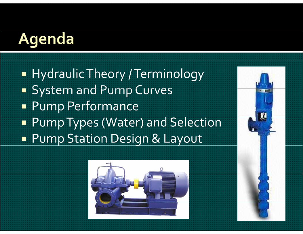
Hydraulic Theory / Terminology System and Pump Curves System and Pump Curves Pump Performance
d l Pump Types (Water) and Selection Pump Station Design & Layoutp g y
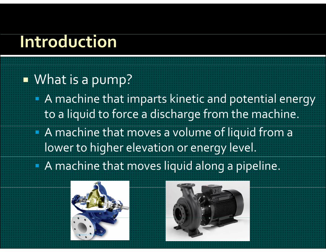
What is a pump?A hi th t i t ki ti d t ti l A machine that imparts kinetic and potential energy to a liquid to force a discharge from the machine. A machine that moves a volume of liquid from a lower to higher elevation or energy level. A machine that moves liquid along a pipeline.

General form:E E E E ET = Ep + Ev + Ez
Conservation of energy E1 = E2
Including losses & pumps:g p p Ep1 + Ev1 + Ez1 + EA = Ep2 + Ev2 + Ez2 + Ef
In terms of pressure head: In terms of pressure head: Hp1 + Hv1 + Hz1 + HA = Hp2 + Hv2 + Hz2 + Hf
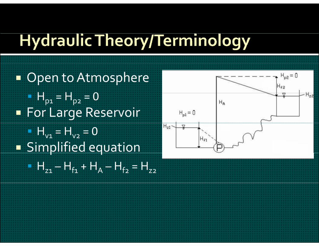
Open to AtmosphereH H 0 Hp1 = Hp2 = 0
For Large Reservoir Hv1 = Hv2 = 0
Simplified equationp q Hz1 – Hf1 + HA – Hf2 = Hz2
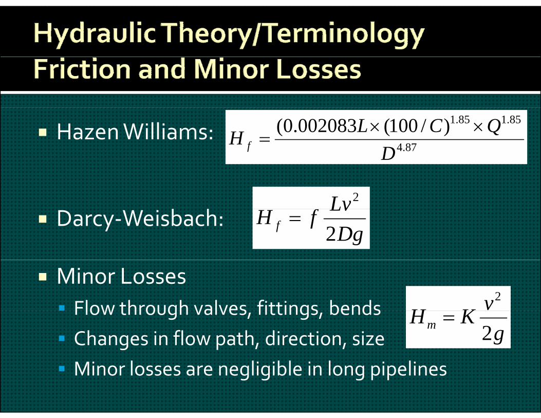
Hazen Williams:87.4
85.185.1)/100(002083.0(D
QCLH f
b h
D
Lv2
Darcy‐Weisbach:Dg
LvfH f 2
Minor Losses Flow through valves fittings bends vKH
2 Flow through valves, fittings, bends Changes in flow path, direction, size
l l bl l l
gKHm 2
Minor losses are negligible in long pipelines
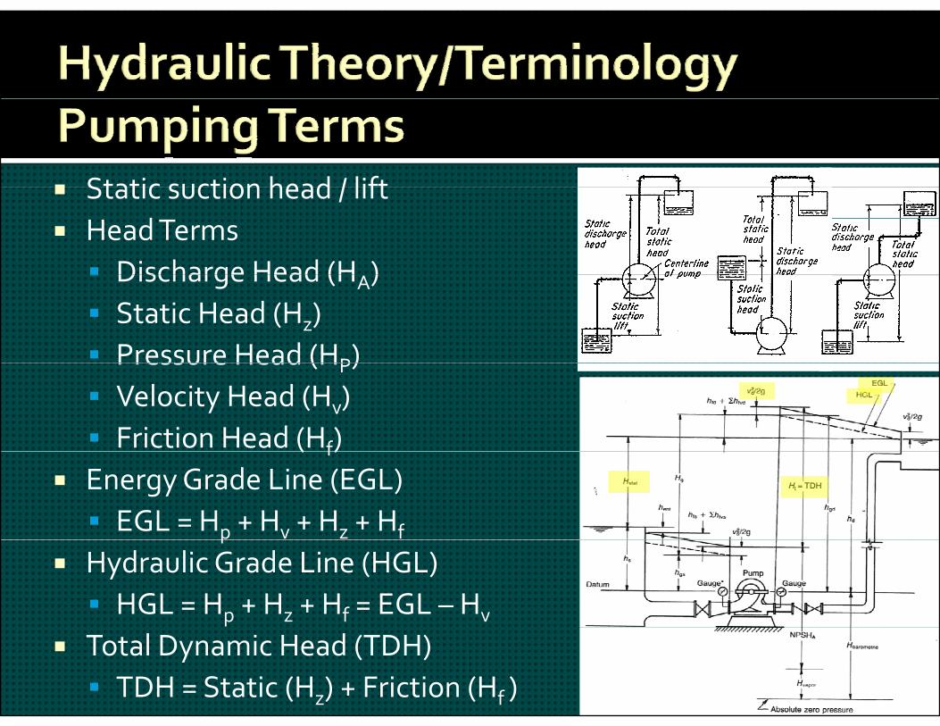
Static suction head / lift Static suction head / lift Head Terms Discharge Head (H ) Discharge Head (HA) Static Head (Hz) Pressure Head (HP)Pressure Head (HP) Velocity Head (Hv) Friction Head (Hf)( f)
Energy Grade Line (EGL) EGL = Hp + Hv + Hz + Hfp
Hydraulic Grade Line (HGL) HGL = Hp + Hz + Hf = EGL – Hv
Total Dynamic Head (TDH) TDH = Static (Hz) + Friction (Hf )
Determine static head Determine pipe size and length Determine pipe size and length Quantify friction and minor losses
l f Plot sum of: Static head Friction head from piping and minor losses
600
500
550
600
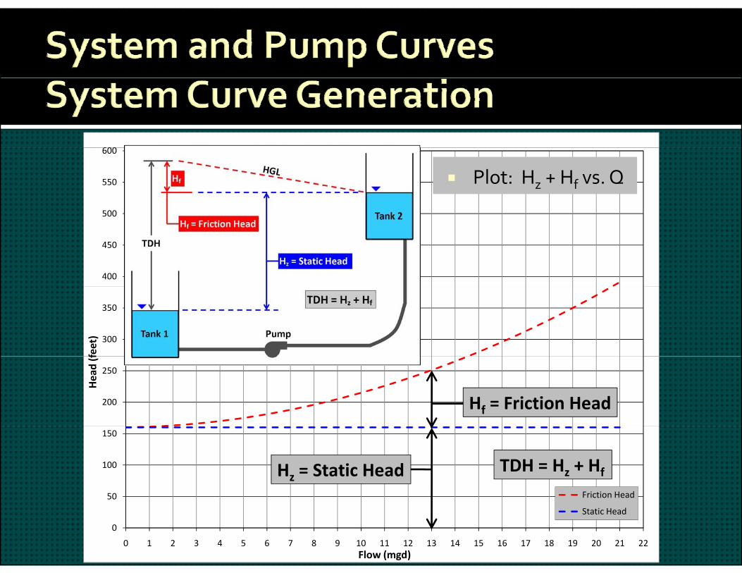
Plot: Hz + Hf vs. Q
400
450
300
350
feet)
200
250
Head (f
Hf = Friction Head
50
100
150
Friction Head
TDH = Hz + HfHz = Static Head
0
50
0 1 2 3 4 5 6 7 8 9 10 11 12 13 14 15 16 17 18 19 20 21 22Flow (mgd)
Friction Head
Static Head
600
450
500
550
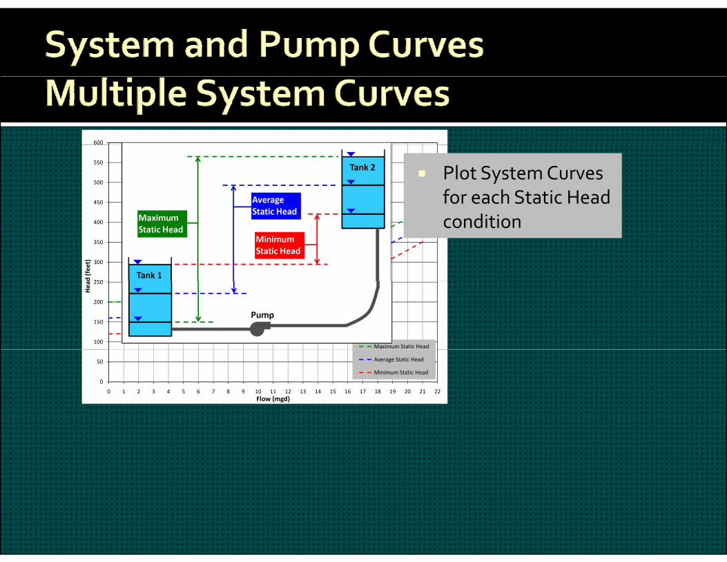
Plot System Curves for each Static Head
250
300
350
400
d (feet)
condition
100
150
200
250
Hea
Maximum Static Head
0
50
0 1 2 3 4 5 6 7 8 9 10 11 12 13 14 15 16 17 18 19 20 21 22Flow (mgd)
Average Static Head
Minimum Static Head
500
550
600
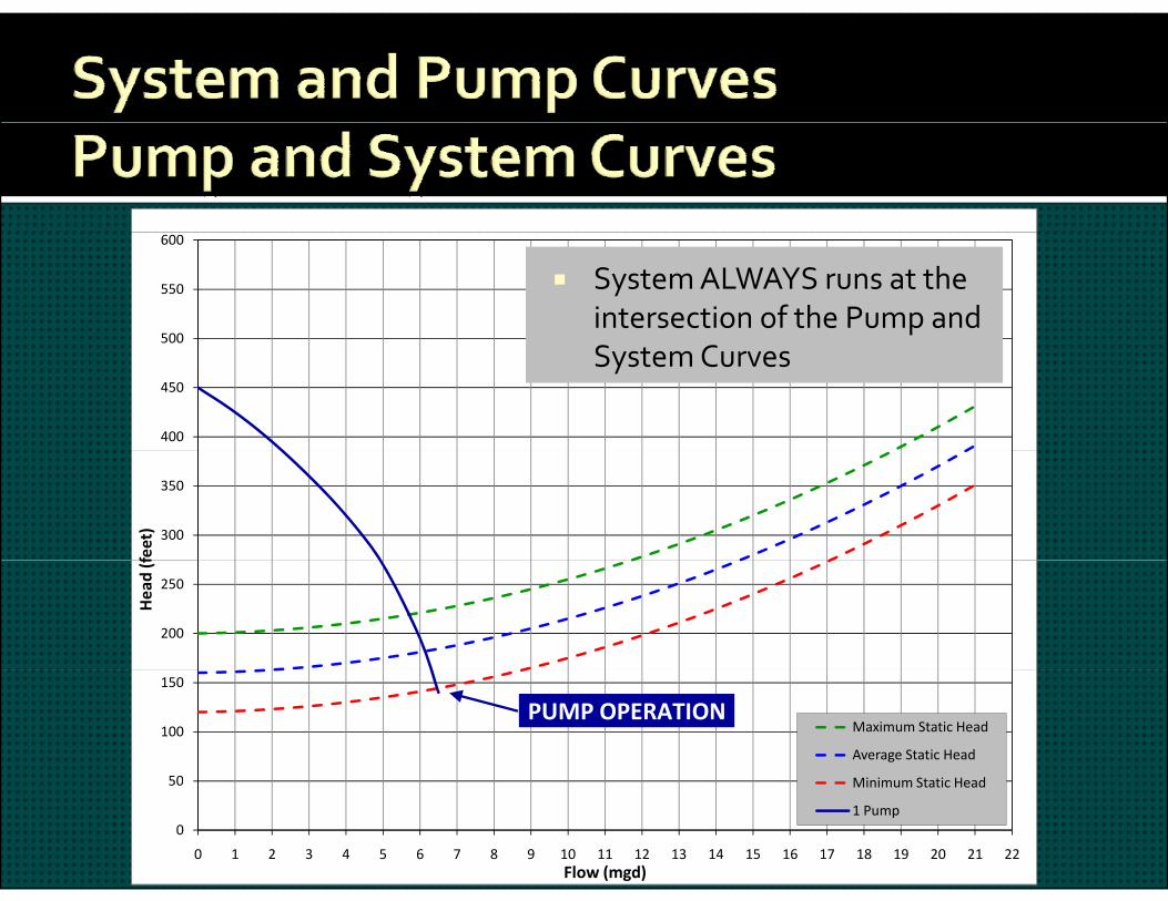
System ALWAYS runs at the intersection of the Pump and
400
450
500
System Curves
300
350
feet)
200
250
Head (f
50
100
150
Maximum Static Head
Average Static Head
Mi i St ti H d
PUMP OPERATION
0
50
0 1 2 3 4 5 6 7 8 9 10 11 12 13 14 15 16 17 18 19 20 21 22Flow (mgd)
Minimum Static Head
1 Pump

500
550
600
2 ‐ PUMPS
Parallel Pumps Add Q at given H
400
450
500IN PARALLEL
300
350
feet)
A
2A
3A
1 PUMP
200
250
Head (f B
2B 3B
C 2C 3C
1 ‐ PUMP
50
100
150
Maximum Static HeadAverage Static HeadMinimum Static Head1 Pump
C 2C 3C
3 ‐ PUMPSIN PARALLEL
0
50
0 1 2 3 4 5 6 7 8 9 10 11 12 13 14 15 16 17 18 19 20 21 22Flow (mgd)
1 Pump2 Pumps3 Pumps
500
550
600
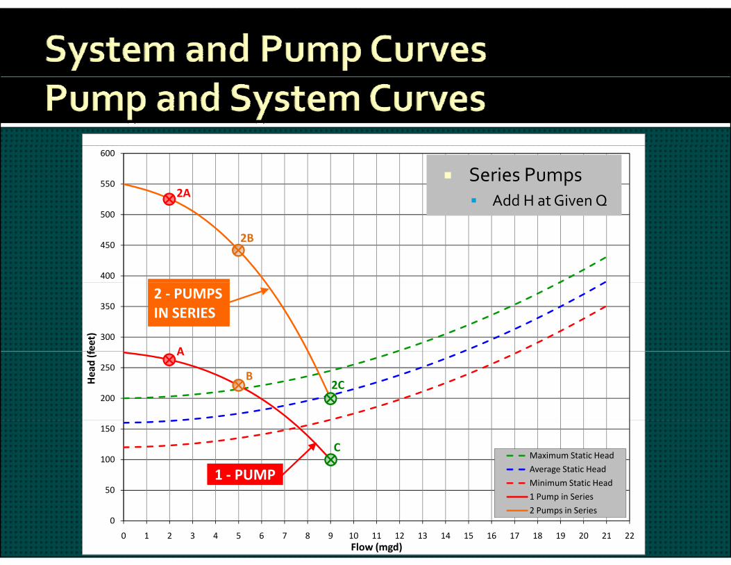
2A Series Pumps
Add H at Given Q
400
450
500
2B
300
350
feet)
A
2 ‐ PUMPSIN SERIES
200
250
Head (f A
B2C
50
100
150
Maximum Static Head
Average Static Head
Minimum Static Head
C
1 ‐ PUMP
0
50
0 1 2 3 4 5 6 7 8 9 10 11 12 13 14 15 16 17 18 19 20 21 22Flow (mgd)
1 Pump in Series
2 Pumps in Series
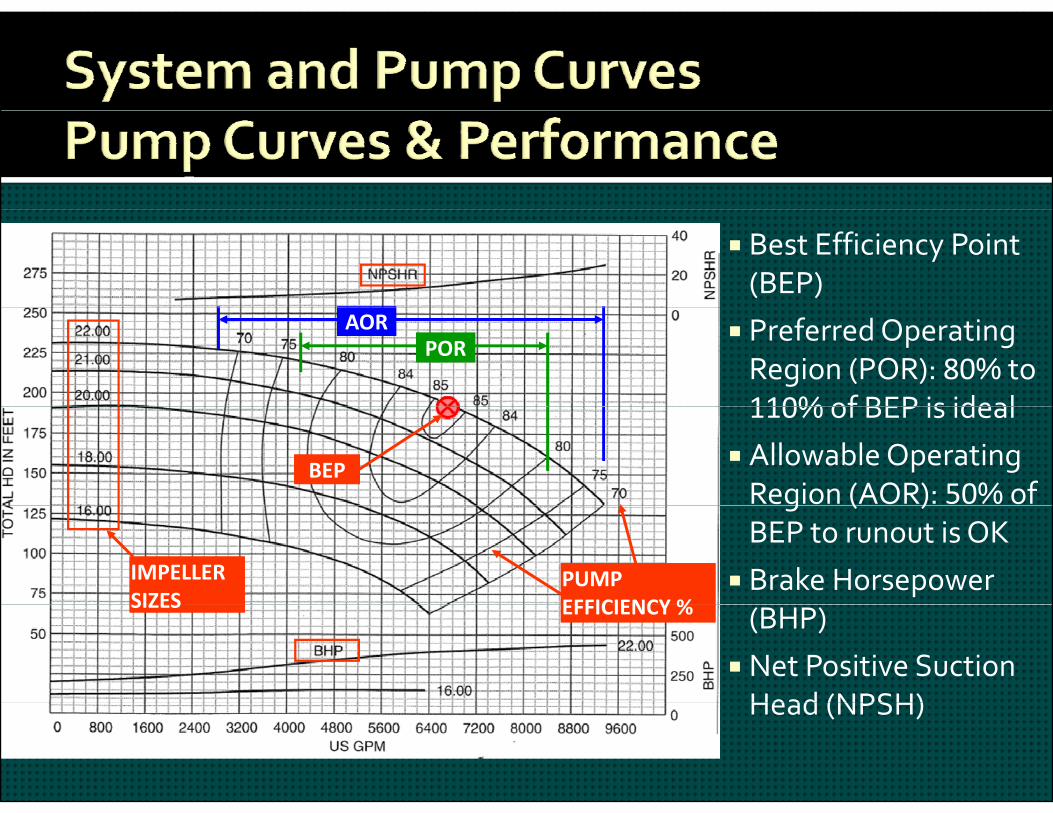
Best Efficiency Point (BEP)
Preferred Operating Region (POR): 80% to 110% of BEP is ideal
PORAOR
110% of BEP is ideal Allowable Operating Region (AOR): 50% of
BEPg ( )
BEP to runout is OK Brake Horsepower IMPELLER
SIZESPUMPEFFICIENCY % (BHP)
Net Positive Suction Head (NPSH)
SIZES EFFICIENCY %
Head (NPSH)
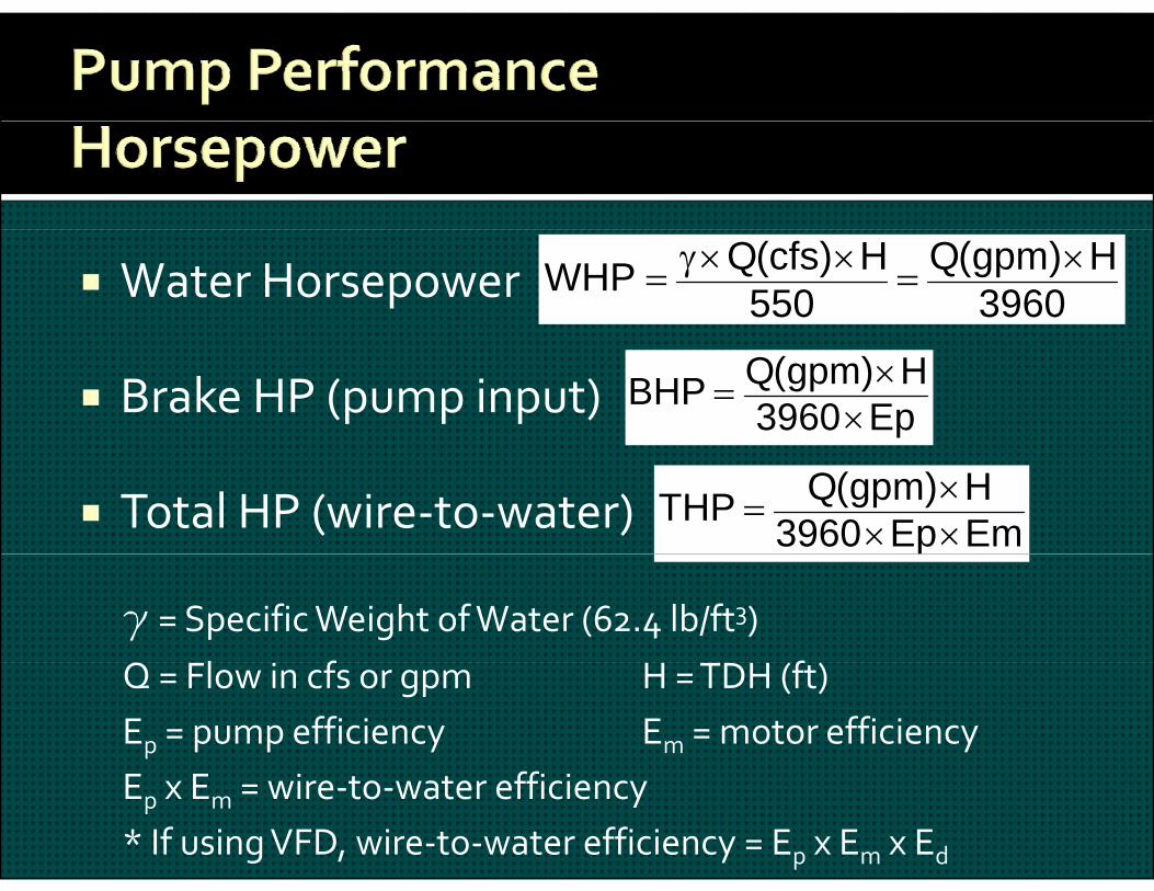
Water Horsepower 3960H)gpm(Q
550H)cfs(QWHP
Brake HP (pump input) Ep3960H)gpm(QBHP
Total HP (wire‐to‐water) EmEp3960H)gpm(QTHP
g = Specific Weight of Water (62.4 lb/ft3)l f fQ = Flow in cfs or gpm H = TDH (ft)
Ep = pump efficiency Em = motor efficiencyEp x Em = wire‐to‐water efficiency* If using VFD, wire‐to‐water efficiency = Ep x Em x Ed
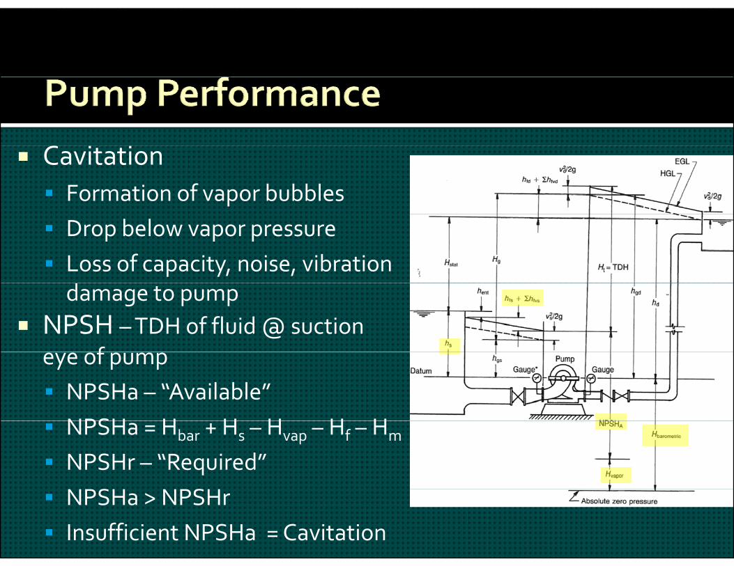
C Cavitation Formation of vapor bubbles Drop below vapor pressure Loss of capacity, noise, vibration damage to pump
NPSH –TDH of fluid @ suction f eye of pump
NPSHa – “Available”NPSH H H H H H NPSHa = Hbar + Hs – Hvap – Hf – Hm
NPSHr – “Required” NPSH NPSH NPSHa > NPSHr
Insufficient NPSHa = Cavitation
V i bl F D i (VFD)
500
550
600
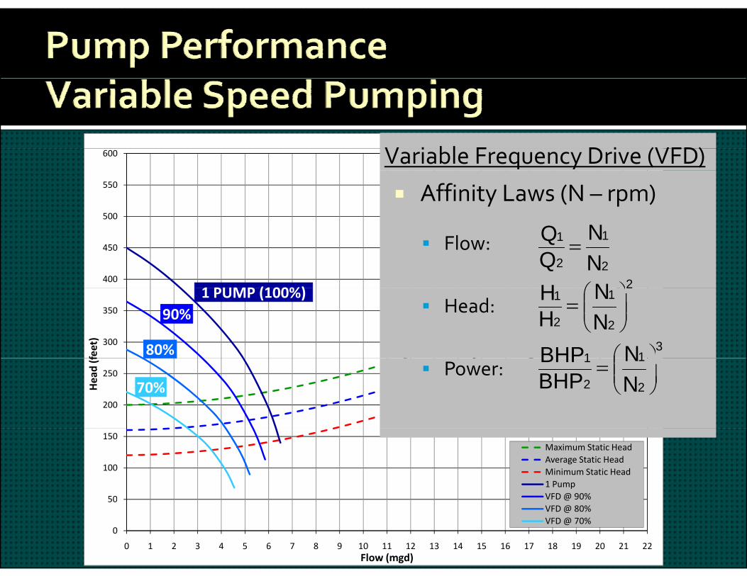
Affinity Laws (N – rpm)
Variable Frequency Drive (VFD)
400
450
500
1 PUMP (100%)
Flow:2
1
2
1
NN
2NH
300
350
feet)
1 PUMP (100%)90%
80%
Head:2
1
2
1
NN
HH
311 NBHP
200
250
Head (f
70% Power:
2
1
2
1
NN
BHPBHP
50
100
150Maximum Static HeadAverage Static HeadMinimum Static Head1 PumpVFD@ 90%
0
50
0 1 2 3 4 5 6 7 8 9 10 11 12 13 14 15 16 17 18 19 20 21 22Flow (mgd)
VFD @ 90%VFD @ 80%VFD @ 70%
V i bl F D i (VFD)
500
550
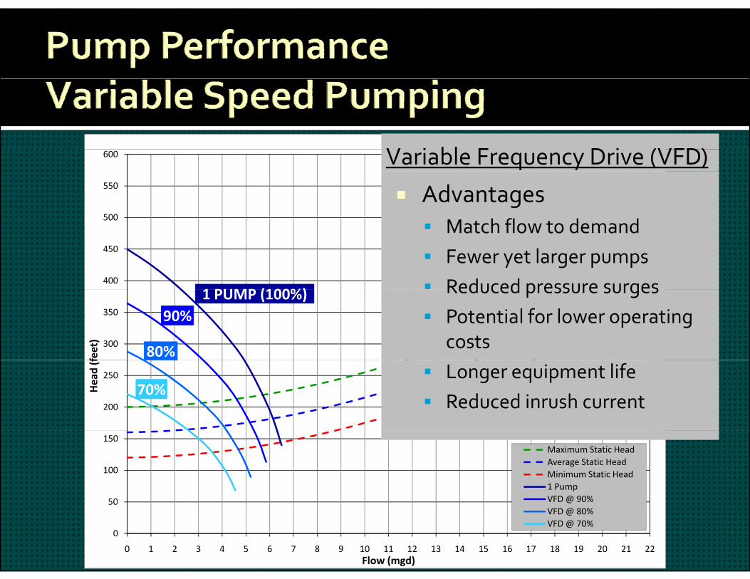
600 Variable Frequency Drive (VFD)
Advantagesh fl d d
400
450
500
1 PUMP (100%)
Match flow to demand Fewer yet larger pumps Reduced pressure surges
300
350
feet)
1 PUMP (100%)90%
80%
Reduced pressure surges Potential for lower operating
costs
200
250
Head (f
70% Longer equipment life Reduced inrush current
50
100
150Maximum Static HeadAverage Static HeadMinimum Static Head1 PumpVFD@ 90%
0
50
0 1 2 3 4 5 6 7 8 9 10 11 12 13 14 15 16 17 18 19 20 21 22Flow (mgd)
VFD @ 90%VFD @ 80%VFD @ 70%

V i bl F D i (VFD)
500
550
600
Disadvantages Higher capital / O&M costs
Variable Frequency Drive (VFD)
400
450
500
1 PUMP (100%)
Higher capital / O&M costs Increased equipment, larger
electrical room
300
350
feet)
1 PUMP (100%)90%
80%
Less electrical efficiency Higher potential for vibration Heat dissipation
200
250
Head (f
70%
Heat dissipation
50
100
150Maximum Static HeadAverage Static HeadMinimum Static Head1 PumpVFD@ 90%
0
50
0 1 2 3 4 5 6 7 8 9 10 11 12 13 14 15 16 17 18 19 20 21 22Flow (mgd)
VFD @ 90%VFD @ 80%VFD @ 70%
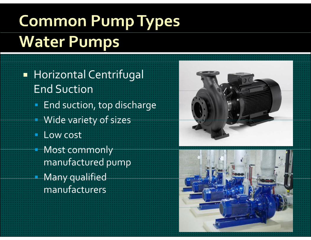
Horizontal Centrifugal End SuctionEnd Suction End suction, top discharge Wide variety of sizes Wide variety of sizes Low cost Most commonly Most commonly manufactured pump
Many qualified Many qualified manufacturers
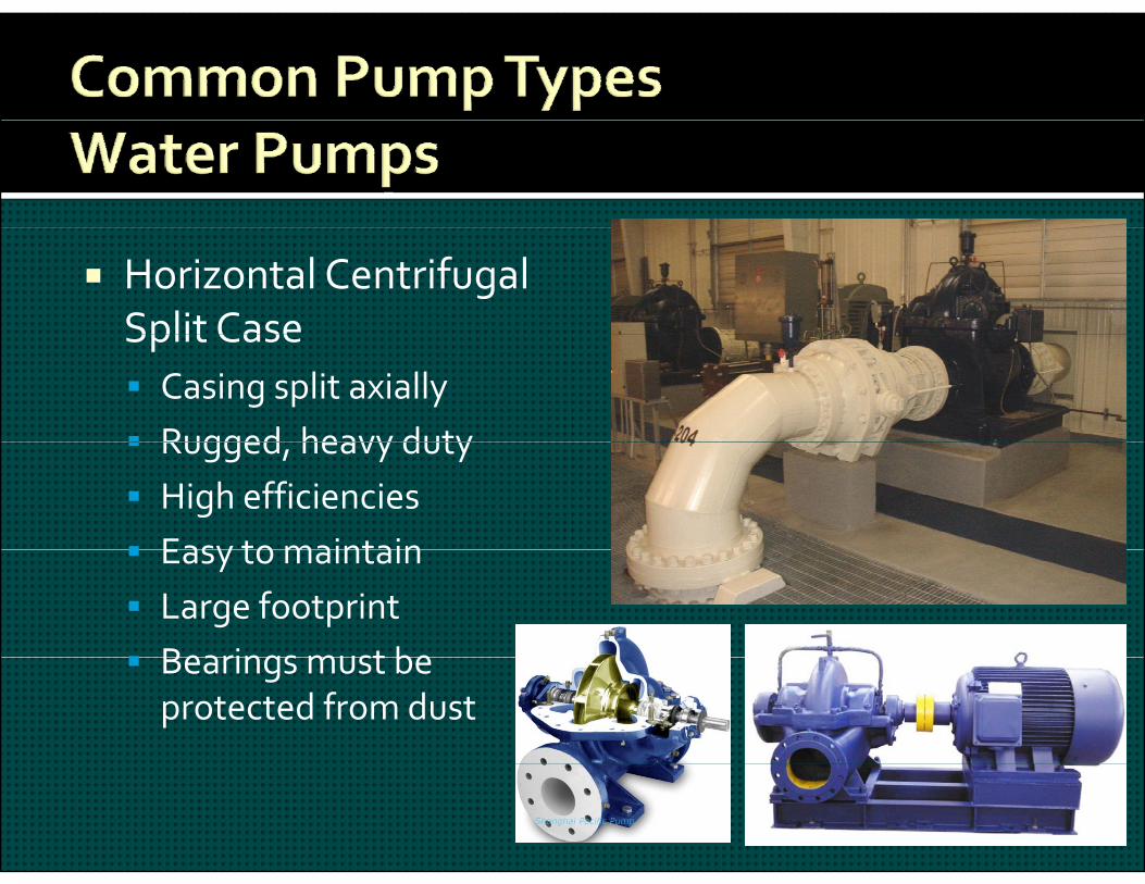
Horizontal Centrifugal Split CaseSplit Case Casing split axially Rugged heavy duty Rugged, heavy duty High efficiencies Easy to maintain Easy to maintain Large footprint Bearings must be Bearings must be protected from dust

Vertical Turbine –LineshaftLineshaft High head capability w/multiple stagesw/multiple stages
Tailor heads by adding bowls or stagesg
Installed in cans or sump Small footprintp Tight shaft tolerances

Vertical Turbine –SubmersibleSubmersible Submersible motor mounted at well bottom
No shafting or bearings above the bowl
blassembly Quiet operation Practical at long depths Practical at long depths Frequent maintenance requires pulling unitq p g
Long electric cables

Design and Peak Flows, PressuresO ti diti & t h d Operating conditions & system head curves
Select type, orientation & number of pumps Initial pump selection ‐ consult w/manufacturers Match pump and system curves Match pump and system curves Efficiencies, Horsepower, NPSH Performance curve analysis, operating points Capacity and/or Head increase optionsp y / p
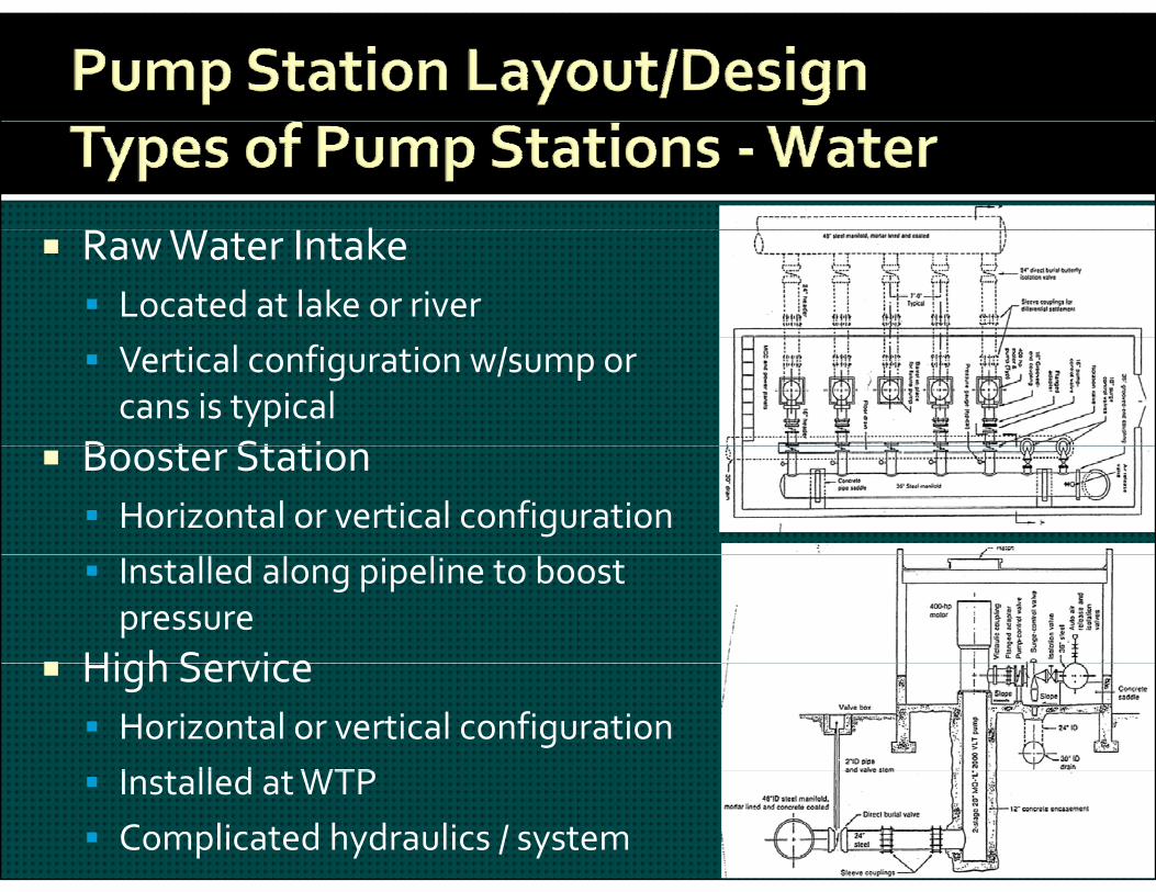
k Raw Water Intake Located at lake or river Vertical configuration w/sump or cans is typical
B t St ti Booster Station Horizontal or vertical configuration Installed along pipeline to boost pressure
High Service High Service Horizontal or vertical configurationI ll d WTP Installed at WTP
Complicated hydraulics / system
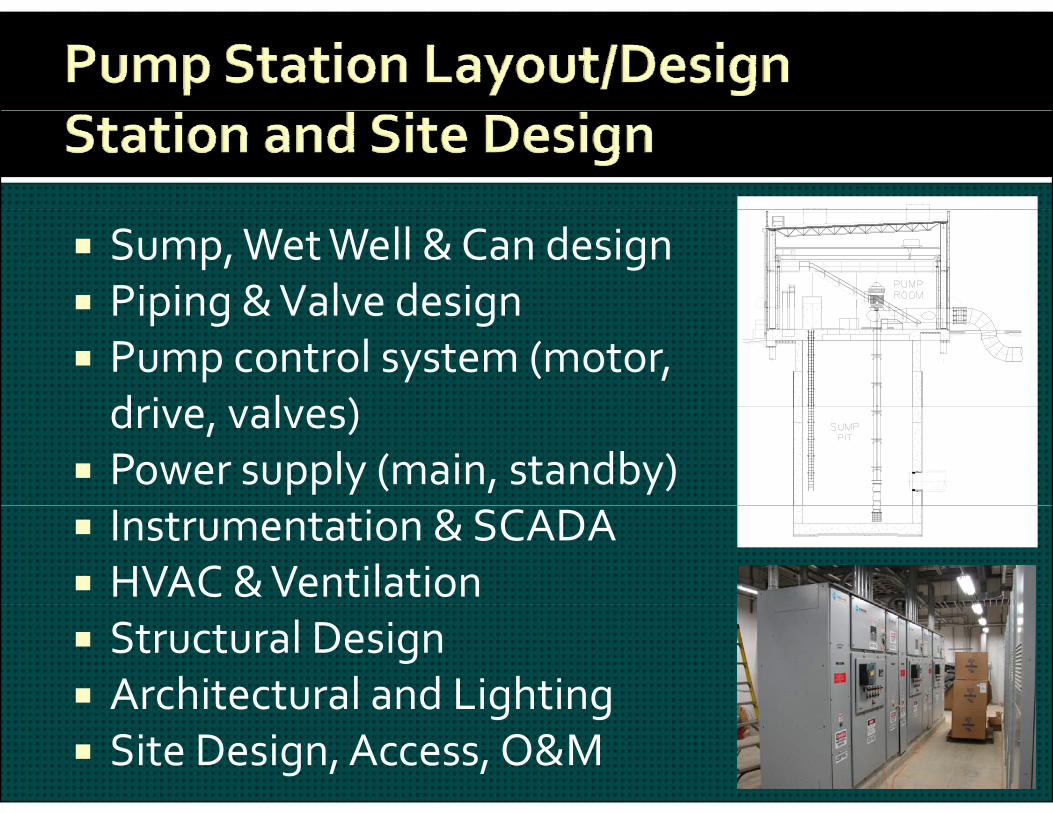
Sump, Wet Well & Can design Piping & Valve design Piping & Valve design Pump control system (motor, drive valves)drive, valves)
Power supply (main, standby) Instrumentation & SCADA HVAC & Ventilation Structural Design Architectural and LightingArchitectural and Lighting Site Design, Access, O&M
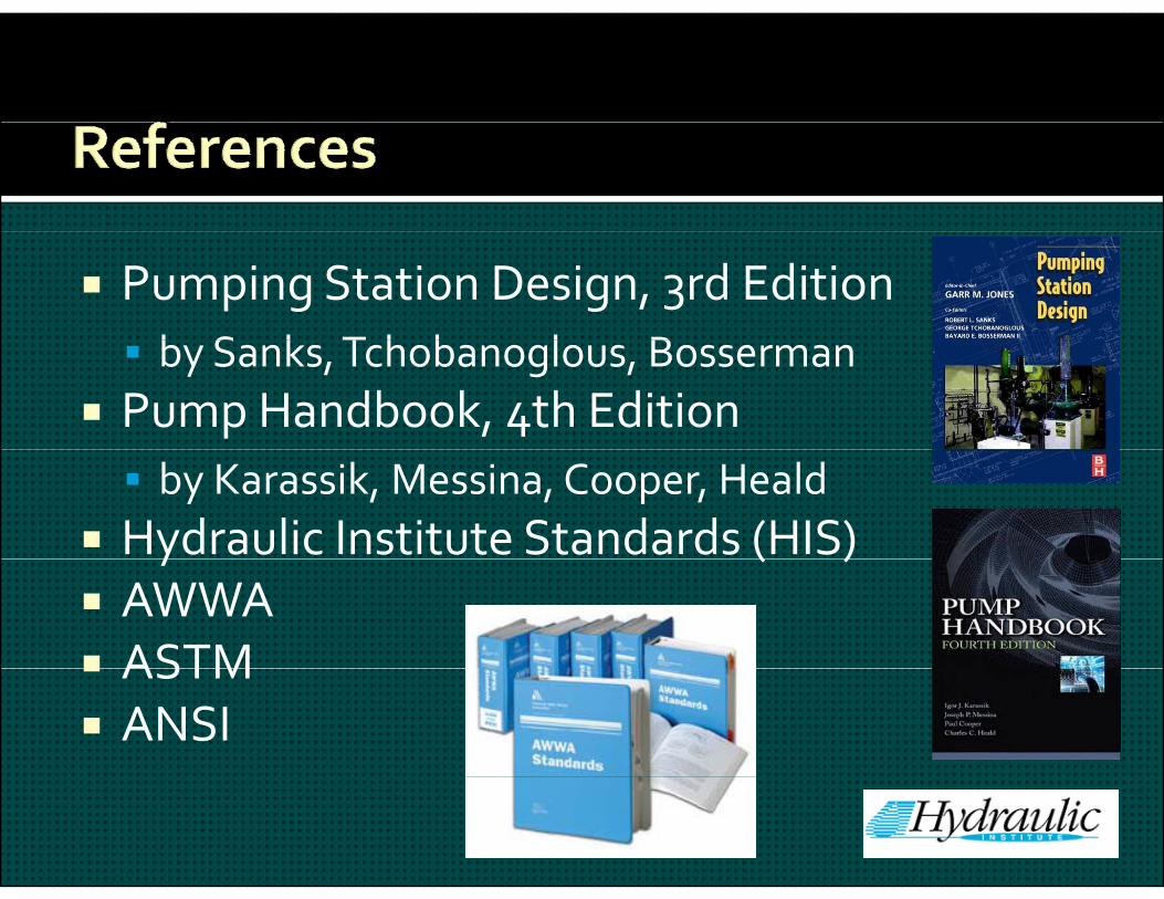
Pumping Station Design, 3rd Editionb S k T h b l B by Sanks, Tchobanoglous, Bosserman
Pump Handbook, 4th Edition by Karassik, Messina, Cooper, Heald
Hydraulic Institute Standards (HIS)y ( ) AWWA ASTM ASTM ANSI
Any Questions??
David Bennett, P.E.Freese and Nichols, Inc.Freese and Nichols, Inc.San Antonio Office4040 Broadway Street Suite 600San Antonio, Texas 78209p 210.298.3800 f [email protected]