Pump impeller failures — a compendium of case...
12
Pump impeller failures — a compendium of case studies A. van Bennekom a, *, F. Berndt b , M.N. Rassool a a School of Process and Materials Engineering, University of the Witwatersrand, Private Bag 3, P.O. WITS 2050, South Africa b Advanced Engineering and Testing Services, MATTEK, CSIR, Private Bag X28, Auckland Park 2006, South Africa Received 10 June 1999; accepted 26 October 1999 Abstract This paper presents a collection of pump impeller failures that have been encountered during the consulting activities at the University of the Witwatersrand and the Plant Infrastructure and Pipelines Centre at the Council for Scientific and Industrial Research. 7 2001 Published by Elsevier Science Ltd. Keywords: Casting defects; Cavitation failures; Coating failures; Impeller failures; Pump failures 1. Introduction The pumping of fluids within a plant and between plants is integral to the economic functioning of any chemical or petrochemical industry. It is thus of utmost importance that premature failure of these pieces of equipment be avoided. In addition to the pump problems that were experienced in the past, the woes of pump operators have been increased by some companies adopting a ‘zero-euent discharge policy’. Essentially this means that the euent that is produced by a particular plant has to be retained and recycled within the plant rather than discarding the euent into rivers or the environment. Unfortunately, the euent becomes more contaminated with each recycle and as such several problems can be encountered with pumps and associated piping systems since many of these systems were simply not designed to handle such concentrated or contaminated solutions. One of the best ways to avoid future failures is to examine the causes of failure in the past and to try and learn from past experience. Although pump failures may have many causes, this paper will only present case studies of impeller failures. Engineering Failure Analysis 8 (2001) 145–156 1350-6307/01/$ - see front matter 7 2001 Published by Elsevier Science Ltd. PII: S1350-6307(99)00044-8 www.elsevier.com/locate/engfailanal * Corresponding author. Tel.: +49(0) 217 808 2207; fax: +49(0) 271 808 2501. E-mail address: [email protected] (A. van Bennekom).
Transcript of Pump impeller failures — a compendium of case...
Pump impeller failures Ð a compendium of case studies
A. van Bennekoma,*, F. Berndtb, M.N. Rassoola
aSchool of Process and Materials Engineering, University of the Witwatersrand, Private Bag 3, P.O. WITS 2050, South AfricabAdvanced Engineering and Testing Services, MATTEK, CSIR, Private Bag X28, Auckland Park 2006, South Africa
Received 10 June 1999; accepted 26 October 1999
Abstract
This paper presents a collection of pump impeller failures that have been encountered during the consulting
activities at the University of the Witwatersrand and the Plant Infrastructure and Pipelines Centre at the Councilfor Scienti®c and Industrial Research. 7 2001 Published by Elsevier Science Ltd.
Keywords: Casting defects; Cavitation failures; Coating failures; Impeller failures; Pump failures
1. Introduction
The pumping of ¯uids within a plant and between plants is integral to the economic functioning ofany chemical or petrochemical industry. It is thus of utmost importance that premature failure of thesepieces of equipment be avoided.
In addition to the pump problems that were experienced in the past, the woes of pump operators havebeen increased by some companies adopting a `zero-e�uent discharge policy'. Essentially this meansthat the e�uent that is produced by a particular plant has to be retained and recycled within the plantrather than discarding the e�uent into rivers or the environment. Unfortunately, the e�uent becomesmore contaminated with each recycle and as such several problems can be encountered with pumps andassociated piping systems since many of these systems were simply not designed to handle suchconcentrated or contaminated solutions.
One of the best ways to avoid future failures is to examine the causes of failure in the past and to tryand learn from past experience. Although pump failures may have many causes, this paper will onlypresent case studies of impeller failures.
Engineering Failure Analysis 8 (2001) 145±156
1350-6307/01/$ - see front matter 7 2001 Published by Elsevier Science Ltd.
PII: S1350-6307(99 )00044-8
www.elsevier.com/locate/engfailanal
* Corresponding author. Tel.: +49(0) 217 808 2207; fax: +49(0) 271 808 2501.
E-mail address: [email protected] (A. van Bennekom).
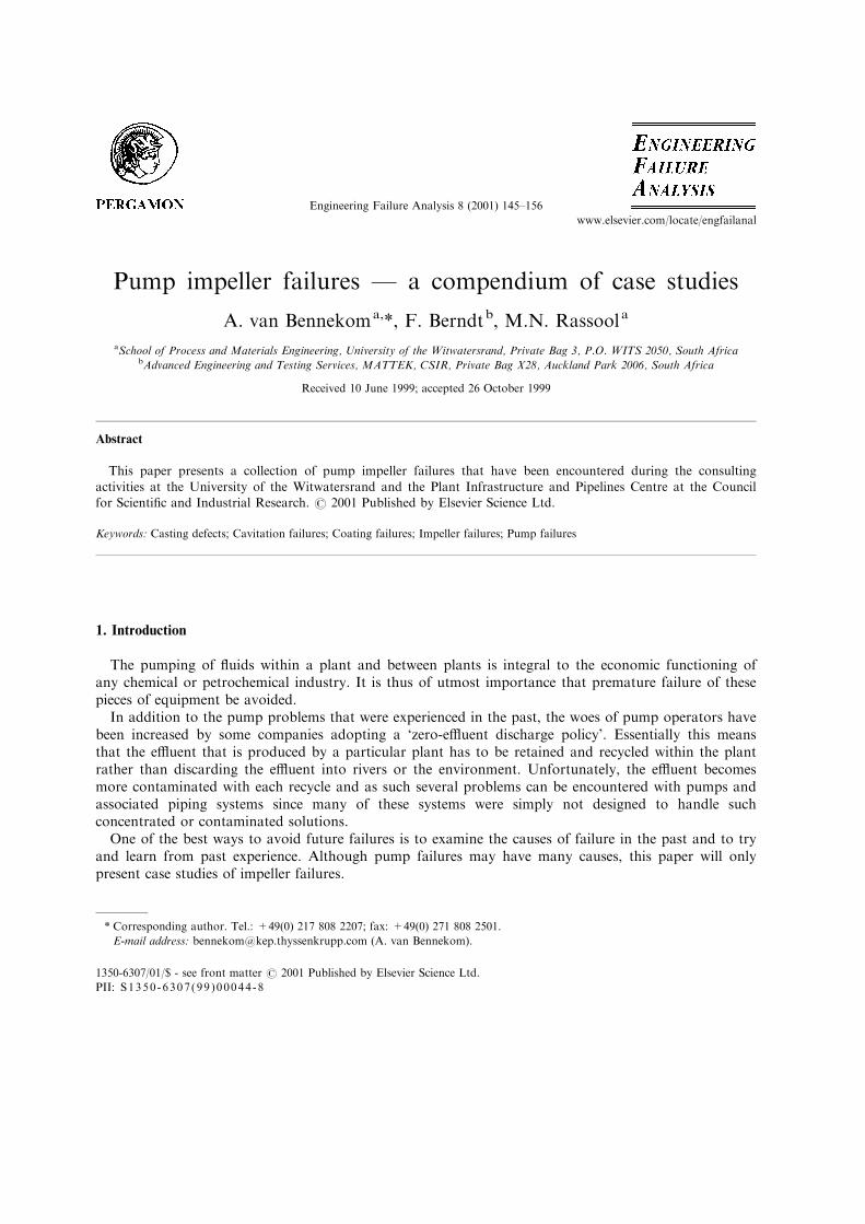
2. Fragmentation of a 316 impeller due to a casting defect
This CF-8M (cast equivalent of type 316 stainless steel) impeller, which was used to pump a nickelsulphate solution, fragmented after only a few hours in service. The failure of this impeller resulted in asigni®cant ®nancial loss due to subsequent damage and loss of production. On removal of the impeller,it was noted that some `pitting' and slight cracking was evident along the interface between the web and¯ange of the impeller (see Fig. 1). The plant personnel assumed the failure to be due to pitting corrosionin the nickel sulphate solution, but this was obviously not the case since the previous impeller, whichwas also made from CF-8M stainless steel, operated for several years without pitting being observed.Also, pitting would not be expected to occur this rapidly.
When a portion of the impeller, which was sectioned through the cracked and pitted region, wasprepared for metallographic examination by grinding and polishing a transverse section, extensiveporosity was observed. The extent and location of this porosity is evident in the photograph in Fig. 2.From the location and morphology of the porosity it is clear that this defect has been caused byshrinkage porosity during solidi®cation of the casting. Unfortunately, this defect is located in the mosthighly stressed portion of the impeller and it is thus not surprising that the impeller fragmented afteronly a short time in service.
When a metal solidi®es from the molten state, in a casting for instance, the volume of the metaldecreases and unless steps are taken to ensure that this shrinkage is compensated for by feeding thecasting with more liquid metal, shrinkage porosity will result. The resultant shrinkage porosity is usuallylocated at the last region to solidify and appears as an irregularly shaped cavity within the casting.
It can thus be seen that this failure was due to insu�cient feeding of the casting with molten metalduring the solidi®cation process. This failure could have been avoided if additional runners and risers
Fig. 1. `Pitting' and cracking at the junction between web and ¯ange of a cast 316 type stainless steel impeller.
A. van Bennekom et al. / Engineering Failure Analysis 8 (2001) 145±156146

had been used in the casting. It is also evident that a lack of quality control at the foundry that cast thisimpeller allowed the impeller to be dispatched and subsequently be installed in the pump where it failed.
A similar failure was observed in a bronze impeller which also failed after a relatively short time inservice. Examination of the fragments of this impeller showed that failure was due to the presence ofporosity in the casting. In fact, the porosity that was present on the fracture surface was so pronounced(see Fig. 3), that it was not necessary to perform a microstructural examination to con®rm the presenceof extensive shrinkage porosity.
3. Failure of a bronze impeller due to a casting defect
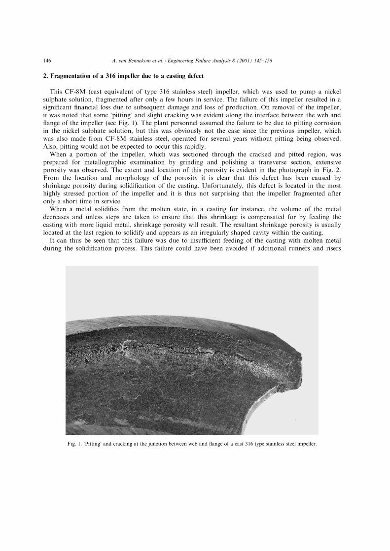
A bronze impeller was installed in a pump, but on start-up a signi®cant amount of vibration wasobserved followed by fragmentation of the impeller a few minutes later. When the fragments of theimpeller were examined, a blue oxide layer was observed on some of the fracture surfaces, showing thatthe impeller in question had failed due to the presence of a pre-existing crack.
The presence of this blue oxide layer on the fracture surface shows that the crack must have formedduring solidi®cation of the casting since a glossy blue oxide of this type only forms at high temperatures(see Fig. 4). The intriguing part about this failure is that the defect, which measures at least 6 cm inlength, was not detected by either the manufacturer or the technicians who installed the impeller. Thisfailure thus shows us that pump impellers should be visually examined for defects before they areinstalled into a pump.
From these two case studies it can be seen that metallurgical defects result in very rapid failure and
Fig. 2. Porosity on a cross section from the cracked region of Fig. 1.
A. van Bennekom et al. / Engineering Failure Analysis 8 (2001) 145±156 147

that the failures have very little to do with the operational conditions of the pump. Apart fromperforming a visual examination of the impeller before installation and ensuring that the supplieradheres to stringent quality control checks, there is very little that a pump operator can do to avoidfailure as a result of the presence of metallurgical defects.
4. Coating failure on an impeller wear ring
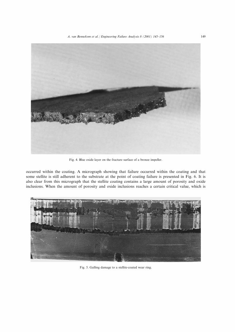
This case study is concerned with the failure of a stellite coating on an impeller wear ring. Theproblem manifested itself when severe vibration was detected on a pump in which a new stainless steelimpeller had just been installed. This vibration was found to become steadily worse until the pump wasstopped. The impeller was removed to determine the cause of the vibration. On removal of the impeller,it was noted that the wear ring had su�ered from extensive galling damage (see Fig. 5). Examination ofthe wear ring showed that it had been stellite-coated. The reason for coating the wear ring with a stellitecoating is to prevent or minimise the amount of galling damage that would usually occur between twostainless steel surfaces. As a general rule the coating that is used should be at least 50±60 Brinellhardness units higher than the hardness of the stainless steel.
After visual examination of the failed wear ring, it was thought that the stellite coating had spalled o�the stainless steel substrate due to inadequate surface preparation prior to thermal spraying of thestellite coating. When the wear ring was sectioned, and prepared for metallographic examination, it wasnoted that the interface between the coating and the stellite coating was intact and that failure had
Fig. 3. Porosity in a failed bronze impeller.
A. van Bennekom et al. / Engineering Failure Analysis 8 (2001) 145±156148
occurred within the coating. A micrograph showing that failure occurred within the coating and that
some stellite is still adherent to the substrate at the point of coating failure is presented in Fig. 6. It is
also clear from this micrograph that the stellite coating contains a large amount of porosity and oxide
inclusions. When the amount of porosity and oxide inclusions reaches a certain critical value, which is
Fig. 4. Blue oxide layer on the fracture surface of a bronze impeller.
Fig. 5. Galling damage to a stellite-coated wear ring.
A. van Bennekom et al. / Engineering Failure Analysis 8 (2001) 145±156 149

dependent on the operating stresses and type of coating, disbonding and spalling of the coating willoccur resulting in the damage observed in Fig. 5.
The speci®cation of a Ni based, self-¯uxing type of coating applied by powder ¯ame sprayingfollowed by fusing is correct, but it can be seen that some of the spraying parameters were notoptimised resulting in an inferior coating. Once again, there is nothing that the operator of the pumpcould have done to prevent failure of this type other than to insist that proper quality control measuresare implemented by the supplier of the pump components.
5. Cavitation case study
The following case study relates to the failure of a type CF-8M pump impeller by the mechanism ofcavitation (see Fig. 7). This impeller was used to pump an acidic (pH 2±3) nickel sulphate solution at a¯ow rate of between 1300 and 2000 l/min. The acid solution which was at a temperature of 20±308C,contained some precipitated crystals and had a general composition of: 6±10 g/l H2SO4, 500 g/l(NH4)2SO4, 0.1±0.2 g/l Ni, 0.1±0.2 g/l Co, 0.1±0.2 g/l (Fe+Mn), 50±70 ppm Clÿ and 2±5 g/l Na.
Examination of the impeller showed it to be extensively pitted, with the pitting damage being moresevere at some locations than at others, (see Fig. 8). The distribution and appearance of the pits showedthat failure was most likely due to cavitation.
Cavitation destroys the functional e�ciency of the component and leads to high running andmaintenance costs. It normally occurs at low pressure regions of rapidly vibrating liquid/metalinterfaces. Where the local pressure in a liquid is reduced below the vapour pressure of the liquidwithout temperature change, a condition may be reached where bubbles/cavities nucleate and growwithin the liquid body. The process of bubble formation is exceedingly rapid and is enhanced byturbulence (which can be caused by high ¯ow rates or surface irregularities of the component).
Damage is caused when the bubbles make contact with the surface and collapse due to a localised
Fig. 6. Failure of stellite coating in wear ring of Fig. 5 revealed by metallographic sectioning.
A. van Bennekom et al. / Engineering Failure Analysis 8 (2001) 145±156150

Fig. 7. Cavitation failure of cast 316 type stainless steel impeller.
Fig. 8. Close-up of impeller of Fig. 7.
A. van Bennekom et al. / Engineering Failure Analysis 8 (2001) 145±156 151

increase in the pressure. This is why cavitation damage is often observed at the high pressure side of apump (outlet) due to the bubbles collapsing under the in¯uence of the higher pressures in this region.Repeated implosions of these bubbles are su�cient to cavitate the surface, especially if corrosionproducts are present. These implosions are so severe, resulting in stresses of 60,000 lb/in2. or about 400MPa [1], that they can damage the passive ®lm of stainless steels and even remove some surfacematerial. It should also be noted that this stress is above the yield strengths of many materials and assuch some localised plastic deformation could also be expected. The exact mechanism by which collapseof the bubbles transmits the localised force to the surface is not fully understood, but it is thought toinvolve shock waves produced by the collapsing bubble, and the immediate development of a new cavity[2].
Due to the high rate of formation and decay of cavities, damage is rapid [3]. Cavitation damage canbe divided into four stages, namely:
Stage 1: bubbles form due to velocity or turbulence e�ects (pressure di�erences)Stage 2: bubbles make contact with the material surfaceStage 3: bubbles implode on the surface, setting up shock waves thereby damaging or removing somesurface materialStage 4: repetition of the above process.
Although the presence of a corrosive environment enhances cavitation damage, it is not essential tothe process. As far as predicting the resistance of a metal to cavitation damage, it appears as though thedegree of degradation is related to the pitting resistance rather than the general corrosion resistance ofthe material [4]. The presence of pits on the surface of the impeller also causes disruption of the lamellar¯ow conditions and therefore tends to create turbulent ¯ow which can lead to the creation of excesscavities/bubbles [4]. From this, it is evident that once cavitation has started, damage of the impeller willoccur at an ever-increasing rate.
When an impeller operates in a corrosive environment, damage as a result of cavitation may becon®rmed by the lack of corrosion products on the component's surface since these are removed by thecavitation process. Cavitation is also a�ected by the amount of entrained air and the presence of solidparticles that can act as nucleation sites for cavity formation. In this case no corrosion products wereobserved on the surface of the impeller, again con®rming that cavitation was the cause of failure.
Since the geometry of the pump and the properties of the liquid are relatively constant, the cavitieswill tend to form at preferred locations. With constant repetitive `implosions' a pit is formed locally anddegradation begins to accelerate. If the system has a stagnation period, a surface ®lm may form in thepit, but this is normally rapidly removed under dynamic ¯ow conditions and continued cavitation [5].
Cavitation can be controlled by the following methods:
. choice of materials
. hard-facing the surface of impellers to resist the e�ects of implosions
. using rubber or other linings to re¯ect shock waves without resulting in severe damage
. design to increase the pressure of the system or decrease the turbulence
. using inhibitors to increase vapour pressure of the liquid.
6. Microbial/bacterial induced corrosion (MIC/BIC)
When the media being pumped contains organic matter and nutrients, corrosion may be initiated oraccelerated by the action of micro-organisms which promote corrosion by various mechanisms. In most
A. van Bennekom et al. / Engineering Failure Analysis 8 (2001) 145±156152

cases it is the metabolic by-products such as organic and inorganic acids and hydrogen sulphide inaddition to the e�ects of di�erential aeration cells that are formed beneath the tubercles that causecorrosion of pump impellers and housings (including the protective coatings in some cases).
MIC is particularly a problem in nearly neutral water especially when the water contains sulphurcompounds and other organic nutrients.
Of the various organisms that promote corrosion, the best known are [6]:
Biological name Oxygen presence pH range Temperature rangeDesulfovibrio desulfuricans (anaerobic) pH 4±8 10±408CThiobacillus thiooxidans (aerobic) pH 0.5±8 10±408C
As can be seen from the conditions required for proliferation of these micro-organisms, colonisationof the metal surface can occur under both aerobic and anaerobic conditions. Corrosion by the anaerobicsulphate reducing bacteria, Desulfovibrio desulfuricans, can even proceed under aerobic conditions iftubercles are present. This is because the tubercles create a protective anaerobic environment in whichthe anaerobic bacteria can thrive.
Although some strains of corrosion-promoting bacteria can survive outside the ranges presentedabove, these are less common and are thus of less importance.
Since very low ¯ow or stagnant conditions are required for colonisation of the bacteria,microbiologically in¯uenced corrosion is seldom encountered in pump components. A recent failure hashowever been encountered where reduction in the demand for water has resulted in one of the pumps inthe pump station being used for standby and during peak demand periods. In the interim, however, thepump is idle and contains stagnant water for a period up to several weeks. During this period su�cienttime is available for microbial colonisation and corrosion to occur. In addition to pitting caused by thebacteria, examination of the pump impeller revealed some signs of early cavitation damage which wassuspected to occur as a result of the tubercles, that form from bacterial colonisation, interfering with the¯ow characteristics and causing turbulent ¯ow.
In situations like this, use of the pumps should be alternated to ensure that the pumps are notallowed to remain stationary for more than 24 h. If this is done, then the formation of bacteria will belimited and thus microbially in¯uenced corrosion of the pump components should also be limited.
7. General corrosion
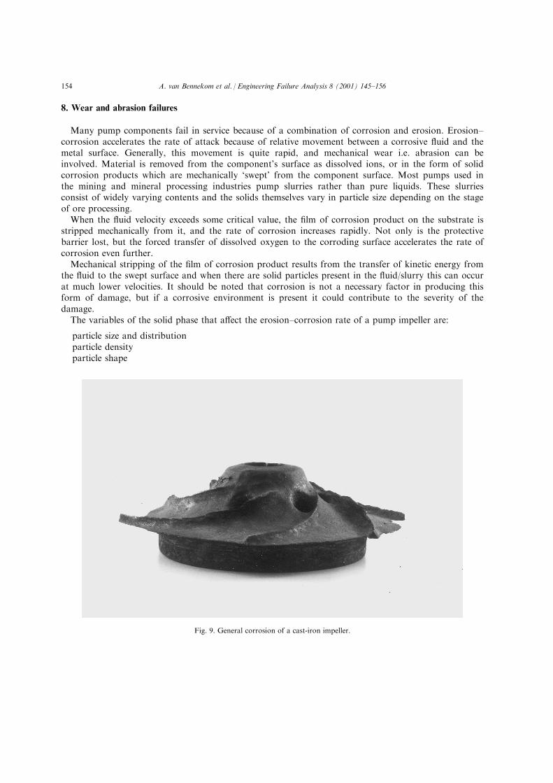
General corrosion of pump components, especially impellers, usually occurs when the incorrectmaterials have been chosen for the speci®c application or when the service conditions in which the pumpoperates have changed. As the name would imply, general corrosion is the name given to the uniformremoval of metal from the surface of a metallic component over a period of time. Since the corrosion isuniform, damage of this type manifests itself over a period of time and is usually detected by a gradualdecline in pump e�ciency. A photograph of a cast-iron pump impeller which has been removed fromservice due to general corrosion is presented in Fig. 9. It is clear from this photograph that the impellerhas become signi®cantly thinned due to general corrosion and that the pump e�ciency would also havebeen unacceptable. This impeller was used to pump relatively low pH waters. Had a stainless steel orbronze impeller been used, no corrosion problems would have been experienced. It should also be notedthat recent advances in coating technology have resulted in the formulation of several coatings that canbe used to protect pump components by forming a physical barrier between the metal components andthe media being pumped.
A. van Bennekom et al. / Engineering Failure Analysis 8 (2001) 145±156 153
8. Wear and abrasion failures
Many pump components fail in service because of a combination of corrosion and erosion. Erosion±corrosion accelerates the rate of attack because of relative movement between a corrosive ¯uid and themetal surface. Generally, this movement is quite rapid, and mechanical wear i.e. abrasion can beinvolved. Material is removed from the component's surface as dissolved ions, or in the form of solidcorrosion products which are mechanically `swept' from the component surface. Most pumps used inthe mining and mineral processing industries pump slurries rather than pure liquids. These slurriesconsist of widely varying contents and the solids themselves vary in particle size depending on the stageof ore processing.
When the ¯uid velocity exceeds some critical value, the ®lm of corrosion product on the substrate isstripped mechanically from it, and the rate of corrosion increases rapidly. Not only is the protectivebarrier lost, but the forced transfer of dissolved oxygen to the corroding surface accelerates the rate ofcorrosion even further.
Mechanical stripping of the ®lm of corrosion product results from the transfer of kinetic energy fromthe ¯uid to the swept surface and when there are solid particles present in the ¯uid/slurry this can occurat much lower velocities. It should be noted that corrosion is not a necessary factor in producing thisform of damage, but if a corrosive environment is present it could contribute to the severity of thedamage.
The variables of the solid phase that a�ect the erosion±corrosion rate of a pump impeller are:
particle size and distributionparticle densityparticle shape
Fig. 9. General corrosion of a cast-iron impeller.
A. van Bennekom et al. / Engineering Failure Analysis 8 (2001) 145±156154

particle compositionconcentration of solid in the slurry.
Variation in the rate of erosion with the concentration of solids in a slurry appears to follow ade®nite pattern. This is a linear increase in the rate of material damage with increasing concentration ofsolids up to a certain level, followed by a much slower rate of increase at higher concentration.Erosion±corrosion is characterised by the presence of grooves, as illustrated in Fig. 10, and holes on thesurface of the metal, which usually exhibit a directional pattern.
Passive alloys, such as stainless steels, depend on the development of a tightly adhering surface oxide®lm for resistance to corrosion. In quiescent acids and acidic waters, these alloys may be resistant toattack. In ¯owing acids, however, operation at velocities above a certain critical level may destroy thepassive layer, causing the alloy to become active and corrode rapidly. This velocity is referred to as the`breakdown velocity'. Since the rate of corrosion in the active state can be orders of magnitude higherthan in the passive state, the e�ect of erosion±corrosion can be very marked. Slurries containingparticles denser than water will give rise to a lower breakdown velocity.
References
[1] Fontana MG. Corrosion engineering. 3rd ed. New York: McGraw-Hill, 1987 International Editions.
[2] American Society for Metals. Failure analysis and prevention. In: Metals handbook, vol. 11. 9th ed. Metals Park, OH:
American Society for Metals, 1986.
[3] Colangelo VJ, Heiser FA. Analysis of metallurgical failures. New York: Wiley, 1974.
Fig. 10. Erosion±corrosion grooves and depressions on an impeller surface.
A. van Bennekom et al. / Engineering Failure Analysis 8 (2001) 145±156 155

[4] Godfrey DJ. In: Schreir LL, editor. Corrosion, vol. 1. New York: Wiley, 1963. p. 8.
[5] Wulpi DJ. Understanding how components fail. Metals Park, OH: AIM, 1985.
[6] Jones DA. Principles and prevention of corrosion. Maxwell MacMillan, 1992 International Editions.
A. van Bennekom et al. / Engineering Failure Analysis 8 (2001) 145±156156