
Design and Prototyping of Centrifugal Pump Impeller to be...
87
Design and Prototyping of Centrifugal Pump Impeller to be used as Water Injection Pump for Hydrocarbon Artificial Lift. by Mohd Radzi Bin Mohd Anua Dissertation submitted in partial fulfillment of the requirements for the Bachelor of Engineering (Hons) (Mechanical Engineering) JANUARY 2008 Universiti Teknologi PETRONAS Bandar Seri Iskandar 31750 Tronoh Perak Darul Ridzuan
Transcript of Design and Prototyping of Centrifugal Pump Impeller to be...

Design and Prototyping of Centrifugal Pump Impeller to be used as Water Injection
Pump for Hydrocarbon Artificial Lift.
by
Mohd Radzi Bin Mohd Anua
Dissertation submitted in partial fulfillment of
the requirements for the
Bachelor of Engineering (Hons)
(Mechanical Engineering)
JANUARY 2008
Universiti Teknologi PETRONAS
Bandar Seri Iskandar
31750 Tronoh
Perak Darul Ridzuan

I
CERTIFICATION OF APPROVAL
Design and Prototyping of Centrifugal Pump Impeller to be used as Water Injection
Pump for Hydrocarbon Artificial Lift
by
Mohd Radzi Bin Mohd Anua
A project dissertation submitted to the
Mechanical Engineering Programme
Universiti Teknologi PETRONAS
in partial fulfilment of the requirement for the
BACHELOR OF ENGINEERING (Hons)
(MECHANICAL ENGINEERING)
Approved by,
_____________________
(Dr. Ahmad Majdi Abd. Rani)
UNIVERSITI TEKNOLOGI PETRONAS
TRONOH, PERAK
January 2006

II
CERTIFICATION OF ORIGINALITY
This is to certify that I am responsible for the work submitted in this project, that the original
work is my own except as specified in the references and acknowledgements, and that the
original work contained herein have not been undertaken or done by unspecified sources or
persons.
___________________________
MOHD RADZI BIN MOHD ANUA

III
ABSTRACT
Execution of maintenance activities for mechanical equipment is essential in order to
preserve and enhance plant and equipment reliability. It is common especially during
corrective and preventive maintenance activities to replace defective or to-be defective
components. Typically the replacement components are procured through the original
equipment manufacturer (OEM). However, due to the long lead-time delivery imposed by the
OEM, an alternative means of procuring spares with shorter lead-time delivery should be
established, in order to reduce the downtime of critical equipment should extreme cases such
as repetitive failure of certain components occur. This project was carried out with such
objective by studying the feasibility of locally designing and manufacturing mechanical
components to reduce shipping time, and adopting rapid prototyping technology into spare
parts manufacturing, to reduce manufacturing time. A centrifugal pump impeller was chosen
to be designed and manufactured. The data of operating requirements of the particular pump
was acquired from an existing water injection module in an actual oil field. The project
started with impeller numerical design, establishing the geometry in numerical terms. The
methodology was then preceded by impeller modeling, resulting in a virtual three
dimensional representation of the designed impeller. The virtual model was then rapidly
transformed into a solid wax prototype using rapid prototyping technology. The wax
prototype was then directly used as a pattern for investment casting process, resulting in solid
metallic model of the impeller. The whole processes duration and costs was recorded. A
costs-time benefit analysis was carried out in the latter part of the project, to study the
feasibility of the approaches adopted in this project, and to compare the its practicality to that
of the conventional spare parts procurement through the OEM, in terms of costs and led-time
delivery. It was concluded from the analysis, that this project dramatically reduced the lead-
time delivery, and radically reduced the product’s costs. In conclusion, the approaches
adopted in this project (locally designing, locally manufacturing, and introducing rapid
prototyping into spare parts manufacturing) are verified to be very feasible and favorable as
far as the lead-time delivery and costs are concerned. This project also adds to plant and
equipment reliability by reducing equipment downtime thus enabling continuation of
production and plant operation.

IV
ACKNOWLEDGEMENTS
I would like to first and foremost extend my greatest gratitude to Allah S.W.T. for I believe,
exactly nothing would have happened without His consent and blessings.
I would also be fond to acknowledge the contribution given by the project’s supervisor, Dr.
Ahmad Majdi Abd. Rani, for guiding me towards the right path in coming up with a solid
project with fine fulfilled objectives and equipping myself with good technical report writing
skills.
I would also like to express my appreciation to those directly involved in the manufacturing
stage of this project, Mr. Khurram, Mr. Zamil, and Mr, Jani from UTP, a huge thanks from
me to all of you.
It would be appalling not to address the persons that have personally assisted and facilitated
me in some way during the endeavor of this project. Special thanks go to my former
internship supervisors, Mr. Nizam Nadzimuddin and Mr. Sura Venkata Srikanth , Mr. Hazri
and Mr. Lai from Primametals Sdn. Bhd., and Mr. Kevin and Mr. Michael Tan from
Flowserve Corporation.
And last but not least to my special friend, friends, and colleagues who have always been
looking over my shoulder throughout the completion of this project. With cherry on top, I
would like to once again convey my numerous thanks and gratitude on those who are directly
or indirectly involved in assisting me during this project. Thank You.
This project is dedicated to my family, who has always been there for me.
Mohd Radzi Mohd Anua

V
TABLE OF CONTENTS
CERTIFICATION OF APPROVAL . . . . . . I
CERTIFICATION OF ORIGINALITY . . . . . . II
ABSTRACT . . . . . . . . . . III
ACKNOWLEDGEMENTS . . . . . . . IV
LIST OF FIGURES . . . . . . . . . VIII
LIST OF TABLES . . . . . . . . . X
ABBREVIATIONS AND NOMENCLATURES . . . . . XI
CHAPTER 1 INTRODUCTION . . . . . . . 1
1.1 Problem Statement . . . . . . 2
1.1.1 Long-lead Replacement Spares . . . . 2
1.1.2 Possibility of Repetitive Failure . . . . 3
1.2 Objective and Scope of Study . . . . 4
CHAPTER 2 LITERATURE REVIEW . . . . . . 7
2.1 Water Injection Module in Petroleum Production Facilities 7
2.2 Centrifugal Pumps Design and Application . . . 7
2.3 Centrifugal Pump Impeller . . . . . 7
2.3.1 Impeller Key . . . . . . . 9
2.3.2 Impeller Wear Rings . . . . . . 10
2.3.3 Shaft Sleeves . . . . . . . 10
2.4 Pump Characteristics Curve . . . . . 11
2.5 Pump Specific Speed . . . . . . 12
2.6 Pump Shut-Off Head . . . . . . 12
2.7 Shaft Sizing . . . . . . . 13
2.8 Net Positive Suction Head Required . . . . 13
2.9 Pumped Fluid . . . . . . . 13
2.10 Mechanical Spare Parts Classification . . . 14
2.11 The Design Process . . . . . . 15
2.12 Rapid Prototyping . . . . . . 16
2.13 Casting Processes . . . . . . 18
2.13.1 Investment Casting . . . . . . 18
VI
2.13.1.1 Investment Casting Material . . . . 19
CHAPTER 3 METHODOLOGY . . . . . . . 20
3.1 Research Methodology . . . . . 20
3.2 Impeller Design and Modeling . . . . 20
3.2.1 Data Acquisition and Pump Characteristics Curve . . 20
3.2.2 Impeller Design . . . . . . 21
3.2.3 Impeller Modeling . . . . . . 21
3.2.4 Equipment and Apparatus . . . . . 21
3.3 Impeller Prototyping and Manufacturing . . . 21
3.3.1 Impeller Rapid Prototyping . . . . . 21
3.3.2 Impeller Investment Casting . . . . . 23
3.3.3 Dimensional Error Analysis . . . . . 24
3.3.4 Equipment and Apparatus . . . . . 24
3.4 Costs-Time Benefit Analysis . . . . 26
CHAPTER 4 RESULTS AND DISCUSSIONS . . . . . 27
4.1 Impeller Design . . . . . . 27
4.1.1 Data Acquisition . . . . . . 27
4.1.1.1 Selection of Rotating Speed . . . . . 27
4.1.1.2 Pump Head and Stages . . . . . 28
4.1.1.3 Pump Specific Speed . . . . . 28
4.1.1.4 Pump Shut-Off Head . . . . . 29
4.1.1.5 Pump Characteristics Curve . . . . . 29
4.1.2 Impeller Numerical Design . . . . . 30
4.2 Impeller Modeling . . . . . . 31
4.2.1 Plan View Development . . . . . 31
4.2.2 End View Development . . . . . 31
4.2.3 Impeller Inlet Angles . . . . . 31
4.2.4 Impeller Vane Development . . . . . 31
4.2.5 Vane and Shroud Thickness . . . . . 33
4.2.6 Impeller Shroud Development . . . . 34
4.2.7 Three Dimensional Vane Development . . . 35
4.3 Impeller Prototyping and Manufacturing . . . 36

VII
4.3.1 Data Transmission . . . . . . 36
4.3.2 Rapid Prototyped Model . . . . . 37
4.3.3 Investment Cast Prototype . . . . . 38
4.3.4 Defects on the Investment Cast Impeller . . . 38
4.3.5 Dimensional Error Analysis . . . . . 40
4.4 Costs-Time Benefit Analysis . . . . . 42
CHAPTER 5 CONCLUSIONS AND RECOMMENDATIONS . . . 47
REFERENCES . . . . . . . . . 50
APPENDICES . . . . . . . . . 53

VIII
LIST OF FIGURES
Figure 2.1: Common Impeller Types for Centrifugal Pumps 8
Figure 2.2: Nomenclature of a Typical Single Suction Closed Type Impeller 9
Figure 2.3: Renewable Wear Rings Fitted with Threaded Dowels 10
Figure 2.4: Pump Characteristics Curve 11
Figure 2.5: Elementary Steps of Product Formation 15
Figure 2.6: Complete Unit of Rapid Prototyping System 16
Figure 3.1: Internal Structures and Passageways on the Impeller 23
Figure 3.2: Pattern Assembly 24
Figure 3.3: Thermojet Rapid Prototyping System 25
Figure 4.1: Pump Characteristics Curve with BEP marked 30
Figure 4.2: Impeller Inlet Angles 31
Figure 4.3: Two Dimensional Drawing of Impeller End View, Plan View, and Vane
Development 32
Figure 4.4: Iterative Solutions for Impeller End View Development, Point 1 to 4 32
Figure 4.5: Guidelines for Vane and Shroud Thickness 33
Figure 4.6: Impeller End View, with Vane Thickness Completed 34
Figure 4.7: Impeller Shroud Development 34
Figure 4.8: Union of Impeller Shrouds and Vanes, and Subtraction of Excess Vanes,
Resulting in Completed Impeller Model 35
Figure 4.9: Impeller Model with Dimensions 35
Figure 4.10: Designed Impeller Layout Display on Thermojet Client® Software 36
Figure 4.11: Designed Impeller Layout Display on Autodesk® AutoCAD 2005® 36

IX
Figure 4.12: Raw Prototype of the Designed Impeller 37
Figure 4.13: Post-processing of Rapid Prototyped Impeller 37
Figure 4.14: Investment Cast Impeller 38
Figure 4.15: Defects on the Cast Impeller 38
Figure 4.16: Final Impeller Prototype, After Finishing 39
Figure 4.17: 50% Scaled Model of Actual Prototype, with Dimensions 40
Figure 4.18: Rapid Prototyped Impeller, Complete with Dimensions 40
Figure 4.19: Investment Cast Impeller, Complete with Dimensions 41
Figure 4.20: Comparison of Costs and Lead-Time Delivery; Procurement through this
Project and Procurement through OEM 46

X
LIST OF TABLES
Table 2.1: Typical Torsional Stress of Selected Material for Shaft Design 13
Table 4.1: Water Injection Pump Constants for Water Injection Module in Field A 27
Table 4.2: Numerical Results for Impeller Design 30
Table 4.3: Guidelines for Vane and Shroud Thickness 34
Table 4.4: Error Analysis; Comparison of Prototype Dimensions and Actual Dimensions
41
Table 4.5: Raw Material Properties for Rapid Prototyping and Investment Casting 42
Table 4.6: Geometrical Properties of Rapid Prototyping Wax Impeller and Investment
Cast Impeller, Half-scaled and Actual Size 42
Table 4.7: Process and Manpower Costs per Unit of the Design and Development of the
Centrifugal Pump Impeller using Rapid Prototyping and Investment Casting 43
Table 4.8: Distribution of Mass of Actual Impeller Structure and Support Materials of
Rapid Prototyped Impeller Pattern 43
Table 4.9: Total Time Consumed and Costs Incurred for the Design and Development of
the Pump Impeller, Scaled Down to 50% 44
Table 4.10: Total Time Consumed and Costs Incurred for the Design and Development of
the Pump Impeller, Actual Impeller Size 44
Table 4.11: Estimated Cost and Lead-time Delivery of a 12-inch Diameter Pump Impeller,
Procured through Original Equipment Manufacturer 45
Table 4.12: Comparison of Procedures Approached in This Project with Procuring Spare
Parts through Original Equipment Manufacturer (OEM) 45

XI
ABBREVIATIONS AND NOMENCLATURES
∆P Pressure difference
2D Two Dimensional
3D Three Dimensional
API American Petroleum Institute
AutoCAD Autodesk® AutoCAD 2005®
avg Average
B1 Blade angle at outer radius of impeller eye
BEP Best Efficiency Point on a Pump Curve
CAD Computer Aided Design
CAM Computer Aided Manufacturing
CM Corrective Maintenance
Cm1 average meridianal velocity at blade inlet in ft/sec
CNC Computerized Numerical Control
Eff. Efficiency
FLM Fused Layer Modeling
GPM Gallon per Minute
H Head in feet
Hn-stg Head for a stage-n in feet
Hz Hertz
Hz Hertz
LCVD Laser Chemical Vapor Deposition
LLM Layer Laminate Manufacturing
LS Laser Sintering
LS Laser Sintering
MPa Mega Pascal
MRO Maintenance, Repair, and Operating Materials
n Impeller speed in rpm
NPSH Net Positive Suction Head
NPSHA Net Positive Suction Head Available
NPSHR Net Positivive Suction Head required
Ns Specific speed
OEM Original Equipment Manufacturer

XII
PM Preventive Maintenance
Ps1 Cm1 divided by factor in determining inlet blade angle
psi Pound per Square Inch
Q Capacity in GPM
R1 Factor in determining B1
RP Rapid Prototyping
SG Specific Gravity
SL Stereolithography
Ut Peripheral velocity of impeller blade in ft/sec
WIP Work-In-Process Inventory
η Efficiency

1
1 INTRODUCTION
In utilizing the thinking capability the God has awarded us humans, we came to value
knowledge, and in addition made use of it to improve our living condition. Most of the
positive implication of this scenario resulted from our capability to design and manufacture
tools and equipments, which in turn will be used to manufacture more advanced tools and
equipments, aside from other products.
The age of industrial revolution marked a new dawn in the history of human civilization.
Consumer and industrial products started to be mass produced, and in doing so mechanical
equipments were employed in various industrial facilities. In the modern world as of now,
diverse types of plants have been built all over the world to cater various human needs for
daily consumption, such as energy, food, communication, consumer products and etc.
It is safe to state that all these industrial plants and facilities are made up of a series of
equipments, tailored to work together to produce a common product. One very important
category of these equipments is mechanical equipment. Mechanical equipment can be further
divided into two major divisions: static machinery (non-rotating equipment such as vessels
and cranes) and rotating machinery (equipment with rotating components such as engines and
pumps).
In making sure the plant works, it is of utmost importance to make sure its equipments work.
Many types of maintenance activities for mechanical equipments have been studied, and
when proved reliable, have been adopted in plant facilities to make sure the industry could
have a trouble-free equipment operation. Nevertheless, it is inevitable to replace worn and
damaged parts of mechanical equipment, especially its rotating subordinates, where
components are continuously rubbing and being subjected to dynamic forces during
operation.
Replacement of mechanical components of rotating equipment is a common practice
especially during corrective maintenance (CM) activities and several preventive maintenance
(PM) activities. Therefore it is vital to have spares of mechanical components of rotating
equipments to make sure the plant keeps operating. Up to now, plant operators have always
depended on Original Equipment Manufacturer (OEM) in procuring spare parts for their
mechanical equipments. This approach is advantageous in some ways, because as the original
manufacturer, OEM should be able to fabricate the model quality of their components. OEM

2
will also be able to assure the highest quality and reliability of the products they deliver.
When newer equipment is concerned, purchasing original parts from OEM is essential in
order to avoid violation of warranty, which could be very expensive especially in the first few
stages of equipment operation.
This project investigates the alternative way of procuring (and manufacturing) mechanical
spare parts for industrial usage. Centrifugal pump impeller is used as the subject of study,
bearing the general term of “mechanical components” in this context. This is because
centrifugal pump is widely used in any facility, be it small-, medium-, or large-scaled
industry. Centrifugal pump is used, among others, in petroleum production facilities,
chemical processing facilities, automotive industry, consumer product development facilities
and etc. Consequently, centrifugal pump impeller is eligible to reflect the whole context of
mechanical spare parts, as far as spare parts acquisition, manufacturing, fabrication, and
utilization is concerned.
For the particular case of the study conducted within this project, the pump impeller designed
and manufactured is intended for water injection purpose in a petroleum water injection
facility. The concept of water injection has been widely used in developed and matured oil
and gas fields bearing water drive reservoirs, to enhance oil and gas recovery.
1.1 Problem Statement
1.1.1 Long-lead Replacement Spares
When discussing issues concerning spare parts management, it is close to impossible to avoid
arguments regarding lead-time delivery. The author did his internship in a petroleum
production facility as a rotating engineer under maintenance engineering department. Based
on his experience, most of the replacement mechanical components require more than three
months of lead-time delivery, if they were to be procured through OEM.
The plant facility that the author was attached to had aged more than 20 years old, and so do
most of its equipments. These ageing models of equipment are generally termed as inactive
or obsolete models, where they are no longer mass produced by the OEM and manufacturing
of such models’ components were limited or only initiated upon order by the customer.
3
Somehow this event has possibility to lead to discontinuity of plant operation. Although it is
highly likely that the maintenance department had formulated good scheduling of spare parts
purchasing, there is still room for unexpected incidents, such as loss of stocked spares due to
natural cause (deterioration) or even assignable causes. And when such incidents happen,
procurement through OEM could no longer be considered the first option, and a more rapid
way of procuring spares should be mobilized.
Based on his observation during internship attachment, the author had identified two major
causes that could contribute to long lead-time delivery of replacement mechanical
components, which are:
i. Little or no local manufacturer for mechanical equipment.
ii. Obsolete or inactive models have possibilities of deterioration or loss of molds.
The author discovered that out of 50 multistage horizontal centrifugal pumps used in his
internship facility, exactly none of them was locally manufactured. Somehow this event could
contribute to the long lead-time delivery, for significant amount of time had to be allocated
for the items’ shipping purposes.
For the case of inactive or obsolete models of equipments, deterioration of the components’
molds due to corrosion or other natural causes is a possibility, for they had aged significantly.
On top of it, continuous design of more recent models would also mean that the OEM would
have to allocate an extensive warehousing facility to inventory all of their molds. Subsequent
to this, loss of molds during inventory could occur unless tight supervision is implemented
and superior inventory management is adapted to the facility.
1.1.2 Possibility of Repetitive Failure
In the context of rotating machinery maintenance management, spare parts are usually
divided into three major categories: preventive maintenance spare parts, critical spare parts,
and insurance spare parts.
Preventive maintenance spare parts are ordered regularly, and often in a safe size of batch
quantity, for they are regularly consumed during each preventive maintenance activities.
Critical spare parts are components that are not regularly replaced during any preventive
maintenance activities, they are costly, but somehow will need to be replaced eventually.
Critical spare parts are only replaced in case of failure and often, these types of spares can be

4
refurbished if the damage is minor. If the plant has identical equipments, usually a common
set of critical spare parts will be shared by every group of two or three of those equipments.
The ordering of new set/unit of critical spare parts will only be initiated once the old set/unit
has been consumed.
Insurance spare parts are critical components which are essential for the operation of the
system in which they serve, and yet have a significant probability of not needing replacement
during the whole lifetime of the system. Insurance spare parts will only be replaced if and
only if there is a failure. They are very costly, thus if the plant has identical equipments,
usually all the identical equipments will share a common set of insurance spares. The
ordering of new set/unit of insurance spare parts will only be initiated once the old set/unit
has been consumed.
A repetitive failure, if so happens, will not give much impact if it happened on preventive
maintenance spare parts, for they will usually have extra parts for emergency purposes.
Nevertheless, for the case of critical and insurance spare parts, no one can give a hundred
percent assurance that a critical or insurance spare parts replaced today will not fail
tomorrow, or an insurance spare parts replaced on Equipment A today will not be needed to
replace the same component on its identical counterpart, Equipment B, tomorrow.
Therefore on such extreme occasions, spare parts procurement through OEM is no longer
favorable, especially on high criticality equipments. Just one day of downtime of an 18,000
bopd crude oil transfer pump for instance, could force the host company to incur loss of
revenue of more than RM 5 million. Waiting more than six months to procure the pump shaft
through OEM might sound absurd. Therefore a justified way has to be studied to establish a
more rapid way of procuring spares, and in the same time providing alternative to
conventional spare parts procurement, preferably at a way less cost.
1.2 Objective and Scope of Study
This project has several objectives, as illustrated below:
1. To locally design a centrifugal pump impeller.
a. To verify that mechanical design of centrifugal pump can be locally.

5
b. To study the effects of locally designing mechanical components on the lead-
time delivery of replacement spares.
2. To adopt rapid prototyping technology into mechanical equipment spare parts
manufacturing.
a. To verify that rapid prototyping can be adopted in the process of
manufacturing mechanical component replacement spares.
b. To conjoin rapid prototyping technology into conventional means of
manufacturing mechanical spare parts, casting.
c. To study the advantages as well as detrimental effects in embedding rapid
prototyping technology into mechanical spare parts manufacturing.
3. To come up with a costs-time benefit analysis, comparing the costs and lead-time
delivery of replacement component using the methods approached in this project with
conventional means of acquiring spares (through OEM).
a. To investigate the feasibility of the procedures adopted in this project to
procure spare parts of mechanical equipments.
b. To compare the practicality of the approaches implemented in this project to
procurement of spare parts with conventional means (through Original
Equipment Manufacturer [OEM]) in terms of costs.
c. To compare the practicality of the approaches implemented in this project to
procurement of spare parts with conventional means (through Original
Equipment Manufacturer) in terms of lead-time delivery.
d. To arrive to a conclusion as to which spare parts procurement procedure out of
the two (the procedures adopted in this project and procurement through
OEM) is more beneficial as far as costs and lead-time delivery are concerned.
The objectives listed above is to point to a common goal, that is to establish an alternative
means of procuring replacement mechanical components with preferably LESS costs and
lead-time delivery.
The scope of study employed throughout this project is as follows:
1. Data acquisition.
2. Numerical design of centrifugal pump impeller.
3. Three-dimensional virtual modeling of the impeller using CAD software.
4. Solid wax model development of the impeller using rapid prototyping technology.

6
5. Solid metallic model development of the impeller using investment casting
technology.
6. Calculation and graphical representation for comparison of costs and lead-time
delivery of this project with respect to conventional means of procuring replacement
parts.
7
2 LITERATURE REVIEW
2.1 Water Injection Module in Petroleum Production Facilities
Water injection or waterflooding contributes significantly to current production of
hydrocarbon. In some parts of the world, water injection is the most widely used oil recovery
method [1]. The concept of using water as oil flow driver within the formulation was
discovered as early as 1880 [2].
Water injection pump is the key component in the water injection modules. Many types of
pumps are utilized to extend the life of a producing field and to enhance its oil and gas
recovery [3]. In particular cases of which the injection capacity requirements exceed 10,000
bpd, centrifugal pumps are the most preferred types [3].
2.2 Centrifugal Pumps Design and Application
Centrifugal pumps increase the pressure of liquid through the concept of kinetics [4], [5]. In
increasing the pressure of a particular fluid, a centrifugal pump internally imparts velocity
into the fluid through the impeller(s). This kinetically energized fluid will then be channeled
into the diffuser (or volute) where it will be converted to hydraulic pressure [5].
In industrial practices centrifugal pumps are the most widely used type of pumps [5], [6].
According to Kutz (2006)
In practice the great majority of pumps are centrifugal. They are relatively
inexpensive and better able to handle liquids containing inhomogeneities such as
particulate matter. They are available at much larger volumetric throughputs than
other types of pumps.(p.719) [5].
2.3 Centrifugal Pump Impeller
According to Karassik et al (2000), the function of the impeller is to “convert torque applied
to the pump shaft to pressure and kinetic energy in the pumped liquid” (p.62) [7]. The

8
impeller for a centrifugal type could be of many configurations, and generally three of the
most widely used types are:
i. Single suction open impeller.
ii. Single suction semi-open impeller.
iii. Single suction closed impeller.
All the three types of impellers are illustrated in Figure 2.1:
Figure 2.1: Common Impeller Types for Centrifugal Pumps [8]
Although there are various other types of impellers for centrifugal pumps used in the industry
such as the double suction types, mixed flow types, Francis-vane types, axial flow types, etc.,
the author will not address all the supplementary information of those types of impellers, as
they have no relevance to this project.
As stated by API Standard 610, all centrifugal pumps to be used in petroleum, heavy duty
chemical and gas industry must be of fully enclosed types [9]. Thus, the impeller to be
designed will be of closed type impeller.
9
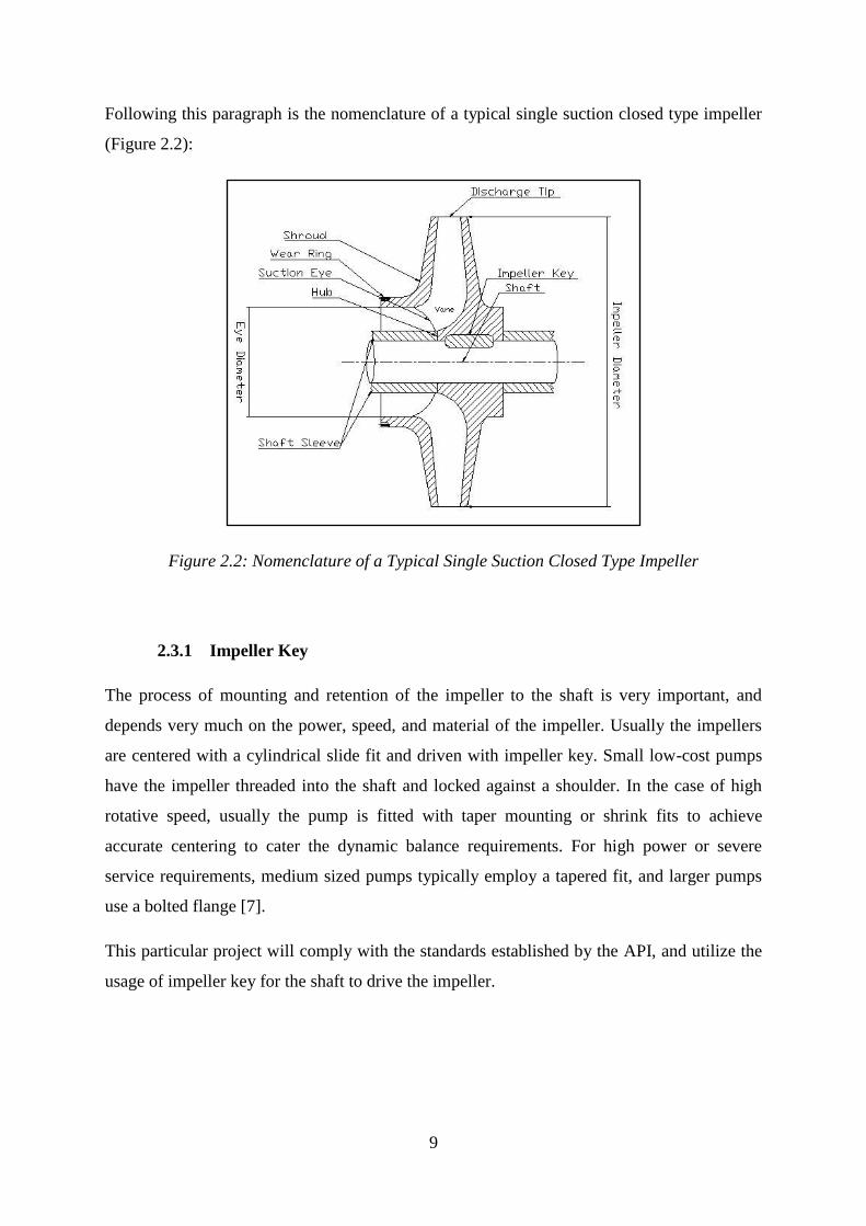
Following this paragraph is the nomenclature of a typical single suction closed type impeller
(Figure 2.2):
Figure 2.2: Nomenclature of a Typical Single Suction Closed Type Impeller
2.3.1 Impeller Key
The process of mounting and retention of the impeller to the shaft is very important, and
depends very much on the power, speed, and material of the impeller. Usually the impellers
are centered with a cylindrical slide fit and driven with impeller key. Small low-cost pumps
have the impeller threaded into the shaft and locked against a shoulder. In the case of high
rotative speed, usually the pump is fitted with taper mounting or shrink fits to achieve
accurate centering to cater the dynamic balance requirements. For high power or severe
service requirements, medium sized pumps typically employ a tapered fit, and larger pumps
use a bolted flange [7].
This particular project will comply with the standards established by the API, and utilize the
usage of impeller key for the shaft to drive the impeller.

10
2.3.2 Impeller Wear Rings
The impeller wear rings provide economical running operation to the pump. After a
justifiable period of pump operation, the running clearance between the impeller and the
pump casing will increase due to wear and tear between the duo. For an impeller not fitted
with a wearing ring, the operator of the pump can restore the original clearance by:
i. Building up the worn surfaces by welding, metal coating, spraying, etc., or [7]
ii. Purchasing a new part. [7].
Figure 2.3: Renewable Wear Rings Fitted with Threaded Dowels [7]
The fabrication of renewable wear rings (as illustrated in Figure 2.3) to the impeller
eliminates this problem, and provides an economical way to restore the original running
clearance. The wear rings can be renewed during planned preventive maintenance, or
exchanged with new ones during any breakdown.
The renewable wear rings can be fitted to the impeller by various means, being locked with
set screws, shrink fits, interference fits with pins, or slide fit with machine screws [7]. For this
particular project, the wear rings will be locked by press fit with locking pins or threaded
dowels (as specified by API Standard 610).
2.3.3 Shaft Sleeves
Shaft sleeves are incorporated into the shaft design for a variety of reasons. The most
common reasons are:
i. To provide corrosion resistance for the shaft in corrosive environments [10].

11
ii. To provide wear surfaces against packing or seals that damage shaft [10].
iii. To axially position the impeller [10].
iv. To attach a metal bellows seal onto the shaft [10].
2.4 Pump Characteristics Curve
In designing a pump, the designer must first get hold of the pump characteristics curve. The
pump characteristics curve summarizes all the important parameters to design a pump from
scratch.
As dynamic pumps, centrifugal pumps are able to deliver any capacity from zero to a
maximum depending upon the pump size, design, and suction conditions. The total head1
developed by the pump, power required to drive it, as well as resulting efficiency will vary
with capacity. The interrelations of all these parameters can be graphically summarized by
drawing the pump characteristics curve as illustrated in Figure 2.4:
Figure 2.4: Pump Characteristics Curve [3]
Probably the most important point to be observed in the curve is the Best Efficiency Point
(BEP) (as marked). The BEP points to the maximum efficiency of the operation of the pump,
and correlates the best output (in terms of pressure, capacity, and power) the pump will be
able to deliver for a particular unit of input. It is important to establish the BEP in order for
the designer to gather these information:
1 It is a common practice among pump manufacturers to use the term “head”. Head is basically an alternative
means of expressing the term “pressure rise”. Fundamentally, if a pump is claimed to have static head of 3 ft, the
pump should be able to lift the pumped fluid 3 ft above the centerline of the pump, against gravitational force.

12
The head and capacity corresponding with BEP.
The shut-off head value from head-capacity curve.
The shutoff head value is defined as the head rise from BEP (optimum correlations of
capacity2 and head) to zero capacity.
The pump curve is developed based on user’s specifications. In the case of designing a water
injection pump in petroleum industry, the characteristics of the water pumping needs will be
calculated by reservoir engineers based on reservoir conditions [11]. Among other variables
in determining the pumping pressures and flow rate are oil saturation, reservoir pressure,
produced water-oil ratio, and many others. The pumping needs will be equated in the
equation to determine basic properties of pumps, i.e. design pressures, temperatures, flow
rates, etc.
2.5 Pump Specific Speed
In developing the pump curve, the pump designer need to first design the pump’s specific
speed. Karassik, Igor J. et al. (2000) defines specific speed as: “a non-dimensional index
number which is numerically equal to the rotative speed at which an exact theoretical model
centrifugal machine would have to operate in order to deliver one unit of capacity against one
unit of total head” (p.437) [7].
It is very desirable for the designed pump to have specific speed in the range of 1000 to 3000,
as those are the range of which it will have optimum efficiency [12].
2.6 Pump Shut-Off Head
Pump shut-off head is generally defined from BEP. To illustrate the definition of shutoff
head, Figure 2.4 is referred. Based on the figure, when the pump is operating at BEP, the
corresponding head of the pump curve is 450 ft, and the capacity is 2,100 GPM. The
percentage head rise of the pump curve from BEP capacity to zero capacity is defined as the
shut-off head.
2 For this project, capacity will have the same definition as flow rate, and both terms will be used
interchangeably inside this report.

13
2.7 Shaft Sizing
Shaft sizing is very critical as it involves designing the shaft to enable it to counter fatigue,
taking into account the loads during starting, normal operation, as well as abnormal
operation. The forces involves in operation of a pump shaft includes tension, compression,
bending, and torsion. The stress produced on the shaft as a result of energy transmission from
the driver is torsion. Thus the limiting value for shaft sizing depends on the maximum
torsional stress. Because of the nature of the criticality of the high speed cyclic operation of
the pump, obviously the maximum torsional stress is kept very low than the actual shear
modulus, G, of the material, with a specific safety factor accounted [7],[3].
The values for nominal torsional stress for the design of centrifugal pump shaft as suggested
by Karassik et al. (2000) are summarized in Table 2.1:
Table 2.1: Typical Torsional Stress of Selected Material for Shaft Design [7]
Shaft Material Typical Torsional Stress – Mpa (psi)
Carbon Steel 48 (7,000)
Alloy Steel, Chrome Steel 55 (8,000)
316 Stainless Steel 35 (5,000)
2.8 Net Positive Suction Head Required
In pumping fluids, it is essential that the pressure of the liquid must not be reduced to the
vapor pressure of the liquid at the corresponding temperature. The available energy that can
be utilized to flow the liquid through the suction piping into the impeller is then defined as
the total suction head less the vapor pressure of the liquid at the pumping temperature [7].
The Net Positive Suction Head Required (NPSHR) is therefore the required net positive
suction head in order for the pump to operate at desirable condition.
2.9 Pumped Fluid
Centrifugal pumps are designed to specifically deliver a particular amount of head for a
specific type of fluid. Because of varying density and viscosity of different fluids, the same
pump will not deliver the same amount of head if subjected to different fluids. In any typical

14
offshore water injection module, there will be two types of water injected into the reservoir:
seawater or produced water (brine) from reservoir. Produced water generally contains much
higher concentration of solids than seawater does [13]. Typical specific gravity of brine
ranges from 1.02 to 1.19. Typical specific gravity of seawater at atmospheric temperature
ranges from 1.022 to 1.023 [14].
2.10 Mechanical Spare Parts Classification
In the context of inventory management, the functions of inventory can be grouped under
four major types; being raw material inventory, work-in-process inventory (WIP),
maintenance, repair and operating materials (MRO), as well as finished goods inventory [15].
The type of inventory directly related with this project is MRO. Replacement spare parts of
mechanical components are usually grouped under three major types; preventive maintenance
spare parts, critical spare parts, and insurance spare parts.
Preventive maintenance spare parts are non-critical spare parts of without which machine can
run, have high reliability, can be made or purchased in short notice, have substitutes, and/or
available in the shelf as standard parts (such as bearings) [16]. Non-critical spares are
regularly consumed during planned preventive maintenance activities.
Critical spare parts are more costly and require extra precaution in the planning and
purchasing activities. Fast (2000) defined: “A critical item is a distinct, serviceable and/or
replaceable element, part, component, assembly/subassembly, or tool, that performs a critical
function within a system or subsystem, such that in the event of its failure or omission, the
associated system/subsystem will fail to sustain its operational readiness” (p.17) [17].
Out of the three types of spare parts, insurance spares require the most careful planning due
to its high cost and extreme importance. According to Walker (1997)
“Insurance type” spares are spares for critical parts which are essential for the
operation of the system in which they serve, and which have an appreciable
probability of not needing replacement during the lifetime of the system. (p.1) [18].

15
2.11 The Design Process
The design and manufacturing process of any tool or equipment is an integrative procedure.
Most of the designs started from a concept, before being transformed into preliminary design,
and subsequently manufactured as a complete instrument [19]. More recent development in
technology has introduced the concept of modeling or prototyping into design procedures
[19].
A concept is an idea for the development of any new product or improvement of an old
product [19]. In the phase of preliminary design, the designer established the feasibility of the
product through various means, such as discussion, survey, or presentation [19]. Once a
design has been approved, it is necessary to fabricate a prototype to examine the design.
Gebhardt (2003) defined prototype as a close resemblance of the sample; produced according
to production documents, whereas the only difference between a prototype and a product lies
in the production process (p.16) [20].
Sometimes it is necessary to execute a short run production; to further proof a part before the
mass production stage is commenced [19]. In the mass or final production stage, parts are
processed (machined, injection molded, or cast) in large numbers [19]. The extensive stages
undergone before mass production is started are supposed to ensure zero or minimal defects
in the final product, to avoid substantial loss to the organization.
The product formation time is the duration between the first conceptualization of the new
product and its series production, as illustrated in Figure 2.5 [20]:
Product Formation
Production Tool
Manufacturing
Manufacturing /
Part Production
Production Tool
Development
Product Development
Figure 2.5: Elementary Steps of Product Formation [20]
The duration of the formation of any product should take into account not only the product
design and manufacturing interval, but the time spent to manufacture the tools as well. This
(tool design and development) will clearly add to the time and effort expended to develop our
product. To add to that fact, traditional means of fabrication of prototypes (such as
16
machining) could consume up to four weeks or more, depending on the level of complexity
and representativeness [21].
2.12 Rapid Prototyping
According to Heizer et al., (2006), one of the direction of operations management is to
promote rapid product development; operations managers should respond to technology that
are faster and alliances that are more effective (p.12) [22]. This is one of the reasons why
rapid prototyping even existed [23].
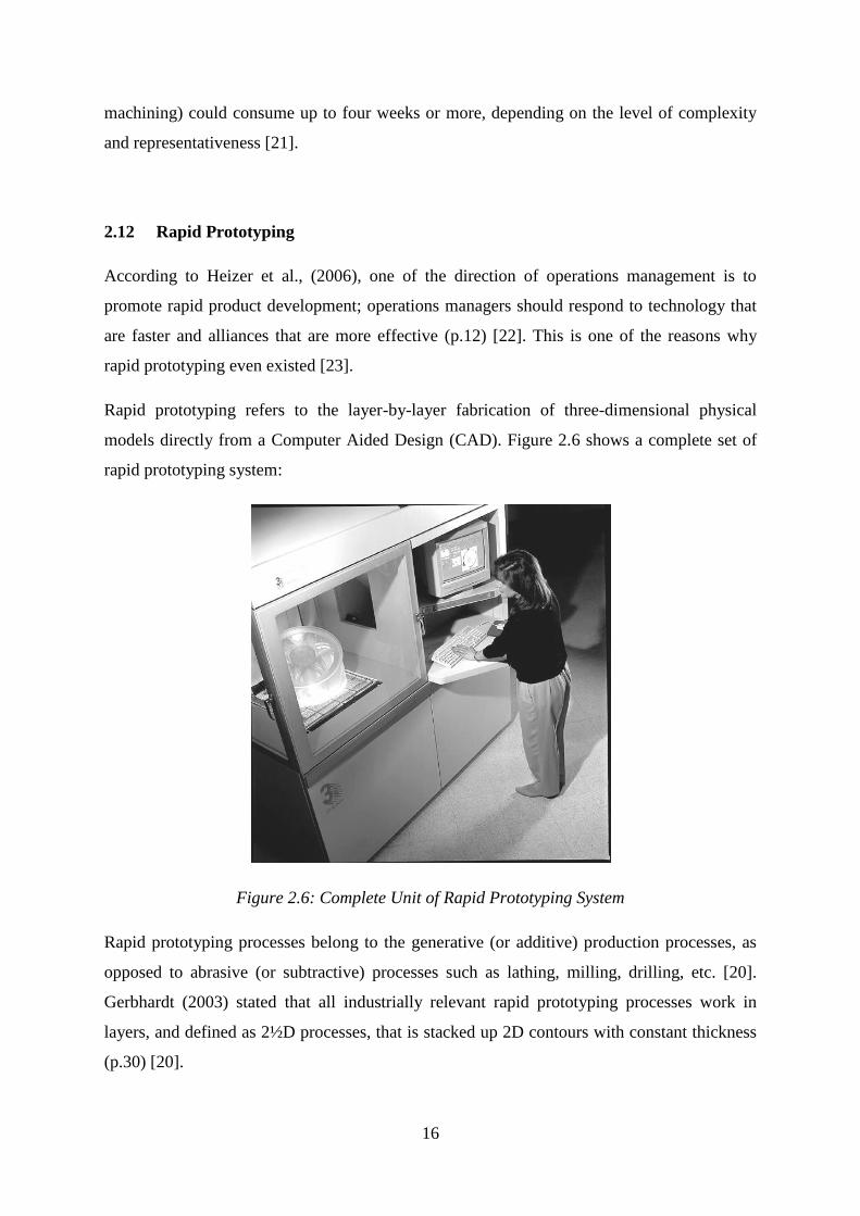
Rapid prototyping refers to the layer-by-layer fabrication of three-dimensional physical
models directly from a Computer Aided Design (CAD). Figure 2.6 shows a complete set of
rapid prototyping system:
Figure 2.6: Complete Unit of Rapid Prototyping System
Rapid prototyping processes belong to the generative (or additive) production processes, as
opposed to abrasive (or subtractive) processes such as lathing, milling, drilling, etc. [20].
Gerbhardt (2003) stated that all industrially relevant rapid prototyping processes work in
layers, and defined as 2½D processes, that is stacked up 2D contours with constant thickness
(p.30) [20].

17
The development of rapid prototyping technology has a major relation to the advances in the
application of computers in the industry. Started with Computer Aided Design (CAD) the
technology preceded to Computer Aided Manufacturing (CAM), and Computerized
Numerical Control (CNC) machine tools; all of those technology are crucial in the
development of rapid prototyping systems [21].
The technology of rapid prototyping has many advantages, being [23]:
i. Enables the user experiment with physical objects of any complexity.
ii. Enables designer to increase complexity of their designs with little effect on lead
time and cost.
iii. Presents new capabilities and opportunities to the marketers.
iv. Enables consumer to purchase products which meet more closely individual needs
and wants.
There are several means of generation of the model using rapid prototyping; the first being
solidification of liquid materials photopolymerization –Stereolithography (SL), in which the
underlying mechanism is solidification of monomer liquids [19],[20]. The liquids are exposed
to ultraviolet radiation which sets off a spontaneous polymerization, transforming the liquid
to solid polymer [20].
The other means is generation from solid phase which includes melting and solidification of
powder and granules – Laser Sintering (LS). In LS process, powders or granules are arranged
in a powder bed to be melted together by solid beam [20]. There is also a method called LLM
or Layer Laminate Manufacturing, where the 3D model is split into 2D contoured layers, cut,
and then assembled into 3D models [20]. In Fused Layer Modeling (FLM), solid wire-shaped
materials of semimolten consistency are melted in a heated single- or a multi-nozzle system
and deposited geometrically defined into a structure. In Laser Chemical Vapor Deposition
(LCVD), matter from gaseous phase is solidified into solid [20].
On top of everything, rapid prototyping is a more economically viable means of producing
prototypes compared to other conventional means, given the circumstances that the model is
complex and the shortest possible time is the utmost importance for the product’s position,
market-wise or application-wise [20].

18
2.13 Casting Processes
Casting generally means the process of pouring molten metal into a mold, where the metal
takes the shape of the mold as it solidifies. In the broad term of casting, various processes
have been developed to fully utilize the means of casting based on their respective
applications. These processes can be grouped into three major process groups: sand casting,
die casting, and investment casting [24]. Through most of the history of casting, the term
“casting” itself has primarily been associated with sand moulding [24]. The sand casting
process however, lacks in terms of the precision, and further process enhancement has been
developed to cater this particular issue. The advent of die casting met some of the criteria for
enhanced precision; however this group of techniques has its own limitations, most notably in
the compatibility of alloys with the molds, as well as the shapes capable of being produced
and extracted from the mold at sensible cost [24].
According to Beeley (1995)
The concept of precision is seen to embrace, not only the aspect of dimensional
accuracy and tolerances, but also surface quality and capability to produce intricate
cast detail; either of the latter can be the critical factor in the choice of a forming
process for a particular application (p.2) [24].
Due to the physical characteristics and quality of the molds themselves, sand casting and die
casting processes inhibit the fabrication of intricately-shaped products.
2.13.1 Investment Casting
The process of investment casting involves the formation of an expendable pattern; in an
expendable ceramic mold [24], [25]. Generally, the pattern is made of wax by injection
molding and assembled in clusters around a common sprue and feeder system (similarly
formed in wax) [24]. The pattern is then dip coated in investment slurry, beginning with
primary coat, before further dipped to build the mold thickness [24]. Special heating
condition is employed in the dewaxing stage, to avoid shell cracking. The molten metal is
then poured into the mold and allowed to solidify. The mold cavity is in one piece, as well as
the final part [25].
19
The investment casting process has the following advantages, as opposed to other casting
methods:
i. Complex-shaped parts can be produced close to final configuration [25].
ii. Tighter dimensional tolerances are achievable [25].
iii. Fewer finishing methods are required [25].
iv. Casting has better quality and less porosity [25].
2.13.1.1 Investment Casting Material
The investment casting industry has gown radically over the last sixty years, and the range of
alloys compatible with the process is wider than that associated with many other casting
processes [24]. For this particular project, the alloy used is Sus. 304.
Grade 304 is the most versatile and most widely used stainless steel than any other [26]. This
particular grade of alloy has excellent corrosion resistance characteristics and good oxidation
resistance in intermittence service [26].
The extensive material properties and description of Grade Sus. 304 is enclosed in this report
as APPENDIX I [26].

20
3 METHODOLOGY
3.1 Research Methodology
Throughout the completion of this project, the author had accomplished three major
milestones in conjunction with the project’s objectives. They are:
a. Impeller design and modeling.
b. Impeller prototyping and manufacturing.
c. Costs-time benefit analysis.
The sub-methodologies and procedures of each of these major milestones are illustrated in
the subsequent subsections.
The Gantt-chart representing the flow of activities approached in this project is included in
this report as APPENDIX II.
3.2 Impeller Design and Modeling
3.2.1 Data Acquisition and Pump Characteristics Curve
Prior to doing the calculation of designing the impeller, the specifications of the pump were
first defined. The definition of pump specifications followed actual parameters on existing
water injection module of an actual oil field. The essential information in defining the
specifications of the pump are:
a. Suction Pressure.
b. Discharge Pressure.
c. Design Capacity.
The specification definition of the pump will be further defined by these preceding
procedures:
Selection of Rotating Speed.
Pump Head and Stages Definition.
Pump Specific Speed Definition.
Pump Shutoff Head Definition.
Development of Pump Characteristics Curve.

21
3.2.2 Impeller Design
Once the pump characteristics curve is developed and essential data is compiled, the impeller
design phase commenced. The methodology of impeller design followed the procedures
described by Lobanoff V. S. et al., (1992) [10]. The procedures of designing the impeller are
summarized as:
i. Selection of vane number and discharge angle.
ii. Calculation of impeller diameter.
iii. Calculation of impeller width.
iv. Determination of eye diameter.
v. Determination of shaft diameter under impeller eye.
vi. Estimation of impeller eye area.
vii. Estimation of Net Positive Suction Head Required (NPSHR).
viii. Determination of volute diameter.
ix. Impeller construction layout.
3.2.3 Impeller Modeling
In the modeling phase, the calculated and defined parameters of the impeller were gathered
and interpreted. Using appropriate Computer Aided Design (CAD) software, the numerically
designed impeller is translated into a virtual three-dimensional model.
3.2.4 Equipment and Apparatus
i. Autodesk® AutoCAD 2005
® software. From this point on this particular software
will be referred to as “AutoCAD” only.
3.3 Impeller Prototyping and Manufacturing
3.3.1 Impeller Rapid Prototyping
The result of CAD modeling activity under design and modeling phase of the impeller was
converted to a rapid prototyping compatible file format, *.stl file. Most of CAD modeling

22
software have built-in file converter to enable the file to be stored in *.stl format. A rapid
prototyping system will directly recognize an *.stl file therefore eliminating any further
adjustment to be made on the particular file.
The process of prototyping the designed impeller using rapid prototyping technology
consumed less than 6 hours. For this particular Thermojet Solid Object Printer, every layer
formed is 0.0016 in thick (approximately 40 microns). The concept used by Thermoject Solid
Object Printer is multi jet modeling, where the thermoplastic wax is heated and the prototype
is built layer by layer from bottom up. The procedures of prototyping are as explained below:
i. The Allegro Client Manager software was executed from the workstation.
ii. The file of the designed impeller CAD drawing, from *.stl format, was submitted
to Thermojet Client® software.
iii. The model appeared in the software.
iv. The model was viewed in 3D and 2D setting.
v. The model was offset manually in the software to correctly place it inside the
printing region.
vi. The original model of the impeller has a diameter of 11.486 in. For printing
purposes, it was scaled down to 50% for reasons described below 3.
vii. The drawing was submitted to Thermojet Solid Object Printer.
viii. Thermojet Solid Object Printer warmed up for approximately 15 minutes.
ix. Thermojet Solid Object Printer started head cleaning procedures for
approximately two minutes.
x. Thermojet Solid Object Printer started depositing the first layer of the prototype.
xi. Thermojet Solid Object Printer finished printing after approximately 4 hours 40
minutes.
xii. The prototype was post-processed; where support materials were manually
removed from the prototype.
3 For prototyping processes, the model was scaled down to half its original size because:
i. The maximum extension of prototype in the y-axis is 250 mm (9.847 in). This machine is
incapable of producing the impeller at 100% scale.
ii. Due to the fact that the prototype is to be further casted, it is economically more viable to have a
scaled down model so less financial capital would have to be allocated for the manufacturing
processes.
iii. It is not cost-effective to produce a larger metallic prototype of the impeller, should investment
casting is to be selected for further manufacturing scopes; for this final year project involves a
consideration of cost constraint.

23
xiii. Arbitrary dimensions were recorded from the prototype to measure error.
xiv. Error in the prototyping process was analyzed.
3.3.2 Impeller Investment Casting
For the fabrication of metallic model of this impeller, investment casting technology is
employed. Other casting processes will have problems in forming this particular impeller,
because this impeller incorporates a series of internal structures and internal passageways, as
illustrated in Figure 3.1. Due to the fact that investment casting employs a usage of
expendable pattern and expendable mold, therefore this process will have minimized problem
in coming up with the internal structures.
Figure 3.1: Internal Structures and Passageways on the Impeller
The investment casting procedures subsequently follows after the completion of rapid
prototyping processes:
i. The rapid prototyped impeller wax pattern was assembled with natural wax
having the shape of sprue and feeder system (as illustrated in Figure 3.2).
ii. The assembled wax pattern was coated in investment ceramic material (single
coating)4.
4 The wax pattern was single coated; as opposed to multi-coating for ideal casting processes; this is due to the
fact that the third party company, Primametals Sdn. Bhd., offers to absorb the cost of casting processes, and
carry out the casting procedures free of charge.
Single coated ceramic molds might impose problems on the prototype, as there is a possibility for defects due to
formation of void cavity or air bubbles inside the molds. However due to the fact that the impeller is only cast to
prove its castability and feasibility; the risk of getting a defect impeller is acceptable. The impeller is not to be
further used in an operating pump nor be subjected to experimental testing.
Internal Structures
Internal Passageways

24
iii. The process of dewaxing followed (removal of the wax from the cavity).
iv. Molten metal (Sus. 304) is poured into the cavity, and allowed to solidify through
cooling.
v. The mold was broken to recover the metallic impeller.
vi. Finishing operation commenced.
Figure 3.2: Pattern Assembly
3.3.3 Dimensional Error Analysis
Arbitrary dimensions of both the rapid prototyped wax pattern and investment cast metallic
prototype are taken and compared with the actual dimension of the CAD model. Variations in
the dimensions between the prototypes and the CAD model are calculated to study the error
of the manufacturing processes.
3.3.4 Equipment and Apparatus
For rapid prototyping procedures, these equipments and apparatus are used:
i. Workstation.
ii. Thermojet Client® Software Version 1.01, ©3D Systems, Inc.
iii. Thermojet Solid Object Printer.
iv. Thermoplastic wax as the raw material of the prototype.
Impeller Pattern; Rapid
Prototyped
Sprue and Feeder
System, Natural Wax
25
v. Manual post-processing tools:
a. A scalpel.
b. A rigid wire.
c. A screwdriver.
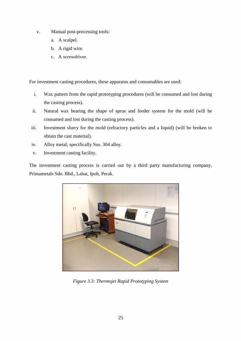
For investment casting procedures, these apparatus and consumables are used:
i. Wax pattern from the rapid prototyping procedures (will be consumed and lost during
the casting process).
ii. Natural wax bearing the shape of sprue and feeder system for the mold (will be
consumed and lost during the casting process).
iii. Investment slurry for the mold (refractory particles and a liquid) (will be broken to
obtain the cast material).
iv. Alloy metal; specifically Sus. 304 alloy.
v. Investment casting facility.
The investment casting process is carried out by a third party manufacturing company,
Primametals Sdn. Bhd., Lahat, Ipoh, Perak.
Figure 3.3: Thermojet Rapid Prototyping System

26
3.4 Costs-Time Benefit Analysis
A costs-time benefit analysis was carried out to investigate the project’s favorability in terms
of costs and lead-time delivery. The activities carried out under this objective were:
a. Data acquisition on actual costs and lead-time delivery from OEM of generally
equivalent mechanical replacement part as studied in this project was conducted.
b. Analysis was carried out by calculating and putting in comparison the costs and lead-
time delivery of both approaches (this project and procurement through OEM).
c. The results of the analysis were graphically represented in the form of graphs.
27
4 RESULTS AND DISCUSSIONS
4.1 Impeller Design
4.1.1 Data Acquisition
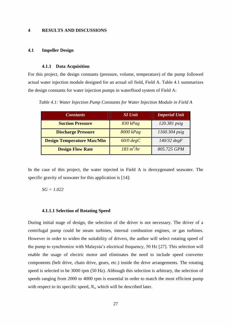
For this project, the design constants (pressure, volume, temperature) of the pump followed
actual water injection module designed for an actual oil field, Field A. Table 4.1 summarizes
the design constants for water injection pumps in waterflood system of Field A:
Table 4.1: Water Injection Pump Constants for Water Injection Module in Field A
Constants SI Unit Imperial Unit
Suction Pressure 830 kPag 120.381 psig
Discharge Pressure 8000 kPag 1160.304 psig
Design Temperature Max/Min 60/0 degC 140/32 degF
Design Flow Rate 183 m3/hr 805.725 GPM
In the case of this project, the water injected in Field A is deoxygenated seawater. The
specific gravity of seawater for this application is [14]:
SG = 1.022
4.1.1.1 Selection of Rotating Speed
During initial stage of design, the selection of the driver is not necessary. The driver of a
centrifugal pump could be steam turbines, internal combustion engines, or gas turbines.
However in order to widen the suitability of drivers, the author will select rotating speed of
the pump to synchronize with Malaysia’s electrical frequency, 50 Hz [27]. This selection will
enable the usage of electric motor and eliminates the need to include speed converter
components (belt drive, chain drive, gears, etc.) inside the drive arrangements. The rotating
speed is selected to be 3000 rpm (50 Hz). Although this selection is arbitrary, the selection of
speeds ranging from 2000 to 4000 rpm is essential in order to match the most efficient pump
with respect to its specific speed, Ns, which will be described later.

28
4.1.1.2 Pump Head and Stages
The pump head for this application is defined as:
H = Head in feet
∆P = Pressure difference, discharge – suction in psia
In order to have specific speed Ns inside a desired range, the head must be in the range of 200
to 800 ft, which will incorporate multistage pump concept for this particular design. The
author has chosen the implementation of seven stages (seven impellers) horizontal pump, to
meet the desired pressure design. The seven stages will be designed to carry same amount of
head, which will leave each stage with:
Hn-stg = Head for a stage-n in feet
From this point onwards, calculations will be focused on developing the impeller for the first
stage of the pump. The word “pump” will refer to the first stage and first stage impeller of the
pump, where applicable.
4.1.1.3 Pump Specific Speed
The specific speed for this particular pump stage (or impeller) will be:
Ns = Specific speed
n = Impeller speed in rpm
Q = Capacity in GPM
From Chart of Efficiency of Pumps versus Specific Speed by Tuzson J.,(2000) [12], the
correlative pump efficiency with respect to Ns = 1085.592 and Q = 805.725 GPM is:
η = 77 %
This chart is enclosed in this report as APPENDIX III.

29
4.1.1.4 Pump Shut-Off Head
This particular pump will be designed to have continuously rising characteristics, in which
the head (pressure ratio) rises continuously as the capacity of the pump is decreased [7]. The
selection of shut-off head and characteristics is important for the design to commence. It is
typical for many pumps to have shut-off head value from BEP as 20 %, thus this pump will
follow that particular value [4].
For this project, as the optimum (BEP) value of head at Q = 805.725 GPM is H = 335.787 ft,
for 20% shut-off from BEP, it is assumed theoretically that its head at Q = 0 GPM is:
4.1.1.5 Pump Characteristics Curve
From the values and data gathered:
BEP equals to 77%.
At BEP, the pump conditions are as follows:
o Head = 335.787 ft
o Capacity = 805.725 GPM
The pump characteristics curve is of continuously rising type, having zero capacity
head of 20% higher than BEP head.
These values and information is equated to develop the Pump Characteristics Curve5:
5 The development of the pump curve should be based on experimental results. However, in the design phase, it
is necessary to first define the operating condition at points BEP and at zero capacity [10]. This will define the
shutoff head, and is necessary to proceed with determination of number of impeller vanes [10].

30
Figure 4.1: Pump Characteristics Curve with BEP marked.
4.1.2 Impeller Numerical Design
The procedures to numerically design the impeller followed the steps defined earlier in the
methodology. In order to design the impeller, raw data (design constants such as pressure,
flowrate, etc.) were plugged in into a series of equation and established constant graphs. The
results of these procedures are summarized in Table 4.2:
Table 4.2: Numerical Results for Impeller Design
Procedures Parameters Results
1 Vane Number [3] 6
2 Discharge Angle [3] 25°
3 Impeller Diameter [3] 11.486 in
4 Impeller Width [3] 0.578 in
5 Eye Diameter [3] 5.169 in
6 Shaft Diameter under Impeller Eye [7], [3], [28],
[29], [30]
2.375 in
7 Shaft Sleeve Diameter [29] 2.78 in
8 Impeller Eye Area [3] 14.915 in2
9 Net Positive Suction Head Required (NPSHR) [3] 22.7 ft
10 Volute Throat Area [3] 3.908 in2
The extensive procedures of numerical design stage of the impeller are described in this
report in APPENDIX IV.

31
4.2 Impeller Modeling
4.2.1 Plan View Development
Refer Figure 4.3. The impeller width b2 is laid out at impeller full diameter. The hub and
shroud profile were developed by expanding the width approximately 5º on each side. The
profile change from discharge towards suction is kept as gradual as possible using AutoCAD.
The hub is developed with thickness of 0.2025 in to incorporate the shaft sleeve.
4.2.2 End View Development
Refer Figure 4.3. A circle to full impeller diameter was drawn. The circle was divided into 24
segments (of 15º each) to enable the iteration of the vane in the later part of the drawing.
4.2.3 Impeller Inlet Angles
Figure 4.2: Impeller Inlet Angles
Vane inlet angle (in this case 17º) was established from a layout of velocity triangle, as
shown in Figure 4.2. The vector connecting Ut and Cm1 represents suction angle of flow. Inlet
vane angle B1 is drawn to intersect Ps1, and for optimum NPSH it is recommended that Ps1 =
1.05 to 1.2 times Cm1 [3].
4.2.4 Impeller Vane Development
Refer Figure 4.3. The procedures of impeller vane development started with the drawing of a
line equal to discharge angle. On the end view the distance ar was estimated and located. ar is

32
transmitted to discharge angle line on the vane development establishing the distance a. a is
transmitted to the plan view and R1 is measured consequently. R1 is transferred back to end
view to see if the established ar is correct. Lobanoff et al. suggested a trial and error method
in establishing these points and measurements.
Figure 4.3: Two Dimensional Drawing of Impeller End View, Plan View, and Vane
Development
The author however, came up with a simplified iterative approach to come up with the best
assumptions in establishing the points:
Figure 4.4: Iterative Solutions for Impeller End View Development, Point 1 to 4
R1a is a subject of ar by this equation:

33
R1b is also a function of ar by this equation:
The iterative procedures are carried out with ar as the variable. The resultant value of R1a and
R1b is compared and the value of ar which yields percentage difference of R1a and R1b of less
than is used. The iteration is continued, substituting the value of accepted R1 into
R for the second point, R2 into R1 for the third point, until the point no. 4, where the
minimum impeller cut diameter is reached. The iteration procedures of all the four points are
enclosed in this report as APPENDIX V.
The position of point 5 until 6 follows trial and error method, for the impeller shroud is no
longer uniform at 5º, and the vane development is gradually altered to fit the suction vane
angle.
4.2.5 Vane and Shroud Thickness
Based on the guidelines published by Lobanoff et al, the thickness of the vanes and shroud is
to follow a minimum size for castability and optimum efficiency [3]. For this particular
design, the thicknesses of those components are summarized in Figure 4.5 and Table 4.3:
Figure 4.5: Guidelines for Vane and Shroud Thickness [3]

34
Table 4.3: Guidelines for Vane and Shroud Thickness [3]
Minimum Vane Thickness, in Minimum Shroud Thickness, in
Outer Diameter Middle Inlet t1 t2
1/4 3/8 3/16 5/32 5/16
The completed two dimensional vane of the impeller is shown in Figure 4.6:
Figure 4.6: Impeller End View, with Vane Thickness Completed
Using _array (polar array) command in AutoCAD, the vanes are arrayed to fill six items in a
360° horizon inside the impeller.
4.2.6 Impeller Shroud Development
From the Plan View, using the command _revolve in AutoCAD, the front and back shroud
are revolved about their center (shaft centerline). Refer Figure 4.7 for details.
Two-Dimensional Front and Back Shroud. Revolved, Three-Dimensional Front and Back
Shroud.
Figure 4.7: Impeller Shroud Development

35
4.2.7 Three Dimensional Vane Development
From the established two dimensional End View, the vane is extruded to a height exceeding
the impeller width. Using Boolean operations, the impeller and vanes are added (union). The
excess vanes are then cut (subtract) from the needed impeller. Refer Figure 4.8 for details:
Impeller and Vanes: Union Impeller and Vanes with Excess Vanes
Subtracted
Figure 4.8: Union of Impeller Shrouds and Vanes, and Subtraction of Excess Vanes,
Resulting in Completed Impeller Model
The basic dimension of the impeller model is shown in Figure 4.9:
Figure 4.9: Impeller Model with Dimensions

36
4.3 Impeller Prototyping and Manufacturing
4.3.1 Data Transmission
The STL file submitted into the Thermojet Client® software was successfully uploaded into
the program and the layout display is as shown in Figure 4.10. The Virtual model of the
impeller as drawn by AutoCAD is as shown in Figure 4.11 for comparison purposes.
Figure 4.10: Designed Impeller Layout Display on Thermojet Client®
Software
Figure 4.11: Designed Impeller Layout Display on Autodesk®
AutoCAD 2005®

37
4.3.2 Rapid Prototyped Model
The rapid prototyped model was obtained after approximately 4 hours and 40 minutes of
rapid prototyping procedures. The prototype was full of support materials, as shown in Figure
4.12:
Figure 4.12: Raw Prototype of the Designed Impeller
During post processing, fragile support materials are manually removed by hand, using basic
tools as described is Chapter 3. The illustration of the process is shown in Figure 4.13:
Figure 4.13: Post-processing of Rapid Prototyped Impeller.
38
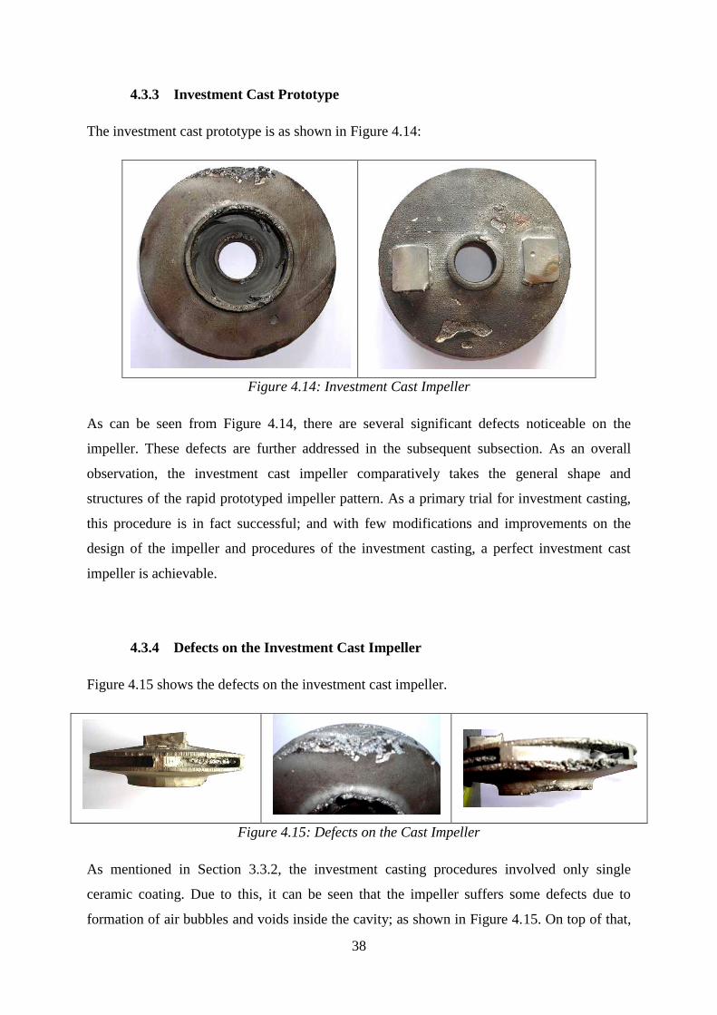
4.3.3 Investment Cast Prototype
The investment cast prototype is as shown in Figure 4.14:
Figure 4.14: Investment Cast Impeller
As can be seen from Figure 4.14, there are several significant defects noticeable on the
impeller. These defects are further addressed in the subsequent subsection. As an overall
observation, the investment cast impeller comparatively takes the general shape and
structures of the rapid prototyped impeller pattern. As a primary trial for investment casting,
this procedure is in fact successful; and with few modifications and improvements on the
design of the impeller and procedures of the investment casting, a perfect investment cast
impeller is achievable.
4.3.4 Defects on the Investment Cast Impeller
Figure 4.15 shows the defects on the investment cast impeller.
Figure 4.15: Defects on the Cast Impeller
As mentioned in Section 3.3.2, the investment casting procedures involved only single
ceramic coating. Due to this, it can be seen that the impeller suffers some defects due to
formation of air bubbles and voids inside the cavity; as shown in Figure 4.15. On top of that,
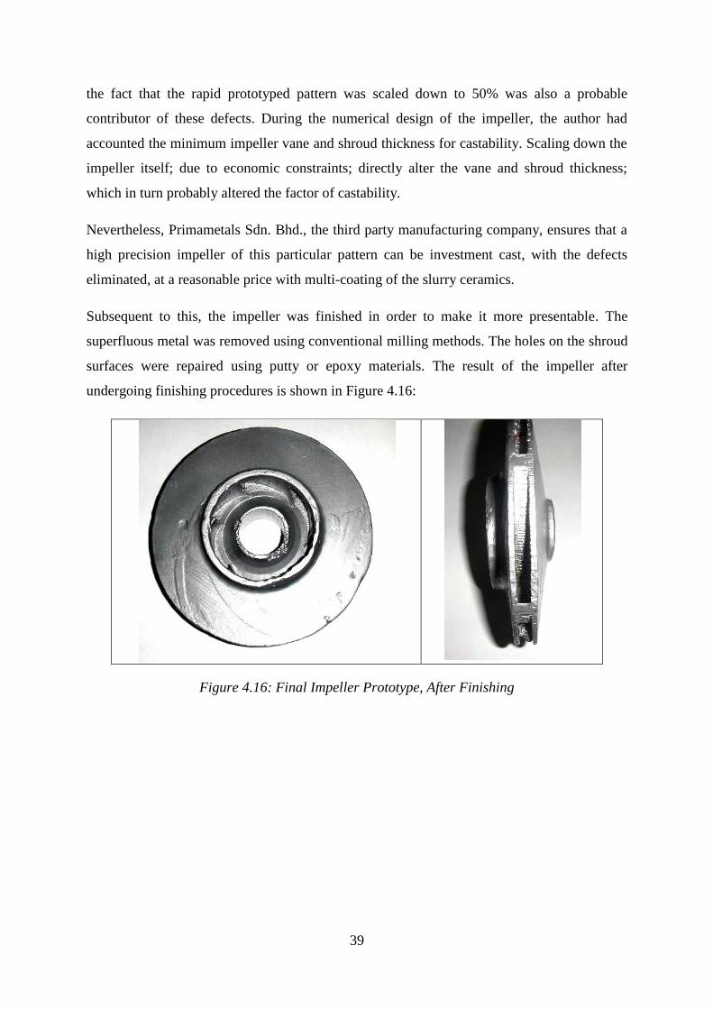
39
the fact that the rapid prototyped pattern was scaled down to 50% was also a probable
contributor of these defects. During the numerical design of the impeller, the author had
accounted the minimum impeller vane and shroud thickness for castability. Scaling down the
impeller itself; due to economic constraints; directly alter the vane and shroud thickness;
which in turn probably altered the factor of castability.
Nevertheless, Primametals Sdn. Bhd., the third party manufacturing company, ensures that a
high precision impeller of this particular pattern can be investment cast, with the defects
eliminated, at a reasonable price with multi-coating of the slurry ceramics.
Subsequent to this, the impeller was finished in order to make it more presentable. The
superfluous metal was removed using conventional milling methods. The holes on the shroud
surfaces were repaired using putty or epoxy materials. The result of the impeller after
undergoing finishing procedures is shown in Figure 4.16:
Figure 4.16: Final Impeller Prototype, After Finishing
40
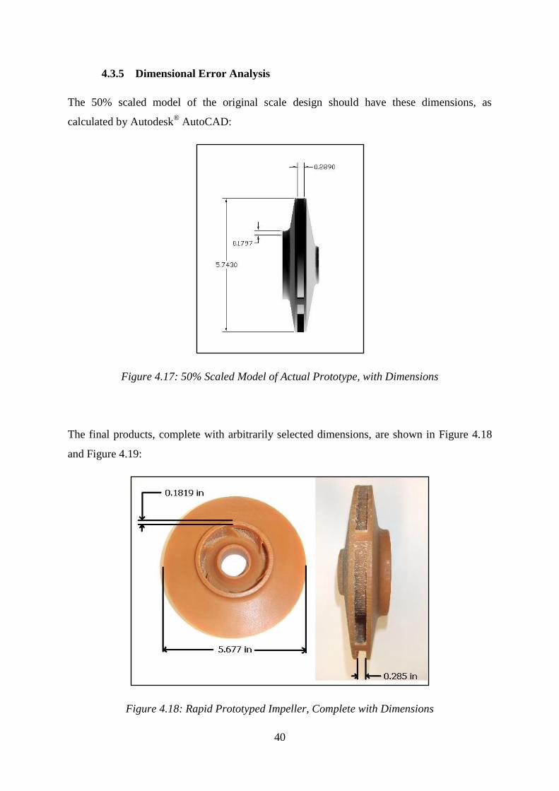
4.3.5 Dimensional Error Analysis
The 50% scaled model of the original scale design should have these dimensions, as
calculated by Autodesk® AutoCAD:
Figure 4.17: 50% Scaled Model of Actual Prototype, with Dimensions
The final products, complete with arbitrarily selected dimensions, are shown in Figure 4.18
and Figure 4.19:
Figure 4.18: Rapid Prototyped Impeller, Complete with Dimensions

41
Figure 4.19: Investment Cast Impeller, Complete with Dimensions
By referring to Figure 4.7 to Figure 4.9; there are deviations or errors of the rapid prototyped
model and investment cast model from the CAD model. These errors are analyzed and
summarized in Table 4.4 below:
Table 4.4: Error Analysis; Comparison of Prototype Dimensions and Actual Dimensions
No. Item CAD Model
(in)
RP Pattern
(in)
Cast Prototype
(in)
RP Deviation
(%)
Cast Deviation
(%)
1 Impeller Diameter 5.743 5.677 5.548 1.15 3.40
2 Impeller Width 0.289 0.285 0.265 1.38 8.30
3 Suction Lip Thickness 0.1797 0.18189 0.178 1.22 0.95
Avg. Deviation 1.25 4.22
For the rapid prototyped impeller, having an error of less than 2% is relatively very small.
Therefore it is desirable to implement rapid prototyping technology in circumstance where
precision is of major importance.
In the case of the investment cast impeller, there are slightly higher deviations as compared to
the CAD model. Part of these deviations is result of the deviations of the rapid prototyped
(RP) impeller, as the RP impeller was directly used as the pattern for the investment casting
process. The deviations could be further explained by the phenomena of metal shrinking,
where the molten metal reduces its size through solidification during the casting process. In

42
the process of casting the actual impeller, these phenomena and deviations must be accounted
for in the CAD designing procedures.
It could also be noted that for the investment cast prototype, the dimensional error of the
impeller width is significantly bigger than the other two items. This could be explained by the
fact that the casting process may yield different dimensional accuracy with different planes.
4.4 Costs-Time Benefit Analysis
With the established objectives as illustrated in Chapter 1, cost-time benefit analysis was
carried out and the results are illustrated as follows:
Table 4.5 shows detailed raw material data consumed in this project used as the basis of the
calculation of the cost-time benefit analysis:
Table 4.5: Raw Material Properties for Rapid Prototyping and Investment Casting
No. Item Raw Material Density (kg/m3)
1. Rapid Prototyping (RP) Wax Thermojet 88 975
2. Investment Casting Metal Sus. 304 8000
The geometrical properties of the rapid prototyped and investment cast prototype are as
shown in Table 4.6.
Table 4.6: Geometrical Properties of Rapid Prototyping Wax Impeller and Investment Cast
Impeller, Half-scaled and Actual Size
No. Item 50% Scaled Model Actual Size Model
1. Volume (in3) 11.1037 88.8296
2. Volume (m3) 1.81957 x 10
-4 1.45566 x 10
-3
3. Mass, Thermojet 88 (kg) 0.182 1.419
4. Mass, Sus. 304 (kg) 1.456 11.645
Table 4.7 illustrates the unit costs of manpower and materials used for the completion of this
project.

43
Table 4.7: Process and Manpower Costs per Unit of the Design and Development of the
Centrifugal Pump Impeller using Rapid Prototyping and Investment Casting
No. Item Cost (RM)
1. Rapid Prototyping wax. Cost per kg. 1,400.00
2. Investment casting process cost (manpower + procedures + raw
material). Cost per kg.
30.82
3. Manpower cost for impeller numerical design (Engineer). Cost per day. 200.00
4. Manpower cost for CAD model development (Engineer). Cost per day. 200.00
5. Manpower cost for Rapid Prototyping model development (Engineer).
Cost per day.
200.00
As illustrated in Section 3.3.1, the actually fabricated rapid prototyping impeller pattern is
reduced to 50% of its original size. The structure of the impeller produced from rapid
prototyping consists of actual impeller and support materials, as illustrated in Section 4.3.2.
The distribution of mass of each structure of the impeller is as illustrated in Table 4.8:
Table 4.8: Distribution of Mass of Actual Impeller Structure and Support Materials of Rapid
Prototyped Impeller Pattern
No. Structure Mass (g) Percentage (%)
1. Total (Impeller + Support) 292 100
2. Actual Impeller 182 62.33
3. Support Materials 110 37.67
Table 4.9 to 4.10 exemplifies the total costs and time consumed for the design and
development of the impeller using the approaches applied in this project.
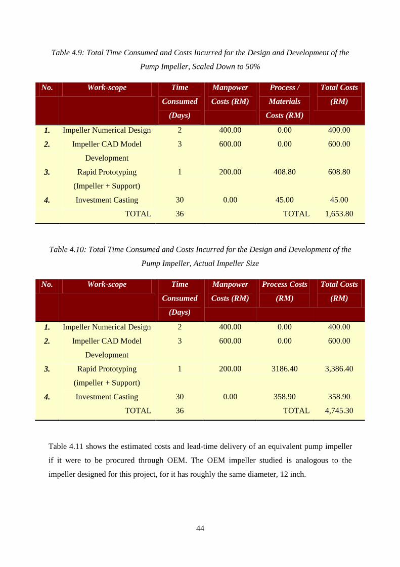
44
Table 4.9: Total Time Consumed and Costs Incurred for the Design and Development of the
Pump Impeller, Scaled Down to 50%
No. Work-scope Time
Consumed
(Days)
Manpower
Costs (RM)
Process /
Materials
Costs (RM)
Total Costs
(RM)
1. Impeller Numerical Design 2 400.00 0.00 400.00
2. Impeller CAD Model
Development
3 600.00 0.00 600.00
3. Rapid Prototyping
(Impeller + Support)
1 200.00 408.80 608.80
4. Investment Casting 30 0.00 45.00 45.00
TOTAL 36 TOTAL 1,653.80
Table 4.10: Total Time Consumed and Costs Incurred for the Design and Development of the
Pump Impeller, Actual Impeller Size
No. Work-scope Time
Consumed
(Days)
Manpower
Costs (RM)
Process Costs
(RM)
Total Costs
(RM)
1. Impeller Numerical Design 2 400.00 0.00 400.00
2. Impeller CAD Model
Development
3 600.00 0.00 600.00
3. Rapid Prototyping
(impeller + Support)
1 200.00 3186.40 3,386.40
4. Investment Casting 30 0.00 358.90 358.90
TOTAL 36 TOTAL 4,745.30
Table 4.11 shows the estimated costs and lead-time delivery of an equivalent pump impeller
if it were to be procured through OEM. The OEM impeller studied is analogous to the
impeller designed for this project, for it has roughly the same diameter, 12 inch.

45
Table 4.11: Estimated Cost and Lead-time Delivery of a 12-inch Diameter Pump Impeller,
Procured through Original Equipment Manufacturer
1. Price (RM) 48,000.00
2. Lead-time Delivery (Days) 112 - 168
Table 4.12 demonstrates the comparison of this project and procurement through OEM in
terms of lead-time delivery and costs.
Table 4.12: Comparison of Procedures Approached in This Project with Procuring Spare
Parts through Original Equipment Manufacturer (OEM)
No. Description Lead-time Delivery
(Days)
Costs (RM)
1. This Project
Design and Manufacturing 36 4,745.30
2. Manufacturing Only 31 3,745.30
3. Procuring Spares through OEM 112-168 48,000.00
The verification documents of the figures shown in section 4.4 can be accessed in this report
as APPENDIX VI
The graphical representation of the results shown in Table 4.11 illustrating the comparison of
procurement through approaches adopted in this project and procurement through OEM in
terms of costs and lead time delivery is shown in Figure 4.20.
It can be clearly seen from the graph how dramatically reduced are the costs and lead-time
delivery of the impeller (representing mechanical replacement parts) if somehow the
procurement process were to be shifted from conventional means (through OEM) to the
procedures studied in this project. These reductions can be explained by the fact that the
procedures approached in this project involved only design and manufacturing of a small
number of products. The OEM would have to cater extensive network of client globally,
resulting in longer lead-time delivery and costs. On top of that, the fact that the OEM
facilities are generally located in foreign countries, the shipping stage tends to increase the
lead-time delivery and costs. The design and manufacturing procedures approached in this
project were done locally, eliminating the needs for international shipping, thus reducing
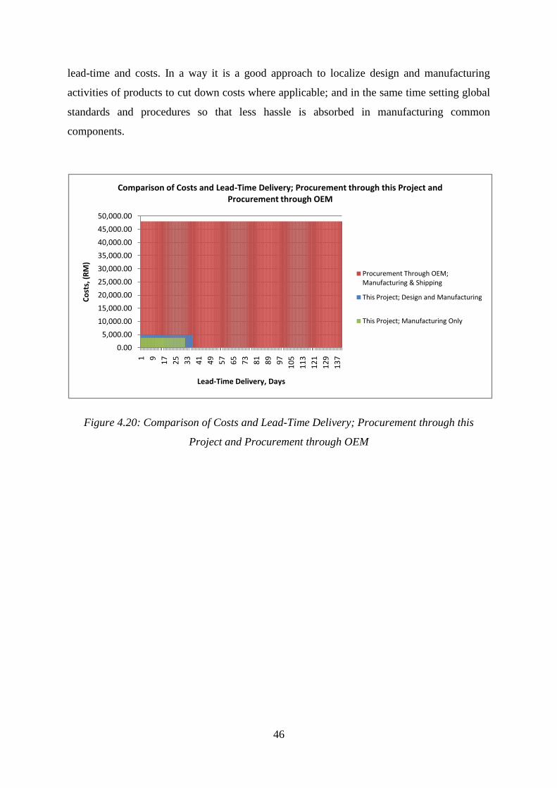
46
lead-time and costs. In a way it is a good approach to localize design and manufacturing
activities of products to cut down costs where applicable; and in the same time setting global
standards and procedures so that less hassle is absorbed in manufacturing common
components.
Figure 4.20: Comparison of Costs and Lead-Time Delivery; Procurement through this
Project and Procurement through OEM
0.00
5,000.00
10,000.00
15,000.00
20,000.00
25,000.00
30,000.00
35,000.00
40,000.00
45,000.00
50,000.00
1 9
17
25
33
41
49
57
65
73
81
89
97
10
5
11
3
12
1
12
9
13
7
Co
sts,
(R
M)
Lead-Time Delivery, Days
Comparison of Costs and Lead-Time Delivery; Procurement through this Project and Procurement through OEM
Procurement Through OEM; Manufacturing & Shipping
This Project; Design and Manufacturing
This Project; Manufacturing Only

47
5 CONCLUSIONS AND RECOMMENDATIONS
One of the major objectives of any industry is to gain monetary profit by selling its product.
In order to make sure continuous production of its product, a producer must first ensure that
its means of production is reliable.
As far as production and manufacturing industry is concerned, reliable means of production
carries the same meaning as plant reliability. In order to make sure a plant is reliable, the
operators must first guarantee the reliability and operatability of its equipments. Various
types of maintenance approaches have been studied, and when proved to be practical, have
been adopted to maintain the reliability of mechanical equipments. Nevertheless, when it
comes to purchasing replacement mechanical components, plant operators have always
regarded the OEM as the only significant source of procurement.
The issues regarding procurement of spares through OEM lie in the facts that they usually
force a considerably high lead-time delivery, aside from elevated costs. This scenario is
generally acceptable, because replacement spare purchasing is typically done prior to
equipment breakdown, where spares are available when they are needed. However, when
unexpected incidents occur, such as components' repetitive failure or breakdown of
equipment prior to spare parts delivery, procurement through OEM can no longer be accepted
as a favorable means.
This project was done with major objective of studying the alternative ways of procuring
spare parts with LESS costs and lead-time delivery. The first means of establishing the
objective is by designing a mechanical component, a centrifugal pump impeller. The data for
the pump operation is acquisited from an actual oil field, to establish the credibility of the
design. The design involved numerical design of the impeller as well as CAD modeling of the
prototype. Somehow this activity verified that mechanical equipment can be designed locally,
and in doing so the lead-time delivery and costs could be reduced, by cutting down the
shipping duration and costs.
The subsequent milestone in the project is the solid prototyping and manufacturing phase.
The virtual CAD model was translated into a solid wax model through rapid prototyping. The
RP wax model was then directly used as an expendable pattern in investment casting process
to produce solid metallic model of the impeller. Somehow this activity justifies the objective
by verifying that rapid prototyping technology could be conjoined with conventional method

48
of manufacturing mechanical components, and in doing so further reduced the lead-time
delivery and costs by establishing a more rapid and less costly approaches of procuring
spares. Nevertheless, there are some detrimental effects encountered during this procedure,
that is the defects of the investment cast product and also the fact that the surface finish of the
RP model were not highly satisfying.
The next milestone of this project is analysis of the benefit of this project in terms of costs
and lead-time delivery. The analysis somehow concluded that the procedures adopted in this
project are feasible to be used as an alternative in procuring mechanical replacement
components. The analysis also concluded that the procurement approaches illustrated in this
project were way more practical than conventional means of procurement (through OEM) in
terms of costs and lead-time delivery.
The author would like to suggest a few recommendations that the author believe will be able
to help this project yield better results. One of the major issues encountered in this project is
the surface finish quality of the RP wax model. The rapid prototyping procedure was carried
out using the technique of laser printing. This technique somehow solidifies the wax and
keeps the support materials connected, instead of loosed, with each other. After the post-
processing procedure, the surfaces that are directly attached to support materials will suffer
poor surface finish quality. The author recommends a study be conducted on ways to reduce
or eliminate this effect, most probably by experimenting with geometries of the prototyping
surfaces or by substitution of the RP raw materials.
This investment cast prototype also suffered defects due to improper methods of investment
slurry coating. The author recommends a study be carried out to establish the minimum
numbers of slurry coating on different geometries of patterns for investment casting. This
study could result in a more efficient and cost-effective process of investment casting.
For the continuation of this project, the author would like to recommend a study be carried
out to determine the quality of the final impeller produced in this project with respect to the
actual impeller of equivalent geometries and applications produced by the OEM. This study
will be able to determine whether the approaches adopted in this project are on par or not
with the impeller manufactured by OEM. If somehow the impeller were of less quality than
the one manufactured by OEM, further modifications on the materials and manufacturing
activities could be proposed and investigated.

49
Finally, most of the actual manufacturing processes to mass produce mechanical components
are through metal casting. To appreciate the importance of metal casting technology, the
author would like to propose that Universiti Teknologi PETRONAS provide a learning-scale
casting facility or foundry. By this, the students will be able to experience the actual metal
casting procedures, and researchers would not be having much trouble to experiment with
metal casting procedures, if required by their project.

50
REFERENCES
[1] Satter A. and Thakur G., 1994, Integrated Petroleum Reservoir Management A Team
Approach, Oklahoma, PennWell Books.
[2] Dec 1999, Reservoir Engineering: Augmented Recovery, http://www.spe.org/spe-
app/spe/jpt/1999/12/frontiers_res_eng_augmented.htm#, Society of Petroleum Engineers.
[3] Lobanoff, Val S., Ross, Robert R., 1992, Centrifugal Pumps: Design and Application,
Houston, TX., Gulf Publishing Company.
[4] Nelik L., 1999, Centrifugal and Rotary Pumps: Fundamental With Applications, CRC
Press LLC.
[5] Myer Kutz, 2006, Mechanical Engineers’ Handbook: Materials and Mechanical
Design, Volume 1, 3rd
Edition, John Wiley & Sons Inc.
[6] Peters M. S., Timmerhaus K. D., West R. E., 2003, Plant Design and Economics for
Chemical Engineers, McGraw Hill Professional.
[7] Karassik I. J., McGuire T., 2000, Centrifugal Pump, Second Edition, Kluwer
Academic Publishers.
[8] Jones, D. D., D. H. Vanderholm, Pumping Animal Wastes, Agricultural Engineering
Department, Perdue University, West Lafayette, Indiana.
[9] 1995, API Standard 610: Centrifugal Pumps for Petroleum, Heavy Duty Chemical,
and Gas Industry Services, 8th Edition, Washington, American Petroleum Institute.
[10] McNally, <http://www.mcnallyinstitute.com/03-html/3-10.html>, McNally Institute
Book Division.
[11] Latil M., 1980, Enhanced Oil Recovery, Institut Français du Pétrole, Paris, Editions
Technip.
[12] Tuzson J., 2000, Centrifugal Pump Design, John Wiley & Sons, Inc.
[13] McCain W.D., Jr., 1990, The Properties of Petroleum Fluids, Second Edition,
Oklahoma, PennWell Publishing Company.
[14] Gross, Grant, M., 1994, Oceanography, 6th Edition, Ohio.

51
[15] Heizer J., Render B., 2006, Operations Management, Pearson International Edition.
[16] 2008, Maintenance and Safety DLPD Notes 2, Birla Institure of Technology and
Science, Pillani, India.
[17] 2000, Statement of Work (Sow) For the Flexible Acquisition & Sustainment Tool
(Fast), Air Force Materiel Command (AFMC), Oklahoma City Air Logistics Center (OC-
ALC), Ogden Air Logistics Center (OO-ALC), Warner Robins Air Logistics Center (WR-
ALC).
[18] Walker J., 1997, “Base Stock Level Determination for “Insurance Type” Spares”,
International Journal of Quality & Reliability Management 14 (6): 569-574.
[19] Cooper, Kenneth G., 2001, Rapid Prototyping Technology Selection and Application,
New York, Marcel Dekker, Inc.
[20] Gebhardt, A., 2003, Rapid Prototyping, Munich, Carl Hanser Verlag.
[21] Chua C.K., Leong K.F., and Lim C.S., 2003, Rapid Prototyping: Principles and
Applications, World Scientific Publishing Co.
[22] Heizer J., Render B., 2006, Operations Management, Pearson International Edition.
[23] Chua C. K.,Leong K. F., 1997, Rapid Prototyping Principles and Application in
Manufacturing, John Wiley & Sons, Inc.
[24] Beeley P. R., Smart R. F., 1995, Investment Casting, The Institute of Materials.
[25] Goetsch D. L., 1991, Modern Manufacturing Processes, Delmar publishers Inc.
[26] < http://www.azom.com/details.asp?ArticleID=965>
[27] 2007, <http://www.exportbureau.com/telephone_codes/electric2.html>, Export
Bureau.
[28] 2007,
<http://www.gouldspumps.com/download_files/pump_fundamentals/gp_pf_sectb_02c.stm>,
ITT Industries, Inc.
[29] 2005, Specification Sheet: 2205 (UNS S32205/S31803): A 22Cr-3Mo Stainless Steel,
Sandmeyer Steel Company.

52
[30] ASM International, 1987, ASM Handbook: Volume 13: Corrosion, ASM
International.
[31] 2006, Waukesha 2006 Power Ratings, Waukesha Engine, Dresser Inc.
[32] 2007,
<http://www.efunda.com/materials/alloys/stainless_steels/show_stainless.cfm?ID=AISI_Typ
e_316&prop=all&Page_Title=AISI%20Type%20316>, eFunda.

53
APPENDICES
LIST OF APPENDICES
APPENDIX I: MATERIAL PROPERTIES AND DESCRIPTION, GRADE SUS. 304 54
APPENDIX II: PROJECT ACTIVITIES FLOW – GANTT CHART . . 58
APPENDIX III: EFFICIENCY OF CENTRIFUGAL PUMPS VS. SPECIFIC SPEED
CHART . . . . . . . . . . 59
APPENDIX IV: PROCEDURES OF IMPELLER NUMERICAL DESIGN . 60
APPENDIX V: COORDINATE ITERATION FOR IMPELLER END VIEW, POINT 1
THROUGH 4 . . . . . . . . . . 71
APPENDIX VI: VERIFICATION DOCUMENTS FOR SECTION 4.4 . . 73

APPENDIX I
54
Stainless Steel - Grade 304
Chemical Formula
Fe, <0.08% C, 17.5-20% Cr, 8-11% Ni, <2% Mn, <1% Si, <0.045% P, <0.03% S
Background
Grade 304 is the standard "18/8" stainless; it is the most versatile and most widely used
stainless steel, available in a wider range of products, forms and finishes than any other. It
has excellent forming and welding characteristics. The balanced austenitic structure of Grade
304 enables it to be severely deep drawn without intermediate annealing, which has made this
grade dominant in the manufacture of drawn stainless parts such as sinks, hollow-ware and
saucepans. For these applications it is common to use special "304DDQ" (Deep Drawing
Quality) variants. Grade 304 is readily brake or roll formed into a variety of components for
applications in the industrial, architectural, and transportation fields. Grade 304 also has
outstanding welding characteristics. Post-weld annealing is not required when welding thin
sections.
Grade 304L, the low carbon version of 304, does not require post-weld annealing and so is
extensively used in heavy gauge components (over about 6mm). Grade 304H with its higher
carbon content finds application at elevated temperatures. The austenitic structure also gives
these grades excellent toughness, even down to cryogenic temperatures.
Key Properties
These properties are specified for flat rolled product (plate, sheet and coil) in ASTM
A240/A240M. Similar but not necessarily identical properties are specified for other products
such as pipe and bar in their respective specifications.
Composition
Typical compositional ranges for grade 304 stainless steels are given in table 1.
Table 1. Composition ranges for 304 grade stainless steel
Grade C Mn Si P S Cr Mo Ni N
304
min.
max.
-
0.08
-
2.0
-
0.75
-
0.045
-
0.030
18.0
20.0
-
8.0
10.5
-
0.10
304L
min.
max.
-
0.030
-
2.0
-
0.75
-
0.045
-
0.030
18.0
20.0
-
8.0
12.0
-
0.10
304H
min.
max.
0.04
0.10
-
2.0
-
0.75
-
0.045
-
0.030
18.0
20.0
-
8.0
10.5
-

APPENDIX I
55
Mechanical Properties
Typical mechanical properties for grade 304 stainless steels are given in table 2.
Table 2. Mechanical properties of 304 grade stainless steel
Grade
Tensile
Strength (MPa)
min
Yield Strength
0.2% Proof
(MPa) min
Elongation (% in
50mm) min
Hardness
Rockwell B
(HR B) max
Brinell (HB)
max
304 515 205 40 92 201
304L 485 170 40 92 201
304H 515 205 40 92 201
304H also has a requirement for a grain size of ASTM No 7 or coarser.
Physical Properties
Typical physical properties for annealed grade 304 stainless steels are given in table 3.
Table 3. Physical properties of 304 grade stainless steel in the annealed condition
Grade Density
(kg/m3)
Elastic
Modulus
(GPa)
Mean Coefficient of Thermal
Expansion (mm/m/°C)
Thermal
Conductivity
(W/m.K)
Specific
Heat 0-
100°C
(J/kg.K)
Electrical
Resistivity
(nW.m) 0-100°C 0-315°C 0-538°C at 100°C at 500°C
304/L/H 8000 193 17.2 17.8 18.4 16.2 21.5 500 720
Grade Specification Comparison
Approximate grade comparisons for 304 stainless steels are given in table 4.
Table 4. Grade specifications for 304 grade stainless steel
Grade UNS No Old British Euronorm Swedish
SS
Japanese
JIS BS En No Name
304 S30400 304S31 58E 1.4301 X5CrNi18-10 2332 SUS 304
304L S30403 304S11 - 1.4306 X2CrNi19-11 2352 SUS 304L
304H S30409 304S51 - 1.4948 X6CrNi18-11 - -
These comparisons are approximate only. The list is intended as a comparison of functionally similar materials
not as a schedule of contractual equivalents. If exact equivalents are needed original specifications must be
consulted.
Possible Alternative Grades
Possible alternative grades to grade 304 stainless steels are given in table 5.
Table 5. Possible alternative grades to 304 grade stainless steel
Grade Why it might be chosen instead of 304
301L A higher work hardening rate grade is required for certain roll formed or stretch formed components.
302HQ Lower work hardening rate is needed for cold forging of screws, bolts and rivets.
303 Higher machinability needed, and the lower corrosion resistance, formability and weldability are
acceptable.
316 Higher resistance to pitting and crevice corrosion is required, in chloride environments

APPENDIX I
56
321 Better resistance to temperatures of around 600-900°C is needed…321 has higher hot strength.
3CR12 A lower cost is required, and the reduced corrosion resistance and resulting discolouration are
acceptable.
430 A lower cost is required, and the reduced corrosion resistance and fabrication characteristics are
acceptable.
Corrosion Resistance
Excellent in a wide range of atmospheric environments and many corrosive media. Subject to
pitting and crevice corrosion in warm chloride environments, and to stress corrosion cracking
above about 60°C. Considered resistant to potable water with up to about 200mg/L chlorides
at ambient temperatures, reducing to about 150mg/L at 60°C.
Heat Resistance
Good oxidation resistance in intermittent service to 870°C and in continuous service to
925°C. Continuous use of 304 in the 425-860°C range is not recommended if subsequent
aqueous corrosion resistance is important. Grade 304L is more resistant to carbide
precipitation and can be heated into the above temperature range.
Grade 304H has higher strength at elevated temperatures so is often used for structural and
pressure-containing applications at temperatures above about 500°C and up to about 800°C.
304H will become sensitised in the temperature range of 425-860°C; this is not a problem for
high temperature applications, but will result in reduced aqueous corrosion resistance.
Heat Treatment
Solution Treatment (Annealing) - Heat to 1010-1120°C and cool rapidly. These grades
cannot be hardened by thermal treatment.
Welding
Excellent weldability by all standard fusion methods, both with and without filler metals. AS
1554.6 pre-qualifies welding of 304 with Grade 308 and 304L with 308L rods or electrodes
(and with their high silicon equivalents). Heavy welded sections in Grade 304 may require
post-weld annealing for maximum corrosion resistance. This is not required for Grade 304L.
Grade 321 may also be used as an alternative to 304 if heavy section welding is required and
post-weld heat treatment is not possible.
Machining
A "Ugima" improved machinability version of grade 304 is available in bar products.
"Ugima" machines significantly better than standard 304 or 304L, giving higher machining
rates and lower tool wear in many operations.
Dual Certification
It is common for 304 and 304L to be stocked in "Dual Certified" form, particularly in plate
and pipe. These items have chemical and mechanical properties complying with both 304 and
304L specifications. Such dual certified product does not meet 304H specifications and may
be unacceptable for high temperature applications.

APPENDIX I
57
Applications
Typical applications include:
Food processing equipment, particularly in beer brewing, milk processing & wine
making.
Kitchen benches, sinks, troughs, equipment and appliances
Architectural panelling, railings & trim
Chemical containers, including for transport
Heat Exchangers
Woven or welded screens for mining, quarrying & water filtration
Threaded fasteners
Springs
Source: Atlas Steels Australia
For more information on this source please visit Atlas Steels Australia.

APPENDIX II
58
Desig
n a
nd
Pro
toty
pin
g o
f Cen
trifuga
l Pu
mp
Imp
eller to b
e used
as W
ater In
jection
Pu
mp
for H
yd
roca
rbon
Artificia
l Lift
Pro
ject Activ
ities Flo
w –
Gan
tt Chart
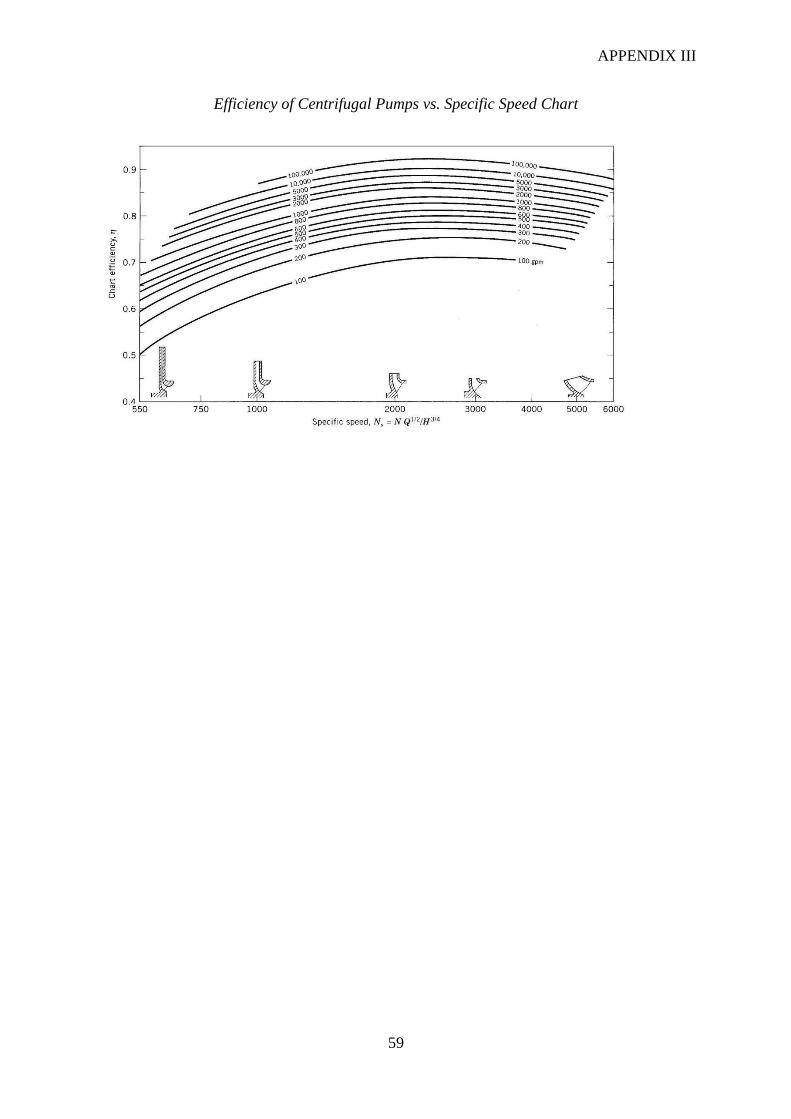
APPENDIX III
59
Efficiency of Centrifugal Pumps vs. Specific Speed Chart

APPENDIX IV
60
APP IV: PROCEDURES OF IMPELLER NUMERICAL DESIGN
APP IV.1 Selection of Vane Number and Discharge Angle
Figure APP IV.1: Vane Number Selection Graph
From Vane Number Selection Graph (Figure APP IV.1) [3], for Shutoff Head – BEP Head
percent rise of 20% and specific speed of 1085.592, the suitable number of vanes, Z, and
discharge angle, β2, is:
Z = 6;
β2 = 25°
APP IV.2 Calculation of Impeller Diameter
Figure APP IV.2: Head Constant Graph
From Head Constant Graph (Figure APP IV.2) [3], the corresponding value of Head
Constant, Ku, for this impeller is:
Ku = 1.022

APPENDIX IV
61
The impeller diameter, D2, is therefore:
APP IV.3 Calculation of Impeller Width
Figure APP IV.3: KM2 Capacity Constant Graph
From KM2 Capacity Constant Graph (Figure APP IV.3) [3], the corresponding value of KM2 is:
KM2 = 0.092 ;
;
KM2 = Capacity Constant
CM2 = Radial Velocity at Impeller Discharge
g = gravitational acceleration constant, 32.174 ft/s2
b2 = impeller width in inches
Su = Vane thickness at D2. Assumed to be 0.5 inch. Will be confirmed during vane development. This
calculation repeated if necessary,

APPENDIX IV
62
APP IV.4 Determination of Eye Diameter
Figure APP IV.4: Impeller Eye Diameter / Impeller Diameter Ratio Graph
From Impeller Eye Diameter / Impeller Diameter Ratio Graph (Figure APP IV.4) [3];
APP IV.5 Shaft Sizing
To determine shaft diameter for this particular application, the author would have to first
select the suitable material for seawater pumping purposes. Based on material selection chart
provided by Goulds Pumps, the suitable and economical material would be alloy 2205 duplex
stainless steel [28]. This material combines high strength and high corrosion resistance to
produce high corrosion fatigue strength, and therefore can be subjected to aggressively
corrosive environment such as handling seawater [29]. Alloy steels exhibits mechanical
properties superior to that of ordinary carbon steel with respect to hardenability, toughness, or
reduction of environmental degradation under specific service conditions [30].
As suggested by Karassik et al., typical torsional stress for alloy steel is [7]:
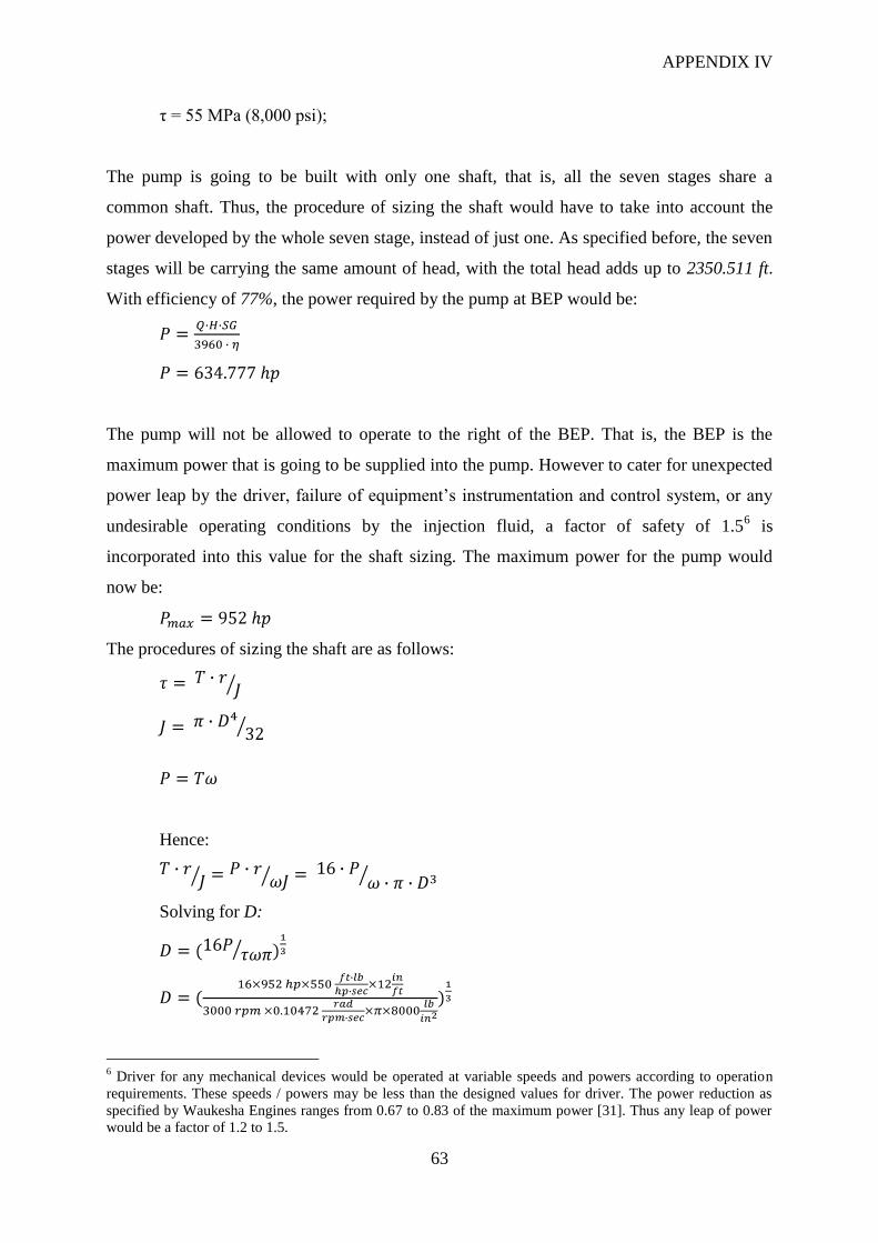
APPENDIX IV
63
τ = 55 MPa (8,000 psi);
The pump is going to be built with only one shaft, that is, all the seven stages share a
common shaft. Thus, the procedure of sizing the shaft would have to take into account the
power developed by the whole seven stage, instead of just one. As specified before, the seven
stages will be carrying the same amount of head, with the total head adds up to 2350.511 ft.
With efficiency of 77%, the power required by the pump at BEP would be:
The pump will not be allowed to operate to the right of the BEP. That is, the BEP is the
maximum power that is going to be supplied into the pump. However to cater for unexpected
power leap by the driver, failure of equipment’s instrumentation and control system, or any
undesirable operating conditions by the injection fluid, a factor of safety of 1.56 is
incorporated into this value for the shaft sizing. The maximum power for the pump would
now be:
The procedures of sizing the shaft are as follows:
Hence:
Solving for D:
6 Driver for any mechanical devices would be operated at variable speeds and powers according to operation
requirements. These speeds / powers may be less than the designed values for driver. The power reduction as
specified by Waukesha Engines ranges from 0.67 to 0.83 of the maximum power [31]. Thus any leap of power
would be a factor of 1.2 to 1.5.

APPENDIX IV
64
For design, the diameter is round up to nearest in increment:
T = torque in in·lb
r = shaft radius in in
J = polar moment of inertia of the cross-section of the shaft
D = shaft diameter in in
ω = shaft rotational speed in rad/s
P = power input into the pump, in lb·in/sec
APP IV.6 Key Sizing
According to ANSI-B17.1, the general practice is to use key size of height (W) of one-fourth
of the shaft diameter [3]:
For the design of impeller key, the author selected alloy 316 austenitic stainless steel for the
material. The reasons why this material is used are:
i. Similar to the shaft material, stainless steel 316 provides extraordinary range of
corrosion resistance.
ii. The impeller key is going to be replaced more frequently during maintenance and
services rather than the impellers and shaft itself, thus stainless steel 316 is the better
choice than alloy 2205 based on:
a. Most commonly used corrosion resistant alloy (widely available) [5].
b. Falls in moderately price range [5].
The key design is commenced with calculation of torque transmitted:
The force on the key is:
Key material data of the key:
Material: stainless steel 316

APPENDIX IV
65
Yield Strength: 205 MPa (29732.7 psi) [5]
Poisson’s Ratio: 0.27 [32]
Shear Strength: 11705.787 psi
Safety Factor: 1.5 [3]
Design Stress: 7803.858 psi
Shear Stress Equation:
τ1 = design stress in psi
A1 = key area in in2
L = key length in in
W = key width / height in in
The key is illustrated in Figure APP IV.5:
Figure APP IV.5: Illustration of Impeller-Shaft Key (all units in inches)
APP IV.7 Shaft Sleeve Sizing
Shaft sleeve is incorporated in this design with a specific aim to axially locate the impeller on
the shaft:
Calculation of axial force:
F = Force, in lb
Pdis = Discharge pressure of the whole multistage pump, in psi
Obviously the actual axial force acting on the impeller is less than this value, due to the facts
that:
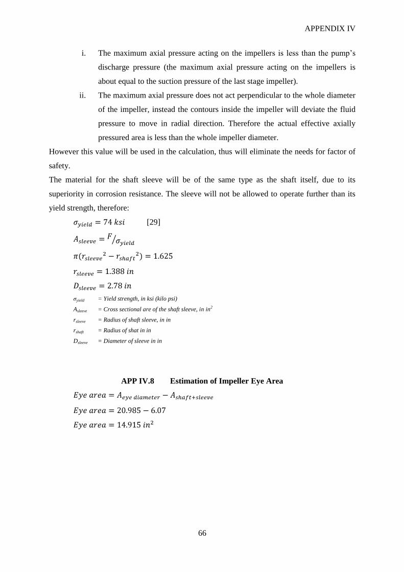
APPENDIX IV
66
i. The maximum axial pressure acting on the impellers is less than the pump’s
discharge pressure (the maximum axial pressure acting on the impellers is
about equal to the suction pressure of the last stage impeller).
ii. The maximum axial pressure does not act perpendicular to the whole diameter
of the impeller, instead the contours inside the impeller will deviate the fluid
pressure to move in radial direction. Therefore the actual effective axially
pressured area is less than the whole impeller diameter.
However this value will be used in the calculation, thus will eliminate the needs for factor of
safety.
The material for the shaft sleeve will be of the same type as the shaft itself, due to its
superiority in corrosion resistance. The sleeve will not be allowed to operate further than its
yield strength, therefore:
[29]
σyield = Yield strength, in ksi (kilo psi)
Asleeve = Cross sectional are of the shaft sleeve, in in2
rsleeve = Radius of shaft sleeve, in in
rshaft = Radius of shat in in
Dsleeve = Diameter of sleeve in in
APP IV.8 Estimation of Impeller Eye Area

APPENDIX IV
67
Figure APP IV.6: NPSHR Prediction Chart

APPENDIX IV
68
APP IV.9 Estimation of Net Positive Suction Head Required (NPSHR)
From NPSHR Prediction Chart (Figure APP IV.6) [3];
Cm1 = average meridianal velocity at blade inlet in ft/sec
U2 = impeller peripheral velocity in ft/sec
Nss = suction specific speed
APP IV.10 Determination of Volute Diameter
Figure APP IV.6: Volute Velocity Constant Graph
Although this project only focuses on designing the impeller, volute design must also be
covered to consider any limitation on the pump casing.
From Volute Velocity Constant Graph (Figure APP IV.6) [3];

APPENDIX IV
69
K3 = volute velocity constant
Ag = volute throat area in in2
This value of Ag is final for the type of pump designed in this project, which is single volute
centrifugal pump.
In establishing the volute width, the author took into account the needs to accommodate
impellers of different diameter and width for future modifications / efficiency upgrade of the
pump. The distance from impeller shrouds to casing should be sufficient enough to allow any
manufacturing accuracies yet maintain a minimum end play.
According to values published by Stepanoff in Table APP IV.1 [3]:
Table APP IV.1: Guidelines for Volute Width
Specific Speed, Ns Volute Width, b3
<1000 2.0 b2
1000-3000 1.75 b2
>3000 1.6 b2
APPENDIX IV
70
Careful consideration must be taken in designing the cutwater diameter7 in order to prevent
noise, pulsation, and vibration [3]. The vibration will be multiplicated at vane pass
frequency8. According to guidelines for cutwater diameter table, Table APP IV.2 [3]:
Table APP IV.2: Guidelines for Cutwater Diameter
Specific Speed, Ns Cutwater Diameter, D3
600-1000 D2 1.05
1000-1500 D2 1.06
1500-2500 D2 1.07
2500-4000 D2 1.09
7 Cutwater diameter is the gap between the impeller diameter and volute lip.
8 Vane pass frequency vibration is the vibration generated at speed of (no. of blades x rotating speed of
equipment). This vibration is inherent in pumps, compressors, and blowers.
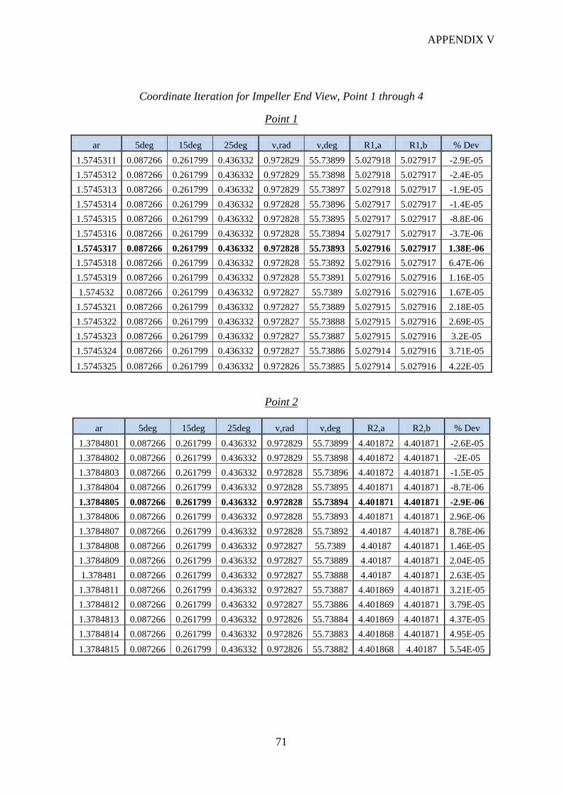
APPENDIX V
71
Coordinate Iteration for Impeller End View, Point 1 through 4
Point 1
ar 5deg 15deg 25deg v,rad v,deg R1,a R1,b % Dev
1.5745311 0.087266 0.261799 0.436332 0.972829 55.73899 5.027918 5.027917 -2.9E-05
1.5745312 0.087266 0.261799 0.436332 0.972829 55.73898 5.027918 5.027917 -2.4E-05
1.5745313 0.087266 0.261799 0.436332 0.972829 55.73897 5.027918 5.027917 -1.9E-05
1.5745314 0.087266 0.261799 0.436332 0.972828 55.73896 5.027917 5.027917 -1.4E-05
1.5745315 0.087266 0.261799 0.436332 0.972828 55.73895 5.027917 5.027917 -8.8E-06
1.5745316 0.087266 0.261799 0.436332 0.972828 55.73894 5.027917 5.027917 -3.7E-06
1.5745317 0.087266 0.261799 0.436332 0.972828 55.73893 5.027916 5.027917 1.38E-06
1.5745318 0.087266 0.261799 0.436332 0.972828 55.73892 5.027916 5.027917 6.47E-06
1.5745319 0.087266 0.261799 0.436332 0.972828 55.73891 5.027916 5.027916 1.16E-05
1.574532 0.087266 0.261799 0.436332 0.972827 55.7389 5.027916 5.027916 1.67E-05
1.5745321 0.087266 0.261799 0.436332 0.972827 55.73889 5.027915 5.027916 2.18E-05
1.5745322 0.087266 0.261799 0.436332 0.972827 55.73888 5.027915 5.027916 2.69E-05
1.5745323 0.087266 0.261799 0.436332 0.972827 55.73887 5.027915 5.027916 3.2E-05
1.5745324 0.087266 0.261799 0.436332 0.972827 55.73886 5.027914 5.027916 3.71E-05
1.5745325 0.087266 0.261799 0.436332 0.972826 55.73885 5.027914 5.027916 4.22E-05
Point 2
ar 5deg 15deg 25deg v,rad v,deg R2,a R2,b % Dev
1.3784801 0.087266 0.261799 0.436332 0.972829 55.73899 4.401872 4.401871 -2.6E-05
1.3784802 0.087266 0.261799 0.436332 0.972829 55.73898 4.401872 4.401871 -2E-05
1.3784803 0.087266 0.261799 0.436332 0.972828 55.73896 4.401872 4.401871 -1.5E-05
1.3784804 0.087266 0.261799 0.436332 0.972828 55.73895 4.401871 4.401871 -8.7E-06
1.3784805 0.087266 0.261799 0.436332 0.972828 55.73894 4.401871 4.401871 -2.9E-06
1.3784806 0.087266 0.261799 0.436332 0.972828 55.73893 4.401871 4.401871 2.96E-06
1.3784807 0.087266 0.261799 0.436332 0.972828 55.73892 4.40187 4.401871 8.78E-06
1.3784808 0.087266 0.261799 0.436332 0.972827 55.7389 4.40187 4.401871 1.46E-05
1.3784809 0.087266 0.261799 0.436332 0.972827 55.73889 4.40187 4.401871 2.04E-05
1.378481 0.087266 0.261799 0.436332 0.972827 55.73888 4.40187 4.401871 2.63E-05
1.3784811 0.087266 0.261799 0.436332 0.972827 55.73887 4.401869 4.401871 3.21E-05
1.3784812 0.087266 0.261799 0.436332 0.972827 55.73886 4.401869 4.401871 3.79E-05
1.3784813 0.087266 0.261799 0.436332 0.972826 55.73884 4.401869 4.401871 4.37E-05
1.3784814 0.087266 0.261799 0.436332 0.972826 55.73883 4.401868 4.401871 4.95E-05
1.3784815 0.087266 0.261799 0.436332 0.972826 55.73882 4.401868 4.40187 5.54E-05

APPENDIX V
72
Point 3
ar 5deg 15deg 25deg v,rad v,deg R3,a R3,b % Dev
1.20157 0.087266 0.261799 0.436332 0.97284 55.73961 3.836977 3.836965 -0.00033
1.201571 0.087266 0.261799 0.436332 0.972837 55.73948 3.836974 3.836964 -0.00027
1.201572 0.087266 0.261799 0.436332 0.972835 55.73934 3.836971 3.836964 -0.0002
1.201573 0.087266 0.261799 0.436332 0.972833 55.7392 3.836968 3.836963 -0.00013
1.201574 0.087266 0.261799 0.436332 0.97283 55.73907 3.836965 3.836963 -6.5E-05
1.201575 0.087266 0.261799 0.436332 0.972828 55.73893 3.836962 3.836962 2.12E-06
1.201576 0.087266 0.261799 0.436332 0.972825 55.73879 3.836959 3.836962 6.89E-05
1.201577 0.087266 0.261799 0.436332 0.972823 55.73866 3.836956 3.836961 0.000136
1.201578 0.087266 0.261799 0.436332 0.972821 55.73852 3.836953 3.836961 0.000203
1.201579 0.087266 0.261799 0.436332 0.972818 55.73838 3.83695 3.83696 0.000269
1.20158 0.087266 0.261799 0.436332 0.972816 55.73825 3.836947 3.83696 0.000336
1.201581 0.087266 0.261799 0.436332 0.972814 55.73811 3.836944 3.836959 0.000403
1.201582 0.087266 0.261799 0.436332 0.972811 55.73797 3.836941 3.836959 0.00047
1.201583 0.087266 0.261799 0.436332 0.972809 55.73784 3.836938 3.836959 0.000537
1.201584 0.087266 0.261799 0.436332 0.972806 55.7377 3.836935 3.836958 0.000603
Point 4
ar 5deg 15deg 25deg v,rad v,deg R4,a R4,b % Dev
1.04737 0.087266 0.261799 0.436332 0.972834 55.7393 3.344558 3.344552 -0.00018
1.047371 0.087266 0.261799 0.436332 0.972832 55.73914 3.344555 3.344551 -0.0001
1.047372 0.087266 0.261799 0.436332 0.972829 55.73899 3.344552 3.344551 -2.6E-05
1.047373 0.087266 0.261799 0.436332 0.972826 55.73883 3.344548 3.34455 5.11E-05
1.047374 0.087266 0.261799 0.436332 0.972823 55.73867 3.344545 3.34455 0.000128
1.047375 0.087266 0.261799 0.436332 0.972821 55.73852 3.344542 3.344549 0.000204
1.047376 0.087266 0.261799 0.436332 0.972818 55.73836 3.344539 3.344549 0.000281
1.047377 0.087266 0.261799 0.436332 0.972815 55.7382 3.344536 3.344548 0.000358
1.047378 0.087266 0.261799 0.436332 0.972812 55.73805 3.344533 3.344548 0.000434
1.047379 0.087266 0.261799 0.436332 0.97281 55.73789 3.34453 3.344547 0.000511
1.04738 0.087266 0.261799 0.436332 0.972807 55.73773 3.344527 3.344547 0.000588
1.047381 0.087266 0.261799 0.436332 0.972804 55.73758 3.344524 3.344546 0.000664
1.047382 0.087266 0.261799 0.436332 0.972802 55.73742 3.344521 3.344546 0.000741
1.047383 0.087266 0.261799 0.436332 0.972799 55.73726 3.344518 3.344546 0.000818
1.047384 0.087266 0.261799 0.436332 0.972796 55.73711 3.344515 3.344545 0.000894

APPENDIX VI
73
mohd radzi mohd anua <[email protected]>
Request for Quotation 1 messages
[email protected] <[email protected]> Mon, Mar 3, 2008 at 2:46 PM Reply-To: [email protected]
To: mohd radzi mohd anua <[email protected]>
> dear Radzi,...
Thank you for your interest in our process , I am pleased to quote our
final price confirmation as follow:
Item Price(Rm)/pcs material
Validity
1. Impeller casting Rm45.00 Sus 304. 1 Month
We trust the above quotetion is competitive and if you have any
queries,please do not hesitate to contact us and shell be looking forward
to receive order confirmation in due couse.
Thank & regards
hazri [Quoted text hidden]

APPENDIX VI
74
mohd radzi mohd anua <[email protected]>
Enquiry on pump impeller approximate lead-time and
cost 2 messages
mohd radzi mohd anua <[email protected]> Thu, Apr 3, 2008 at 2:02 PM To: [email protected]
Dear Mr. Michael Tan,
My name is Mohd Radzi from PCSB SKO, regarding our phone conversation just now, I was required to
find out rough estimates of these information:
Item: Pump Impeller
Size: 12 inch (diameter)
Approximate price:
Lead-time delivery:
Thank you in advance for your kind consideration.
Regards,
Radzi Anua
[email protected] <[email protected]> Thu, Apr 3, 2008 at 2:51 PM To: mohd radzi mohd anua <[email protected]>
Estimated price US$15k and 16 - 24 weeks delivery time.
-------------------------------
NOTICE: The information contained in this e-mail, and attachment(s) thereto, is confidential and may
contain attorney - client privileged communications. If you are not the intended recipient, you are hereby
notified that any dissemination, distribution, or copying of this communication is strictly prohibited. If you
have received this communication in error, please notify the sender immediately and delete the e-mail from
your computer system without retaining any copies. Thank you.
[Quoted text hidden]