Publication 25182 (Revision R, 8/2015 ... - Woodward, Inc. · PDF file505 Steam Turbine...
78
Publication 25182 (Revision R, 8/2015) RESTRICTED—NOT FOR GENERAL DISTRIBUTION Energy Controls Standard Products Product Information Updated to 7 July 2015
Transcript of Publication 25182 (Revision R, 8/2015 ... - Woodward, Inc. · PDF file505 Steam Turbine...

Publication 25182(Revision R, 8/2015)
RESTRICTED—NOT FOR GENERAL DISTRIBUTION
Energy Controls Standard Products Product Information
Updated to 7 July 2015


Contents 1—All Electric Governors ............................................................................................................... 5 1. ProAct ISC (Integrated Speed Control) Actuators/Throttle Bodies ................................... 5 2. ProAct Accessories .......................................................................................................... 5 3. Flo-Tech Speed Controls/Actuators/Throttle Bodies ........................................................ 5 4. EPG .................................................................................................................................. 6 5. R-Series Electric Actuators ............................................................................................. 76 2—APECS Products ........................................................................................................................ 8 1. APECS Linear Actuators .................................................................................................. 8 2. APECS Rotary Actuators .................................................................................................. 9 3. APECS Controllers ......................................................................................................... 11 4. APECS Speed Switches and Sensors ........................................................................... 13 5. APECS Accessories ....................................................................................................... 15 3—Electronic Controls .................................................................................................................. 16 1. 2301A Controls ............................................................................................................... 16 2. 2301E Electronic Load Sharing and Speed Controls ..................................................... 16 3. 2300E Electronic Load Sharing and Speed Controls ..................................................... 16 4. 723 Controls ................................................................................................................... 16 5. 723PLUS Controls .......................................................................................................... 17 6. 828 Control (723PLUS) Hardware Platform for Distributors ........................................... 17 7. Custom Control Platforms (AtlasSC / Atlas-II) ................................................................ 17 8. Engine System Custom Controls (733, 766, In-Pulse 2, ECM3) .................................... 18 4—Turbine Controls and Associated Devices ............................................................................ 19 1. 2301E-ST Steam Turbine Controls ................................................................................ 19 2. Peak 150 Steam Turbine Controls ................................................................................. 19 3. 505 Steam Turbine Controls ........................................................................................... 19 4. 5009FT Steam Turbine Controls .................................................................................... 20 5. Standard MicroNet Turbine Control Kits ......................................................................... 20 6. GTC Gas Turbine Controls ............................................................................................. 20 7. Servo Position Controllers (replace Digital Remote Final Drivers) ................................. 20 8. ProTech Overspeed Protection Devices ........................................................................ 21 9. MicroNet System Modules, Cables, & Accessories ........................................................ 22 10. DVP Digital Valve Positioner .......................................................................................... 30 11. Magnetic Pickups ........................................................................................................... 31 12. Active Proximity Probes.................................................................................................. 31 5—Software Licenses ................................................................................................................... 32 6—Power Generation Products .................................................................................................... 37 1. easYgen Stand-alone Genset Controls .......................................................................... 37 2. easYgen Paralleling Genset Controls ............................................................................. 38 3. EGCP-2 Generator Controls ........................................................................................... 42 4. Switchgear Controls ....................................................................................................... 43 5. Synchronizers ................................................................................................................. 44 6. Load Share Controls ...................................................................................................... 45 7. Digital Multi-Function Relays .......................................................................................... 46 8. Expansion Modules ........................................................................................................ 47 9. Accessories and Spare Parts ......................................................................................... 47 7—Power Distribution Products ................................................................................................... 49 1. HighPROTEC Ordering Code ......................................................................................... 49 2. HighPROTEC Services .................................................................................................. 58 3. HighPROTEC Accessories ............................................................................................. 58 Woodward reserves the right to update any portion of this publication at any time. Information provided by Woodward is believed to be correct and reliable. However, no responsibility is assumed by Woodward unless otherwise expressly undertaken.
Manual 25182 Copyright © Woodward 1998–2015
All Rights Reserved

Energy Controls Product Information Manual 25182
4 Woodward
Contents 8—Electro-Hydraulic Governors & Actuators ............................................................................. 59 1. TG Turbine Governors ................................................................................................... 59 2. TGE Turbine Actuators .................................................................................................. 60 3. VariStroke Actuators ...................................................................................................... 61 4. Servo Boosters .............................................................................................................. 69 5. CPC Current-to-Pressure Converter .............................................................................. 69 6. EM Electric Actuators ..................................................................................................... 69 7. TM Actuators (Linear) .................................................................................................... 69 8. Turbine Shutdown Trip Block Assemblies ...................................................................... 69 9—Ignition Products ..................................................................................................................... 70 1. Coils ............................................................................................................................... 70 2. Shielded Harnesses ....................................................................................................... 70 3. Ignition Controllers ......................................................................................................... 70 10—L-Series Actuators and Integrated Speed Controls ............................................................ 71 1. L-Series Speed Control–Actuator Only .......................................................................... 71 2. L-Series Speed Control–Actuator with ITB..................................................................... 71 3. L-Series Process Control ITB (AFR Control) .................................................................. 71 4. L-Series Speed Control–Actuator with ITB & Venturi Mixer (MAS) ................................ 71 5. L-Series Diesel Engine Applications .............................................................................. 71 6. L-Series Speed Control with ITB & Trim Valve .............................................................. 71 7. L-Series Positioner with ITB ........................................................................................... 72 8. L-Series Accessories ..................................................................................................... 72 11—F-Series Actuators and Actuator with ITB ........................................................................... 73 1. F-Series Positioners ....................................................................................................... 73 2. Accessories .................................................................................................................... 73 12—R-Series Actuators ................................................................................................................ 73 13—TecJet Fuel Control Valves ................................................................................................... 73 14—Gas Turbine Valves ............................................................................................................... 74 1. GS6 Gas Fuel Valve Actuator w/ On-board Driver ......................................................... 74 2. GS16 Gas Fuel Valve Actuator w/ On-board Driver ....................................................... 74 3. GSOV25HT Gas Fuel Shutoff Valve .............................................................................. 74 4. LQ6 Liquid Fuel Valve Actuator w/ On-board Driver ...................................................... 74 5. LQ25 Standard Valves ................................................................................................... 74 6. LSOV25 Liquid Fuel Shutoff Valve ................................................................................. 74 7. Electric Actuator/Driver .................................................................................................. 74 15—Air/Fuel Ratio Controls.......................................................................................................... 75 1. E3 (All Encompassing Engine and Emission Control) .................................................... 75 2. Accessories .................................................................................................................... 75 16—Electronic Accessories ......................................................................................................... 76 1. Miscellaneous Accessories ............................................................................................ 76 2. Potentiometers ............................................................................................................... 76 3. Digital Reference Units .................................................................................................. 76 4. PM Motor Controls ......................................................................................................... 76 5. Swift Driver ..................................................................................................................... 76 17—Mechanical-Hydraulic Controls ............................................................................................ 77 18—Woodward Authorized Facilities .......................................................................................... 77 19—Repair and Remanufacturing Services ................................................................................ 77
Manual 25182 Energy Controls Product Information
Woodward 5
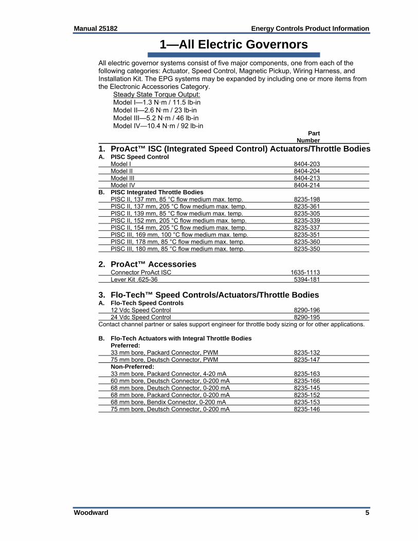
1—All Electric Governors All electric governor systems consist of five major components, one from each of the following categories: Actuator, Speed Control, Magnetic Pickup, Wiring Harness, and Installation Kit. The EPG systems may be expanded by including one or more items from the Electronic Accessories Category. Steady State Torque Output: Model I—1.3 N·m / 11.5 lb-in Model II—2.6 N·m / 23 lb-in Model III—5.2 N·m / 46 lb-in Model IV—10.4 N·m / 92 lb-in Part Number
1. ProAct™ ISC (Integrated Speed Control) Actuators/Throttle Bodies A. PISC Speed Control Model I 8404-203 Model II 8404-204 Model III 8404-213 Model IV 8404-214 B. PISC Integrated Throttle Bodies PISC II, 137 mm, 85 °C flow medium max. temp. 8235-198 PISC II, 137 mm, 205 °C flow medium max. temp. 8235-361 PISC II, 139 mm, 85 °C flow medium max. temp. 8235-305 PISC II, 152 mm, 205 °C flow medium max. temp. 8235-339 PISC II, 154 mm, 205 °C flow medium max. temp. 8235-337 PISC III, 169 mm, 100 °C flow medium max. temp. 8235-351 PISC III, 178 mm, 85 °C flow medium max. temp. 8235-360 PISC III, 180 mm, 85 °C flow medium max. temp. 8235-350
2. ProAct™ Accessories Connector ProAct ISC 1635-1113 Lever Kit .625-36 5394-181
3. Flo-Tech™ Speed Controls/Actuators/Throttle Bodies A. Flo-Tech Speed Controls 12 Vdc Speed Control 8290-196 24 Vdc Speed Control 8290-195 Contact channel partner or sales support engineer for throttle body sizing or for other applications. B. Flo-Tech Actuators with Integral Throttle Bodies Preferred: 33 mm bore, Packard Connector, PWM 8235-132 75 mm bore, Deutsch Connector, PWM 8235-147 Non-Preferred: 33 mm bore, Packard Connector, 4-20 mA 8235-163 60 mm bore, Deutsch Connector, 0-200 mA 8235-166 68 mm bore, Deutsch Connector, 0-200 mA 8235-145 68 mm bore, Packard Connector, 0-200 mA 8235-152 68 mm bore, Bendix Connector, 0-200 mA 8235-153 75 mm bore, Deutsch Connector, 0-200 mA 8235-146
Energy Controls Product Information Manual 25182
6 Woodward
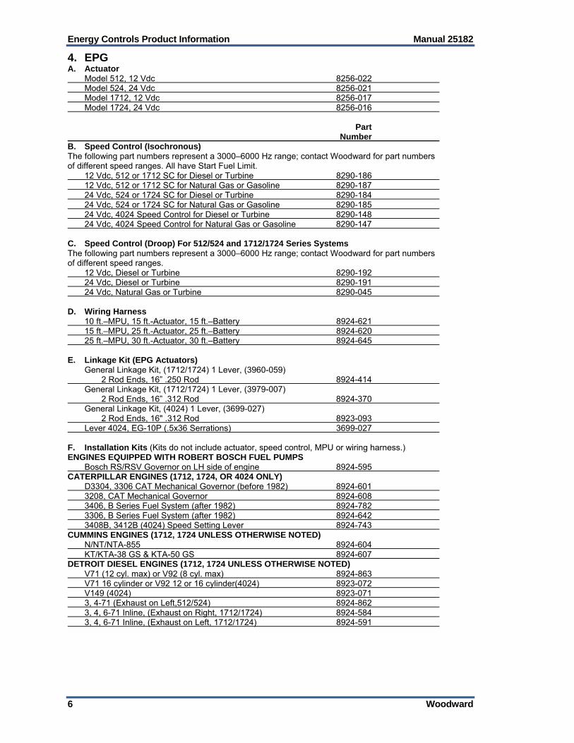
4. EPG A. Actuator Model 512, 12 Vdc 8256-022 Model 524, 24 Vdc 8256-021 Model 1712, 12 Vdc 8256-017 Model 1724, 24 Vdc 8256-016 Part Number B. Speed Control (Isochronous) The following part numbers represent a 3000–6000 Hz range; contact Woodward for part numbers of different speed ranges. All have Start Fuel Limit. 12 Vdc, 512 or 1712 SC for Diesel or Turbine 8290-186 12 Vdc, 512 or 1712 SC for Natural Gas or Gasoline 8290-187 24 Vdc, 524 or 1724 SC for Diesel or Turbine 8290-184 24 Vdc, 524 or 1724 SC for Natural Gas or Gasoline 8290-185 24 Vdc, 4024 Speed Control for Diesel or Turbine 8290-148 24 Vdc, 4024 Speed Control for Natural Gas or Gasoline 8290-147 C. Speed Control (Droop) For 512/524 and 1712/1724 Series Systems The following part numbers represent a 3000–6000 Hz range; contact Woodward for part numbers of different speed ranges. 12 Vdc, Diesel or Turbine 8290-192 24 Vdc, Diesel or Turbine 8290-191 24 Vdc, Natural Gas or Turbine 8290-045 D. Wiring Harness 10 ft.–MPU, 15 ft.-Actuator, 15 ft.–Battery 8924-621 15 ft.–MPU, 25 ft.-Actuator, 25 ft.–Battery 8924-620 25 ft.–MPU, 30 ft.-Actuator, 30 ft.–Battery 8924-645 E. Linkage Kit (EPG Actuators) General Linkage Kit, (1712/1724) 1 Lever, (3960-059) 2 Rod Ends, 16” .250 Rod 8924-414 General Linkage Kit, (1712/1724) 1 Lever, (3979-007) 2 Rod Ends, 16” .312 Rod 8924-370 General Linkage Kit, (4024) 1 Lever, (3699-027) 2 Rod Ends, 16" .312 Rod 8923-093 Lever 4024, EG-10P (.5x36 Serrations) 3699-027 F. Installation Kits (Kits do not include actuator, speed control, MPU or wiring harness.) ENGINES EQUIPPED WITH ROBERT BOSCH FUEL PUMPS Bosch RS/RSV Governor on LH side of engine 8924-595 CATERPILLAR ENGINES (1712, 1724, OR 4024 ONLY) D3304, 3306 CAT Mechanical Governor (before 1982) 8924-601 3208, CAT Mechanical Governor 8924-608 3406, B Series Fuel System (after 1982) 8924-782 3306, B Series Fuel System (after 1982) 8924-642 3408B, 3412B (4024) Speed Setting Lever 8924-743 CUMMINS ENGINES (1712, 1724 UNLESS OTHERWISE NOTED) N/NT/NTA-855 8924-604 KT/KTA-38 GS & KTA-50 GS 8924-607 DETROIT DIESEL ENGINES (1712, 1724 UNLESS OTHERWISE NOTED) V71 (12 cyl. max) or V92 (8 cyl. max) 8924-863 V71 16 cylinder or V92 12 or 16 cylinder(4024) 8923-072 V149 (4024) 8923-071 3, 4-71 (Exhaust on Left,512/524) 8924-862 3, 4, 6-71 Inline, (Exhaust on Right, 1712/1724) 8924-584 3, 4, 6-71 Inline, (Exhaust on Left, 1712/1724) 8924-591

Manual 25182 Energy Controls Product Information
Woodward 7
5. R-Series Electric Actuators A. Release 1 R-11 8410-001 R-30 8410-002 B. Release 2 Never released C. Release 3 R-11 8410-007 R-30 8410-008
Energy Controls Product Information Manual 25182
8 Woodward
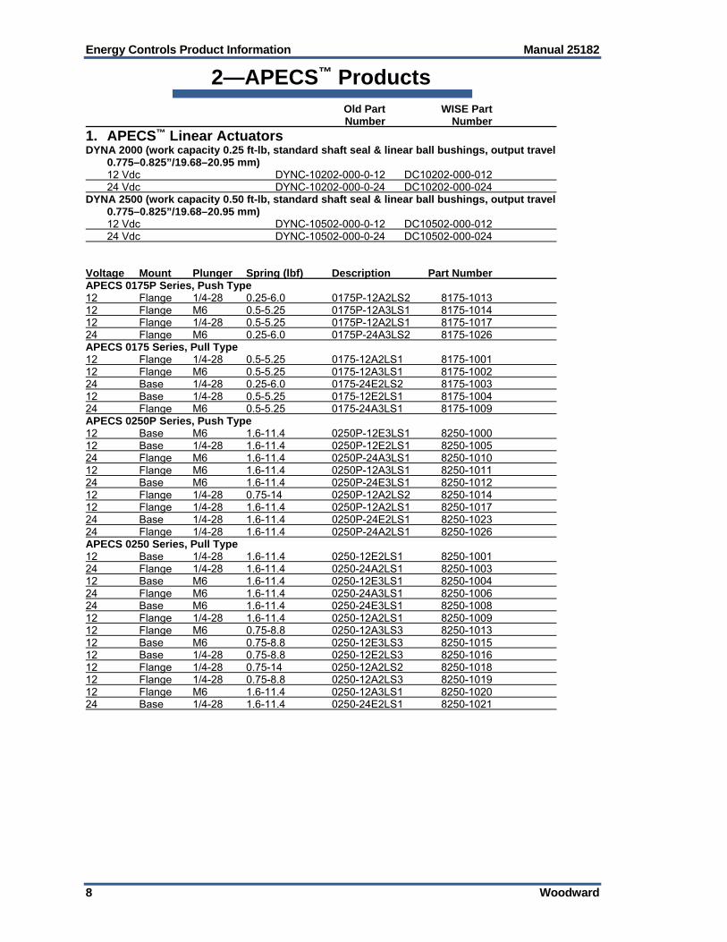
2—APECS™ Products Old Part WISE Part Number Number
1. APECS™ Linear Actuators DYNA 2000 (work capacity 0.25 ft-lb, standard shaft seal & linear ball bushings, output travel
0.775–0.825”/19.68–20.95 mm) 12 Vdc DYNC-10202-000-0-12 DC10202-000-012 24 Vdc DYNC-10202-000-0-24 DC10202-000-024 DYNA 2500 (work capacity 0.50 ft-lb, standard shaft seal & linear ball bushings, output travel
0.775–0.825”/19.68–20.95 mm) 12 Vdc DYNC-10502-000-0-12 DC10502-000-012 24 Vdc DYNC-10502-000-0-24 DC10502-000-024 Voltage Mount Plunger Spring (lbf) Description Part Number APECS 0175P Series, Push Type 12 Flange 1/4-28 0.25-6.0 0175P-12A2LS2 8175-1013 12 Flange M6 0.5-5.25 0175P-12A3LS1 8175-1014 12 Flange 1/4-28 0.5-5.25 0175P-12A2LS1 8175-1017 24 Flange M6 0.25-6.0 0175P-24A3LS2 8175-1026 APECS 0175 Series, Pull Type 12 Flange 1/4-28 0.5-5.25 0175-12A2LS1 8175-1001 12 Flange M6 0.5-5.25 0175-12A3LS1 8175-1002 24 Base 1/4-28 0.25-6.0 0175-24E2LS2 8175-1003 12 Base 1/4-28 0.5-5.25 0175-12E2LS1 8175-1004 24 Flange M6 0.5-5.25 0175-24A3LS1 8175-1009 APECS 0250P Series, Push Type 12 Base M6 1.6-11.4 0250P-12E3LS1 8250-1000 12 Base 1/4-28 1.6-11.4 0250P-12E2LS1 8250-1005 24 Flange M6 1.6-11.4 0250P-24A3LS1 8250-1010 12 Flange M6 1.6-11.4 0250P-12A3LS1 8250-1011 24 Base M6 1.6-11.4 0250P-24E3LS1 8250-1012 12 Flange 1/4-28 0.75-14 0250P-12A2LS2 8250-1014 12 Flange 1/4-28 1.6-11.4 0250P-12A2LS1 8250-1017 24 Base 1/4-28 1.6-11.4 0250P-24E2LS1 8250-1023 24 Flange 1/4-28 1.6-11.4 0250P-24A2LS1 8250-1026 APECS 0250 Series, Pull Type 12 Base 1/4-28 1.6-11.4 0250-12E2LS1 8250-1001 24 Flange 1/4-28 1.6-11.4 0250-24A2LS1 8250-1003 12 Base M6 1.6-11.4 0250-12E3LS1 8250-1004 24 Flange M6 1.6-11.4 0250-24A3LS1 8250-1006 24 Base M6 1.6-11.4 0250-24E3LS1 8250-1008 12 Flange 1/4-28 1.6-11.4 0250-12A2LS1 8250-1009 12 Flange M6 0.75-8.8 0250-12A3LS3 8250-1013 12 Base M6 0.75-8.8 0250-12E3LS3 8250-1015 12 Base 1/4-28 0.75-8.8 0250-12E2LS3 8250-1016 12 Flange 1/4-28 0.75-14 0250-12A2LS2 8250-1018 12 Flange 1/4-28 0.75-8.8 0250-12A2LS3 8250-1019 12 Flange M6 1.6-11.4 0250-12A3LS1 8250-1020 24 Base 1/4-28 1.6-11.4 0250-24E2LS1 8250-1021
Manual 25182 Energy Controls Product Information
Woodward 9
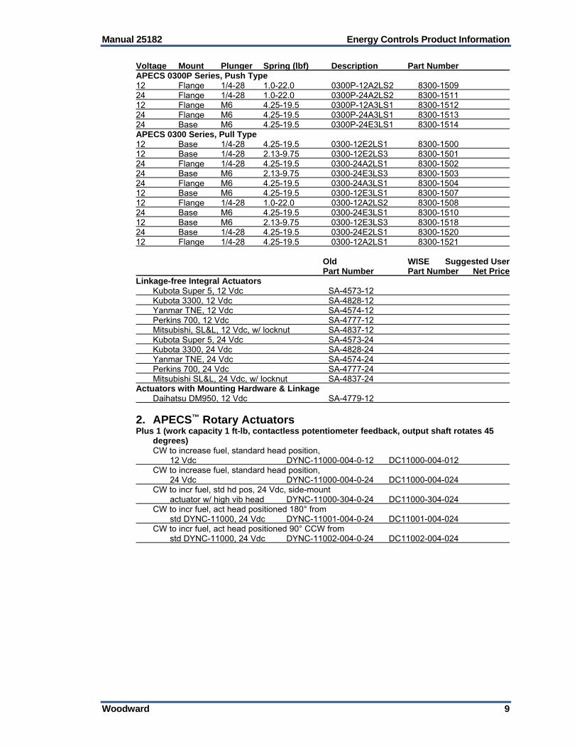
Voltage Mount Plunger Spring (lbf) Description Part Number APECS 0300P Series, Push Type 12 Flange 1/4-28 1.0-22.0 0300P-12A2LS2 8300-1509 24 Flange 1/4-28 1.0-22.0 0300P-24A2LS2 8300-1511 12 Flange M6 4.25-19.5 0300P-12A3LS1 8300-1512 24 Flange M6 4.25-19.5 0300P-24A3LS1 8300-1513 24 Base M6 4.25-19.5 0300P-24E3LS1 8300-1514 APECS 0300 Series, Pull Type 12 Base 1/4-28 4.25-19.5 0300-12E2LS1 8300-1500 12 Base 1/4-28 2.13-9.75 0300-12E2LS3 8300-1501 24 Flange 1/4-28 4.25-19.5 0300-24A2LS1 8300-1502 24 Base M6 2.13-9.75 0300-24E3LS3 8300-1503 24 Flange M6 4.25-19.5 0300-24A3LS1 8300-1504 12 Base M6 4.25-19.5 0300-12E3LS1 8300-1507 12 Flange 1/4-28 1.0-22.0 0300-12A2LS2 8300-1508 24 Base M6 4.25-19.5 0300-24E3LS1 8300-1510 12 Base M6 2.13-9.75 0300-12E3LS3 8300-1518 24 Base 1/4-28 4.25-19.5 0300-24E2LS1 8300-1520 12 Flange 1/4-28 4.25-19.5 0300-12A2LS1 8300-1521 Old WISE Suggested User Part Number Part Number Net Price Linkage-free Integral Actuators Kubota Super 5, 12 Vdc SA-4573-12 Kubota 3300, 12 Vdc SA-4828-12 Yanmar TNE, 12 Vdc SA-4574-12 Perkins 700, 12 Vdc SA-4777-12 Mitsubishi, SL&L, 12 Vdc, w/ locknut SA-4837-12 Kubota Super 5, 24 Vdc SA-4573-24 Kubota 3300, 24 Vdc SA-4828-24 Yanmar TNE, 24 Vdc SA-4574-24 Perkins 700, 24 Vdc SA-4777-24 Mitsubishi SL&L, 24 Vdc, w/ locknut SA-4837-24 Actuators with Mounting Hardware & Linkage Daihatsu DM950, 12 Vdc SA-4779-12
2. APECS™ Rotary Actuators Plus 1 (work capacity 1 ft-lb, contactless potentiometer feedback, output shaft rotates 45
degrees) CW to increase fuel, standard head position, 12 Vdc DYNC-11000-004-0-12 DC11000-004-012 CW to increase fuel, standard head position, 24 Vdc DYNC-11000-004-0-24 DC11000-004-024 CW to incr fuel, std hd pos, 24 Vdc, side-mount actuator w/ high vib head DYNC-11000-304-0-24 DC11000-304-024 CW to incr fuel, act head positioned 180° from std DYNC-11000, 24 Vdc DYNC-11001-004-0-24 DC11001-004-024 CW to incr fuel, act head positioned 90° CCW from std DYNC-11000, 24 Vdc DYNC-11002-004-0-24 DC11002-004-024

Energy Controls Product Information Manual 25182
10 Woodward
Old Part WISE Part Number Number CCW to increase fuel, standard head position, 24 Vdc DYNC-11004-004-0-24 DC11004-004-024 CCW to incr fuel, act head positioned 180° from std DYNC-11004, 24 Vdc, side-mount actuator w/ high vib head DYNC-11006-304-0-24 DC11006-304-024 DYNA 8000 (work capacity 1.0 ft-lb, current feedback 12 or 24 Vdc, terminal strip connection) Output shaft rotates 35°, CW to incr fuel, std head pos, 12 Vdc DYNC-11020-000-0-12 DC11020-000-012 Output shaft rotates 35°, CW to incr fuel, std head pos, 24 Vdc DYNC-11020-000-0-24 DC11020-000-024 CW to incr fuel, std head pos, side-mounted actuator, 12 Vdc DYNC-11020-300-0-12 DC11020-300-012 CW to incr fuel, std head pos, side-mounted actuator, 24 Vdc DYNC-11020-300-0-24 DC11020-300-024 CW to incr fuel, act head pos 180° from std DYNC-11020, 12 Vdc DYNC-11021-000-0-12 DC11021-000-012 CW to incr fuel, act head pos 180° from std DYNC-11020, 24 Vdc DYNC-11021-000-0-24 DC11021-000-024 CW to incr fuel, side-mounted actuator, act head pos 180° from std DYNC-11020, 12 Vdc DYNC-11021-300-0-12 DC11021-300-012 CW to incr fuel, side-mounted actuator, act head pos 180° from std DYNC-11020, 24 Vdc DYNC-11021-300-0-24 DC11021-300-024 CW to incr fuel, act head pos 90° CCW from std DYNC-11020, 12 Vdc DYNC-11022-000-0-12 DC11022-000-012 CW to incr fuel, act head pos 90° CCW from std DYNC-11020, 24 Vdc DYNC-11022-000-0-24 DC11022-000-024 CW to incr fuel, act head pos 90° CW from std DYNC-11020, 24 Vdc DYNC-11023-000-0-24 DC11023-000-024 CW to incr fuel, side-mounted actuator, act head pos 90° CW from std DYNC-11020, 24 Vdc DYNC-11023-300-0-24 DC11023-300-024 Output shaft rotates 35°, CCW to incr fuel, std head pos, 12 Vdc DYNC-11024-000-0-12 DC11024-000-012 Output shaft rotates 35°, CCW to incr fuel, std head pos, 24 Vdc DYNC-11024-000-0-24 DC11024-000-024 CCW to incr fuel, std head pos, side-mounted actuator, 12 Vdc DYNC-11024-300-0-12 DC11024-300-012 CCW to incr fuel, std head pos, side-mounted actuator, 24 Vdc DYNC-11024-300-0-24 DC11024-300-024 CCW to incr fuel, act head pos 90° CW from std DYNC-11024, 24 Vdc DYNC-11025-000-0-24 DC11025-000-024 CCW to incr fuel, side-mounted actuator, act head pos 180° from std DYNC-11024, 24 Vdc DYNC-11026-300-0-24 DC11026-300-024 DYNA 8200 (work capacity 2.1 ft-lb, output shaft rotates 45 degrees, dual output shafts) Std head rotation, 12 Vdc DYNC-12000-000-0-12 DC12000-000-012 Std head rotation, 24 Vdc DYNC-12000-000-0-24 DC12000-000-024 Hd rot 180° from std, 12 Vdc DYNC-12001-000-0-12 DC12001-000-012 Hd rot 180° from std, 24 Vdc DYNC-12001-000-0-24 DC12001-000-024 Hd rot 90° CCW from std, 12 Vdc DYNC-12002-000-0-12 DC12002-000-012 Plus 4 (work capacity 4 ft-lb, contactless potentiometer feedback, output shaft rotates 45 degrees, 24 Vdc) CW & CCW via through-shaft DYNC-14000-001-0-24 DC14000-001-024 Stanadyne (Stanadyne integrated governors for Stanadyne “D” series injection pumps) Standard, 12 Vdc DYNC-70025-002-0-12 DC70025-002-012 Standard, 24 Vdc DYNC-70025-002-0-24 DC70025-002-024 Int gov sealed unit, 12 Vdc DYNC-70025-003-0-12 DC70025-003-012 Int gov sealed unit, 24 Vdc DYNC-70025-003-0-24 DC70025-003-024 APECS 0200R 12 Vdc SA-4928-12 24 Vdc SA-4928-24

Manual 25182 Energy Controls Product Information
Woodward 11
Old Part WISE Part Number Number
3. APECS™ Controllers APECS 500 Controller (manually adjusted, computer calibrated) APECS 500 SA-4492 APECS 2000 Controller (manually adjusted, PID controller) APECS 2000 SA-4389 APECS 3000 Controller (computer calibrated) APECS 3000 SA-4450 APECS 3100 SA-4451 APECS 3200 SA-4452 APECS 3400 SA-4471 APECS 4500 Controller (computer calibrated) APECS 4500 SA-4489 APECS 4500 with CAN 8800-1006 APECS Calibration Tool & Kits (for controllers 2000, 3000, 4000, 4500, 5000) For all series 500 controllers SA-5206 For all series 3000 controllers SA-4455 For all series 4000 controllers SA-4475 For all series 4500 & 5000 controllers SA-4488 Connector kit for all series 4000 controllers SA-4473 Connector kit for all series 4500 & 5000 cont. SA-4490 DPG 2100 Series (low-cost, digital programmable control w/ single gain potentiometer;
frequency range 1000 to 11000 Hz, 9 to 30 Vdc) For all DYNA non position feedback actuators on either diesel or gas engine applications, fully programmable DPG-2101-002 For DYNA 2000/2500 actuators on natural gas or gasoline engine applications, overall gain adj only; works with all DYNA non-position feedback actuators; diesel or gas engine applications DPG-2102 For DYNC-60010/60020 gas valves (Phase II gas valves), overall gain adj only DPG-2103 Replaces DYN1-1078x Stanadyne series controls DPG-2104 For Power Flow integrated throttle body (Phase III gas valves), overall gain adj only DPG-2105 12-pin Molex connector, ignition speed sensing, 2 speed set points, idle speed & remote incr./decr. DPG-2145-002 12-pin Molex connector, magnetic pickup speed input, 2 speed set points, idle speed & remote incr./decr. DPG-2155-002 DPG 2200 Series (digital programmable control, full PID configuration, start-up smoke
control, DYNA II compatibility, remote speed, idle/run, single-point torque limiting, pushbutton selection, parameter setup & serial port interface; frequency range 1000 to 11000 Hz, 9 to 30 Vdc)
Replaces DYN1-1065x, DYN1-1068x, DYN1-1069x, DYN1-1075x, DYN1-1079x series controls DPG-2201-002 Same as DPG 2201 except remote speed input from potentiometer DPG-2223-002 DPG 2300 Series (for both diesel and gas engines used in off-highway mobile applications;
automatic food pedal calibration, adjustable acceleration/deceleration, adjustable ramps, start-up routines, & torque limits)
13-wire Euro connector & MPU for speed input DPG-2302-002 13-wire Euro connector & ignition for speed input DPG-2345-002 Same as DPG 2223-001 except tuned for Cummins EFC valve DPG-2401-002

Energy Controls Product Information Manual 25182
12 Woodward
Old Part WISE Part Number Number Actuator Mounted Controller (engine rpm/speed controller for use with +1, +4, +6, +8/16
actuators, 24 Vdc) Pickup signal frequency operating range at maximum engine rpm 2500 to 5000 Hz DYN1-10004-002-0-24 8270-1059 Pickup signal frequency operating range at maximum engine rpm 5000 to 9500 Hz DYN1-10006-002-0-24 8270-1068 Panel Mounted Controller (engine rpm/speed controller for use with +1, +4, +6, +8/16
actuators, 24 Vdc; basic circuit same as actuator mounted controller) Pickup signal frequency operating range at maximum engine rpm 2500 to 5000 Hz, CE Rated, 12 Vdc DYN1-10504-004-0-12 8270-1078 Pickup signal frequency operating range at maximum engine rpm 2500 to 5000 Hz, CE Rated, 24 Vdc DYN1-10504-004-0-24 8270-1060 Pickup signal frequency operating range at maximum engine rpm 5000 to 9500 Hz, CE Rated, 24 Vdc DYN1-10504-004-0-24 8270-1082 Panel Mounted Controller/DYNA 8000/8200/8400 (engine rpm/speed controller used with
DYNA 8000, 8200, & 8400 actuators; adjustment for GAIN, INTEGRAL, DERIVATIVE, & DROOP; can be used with ILS, load pulse, auto synch, etc)
Pickup frequency operating range at maximum engine rpm 2500 to 5000 Hz, 12 Vdc, CE Rated DYN1-10654-000-0-12 8270-1021 Pickup frequency operating range at maximum engine rpm 2500 to 5000 Hz, 24 Vdc, CE Rated DYN1-10654-000-0-24 8270-1004 Replaced by DPG-2201-001 or DPG-2223-001. DYN1-10654-001-0-24 8270-1072 Panel Mounted Controller/DYNA 2000/2500 (for small linear actuators) Pickup frequency operating range at maximum engine rpm 2500 to 5000 Hz, 12 Vdc DYN1-10704-000-0-12 8270-1008 Pickup frequency operating range at maximum engine rpm 2500 to 5000 Hz, 12 Vdc DYN1-10704-000-0-24 8270-1050 Pickup frequency operating range at maximum engine rpm 2500 to 5000 Hz, 12 Vdc, CE Rated DYN1-10704-002-0-12 8270-1048 Pickup frequency operating range at maximum engine rpm 2500 to 5000 Hz, 12 Vdc, CE Rated DYN1-10704-002-0-24 8270-1055 Pickup frequency operating range at maximum engine rpm 5000 to 9500 Hz, 12 Vdc DYN1-10716-000-0-12 DI10716-000-012 Pickup frequency operating range at maximum engine rpm 5000 to 9500 Hz, 12 Vdc DYN1-10716-000-0-24 8270-1087 PC Board Controller/DYNA 2000/2500 (linear actuator w/ low gain circuit for cold engine
starting; gas engine applications, no enclosure, 12 Vdc) Pickup frequency operating range at maximum engine rpm 2500 to 5000 Hz DYN1-10744-000-0-12 8270-1027 Panel Mounted Controller/DYNA 2000/2500 (can be used w/ ILS, load pulse, auto
synchronizer, etc) Pickup frequency operating range at maximum engine rpm 2500 to 5000 Hz, 12 Vdc DYN1-10754-000-0-12 8270-1015 Pickup frequency operating range at maximum engine rpm 2500 to 5000 Hz, 24 Vdc DYN1-10754-000-0-24 8270-1038 Pickup frequency operating range at maximum engine rpm 5000 to 9500 Hz, 12 Vdc DYN1-10756-000-0-12 8270-1051 Pickup frequency operating range at maximum engine rpm 2500 to 5000 Hz, CE Rated, suggested replacement DPG-2201-001 or DPG-2223-001 DYN1-10754-001-0-12 8270-1018 Pickup frequency operating range at maximum engine rpm 2500 to 5000 Hz, CE Rated, suggested replacement DPG-2201-001 or DPG-2223-001 DYN1-10754-001-0-24 8270-1036

Manual 25182 Energy Controls Product Information
Woodward 13
Old Part WISE Part Number Number Panel Mounted Controller/Stanadyne “D” Series () Pickup frequency operating range at maximum engine rpm 2500 to 5000 Hz, 12 Vdc DYN1-10784-000-0-12 8270-1058 Pickup frequency operating range at maximum engine rpm 2500 to 5000 Hz, 24 Vdc DYN1-10784-000-0-24 8270-1074 Pickup frequency operating range at maximum engine rpm 2500 to 5000 Hz, CE Rated, suggested replacement DPG-2104 or DPG-2101-001 12 Vdc DYN1-10784-003-0-12 8270-1035 Pickup frequency operating range at maximum engine rpm 2500 to 5000 Hz, CE Rated, suggested replacement DPG-2104 or DPG-2101-001 24 Vdc DYN1-10784-003-0-24 8270-1075 Pickup frequency operating range at maximum engine rpm 2500 to 5000 Hz, 12 Vdc DYN1-10794-000-0-12 8270-1013 Pickup frequency operating range at maximum engine rpm 2500 to 5000 Hz, 24 Vdc DYN1-10794-000-0-24 8270-1014 Pickup frequency operating range at maximum engine rpm 2500 to 5000 Hz, 12 Vdc, CE Rated DYN1-10794-002-0-012 8270-1033
4. APECS™ Speed Switches and Sensors EPS 1000 Engine Protection System EPS 100 Module SA-4478 EPS 100 Calibration Tool Kit SA-4479 DSS-2 Electronic Speed Switch DSS-2 Digital Speed Switch, 2-channel 8800-1001 Magnetic Pickup SAE (5/8-18 UNF-2A) 2-1/8” (54 mm) insertion depth DYNT-10100 3-5/8” (92 mm) insertion depth DYNT-10200 3/4" (19 mm) insertion depth DYNT-10300 2-5/8” (66 mm) insertion depth DYNT-10400 5-5/8” (142 mm) insertion depth DYNT-10500 4-5/8” (117 mm) insertion depth DYNT-10600 5/8-18 UNF thread, 2 open leads SA-4424 5/8-18 UNF thrd, chisel tip, req. SA-1707-010 SA-2170 5/8-18 UNF thread, req. SA-1707-010 conn. SA-2171-A Connector & shielded cable assy, 10 ft (3 m) SA-1707-010 Magnetic Pickup Metric (M16 x 1.5-6g) 2-1/8” (54 mm) insertion depth DYNT-11100 3-5/8” (92 mm) insertion depth DYNT-11200 3/4” (19 mm) insertion depth DYNT-11300 2-5/8” (66 mm) insertion depth DYNT-11400 5-5/8” (142 mm) insertion depth DYNT-11500 4-5/8” (117 mm) insertion depth DYNT-11600 Magnetic Pickup SAE (3/4-16, 2 unshielded 36” 16 AWG leads) 2.36” (59.94 mm) insertion depth DYNT-13200 3.30” (83.80 mm) insertion depth DYNT-13300 Magnetic Pickup UNF (3/4-16) 2 open leads SA-4423 Magnetic Pickup SAE High Output (5/8-18 UNF-2A) 4.0” (100.0 mm) insertion depth DYNT-15200 3.0” (75.0 mm) insertion depth DYNT-15400 5.0” (126.0 mm) insertion depth DYNT-15600 Magnetic Pickup SAE (3/8-24 UNF-2A, includes 6’ shielded harness, -.78” insertion) 0.78” insertion depth DYNT-17100 1.65” insertion depth DYNT-17150 2.05” insertion depth DYNT-17200 DT17200-001-000 3.78” insertion depth DYNT-17400 Magnetic Pickup SAE (3/4-16, includes 6’ shielded harness) 2.1” insertion depth DYNT-19200 Magnetic Pickup Fittings 3/4-16 to 5/8-18 DYNC-600-1 DC600-001-0-00 3/4-16 to 3/8-24 DYNC-600-2 DC600-002-0-00 5/8-18 to 3/8-24 DYNC-600-3 DC600-003-0-00
Energy Controls Product Information Manual 25182
14 Woodward
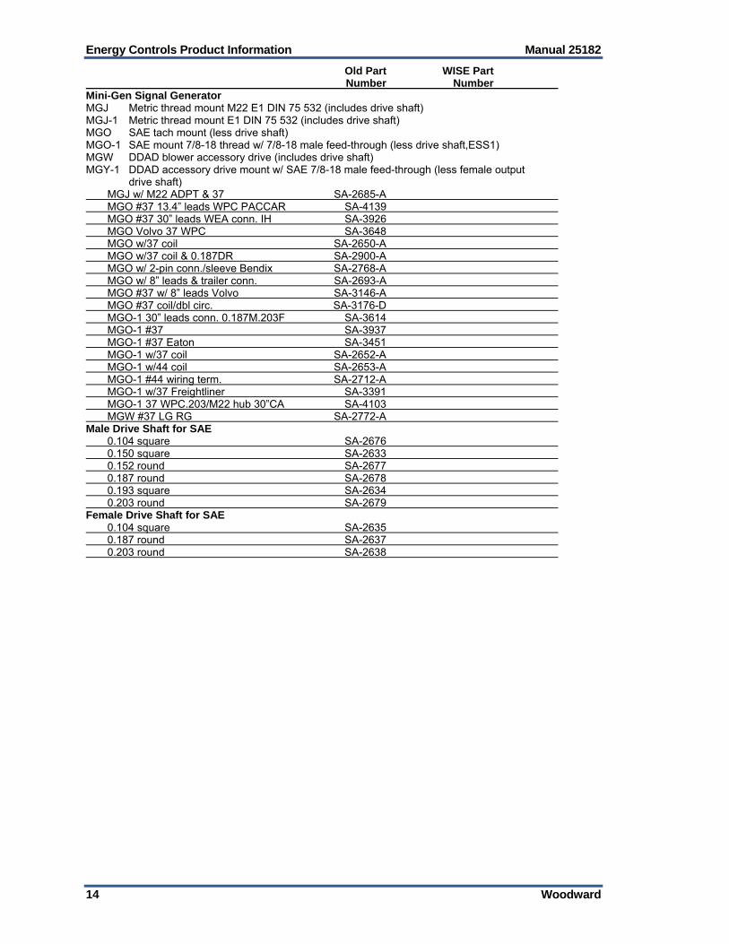
Old Part WISE Part Number Number Mini-Gen Signal Generator MGJ Metric thread mount M22 E1 DIN 75 532 (includes drive shaft) MGJ-1 Metric thread mount E1 DIN 75 532 (includes drive shaft) MGO SAE tach mount (less drive shaft) MGO-1 SAE mount 7/8-18 thread w/ 7/8-18 male feed-through (less drive shaft,ESS1) MGW DDAD blower accessory drive (includes drive shaft) MGY-1 DDAD accessory drive mount w/ SAE 7/8-18 male feed-through (less female output drive shaft) MGJ w/ M22 ADPT & 37 SA-2685-A MGO #37 13.4” leads WPC PACCAR SA-4139 MGO #37 30” leads WEA conn. IH SA-3926 MGO Volvo 37 WPC SA-3648 MGO w/37 coil SA-2650-A MGO w/37 coil & 0.187DR SA-2900-A MGO w/ 2-pin conn./sleeve Bendix SA-2768-A MGO w/ 8” leads & trailer conn. SA-2693-A MGO #37 w/ 8” leads Volvo SA-3146-A MGO #37 coil/dbl circ. SA-3176-D MGO-1 30” leads conn. 0.187M.203F SA-3614 MGO-1 #37 SA-3937 MGO-1 #37 Eaton SA-3451 MGO-1 w/37 coil SA-2652-A MGO-1 w/44 coil SA-2653-A MGO-1 #44 wiring term. SA-2712-A MGO-1 w/37 Freightliner SA-3391 MGO-1 37 WPC.203/M22 hub 30”CA SA-4103 MGW #37 LG RG SA-2772-A Male Drive Shaft for SAE 0.104 square SA-2676 0.150 square SA-2633 0.152 round SA-2677 0.187 round SA-2678 0.193 square SA-2634 0.203 round SA-2679 Female Drive Shaft for SAE 0.104 square SA-2635 0.187 round SA-2637 0.203 round SA-2638

Manual 25182 Energy Controls Product Information
Woodward 15
Old Part WISE Part Number Number
5. APECS™ Accessories Remote Speed Controllers & Accessories Lock for DYNS-10000 DYNS-1 Remote speed-setting pot (5 k, 10-turn) w/ 499 k resistor & lock nut for pot DYNS-10000 Installation Kits General purpose kit for DYNA-8000 governor, no bracket in kit DYNK-10206 General purpose kit for DYNA-2000/2500 linear governor DYNK-10249 Detroit Diesel 16V71, 12V92, & 16V92, using DYNA-8200 actuator DYNK-10355 Cummins “C” Bosch P3000 “A” pump DYNK-10393 Harness Magnetic Pickup (2-conductor shielded cable w/ 90-degree 2-pin connector) Length 12’ (3.6 m) DYNK-44-2 DK44-002-0-00 Harness for Plus 1, Plus 4 (wiring for +1 or +4 actuator when using a panel-mounted DYN1-10504 controller) Length 12’ (3.6 m) DYNK-123-1 DK123-001-0-00 Connectors (mating electrical connectors, with cable clamp) Straight, mates w/ DYN1 control box DYNZ-46-01 DZ46-001-0-00 90 degrees, mates w/ DYN1 control box DYNZ-46-02 DZ46-002-0-00 Straight, mates with MPU DYNZ-46-13 DZ46-013-0-00 90 degrees, mates with MPU DYNZ-46-14 DZ46-014-0-00 APECS Actuator Mounting Hardware Only (kits are boxed, not assembled) Cummins C w/ Bosch A, MW, or P fuel pump and RSV governor; recommended actuator is SA-4506 w/ SA-4684 (S1 spring); Cummins bracket must be purchased from Cummins SA-4598 Kubota V2203-E; recommended actuator is SA-4502 w/ SA-4684 (S1 spring) SA-4457 APECS Actuator Accessories, Linkage (kits are bagged, not assembled) Long linkage kit, center to center 3.3 to 7.9” SA-4661 Short linkage kit, center to center 2.2 to 2.6” SA-4742 Clevis, fits actuators w/ 1/4-28 or M6 threads to rod ends below SA-4599 Spherical rod end, female, 1/4-28 SA-4619 Spherical rod end, male, 1/4-28 SA-4600 Threaded rod, 1/4-28 or M6 by 6” SA-4602
Energy Controls Product Information Manual 25182
16 Woodward
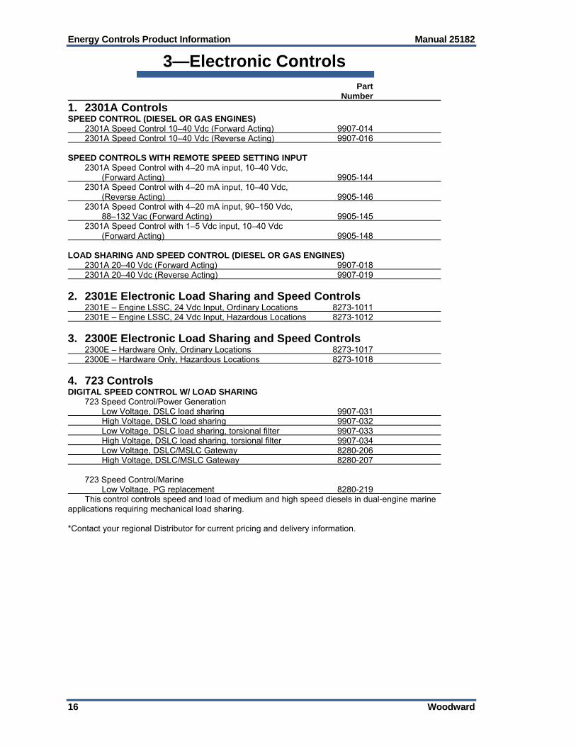
3—Electronic Controls Part Number
1. 2301A Controls SPEED CONTROL (DIESEL OR GAS ENGINES) 2301A Speed Control 10–40 Vdc (Forward Acting) 9907-014 2301A Speed Control 10–40 Vdc (Reverse Acting) 9907-016 SPEED CONTROLS WITH REMOTE SPEED SETTING INPUT 2301A Speed Control with 4–20 mA input, 10–40 Vdc, (Forward Acting) 9905-144 2301A Speed Control with 4–20 mA input, 10–40 Vdc, (Reverse Acting) 9905-146 2301A Speed Control with 4–20 mA input, 90–150 Vdc, 88–132 Vac (Forward Acting) 9905-145 2301A Speed Control with 1–5 Vdc input, 10–40 Vdc (Forward Acting) 9905-148 LOAD SHARING AND SPEED CONTROL (DIESEL OR GAS ENGINES) 2301A 20–40 Vdc (Forward Acting) 9907-018 2301A 20–40 Vdc (Reverse Acting) 9907-019
2. 2301E Electronic Load Sharing and Speed Controls 2301E – Engine LSSC, 24 Vdc Input, Ordinary Locations 8273-1011 2301E – Engine LSSC, 24 Vdc Input, Hazardous Locations 8273-1012
3. 2300E Electronic Load Sharing and Speed Controls 2300E – Hardware Only, Ordinary Locations 8273-1017 2300E – Hardware Only, Hazardous Locations 8273-1018
4. 723 Controls DIGITAL SPEED CONTROL W/ LOAD SHARING 723 Speed Control/Power Generation Low Voltage, DSLC load sharing 9907-031 High Voltage, DSLC load sharing 9907-032 Low Voltage, DSLC load sharing, torsional filter 9907-033 High Voltage, DSLC load sharing, torsional filter 9907-034 Low Voltage, DSLC/MSLC Gateway 8280-206 High Voltage, DSLC/MSLC Gateway 8280-207 723 Speed Control/Marine Low Voltage, PG replacement 8280-219 This control controls speed and load of medium and high speed diesels in dual-engine marine applications requiring mechanical load sharing. *Contact your regional Distributor for current pricing and delivery information.

Manual 25182 Energy Controls Product Information
Woodward 17
Part Number
5. 723PLUS Controls 723PLUS Control/Power Generation: DSLC load sharing, high voltage/low speed 8280-467 DSLC load sharing, low voltage 8280-412 DSLC load sharing, high voltage 8280-413 Analog load sharing, low voltage 8280-414 Analog load sharing, high voltage 8280-415 Analog load sharing, low voltage/low speed 8280-480 Analog load sharing, high voltage/low speed 8280-481 DSLC/MSLC Gateway w/ CMNDS, low voltage 8280-416 DSLC/MSLC Gateway w/ CMNDS, high voltage 8280-417 723PLUS Control/Marine: Single engine marine propulsion, low voltage/low speed 8280-418 Single engine marine propulsion, low voltage 8280-419 Dual engine marine load sharing, low voltage 8280-423 723PLUS Control/Industrial: Variable speed/process control, low voltage 8280-464 Variable speed control, low voltage 8280-410 723PLUS Position Control: 20–160 mA actuator 8262-092 Handheld Programmer for 723PLUS 9907-205
6. 828 Control (723PLUS) Hardware Platform for Distributors 828 Low Voltage, Hardware Only 9907-247 828 High Voltage, Hardware Only 9907-248
7. Custom Control Platforms AtlasSC 8273-040 AtlasSC - 1 Analog I/O Module 8273-041 AtlasSC - PowerSense 8273-042 AtlasSC - 1 Analog I/O Module, PowerSense 8273-043 Atlas-II 8273-584 Atlas-II - PowerSense 8273-586 Atlas-II - 1 Analog I/O Module 8273-565 Atlas-II - 1 Analog I/O Module, Profibus 8273-570 Atlas-II - 1 Analog I/O Module, DLE 8273-553 Atlas-II - 1 Analog I/O Module, PowerSense 8273-556 Atlas-II - 2 Analog I/O Modules 8273-571 Atlas-II - 2 Analog I/O Modules, Profibus 8273-552 Atlas-II - 2 Analog I/O Modules, Power Sense 8273-557 Atlas-II - 2 Analog I/O Modules, Power Sense, Profibus 8273-562 Atlas-II - 3 Analog I/O Modules 8273-555 Atlas-II - 3 Analog I/O Modules, Profibus 8273-560 Optional Atlas Accessories AtlasSC or AtlasPC Relay Kit – 12 channel w/ cable 8928-459 Flex500 Controls Flex500 - Panel Mount, LVDC, OCP 8200-1340 Flex500 - Panel Mount, HVAC/DC, OCP 8200-1341 Flex500 - Panel Mount, LVDC, Zone-2, OCP 8200-XXXX
Energy Controls Product Information Manual 25182
18 Woodward
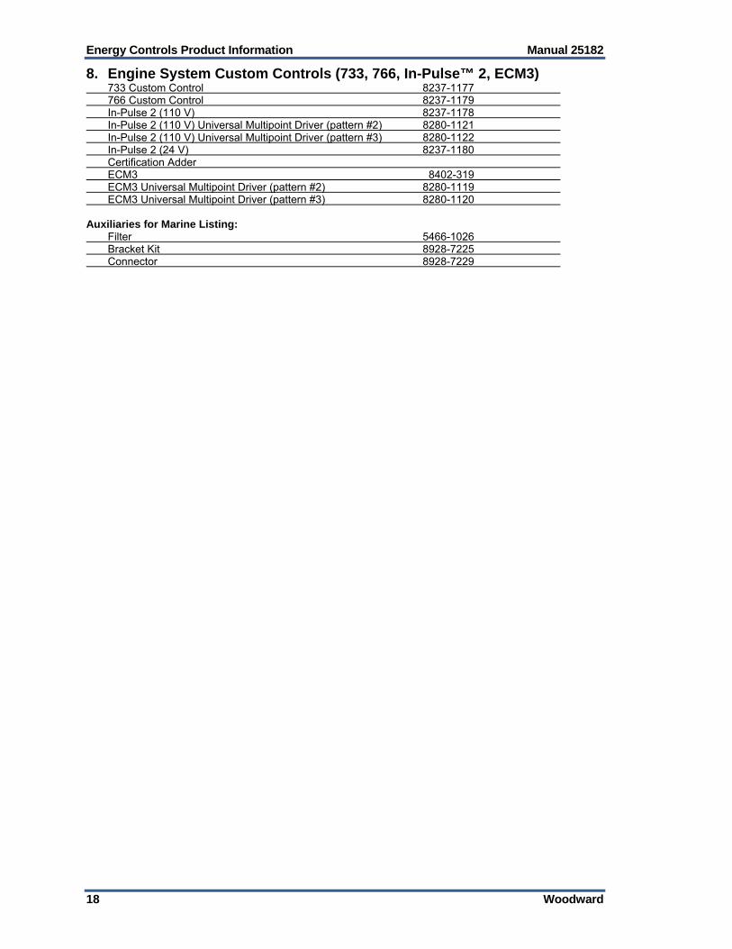
8. Engine System Custom Controls (733, 766, In-Pulse™ 2, ECM3) 733 Custom Control 8237-1177 766 Custom Control 8237-1179 In-Pulse 2 (110 V) 8237-1178 In-Pulse 2 (110 V) Universal Multipoint Driver (pattern #2) 8280-1121 In-Pulse 2 (110 V) Universal Multipoint Driver (pattern #3) 8280-1122 In-Pulse 2 (24 V) 8237-1180 Certification Adder ECM3 8402-319 ECM3 Universal Multipoint Driver (pattern #2) 8280-1119 ECM3 Universal Multipoint Driver (pattern #3) 8280-1120 Auxiliaries for Marine Listing: Filter 5466-1026 Bracket Kit 8928-7225 Connector 8928-7229

Manual 25182 Energy Controls Product Information
Woodward 19
4—Turbine Controls and Associated Devices Part Number
1. 2301E-ST Steam Turbine Controls 2301E-ST – Steam Turbine Control 8273-1013 2301E-ST – Steam Turbine Control, CSA Hazardous Loc 8273-1014
2. Peak® 150 Steam Turbine Controls 110 Vac/125 Vdc/NEMA 4/ without Modbus 9905-858 110 Vac/125 Vdc/NEMA 4X/ without Modbus 9905-864 110 Vac/125 Vdc/NEMA 4/ with Modbus 9905-861 110 Vac/125 Vdc/NEMA 4X/ with Modbus 9905-867 24 Vdc/NEMA 4/ without Modbus 9905-857 24 Vdc/NEMA 4X/ without Modbus 9905-863 24 Vdc/NEMA 4/ with Modbus 9905-860 24 Vdc/NEMA 4X/ with Modbus 9905-866 Hand Held Programmer 9907-205 Panel Mount Kit 8923-248
3. 505 Steam Turbine Controls 505 - LVDC, Ordinary Location 8200-1300 505 - HVAC/DC, Ordinary Location 8200-1301 505 - LVDC, Zone-2 Hazardous Location 8200-1302 505-XT - LVDC, Ordinary Location 8200-1310 (To be released Nov. 2015) 505-XT - HVAC/DC, Ordinary Location 8200-1311 (To be released Nov. 2015) 505-XT - LVDC, Zone-2 Hazardous Location 8200-1312 (To be released Nov. 2015) 505-Enhanced flush mount, HVAC 9907-1181 505-Enhanced flush mount, AC/DC 9907-1182 505-Enhanced flush mount, LVDC 9907-1183 505 Marine Certified 8923-1704 RemoteView - Software License 8928-5311 Old 505 to New 505 Retrofit Wiring Kit 5404-1801 Vibration Sensor - 4-20mA Accelerometer, 16' cable 8928-7482 Vibration Sensors - 4-20mA Proximity SEC of America 505CC-2 Compressor or ITCC Controller 505CC-2 Controller, Atlas-II, 18-32 Vdc 8301-1258 505CC-2 Configuration Support (site/application review) xxxx-xxxx Includes the following:
3 days of engineering support (at site or at Woodward) the creation of a site-specific configuration file ready to be uploaded into the control
NOTES: Travel & Living expenses, if required, are not included. Customer must supply applicable turbine & compressor performance information.

Energy Controls Product Information Manual 25182
20 Woodward
Part Number
4. 5009FT Steam Turbine Controls 5009FT w/ 2 24 VDC PS 8262-1068 5009FT w/ 2 120 V AC/DC PS 8262-1070 5009FT w/ 2 120 V AC/DC PS, Integ-Act 8262-1071 5009FT w/ 2 120 V AC/DC PS, CCT 8262-1049 5009FT w/ 2 120 V AC/DC PS, CCT, Integ-Act 8262-1050 5009FT w/ 2 120 V AC/DC PS, CCT, Extra Analog I/O 8262-1051 5009FT w/ 2 120 V AC/DC PS, CCT, Integ-Act, Extra Analog I/O 8262-1052 5009FT Cabinet, w/ 2 120 V AC/DC PS, CCT 8262-1155 5009FT Cabinet, w/ 2 120 V AC/DC PS, CCT + Integ Act kit 8262-1156 5009FT Cabinet, w/ 2 120 V AC/DC PS, CCT + Extra Analog I/O 8262-1157 5009FT w/ 2 220 VAC PS 8262-1072 5009FT w/ 2 220 VAC PS, Integ-Act 8262-1073 5009FT w/ 2 220 VAC PS, CCT 8262-1053 5009FT w/ 2 220 VAC PS, CCT, Integ-Act 8262-1054 5009FT w/ 2 220 VAC PS, CCT, Extra Analog I/O 8262-1055 5009FT w/ 2 220 VAC PS, CCT, Integ-Act, Extra Analog I/O 8262-1056 5009FT Cabinet, w/ 2 220 VAC PS, CCT 8262-1159 5009FT Cabinet, w/ 2 220 VAC PS, CCT, Integ-Act 8262-1160 5009FT Cabinet, w/ 2 220 VAC PS, CCT, Extra Analog I/O 8262-1161 5009FT Cabinet, w/ 2 220 VAC PS, CCT, Integ-Act, Ex. Anal. I/O 8262-1162 5009FT Computer-Configuration & Commissioning Tool (CCT) 8269-1011 5009FT Computer-Optional IFix Operator Interface (HMI) 8269-1012
5. Standard MicroNet Turbine Control Kits Standard MicroNet Turbine Kit, 8-Slot, 2 AC/DC Power Supplies 8262-1093 Standard MicroNet Turbine Kit, 8-Slot, 2 HVAC Power Supplies 8262-1094 Standard MicroNet Turbine Kit, 8-Slot, 2 LVDC Power Supplies 8262-1095 Global Steam Turbine Control Core Software License, GAP 5418-3915 For single valve & single extraction steam turbines only Single application license only Included within Standard MicroNet Turbine Control Kits Chassis – MicroNet-Plus, 8-Slot (QTY = 1) 5453-829 Module – Power Supply (QTY = 2) Kit Dependent Module – CPU5200 processor (QTY = 2) 5466-1245 Module – Analog Combo (QTY = 2) 5466-316 Module – Discrete Combo, (48) Inputs, (24) Outputs (QTY = 2) 5466-1158 FTM – Analog Combo (QTY = 2) 5501-371 FTM – Discrete Combo, (24) Inputs, (12) Outputs (QTY = 4) 5441-694 Cable – Analog, 10ft (QTY = 4) 5417-028 Cable – Discrete, 10ft (QTY = 4) 5417-173 Notes: System I/O can be expanded with the use of Woodward’s RTCnet or LinkNet-HT distributed
I/O modules. Cyber security can be enabled with purchase of license 8928-5222
6. GTC Gas Turbine Controls GTC100–1 Shaft GT, Dual Fuel 8262-1003 GTC100–1 Shaft GT, Dual Fuel, PwrSns 8262-1001 GTC200–2 Shaft GT, Dual Fuel, 1-Analog Module 8262-1002 GTC200–2 Shaft GT, Dual Fuel, 1-Analog Module, PwrSns 8262-1022 GTC250A–2 Shaft Aero, Dual Fuel, Atlas-II, w/ Profibus 8262-1031 GTC250A-FC – 2 Shaft Aero Type Gas Turbine Fuel Control 8262-1036
7. Servo Position Controllers (replace Digital Remote Final Drivers) SPC - Configurable Servo/Actuator Driver, Marine Certified 8200-226 Optional Mounting Bracket – Vertical 8928-7334
Manual 25182 Energy Controls Product Information
Woodward 21
Part Number
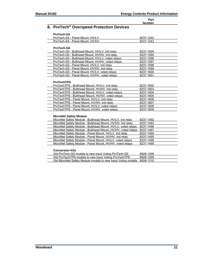
8. ProTech® Overspeed Protection Devices ProTech-SX ProTech-SX - Panel Mount, HV/LV 8237-1242 ProTech-SX - Panel Mount, HV/HV 8237-1243 ProTech-GII ProTech-GII - Bulkhead Mount, HV/LV, Ind relay 8237-1594 ProTech-GII - Bulkhead Mount, HV/HV, Ind relay 8237-1595 ProTech-GII - Bulkhead Mount, HV/LV, voted relays 8237-1596 ProTech-GII - Bulkhead Mount, HV/HV, voted relays 8237-1597 ProTech-GII - Panel Mount, HV/LV, Ind relay 8237-1598 ProTech-GII - Panel Mount, HV/HV, Ind relay 8237-1599 ProTech-GII - Panel Mount, HV/LV, voted relays 8237-1600 ProTech-GII - Panel Mount, HV/HV, voted relays 8237-1601 ProTechTPS ProTechTPS - Bulkhead Mount, HV/LV, Ind relay 8237-1602 ProTechTPS - Bulkhead Mount, HV/HV, Ind relay 8237-1603 ProTechTPS - Bulkhead Mount, HV/LV, voted relays 8237-1604 ProTechTPS - Bulkhead Mount, HV/HV, voted relays 8237-1605 ProTechTPS - Panel Mount, HV/LV, Ind relay 8237-1606 ProTechTPS - Panel Mount, HV/HV, Ind relay 8237-1607 ProTechTPS - Panel Mount, HV/LV, voted relays 8237-1608 ProTechTPS - Panel Mount, HV/HV, voted relays 8237-1609 MicroNet Safety Module MicroNet Safety Module - Bulkhead Mount, HV/LV, Ind relay 8237-1492 MicroNet Safety Module - Bulkhead Mount, HV/HV, Ind relay 8237-1493 MicroNet Safety Module - Bulkhead Mount, HV/LV, voted relays 8237-1496 MicroNet Safety Module - Bulkhead Mount, HV/HV, voted relays 8237-1497 MicroNet Safety Module - Panel Mount, HV/LV, Ind relay 8237-1494 MicroNet Safety Module - Panel Mount, HV/HV, Ind relay 8237-1495 MicroNet Safety Module - Panel Mount, HV/LV, voted relays 8237-1498 MicroNet Safety Module - Panel Mount, HV/HV, voted relays 8237-1499 Conversion Kits Old ProTech-GII models to new Input Voting ProTech-GII 8928-1308 Old ProTechTPS models to new Input Voting ProTechTPS 8928-1309 Old MicroNet Safety Module models to new Input Voting models 8928-1310
Energy Controls Product Information Manual 25182
22 Woodward
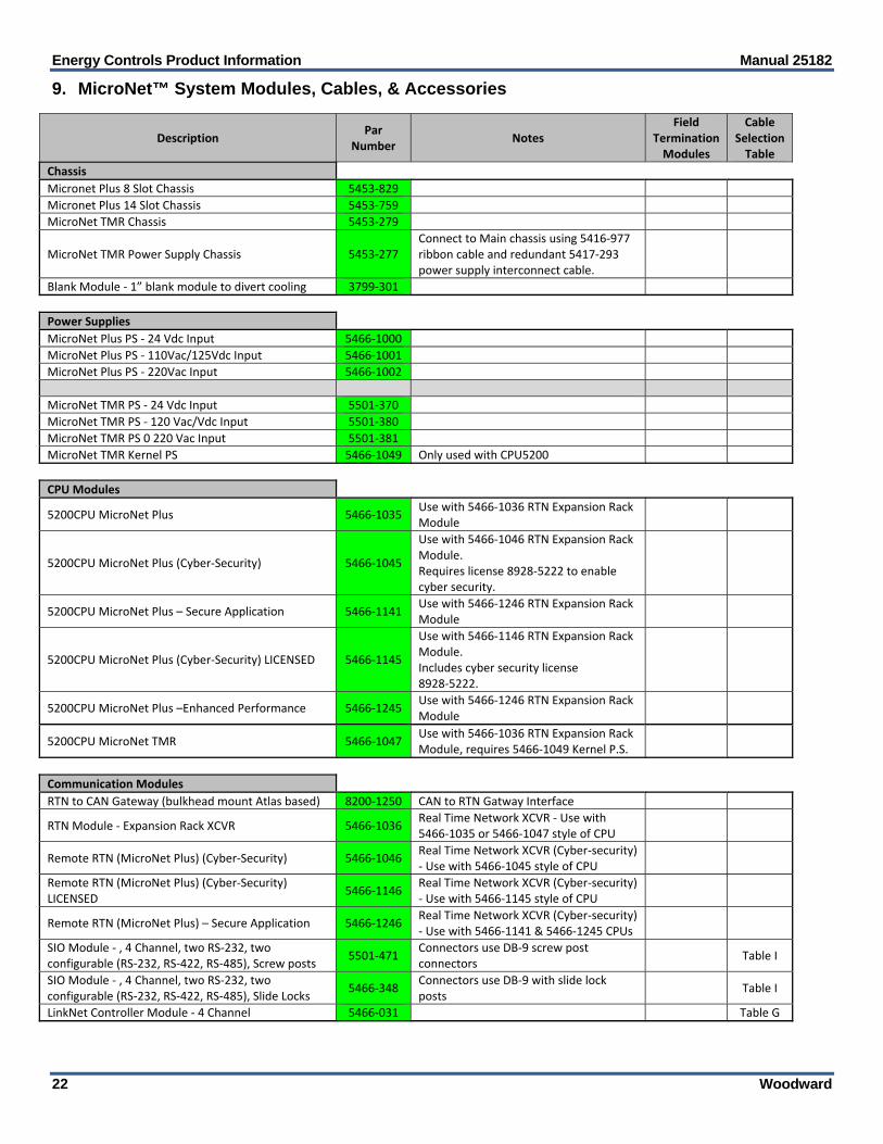
9. MicroNet™ System Modules, Cables, & Accessories
Description Par
Number Notes
Field Termination Modules
Cable Selection Table
Chassis
Micronet Plus 8 Slot Chassis 5453‐829
Micronet Plus 14 Slot Chassis 5453‐759
MicroNet TMR Chassis 5453‐279
MicroNet TMR Power Supply Chassis 5453‐277 Connect to Main chassis using 5416‐977 ribbon cable and redundant 5417‐293 power supply interconnect cable.
Blank Module ‐ 1” blank module to divert cooling 3799‐301
Power Supplies
MicroNet Plus PS ‐ 24 Vdc Input 5466‐1000
MicroNet Plus PS ‐ 110Vac/125Vdc Input 5466‐1001
MicroNet Plus PS ‐ 220Vac Input 5466‐1002
MicroNet TMR PS ‐ 24 Vdc Input 5501‐370
MicroNet TMR PS ‐ 120 Vac/Vdc Input 5501‐380
MicroNet TMR PS 0 220 Vac Input 5501‐381
MicroNet TMR Kernel PS 5466‐1049 Only used with CPU5200
CPU Modules
5200CPU MicroNet Plus 5466‐1035 Use with 5466‐1036 RTN Expansion Rack Module
5200CPU MicroNet Plus (Cyber‐Security) 5466‐1045
Use with 5466‐1046 RTN Expansion Rack Module. Requires license 8928‐5222 to enable cyber security.
5200CPU MicroNet Plus – Secure Application 5466‐1141 Use with 5466‐1246 RTN Expansion Rack Module
5200CPU MicroNet Plus (Cyber‐Security) LICENSED 5466‐1145
Use with 5466‐1146 RTN Expansion Rack Module. Includes cyber security license 8928‐5222.
5200CPU MicroNet Plus –Enhanced Performance 5466‐1245 Use with 5466‐1246 RTN Expansion Rack Module
5200CPU MicroNet TMR 5466‐1047 Use with 5466‐1036 RTN Expansion Rack Module, requires 5466‐1049 Kernel P.S.
Communication Modules
RTN to CAN Gateway (bulkhead mount Atlas based) 8200‐1250 CAN to RTN Gatway Interface
RTN Module ‐ Expansion Rack XCVR 5466‐1036 Real Time Network XCVR ‐ Use with 5466‐1035 or 5466‐1047 style of CPU
Remote RTN (MicroNet Plus) (Cyber‐Security) 5466‐1046 Real Time Network XCVR (Cyber‐security) ‐ Use with 5466‐1045 style of CPU
Remote RTN (MicroNet Plus) (Cyber‐Security) LICENSED
5466‐1146 Real Time Network XCVR (Cyber‐security) ‐ Use with 5466‐1145 style of CPU
Remote RTN (MicroNet Plus) – Secure Application 5466‐1246 Real Time Network XCVR (Cyber‐security) ‐ Use with 5466‐1141 & 5466‐1245 CPUs
SIO Module ‐ , 4 Channel, two RS‐232, two configurable (RS‐232, RS‐422, RS‐485), Screw posts
5501‐471 Connectors use DB‐9 screw post connectors
Table I
SIO Module ‐ , 4 Channel, two RS‐232, two configurable (RS‐232, RS‐422, RS‐485), Slide Locks
5466‐348 Connectors use DB‐9 with slide lock posts
Table I
LinkNet Controller Module ‐ 4 Channel 5466‐031 Table G

Manual 25182 Energy Controls Product Information
Woodward 23
Input Modules
Discrete Input ‐ 48 channel, 24 VDC 5464‐643 24 Vdc w/o LEDs, common bus, Requires 2 FTM's & 1 cable to each FTM. Total of 2 cables.
5437‐419, 5437‐687
Table K
Speed Sensor ‐ 4 channel, MPU 5464‐658 5437‐523 Table J
Speed Sensor ‐ 4 channel, MPU, Isolated 5466‐404 Same as 5464‐658 except has isolated power for LOCOP
5437‐523 Table J
Speed Sensor ‐ 4 channel, Proximity Probe 5464‐659 5437‐523 Table J
Speed Sensor ‐ 4 channel, MPU / Eddy Probe 5464‐834 5437‐523 Table J
Speed Sensor ‐ 4 channel, MPU / Proximity Probe 5464‐850 5437‐523 Table J
4‐20 mA ‐ 8 channel, Isolated 5464‐334 5437‐523 Table J
0‐10 Vdc ‐ 8 channel, Isolated 5464‐335 5437‐523 Table J
Thermocouple ‐ 8 channel, Fail Low, Isolated 5464‐332 5437‐524 Table J
Thermocouple ‐ 8 channel, Fail High, Isolated 5464‐333 5437‐524 Table J
RTD ‐ 8 channel, 10 Ohm, Semi‐Isolated 5464‐336 5437‐523 Table J
RTD ‐ 8 channel, 100 Ohm, Semi‐Isolated 5464‐337 5437‐523 Table J
RTD ‐ 8 channel, 100 Ohm, Semi‐Isolated, High Temp 5464‐340 5437‐523 Table J
RTD ‐ 8 channel, 200 Ohm, Semi‐Isolated 5464‐338 5437‐523 Table J
RTD ‐ 8 channel, 500 Ohm, Semi‐Isolated 5464‐339 5437‐523 Table J
4‐20/TC/RTD ‐ 34 channel 5503‐279 High Density, Voltage Input Module, Requires 2 FTMs
5503‐282 (2)
Table M
Pressure Interface ‐ 2 Channel (4 transducers/channel)
5466‐326 See Pressure Transducer Assemblies 5437‐523 Table J
Output Modules
Discrete Output Driver‐ 64 channel 5464‐654 5441‐413 or 1751‐6091
Table K
4‐20 mA ‐ 8 channel 5464‐648 5437‐523 or 5501‐427 (TMR)
Table J
0‐1 mA ‐ 8 channel 5464‐649 5437‐523 or 5501‐427 (TMR)
Table J
0‐5 Vdc ‐ 8 channel 5464‐650 5437‐523 or 5501‐427 (TMR)
Table J
0‐10 Vdc ‐ 8 channel 5464‐652 5437‐523 or 5501‐427 (TMR)
Table J
Actuator Driver ‐ 2 channel +/‐ 12.25 mA Integrating or Proportional (software selectable) Outputs
5501‐428 Bi‐Polar( + )Actuator Driver 5437‐672 Table K
Actuator Driver ‐ 2 channel +/‐ 30 mA Integrating or Proportional (software selectable) Outputs
5501‐429 Bi‐Polar( + )Actuator Driver 5437‐672 Table K
Actuator Driver ‐ 2 channel +/‐ 60 mA Integrating or Proportional (software selectable) Outputs
5501‐430 Bi‐Polar( + )Actuator Driver 5437‐672 Table K
Actuator Driver ‐ 2 channel +/‐ 120 mA Integrating or Proportional (software selectable) Outputs
5501‐431 Bi‐Polar( + )Actuator Driver 5437‐672 Table K
Actuator Driver ‐ 2 channel +/‐ 245 mA Integrating or Proportional (software selectable) Outputs
5501‐432 Bi‐Polar( + )Actuator Driver 5437‐672 Table K
Actuator Driver ‐ 4 channel 0‐200 mA , Proportional Only Output
5464‐544 Uni‐Polar( + )Actuator Driver 5437‐525 Table A
Actuator Driver ‐ 4 channel 4‐20 mA , Proportional Only Output
5464‐545 Uni‐Polar( + )Actuator Driver 5437‐525 Table A
Real Time SIO ‐ Connects to GS/LQ & EM Drivers 5503‐267 Uses screw post connectors, Use w/ LQ Driver & EM Digital ‐ Multidrop is not allowed with this module
Energy Controls Product Information Manual 25182
24 Woodward
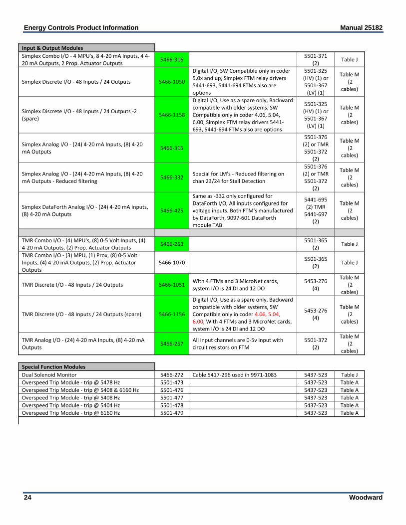
Input & Output Modules
Simplex Combo I/O ‐ 4 MPU's, 8 4‐20 mA Inputs, 4 4‐20 mA Outputs, 2 Prop. Actuator Outputs
5466‐316 5501‐371
(2) Table J
Simplex Discrete I/O ‐ 48 Inputs / 24 Outputs 5466‐1050
Digital I/O, SW Compatible only in coder 5.0x and up, Simplex FTM relay drivers 5441‐693, 5441‐694 FTMs also are options
5501‐325 (HV) (1) or 5501‐367 (LV) (1)
Table M (2
cables)
Simplex Discrete I/O ‐ 48 Inputs / 24 Outputs ‐2 (spare)
5466‐1158
Digital I/O, Use as a spare only, Backward compatible with older systems, SW Compatible only in coder 4.06, 5.04, 6.00, Simplex FTM relay drivers 5441‐693, 5441‐694 FTMs also are options
5501‐325 (HV) (1) or 5501‐367 (LV) (1)
Table M (2
cables)
Simplex Analog I/O ‐ (24) 4‐20 mA Inputs, (8) 4‐20 mA Outputs
5466‐315
5501‐376 (2) or TMR 5501‐372
(2)
Table M (2
cables)
Simplex Analog I/O ‐ (24) 4‐20 mA Inputs, (8) 4‐20 mA Outputs ‐ Reduced filtering
5466‐332 Special for LM's ‐ Reduced filtering on chan 23/24 for Stall Detection
5501‐376 (2) or TMR 5501‐372
(2)
Table M (2
cables)
Simplex DataForth Analog I/O ‐ (24) 4‐20 mA Inputs, (8) 4‐20 mA Outputs
5466‐425
Same as ‐332 only configured for DataForth I/O, All inputs configured for voltage inputs. Both FTM's manufactured by DataForth, 9097‐601 DataForth module TAB
5441‐695 (2) TMR 5441‐697
(2)
Table M (2
cables)
TMR Combo I/O ‐ (4) MPU's, (8) 0‐5 Volt Inputs, (4) 4‐20 mA Outputs, (2) Prop. Actuator Outputs
5466‐253 5501‐365
(2) Table J
TMR Combo I/O ‐ (3) MPU, (1) Prox, (8) 0‐5 Volt Inputs, (4) 4‐20 mA Outputs, (2) Prop. Actuator Outputs
5466‐1070 5501‐365
(2) Table J
TMR Discrete I/O ‐ 48 Inputs / 24 Outputs 5466‐1051 With 4 FTMs and 3 MicroNet cards, system I/O is 24 DI and 12 DO
5453‐276 (4)
Table M (2
cables)
TMR Discrete I/O ‐ 48 Inputs / 24 Outputs (spare) 5466‐1156
Digital I/O, Use as a spare only, Backward compatible with older systems, SW Compatible only in coder 4.06, 5.04, 6.00, With 4 FTMs and 3 MicroNet cards, system I/O is 24 DI and 12 DO
5453‐276 (4)
Table M (2
cables)
TMR Analog I/O ‐ (24) 4‐20 mA Inputs, (8) 4‐20 mA Outputs
5466‐257 All input channels are 0‐5v input with circuit resistors on FTM
5501‐372 (2)
Table M (2
cables)
Special Function Modules
Dual Solenoid Monitor 5466‐272 Cable 5417‐296 used in 9971‐1083 5437‐523 Table J
Overspeed Trip Module ‐ trip @ 5478 Hz 5501‐473 5437‐523 Table A
Overspeed Trip Module ‐ trip @ 5408 & 6160 Hz 5501‐476 5437‐523 Table A
Overspeed Trip Module ‐ trip @ 5408 Hz 5501‐477 5437‐523 Table A
Overspeed Trip Module ‐ trip @ 5404 Hz 5501‐478 5437‐523 Table A
Overspeed Trip Module ‐ trip @ 6160 Hz 5501‐479 5437‐523 Table A
Manual 25182 Energy Controls Product Information
Woodward 25
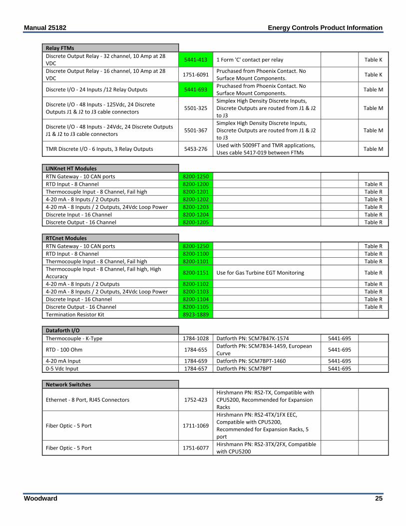
Relay FTMs
Discrete Output Relay ‐ 32 channel, 10 Amp at 28 VDC
5441‐413 1 Form 'C' contact per relay Table K
Discrete Output Relay ‐ 16 channel, 10 Amp at 28 VDC
1751‐6091 Pruchased from Phoenix Contact. No Surface Mount Components.
Table K
Discrete I/O ‐ 24 Inputs /12 Relay Outputs 5441‐693 Pruchased from Phoenix Contact. No Surface Mount Components.
Table M
Discrete I/O ‐ 48 Inputs ‐ 125Vdc, 24 Discrete Outputs J1 & J2 to J3 cable connectors
5501‐325 Simplex High Density Discrete Inputs, Discrete Outputs are routed from J1 & J2 to J3
Table M
Discrete I/O ‐ 48 Inputs ‐ 24Vdc, 24 Discrete Outputs J1 & J2 to J3 cable connectors
5501‐367 Simplex High Density Discrete Inputs, Discrete Outputs are routed from J1 & J2 to J3
Table M
TMR Discrete I/O ‐ 6 Inputs, 3 Relay Outputs 5453‐276 Used with 5009FT and TMR applications, Uses cable 5417‐019 between FTMs
Table M
LINKnet HT Modules
RTN Gateway ‐ 10 CAN ports 8200‐1250
RTD Input ‐ 8 Channel 8200‐1200 Table R
Thermocouple Input ‐ 8 Channel, Fail high 8200‐1201 Table R
4‐20 mA ‐ 8 Inputs / 2 Outputs 8200‐1202 Table R
4‐20 mA ‐ 8 Inputs / 2 Outputs, 24Vdc Loop Power 8200‐1203 Table R
Discrete Input ‐ 16 Channel 8200‐1204 Table R
Discrete Output ‐ 16 Channel 8200‐1205 Table R
RTCnet Modules
RTN Gateway ‐ 10 CAN ports 8200‐1250 Table R
RTD Input ‐ 8 Channel 8200‐1100 Table R
Thermocouple Input ‐ 8 Channel, Fail high 8200‐1101 Table R
Thermocouple Input ‐ 8 Channel, Fail high, High Accuracy
8200‐1151 Use for Gas Turbine EGT Monitoring Table R
4‐20 mA ‐ 8 Inputs / 2 Outputs 8200‐1102 Table R
4‐20 mA ‐ 8 Inputs / 2 Outputs, 24Vdc Loop Power 8200‐1103 Table R
Discrete Input ‐ 16 Channel 8200‐1104 Table R
Discrete Output ‐ 16 Channel 8200‐1105 Table R
Termination Resistor Kit 8923‐1889
Dataforth I/O Thermocouple ‐ K‐Type 1784‐1028 Datforth PN: SCM7B47K‐1574 5441‐695
RTD ‐ 100 Ohm 1784‐655 Datforth PN: SCM7B34‐1459, European Curve
5441‐695
4‐20 mA Input 1784‐659 Datforth PN: SCM7BPT‐1460 5441‐695
0‐5 Vdc Input 1784‐657 Datforth PN: SCM7BPT 5441‐695
Network Switches
Ethernet ‐ 8 Port, RJ45 Connectors 1752‐423 Hirshmann PN: RS2‐TX, Compatible with CPU5200, Recommended for Expansion Racks
Fiber Optic ‐ 5 Port 1711‐1069
Hirshmann PN: RS2‐4TX/1FX EEC, Compatible with CPU5200, Recommended for Expansion Racks, 5 port
Fiber Optic ‐ 5 Port 1751‐6077 Hirshmann PN: RS2‐3TX/2FX, Compatible with CPU5200

Energy Controls Product Information Manual 25182
26 Woodward
MicroNet System Cables
Table A ‐ NetCon Analog Cables
6 feet, Black 5416‐346 Netcon style exposed braid
8 feet, Black 5416‐347 Netcon style exposed braid
10 feet, Black 5416‐348 Netcon style exposed braid
12 feet, Black 5416‐349 Netcon style exposed braid
14 feet, Black 5416‐350 Netcon style exposed braid
16 feet, Black 5416‐351 Netcon style exposed braid
18 feet, Black 5416‐352 Netcon style exposed braid
20 feet, Black 5416‐353 Netcon style exposed braid
22 feet, Black 5416‐354 Netcon style exposed braid
26 feet, Black 5416‐355 Netcon style exposed braid
40 feet, Black 5416‐751 Netcon style exposed braid
Table B ‐ NetCon Discrete Cables
3 feet, Gray 5416‐332
6 feet, Gray 5416‐333
8 feet, Gray 5416‐334
10 feet, Gray 5416‐335
12 feet, Gray 5416‐336
14 feet, Gray 5416‐337
16 feet, Gray 5416‐338
18 feet, Gray 5416‐339
20 feet, Gray 5416‐340
22 feet, Gray 5416‐341
24 feet, Gray 5416‐342
26 feet, Gray 5416‐343
40 feet, Gray 5416‐750
Table C ‐ PS/2 keyboard/ Mouse Inactivated
Table D ‐ Transceiver Cables
10 feet, Metal Braid (Spare) 5415‐963 Not Compatible with CPU5200, Used with old Simplex or TMR MicroNet systems
T‐Module (Spare) 5437‐059 Not Compatible with CPU5200, Used with old Simplex or TMR MicroNet systems
Table E ‐ Ethernet Cables Inactivated
Table F ‐ Ethernet Cat‐5 Cables
1.5 feet 5417‐391
3 feet 5417‐392
7 feet 5417‐393
10 feet 5417‐394
15 feet 5417‐1243
25 feet 5417‐396
10 feet, crossover 5417‐414
14 feet, crossover 5417‐415
Table G ‐ LinkNet Cable
Wire ‐ 2 CONDUCTOR 22AWG, LOW CAP 2008‐349

Manual 25182 Energy Controls Product Information
Woodward 27
Table H ‐ MicroNet TMR Cables
PS Interconnect Cable, 40" 5417‐293 Used between Power Supply & Main Chassis
PS 50 pin Ribbon Cable, 6" 5416‐977 Used between Power Supply & Main Chassis
34 pin Ribbon Cable for Relay FTM interconnect. 6" 5417‐019 Used between FTMs 5453‐276 as interconnect cable
Table I ‐ RS232 Serial Port Cables
9 Pin DB ‐ Male to Female, Extension, 6 feet 5417‐411
9 Pin DB ‐ Male to Female, Extension, 10 feet 5417‐412
9 Pin DB ‐ Male to Female, Extension, 15 feet 5417‐413
Table J ‐ Low Density Analog Cables
3 feet, Black 5417‐296 MicroNet style‐‐ no exposed braid
6 feet, Black 5417‐026 MicroNet style‐‐ no exposed braid
8 feet, Black 5417‐027 MicroNet style‐‐ no exposed braid
10 feet, Black 5417‐028 MicroNet style‐‐ no exposed braid
12 feet, Black 5417‐029 MicroNet style‐‐ no exposed braid
14 feet, Black 5417‐030 MicroNet style‐‐ no exposed braid
16 feet, Black 5417‐031 MicroNet style‐‐ no exposed braid
18 feet, Black 5417‐032 MicroNet style‐‐ no exposed braid
20 feet, Black 5417‐033 MicroNet style‐‐ no exposed braid
22 feet, Black 5417‐034 MicroNet style‐‐ no exposed braid
26 feet, Black 5417‐035 MicroNet style‐‐ no exposed braid
40 feet, Black 5417‐036 MicroNet style‐‐ no exposed braid
Table K ‐ Low Density Discrete Cables
3 feet, Gray 5417‐037
6 feet, Gray 5417‐038
8 feet, Gray 5417‐039
10 feet, Gray 5417‐040
12 feet, Gray 5417‐041
14 feet, Gray 5417‐042
16 feet, Gray 5417‐043
18 feet, Gray 5417‐044
20 feet, Gray 5417‐045
22 feet, Gray 5417‐046
24 feet, Gray 5417‐047
26 feet, Gray 5417‐048
30 feet, Gray 5417‐1108
40 feet, Gray 5417‐049
Table L ‐ VGA Video Ext. Cables
15 Pin HD ‐ Male to Female, Extension, 6 feet 5417‐405
15 Pin HD ‐ Male to Female, Extension, 10 feet 5417‐406
15 Pin HD ‐ Male to Female, Extension, 15 feet 5417‐407
15 Pin HD ‐ Male to Male, 6 feet 5417‐408
15 Pin HD ‐ Male to Male, 10 feet 5417‐409
15 Pin HD ‐ Male to Male, 15 feet 5417‐410

Energy Controls Product Information Manual 25182
28 Woodward
Table M ‐ HD Analog/Discrete Cables
6 feet, Gray 5417‐171
8 feet, Gray 5417‐172
10 feet, Gray 5417‐173
12 feet, Gray 5417‐174
14 feet, Gray 5417‐175
16 feet, Gray 5417‐176
18 feet, Gray 5417‐177
20 feet, Gray 5417‐178
Table N ‐ Fiber Optic Cables ST Type Inactive
Table P ‐ RS‐485 Cables for RTSIO Inactive
Table Q ‐ Fiber Optic Cables SC Type (MicroNet Plus ‐ CPU and RTN)
2 meter 5417‐1090
3 meter 5417‐1091
5 meter 5417‐1092
10 meter 5417‐1093
15 meter 5417‐1094
30 meter 5417‐1095
ST to SC Duplex Adapter 1751‐6079
SC to SC Duplex Coupler 1751‐6080
Table R ‐ CAN / DEVICENET Cables
NETWORK TEE, 7/8' M/F BUS, F DROP 1635‐1463
NETWORK TERMINATOR, MALE 121 OHM 1635‐1464
NETWORK TERMINATOR, FEMALE 121 OHM 1635‐1465
THICK TRUNK CABLE (0.5M) 5417‐1110 0.41 Diameter
THICK TRUNK CABLE (1M) 5417‐1111 0.41 Diameter
THICK TRUNK CABLE (2M) 5417‐1112 0.41 Diameter
THICK TRUNK CABLE (3M) 5417‐1113 0.41 Diameter
THICK TRUNK CABLE (4M) 5417‐1114 0.41 Diameter
THICK TRUNK CABLE (6M) 5417‐1115 0.41 Diameter
THICK DROP, 7/8' MALE TO PIGTAIL, (0.3M) 5417‐1116
THICK DROP, 7/8' MALE TO PIGTAIL, (1M) 5417‐1117
THICK DROP, 7/8' MALE TO PIGTAIL, (2M) 5417‐1118
THICK DROP, 7/8' MALE TO PIGTAIL, (3M) 5417‐1119
THICK DROP, 7/8" MALE TO PIGTAIL, (6M) 5417‐1281
MICRONET DROP, M12 FEMALE TO 7/8' MALE, (0.5M)
5417‐1120 0.28 Diameter
MICRONET DROP, 7/8' MALE TO M12 FEMALE, (1M) 5417‐1127 0.28 Diameter
MICRONET DROP, 7/8' MALE TO M12 FEMALE, (2M) 5417‐1128 0.28 Diameter
MICRONET DROP, 7/8" MALE TO M12 FEMALE, (3M) 5417‐1245 0.28 Diameter
MID DROP, 7/8' MALE TO PIGTAIL, (0.3M) 5417‐1141
MID DROP, 7/8' MALE TO PIGTAIL, (1M) 5417‐1142
MID DROP, 7/8' MALE TO PIGTAIL, (2M) 5417‐1143
MID DROP, 7/8' MALE TO PIGTAIL, (3M) 5417‐1144

Manual 25182 Energy Controls Product Information
Woodward 29
MID TRUNK CABLE (0.5M) 5417‐1145 0.33 Diameter
MID TRUNK CABLE (1M) 5417‐1146 0.33 Diameter
MID TRUNK CABLE (2M) 5417‐1147 0.33 Diameter
MID TRUNK CABLE (3M) 5417‐1148 0.33 Diameter
MID TRUNK CABLE (4M) 5417‐1149 0.33 Diameter
MID TRUNK CABLE (6M) 5417‐1150 0.33 Diameter
Energy Controls Product Information Manual 25182
30 Woodward
Part Number
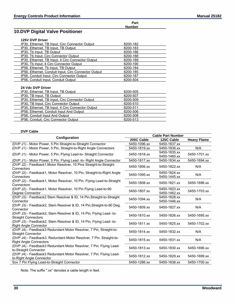
10.DVP Digital Valve Positioner 125V DVP Driver IP30, Ethernet, TB Input, Circ Connector Output 8200-182 IP30, Ethernet, TB Input, TB Output 8200-183 IP30, Tb Input, TB Output 8200-186 IP30, Tb Input, Circ Connector Output 8200-188 IP30, Ethernet, TB Input, 4 Circ Connector Output 8200-189 IP30, Tb Input, 4 Circ Connector Output 8200-190 IP56, Ethernet, Tb Input, TB Output 8200-184 IP56, Ethernet, Conduit Input, Circ Connector Output 8200-185 IP56, Conduit Input, Circ Connector Output 8200-187 IP56, Conduit Input, Conduit Output 8200-504 24 Vdc DVP Driver IP30, Ethernet, TB Input, TB Output 8200-505 IP30, TB Input, TB Output 8200-507 IP30, Ethernet, TB Input, Circ Connector Output 8200-509 IP30, TB Input, Circ Connector Output 8200-510 IP30, Ethernet, TB Input, 4 Circ Connector Output 8200-511 IP56, Ethernet, Conduit Input And Output 8200-506 IP56, Conduit Input And Output 8200-508 IP56, Conduit, Circ Connector Output 8200-513 DVP Cable
Configuration Cable Part Number
200C Cable 125C Cable Heavy Flame(DVP J1) - Motor Power, 5 Pin Straight-to-Straight Connector 5450-1096.xx 5450-1837.xx (DVP J1) - Motor Power, 5 Pin, Straight-to-Right Angle Connectors 5450-1819.xx 5450-1836.xx N/A
(DVP J1) - Motor Power, 5 Pin, Flying Lead-to- Straight Connector 5450-1818.xx 5450-1835.xx 5450-1460.xx
5450-1701.xx
(DVP J1) - Motor Power, 5 Pin, Flying Lead -to- Right Angle Connector 5450-1817.xx 5450-1834.xx 5450-1694.xx (DVP J2) - Feedback1,Motor Resolver, 10 Pins Straight-to-Straight Connectors
5450-1806.xx 5450-1822.xx N/A
(DVP J2) - Feedback1, Motor Resolver, 10 Pin, Straight-to-Right Angle Connectors
5450-1095.xx 5450-1824.xx 5450-1445.xx
N/A
(DVP J2) - Feedback1, Motor Resolver, 10 Pin, Flying Lead-to-Straight Connectors
5450-1808.xx 5450-1821.xx 5450-1696.xx
(DVP J2) - Feedback1, Motor Resolver, 10 Pin Flying Lead-to-90 Degree Connector
5450-1807.xx 5450-1823.xx 5450-1462.xx
5450-1703.xx
(DVP J3) - Feedback2 Stem Resolver & ID, 14 Pin,Straight-to-Straight Connector
5450-1094.xx 5450-1828.xx 5450-1446.xx
N/A
(DVP J3) - Feedback2, Stem Resolver & ID, 14 Pin,Straight-to-90 Deg. Connector
5450-1809.xx 5450-1827.xx N/A
(DVP J3) - Feedback2, Stem Resolver & ID, 14 Pin, Flying Lead -to-Straight Connectors
5450-1810.xx 5450-1826.xx 5450-1695.xx
(DVP J3) - Feedback2, Stem Resolver & ID, 14 Pin, Flying Lead -to-Right Angle Connector
5450-1811.xx 5450-1825.xx 5450-1702.xx
(DVP J4) - Feedback3 Redundant Motor Resolver, 7 Pin, Straight-to-Straight Connector
5450-1814.xx 5450-1832.xx N/A
(DVP J4) - Feedback3, Redundant Motor Resolver, 7 Pin, Straight-to-Right Angle Connectors
5450-1815.xx 5450-1831.xx N/A
(DVP J4) - Feedback3 Redundant Motor Resolver, 7 Pin, Flying Lead-to-Straight Connector
5450-1813.xx 5450-1830.xx 5450-1696.xx
(DVP J4) - Feedback3 Redundant Motor Resolver, 7 Pin, Flying Lead-to-Right Angle Connector
5450-1812.xx 5450-1829.xx 5450-1699.xx
Sov 7 Pin Flying Lead-to-Straight Connector 5450-1286.xx 5450-1838.xx 5450-1700.xx Note: The suffix ".xx" denotes a cable length in feet.

Manual 25182 Energy Controls Product Information
Woodward 31
11. Magnetic Pickups
12. Active Proximity Probes

Energy Controls Product Information Manual 25182
32 Woodward
5—Software Licenses Woodward’s Graphical Application Program (GAP™) is used to custom program Woodward’s MicroNet™ and Atlas controllers. The GAP install software may be downloaded from the Woodward website free or copied multiple times, but does not function unless a software license is purchased for each computer (seat) that it is to be used on. Each listed seat license price below includes one seat license (authorization serial number), which can only be used on one computer. GAP Software Programs & Kits Part Number GAP & ABLS Programmer License 8928-810
This seat license is used to authorize the GAP or ABLS on any one computer:
The GAP or ABLS Install Programs must first be downloaded from Woodward's website or from a CD kit onto the desired computer, before the received program authorization serial number can be used to authorize its use on that computer.
An un-activated version of the Monitor-GAP service tool program is also installed on the target computer during a GAP or ABLS program install. This Monitor-GAP service tool program can then be activated/authorized by purchasing a Monitor-GAP license (refer to information listed below).
GAP Programmer 5.XX and higher used on most products except as noted below
GAP Programmer 3.XX programs are used to create and change application programs in AtlasSC, 2300, and 733 controllers
ABLS Programmer 4.XX program is used to create and change application programs in 723 and 828 controllers
The Microsoft C/C++ 6.0 Compiler program is required to code GAP application programs for MicroNet Pentium with NT based operating systems. Please refer to this manual for Microsoft C/C++ 6.0 Compiler pricing.
Software updates are free for each license, and are available by installing the latest version of the respective software program onto the authorized computer.
Woodward’s Monitor-GAP service tool program is also installed during GAP Programmer install program, and can be authorized and utilized with this program
GAP & ABLS Programmer CD Kit (Use WW SW Programs Install CD Kit, 8928-1088)
The WW Software Programs Install CD kit includes the latest GAP or ABLS Install Programs.
These install programs can also be downloaded for free from the Woodward website.
GAP-Read-Only Programmer License (none needed) GAP-Demo Programmer License (none needed)
No license is necessary for the GAP-Read-Only software program functionality. When a GAP Programmer program is installed on a computer without an authorization serial number, the program functions as a Read Only GAP program or as a Demo GAP program.
The GAP Programmer Install Program must first be downloaded from Woodward's website or from a WW Software Programs Install CD onto the desired computer, before it can be used as a Read-Only or Demo based GAP program.
ProTech GAP License / ToolKit Runtime License 8447-5002
This license is used to authorize Woodward’s GAP program (function block programming) on any one computer for use by ProTech users to create and download custom GAP application programs into ProTechTPS, MSM, or SX models.
Not compatible with ProTech-GII models Does not require GAP program to be authorized with license #8928-810 Monitor GAP is not compatible with the ProTechTPS, MSM, or SX models

Manual 25182 Energy Controls Product Information
Woodward 33
GAP Software Programs & Kits Part Number When this is used as a Read Only GAP program, a user can only view the GAP program
and not make program changes.
When this is used as a Demo GAP program, a user can create and make changes to a program, but cannot compile code for use in a control. After 180 days, this program will revert to a Read Only program.
Optionally, the Monitor-GAP service tool program can be authorized and utilized with this program functioning in its Read-Only or Demo modes of operation.
Monitor-GAP License 8928-5007
This license is used to authorize the Monitor-GAP software service tool, and only includes a program authorization serial number for one computer (seat).
Monitor GAP is a licensed software service tool that allows GAP users to view real-time values in GAP application programs when connected to a control, or running NetSim™ tools. Monitor GAP works in parallel with the GAP graphical display and superimposes the actual run-time values into that display environment.
The Monitor GAP program is embedded in GAP Programmer versions 3.05 and higher and GAP Editor 2.14 and higher install programs.
The GAP Programmer Install Program version 3.05 or higher must first be downloaded from Woodward's website or from a CD kit, before the received program authorization serial number can be used to authorize its use.
Users of GAP 2.13 or lower programs must first update their GAP Editor to GAP2.14 or higher before this license can be used.
Monitor GAP is NOT compatible with ProTech TPS, ProTech-MSM, or ProTech-SX devices.
Old GAP Programs (3.03 and older) CD Install Kits XXXX-XXX
This install kit includes a CD Kit with the respective GAP X.XX install program and associated user license.
Old GAP programs are used to create, change, and support older application programs in MicroNet, Atlas, and 733 controllers.
The Microsoft C/C++ 6.0 Compiler program is required to code GAP application programs for MicroNet Pentium or AtlasPC controllers with NT based operating systems. Please refer to this manual for Microsoft C/C++ 6.0 Compiler pricing.
Contact the Woodward technical assistance group for part number availability of Old GAP programs, and associated turbine package models.
Software Service Tool Programs & Kits Part Number Woodward Software Programs Install CD Kit 8928-1088 This install kit includes the following software install programs: (1) GAP Programmer install program (1) ABLS program install program (1) Control Assistant program install program (1) Monitor GAP tool install program (1) NetSim Basic install program (1) Microsoft “.NET” Framework Note: These install programs can also be downloaded for free from the Woodward website.
Energy Controls Product Information Manual 25182
34 Woodward
Control Assistant Software License 8928-5014 This license is used to authorize the Control Assistant Software tool on one computer
(seat).
The Control Assistant program is used to monitor high-speed Datalog files created in Atlas, MicroNet, and MicroNet TMR controllers.
For CPU5200-based MicroNet Plus and Atlas-II, Control Assistant provides the following: o Live parameter monitoring, tuning, and trending o Off-line trending (Datalogs and archived trend data)
Control Assistant Install CD Kit (Use WW SW Programs Install CD Kit, 8928-1088)
The WW Software Programs Install CD kit includes the latest Control Assistant program.
This install program can also be downloaded for free from the Woodward website. Microsoft C/C++ 6.0 Compiler 1796-046
This Install Kit includes a CD Kit with the Microsoft C/C++ 6.0 Compiler but no user License. Customer must obtain a downgradable Microsoft C/C++ Compiler license to legally use this sofware. Licenses are available from Microsoft resellers that offer group licensing.
The Microsoft C/C++ 6.0 Compiler is required to successfully compile Coder 3.0X for MicroNet Pentium, NTCPU, AtlasPC, and older NetSim versions.
ToolKit Developer License 8928-5016 This license is used to authorize the Developer functionality in ToolKit, and only includes a program authorization serial number for one computer (seat).
TookKit is a licensed software development program used to create Service Tools and HMIs (Human–Machine Interface) for Woodward electronic controllers 2300, 723, 733, Atlas, and MicroNets via Woodward’s Servlink protocol over RS-232/-422/-485 serial, CANopen, Ethernet, or telephone-line connections.
Upon purchasing the Developer license, you will be given a serial number. It is important for you to keep this number, as it is your proof that you own the license.
828 Application Programs CD Kit 8928-1077
This CD Kit includes (8) eight 828 application programs based software programs and a LON binding kit for use by distribution and or RTRs.
The following programs are included: 828 GAP Application Prg – STD PGEN, DSLC Loadshare 828 GAP Application Prg – STD Marine, SE-Propulsion, Low Speed 828 GAP Application Prg – STD Marine, SE-Propulsion 828 GAP Application Prg – STD PGEN, DSLC Loadshare, Low Speed 828 GAP Application Prg – STD Marine, Mech Loadshare, Low Speed 828 GAP Application Prg – STD Marine, Mech Loadshare 828 GAP Application Prg – STD Industrial Process Control (424) 828 GAP Application Prg – STD Industrial Process Control (598)

Manual 25182 Energy Controls Product Information
Woodward 35
Software Service Tool Programs & Kits Part Number NetSim Basic License 8928-5005
This seat license is used to authorize a NetSim Basic software program, and only includes a program authorization serial number for one computer (seat).
The NetSim Control Executive program must first be downloaded from Woodward's website onto the desired computer before the received program authorization serial number can be used to authorize its use on that computer.
NetSim Basic is a Simulation Service tool that allows GAP application programs to be run and tested on a computer before they are downloaded into the control. With NetSim Basic, once a GAP application program has been created it can then be executed to simulate the open-loop control operation. Training is available to utilize GAP-to-GAP modeling techniques to achieve closed-loop control operations with NetSim Basic.
The supported hardware platforms are MicroNet, MicroNet TMR, Atlas, and 2301D controllers.
Either the Microsoft Visual C++ 2008 Express Edition Compiler or the Microsoft C/C++ 6.0 Compiler program is required to operate NetSim Basic program on a computer. The Visual C++ 2008 Express Edition is available from the Microsoft download site.
The NetSim Basic program is only compatible with GAP programs using Coder 2.08 and higher Coder programs.
Contact the Woodward technical assistance group for training.
NetSim Advanced License 8928-5006
This seat license is used to authorize a NetSim Advanced software program, and only includes a program authorization serial number for one computer (seat).
The NetSim Control Executive program must first be downloaded from Woodward's website onto the desired computer before the received program authorization serial number can be used to authorize its use on that computer.
The NetSim Advanced program is a Simulation Service tool that allows GAP application programs to be run and tested against turbine models on a computer before they are downloaded into the control. With NetSim Advanced, once a GAP application program has been created it can then be executed against a simulated turbine package to simulate the closed-loop control operation.
The supported hardware platforms are MicroNet, MicroNet TMR, Atlas, and 2301D controllers.
Either the Microsoft Visual C++ 2008 Express Edition Compiler or the Microsoft C/C++ 6.0 Compiler program is required to operate NetSim Basic program on a computer. The Visual C++ 2008 Express Edition is available from the Microsoft download site.
The NetSim Advanced program is only compatible with GAP programs using Coder 2.08 and higher Coder programs.
Contact the Woodward technical assistance group for training. Software Service Tool Programs & Kits Part Number AppManager Datalog Retrieval License - Enterprise 8928-5009
This license is used to authorize the AppManager Program’s Datalog Retrieval Function for 4 or more controls, and only includes a program authorization serial number for one computer (seat).
Datalog Retrieval Function for 1-3 controls is included in AppManager without fee.
The AppManager Program’s Datalog Retrieval Function is embedded in AppManager Version 2.2 and higher install programs.
The AppManager Install Program must be downloaded from Woodward's website or from the respective control’s service tool software directory, and onto the desired computer, before the received program authorization serial number can be used to authorize its use on that computer.
The Datalog Retrieval functionality once enabled in AppManager performs automatic archiving of Datalog files generated on one or more controls connected by a network. The collected files are given unique names based upon the original file name, the last time of modification, and the source control.

Energy Controls Product Information Manual 25182
36 Woodward
Auxiliary Devices USB to Serial Adapter Kit 8928-463 (Includes USB to 9 Pin Sub-D converter, 6 foot Serial Cable, & Software driver Installation CD) Allows USB ports to communicate to Woodward products (SPCs, 2301Ds, AtlasSCs, etc.) via serial communications. MicroNet TMR Programmer (PCMCIA Flash Card) 1790-9026 4 MB Flash Memory Card 1790-789 10 MB Flash Memory Card 1790-792
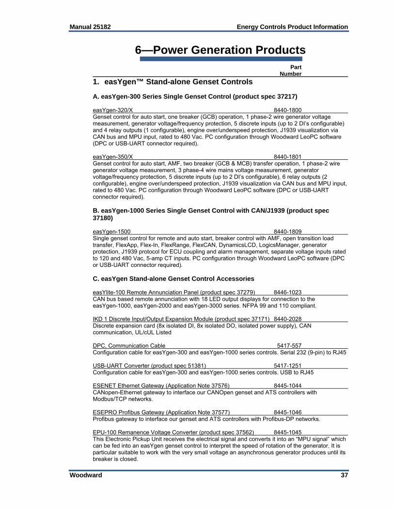
Manual 25182 Energy Controls Product Information
Woodward 37
6—Power Generation Products Part Number
1. easYgen™ Stand-alone Genset Controls A. easYgen-300 Series Single Genset Control (product spec 37217) easYgen-320/X 8440-1800 Genset control for auto start, one breaker (GCB) operation, 1 phase-2 wire generator voltage measurement, generator voltage/frequency protection, 5 discrete inputs (up to 2 DI’s configurable) and 4 relay outputs (1 configurable), engine over/underspeed protection, J1939 visualization via CAN bus and MPU input, rated to 480 Vac. PC configuration through Woodward LeoPC software (DPC or USB-UART connector required). easYgen-350/X 8440-1801 Genset control for auto start, AMF, two breaker (GCB & MCB) transfer operation, 1 phase-2 wire generator voltage measurement, 3 phase-4 wire mains voltage measurement, generator voltage/frequency protection, 5 discrete inputs (up to 2 DI’s configurable), 6 relay outputs (2 configurable), engine over/underspeed protection, J1939 visualization via CAN bus and MPU input, rated to 480 Vac. PC configuration through Woodward LeoPC software (DPC or USB-UART connector required). B. easYgen-1000 Series Single Genset Control with CAN/J1939 (product spec 37180) easYgen-1500 8440-1809 Single genset control for remote and auto start, breaker control with AMF, open transition load transfer, FlexApp, Flex-In, FlexRange, FlexCAN, DynamicsLCD, LogicsManager, generator protection, J1939 protocol for ECU coupling and alarm management, separate voltage inputs rated to 120 and 480 Vac, 5-amp CT inputs. PC configuration through Woodward LeoPC software (DPC or USB-UART connector required). C. easYgen Stand-alone Genset Control Accessories easYlite-100 Remote Annunciation Panel (product spec 37279) 8446-1023 CAN bus based remote annunciation with 18 LED output displays for connection to the easYgen-1000, easYgen-2000 and easYgen-3000 series. NFPA 99 and 110 compliant. IKD 1 Discrete Input/Output Expansion Module (product spec 37171) 8440-2028 Discrete expansion card (8x isolated DI, 8x isolated DO, isolated power supply), CAN communication, UL/cUL Listed DPC, Communication Cable 5417-557 Configuration cable for easYgen-300 and easYgen-1000 series controls. Serial 232 (9-pin) to RJ45 USB-UART Converter (product spec 51381) 5417-1251 Configuration cable for easYgen-300 and easYgen-1000 series controls. USB to RJ45 ESENET Ethernet Gateway (Application Note 37576) 8445-1044 CANopen-Ethernet gateway to interface our CANOpen genset and ATS controllers with Modbus/TCP networks. ESEPRO Profibus Gateway (Application Note 37577) 8445-1046 Profibus gateway to interface our genset and ATS controllers with Profibus-DP networks. EPU-100 Remanence Voltage Converter (product spec 37562) 8445-1045 This Electronic Pickup Unit receives the electrical signal and converts it into an “MPU signal” which can be fed into an easYgen genset control to interpret the speed of rotation of the generator. It is particular suitable to work with the very small voltage an asynchronous generator produces until its breaker is closed.
Energy Controls Product Information Manual 25182
38 Woodward
Part Number NETBITER Remote Communications Gateway (Application Note : HMSI-27-214) The Netbiter EasyConnect 250 Gateway connects with easYgen controls through RS-485 Modbus interface and enables to provide remote communication through cloud connection. It is sold and supported through HMS sales network. CAN Fiber Optic Communmication Gateway (Application Note 37598) 8445-1049 CAN Open Fiber Optic Gateway to interface our CANOPEN genset and ATS for enabling long distance communication.
2. easYgen™ Paralleling Genset Controls A. easYgen-2000 Series Paralleling Genset Control (product spec 37448) Paralleling genset controls for 1 unit to utility, or up to 16 units in island operation. Remote and auto start, load sharing with load-dependent start/stop, synchronization breaker control with AMF, open/closed transition load transfer, soft loading, interchange. Generator, engine, and mains protection. Integrated LogicsManager Boolean programming provides flexibility for a wide range of applications and operating modes. Induction generator compatible. Separate voltage inputs rated to 120 and 480 Vac. PC configuration through Woodward ToolKit software (DPC or USB-UART connector required). 1-amp or 5-amp CT input versions available. easYgen-2200 Package 1 (MPU input) 8440-1855 Speed measurement via magnetic pickup, 1 analog output. 5-amp CT inputs. easYgen-2200 Package 2 (ECU input) 8440-1857 Features of easYgen-2200/P1 but with CAN/J1939 for speed control (no MPU). 5-amp CT inputs. easYgen-2300 Package 1 8440-2080 Speed measurement via frequency measurement, 2 analog outputs, 5-amp CT inputs; UL/cUL pending. easYgen-2300 Package 2 (ECU input) 8440-2058 Features of easYgen-2300/P1 but with CAN/J1939 for speed control (no MPU), 2 analog outputs, 5-amp CT inputs; UL/cUL pending. easYgen-2500 Package 1 (MPU or ECU input, RS-485 Modbus) 8440-1884 Speed measurement via magnetic pickup. CAN/J1939 for speed control. RS-485 Modbus RTU, 4 analog outputs. 5-amp CT inputs. B. easYgen-2000 Series Rental Genset Control (product spec 37543) easYgen-2500 Rental Package (MPU or ECU input, RS-485 Modbus) 8440-2029 Complete feature set of the easYgen-2500 Package 1 plus added functionality for rental genset applications, including (4) switchable parameter sets to change rated values for system frequency, engine speed, generator voltage, mains/busbar voltage, generator real and reactive power and generator current, as well as control setpoints for voltage, frequency, load and power factor. 2-breaker control (GCB, MCB). 5 amp CT inputs. C. easYgen-2000 Series Asynchronous Genset Control (product spec 37568) Asynchron Kit 2000 8923-2074 Complete feature set of the easYgen-2500 Package 1 plus a remanence voltage converter (EPU-100). Manual#37561 describes the application note for asynchronous use.

Manual 25182 Energy Controls Product Information
Woodward 39
Part Number D. easYgen-3000 Series Paralleling Genset Control (product spec 37258) Paralleling genset controls for up to 32 units in isolated or utility parallel operation. Remote and auto start, load sharing with load-dependent start/stop, synchronization breaker control with AMF, open/closed transition load transfer, soft loading, interchange. Generator, engine, and mains protection. Display and evaluation of (100) common J1939 analog values. Integrated LogicsManager Boolean programming provides flexibility for a wide range of applications and operating modes. Induction generator compatible. Separate voltage inputs rated to 120 and 480 Vac. PC configuration through Woodward ToolKit software. 1-amp or 5-amp CT input versions available. Door mount (with 5.7” color display) or back panel mount (aluminum housing, no display) versions available. easYgen-3200 Package 1 8440-2050 Door mount, standard I/O set. 5 amp CT inputs. easYgen-3200 Package 2 (cogeneration version) 8440-2052 Complete feature set of the easYgen-3200 Package 1 plus added functionality for gaseous-fuel engines and cogeneration (heat and power) applications, including 3 freely-configurable internal PID controllers and I/O expansion capability over CAN communication (discrete and/or analog I/O may be added through external modules and used for monitoring and control). 5-amp CT inputs. easYgen-3100 Package 1 8440-2054 Back panel mount, standard I/O set. 5 amp CT inputs. easYgen-3100 Package 2 (cogeneration version) 8440-2056 Complete feature set of the easYgen-3100 Package 1 plus added functionality for gaseous-fuel engines and cogeneration (heat and power) applications, including 3 freely-configurable internal PID controllers and I/O expansion capability over CAN communication (discrete and/or analog I/O may be added through external modules and used for monitoring and control). 5-amp CT inputs. E. easYgen-3000 Series for Complex Breaker Applications (product specification 37523) easYgen-3500 Package 1 8440-1934 Complete feature set of the easYgen-3200 Package 1 plus added functionality for complex distribution system applications with multiple utility feeds and/or tie breakers, including 3-breaker control (GCB, GGB (generator group breaker), MCB) and connectivity with up to (16) LS-5 circuit breaker controllers. Door mount, standard I/O set. 5 amp CT inputs. easYgen-3500 Package 2 8440-1936 Complete feature set of the easYgen-3500 Package 1 plus additional 10 digital outputs, 11 digital monitoring inputs, 2 sinking output (kVArh & kWh pulses), 3 analogous 0/4-20mA outputs, 7 analogous inputs, Door mount, standard I/O set. 5 amp CT inputs. easYgen-3400 Package 1 8440-1945 Complete feature set of the easYgen-3100 Package 1 plus added functionality for complex distribution system applications with multiple utility feeds and/or tie breakers, including 3-breaker control (GCB, GGB (generator group breaker), MCB) and connectivity with up to (16) LS-5 circuit breaker controllers. Back panel mount, standard I/O set. 5 amp CT inputs. easYgen-3400 Package 2 8440-2078 Complete feature set of the easYgen-3400 Package 1 plus additional 10 digital outputs, 11 digital monitoring inputs, 2 sinking output (kVArh & kWh pulses), 3 analog 0/4-20mA outputs, 7 analog inputs.

Energy Controls Product Information Manual 25182
40 Woodward
Part Number F. easYgen-3000 Series for Complex Breaker Applications - Marine Version (product spec 37533) easYgen-3500 Marine Package 8440-2047 Complete feature set of the easYgen-3500 Package 1 plus added functionality for marine applications, including redundant GCB monitoring and visualization of countdown timers on display. DNV, Lloyd’s Register, ABS, GL, and BV type approvals. Door mount, standard I/O set. 5 amp CT inputs. easYgen-3400 Marine Package 8440-2045 Complete feature set of the easYgen-3400 Package 1 plus added functionality for marine applications, including dual-redundant GCB monitoring. DNV, Lloyd’s Register, ABS, GL, and BV type approvals. Back panel mount, standard I/O set. 5 amp CT inputs. G. easYgen-3000 Series Rental Genset Control (product spec 37544) easYgen-3500 Rental Package 8440-2030 Base feature set of the easYgen-3500 Package 1 plus added functionality for rental genset applications, including (4) switchable parameter sets to change rated values for system frequency, engine speed, generator voltage, mains voltage, busbar voltage, generator real and reactive power and generator current, as well as control setpoints for voltage, frequency, load and power factor. 3-breaker control (GCB, GGB (generator group breaker), MCB). 5-amp CT inputs. Note- not compatible with the LS-5 circuit breaker control. easYgen-3400 Rental Package 8440-2163 Base feature set of the easYgen-3400 Package 1 plus added functionality for rental genset applications, including (4) switchable parameter sets to change rated values for system frequency, engine speed, generator voltage, mains voltage, busbar voltage, generator real and reactive power and generator current, as well as control setpoints for voltage, frequency, load and power factor. 3-breaker control (GCB, GGB (generator group breaker), MCB). 5-amp CT inputs. Note- not compatible with the LS-5 circuit breaker control. H. easYgen-3000 Series Asynchronous Genset Control (product spec 37568) Asynchron Kit 3000 8923-2073 Complete feature set of the easYgen-3500 Package 2 plus a remanence voltage converter (EPU-100). Manual#37561 describes the application note for asynchronous use. I. easYgen Paralleling Genset Control Accessories RP-3000 Remote Control Panel (product spec 37446) 8446-1048 Remote control and annunciation panel for use with either the back-panel mounted easYgen-3100 or door-mounted easYgen-3200 generator controls (limit of one remote panel per easYgen controller). Allows remote control, remote visualization (including synch-scope) and password-protected remote configuration. Allows manual operation of easYgen-3100 controls. CAN communication. Color LCD. RP-3000 Remote Control Panel – Marine Version (product spec 37446) 8446-1046 Complete feature set of the RP-3000 for marine applications, for use with the easYgen-3400/3500 marine package genset controllers. DNV, Lloyd’s Register, ABS, GL, and BV type approvals. RP-3000 Remote Control Panel – Rental Version (product spec 37446) 8446-1059 Complete feature set of the RP-3000 for marine applications, for use with the easYgen-3400 rental package genset controllers. Note: Not compatible with the easYgen-3500 rental package.

Manual 25182 Energy Controls Product Information
Woodward 41
Part Number easYlite-100 Remote Annunciation Panel (product spec 37279) 8446-1023 CAN bus based remote annunciation with 18 LED output displays for connection to the easYgen-2000 and easYgen-3000 series. NFPA 99 and 110 compliant. LS-5 Circuit Breaker Control (product spec 37522) Utility/bus tie breaker control with synchronization for easYgen-3400/3500, soft load/unload, protection and decoupling features. CAN communication for connection of up to (32) easYgen-3500 or easYgen-3400 models, plus up to (16) LS-5 controls for complex system control. Up to (32) bus segments can be defined. True RMS 3-Phase voltage and current measurement, user-defined monitoring limits and Modbus RS-485 communication allow the LS-5 to be used independently for relaying in PLC-based systems. Separate voltage inputs rated to 120 and 480 Vac. PC configuration through Woodward ToolKit software (DPC or USB-UART connector required). 1-amp or 5-amp CT input versions available. Door mount (with display) or back panel mount (aluminum housing, no display) versions available. LS-521 8440-1947 Door mounted version with display. Auto and manual operation. 5 amp CT inputs. LS-511 8440-1946 Back-panel mounted version with aluminum housing (no display). Includes (8) programmable LED’s for annunciation with customizable paper strip, ready-for-operation LED and lamp test button. 5 amp CT inputs. LS-5 Circuit Breaker Control - Marine Version (product spec 37545) Complete feature set of the LS-5, with DNV Certification for marine applications. LS-521 Marine Package 8440-2075 Door mounted version with display. Auto and manual operation. 5 amp CT inputs. DNV, Lloyd’s Register, ABS, GL, and BV type approvals. LS-511 Marine Package 8440-2077 Back-panel mounted version with aluminum housing (no display). Includes (8) programmable LED’s for annunciation with customizable paper strip, ready-for-operation LED and lamp test button. 5 amp CT inputs. DNV, Lloyd’s Register, ABS, GL, and BV type approvals. PowerGen Learning Module (Product Spec 03421) 8447-1012 The Power Generation Learning Module provides the student with an interactive learning environment that covers Power Generation and Power Generation control Modes. Fundamentals of speed controls and the dynamic tuning of a PID (proportional, Integral, Derivative) type speed control algorithm are also included. Note: this is a learning tool and not a simulation/virtual; prototyping tool. LSG Load Share Gateway Analog/RS-485 (product spec 37451) LSG (real [kw] load sharing) 8444-1075 Provides real and reactive power load sharing from easYgen paralleling genset controls with GCP-30 and EGCP-2 generator controls over RS-485, or real power only load sharing with legacy controls through a configurable analog bias signal. LSG (reactive [kVAR] load sharing) 8444-1074 Provides reactive power load sharing from easYgen paralleling genset controls with legacy controls through a configurable analog bias signal. DPC Communication Cable 5417-557 Configuration cable for easYgen-2000 series controls and LS-5 circuit breaker controls. Serial 232 (9-pin) to RJ45. USB-UART Converter (product spec 51381) 5417-1251 Configuration cable for easYgen-2000 series controls and LS-5 circuit breaker controls. USB to RJ45. Part

Energy Controls Product Information Manual 25182
42 Woodward
Number IKD 1 Discrete Input/Output Expansion Module (product spec 37171) 8440-2028 Discrete expansion card (8x isolated DI, 8x isolated DO, isolated power supply), CAN communication. ESENET Ethernet Gateway (Application Note 37576) 8445-1044 CANopen-Ethernet gateway to interface our CANOpen genset and ATS controllers with Modbus/TCP networks. ESEPRO Profibus Gateway (Application Note 37577) 8445-1046 Profibus gateway to interface our genset and ATS controllers with Profibus-DP networks. EPU-100 Remanence Voltage Converter (product spec 37562) 8445-1045 This Electronic Pickup Unit receives the electrical signal and converts it into an “MPU signal” which can be fed into an easYgen genset control to interpret the speed of rotation of the generator. It is particular suitable to work with the very small voltage an asynchronous generator produces until its breaker is closed. ActiVgen Engine Speed Control (product spec 03419) 8440-2100 Used as a separate, external primary speed control with user-configurable PID settings. Gives the user full access to tune the Caterpillar engine directly. CAN Fiber Optic Communmication Gateway (Application Note 37598) 8445-1049 CAN Open Fiber Optic Gateway to interface our CANOPEN genset and ATS for enabling long distance communication. NETBITER Remote Communications Gateway (Application Note : HMSI-27-214) The Netbiter EasyConnect 250 Gateway connects with easYgen controls through RS-485 Modbus interface and enables to provide remote communication through cloud connection. It is sold and supported through HMS sales network. Thermocouple Scanner (Axiomatic Product Spec: TDAXTC20) The thermocouple scanner monitors up to 20 thermocouples and provides the temperature information to the engine control system over SAE J1939 CAN bus. It is sold and supported through Axiomatic Technology Corporation sales network.
3. EGCP-2 Generator Controls A. EGCP-2 Series (product spec 03219) EGCP-2 High Voltage (150-300 Vac) 8406-120 Paralleling genset control for up to 8 units, remote start, synchronization, generator/engine protection, load/var sharing, automatic sequencing, Modbus communication interfaces. High-voltage version (150–300 Vac PT sensing range). EGCP-2 Low Voltage (50-150 Vac) 8406-121 Paralleling genset control for up to 8 units, remote start, synchronization, generator/engine protection, load/var sharing, automatic sequencing, Modbus communication interfaces. Low-voltage version (50–150 Vac PT sensing range). B. EGCP-2 Generator Control Accessories Conversion Cable 5417-551 Cable allows PC configuration of EGCP-2 series controls, converts RS-422 to RS-232. Connector Kit 8928-301 Wiring harness connector kit, required for connection to each EGCP-2 controller. LSG Load Share Gateway Analog/RS-485 (product spec 37451) LSG (real [kw] load sharing) 8444-1075 Provides real and reactive power load sharing from easYgen paralleling genset controls with EGCP-2 generator controls over RS-485.
Manual 25182 Energy Controls Product Information
Woodward 43
Part Number
4. Switchgear Controls A. DTSC-200 Series Automatic Transfer Switch Control (product spec 37398) DTSC-200, 120 & 480 Vac 8440-1868 For open, delayed or closed transfer using circuit breakers or latching contactors. In-phase monitoring (synch check) can be enabled for all transfer modes. Selectable applications: Main- Gen, Gen-Gen or Main-Main. LogicsManager programmable Boolean logic functions allow for complex transfer schemes without using external relay logic or a separate PLC. Transfer inhibit, extended parallel, source selection, load shed/restore, elevator pre-signal features are all standard. Expandable discrete I/O, PC and front face programmability (password protected), CANopen and RS-485 Modbus communication. Separate 120 and 480 Vac voltage inputs. 1-amp or 5-amp CT input versions available. B. DTSC-50 Series Automatic Transfer Switch Control (product spec 37455) DTSC-50, 50-480 Vac 8440-1894 For open transfer using contactors. Three-phase voltage and frequency measurement for mains and generator, auto or manual operation. Seven-segment display gives voltage, frequency, alarm codes, engine hours and number of transfers. Freely configurable inputs/outputs. Breaker open/close monitoring eliminates the need for external interlock relays. Engine start/cool-down, maintenance counter. 50-480 Vac rated voltage. PC and front face programmability. C. LS-5 Circuit Breaker Control (product spec 37522) Utility/bus tie breaker control with synchronization, soft load/unload, protection and decoupling features. CAN communication for connection of up to (32) easYgen-3500 or easYgen-3400 models, plus up to (16) LS-5 controls for complex system control. Up to (32) bus segments can be defined. True RMS 3-Phase voltage and current measurement, user-defined monitoring limits and Modbus RS-485 communication allow the LS-5 to be used independently for relaying in PLC-based systems. Separate voltage inputs rated to 120 and 480 Vac. PC configuration through Woodward ToolKit software (DPC or USB-UART connector required). 1-amp or 5-amp CT input versions available. Door mount (with display) or back panel mount (aluminum housing, no display) versions available. LS-521 8440-1947 Door mounted version with display. Auto and manual operation. 5 amp CT inputs. LS-511 8440-1946 Back-panel mounted version with aluminum housing (no display). Includes (8) programmable LED’s for annunciation with customizable paper strip, ready-for-operation LED and lamp test button. 5 amp CT inputs. D. LS-5 Circuit Breaker Control - Marine Version (product spec 37545) Complete feature set of the LS-5, with DNV, Lloyd’s Register, ABS, GL, and BV type approvals for marine applications. LS-521 Marine Package 8440-2075 Door mounted version with display. Auto and manual operation. 5 amp CT inputs. DNV, Lloyd’s Register, ABS, GL, and BV type approvals. LS-511 Marine Package 8440-2077 Back-panel mounted version with aluminum housing (no display). Includes (8) programmable LED’s for annunciation with customizable paper strip, ready-for-operation LED and lamp test button. 5 amp CT inputs. DNV, Lloyd’s Register, ABS, GL, and BV type approvals.

Energy Controls Product Information Manual 25182
44 Woodward
Part Number E. Switchgear Controls Accessories LS-511 DIN-Rail Mounting Accessory Bracket 8923-1746 Bracket and screw kit for mounting the LS-511 to standard DIN rails. IKD 1 Discrete Input/Output Expansion Module (product spec 37171 8440-2028 Discrete expansion card (8x isolated DI, 8x isolated DO, isolated power supply), CAN communication DPC Communication Cable 5417-557 Configuration cable for DTSC transfer switch controls and LS-5 circuit breaker controls. Serial 232 (9-pin) to RJ45. USB-UART Converter (product spec 51381) 5417-1251 Configuration cable for DTSC transfer switch controls and LS-5 circuit breaker controls. USB to RJ45. ESENET Ethernet Gateway (Application Note 37576) 8445-1044 CANopen-Ethernet gateway to interface our CANOpen genset and ATS controllers with Modbus/TCP networks. ESEPRO Profibus Gateway (Application Note 37577) 8445-1046 Profibus gateway to interface our genset and ATS controllers with Profibus-DP networks. NETBITER Remote Communications Gateway (Application Note : HMSI-27-214) The Netbiter EasyConnect 250 Gateway connects with easYgen controls through RS-485 Modbus interface and enables to provide remote communication through cloud connection. It is sold and supported through HMS sales network. CAN Fiber Optic Communmication Gateway (Application Note 37598) 8445-1049 CAN Open Fiber Optic Gateway to interface our CANOPEN genset and ATS for enabling long distance communication.
5. Synchronizers A. SPM-A Analog Synchronizer (product spec 82383) SPM-A, Analog Speed & Phase Synchronizer, no voltage matching 9907-028 SPM-A, Analog Speed & Phase Synchronizer, 1% voltage matching 9907-029 SPM-A, Analog Speed & Phase Synchronizer, 5% voltage matching 9905-003 B. SPM-D10 Digital Synchronizer for 1 Breaker, 1-Phase Synch (product spec 37297) SPM-D10, 100 Vac 5448-890 SPM-D10, 400 Vac 8440-1019 Synchronizer for 1 breaker, discrete raise/lower for speed & voltage bias SPM-D10/N, 100 Vac 8440-1432 SPM-D10/N, 400 Vac 8440-1433 Synchronizer for 1 breaker, discrete raise/lower for speed & voltage bias, wide-range power supply (90-265 Vac/dc) SPM-D10/X, 100 Vac 5448-893 SPM-D10/X, 400 Vac 8440-1301 Synchronizer for 1 breaker, analog outputs for speed & voltage bias
Manual 25182 Energy Controls Product Information
Woodward 45
Part Number SPM-D10/XN, 100 Vac 8440-1667 SPM-D10/XN, 400 Vac 8440-1668 Synchronizer for 1 breaker, analog outputs for speed & voltage bias, wide-range power supply (90-265 Vac/dc) C. SPM-D10 Digital Synchronizer for 1 Breaker, 3-Phase Synch (product spec 37298) SPM-D10/YB, 100 Vac 5448-906 SPM-D10/YB, 400 Vac 8440-1021 Synchronizer for 1 breaker (3-phase voltage measurement), discrete raise/lower for speed & voltage bias SPM-D10/NYB, 100 Vac 8440-1434 SPM-D10/NYB, 400 Vac 8440-1435 Features of SPM-D10/YB + wide-range power supply (90-250 Vac/dc) D. SPM-D11 Digital Synchronizer for 1 Breaker, 3-Phase Synch, Load Control (product spec 37292) SPM-D11/LSXR, 12/24 V, 100 Vac 8440-1706 SPM-D11/LSXR, 12/24 V, 400 Vac 8440-1666 Synchronizer for 1 breaker with power control and analog power/var sharing, 3 alarm and 3 signaling relays, analog outputs for speed & voltage bias E. Synchronizer Accessories DPC Communication Cable 5417-557 Configuration cable for SPM-D Synchronizers. Serial 232 (9-pin) to RJ45 USB-UART Converter (product spec 51381) 5417-1251 Configuration cable for SPM-D Synchronizers. USB to RJ45
6. Load Share Controls A. Analog Load Sharing Modules (product specification 82686) LSM, ±3 Vdc bias output 9907-173 Load sharing module with isochronous and droop load-sharing capability, 115/230 Vac power input, ±3 Vdc bias output LSM, CAT PWM bias output (replaces 9907-175) 9907-838 Load sharing module with isochronous and droop load-sharing capability, 24 Vdc power input, Caterpillar PWM bias output LSM, 0.5 to 4.5 Vdc bias output 9907-252 Load sharing module with isochronous and droop load-sharing capability, 24 Vdc power input, 0.5-4.5 Vdc bias output

Energy Controls Product Information Manual 25182
46 Woodward
Part Number B. DSLC-2 Digital Load Share Control (product specification 37493) DSLC-2 8440-1878 Paralleling genset control for up to 32 units in isolated or mains parallel operation combining synchronizer, load sensor, load control, dead bus closing system, VAR, power factor and process control. Dedicated Ethernet port for communications between DSLC-2 and MSLC-2 units. Second Ethernet port for remote control and monitoring using Modbus TCP, allowing DCS and PLC interfacing. Redundant Ethernet communication enabled. Modbus RTU is available through a separate RS-485 port. PC programming using Woodward Toolkit software. Separate voltage inputs rated to 120 and 480 Vac. 1-amp or 5-amp CT input versions available. C. MSLC-2 Master Load Share Control (product specification 37494) MSLC-2 8440-1877 Synchronizer, load sensor, import/export and power factor control, master process controller. Dedicated Ethernet port for communications between up to 32 DSLC-2 and 16 MSLC-2 units on up to 8 bus segments. Second Ethernet port for remote control and monitoring using Modbus TCP, allowing DCS and PLC interfacing. Redundant Ethernet communication enabled. Modbus RTU is available through a separate RS-485 port. PC programming using Woodward Toolkit software. Separate voltage inputs rated to 120 and 480 Vac. 1-amp or 5-amp CT input versions available. D. DSLC-2 & MSLC-2 Accessories Ethernet Switch 1752-423 Unmanaged rail switch with 8 Fast-Ethernet ports (10/100base- TX). Redundant 24 volt power input, DIN-rail mounted, 0-60 °C operation. Class 1 Div 2 cUL rated. Fiber Optic Switch 1711-1069 Unmanaged Industrial Ethernet Rail Switch, store and forward switching mode, Ethernet (10 Mbit/s) and Fast-Ethernet (100 Mbit/s). 4 x 10/100BASE-TX, TP cable, RJ45 sockets, auto-crossing, auto-negotiation, auto-polarity, 1 x 100BASE-FX, MM cable, SC sockets.
7. Digital Multi-Function Relays A. MFR 300 Multifunction Relay / Measuring Transducer with CANopen / RS-485 Modbus Communication MFR300-11M, 100 Vac / 1 A 8444-1089 MFR300-15M, 100 Vac / 5 A 8444-1090 MFR300-71M, 690 Vac / 1 A 8444-1091 MFR300-75M, 690 Vac / 5 A 8444-1092 MFR300-75M/SU03, 690 Vac / 5 A 8444-1093 MFR300-75M/K28, 690 Vac / 5 A 8444-1094 B. LS-5 Circuit Breaker Control (product spec 37522) True RMS 3-Phase voltage/current measurement, Modbus RS-485 communication. Over/under voltage (27/59), over/under frequency (81 O/U), voltage balance/rotation (47), phase shift (78), ROCOF (81), synch check (25). 3 configurable relay outputs. 8-40 Vdc power. Separate 120 and 480 Vac voltage inputs. PC configuration through Woodward ToolKit software (DPC or USB-UART connector required). 1-amp or 5-amp CT input versions available. LS-511 8440-1946 Back-panel mount with aluminum housing (no display). 8 programmable LED’s for annunciation with customizable paper strip, ready-for-operation LED and lamp test button. 5-amp CT inputs.
Manual 25182 Energy Controls Product Information
Woodward 47
Part Number LS-511 DIN-Rail Mounting Accessory Bracket 8923-1746 Bracket and screw kit for mounting the LS-511 to standard DIN rails. easYprotec Multifunction Relay Measuring transducer with CANopen / Modbus Communication easYprotec-1410-1 8441-1160 easYprotec-1410-7 8441-1161 easYprotec-1510-1 8441-1162 easYprotec-1510-7 8441-1163 C. Multi-Function Relay Accessories DPC Communication Cable 5417-557 Configuration cable for MFR & ESDR series controls. Serial 232 (9-pin) to Serial RJ45 USB-UART Converter (product spec 51381) 5417-1251 Configuration cable for MFR & ESDR series controls. USB to RJ45.
8. Expansion Modules A. IKD 1 Discrete Input/Output Expansion Module (product specification 37171) IKD 1 8440-2028 Discrete expansion card (8x isolated DI, 8x isolated DO, isolated power supply), CAN communication B. Expansion Module Accessories DPC Communication Cable 5417-557 Configuration cable for TUG, UMT, & IKD series controls. Serial 232 (9-pin) to Serial RJ45 USB-UART Converter (product spec 51381) 5417-1251 Configuration cable for TUG, UMT, & IKD series controls. USB to RJ45
9. Accessories and Spare Parts A. Brackets Brackets 8923-1023 Fits SPMD, MFR-13, GW4. Set of two (2 brackets, 2 level adjuster, 4 self-drilling screws, 4 back-plate screws) B. Fixing Clamps Fixing Clamps LR01543 For all APRANORM housing types (one piece). Set of 2. C. Terminal Strip Kits Kit-Plug Set for UMT 1 8923-1027 Kit-Plug Set for GCP-30 8923-1028 Kit-Plug Set for SPM-D 8923-1032 Kit-Plug Set for easYgen-3100, 3200 and 3500 series 8923-1314 Kit-Plug Set for easYgen-3400 series 8928-7371 Kit-Plug Set for LS-511 (back-pan mount) 8928-7336 Kit-Plug Set for easYgen-2200 series and LS-521 (door mount) 8928-7286 Kit-Plug Set for easYgen-2500 series 8928-7297 Kit-Plug Set for easYgen-1000 series 8923-1055

Energy Controls Product Information Manual 25182
48 Woodward
Kit-Plug Set for easYgen-320/X 8923-1157 Kit-Plug Set for easYgen-350/X and DTSC-50 8923-1158 Kit-Plug Set for DTSC-200 8923-1805 Kit-Plug Set for DSLC-2 and MSLC-2 8923-1806

Manual 25182 Energy Controls Product Information
Woodward 49
7—Power Distribution Products
1. HighPROTEC Ordering Codes A. HighPROTEC Ordering Code—MCA4 (product spec DOK-FLY_MCA4-2E) Directional Feeder Protection and Grid Coupling — Current, Voltage, Frequency, Power, Control up to six breakers
MCA4 -2 Version 2 with USB, enhanced communication options and new front plate
Digital Inputs
Binary output relays
Housing Large display
8 7 B2 Yes A 16 13 B2 Yes D
Hardware variant 2 Phase Current 5 A/1 A, Ground Current 5 A/1 A 0 Phase Current 5 A/1 A, Sensitive Ground Current 5 A/1 A 1 Housing and mounting Door mounting A Door mounting 19” (flush mounting) B Communication protocol Without protocol A* Modbus RTU, IEC60870-5-103, DNP3.0 RTU | RS485/terminals B* Modbus TCP, DNP3.0 TCP/UDP | Ethernet 100 MB/RJ45 C* Profibus-DP | optic fiber/ST-connector D* Profibus-DP | RS485/D-SUB E* Modbus RTU, IEC60870-5-103, DNP3.0 RTU | optic fiber/ST-connector F* Modbus RTU, IEC60870-5-103, DNP3.0 RTU | RS485/D-SUB G* IEC61850, Modbus TCP, DNP3.0 TCP/UDP | Ethernet 100MB/RJ45 H* IEC60870-5-103, Modbus RTU, DNP3.0 RTU | RS485/terminals Modbus TCP, DNP3.0 TCP/UDP | Ethernet 100 MB/RJ45
I*
IEC61850, Modbus TCP, DNP3.0 TCP/UDP | Optical Ethernet 100MB/LC duplex connector K* Modbus TCP, DNP3.0 TCP/UDP | Optical Ethernet 100MB/LC duplex connector L* Harsh Environment Option None A Conformal Coating B Available menu languages
Standard English/German/Spanish/Russian/Polish/Portuguese/French * Within every communication option only one communication protocol is usable. Smart view can be used in parallel via the Ethernet interface (RJ45). The parameterizing- and disturbance analyzing software Smart view is included in the delivery of HighPROTEC devices.
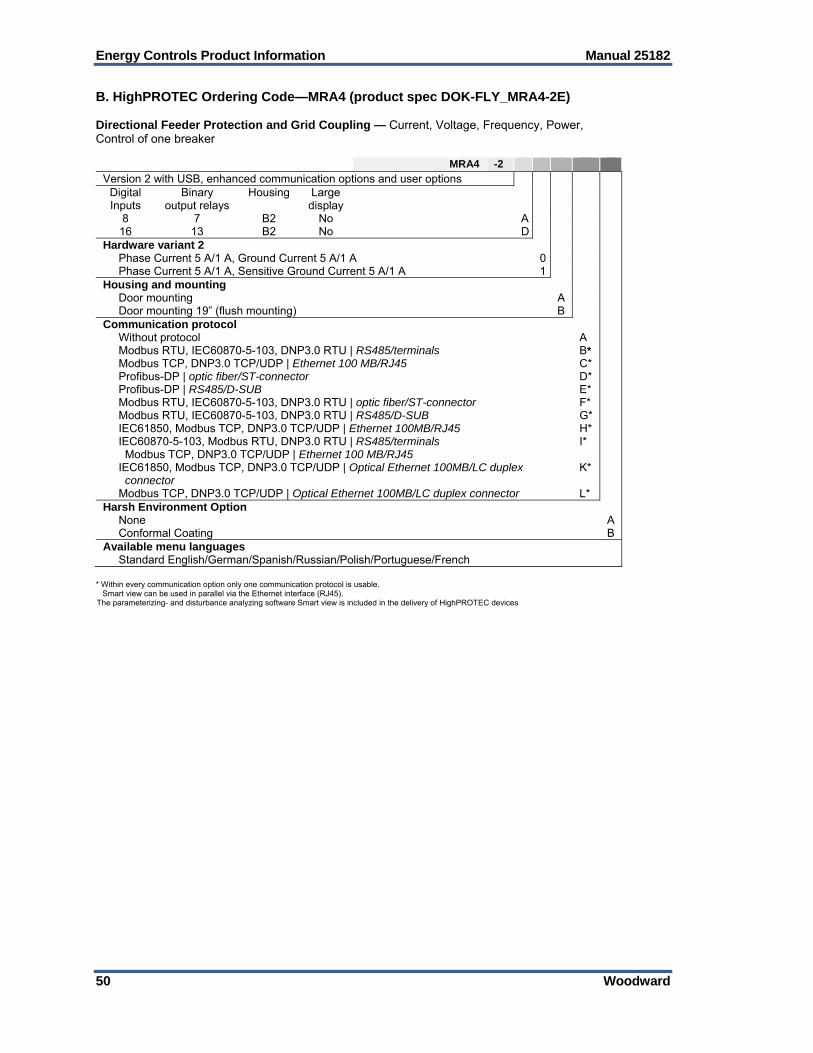
Energy Controls Product Information Manual 25182
50 Woodward
B. HighPROTEC Ordering Code—MRA4 (product spec DOK-FLY_MRA4-2E) Directional Feeder Protection and Grid Coupling — Current, Voltage, Frequency, Power, Control of one breaker
MRA4 -2
Version 2 with USB, enhanced communication options and user options Digital Inputs
Binary output relays
Housing Large display
8 7 B2 No A 16 13 B2 No D
Hardware variant 2 Phase Current 5 A/1 A, Ground Current 5 A/1 A 0 Phase Current 5 A/1 A, Sensitive Ground Current 5 A/1 A 1 Housing and mounting Door mounting A Door mounting 19” (flush mounting) B Communication protocol Without protocol A* Modbus RTU, IEC60870-5-103, DNP3.0 RTU | RS485/terminals B* Modbus TCP, DNP3.0 TCP/UDP | Ethernet 100 MB/RJ45 C* Profibus-DP | optic fiber/ST-connector D* Profibus-DP | RS485/D-SUB E* Modbus RTU, IEC60870-5-103, DNP3.0 RTU | optic fiber/ST-connector F* Modbus RTU, IEC60870-5-103, DNP3.0 RTU | RS485/D-SUB G* IEC61850, Modbus TCP, DNP3.0 TCP/UDP | Ethernet 100MB/RJ45 H* IEC60870-5-103, Modbus RTU, DNP3.0 RTU | RS485/terminals Modbus TCP, DNP3.0 TCP/UDP | Ethernet 100 MB/RJ45
I*
IEC61850, Modbus TCP, DNP3.0 TCP/UDP | Optical Ethernet 100MB/LC duplex connector
K*
Modbus TCP, DNP3.0 TCP/UDP | Optical Ethernet 100MB/LC duplex connector L* Harsh Environment Option None A Conformal Coating B Available menu languages Standard English/German/Spanish/Russian/Polish/Portuguese/French
* Within every communication option only one communication protocol is usable. Smart view can be used in parallel via the Ethernet interface (RJ45).
The parameterizing- and disturbance analyzing software Smart view is included in the delivery of HighPROTEC devices

Manual 25182 Energy Controls Product Information
Woodward 51
C. HighPROTEC Ordering Code—MRI4 (product spec DOK-FLY_MRI4-2E) Non-directional Feeder Protection — Current, Control of one breaker
MRI4 -2 A Version 2 with USB, enhanced communication options and user options Digital Inputs
Binary output relays
Housing Large display
8 6 B1 No Hardware variant 2 Phase Current 5 A/1 A, Ground Current 5 A/1 A 0 Phase Current 5 A/1 A, Sensitive Ground Current 5 A/1 A 1 Housing and mounting Door mounting A Door mounting 19” (flush mounting) B Communication protocol Without protocol A* Modbus RTU, IEC60870-5-103, DNP3.0 RTU | RS485/terminals B* Modbus TCP, DNP3.0 TCP/UDP | Ethernet 100 MB/RJ45 C* Profibus-DP | optic fiber/ST-connector D* Profibus-DP | RS485/D-SUB E* Modbus RTU, IEC60870-5-103, DNP3.0 RTU | optic fiber/ST-connector F* Modbus RTU, IEC60870-5-103, DNP3.0 RTU | RS485/D-SUB G* IEC61850, Modbus TCP, DNP3.0 TCP/UDP | Ethernet 100MB/RJ45 H* IEC60870-5-103, Modbus RTU, DNP3.0 RTU | RS485/terminals Modbus TCP, DNP3.0 TCP/UDP | Ethernet 100 MB/RJ45
I*
IEC61850, Modbus TCP, DNP3.0 TCP/UDP | Optical Ethernet 100MB/LC duplex connector K* Modbus TCP, DNP3.0 TCP/UDP | Optical Ethernet 100MB/LC duplex connector L* Harsh Environment Option None A Conformal Coating B B Available menu languages Standard English/German/Spanish/Russian/Polish/Portuguese/French
* Within every communication option only one communication protocol is usable. Smart view can be used in parallel via the Ethernet interface (RJ45). The parameterizing- and disturbance analyzing software Smart view is included in the delivery of HighPROTEC devices.

Energy Controls Product Information Manual 25182
52 Woodward
D. HighPROTEC Ordering Code—MRU4 (product spec DOK-FLY_MRU4-2E) Voltage and Frequency Protection and Grid Coupling — Control of one breaker
MRU4 -2 A 0 Version 2 with USB, enhanced communication options and user options Digital Inputs
Binary output relays
Housing Large display
8 6 B1 No Hardware variant Standard Housing and mounting Door mounting A Door mounting 19” (flush mounting) B Communication protocol Without protocol A* Modbus RTU, IEC60870-5-103, DNP3.0 RTU | RS485/terminals B* Modbus TCP, DNP3.0 TCP/UDP | Ethernet 100 MB/RJ45 C* Profibus-DP | optic fiber/ST-connector D* Profibus-DP | RS485/D-SUB E* Modbus RTU, IEC60870-5-103, DNP3.0 RTU | optic fiber/ST-connector F* Modbus RTU, IEC60870-5-103, DNP3.0 RTU | RS485/D-SUB G* IEC61850, Modbus TCP, DNP3.0 TCP/UDP | Ethernet 100MB/RJ45 H* IEC60870-5-103, Modbus RTU, DNP3.0 RTU | RS485/terminals Modbus TCP, DNP3.0 TCP/UDP | Ethernet 100 MB/RJ45
I*
IEC61850, Modbus TCP, DNP3.0 TCP/UDP | Optical Ethernet 100MB/LC duplex connector
K*
Modbus TCP, DNP3.0 TCP/UDP | Optical Ethernet 100MB/LC duplex connector L* Harsh Environment Option None A Conformal Coating B Available menu languages Standard English/German/Spanish/Russian/Polish/Portuguese/French
* Within every communication option only one communication protocol is usable. Smart view can be used in parallel via the Ethernet interface (RJ45).
The parameterizing- and disturbance analyzing software Smart view is included in the delivery of HighPROTEC devices

Manual 25182 Energy Controls Product Information
Woodward 53
E. HighPROTEC Ordering Code—MRDT4 (product spec DOK-FLY_MRDT4-2E) Non-directional Transformer Differential Protection — Current Only, Control of one breaker
MRDT4 -2 Version 2 with USB, enhanced communication options and user options
Digital Inputs
Binary output relays
Housing Large display
8 7 B2 No A 16 13 B2 No D
Hardware variants Phase Current 5 A/1 A, W1/W2 Ground Current 5 A/1 A 0 Phase Current 5 A/1 A, W1 Sen. Gr. Curr. 5 A/1 A, W2 Gr. Curr. 5 A/1 A 1 Phase Current 5 A/1 A, W1 Gr. Curr. 5 A/1 A, W2 Sen. Gr. Curr. 5 A/1 A 2 Phase Current 5 A/1 A, W1/W2 Sen. Gr. Curr. 5 A/1 A 3 Housing and mounting Door mounting A Door mounting 19” (flush mounting) B Communication protocol Without protocol A* Modbus RTU, IEC60870-5-103, DNP3.0 RTU | RS485/terminals B* Modbus TCP, DNP3.0 TCP/UDP | Ethernet 100 MB/RJ45 C* Profibus-DP | optic fiber/ST-connector D* Profibus-DP | RS485/D-SUB E* Modbus RTU, IEC60870-5-103, DNP3.0 RTU | optic fiber/ST-connector F* Modbus RTU, IEC60870-5-103, DNP3.0 RTU | RS485/D-SUB G* IEC61850, Modbus TCP, DNP3.0 TCP/UDP | Ethernet 100MB/RJ45 H* IEC60870-5-103, Modbus RTU, DNP3.0 RTU | RS485/terminals Modbus TCP, DNP3.0 TCP/UDP | Ethernet 100 MB/RJ45
I*
IEC61850, Modbus TCP, DNP3.0 TCP/UDP | Optical Ethernet 100MB/LC duplex connector
K*
Modbus TCP, DNP3.0 TCP/UDP | Optical Ethernet 100MB/LC duplex connector L* Harsh Environment Option None A Conformal Coating B Available menu languages Standard English/German/Spanish/Russian/Polish/Portuguese/French
* Within every communication option only one communication protocol is usable. Smart view can be used in parallel via the Ethernet interface (RJ45). The parameterizing- and disturbance analyzing software Smart view is included in the delivery of HighPROTEC devices.

Energy Controls Product Information Manual 25182
54 Woodward
F. HighPROTEC Ordering Code—MCDTV4 (product spec DOK-FLY_MCDTV4-2E) Directional Transformer Differential Protection and Grid Coupling — Current, Voltage, Frequency, Power, Control up to six breakers
MCDTV4 -2 Version 2 with USB, enhanced communication options and user options
Digital Inputs
Binary output relays
Housing Large display
8 7 B2 Yes A 16 13 B2 Yes B
Hardware variant 2 Phase Current 5 A/1 A, Ground Current 5 A/1 A 0 Phase Current 5 A/1 A, W1 Sen. Gr. Curr. 5 A/1 A, W2 Gr. Curr. 5 A/1 A 1 Phase Current 5 A/1 A, W1 Gr. Curr. 5 A/1 A, W2 Sen. Gr. Curr. 5 A/1 A 2 Phase Current 5 A/1 A, W1/W2 Sen. Gr. Curr. 5 A/1 A 3 Housing and mounting Door mounting A Door mounting 19” (flush mounting) B Communication protocol Without protocol A* Modbus RTU, IEC60870-5-103, DNP3.0 RTU | RS485/terminals B* Modbus TCP, DNP3.0 TCP/UDP | Ethernet 100 MB/RJ45 C* Profibus-DP | optic fiber/ST-connector D* Profibus-DP | RS485/D-SUB E* Modbus RTU, IEC60870-5-103, DNP3.0 RTU | optic fiber/ST-connector F* Modbus RTU, IEC60870-5-103, DNP3.0 RTU | RS485/D-SUB G* IEC61850, Modbus TCP, DNP3.0 TCP/UDP | Ethernet 100MB/RJ45 H* IEC60870-5-103, Modbus RTU, DNP3.0 RTU | RS485/terminals Modbus TCP, DNP3.0 TCP/UDP | Ethernet 100 MB/RJ45
I*
IEC61850, Modbus TCP, DNP3.0 TCP/UDP | Optical Ethernet 100MB/LC duplex connector K* Modbus TCP, DNP3.0 TCP/UDP | Optical Ethernet 100MB/LC duplex connector L* Harsh Environment Option None A Conformal Coating B Available menu languages Standard English/German/Spanish/Russian/Polish/Portuguese/French
* Within every communication option only one communication protocol is usable. Smart view can be used in parallel via the Ethernet interface (RJ45). The parameterizing- and disturbance analyzing software Smart view is included in the delivery of HighPROTEC devices.
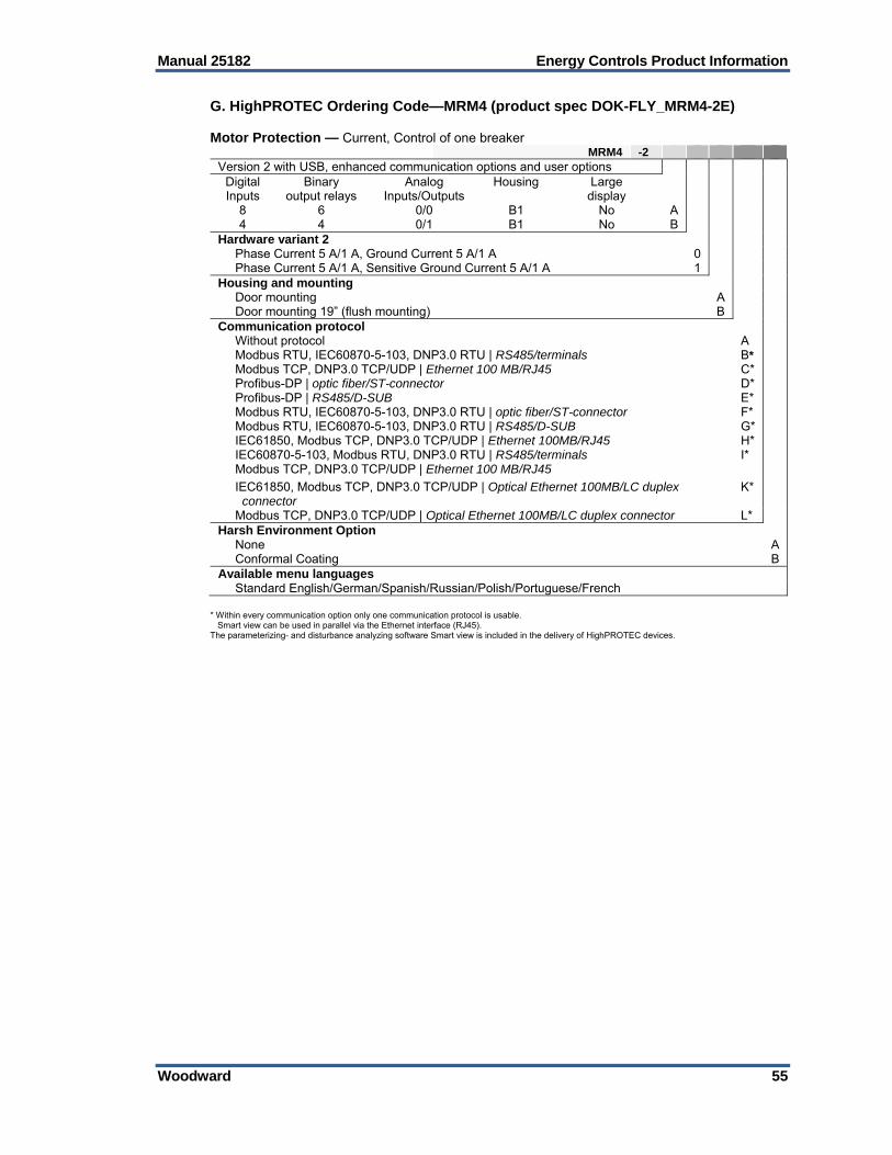
Manual 25182 Energy Controls Product Information
Woodward 55
G. HighPROTEC Ordering Code—MRM4 (product spec DOK-FLY_MRM4-2E) Motor Protection — Current, Control of one breaker
MRM4 -2 Version 2 with USB, enhanced communication options and user options
Digital Inputs
Binary output relays
Analog Inputs/Outputs
Housing Large display
8 6 0/0 B1 No A 4 4 0/1 B1 No B
Hardware variant 2 Phase Current 5 A/1 A, Ground Current 5 A/1 A 0 Phase Current 5 A/1 A, Sensitive Ground Current 5 A/1 A 1 Housing and mounting Door mounting A Door mounting 19” (flush mounting) B Communication protocol Without protocol A* Modbus RTU, IEC60870-5-103, DNP3.0 RTU | RS485/terminals B* Modbus TCP, DNP3.0 TCP/UDP | Ethernet 100 MB/RJ45 C* Profibus-DP | optic fiber/ST-connector D* Profibus-DP | RS485/D-SUB E* Modbus RTU, IEC60870-5-103, DNP3.0 RTU | optic fiber/ST-connector F* Modbus RTU, IEC60870-5-103, DNP3.0 RTU | RS485/D-SUB G* IEC61850, Modbus TCP, DNP3.0 TCP/UDP | Ethernet 100MB/RJ45 H* IEC60870-5-103, Modbus RTU, DNP3.0 RTU | RS485/terminals Modbus TCP, DNP3.0 TCP/UDP | Ethernet 100 MB/RJ45
I*
IEC61850, Modbus TCP, DNP3.0 TCP/UDP | Optical Ethernet 100MB/LC duplex connector
K*
Modbus TCP, DNP3.0 TCP/UDP | Optical Ethernet 100MB/LC duplex connector L* Harsh Environment Option None A Conformal Coating B Available menu languages Standard English/German/Spanish/Russian/Polish/Portuguese/French
* Within every communication option only one communication protocol is usable. Smart view can be used in parallel via the Ethernet interface (RJ45). The parameterizing- and disturbance analyzing software Smart view is included in the delivery of HighPROTEC devices.

Energy Controls Product Information Manual 25182
56 Woodward
H. HighPROTEC Ordering Code—MRMV4 (product spec DOK-FLY_MRMV4-2E) Motor Protection — Current, Voltage, Frequency, Power, Control of one breaker
MRMV4 -2 Version 2 with USB, enhanced communication options and user options
Digital Inputs
Binary output relays
Analog Inputs/Outputs
Housing Large display
8 7 0/4 B2 No A 8 13 0/4 B2 No C
Hardware variant 2 Phase Current 5 A/1 A, Ground Current 5 A/1 A 0 Phase Current 5 A/1 A, Sensitive Ground Current 5 A/1 A 1 Housing and mounting Door mounting A Door mounting 19” (flush mounting) B Communication protocol Without protocol * A Modbus RTU, IEC60870-5-103, DNP3.0 RTU | RS485/terminals B* Modbus TCP, DNP3.0 TCP/UDP | Ethernet 100 MB/RJ45 C* Profibus-DP | optic fiber/ST-connector D* Profibus-DP | RS485/D-SUB E* Modbus RTU, IEC60870-5-103, DNP3.0 RTU | optic fiber/ST-connector F* Modbus RTU, IEC60870-5-103, DNP3.0 RTU | RS485/D-SUB G* IEC61850, Modbus TCP, DNP3.0 TCP/UDP | Ethernet 100MB/RJ45 H* IEC60870-5-103, Modbus RTU, DNP3.0 RTU | RS485/terminals Modbus TCP, DNP3.0 TCP/UDP | Ethernet 100 MB/RJ45
I*
IEC61850, Modbus TCP, DNP3.0 TCP/UDP | Optical Ethernet 100MB/LC duplex connector
K*
Modbus TCP, DNP3.0 TCP/UDP | Optical Ethernet 100MB/LC duplex connector L* Harsh Environment Option None A Conformal Coating B Available menu languages Standard English/German/Spanish/Russian/Polish/Portuguese/French
* Within every communication option only one communication protocol is usable. Smart view can be used in parallel via the Ethernet interface (RJ45).
The parameterizing- and disturbance analyzing software Smart view is included in the delivery of HighPROTEC devices.

Manual 25182 Energy Controls Product Information
Woodward 57
I. HighPROTEC Ordering Code—MCDGV4 (product spec DOK-FLY_MCDGV4-2E) Generator Differential Protection and Grid Coupling — Current, Voltage, Frequency, Power, Control up to six breakers
MCDGV4 -2 Version 2 with USB, enhanced communication options and user options
Digital Inputs
Binary output relays
Analog Inputs/Outputs
Housing Large display
16 11 0/0 B2 Yes A 8 11 2/2 B2 Yes B
24 11 0/0 B2 Yes C 16 16 0/0 B2 Yes D
Hardware variant 2 Phase Current 5 A/1 A, Ground Current 5 A/1 A 0 Phase Current 5 A/1 A, Sensitive Ground Current 5 A/1 A 1 Housing and mounting Door mounting A Door mounting 19” (flush mounting) B Communication protocol Without protocol * A Modbus RTU, IEC60870-5-103, DNP3.0 RTU | RS485/terminals B* Modbus TCP, DNP3.0 TCP/UDP | Ethernet 100 MB/RJ45 C* Profibus-DP | optic fiber/ST-connector D* Profibus-DP | RS485/D-SUB E* Modbus RTU, IEC60870-5-103, DNP3.0 RTU | optic fiber/ST-connector F* Modbus RTU, IEC60870-5-103, DNP3.0 RTU | RS485/D-SUB G* IEC61850, Modbus TCP, DNP3.0 TCP/UDP | Ethernet 100MB/RJ45 H* IEC60870-5-103, Modbus RTU, DNP3.0 RTU | RS485/terminals
Modbus TCP, DNP3.0 TCP/UDP | Ethernet 100 MB/RJ45 I*
IEC61850, Modbus TCP, DNP3.0 TCP/UDP | Optical Ethernet 100MB/LC duplex connector
K*
Modbus TCP, DNP3.0 TCP/UDP | Optical Ethernet 100MB/LC duplex connector L* Harsh Environment Option None A Conformal Coating B Available menu languages Standard English/German/Spanish/Russian/Polish/Portuguese/French
* Within every communication option only one communication protocol is usable. Smart view can be used in parallel via the Ethernet interface (RJ45). The parameterizing- and disturbance analyzing software Smart view is included in the delivery of HighPROTEC devices.

Energy Controls Product Information Manual 25182
58 Woodward
2. HighPROTEC Services HPTCON 01 Creation of the device configuration for in-house protection according to customer data based on check lists per variation and device type. Programming of the device configuration in house is included. HPTCON 02 Creation of the device configuration for the protection, logic and single line in-house. The configuration will be effected after customer clarification according to customer data based per variation and device type. Programming of the device configuration in house is included. HPTCON 03 Programming of the device configuration per device in-house.
3. HighPROTEC Accessories Cables for PC - device communication COMPS232Nullm RS232 Zero Modem Cable with Handshake (3m) 5450-1946 Cable Standard USB-A Male to 5-POLE USB-B Mini Male 1.8M (EDS) HPTDF1 HighPROTEC distance frame HPTDF11 Frame for B1 housing 60mm depth HPTDF12 Frame for B2 housing 60mm depth URTD Universal Resistor Temperature Box URTD 01 Up to 12 sensors, PT100, Ni120, Cu10, 48-240 VAC / 48-240 VDC URTD 02 Up to 12 sensors, PT100, Ni120, Cu10, 24-48 VDC HPTURTDCON Fibre Optic Cable URDT 1M Fiber optic cable 1 m 2M Fiber optic cable 2 m 5M Fiber optic cable 5 m 10M Fiber optic cable 10 m 20M Fiber optic cable 20 m HPTTERMKIT Terminal Kits HighPROTEC for pre Wiring HPTTERMKIT 1 For devices MRI4 / MRM4 HPTTERMKIT 2 For devices MRU4 HPTTERMKIT 3 For devices MRA4D / MRMV4A / MCA4D HPTTERMKIT 4 For devices MRDT4 HPTTERMKIT 5 For devices MCDGV4 / MCDGV4B / MCDTV4B

Manual 25182 Energy Controls Product Information
Woodward 59
8—Electro-Hydraulic Governors & Actuators Part Number Non- Replaced By Preferred (CE Compliant)
1. TG Turbine Governors TG13 Screw SS, 2400 rpm 8516-038 9904-814 TG13 Screw SS, 2400 rpm B8516-038 9904-815 TG13 Screw SS, 2400 rpm C8516-038 9904-816 TG13 Screw SS, 4000 rpm F8516-039 9904-820 TG13 Screw SS, 4000 rpm G8516-039 9904-821 TG13 Screw SS, 6000 rpm J8516-040 9904-822 TG13 Screw SS, 6000 rpm H8516-040 9904-823 TG13 Lever SS, 2400 rpm B8516-041 9904-824 TG13 Lever SS, 2400 rpm C8516-041 9904-817 TG13 Lever SS, 4000 rpm C8516-042 9904-818 TG13 Lever SS, 4000 rpm D8516-042 9904-819 TG13 Lever SS, 6000 rpm B8516-043 9904-825 TG13 Lever SS, 6000 rpm C8516-043 9904-826 TG13M (motor speed setting) 8516-167 TG17 Screw SS, 2400 rpm 8516-044 9904-800 TG17 Screw SS, 2400 rpm B8516-044 9904-801 TG17 Screw SS, 2400 rpm C8516-044 9904-802 TG17 Screw SS, 4000 rpm 8516-045 9904-803 TG17 Screw SS, 4000 rpm B8516-045 9904-804 TG17 Screw SS, 4000 rpm C8516-045 9904-805 TG17 Screw SS, 6000 rpm C8516-046 9904-806 TG17 Screw SS, 6000 rpm D8516-046 9904-807 TG17 Lever SS, 2400 rpm 8516-047 9904-808 TG17 Lever SS, 2400 rpm A8516-047 9904-809 TG17 Lever SS, 4000 rpm 8516-048 9904-810 TG17 Lever SS, 4000 rpm A8516-048 9904-811 TG17 Lever SS, 6000 rpm 8516-049 9904-812 TG17 Lever SS, 6000 rpm A8516-049 9904-813 Part Number TG611 TG to TG611 Conversion Kit 8516-174 TG611-13, Screw, 2400 rpm, CCW, ATEX, w/ OTD 8516-175 TG611-13, Screw, 2400 rpm, CW, ATEX, w/ OTD 8516-176 TG611-13, Screw, 2400 rpm, CW, ATEX, w/ OTD 8516-177 TG611-13, Screw, 2400 rpm, CCW, ATEX, w/ OTD 8516-178 TG611-13, Screw, 4000 rpm, CCW, ATEX, w/ OTD 8516-179 TG611-13, Screw, 4000 rpm, CW, ATEX, w/ OTD 8516-180 TG611-13, Screw, 4000 rpm, CW, ATEX, w/ OTD 8516-181 TG611-13, Screw, 4000 rpm, CCW, ATEX, w/ OTD 8516-182 TG611-13, Screw, 6000 rpm, CCW, ATEX, w/ OTD 8516-183 TG611-13, Screw, 6000 rpm, CW, ATEX, w/ OTD 8516-184 TG611-17, Screw, 2400 rpm, CCW, ATEX, w/ OTD 8516-185 TG611-17, Screw, 2400 rpm, CW, ATEX, w/ OTD 8516-186 TG611-17, Screw, 4000 rpm, CCW, ATEX, w/ OTD 8516-187 TG611-17, Screw, 4000 rpm, CW, ATEX, w/ OTD 8516-188 TG611-17, Screw, 4000 rpm, CCW, ATEX, w/ OTD 8516-189 TG611-17, Screw, 6000 rpm, CCW, ATEX, w/ OTD 8516-190 TG611-17, Screw, 6000 rpm, CW, ATEX, w/ OTD 8516-191

Energy Controls Product Information Manual 25182
60 Woodward
2. TGE Turbine Actuators TGE13, 2400 rpm 9904-110 TGE13, 4000 rpm 9904-111 TGE13, 6000 rpm 9904-112 TGE17, 2400 rpm 9904-113 TGE17, 4000 rpm 9904-114 TGE17, 6000 rpm 9904-115

Manual 25182 Energy Controls Product Information
Woodward 61
3. VariStroke Actuators VariStroke Selection procedure:
1. Create VariStroke model number by using information from Figure 8-1 below.
2. Use the VariStroke Sizing Tool as necessary to select the correct size cylinder for the application. The VariStroke Sizing Tool is available from FTC\\servf10\saleskit\Actuation\VariStroke directory or via e-business.
3. Use the developed VariStroke model number from step #1 and the below VariStroke part number table to select the correct internal VariStroke part number. Note that the estimated delivery time for part numbers that already exist is 8-10 weeks.
4. If an internal VariStroke part number does not exist for the required model number, then contact Levi Smith or Rich Kamphaus to have a part number created. Note that the estimated delivery time for part numbers that do not yet exist in the below table is 12+ weeks.
Figure 8-1. VariStroke Model Number Information

Energy Controls Product Information Manual 25182
62 Woodward
Table 8-1. VS-I Double-Acting Integrated Models

Manual 25182 Energy Controls Product Information
Woodward 63
Table 8-2. VS-I Double-Acting Remote Servo Kit Models

Energy Controls Product Information Manual 25182
64 Woodward
Table 8-3. VS-II Double-Acting Integrated Models w/ Bottom Mount Holes

Manual 25182 Energy Controls Product Information
Woodward 65
Table 8-4. VS-II Double-Acting Integrated Models w/ Top Mount Holes

Energy Controls Product Information Manual 25182
66 Woodward
Table 8-5. VS-II Double-Acting Remote Servo Kit Models w/ Bottom Mount Holes

Manual 25182 Energy Controls Product Information
Woodward 67
Table 8-6. VS-II Double-Acting Remote Servo Kit Models w/ Top Mount Holes

Energy Controls Product Information Manual 25182
68 Woodward
Table 8-7. VS-I & II Double-Acting Servo Only Models
Table 8-8. VS-I & II Spare Parts Kits

Manual 25182 Energy Controls Product Information
Woodward 69
Part Number
4. Servo Boosters Single Cylinder 1 x 1 8901-037 Single Cylinder 2 x 1 8901-051 Tandem Cylinder 1 x 1 8901-065 Tandem Cylinder 2 x 1 8901-067 Two-stage Cylinder 2 x 1 8901-091 Two-Stage Cylinder 3 x 1 8901-103
5. CPC Current-to-Pressure Converter CPC-II - 10 bar, Div.2 (Zone2) 9907-1200 CPC-II - 10 bar, Div.1&2 (Zone1&2) 9907-1199 CPC-II - 25 bar, Div.2 (Zone2) 9907-1198 CPC-II - 25 bar, Div.1&2 (Zone1&2) 9907-1197 CPC-II - Dual Redundant, Zone 2, 0-10 bar model 9907-1253 CPC-II - Dual Redundant, Zone 2, 0-25 bar model 9907-1254 CPC-II - Voith Adapter Manifold 8928-7240 CPC-DX - Dual Redundant Skid, Zone 2, 0-10 bar model 8918-116 CPC-DX - Dual Redundant Skid, Zone 2, 0-25 bar model 8918-118 CPC-DX Repair Kits KIT-CPC REPLACEMENT, 10 BAR, ZONE 2, FOR CPC-DX SKID 8923-1996 KIT-CPC REPLACEMENT, 25 BAR, ZONE 2, FOR CPC-DX SKID 8923-1997 KIT-REPLACEMENT ISOLATION VALVE: RIGHT HAND 8923-2236 KIT-REPLACEMENT ISOLATION VALVE, LEFT HAND 8923-2242 KIT-PRESSURE GAUGE, 10BAR, FOR CPC-DX SKID 8923-2237 KIT-PRESSURE GAUGE, 25BAR, FOR CPC-DX SKID 8923-2238 KIT-SHUTTLE VALVE, FOR CPC-DX SKID 8923-2239 Part Number
6. EM Electric Actuators EML100 Actuator, 1.5” Linear, Single Feedback 9907-779 EM-300 Actuator 8256-109 Suitable EL/LQ Driver Replacement EM/LQ Driver P/Ns 8200-176, 8200-177, 8200-314, & 8200-319 can be replaced by any of these DVP P/Ns (see page 27): 8200-505, IP30, Ethernet, TB 8200-507, IP30, TB option 8200-506, IP56, Ethernet 8200-508, IP56, conduit option Note: Evaluate your application and select the suitable DVP driver that fits the environment. Please consult with a Woodward Application Engineer if there are any questions or concerns.
7. TM Actuators (Linear) TM-25LP, Standard, Extends 9907-1213 TM-25LP, Standard, Retracts 9907-1214 TM-25LP, Dual Coil, Extends w/o Feedback 9905-658 TM-25LP, Dual Coil, Retracts w/o Feedback 9905-657 TM-25LP, Dual Coil, Retracts w/ LVDT 9905-659 TM-200LP, Dual Coil, Retracts 9905-773 8. Turbine Shutdown Trip Block Assemblies QuickTrip - SIL-3, CV=10, Zone 2 Locations 2-9907-1248 QuickTrip - SIL-3, CV=10, Zone 1 Locations 1-9907-1248
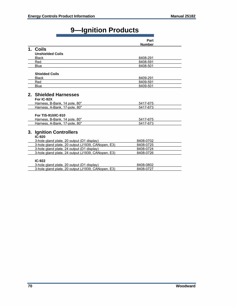
Energy Controls Product Information Manual 25182
70 Woodward
9—Ignition Products Part Number
1. Coils Unshielded Coils Black 8408-291 Red 8408-591 Blue 8408-501 Shielded Coils Black 8409-291 Red 8409-591 Blue 8409-501
2. Shielded Harnesses For IC-92X Harness, B-Bank, 14 pole, 80" 5417-675 Harness, A-Bank, 17-pole, 80" 5417-673 For TIS-910/IC-910 Harness, B-Bank, 14 pole, 80" 5417-675 Harness, A-Bank, 17-pole, 80" 5417-673
3. Ignition Controllers IC-920 3-hole gland plate, 20 output (D1 display) 8408-0702 3-hole gland plate, 20 output (J1939, CANopen, E3) 8408-0725 3-hole gland plate, 24 output (D1 display) 8408-0724 3-hole gland plate, 24 output (J1939, CANopen, E3) 8408-0726 IC-922 3-hole gland plate, 20 output (D1 display) 8408-0802 3-hole gland plate, 20 output (J1939, CANopen, E3) 8408-0727

Manual 25182 Energy Controls Product Information
Woodward 71
10—L-Series Actuators and Integrated Speed Controls
Part Number
1. L-Series Speed Control–Actuator Only L-Series Act., Type 6 Shaft, Std Cvr, Spd Ctrl w/o CAN, Dflt Pmtrs 8404-1001 L-Series Act., Type 5 Shaft, Std Cvr, Spd Ctrl w/o CAN, Dflt Pmtrs 8404-1002 L-Series Act., Type 5 Shaft, Std Cvr, Spd Ctrl w/o CAN, Coleman Pmtrs8404-1003 L-Series Act., Type 4 Shaft, Std Cvr, Spd Ctrl w/o CAN, Dflt Pmtrs 8404-1004
2. L-Series Speed Control–Actuator with ITB L-Series ITB, 25 mm, Spd Ctrl, Dflt Pmtrs 8404-2023 L-Series ITB, 30 mm, Spd Ctrl, Dflt Pmtrs 8404-2006 L-Series ITB, 36 mm, Spd Ctrl, Dflt Pmtrs 8404-2007 L-Series ITB, 43 mm, Spd Ctrl, Dflt Pmtrs 8404-2008 L-Series ITB, 50 mm, Spd Ctrl, Dflt Pmtrs 8404-2009 L-series ITB, 30 mm, Sealed, Spd Ctrl, Dflt Pmtrs 8404-2033 L-series ITB,50 mm, Sealed, Spd Ctrl, Dflt Pmtrs 8404-2052
3. L-Series Process Control with ITB (AFR is considered a form of Process Control) L-Series Trim Valve, 16 mm, Process Ctrl, Dflt Pmtrs 8404-3001 L-Series Trim Valve, 22 mm, Process Ctrl, Dflt Pmtrs 8404-3002 L-Series ITB, 25 mm Sealed, Process Ctrl, Dflt Pmtrs, N/C 8404-2061 L-Series ITB, 30 mm Sealed, Process Ctrl, Dflt Pmtrs, N/C 8404-2062 L-Series ITB, 36 mm Sealed, Process Ctrl, Dflt Pmtrs, N/C 8404-2063 L-Series ITB, 43 mm Sealed, Process Ctrl, Dflt Pmtrs, N/C 8404-2064 L-Series ITB, 50 mm Sealed, Process Ctrl, Dflt Pmtrs, N/C 8404-2065 L-Series ITB, 25 mm Sealed, AFR Ctrl, N/O 8404-2048 L-Series ITB, 30 mm Sealed, AFR Ctrl, N/O 8404-2049 L-Series ITB, 50 mm Sealed, AFR Ctrl, N/O 8404-2051
4. L-Series Speed Control–Actuator with ITB & Venturi Mixer (MAS) L-Series LC50, 25 mm ITB, 27 mm X-MIX, MAS, Spd Ctrl, Dflt Pmtrs 8404-4001 L-Series LC50, 30 mm ITB, 19 mm O-MIX, MAS, Spd Ctrl, Dflt Pmtrs 8404-4002 L-Series LC50, 36 mm ITB, 23 mm O-MIX, MAS, Spd Ctrl, Dflt Pmtrs 8404-4003 L-Series LC50, 43 mm ITB, 29 mm O-MIX, MAS, Spd Ctrl, Dflt Pmtrs 8404-4004 L-Series LC50, 50 mm ITB, 36 mm O-MIX, MAS, Spd Ctrl, Dflt Pmtrs 8404-4005 L-Series LC50, 30 mm ITB, 30 mm X-MIX, MAS, Spd Ctrl, Dflt Pmtrs 8404-4006 L-Series LC50, 36 mm ITB, 34 mm X-MIX, MAS, Spd Ctrl, Dflt Pmtrs 8404-4007 L-Series LC50, 43 mm ITB, 40 mm X-MIX, MAS, Spd Ctrl, Dflt Pmtrs 8404-4008 L-Series LC50, 50 mm ITB, 47 mm X-MIX, MAS, Spd Ctrl, Dflt Pmtrs 8404-4009 L-Series LC50, 25 mm ITB, 27 mm X-MIX, MAS, Pos Ctrl, Dflt Pmtrs 8404-4012
5. L-Series Diesel Engine Applications L-Series DER, Stanadyne Cvr/Shft, Spd Ctrl w/o CAN, Stana Pmtrs 8404-5003 L-Series DER, Delphi Cvr/Shft w/Lvr, Spd Ctrl w/o CAN, Dflt Pmtrs 8404-5004
6. L-Series Speed Control with ITB & Trim Valve L-Ser., LC50, 43 mm ITB, 29 mm O-MIX, 22 mm Trim Valve, Dflt Pmtrs8404-4019 L-Ser., LC50, 50 mm ITB, 36 mm O-MIX, 22 mm Trim Valve, Dflt Pmtrs8404-4020 L-Ser., LC50, 50 mm ITB, 47 mm X-MIX, 22 mm Trim Valve, Dflt Pmtrs8404-4021

Energy Controls Product Information Manual 25182
72 Woodward
Part Number
7. L-Series Positioner with ITB L-Series Trim Valve, 16 mm, Pos Ctrl, Dflt Pmtrs 8404-3003 L-Series Trim Valve, 22 mm, Pos Ctrl, Dflt Pmtrs 8404-3004 L-Series ITB, 25 mm Sealed, Pos Ctrl, PWM, N/C 8404-2013 L-Series ITB, 30 mm Sealed, Pos Ctrl, PWM, N/C 8404-2014 L-Series ITB, 36 mm Sealed, Pos Ctrl, PWM, N/C 8404-2015 L-Series ITB, 43 mm Sealed, Pos Ctrl, PWM, N/C 8404-2016 L-Series ITB, 50 mm Sealed, Pos Ctrl, PWM, N/C 8404-2017 L-Series ITB, 25 mm Sealed, Pos Ctrl, PWM, N/O 8404-2056 L-Series ITB, 36 mm Sealed, Pos Ctrl, PWM, N/O 8404-2057 L-Series ITB, 50 mm Sealed, Pos Ctrl, PWM, N/O 8404-2058
8. L-Series Accessories Gasket, 16 & 22 mm, 1/valve 3051-073 Gasket, 25, 30, & 36 mm ITBs 0014-00-034 Gasket, 43 & 50 mm ITBs 0108-00-021 HEGO (Heated Exhaust Gas Oxygen) Sensor 1680-6005 Kit, HEGO Mating Connector 8928-427 Cable, LCS to L-Series Adapter 5450-1033 Kit, L-Series Serial Communication Interface 8923-1061 Kit, L-Series Mating Connector 8928-396 Manifold Air Pressure Transducer 6910-314 Zero Pressure Regulator (for sizes 25, 30, or 36 mm) 0055-00-062 Zero Pressure Regulator (for sizes 43 or 50 mm) 0055-00-063
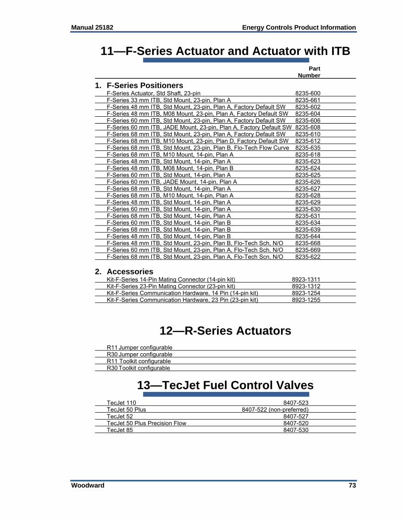
Manual 25182 Energy Controls Product Information
Woodward 73
11—F-Series Actuator and Actuator with ITB Part Number
1. F-Series Positioners F-Series Actuator, Std Shaft, 23-pin 8235-600 F-Series 33 mm ITB, Std Mount, 23-pin, Plan A 8235-661 F-Series 48 mm ITB, Std Mount, 23-pin, Plan A, Factory Default SW 8235-602 F-Series 48 mm ITB, M08 Mount, 23-pin, Plan A, Factory Default SW 8235-604 F-Series 60 mm ITB, Std Mount, 23-pin, Plan A, Factory Default SW 8235-606 F-Series 60 mm ITB, JADE Mount, 23-pin, Plan A, Factory Default SW 8235-608 F-Series 68 mm ITB, Std Mount, 23-pin, Plan A, Factory Default SW 8235-610 F-Series 68 mm ITB, M10 Mount, 23-pin, Plan D, Factory Default SW 8235-612 F-Series 68 mm ITB, Std Mount, 23-pin, Plan B, Flo-Tech Flow Curve 8235-635 F-Series 68 mm ITB, M10 Mount, 14-pin, Plan A 8235-618 F-Series 48 mm ITB, Std Mount, 14-pin, Plan A 8235-623 F-Series 48 mm ITB, M08 Mount, 14-pin, Plan B 8235-624 F-Series 60 mm ITB, Std Mount, 14-pin, Plan A 8235-625 F-Series 60 mm ITB, JADE Mount, 14-pin, Plan A 8235-626 F-Series 68 mm ITB, Std Mount, 14-pin, Plan A 8235-627 F-Series 68 mm ITB, M10 Mount, 14-pin, Plan A 8235-628 F-Series 48 mm ITB, Std Mount, 14-pin, Plan A 8235-629 F-Series 60 mm ITB, Std Mount, 14-pin, Plan A 8235-630 F-Series 68 mm ITB, Std Mount, 14-pin, Plan A 8235-631 F-Series 60 mm ITB, Std Mount, 14-pin, Plan B 8235-634 F-Series 68 mm ITB, Std Mount, 14-pin, Plan B 8235-639 F-Series 48 mm ITB, Std Mount, 14-pin, Plan B 8235-644 F-Series 48 mm ITB, Std Mount, 23-pin, Plan B, Flo-Tech Sch, N/O 8235-668 F-Series 60 mm ITB, Std Mount, 23-pin, Plan A, Flo-Tech Sch, N/O 8235-669 F-Series 68 mm ITB, Std Mount, 23-pin, Plan A, Flo-Tech Scn, N/O 8235-622
2. Accessories Kit-F-Series 14-Pin Mating Connector (14-pin kit) 8923-1311 Kit-F-Series 23-Pin Mating Connector (23-pin kit) 8923-1312 Kit-F-Series Communication Hardware, 14 Pin (14-pin kit) 8923-1254 Kit-F-Series Communication Hardware, 23 Pin (23-pin kit) 8923-1255
12—R-Series Actuators R11 Jumper configurable R30 Jumper configurable R11 Toolkit configurable R30 Toolkit configurable
13—TecJet Fuel Control Valves TecJet 110 8407-523 TecJet 50 Plus 8407-522 (non-preferred) TecJet 52 8407-527 TecJet 50 Plus Precision Flow 8407-520 TecJet 85 8407-530

Energy Controls Product Information Manual 25182
74 Woodward
14—Gas Turbine Valves Part Number
1. GS6 Gas Fuel Valve Actuator w/ On-board Driver GS6, 0.30” Port Size, Single Resolver 9908-1536 GS6, 0.45” Port Size, Single Resolver 9908-1540 GS6, 0.60” Port Size, Single Resolver 9908-1544 GS6, 0.75” Port Size, Single Resolver 9908-1552
2. GS16 Gas Fuel Valve Actuator w/ On-board Driver GS16, 1.0” Port Size, Single Resolver 9908-273 GS16, 1.5” Port Size, Single Resolver 9908-1501 GS16, 2.0” Port Size, Single Resolver 9908-1502
3. GSOV25HT Gas Fuel Shutoff Valve, 2.0” Flange GSOV25HT w/ 24 Vdc Solenoid, open pos. sw. 9907-894 GSOV25HT w/ 125 Vdc Solenoid, open pos. sw. 9907-895 GSOV25HT w/ 125 Vdc Solenoid, closed pos. sw. 9907-896 GSOV25HT w/ 24 Vdc Solenoid, open & closed pos. sw. 9907-898 GSOV25HT w/ 125 Vdc Solenoid, open & closed pos. sw. 9907-899
4. LQ6 Liquid Fuel Valve Actuator w/ On-board Driver LQ6, 0.050” Port Size, Single Resolver 9908-1519 LQ6, 0.067” Port Size, Single Resolver 9908-1520 LQ6, 0.150” Port Size, Single Resolver 9908-271
5. LQ25 Standard Valves LQ25 Valve w/ PIV, w/ SOV, w/ LmtSw, w/o Driver 0.1 in² (requires analog driver) 9908-202 0.2 in² (requires analog driver) 9907-995 0.2 in², 125 Vdc SOV/Switch, 3-speed Resolver (req. digital driver) 9907-652 0.3 in² (requires analog driver) 9907-994 0.3 in², 3-speed Resolver (requires digital driver) 9907-996
6. LSOV25 Liquid Fuel Shutoff Valve LSOV25, 24 Vdc, 0.5 NPT conduit 9907-997 LSOV25, 24 Vdc, w/ proximity switch 9904-516
7. Electric Actuator/Driver GS/LQ Analog 9907-135 EM/LQ Digital/Analog (use w/ GAP 3.0 and beyond) 8200-314 EM 24 V Digital 8200-177
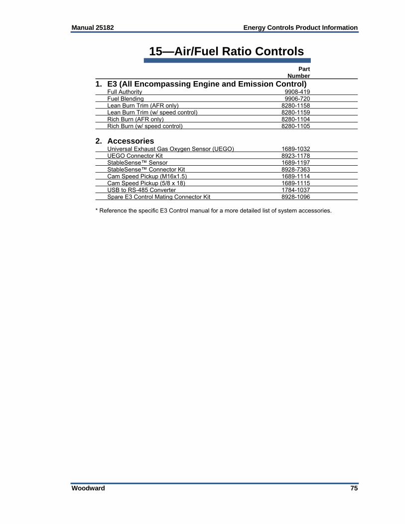
Manual 25182 Energy Controls Product Information
Woodward 75
15—Air/Fuel Ratio Controls Part Number
1. E3 (All Encompassing Engine and Emission Control) Full Authority 9908-419 Fuel Blending 9906-720 Lean Burn Trim (AFR only) 8280-1158 Lean Burn Trim (w/ speed control) 8280-1159 Rich Burn (AFR only) 8280-1104 Rich Burn (w/ speed control) 8280-1105
2. Accessories Universal Exhaust Gas Oxygen Sensor (UEGO) 1689-1032 UEGO Connector Kit 8923-1178 StableSense™ Sensor 1689-1197 StableSense™ Connector Kit 8928-7363 Cam Speed Pickup (M16x1.5) 1689-1114 Cam Speed Pickup (5/8 x 18) 1689-1115 USB to RS-485 Converter 1784-1037 Spare E3 Control Mating Connector Kit 8928-1096 * Reference the specific E3 Control manual for a more detailed list of system accessories.
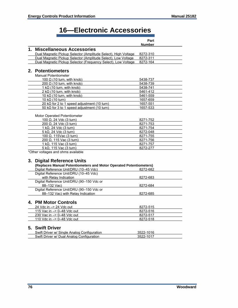
Energy Controls Product Information Manual 25182
76 Woodward
16—Electronic Accessories Part Number
1. Miscellaneous Accessories Dual Magnetic Pickup Selector (Amplitude Select), High Voltage 8272-310 Dual Magnetic Pickup Selector (Amplitude Select), Low Voltage 8272-311 Dual Magnetic Pickup Selector (Frequency Select), Low Voltage 8272-164
2. Potentiometers Manual Potentiometer 100 Ω (10 turn, with knob) 5438-737 200 Ω (10 turn, with knob) 5438-739 1 kΩ (10 turn, with knob) 5438-741 2 kΩ (10 turn, with knob) 5461-412 10 kΩ (10 turn, with knob) 5461-559 10 kΩ (10 turn) 1657-659 20 kΩ for 2 to 1 speed adjustment (10 turn) 1657-551 50 kΩ for 3 to 1 speed adjustment (10 turn) 1657-533 Motor Operated Potentiometer 100 Ω, 24 Vdc (3 turn) 8271-752 200 Ω, 24 Vdc (3 turn) 8271-753 1 kΩ, 24 Vdc (3 turn) 8271-754 5 kΩ, 24 Vdc (3 turn) 8272-048 100 Ω, 115Vac (3 turn) 8271-755 200 Ω, 115 Vac (3 turn) 8271-756 1 kΩ, 115 Vac (3 turn) 8271-757 5 kΩ, 115 Vac (3 turn) 8272-277 *Other voltages and ohms available
3. Digital Reference Units (Replaces Manual Potentiometers and Motor Operated Potentiometers) Digital Reference Unit/DRU (10–45 Vdc) 8272-682 Digital Reference Unit/DRU (10–45 Vdc) with Relay Indication 8272-683 Digital Reference Unit/DRU (90–150 Vdc or 88–132 Vac) 8272-684 Digital Reference Unit/DRU (90–150 Vdc or 88–132 Vac) with Relay Indication 8272-685
4. PM Motor Controls 24 Vdc in –> 24 Vdc out 8272-515 115 Vac in –> 0–48 Vdc out 8272-516 230 Vac in –> 0–48 Vdc out 8272-517 110 Vdc in –> 0–48 Vdc out 8272-518
5. Swift Driver Swift Driver w/ Single Analog Configuration 3522-1016 Swift Driver w/ Dual Analog Configuration 3522-1017

Manual 25182 Energy Controls Product Information
Woodward 77
17—Mechanical-Hydraulic Controls SG A low-cost, simple, mechanical droop governor for smaller high-speed diesel, gas, and
gasoline engines. PSG A pressure-compensated, mechanical governor with the stability necessary for droop or
isochronous control of small diesel, gas, or gasoline engines. UG A rugged, dependable governor commonly used on medium to large diesel, gas,
gasoline, and dual-fuel engines, the UG features isochronous or droop control, dashpot compensation, and a self contained oil sump.
18—Woodward Authorized Facilities The Woodward website has a searchable directory of all Woodward plants, offices, distributors, and other authorized facilities (www.woodward.com/directory.aspx).
19—Repair and Remanufacturing Services Woodward offers repair and remanufacturing to customers that are authorized to purchase direct. The spreadsheet below contains pricing for those authorized customers and is not intended to represent the pricing for our OEM, Channel Partners, Distributors, or Authorized Service facilities. The Flat Rate pricing program was designed to simply and rapidly process units for our authorized customer base. Pricing is reviewed quarterly and subject to change without notice. All items returned for Repair or Reman options must be in repairable condition. Non-repairable and cannibalized items will be subject to replacement at list price less
applicable discounts. Pricing does not include conversions from one part number to another, which will be charged
as time and material. Pricing does not include repair or warranty evaluation of any pre-production item numbers
[E/C = numeric]. All applicable charges for expedite, testing, and engineering will apply per Miscellaneous
Charges 5-09-1208. Repaired units [mechanical & electrical] carry the ICG standard repair warranty of 180 days. Remanufactured and exchange units carry the standard ICG new product warranty of 18
months. Once work has commenced, pricing cannot be switched from flat rate to time and material
repair or reman. Time and Material repairs will be calculated by price of parts and applicable labor rates. Woodward also offers a Replacement Exchange program to our customers that are authorized to purchase direct. Original invoice or billing will include a core charge in the pricing. 30 days from shipment of exchange unit, customer must return core for credit. Cores returned after 30 days will not be issued core credit If core is non-repairable or cannibalized, a core credit will NOT be issued. Replacement exchange program is contingent on availability of units. Program is designed to support emergency situations where the customer requires an
immediate field replacement.

We appreciate your comments about the content of our publications.
Send comments to: [email protected]
Please reference publication 25182R.
ËB25182:R´¹·¸´¹Î
PO Box 1519, Fort Collins CO 80522-1519, USA 1000 East Drake Road, Fort Collins CO 80525, USA Phone +1 (970) 482-5811 Fax +1 (970) 498-3058
Email and Website—www.woodward.com
Woodward has company-owned plants, subsidiaries, and branches, as well as authorized distributors and other authorized service and sales facilities throughout the world.
Complete address / phone / fax / email information for all locations is available on our website.


![36637_E[1] WOODward](https://static.fdocuments.in/doc/165x107/5571fba04979599169956701/36637e1-woodward.jpg)