PT-DZ570 Spec File - Panasonic Businessbusiness.panasonic.de/.../PT-DZ570_specifications_EN.pdf ·...
14
S P E C F I L E Product Number : PT- DZ570 Product Name : DLP ™ Projector As of October 2010. Specifications subject to change without notice. SFD10M012 1/14
Transcript of PT-DZ570 Spec File - Panasonic Businessbusiness.panasonic.de/.../PT-DZ570_specifications_EN.pdf ·...

S P E C F I L E
Product Number : PT-DZ570Product Name : DLP ™ Projector
As of October 2010. Specifications subject to change without notice.
SFD10M012
1 / 1 4

S P E C F I L E
PT-DZ570DLP™ Projector
As of October 2010
SFD10M012
2 / 1 4
Specifications
Main unitPower supplyPower consumption
DLP™ chip Panel sizeDisplay methodPixels
LensThrow ratio 16:10 aspect ratio
16:9 aspect ratioLampScreen sizeBrightness* 2
Center-to-corner uniformity* 2
Contrast* 2
ResolutionScanning frequency HDMI/DVI-D
RGBYPBPR (YCBCR)
Video/S-Video
Optical axis shiftKeystone correction rangeInstallationTerminals HDMI IN
DVI-D IN
RGB 1 INR, G, B
Y, PB, PR
100–240 V AC, 5.0–1.9 A, 50/60 Hz415 W (500 VA) (0.3 W at 100 –120 V AC, 0.4 W at 220–240 V AC with standby modeset to ECO*1, 15 W with standby mode set to NORMAL. Both with fanstopped.)17.0 mm (0.67 inches) diagonal (16:10 aspect ratio)DLP™ chip × 1, DLP™ system2,304,000 (1,920 × 1,200) × 1, total of 2,304,000 pixelsManual zoom (2× zoom), manual focus F 2.0–3.4, f 21.5–43.0 mm1.45–2.94:11.46 – 2.94:1300 W (max. 310 W) UHM lamp1.02–7.62 m (40– 300 inches), 16:10 aspect ratio 4,000 lumens (lamp mode: NORMAL)90%2,000:1 (full on/full off)1,920 × 1,2 00 pixelsfH: 27 kHz –100 kHz, fV: 24 Hz–120 Hz, dot clock: 25 MHz–162 MHzfH: 15 kHz–100 kHz, fV: 24 Hz–120 Hz, dot clock: 162 MHz or lower480i (525i): fH 15.75 kHz; fV 60 Hz, 576i (625i): fH 15.63 kHz; fV 50 Hz,480p (525p): fH 31.50 kHz; fV 60 Hz, 576p (625p): fH 31.25 kHz; fV 50 Hz,720 (750)/60p: fH 45.00 kHz; fV 60 Hz, 720 (750)/50p: fH 37.50 kHz; fV 50 Hz,1035/60i: fH 33.75 kHz; fV 60 Hz, 1080 (1125)/60i: fH 33.75 kHz; fV 60 Hz,1080 (1125)/50i: fH 28.13 kHz; fV 50 Hz, 1080/25p: fH 28.13 kHz; fV 25 Hz, 1080/24p: fH 27.00 kHz; fV 24 Hz,1080/24sF: fH 27.00 kHz; fV 48 Hz,1080/30p: fH 33.75 kHz; fV 30 Hz,1080/60p: fH 67.50 kHz; fV 60 Hz, 1080/50p: fH 56.25 kHz; fV 50 HzfH: 15.75 kHz, fV: 60 Hz [NTSC/NTSC4.43/PAL-M/PAL60]fH: 15.63 kHz, fV: 50 Hz [PAL/PAL-N/SECAM]Vertical: +60% (manual), horizontal: ±10% (manual)Vertical: ±40°Ceiling/floor, front/rearHDMI 19-pin × 1
Deep Color, HDCP compatible480p, 576p, 720/60p, 720/50p, 1080/60i, 1080/50i, 1080/24p,1080/24sF, 1080/25p, 1080/30p, 1080/60p, 1080/50p VGA (640 × 480) –WUXGA*3 (1,920 × 1,200), compatible with non-interlaced signals only, dot clock: 25 MHz–162 MHzAudio signal: linear PCM (sampling frequencies: 48 kHz, 44.1 kHz,32 kHz)
DVI-D 24-pin × 1DVI 1.0 compliant, HDCP compatible, for single link only480p, 576p, 720/60p, 720/50p, 1080/60i, 1080/50i, 1080/24p,1080/24sF, 1080/25p, 1080/30p, 1080/60p, 1080/50p VGA (640 × 480) –WUXGA*3 (1,920 × 1,200), compatible with non-interlaced signals only, dot clock: 25 MHz–162 MHz
BNC × 5R: 0.7 Vp-p, 75 ohms, G: 0.7 Vp-p (G: 1.0 Vp-p for sync on G), 75 ohms,B: 0.7 Vp-p, 75 ohmsHD/VD, SYNC: High impedance, TTL (positive/negative)NOTE: SYNC/HD and VD terminals do not accept tri-level sync signals.
Y: 1.0 Vp-p (including sync signal), PB/PR: 0.7 Vp-p, 75 ohms

S P E C F I L E
PT-DZ570DLP™ Projector
As of October 2010
SFD10M012
3 / 1 4
RGB 2 INR, G, B
Y, PB, PRVIDEO INS-VIDEO INAUDIO IN 1AUDIO IN 2AUDIO IN 3AUDIO OUTSERIAL INREMOTE INLAN
WIRELESS MODULEPower cord lengthCabinet materials Dimensions (W × H × D)
WeightOperating temperatureOperating humidity
Remote control unitPower supplyOperation range *6
Dimensions (W × H × D)Weight
Supplied accessories
Optional accessoriesReplacement lamp unit
Ceiling mount bracket
Wireless module
D-sub HD 15-pin × 1R: 0.7 Vp-p, 75 ohms, G: 0.7 Vp-p (G: 1.0 Vp-p for sync on G), 75 ohms,B: 0.7 Vp-p, 75 ohmsHD/VD, SYNC: High impedance, TTL (positive/negative)NOTE: SYNC/HD and VD terminals do not accept tri-level sync signals.
Y: 1.0 Vp-p (including sync signal), PB/PR: 0.7 Vp-p, 75 ohmsBNC × 1, 1.0 Vp-p, 75 ohmsMini DIN 4-pin × 1, Y: 1.0 Vp-p, C: 0.286 Vp-p, 75 ohmsRCA × 2 (L, R × 1), 0.5 VrmsM3 × 1 (L, R × 1), 0.5 VrmsM3 × 1 (L, R × 1), 0.5 VrmsM3 × 1 (L, R × 1) (monitor out: 0– 2.0 Vrms, variable)D-sub 9-pin × 1 for external control (RS-232C compliant)D-sub 9-pin × 1 for external control (parallel)RJ-45 × 1 for network connection, 100Base-TX/10Base-T, compliantwith PJLink™Connector for optional wireless module ET-WM200U/WM200E × 13.0 m (9 ft 10 in)Molded plastic (PC + ABS)332 mm × 168 mm*4 × 484.5 mm*5
(13-1/16˝ × 6-5/8˝ *4 × 19-1/16˝ *5)Approx. 8.5 kg (18.7 lbs)0°–45°C (32°–113°F)20%–80% (no condensation)
3 V DC (R6/LR6/AA type battery × 2)Approx. 15 m (49 ft 3 in) when operated from directly in front of thesignal receptor48 × 163 × 24.5 mm (1-7/8˝ × 6-13/32˝ × 31/32˝)Approx. 117 g (4.1 oz) (including batteries)
Power cord with security lock (× 1)Wireless remote control unit (× 1)Batteries for remote control (R6/LR6/AA type × 2)Wire rope (× 1)Software CD-ROM (Logo Transfer Software, Multi Projector Monitoring
and Control Software Ver. 2, Wireless Manager ME 5.5) (× 1)
ET-LAD60AET-LAD60AW (Twin Pack)ET-PKD110H (for high ceilings)ET-PKD110S (for low ceilings)ET-WM200U (for North America)ET-WM200E (for Europe and Asia)
Weights and dimensions shown are approximate. Specifications subject to change without notice.*1 When the standby mode is set to ECO, network functions such as power on over the LAN network will not operate. Also, only certain com-
mands can be received for external control using the serial terminal.*2 Measurement, measuring conditions, and method of notation all comply with ISO 21118 international standards.*3 Compliant with VESA CVT-RB.*4 With legs at shortest position.*5 Including the lens.*6 Operation range differs depending on environments.*7 The operation system must be pre-installed at the factory or clean installed.

48
4.5
(1
9-1
/16
)
42
5 (
16
-23
/32
)5
9.5
(2-1
1/3
2)
9 (
11
/32
)
7 (
9/3
2)
332 (13-1/16)
90(3-17/32)
16
5 (
6-1
/2)
16
8 (
6-5
/8)
Dimensions
unit : mm (inch)NOTE: This illustration is not drawn to scale.
S P E C F I L E
PT-DZ570DLP™ Projector
As of October 2010
SFD10M012
4 / 1 4
Terminals
1 2 3 4 5
8 9 1110
12 13
6 7 1 LAN connector
2 HDMI input
3 Video input
4 S-Video input
5 RGB 1 input
6 RGB 2 Input
7 DVI-D input
8 Audio 1 input
9 Audio 2 input
10 Audio 3 input
11 Audio out put
12 Remote input
13 Serial input

S P E C F I L E
PT-DZ570DLP™ Projector
As of October 2010
SFD10M012
5 / 1 4
Standard setting-up position
Upper edge of projected image
230
(9-1/16 ˝ )
253.5
(9-31/32˝ )
∅ 60.5(2-3/8 ˝ )
*
Lower edge of projected image
Projected image
L
L
L3
40
–4
20
(13
-3/8
˝–16
-17
/32
˝)
43
1–
511
(16
-31
/32
˝–2
0-1
/8˝)
100
(3-1
5/1
6˝)
34
4(1
3-1
7/3
2˝)
100(3-15/16 ˝ )
300(11-13/16˝ )
Projected image
HH
ET-PKD110H
ET-PKD110H
unit : mm (inch)
* Adjustable in 40 mm (1-9/16˝) steps.
C au t i o n :• All construction work should be done by a qualified technician.• When mounting to the ceiling, use the special mounting bracket. To prevent the projector from swaying or drop-
ping, attach the wire that is included with the projector between the mounting bracket and the ceiling.
1.02 m
1.27 m
1.52 m
1.78 m
2.03 m
2.29 m
2.54 m
3.05 m
3.81 m
5.08 m
6.35 m
7.62 m
1.23
1.55
1.87
2.19
2.51
2.83
3.15
3.79
4.75
6.35
7.95
9.55
2.51
3.15
3.79
4.43
5.07
5.70
6.34
7.62
9.53
12.73
15.92
19.11
-0.05
-0.07
-0.08
-0.09
-0.11
-0.12
-0.14
-0.16
-0.20
-0.27
-0.34
-0.40
0.27
0.34
0.40
0.47
0.54
0.61
0.67
0.81
1.01
1.35
1.68
2.02
–
–
–
–
–
–
–
–
–
–
–
–
40˝
50˝
60˝
70˝
80˝
90˝
100˝
120˝
150˝
200˝
250˝
300˝
/
/
/
/
/
/
/
/
/
/
/
/
(4.1)
(5.1)
(6.2)
(7.2)
(8.3)
(9.3)
(10.4)
(12.5)
(15.6)
(20.9)
(26.1)
(31.4)
(8.2)
(10.3)
(12.4)
(14.5)
(16.6)
(18.7)
(20.8)
(24.9)
(31.2)
(41.7)
(52.2)
(62.6)
(-0.2
(-0.2
(-0.3
(-0.3
(-0.4
(-0.4
(-0.4
(-0.5
(-0.7
(-0.9
(-1.1
(-1.3
0.9)
1.1)
1.3)
1.5)
1.8)
2.0)
2.2)
2.7)
3.3)
4.4)
5.5)
6.6)
–
–
–
–
–
–
–
–
–
–
–
–
Projection size
[diagonal]
Projection distance [L]
Min [wide] Max [telephoto]
Height from the edge of screento center of lens [H ]
Projection distance for 16:10 aspect ratio screenunit: meters (feet)
NOTE:
• The value for L (distance to screen) varies slightly within ±5% depending on the zoom lens characteristics.
• At the shortest projection distance, the zoom lens characteristics may cause slight image distortion.
• When vertical keystone correction is used, the image is corrected in the direction that reduces its projected size.
• The brightness varies depending on the zoom setting.
NOTE:
Illustrations show the projector installedusing optional ceiling bracket.
This illustration is not drawn to scale.

S P E C F I L E
PT-DZ570DLP™ Projector
As of October 2010
SFD10M012
6 / 1 4
NOTE:
• The value for L (distance to screen) varies slightly within ±5% depending on the zoom lens characteristics.
• At the shortest projection distance, the zoom lens characteristics may cause slight image distortion.
• When vertical keystone correction is used, the image is corrected in the direction that reduces its projected size.
• The brightness varies depending on the zoom setting.
Calculation of the projection distance
For a screen size different from the above, use the equation below to calculate the projection distance.
Aspect ratio 16:10minimum L (m) = (diagonal screen size in inches) × 0.0320 – 0.0546maximum L (m) = (diagonal screen size in inches) × 0.0638 – 0.0408
Aspect ratio 16:9minimum L (m) = (diagonal screen size in inches) × 0.0329 – 0.0546maximum L (m) = (diagonal screen size in inches) × 0.0656 – 0.0408
NOTE: Distances calculated with the above equations will include a slight error.
1.02 m
1.27 m
1.52 m
1.78 m
2.03 m
2.29 m
2.54 m
3.05 m
3.81 m
5.08 m
6.35 m
7.62 m
1.26
1.59
1.92
2.25
2.58
2.91
3.24
3.90
4.88
6.53
8.17
9.82
2.58
3.24
3.89
4.55
5.21
5.86
6.52
7.83
9.80
13.08
16.36
19.64
-0.08
-0.10
-0.13
-0.15
-0.17
-0.19
-0.21
-0.25
-0.31
-0.42
-0.52
-0.62
0.25
0.31
0.37
0.44
0.50
0.56
0.62
0.75
0.93
1.25
1.56
1.87
–
–
–
–
–
–
–
–
–
–
–
–
(4.2)
(5.3)
(6.3)
(7.4)
(8.5)
(9.6)
(10.7)
(12.8)
(16.1)
(21.5)
(26.9)
(32.3)
(8.4)
(10.6)
(12.7)
(14.9)
(17.0)
(19.2)
(21.3)
(25.6)
(32.1)
(42.9)
(53.6)
(64.4)
40˝
50˝
60˝
70˝
80˝
90˝
100˝
120˝
150˝
200˝
250˝
300˝
/
/
/
/
/
/
/
/
/
/
/
/
(-0.3
(-0.3
(-0.4
(-0.5
(-0.5
(-0.6
(-0.7
(-0.8
(-1.0
(-1.4
(-1.7
(-2.0
0.8)
1.0)
1.2)
1.4)
1.6)
1.8)
2.0)
2.5)
3.1)
4.1)
5.1)
6.1)
–
–
–
–
–
–
–
–
–
–
–
–
Projection size
[diagonal]
Projection distance [L]
Min [wide] Max [telephoto]
Height from the edge of screento center of lens [H ]
Projection distance for 16:9 aspect ratio screenunit: meters (feet)
S P E C F I L E
PT-DZ570DLP™ Projector
As of October 2010
SFD10M012
7 / 1 4
H(Width of
projected image)
V(H
eig
ht
of
pro
jec
ted
im
ag
e) 0.4
6V
0.6
V
0.1H0.1H
Standard postition of projected image H
(Width ofprojected image)
V(H
eig
ht
of
pro
jec
ted
im
ag
e)
0.4
6V
0.6
V
0.1H0.1H
Standard postition of projected image
36
0°
-15°
+15
°
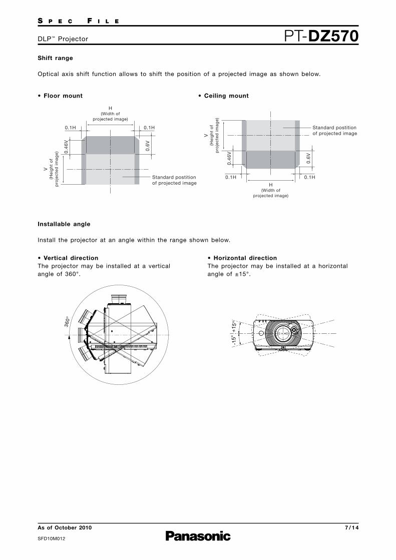
Shift range
Optical axis shift function allows to shift the position of a projected image as shown below.
Installable angle
Install the projector at an angle within the range shown below.
• Vertical directionThe projector may be installed at a verticalangle of 360°.
• Horizontal directionThe projector may be installed at a horizontalangle of ±15°.
• Floor mount • Ceiling mount
S P E C F I L E
PT-DZ570DLP™ Projector
As of October 2010
SFD10M012
8 / 1 4
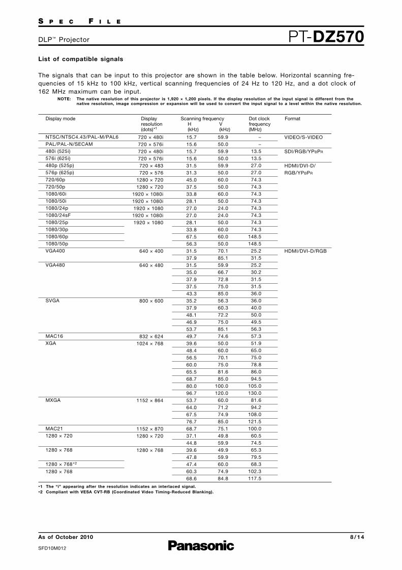
List of compatible signals
The signals that can be input to this projector are shown in the table below. Horizontal scanning fre-quencies of 15 kHz to 100 kHz, vertical scanning frequencies of 24 Hz to 120 Hz, and a dot clock of162 MHz maximum can be input.
NOTE: The native resolution of this projector is 1,920 × 1,200 pixels. If the display resolution of the input signal is different from thenative resolution, image compression or expansion will be used to convert the input signal to a level within the native resolution.
Display mode Displayresolution(dots)*1
Scanning frequencyH(kHz)
V(kHz)
Dot clockfrequency(MHz)
Format
720 × 480i
720 × 576i
720 × 480i
720 × 576i
720 × 483
720 × 576
1280 × 720
1280 × 720
1920 × 1080i
1920 × 1080i
1920 × 1080
1920 × 1080i
1920 × 1080
640 × 400
640 × 480
800 × 600
832 × 624
1024 × 768
1152 × 864
1152 × 870
1280 × 720
1280 × 768
15.7
15.6
15.7
15.6
31.5
31.3
45.0
37.5
33.8
28.1
27.0
27.0
28.1
33.8
67.5
56.3
31.5
37.9
31.5
35.0
37.9
37.5
43.3
35.2
37.9
48.1
46.9
53.7
49.7
39.6
48.4
56.5
60.0
65.5
68.7
80.0
96.7
53.7
64.0
67.5
76.7
68.7
37.1
44.8
39.6
47.8
47.4
60.3
68.6
59.9
50.0
59.9
50.0
59.9
50.0
60.0
50.0
60.0
50.0
24.0
24.0
50.0
60.0
60.0
50.0
70.1
85.1
59.9
66.7
72.8
75.0
85.0
56.3
60.3
72.2
75.0
85.1
74.6
50.0
60.0
70.1
75.0
81.6
85.0
100.0
120.0
60.0
71.2
74.9
85.0
75.1
49.8
59.9
49.9
59.9
60.0
74.9
84.8
−
−
13.5
13.5
27.0
27.0
74.3
74.3
74.3
74.3
74.3
74.3
74.3
74.3
148.5
148.5
25.2
31.5
25.2
30.2
31.5
31.5
36.0
36.0
40.0
50.0
49.5
56.3
57.3
51.9
65.0
75.0
78.8
86.0
94.5
105.0
130.0
81.6
94.2
108.0
121.5
100.0
60.5
74.5
65.3
79.5
68.3
102.3
117.5
NTSC/NTSC4.43/PAL-M/PAL6
PAL/PAL-N/SECAM
480i (525i)
576i (625i)
480p (525p)
576p (625p)
720/60p
720/50p
1080/60i
1080/50i
1080/24p
1080/24sF
1080/25p
1080/30p
1080/60p
1080/50p
VGA400
VGA480
SVGA
MAC16
XGA
MXGA
MAC21
1280 × 720
1280 × 768
1280 × 768*2
1280 × 768
VIDEO/S-VIDEO
SDI/RGB/YPBPR
HDMI/DVI-D/
RGB/YPBPR
HDMI/DVI-D/RGB
*1 The “i” appearing after the resolution indicates an interlaced signal.
*2 Compliant with VESA CVT-RB (Coordinated Video Timing-Reduced Blanking).

S P E C F I L E
PT-DZ570DLP™ Projector
As of October 2010
SFD10M012
9 / 1 4
Display mode Displayresolution(dots)*1
Scanning frequencyH(kHz)
V(kHz)
Dot clockfrequency(MHz)
Format
1280 x 800
1280 x 960
1280 × 1024
1280 × 768
1400 × 1050
1440 × 900
1600 × 1200
1680 × 1050
1920 × 1080
1920 × 1200
41.3
49.7
49.3
62.8
71.6
60.0
52.4
64.0
72.3
78.2
80.0
91.1
47.7
39.6
54.1
64.0
65.2
65.3
78.8
82.2
55.9
46.3
75.0
65.3
54.1
55.6
66.6
67.2
61.8
74.0
74.6
50.0
59.8
59.9
74.9
84.9
60.0
50.0
60.0
66.3
72.0
75.0
85.0
59.8
49.9
50.0
60.0
60.0
60.0
72.0
75.0
59.9
49.9
60.0
60.0
50.0
49.9
59.9
60.0
49.9
60.0
59.9
68.0
83.5
71.0
106.5
122.5
108.0
88.0
108.0
125.0
135.1
135.0
157.5
84.8
69.0
99.9
108.0
122.6
121.8
149.3
155.9
106.5
86.8
162.0
146.3
119.5
141.5
138.5
173.0
158.3
154.0
193.3
1280 × 800
1280 × 800*2
1280 × 800
MSXGA
SXGA
1366×768
SXGA+
WXGA+
UXGA60
WSXGA+
1920×1080
1920×1080*2
1920×1080
WUXGA
WUXGA*2
WUXGA
HDMI/DVI-D/RGB
RGB
HDMI/DVI-D/RGB
RGB
*1 The “i” appearing after the resolution indicates an interlaced signal.
*2 Compliant with VESA CVT-RB (Coordinated Video Timing-Reduced Blanking
S P E C F I L E
PT-DZ570DLP™ Projector
As of October 2010
SFD10M012
10 / 1 4
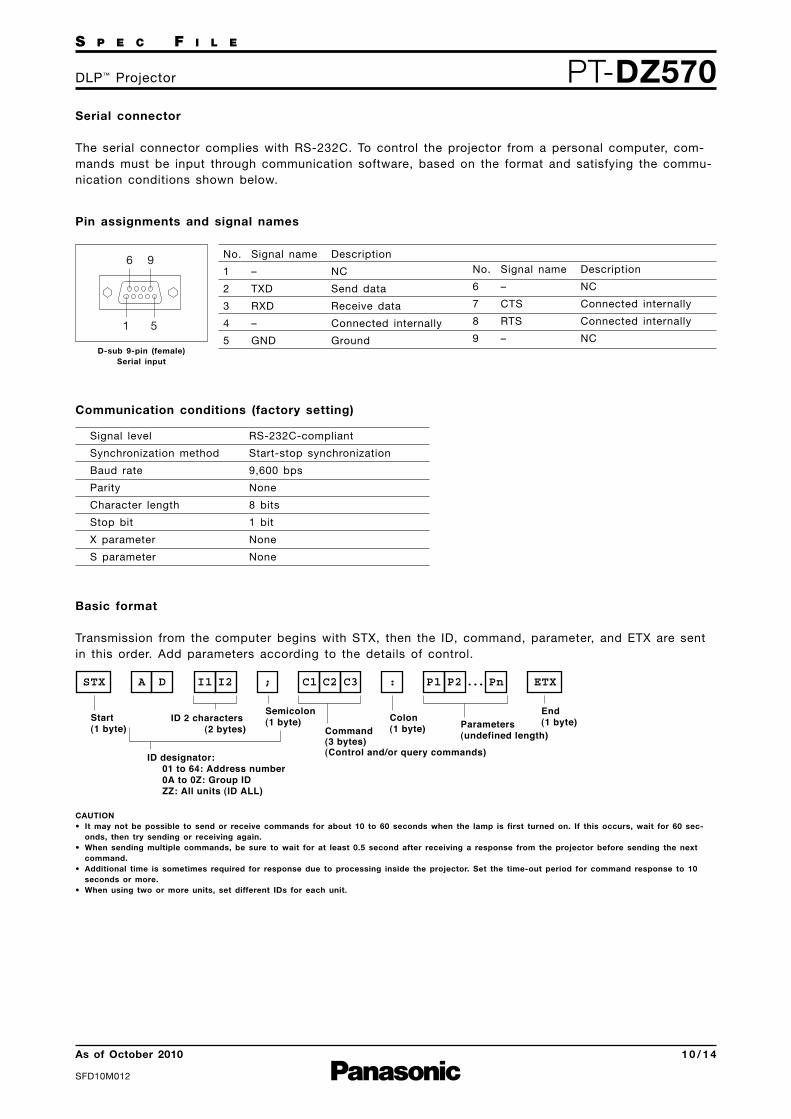
Serial connector
The serial connector complies with RS-232C. To control the projector from a personal computer, com-mands must be input through communication software, based on the format and satisfying the commu-nication conditions shown below.
Basic format
Transmission from the computer begins with STX, then the ID, command, parameter, and ETX are sentin this order. Add parameters according to the details of control.
Communication conditions (factory setting)
Pin assignments and signal names
6
1 5
9
D-sub 9-pin (female)Serial input
Description
NC
Send data
Receive data
Connected internally
Ground
Signal name
–
TXD
RXD
–
GND
No.
1
2
3
4
5
Description
NC
Connected internally
Connected internally
NC
Signal name
–
CTS
RTS
–
No.
6
7
8
9
CAUTION• It may not be possible to send or receive commands for about 10 to 60 seconds when the lamp is first turned on. If this occurs, wait for 60 sec-onds, then try sending or receiving again.
• When sending multiple commands, be sure to wait for at least 0.5 second after receiving a response from the projector before sending the nextcommand.
• Additional time is sometimes required for response due to processing inside the projector. Set the time-out period for command response to 10seconds or more.
• When using two or more units, set different IDs for each unit.
Start(1 byte)
End(1 byte)Colon
(1 byte)Semicolon(1 byte)
ID designator:01 to 64: Address number0A to 0Z: Group IDZZ: All units (ID ALL)
ID 2 characters (2 bytes) Parameters
(undefined length)Command(3 bytes)(Control and/or query commands)
STX ETXC1 P1 P2 ... PnC2A D I1 I2 C3 : ;
Signal level
Synchronization method
Baud rate
Parity
Character length
Stop bit
X parameter
S parameter
RS-232C-compliant
Start-stop synchronization
9,600 bps
None
8 bits
1 bit
None
None
S P E C F I L E
PT-DZ570DLP™ Projector
As of October 2010
SFD10M012
11 / 1 4
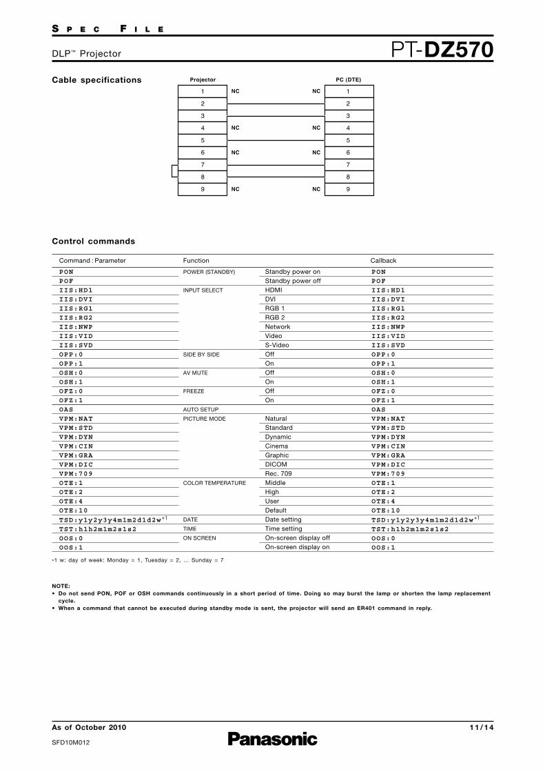
Control commands
Command : Parameter Function Callback
PONPOFIIS:HD1IIS:DVIIIS:RG1IIS:RG2IIS:NWPIIS:VIDIIS:SVDOPP:0OPP:1OSH:0OSH:1OFZ:0OFZ:1OASVPM:NATVPM:STDVPM:DYNVPM:CINVPM:GRAVPM:DICVPM:709OTE:1OTE:2OTE:4OTE:10
TSD:y1y2y3y4m1m2d1d2w *1
TST:h1h2m1m2s1s2OOS:0OOS:1
Standby power onStandby power offHDMIDVIRGB 1RGB 2NetworkVideoS-VideoOffOnOffOnOffOn
NaturalStandardDynamicCinemaGraphicDICOMRec. 709MiddleHighUserDefaultDate settingTime settingOn-screen display offOn-screen display on
POWER (STANDBY)
INPUT SELECT
SIDE BY SIDE
AV MUTE
FREEZE
AUTO SETUP
PICTURE MODE
COLOR TEMPERATURE
DATE
TIME
ON SCREEN
PONPOFIIS:HD1IIS:DVIIIS:RG1IIS:RG2IIS:NWPIIS:VIDIIS:SVDOPP:0OPP:1OSH:0OSH:1OFZ:0OFZ:1OASVPM:NATVPM:STDVPM:DYNVPM:CINVPM:GRAVPM:DICVPM:709OTE:1OTE:2OTE:4OTE:10
TSD:y1y2y3y4m1m2d1d2w *1
TST:h1h2m1m2s1s2OOS:0OOS:1
Cable specifications123456789
123456789
PC (DTE)ProjectorNC
NC
NC
NC
NC
NC
NC
NC
*1 w: day of week: Monday = 1, Tuesday = 2, ... Sunday = 7
NOTE:• Do not send PON, POF or OSH commands continuously in a short period of time. Doing so may burst the lamp or shorten the lamp replacementcycle.
• When a command that cannot be executed during standby mode is sent, the projector will send an ER401 command in reply.

S P E C F I L E
PT-DZ570DLP™ Projector
As of October 2010
SFD10M012
12 / 1 4
Status request commands
Command : Parameter Function DescriptionCallbackQPW
QIN
OPP
QSH
QFZ
QOS
QST
Q$L
QLP
QPM
QTM:0
QTM:1
QTM:2
QGD
QGT
Main power status
Input signal status
Side-by-side function status
AV mute function status
Freeze function status
On-screen display status
Projector run timeLamp run timeLamp power mode status
Picture mode status
Temperature status
Date setting statusTime setting status
Standby (Off)OnHDMIDVIRGB 1RGB 2NetworkVideoS-VideoOffOnOffOnOffOnOffOn00000h–99999h0000h–9999hNormalEcoNaturalStandarddynamicCinemaGraphicDICOMRec. 709p0 = Intake airp1 = Around lampp2 = Optics moduleyyyymmddw*2 hhmmss
000
001
HD1
DVI
RG1
RG2
NWP
VID
SVD
0
1
0
1
0
1
0
1
p1p2p3p4p5
p1p2p3p4
0
1
NAT
STD
DYN
CIN
GRA
DIC
709
p1p2p3p4/p5p6p7p8 *1
y1y2y3y4m1m2d1d2w
h1h2m1m2s1s2
Command example
To set the on-screen display off, send the command as shown below.
ADZZ OOS : 30; ETX
ID Address Command
STX
Start Parameter End
NOTE: When sending commands without parameters, a colon (:) is not necessary.
*1 p1p2p3p4: Celsius (°C), p5p6p7p8: Fahrenheit (°F)
*2 w: day of week: Monday = 1, Tuesday = 2, ... Sunday = 7
NOTE: If a wrong command is received, the projector will send an ER401 or ER402 command to the computer.

S P E C F I L E
PT-DZ570DLP™ Projector
As of October 2010
SFD10M012
13 / 1 4
Notes on projector placement and operation
The projector uses a high-wattage lamp that becomes very hot during operation. Please observe thefollowing precautions.
1. Never place objects on top of the projector while it is operating.
2. Make sure there is an unobstructed space of 500 mm (19-11/16˝) or more around the projector’sexhaust openings.
3. Do not stack projector units directly on top of one another. If two units must be stacked for back-up use in ordinary projection, use a method as shown below and provide ample space between theunits to ensure that exhaust heat does not accumulate near the intake opening or around the units.Dual stacked projection is not recommended.
4. Make sure that nothing blocks the projector’s air intake and exhaust openings. Also, install the pro-jector so that cool or hot air from other air conditioning equipment does not flow directly towardthe projector’s air intake or exhaust openings.
5. Do not install the projector in an enclosed space. If it is necessary to install it in an enclosedspace, add a separate ventilation system. If ventilation is insufficient, hot air will accumulate at theintake opening. This may cause the projector’s protective circuit to interrupt projector operation.
6. If the projector is installed in an enclosed space, ensure that the temperature of the air surroundingthe projector is between 0°C (32°F) and 40°C (104°F). Also make sure that the projector’s intake andexhaust openings are not blocked. Even though the air surrounding the projector is 40°C (104°F) orless, if hot exhaust air accumulates inside the space, it may cause the projector’s protective circuitto interrupt projector operation. Pay particular attention to the surrounding temperature conditionswhen planning the installation.
7. When installing the projector in any manner other than floor mounting with the adjuster legs, use thefive threaded ceiling mount holes (screw diameter: M4, projector interior thread length: 7 mm) tosecure the projector. Also, provide a 5- to 10-mm (3/16˝ to 13/32˝) space between the projector andthe mounting surface by inserting metal spacers.
500 mm (19-11/16˝ ) or more500 mm (19-11/16˝ ) or more
500 mm (19-11/16˝ ) or more
Do not stack projector units directly on top of one another.
100 mm(3-15/16˝ ) or more

S P E C F I L E
PT-DZ570DLP™ Projector
As of October 2010
SFD10M012
14 / 1 4
Operating the projector continuously
1. If the projector is to be operated continuously 22 hours or more, lamp replacement cycle durationbecomes shorter.
2. The lamp replacement cycle duration becomes shorter if the projector is operated repeatedly for shortperiods (one hour or less).
DLP and the DLP logo are trademarks of Texas Instruments. PJLink is a registered trademark, or a trademark application has been filed, in Japan, the United States, and other countries and regions. Intel, Pentium, and Intel Core are trademarks or registered trademarks of Intel Corporation or its subsidiaries in the United States and other countries. Microsoft, Windows Vista and Windows are either registered trademarks or trademarks of Microsoft Corp. in the United States and/or other countries. Apple, Mac, Mac OS, and Macintosh are trademarks of Apple Inc., registered in the U.S. and other countries. PowerPC is a trademark of International Business Machines Corporation, registered in the U.S. All other trademarks are the property of their respective trademark owners.
Direction of air intake and exhaust
Intake
Exhaust