PSS SB 3006-3 Operating Manual 20955-En-05
83
PSS SB 3006-3 Series Units with 1 SafetyBUS p Interface Programmable Safety Systems PSS ® -Range Operating Manual – Item No. 20 956-05
-
Upload
bruno-andre-augusto -
Category
Documents
-
view
696 -
download
30
Transcript of PSS SB 3006-3 Operating Manual 20955-En-05
PSS SB 3006-3 SeriesUnits with 1 SafetyBUS p Interface
Programmable
Safety Systems PSS®-Range
Operating Manual – Item No. 20 956-05

������������������ ������������������������������������������������������������������������ ����
� ������������������������������������ ��������� ������������� �������������
!������������� ��"������������������ ������������ ������������������������������#��������������������������� �������$�#�����%"�����%"��&!%"��'&%"�()*%"�����%"����%"�������+,���%�����������������������#���������������������
1Operating Manual: PSS SB 3006-3 Series
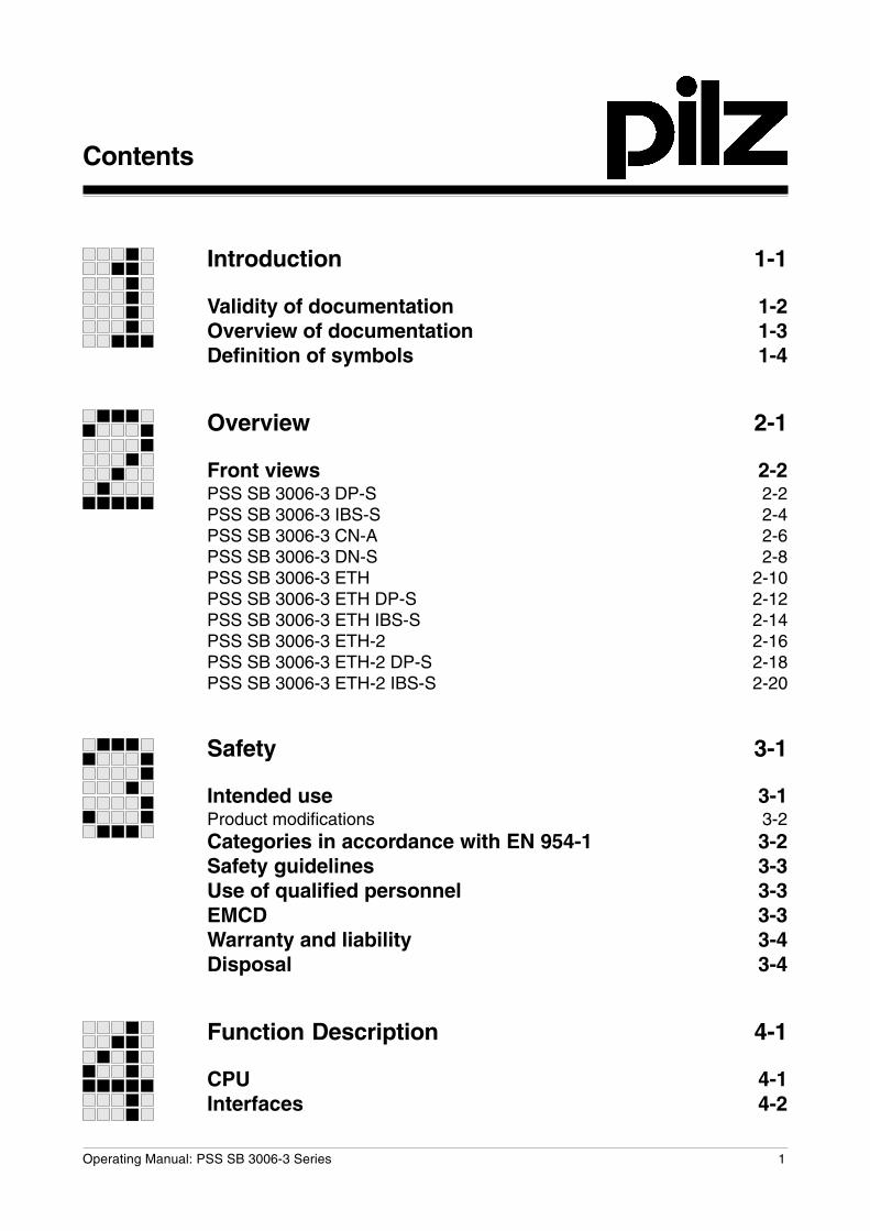
Introduction 1-1
Validity of documentation 1-2Overview of documentation 1-3Definition of symbols 1-4
Overview 2-1
Front views 2-2PSS SB 3006-3 DP-S 2-2PSS SB 3006-3 IBS-S 2-4PSS SB 3006-3 CN-A 2-6PSS SB 3006-3 DN-S 2-8PSS SB 3006-3 ETH 2-10PSS SB 3006-3 ETH DP-S 2-12PSS SB 3006-3 ETH IBS-S 2-14PSS SB 3006-3 ETH-2 2-16PSS SB 3006-3 ETH-2 DP-S 2-18PSS SB 3006-3 ETH-2 IBS-S 2-20
Safety 3-1
Intended use 3-1Product modifications 3-2Categories in accordance with EN 954-1 3-2Safety guidelines 3-3Use of qualified personnel 3-3EMCD 3-3Warranty and liability 3-4Disposal 3-4
Function Description 4-1
CPU 4-1Interfaces 4-2
Contents
Contents
2 Operating Manual: PSS SB 3006-3 Series
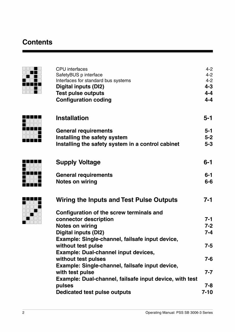
CPU interfaces 4-2SafetyBUS p interface 4-2Interfaces for standard bus systems 4-2Digital inputs (DI2) 4-3Test pulse outputs 4-4Configuration coding 4-4
Installation 5-1
General requirements 5-1Installing the safety system 5-2Installing the safety system in a control cabinet 5-3
Supply Voltage 6-1
General requirements 6-1Notes on wiring 6-6
Wiring the Inputs and Test Pulse Outputs 7-1
Configuration of the screw terminals andconnector description 7-1Notes on wiring 7-2Digital inputs (DI2) 7-4Example: Single-channel, failsafe input device,without test pulse 7-5Example: Dual-channel input devices,without test pulses 7-6Example: Single-channel, failsafe input device,with test pulse 7-7Example: Dual-channel, failsafe input device, with testpulses 7-8Dedicated test pulse outputs 7-10
3Operating Manual: PSS SB 3006-3 Series
Interfaces 8-1
General requirements 8-1Programming device interface (“PG”) 8-2Programming device interface RS 232 8-3Programming device interface RS 485 8-4User interface (“USER”) 8-5User interface RS 232 8-6User interface RS 485 8-7SafetyBUS p interface (“SafetyBUS p”) 8-8Interfaces for standard bus connections 8-9
Operation and Maintenance 9-1
Commissioning 9-1Faults 9-1Display elements 9-2PSS functionality 9-2SafetyBUS p functionality 9-2Standard bus functionality 9-2Changing the battery 9-3
Technical Details 10-1
Appendix 11-1
Address of SafetyBUS p Club 11-1Changes in the documentation 11-1

Contents
4 Operating Manual: PSS SB 3006-3 Series
1-1Operating Manual: PSS SB 3006-3 Series
This operating manual explains the function and operation of theprogrammable safety system, describes the installation and providesguidelines on how to connect the inputs and test pulse outputs onprogrammable safety systems from the PSS SB 3006-3 series. A PSSfrom the PSS SB 3006-3 series is a 3rd generation programmable safetysystem.
For connection to SafetyBUS p, units are available with one SafetyBUS pinterface as well as two SafetyBUS p interfaces.This operating manual describes the programmable safety systems fromthe PSS SB 3006-3 series with one SafetyBUS p interface.
Different interfaces are available for connection to various non-safety-related standard bus systems, depending on the unit type. Theseinterfaces are described in separate operating manuals. The necessaryoperating manuals are supplied with the relevant unit types.
Please refer to the PSS-range manuals, in particular the information andrequirements stated in the “PSS-Range Safety Manual”, “FS SystemDescription”, “ST System Description” and also the “SafetyBUS pInstallation Manual” from the SafetyBUS p manual package.
You will need to be conversant with the information in these manuals inorder to fully understand this manual.
This documentation is intended for instruction and should be retained forfuture reference.
Introduction
Introduction
1-2 Operating Manual: PSS SB 3006-3 Series
Validity of documentation
This documentation is valid for the following programmable safety systemsfrom the PSS SB 3006-3 series:
• PSS SB 3006-3 DP-S from Version 1.0
• PSS SB 3006-3 IBS-S from Version 1.0
• PSS SB 3006-3 CN-A from Version 1.0
• PSS SB 3006-3 DN-S from Version 1.0
• PSS SB 3006-3 ETH from Version 1.0
• PSS SB 3006-3 ETH DP-S from Version 1.0
• PSS SB 3006-3 ETH IBS-S from Version 1.0
• PSS SB 3006-3 ETH-2 from Version 1.0
• PSS SB 3006-3 ETH-2 DP-S from Version 1.0
• PSS SB 3006-3 ETH-2 IBS-S from Version 1.0
It is valid until new documentation is published. The latest documentationis always enclosed with the unit.
1-3Operating Manual: PSS SB 3006-3 Series
Overview of documentation
1 IntroductionThe introduction is designed to familiarise you with the contents,structure and specific order of this manual.
2 OverviewThis chapter provides information on the most important features ofthe programmable safety systems.
3 SafetyThis chapter must be read as it contains important information onsafety regulations and intended use.
4 Function DescriptionThis chapter describes the individual components of theprogrammable safety systems: CPU, inputs and test pulse outputs.
5 InstallationThis chapter explains how to install the programmable safetysystems.
6 Supply Voltage
This chapter explains what you need to consider when connecting thesupply voltage.
7 Wiring the Inputs and Test Pulse OutputsThis chapter describes the safety-related wiring of the inputs and testpulse outputs.
8 InterfacesThis chapter describes the configuration of the available interfaces.
9 Operation and MaintenanceThis chapter explains how to commission the safety systems andadvises on what to do if a fault occurs.
10 Technical Details
11 Appendix
Introduction
1-4 Operating Manual: PSS SB 3006-3 Series
Definition of symbols
Information in this manual that is of particular importance can be identifiedas follows:
DANGER!
This warning must be heeded! It warns of a hazardous situation thatposes an immediate threat of serious injury and death and indicatespreventive measures that can be taken.
WARNING!
This warning must be heeded! It warns of a hazardous situation thatcould lead to serious injury and death and indicates preventivemeasures that can be taken.
CAUTION!
This refers to a hazard that can lead to a less serious or minor injury plusmaterial damage, and also provides information on preventive measuresthat can be taken.
NOTICEThis describes a situation in which the unit(s) could be damaged and alsoprovides information on preventive measures that can be taken.
INFORMATIONThis gives advice on applications and provides information on specialfeatures, as well as highlighting areas within the text that are of particularimportance.
2-1Operating Manual: PSS SB 3006-3 Series
Overview
A PSS from the PSS SB 3006-3 series is a complete programmable safetysystem in a single unit. The following are all integrated into the housing:
• Power supply
• CPU
• 6 integral on-board inputs
• 2 test pulse outputs
• Programming device interface(combined RS 232/RS 485 interface)
• User interface(combined RS 232/RS 485 interface)
• Interface for connection to SafetyBUS p
• Interface(s) for connection to various standard bus systems
The integral on-board inputs can be used to monitor local emergencystops or to trigger an I/O-Group start, for example. They are suitable forconnecting single or dual-channel input devices, with or without testpulses. The dedicated test pulse outputs are suitable for testing inputdevices.SafetyBUS p enables you to establish a safe decentralised network ofseveral programmable safety systems and/or to connect decentralisedmodules. The PSS can perform the function of a Management, Logic orInput/Output Device on SafetyBUS p.For non-safety-related applications, the PSS can be connected to variousstandard bus systems (e.g. Ethernet, PROFIBUS-DP, INTERBUS,ControlNet, DeviceNet). The bus interfaces that are available will dependon the unit type.
INFORMATION
• The standard bus interfaces are described in separate operatingmanuals. The necessary operating manuals are supplied with therelevant unit types.
• Drivers (standard function blocks) from the corresponding Pilz softwarepackage will be required in order to connect to the various standard bussystems.
Overview
2-2 Operating Manual: PSS SB 3006-3 Series
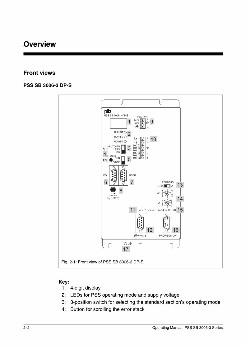
Key:1: 4-digit display2: LEDs for PSS operating mode and supply voltage3: 3-position switch for selecting the standard section’s operating mode4: Button for scrolling the error stack
Front views
PSS SB 3006-3 DP-S
Fig. 2-1: Front view of PSS SB 3006-3 DP-S
������
������
���
��
����������
��
���� ���
���
���
����������
������������������������������������������������
��
����
����
��
�
������
������������������
������������
������
�� ��
��
��� �
������
!���"#
���
�
!��"#�
����
�
�
�
�
�
��
�
�
��
��
�� ��
�
�� ����
��
���� � �
�
����
�������
2-3Operating Manual: PSS SB 3006-3 Series
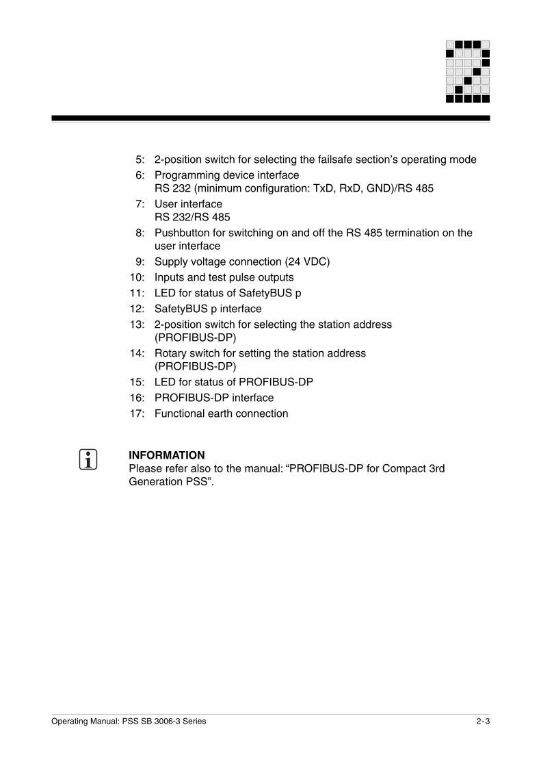
5: 2-position switch for selecting the failsafe section’s operating mode6: Programming device interface
RS 232 (minimum configuration: TxD, RxD, GND)/RS 4857: User interface
RS 232/RS 4858: Pushbutton for switching on and off the RS 485 termination on the
user interface9: Supply voltage connection (24 VDC)
10: Inputs and test pulse outputs11: LED for status of SafetyBUS p12: SafetyBUS p interface13: 2-position switch for selecting the station address
(PROFIBUS-DP)14: Rotary switch for setting the station address
(PROFIBUS-DP)15: LED for status of PROFIBUS-DP16: PROFIBUS-DP interface17: Functional earth connection
INFORMATIONPlease refer also to the manual: “PROFIBUS-DP for Compact 3rdGeneration PSS”.
Overview
2-4 Operating Manual: PSS SB 3006-3 Series
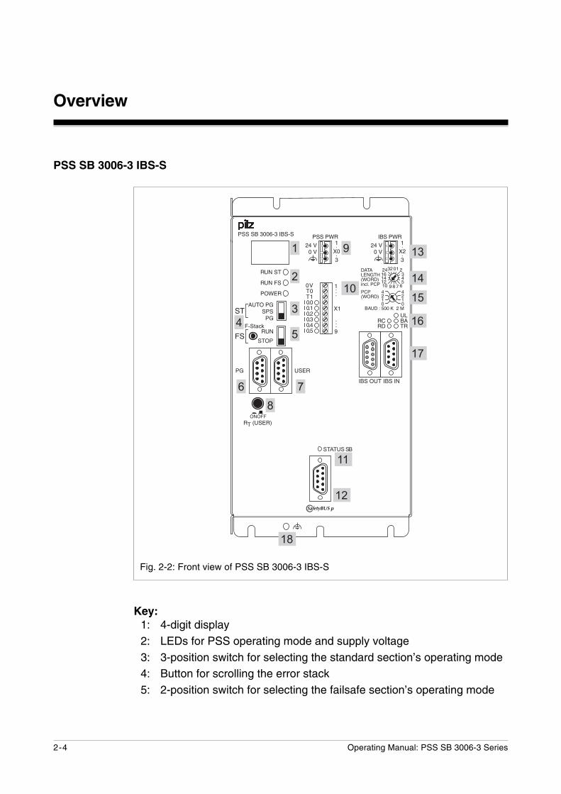
PSS SB 3006-3 IBS-S
Fig. 2-2: Front view of PSS SB 3006-3 IBS-S
Key:1: 4-digit display2: LEDs for PSS operating mode and supply voltage3: 3-position switch for selecting the standard section’s operating mode4: Button for scrolling the error stack5: 2-position switch for selecting the failsafe section’s operating mode
������
������
���
��
����������
�����
���
������������������������������������������������
��
����
����
�������������������
������������
��
�
������
������
�
�$��
��� ��
�$�����
����
��%
��������&� ���'
� � �����(����)*+,���$�
�
���"
���
#�
��
������
����
������
��������������
�
��
�
�
�
�� ����
��
���� � �
�
����
�������
��
��
��
��
��
��
������ ������
2-5Operating Manual: PSS SB 3006-3 Series
6: Programming device interfaceRS 232 (minimum configuration: TxD, RxD, GND)/RS 485
7: User interfaceRS 232/RS 485
8: Pushbutton for switching on and off the RS 485 termination on theuser interface
9: Supply voltage connection (24 VDC)10: Inputs and test pulse outputs11: LED for status of SafetyBUS p12: SafetyBUS p interface13: IBS supply voltage connection (24 VDC)14: Rotary switch for setting the whole data length
(process plus parameter data length)15: Rotary switch for setting the parameter data length (PCP) and the
transmission rate16: LED for status of Interbus17: Interbus interfaces
(IBS OUT, IBS IN)18: Functional earth connection
INFORMATIONPlease refer also to the manual: “INTERBUS for Compact 3rd GenerationPSS”.
Overview
2-6 Operating Manual: PSS SB 3006-3 Series
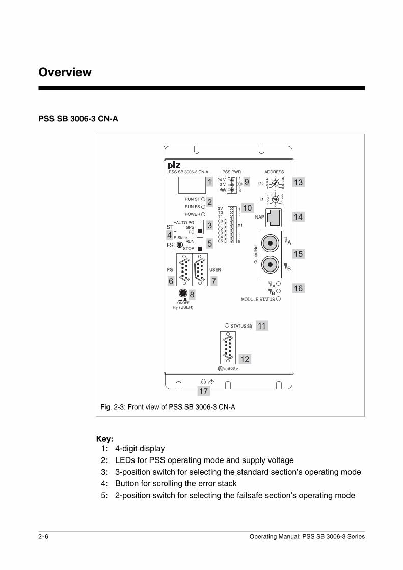
PSS SB 3006-3 CN-A
Fig. 2-3: Front view of PSS SB 3006-3 CN-A
Key:1: 4-digit display2: LEDs for PSS operating mode and supply voltage3: 3-position switch for selecting the standard section’s operating mode4: Button for scrolling the error stack5: 2-position switch for selecting the failsafe section’s operating mode
������
������
���
��
����������
�����
���
������������������������������������������������
��
����
����
��������������$��
������������
��
������
������ ������
!��"#�
����
�
�
!���"#
���
�� �
�
� �
�
%������� ����
�
�
��
�
�
�
�� ����
��
���� � �
�
����
�������
��
��
��
��
��
��
$-*./-,�0.
�
2-7Operating Manual: PSS SB 3006-3 Series
6: Programming device interfaceRS 232 (minimum configuration: TxD, RxD, GND)/RS 485
7: User interfaceRS 232/RS 485
8: Pushbutton for switching on and off the RS 485 termination on theuser interface
9: Supply voltage connection (24 VDC)10: Inputs and test pulse outputs11: LED for status of SafetyBUS p12: SafetyBUS p interface13: Rotary switch for setting the station address14: Connection for temporary bus access (Network Access Port)15: ControlNet interfaces (Channel A and Channel B)16: LEDs for communication error with ControlNet (Channel A and B)
and to display operation (module and PSS)17: Functional earth connection
INFORMATIONPlease refer also to the manual: “ControlNet Adapter for Compact 3rdGeneration PSS”.
Overview
2-8 Operating Manual: PSS SB 3006-3 Series
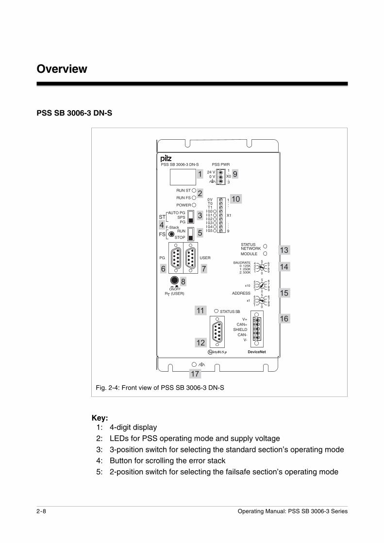
PSS SB 3006-3 DN-S
Fig. 2-4: Front view of PSS SB 3006-3 DN-S
Key:1: 4-digit display2: LEDs for PSS operating mode and supply voltage3: 3-position switch for selecting the standard section’s operating mode4: Button for scrolling the error stack5: 2-position switch for selecting the failsafe section’s operating mode
������
������
���
��
����������
�����
���
������������������������������������������������
��
����
����
������������������
������������
��
������
������
������
!��"#�
����
�
�
!���"#
���
�� �
�
� $ �
�(����$ ��
��
� ��� ���'����&�'����&�'����&
�"#�
����
�
�
�
�
��
�
�
�
�� ����
��
���� � �
�
����
�������
��
��
��
��
��
��
�
�� �������&%����
���������
2-9Operating Manual: PSS SB 3006-3 Series
6: Programming device interfaceRS 232 (minimum configuration: TxD, RxD, GND)/RS 485
7: User interfaceRS 232/RS 485
8: Pushbutton for switching on and off the RS 485 termination on theuser interface
9: Supply voltage connection (24 VDC)10: Inputs and test pulse outputs11: LED for status of SafetyBUS p12: SafetyBUS p interface13: LEDs for network and module status14: Rotary switch for setting the transmission rate15: Rotary switch for setting the station address16: Connection to DeviceNet17: Functional earth connection
INFORMATIONPlease refer also to the manual: “DeviceNet-Slave for Compact 3rdGeneration PSS”.

Overview
2-10 Operating Manual: PSS SB 3006-3 Series
PSS SB 3006-3 ETH
Fig. 2-5: Front view of PSS SB 3006-3 ETH
Key1: 4-digit display2: LEDs for PSS operating mode and supply voltage3: 3-position switch for selecting the standard section’s operating mode4: Button for scrolling the error stack5: 2-position switch for selecting the failsafe section’s operating mode
������
������
���
��
����������
�����
���
������������������������������������������������
��
����
����
������
����������������(
������������
������
��
��
�
�
�
��
�
�
��
�
�� ����
��
���� � �
�
����
�������
��(��������������� �������������������� ����������
��
��
2-11Operating Manual: PSS SB 3006-3 Series
6: Programming device interfaceRS 232 (minimum configuration: TxD, RxD, GND)/RS 485
7: User interfaceRS 232/RS 485
8: Pushbutton for switching on and off the RS 485 termination on theuser interface
9: Supply voltage connection (24 VDC)10: Inputs and test pulse outputs11: Labelling strip for Ethernet address12: ETHERNET interface with connection to ETHERNET via integrated
switch (2 free ports); LEDs on each port for- Status of network connection (LINK)- Status of data traffic (TRAFFIC)
13: LED for status of SafetyBUS p14: SafetyBUS p interface15 Functional earth connection
INFORMATIONPlease refer also to the manual: “Ethernet for Compact 3rd GenerationPSS”.

Overview
2-12 Operating Manual: PSS SB 3006-3 Series
Fig. 2-6: Front view of PSS SB 3006-3 ETH DP-S
Key1: 4-digit display2: LEDs for PSS operating mode and supply voltage3: 3-position switch for selecting the standard section’s operating mode4: Button for scrolling the error stack5: 2-position switch for selecting the failsafe section’s operating mode
PSS SB 3006-3 ETH DP-S
������
������
���
��
����������
��
���� ���
���
���
����������
������������������������������������������������
��
����
����
��
�
������
����������������(������
������������
������
�� �
��
������
!���"#
���
�
!��"#�
����
�
�
��� �
�
�
�
��
�
�
��
����
��
�
�� ����
��
���� � �
�
����
�������
��(��������������� �������������������� ����������
��
��
2-13Operating Manual: PSS SB 3006-3 Series
6: Programming device interfaceRS 232 (minimum configuration: TxD, RxD, GND)/RS 485
7: User interfaceRS 232/RS 485
8: Pushbutton for switching on and off the RS 485 termination on theuser interface
9: Supply voltage connection (24 VDC)10: Inputs and test pulse outputs11: Labelling strip for Ethernet address12: ETHERNET interface with connection to ETHERNET via integrated
switch (2 free ports); LEDs on each port for- Status of network connection (LINK)- Status of data traffic (TRAFFIC)
13: LED for status of SafetyBUS p14: SafetyBUS p interface15 2-position switch for selecting the station address
(PROFIBUS-DP)16: Rotary switch for setting the station address (PROFIBUS-DP)17: LED for status of PROFIBUS-DP18: PROFIBUS DP interface19: Functional earth connection
INFORMATIONPlease refer also to the manuals: “Ethernet for Compact 3rd GenerationPSS” and “PROFIBUS-DP for Compact 3rd Generation PSS”.
Overview
2-14 Operating Manual: PSS SB 3006-3 Series
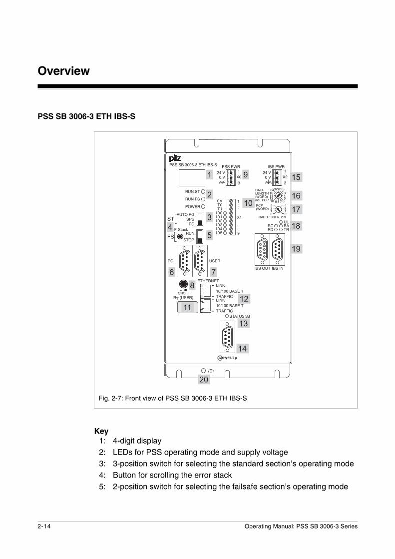
Fig. 2-7: Front view of PSS SB 3006-3 ETH IBS-S
������
������
���
��
����������
�����
���
������������������������������������������������
��
����
����
����������������(�������
������������
��
�
������
������
�
�$��
��� ��
�$�����
����
��%
��������&� ���'
� � �����(����)*+,���$�
�
���"
���
#�
��
������
����
������
��������������
�
��
�
�
��
�
�� ����
��
���� � �
�
����
�������
��(��������������� �������������������� ����������
��
��
��
��
��
�
��
������ ������
PSS SB 3006-3 ETH IBS-S
Key1: 4-digit display2: LEDs for PSS operating mode and supply voltage3: 3-position switch for selecting the standard section’s operating mode4: Button for scrolling the error stack5: 2-position switch for selecting the failsafe section’s operating mode
2-15Operating Manual: PSS SB 3006-3 Series
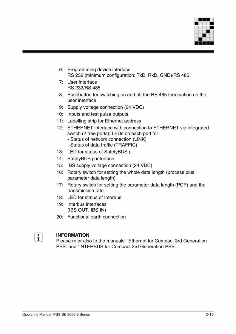
6: Programming device interfaceRS 232 (minimum configuration: TxD, RxD, GND)/RS 485
7: User interfaceRS 232/RS 485
8: Pushbutton for switching on and off the RS 485 termination on theuser interface
9: Supply voltage connection (24 VDC)10: Inputs and test pulse outputs11: Labelling strip for Ethernet address12: ETHERNET interface with connection to ETHERNET via integrated
switch (2 free ports); LEDs on each port for- Status of network connection (LINK)- Status of data traffic (TRAFFIC)
13: LED for status of SafetyBUS p14: SafetyBUS p interface15: IBS supply voltage connection (24 VDC)16: Rotary switch for setting the whole data length (process plus
parameter data length)17: Rotary switch for setting the parameter data length (PCP) and the
transmission rate18: LED for status of Interbus19: Interbus interfaces
(IBS OUT, IBS IN)20: Functional earth connection
INFORMATIONPlease refer also to the manuals: “Ethernet for Compact 3rd GenerationPSS” and “INTERBUS for Compact 3rd Generation PSS”.
Overview
2-16 Operating Manual: PSS SB 3006-3 Series
PSS SB 3006-3 ETH-2
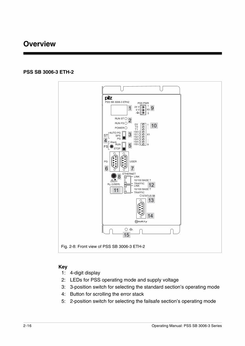
Fig. 2-8: Front view of PSS SB 3006-3 ETH-2
Key1: 4-digit display2: LEDs for PSS operating mode and supply voltage3: 3-position switch for selecting the standard section’s operating mode4: Button for scrolling the error stack5: 2-position switch for selecting the failsafe section’s operating mode
������
������
���
��
����������
�����
���
������������������������������������������������
��
����
����
������
����������������(��
������������
������
��
��
�
�
�
��
�
�
��
�
�� ����
��
���� � �
�
����
�������
��(��������������� �������������������� ����������
��
��
2-17Operating Manual: PSS SB 3006-3 Series
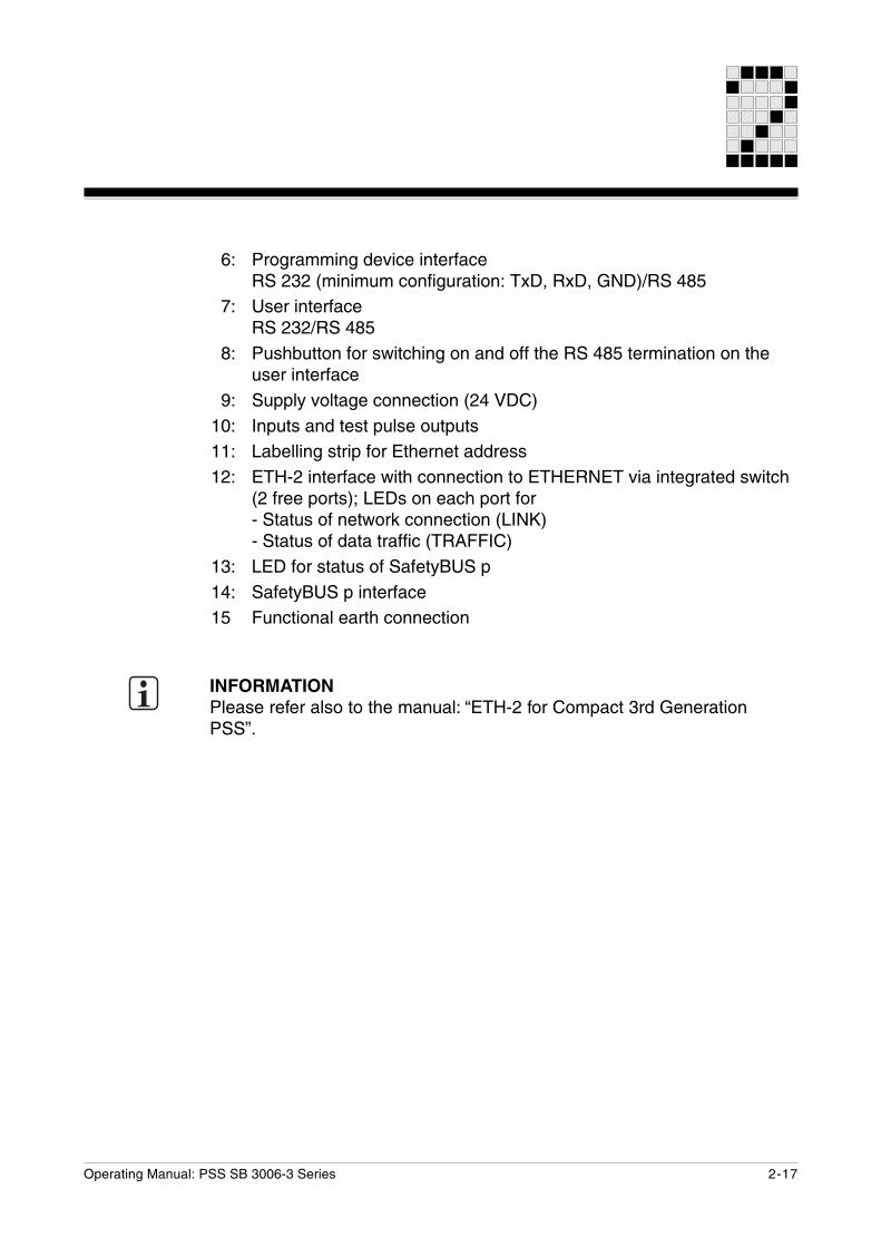
6: Programming device interfaceRS 232 (minimum configuration: TxD, RxD, GND)/RS 485
7: User interfaceRS 232/RS 485
8: Pushbutton for switching on and off the RS 485 termination on theuser interface
9: Supply voltage connection (24 VDC)10: Inputs and test pulse outputs11: Labelling strip for Ethernet address12: ETH-2 interface with connection to ETHERNET via integrated switch
(2 free ports); LEDs on each port for- Status of network connection (LINK)- Status of data traffic (TRAFFIC)
13: LED for status of SafetyBUS p14: SafetyBUS p interface15 Functional earth connection
INFORMATIONPlease refer also to the manual: “ETH-2 for Compact 3rd GenerationPSS”.
Overview
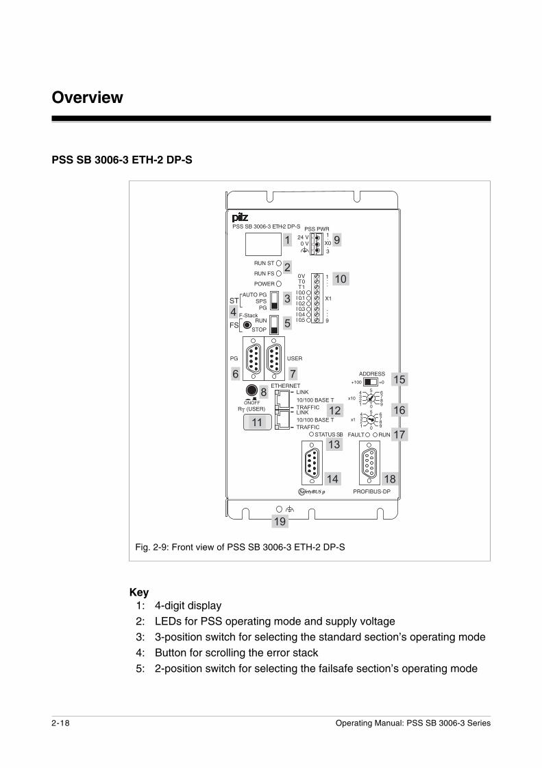
2-18 Operating Manual: PSS SB 3006-3 Series
PSS SB 3006-3 ETH-2 DP-S
Fig. 2-9: Front view of PSS SB 3006-3 ETH-2 DP-S
Key1: 4-digit display2: LEDs for PSS operating mode and supply voltage3: 3-position switch for selecting the standard section’s operating mode4: Button for scrolling the error stack5: 2-position switch for selecting the failsafe section’s operating mode
������
������
���
��
����������
��
���� ���
���
���
����������
������������������������������������������������
��
����
����
��
�
������
����������������(��������
������������
������
�� �
��
������
!���"#
���
�
!��"#�
����
�
�
��� �
�
�
�
��
�
�
��
����
��
�
�� ����
��
���� � �
�
����
�������
��(��������������� �������������������� ����������
��
��
2-19Operating Manual: PSS SB 3006-3 Series
6: Programming device interfaceRS 232 (minimum configuration: TxD, RxD, GND)/RS 485
7: User interfaceRS 232/RS 485
8: Pushbutton for switching on and off the RS 485 termination on theuser interface
9: Supply voltage connection (24 VDC)10: Inputs and test pulse outputs11: Labelling strip for Ethernet address12: ETH-2 interface with connection to ETHERNET via integrated switch
(2 free ports); LEDs on each port for- Status of network connection (LINK)- Status of data traffic (TRAFFIC)
13: LED for status of SafetyBUS p14: SafetyBUS p interface15 2-position switch for selecting the station address
(PROFIBUS-DP)16: Rotary switch for setting the station address (PROFIBUS-DP)17: LED for status of PROFIBUS-DP18: PROFIBUS DP interface19: Functional earth connection
INFORMATIONPlease refer also to the manuals: “ETH-2 for Compact 3rd GenerationPSS” and “PROFIBUS-DP for Compact 3rd Generation PSS”.

Overview
2-20 Operating Manual: PSS SB 3006-3 Series
PSS SB 3006-3 ETH-2 IBS-S
Fig. 2-10: Front view of PSS SB 3006-3 ETH-2 IBS-S
Key1: 4-digit display2: LEDs for PSS operating mode and supply voltage3: 3-position switch for selecting the standard section’s operating mode4: Button for scrolling the error stack5: 2-position switch for selecting the failsafe section’s operating mode
������
������
���
��
����������
�����
���
������������������������������������������������
��
����
����
����������������(���������
������������
��
�
������
������
�
�$��
��� ��
�$�����
����
��%
��������&� ���'
� � �����(����)*+,���$�
�
���"
���
#�
��
������
����
������
��������������
�
��
�
�
��
�
�� ����
��
���� � �
�
����
�������
��(��������������� �������������������� ����������
��
��
��
��
��
�
��
������ ������
2-21Operating Manual: PSS SB 3006-3 Series
6: Programming device interfaceRS 232 (minimum configuration: TxD, RxD, GND)/RS 485
7: User interfaceRS 232/RS 485
8: Pushbutton for switching on and off the RS 485 termination on theuser interface
9: Supply voltage connection (24 VDC)10: Inputs and test pulse outputs11: Labelling strip for Ethernet address12: ETH-2 interface with connection to ETHERNET via integrated switch
(2 free ports); LEDs on each port for- Status of network connection (LINK)- Status of data traffic (TRAFFIC)
13: LED for status of SafetyBUS p14: SafetyBUS p interface15: IBS supply voltage connection (24 VDC)16: Rotary switch for setting the whole data length (process plus
parameter data length)17: Rotary switch for setting the parameter data length (PCP) and the
transmission rate18: LED for status of Interbus19: Interbus interfaces
(IBS OUT, IBS IN)20: Functional earth connection
INFORMATIONPlease refer also to the manuals: “ETH-2 for Compact 3rd GenerationPSS” and “INTERBUS for Compact 3rd Generation PSS”.
Overview
2-22 Operating Manual: PSS SB 3006-3 Series
Notes
3-1Operating Manual: PSS SB 3006-3 Series
Safety
Intended use
Programmable safety systems from the PSS SB 3006-3 series areintended for use as follows:
• Safety-related applicationsin the failsafe section of the PSS, including connection to SafetyBUS p
• Non-safety-related applicationsin the standard section of the PSS, including connection to standard bussystems.
INFORMATIONThe following system software is required in order to program the safetysystems:
• PSS SW PG from Version 5.1 or PSS WIN-PRO from Version 1.1.0 for- PSS SB 3006-3 DP-S- PSS SB 3006-3 IBS-S- PSS SB 3006-3 ETH- PSS SB 3006-3 ETH DP-S- PSS SB 3006-3 ETH IBS-S
• PSS SW PG from Version 5.4 or PSS WIN-PRO from Version 1.1.2 for- PSS SB 3006-3 CN-A- PSS SB 3006-3 DN-S
• PSS WIN-PRO from Version 1.3.0 for- PSS SB 3006-3 ETH-2- PSS SB 3006-3 ETH-2 DP-S- PSS SB 3006-3 ETH-2 IBS-S
INFORMATIONDrivers (standard function blocks) from the corresponding Pilz softwarepackage will be required in order to connect to the various standard bussystems:
• ST-SB-DP-S: Driver for PROFIBUS-DP Slave
• ST-SB-ControlNet: Driver for ControlNet Adapter
• ST-SB-DN-S: Driver for DeviceNet Slave
• ST-SB-Ethernet: Driver for Ethernet (not for ETH-2)
• ST-SB-IBS-S: Driver for INTERBUS Slave
Safety
3-2 Operating Manual: PSS SB 3006-3 Series
For the standard bus interface ETH-2, the Ethernet Configurator isavailable as part of the PSS WIN-PRO system software from Version1.3.0.
The following is deemed improper use:
• Any component, technical or electrical modification to the safety system
• Use of the safety system outside the areas described in this manual
• Use of the safety system outside the documented technical details (seechapter entitled “Technical Details”).
Intended use includes making the installation EMC-compliant. Pleaseobserve the guidelines given in this manual and in the “Safety Manual” forthe PSS-range. The „Safety Manual“ also includes check lists designed tohelp you with the safety-related planning, construction and operation of aplant.
Product modifications
Details of the changes made to a unit from one version to the next aredescribed in the “Product Modifications” file. This file can be found on the“Documentation PSS-Range/SafetyBUS p” CD or on the Internet(www.pilz.com) with the unit’s documentation.
Categories in accordance with EN 954-1
WARNING!
Please note: To achieve the corresponding category or requirement class,the whole system including all safety-related components (parts, devices,user program etc.) must be included in the assessment. For this reason,Pilz cannot accept liability for the correct classification into a category orrequirement class.
3-3Operating Manual: PSS SB 3006-3 Series
Digital inputs (DI2)
Depending on the application area and its respective regulations, the PSSmay be used without test pulses for applications up to category 3 in accordance with EN 954-1 (03/97). The possibility of a short circuitoccurring in the external wiring between different inputs or to L+ must beeliminated through appropriate wiring.
Test pulses must be used for category 4 applications (for connectionexamples please see Chapter 7, “Wiring the Inputs and Test PulseOutputs”).
Safety guidelines
Failure to keep to these guidelines will render all warranty and liabilityclaims invalid:
• All health and safety / accident prevention regulations for the particulararea of application must be observed.
• Before using the unit it is necessary to perform a safety assessment inaccordance with the Machinery Directive 98/37/EC.
Use of qualified personnel
The safety system may only be assembled, installed, programmed,commissioned, operated, maintained and decomissioned by qualifiedpersonnel. Qualified personnel are people who, because they are:
• Qualified electrical engineers and
• Have received training from qualified electrical engineers,
are suitably experienced to operate devices, systems, plant and machineryin accordance with the general standards and guidelines for safetytechnology.

Safety
3-4 Operating Manual: PSS SB 3006-3 Series
EMCD
The safety system is designed for use in an industrial environment.Interference may occur if used within a domestic environment.
Warranty and liability
All claims to warranty and liability will be rendered invalid if:
• The safety system was used contrary to the purpose for which it wasintended
• Damage can be attributed to not having followed the guidelines in themanual
• Operating personnel are not suitably qualified.
• Any type of modification has been made (e.g. exchanging componentson the PCB boards, soldering work etc.).
Disposal
The programmable safety system must be disposed of properly when itreaches the end of its service life.
Operating Manual: PSS SB 3006-3 Series 4-1
Function Description
CPU
The CPU controls the test pulse outputs, reads the inputs and processes /stores the user program and variable data. The failsafe section is designedto be multi-channel, i.e. different CPUs process the user programindependently.A four-digit display and several LEDs provide information on the status ofthe safety system and indicate any errors.
Function Description
4-2 Operating Manual: PSS SB 3006-3 Series
Interfaces
CPU interfaces
The CPU of each programmable safety system in the PSS SB 3006-3series provides the following interfaces:
• Programming device interfaceCombined RS 232 interface (minimum configuration: TxD, RxD, GND)/RS 485
• User interfaceCombined RS 232/RS 485 interface
For further information please refer to the “System Manual for thePSS-Range”.
SafetyBUS p interface
Each programmable safety system in the PSS SB 3006-3 series has aSafetyBUS p interface.PSS SB2 3006-3 units have a second SafetyBUS p interface. The secondSafetyBUS p interface can be used to divide up large plants. This can helpto optimise the reaction time.
For further information on SafetyBUS p, please refer to the “SystemManual for SafetyBUS p”.
Interfaces for standard bus systems
Different interfaces are available for connection to various standard bussystems, depending on the unit type. The standard bus interfaces aredescribed in separate operating manuals. The necessary operatingmanuals are supplied with the relevant unit types.
Operating Manual: PSS SB 3006-3 Series 4-3
Digital inputs (DI2)
All programmable safety systems in the PSS SB 3006-3 series have sixintegral on-board inputs, which are suitable for connecting single and dual-channel input devices, with or without test pulses. Input signals must showa “High” (“1” signal) of 24 VDC (+15 ... +30 VDC) and a “Low” (“0” signal)of 0 VDC (-3 ... +5 VDC).
LEDs are used as status indicators. An LED lights up as soon as a “1”signal is present at the input. All inputs have input filters.
Internal diagnostic circuitry checks the function of the inputs, including theinput filter. If an error occurs, the PSS will switch to a STOP condition andoutput a message to the CPU display. In addition, all the decentralisedoutputs in the I/O-Groups assigned to the PSS Logic Device will beswitched off (see also “SafetyBUS p System Description”).
Where test pulses are not used, inputs with single-channel input devicescan be used in applications up to and including Category 2 in accordancewith EN 954-1; in the case of dual-channel input devices, this extends toCategory 3 applications. The device should be suitably wired to eliminatethe risk of a short circuit in the external wiring between the different inputsand also between the PSS supply and any bus interface.
Test pulses must be used for applications with single-channel inputdevices above Category 2 and for applications with dual-channel inputdevices above Category 3. Connection examples can be found in Chapter 7of this manual, “Wiring the Inputs and Test Pulse Outputs”.
Function Description
4-4 Operating Manual: PSS SB 3006-3 Series
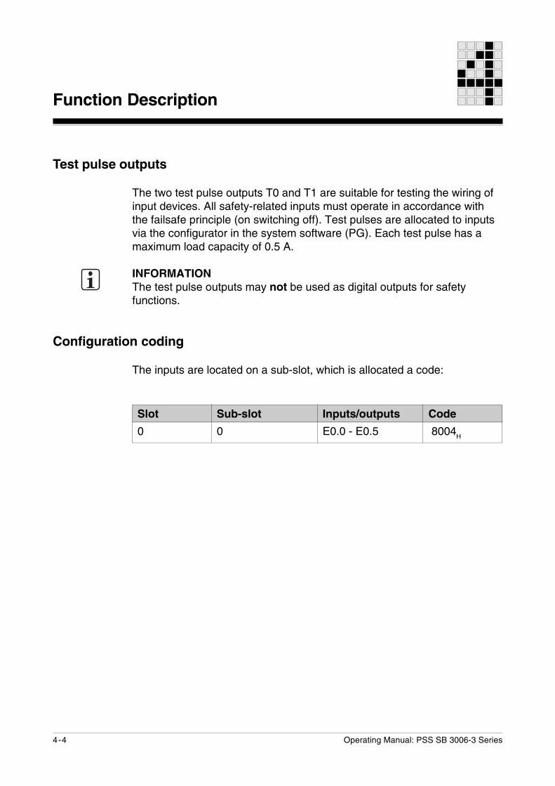
Slot
0
Sub-slot
0
Inputs/outputs
E0.0 - E0.5
Code
8004H
Test pulse outputs
The two test pulse outputs T0 and T1 are suitable for testing the wiring ofinput devices. All safety-related inputs must operate in accordance withthe failsafe principle (on switching off). Test pulses are allocated to inputsvia the configurator in the system software (PG). Each test pulse has amaximum load capacity of 0.5 A.
INFORMATIONThe test pulse outputs may not be used as digital outputs for safetyfunctions.
Configuration coding
The inputs are located on a sub-slot, which is allocated a code:
5-1Operating Manual: PSS SB 3006-3 Series
General requirements
Please note the following:
• The safety system should be installed in an enclosure, e.g. controlcabinet, that conforms to the protection class required for theenvironment.
• When installing the system in an enclosure such as a control cabinet, theenvironmental data for the safety system must be taken into account.Details can be found in the chapter entitled “Technical Details”.
• Ensure there is sufficient ventilation to prevent heat building up within thecontrol cabinet. Please note the ambient temperature of 0 ... 60 °C.
• In extreme ambient conditions, additional measures may be required inorder to keep within the prescribed value range.
• Use low interference panel lighting for inside the control cabinet.
• The safety system must be installed in such a way that there is adequateprotection against buttons and switches being operated unintentionally.
CAUTION!
Damage due to electrostatic discharge!Electrostatic discharge can damage components on the safety system.Ensure against discharge before touching the PSS, e.g. by touching anearthed, conductive surface or by wearing an earthed armband.
Installation
Installation
5-2 Operating Manual: PSS SB 3006-3 Series
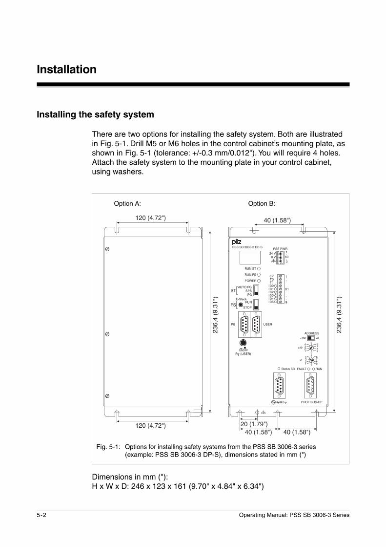
Fig. 5-1: Options for installing safety systems from the PSS SB 3006-3 series(example: PSS SB 3006-3 DP-S), dimensions stated in mm (")
������
������
���
��
����������
��
��� �
!�
���� ���
���
���
����������
������
������������������������������������������������
��
����
����
!���"#�
����
�
�
�"#�
����
�
�
������
������������������
������������
������
�������"�1��������#1�
���2�������1�
�������#1�
�������#1�
���2�������1�
�������"�1�
�� ����
��
���� � �
����
�������
������"�1�
Installing the safety system
There are two options for installing the safety system. Both are illustratedin Fig. 5-1. Drill M5 or M6 holes in the control cabinet’s mounting plate, asshown in Fig. 5-1 (tolerance: +/-0.3 mm/0.012"). You will require 4 holes.Attach the safety system to the mounting plate in your control cabinet,using washers.
Option A: Option B:
Dimensions in mm ("):H x W x D: 246 x 123 x 161 (9.70" x 4.84" x 6.34")
5-3Operating Manual: PSS SB 3006-3 Series
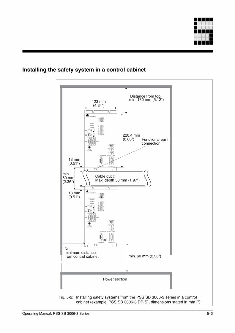
Installing the safety system in a control cabinet
Fig. 5-2: Installing safety systems from the PSS SB 3006-3 series in a controlcabinet (example: PSS SB 3006-3 DP-S), dimensions stated in mm (")
���33�����1�
�-3)*)343�5)6.7*+08/-3�+-*./-,�+79)*0.
�)6.7*+0�8/-3�.-:3)*������33������1�
�-;0/�60+.)-*
3)*�����33������1�
$79,0�54+.'%7!��50:.<����33�����"1�
������33�#��#1�
���33�����1�
�4*+.)-*7,�07/.<+-**0+.)-*
����33���#�1�
3)*����33�����1�
������
������
���
��
����������
��
��� �
!�
���� ���
���
���
����������
������
������������������������������������������������
��
����
����
!���"#�
����
�
�
�"#�
����
�
�
������
������������������
������������
��
������
������
���
��
����������
��
��� �
!�
���� ���
���
���
����������
������
������������������������������������������������
��
����
����
!���"#�
����
�
�
�"#�
����
�
�
������
������������������
������������
������
������
�� ����
��
���� � �
����
�������
�� ����
��
���� � �
����
�������
Installation
5-4 Operating Manual: PSS SB 3006-3 Series
Notes
Operating Manual: PSS SB 3006-3 Series 6-1
General requirements
Please note the following:
• When selecting the power supply, please refer to the requirements statedunder “Technical Details”.
INFORMATIONWhen test pulse outputs are used, the output circuits are designed toguarantee maximum safety. To achieve this, extensive tests are carriedout internally. If the supply voltage is interrupted during a test function,the relevant test pulse output will be deemed to be defective.The normal error reaction will occur: the PSS switches to a STOPcondition.Remedy: buffer the PSS supply voltage.
• Overvoltage and spikes of interference outside the specifications candamage the PSS. In this case the PSS will switch to a safe condition.You should therefore ensure that appropriate EMC measures are taken.
• To achieve the lowest possible residual ripple (< ± 1.2 V), werecommend that you install a three-phase bridge rectifier or regulatedsupply.
• The fuse between an external power supply and the PSS protects theexternal supply. The size of the fuse will depend on the specification ofthe external power supply, the cable cross section and on localregulations.
WARNING!
Electric shock!Safe electrical isolation must be ensured for the external 24 V supply.Failure to do so could result in electric shock. Power supplies must conformto EN 60950, 03/97, section 2.3, EN 60742, 9/95 or EN 50178, 10/97.
Supply Voltage
Supply Voltage
6-2 Operating Manual: PSS SB 3006-3 Series
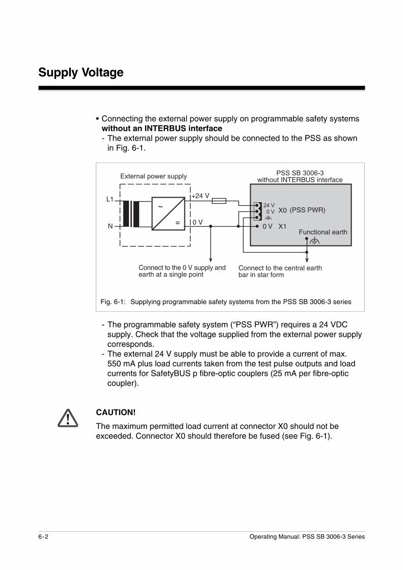
• Connecting the external power supply on programmable safety systemswithout an INTERBUS interface- The external power supply should be connected to the PSS as shown
in Fig. 6-1.
Fig. 6-1: Supplying programmable safety systems from the PSS SB 3006-3 series
�
�
��
�
����
���
��
��� ��
$-**0+.�.-�.<0�+0*./7,�07/.<97/�)*�6.7/�8-/3
$-**0+.�.-�.<0�����64::,=�7*507/.<�7.�7�6)*>,0�:-)*.
�������� ���������
��������
�������������;).<-4.����������)*.0/87+0
�!���!
�4*+.)-*7,�07/.<
- The programmable safety system (“PSS PWR”) requires a 24 VDCsupply. Check that the voltage supplied from the external power supplycorresponds.
- The external 24 V supply must be able to provide a current of max.550 mA plus load currents taken from the test pulse outputs and loadcurrents for SafetyBUS p fibre-optic couplers (25 mA per fibre-opticcoupler).
CAUTION!
The maximum permitted load current at connector X0 should not beexceeded. Connector X0 should therefore be fused (see Fig. 6-1).
Operating Manual: PSS SB 3006-3 Series 6-3
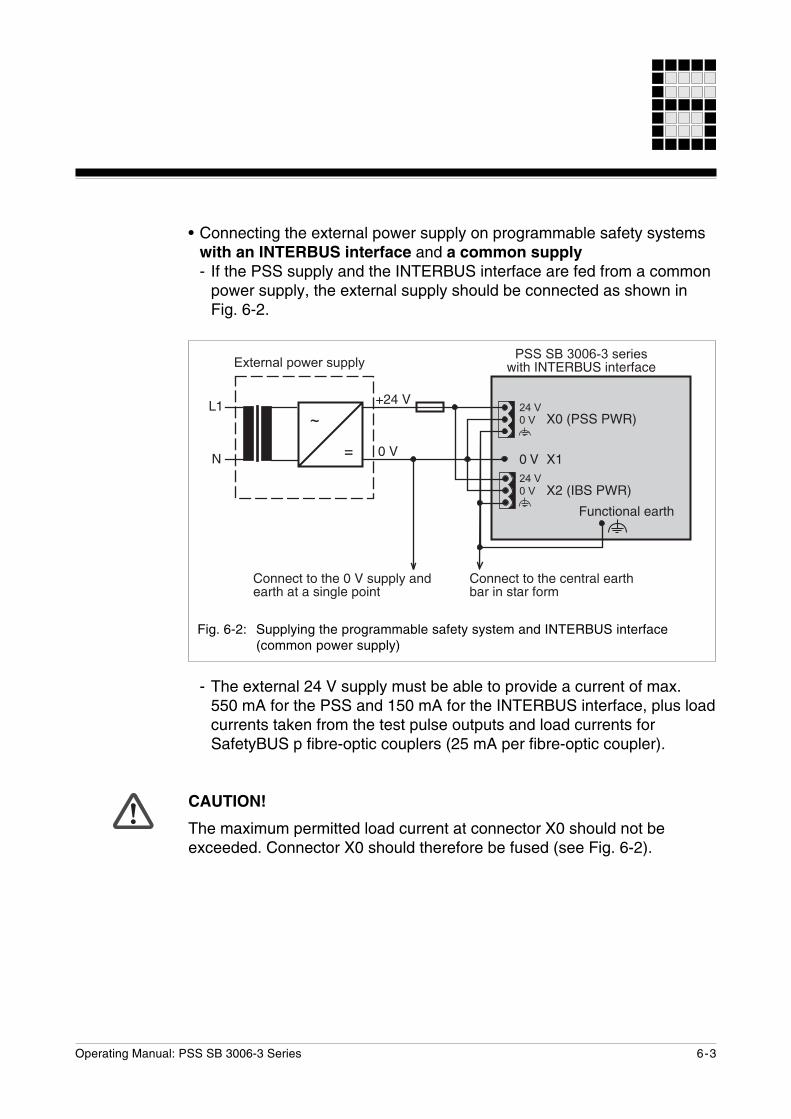
- The external 24 V supply must be able to provide a current of max.550 mA for the PSS and 150 mA for the INTERBUS interface, plus loadcurrents taken from the test pulse outputs and load currents forSafetyBUS p fibre-optic couplers (25 mA per fibre-optic coupler).
CAUTION!
The maximum permitted load current at connector X0 should not beexceeded. Connector X0 should therefore be fused (see Fig. 6-2).
�
�
��
�
����
���
��������������������;).<����������)*.0/87+0�������� ���������
�����������
�����������
��� ��
�4*+.)-*7,�07/.<
$-**0+.�.-�.<0�����64::,=�7*507/.<�7.�7�6)*>,0�:-)*.
$-**0+.�.-�.<0�+0*./7,�07/.<97/�)*�6.7/�8-/3
�!���!
�!���!
Fig. 6-2: Supplying the programmable safety system and INTERBUS interface(common power supply)
• Connecting the external power supply on programmable safety systemswith an INTERBUS interface and a common supply- If the PSS supply and the INTERBUS interface are fed from a common
power supply, the external supply should be connected as shown inFig. 6-2.
Supply Voltage
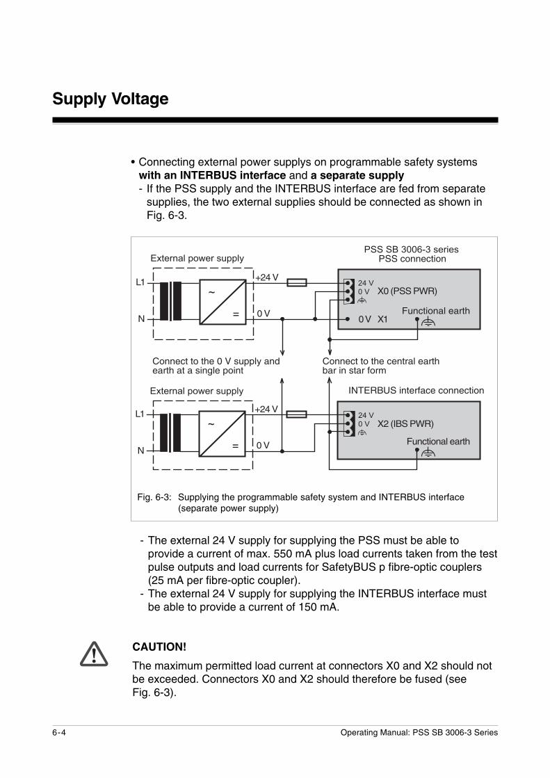
6-4 Operating Manual: PSS SB 3006-3 Series
- The external 24 V supply for supplying the PSS must be able toprovide a current of max. 550 mA plus load currents taken from the testpulse outputs and load currents for SafetyBUS p fibre-optic couplers(25 mA per fibre-optic coupler).
- The external 24 V supply for supplying the INTERBUS interface mustbe able to provide a current of 150 mA.
CAUTION!
The maximum permitted load current at connectors X0 and X2 should notbe exceeded. Connectors X0 and X2 should therefore be fused (seeFig. 6-3).
• Connecting external power supplys on programmable safety systemswith an INTERBUS interface and a separate supply- If the PSS supply and the INTERBUS interface are fed from separate
supplies, the two external supplies should be connected as shown inFig. 6-3.
�
�
��
�
����
���
������������������������+-**0+.)-*�������� ���������
�����������
������������
�
��
�
����
���
�������� ���������
�!���!
���������)*.0/87+0�+-**0+.)-*
�����������
��� ���4*+.)-*7,�07/.<
$-**0+.�.-�.<0�����64::,=�7*507/.<�7.�7�6)*>,0�:-)*.
$-**0+.�.-�.<0�+0*./7,�07/.<97/�)*�6.7/�8-/3
�!���!
�4*+.)-*7,�07/.<
Fig. 6-3: Supplying the programmable safety system and INTERBUS interface(separate power supply)
Operating Manual: PSS SB 3006-3 Series 6-5
• NOTICEThere must be no direct connection between “N” and the 0 V output onthe external power supply or external power supplies!
• Connect together the 0V connections on all the 24 V power supplies andearth the 0 V mains at a single point. The connection of the0 V supply to the central earth bar or earth fault monitor must be inaccordance with relevant national regulations (e.g. EN 60204-1, NFPA79:17-7, NEC: Article 250).
INFORMATIONIf the inputs on the PSS are being used with test pulses, connect L- on theinput device supply to the 0 V terminal for the supply voltage (connectorX0). Please refer to Chapter 7, “Wiring the Inputs and Test Pulse Outputs”.
Supply Voltage
6-6 Operating Manual: PSS SB 3006-3 Series
Notes on wiring
• Minimum range for cable cross sections on field connection terminals inmm2, in accordance with EN 61131-2, 07/00:- Power supply: 1.5 (AWG16) ... 2.5 (AWG12)- Functional earth: 1.5 (AWG16) ... 2.5 (AWG12)
• Use copper wiring.
• The torque setting on the terminals should be 0.5 … 0.6 Nm.
Operating Manual: PSS SB 3006-3 Series 7-1
Wiring the Inputs and Test Pulse Outputs
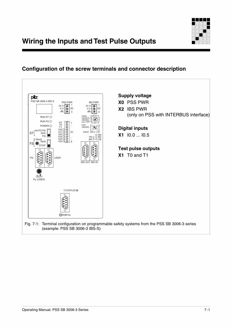
Configuration of the screw terminals and connector description
Fig. 7-1: Terminal configuration on programmable safety systems from the PSS SB 3006-3 series(example: PSS SB 3006-3 IBS-S)
Supply voltageX0 PSS PWRX2 IBS PWR
(only on PSS with INTERBUS interface)
Digital inputsX1 I0.0 ... I0.5
Test pulse outputsX1 T0 and T1
������
������
���
��
����������
�����
���
������������������������������������������������
��
����
����
�������������������
������������
������
������
���
���$��
�$�����
����
��%
��������&� ���'
� � �����(����)*+,���$�
�
���"
���
#�
��
������
����
������
�������������
�� ����
��
���� � �
����
�������
������ ������

Wiring the Inputs and Test Pulse Outputs
7-2 Operating Manual: PSS SB 3006-3 Series
Notes on wiring
Where safety-related applications are concerned, it is essential that shortcircuits and open circuits are unable to cause a hazardous condition withina plant.
The way in which this is done will depend on the degree of hazard withinthe plant itself, the switching frequency of the input devices and the levelof safety of the input devices and actuators. You should assess thesepoints in conjunction with the relevant standards or approvals body (e.g.BG or TÜV).
Please observe the following when wiring:
• Earthing:- Connect the housing to the central earth bar.- A cable cross section of at least 2.5 mm2 should be used.- Connections should be kept as short as possible.
• Open circuits, short circuits and earth faults:- In principle it is possible to eliminate short circuits between signals
within electrically-enclosed areas and also outside electrically-enclosedareas when the signals are conducted in different multicore cables.However, all components must meet the relevant regulations inaccordance with EN, DIN and VDE.
- Open circuits and earth faults cannot be eliminated.- On multi-channel input devices with frequent operation, short circuits
and open circuits can be detected via feasibility checks in the controlprogram.
- The input test on the programmable safety system uses test pulses toenable the system’s operating program to carry out a test to detectopen circuits and short circuits.
NOTICEPlease read the description that accompanies the connectionexamples! The connection examples can be found on the followingpages.
Operating Manual: PSS SB 3006-3 Series 7-3
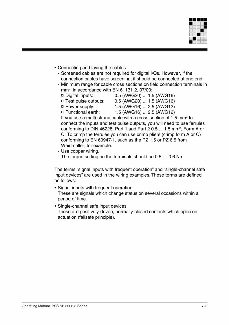
• Connecting and laying the cables- Screened cables are not required for digital I/Os. However, if the
connection cables have screening, it should be connected at one end.- Minimum range for cable cross sections on field connection terminals in
mm2, in accordance with EN 61131-2, 07/00:¤ Digital inputs: 0.5 (AWG20) ... 1.5 (AWG16)¤ Test pulse outputs: 0.5 (AWG20) ... 1.5 (AWG16)¤ Power supply: 1.5 (AWG16) ... 2.5 (AWG12)¤ Functional earth: 1.5 (AWG16) ... 2.5 (AWG12)
- If you use a multi-strand cable with a cross section of 1.5 mm2 toconnect the inputs and test pulse outputs, you will need to use ferrulesconforming to DIN 46228, Part 1 and Part 2 0.5 ... 1.5 mm2, Form A orC. To crimp the ferrules you can use crimp pliers (crimp form A or C)conforming to EN 60947-1, such as the PZ 1.5 or PZ 6.5 fromWeidmüller, for example.
- Use copper wiring.- The torque setting on the terminals should be 0.5 … 0.6 Nm.
The terms “signal inputs with frequent operation” and “single-channel safeinput devices” are used in the wiring examples. These terms are definedas follows:
• Signal inputs with frequent operationThese are signals which change status on several occasions within aperiod of time.
• Single-channel safe input devicesThese are positively-driven, normally-closed contacts which open onactuation (failsafe principle).
Wiring the Inputs and Test Pulse Outputs
7-4 Operating Manual: PSS SB 3006-3 Series
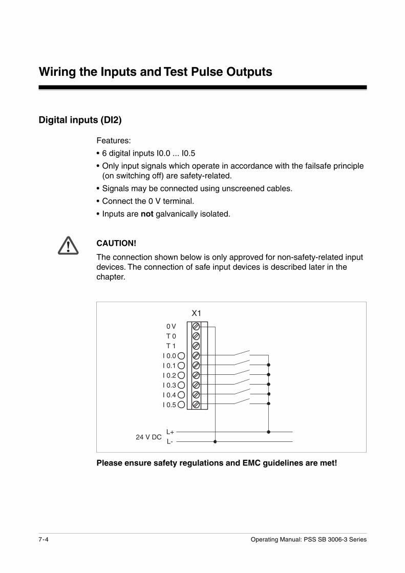
Digital inputs (DI2)
Features:
• 6 digital inputs I0.0 ... I0.5
• Only input signals which operate in accordance with the failsafe principle(on switching off) are safety-related.
• Signals may be connected using unscreened cables.
• Connect the 0 V terminal.
• Inputs are not galvanically isolated.
CAUTION!
The connection shown below is only approved for non-safety-related inputdevices. The connection of safe input devices is described later in thechapter.
Please ensure safety regulations and EMC guidelines are met!
������$� ��
��
������������������������������������������������
Operating Manual: PSS SB 3006-3 Series 7-5
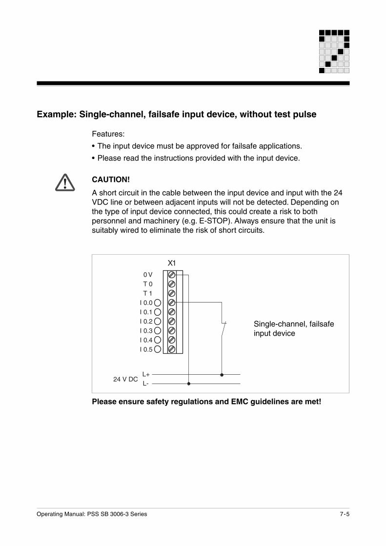
Example: Single-channel, failsafe input device, without test pulse
Features:
• The input device must be approved for failsafe applications.
• Please read the instructions provided with the input device.
CAUTION!
A short circuit in the cable between the input device and input with the 24VDC line or between adjacent inputs will not be detected. Depending onthe type of input device connected, this could create a risk to bothpersonnel and machinery (e.g. E-STOP). Always ensure that the unit issuitably wired to eliminate the risk of short circuits.
Please ensure safety regulations and EMC guidelines are met!
������$� ��
������������������������������������������������
��
Single-channel, failsafeinput device
Wiring the Inputs and Test Pulse Outputs
7-6 Operating Manual: PSS SB 3006-3 Series
Please ensure safety regulations and EMC guidelines are met!
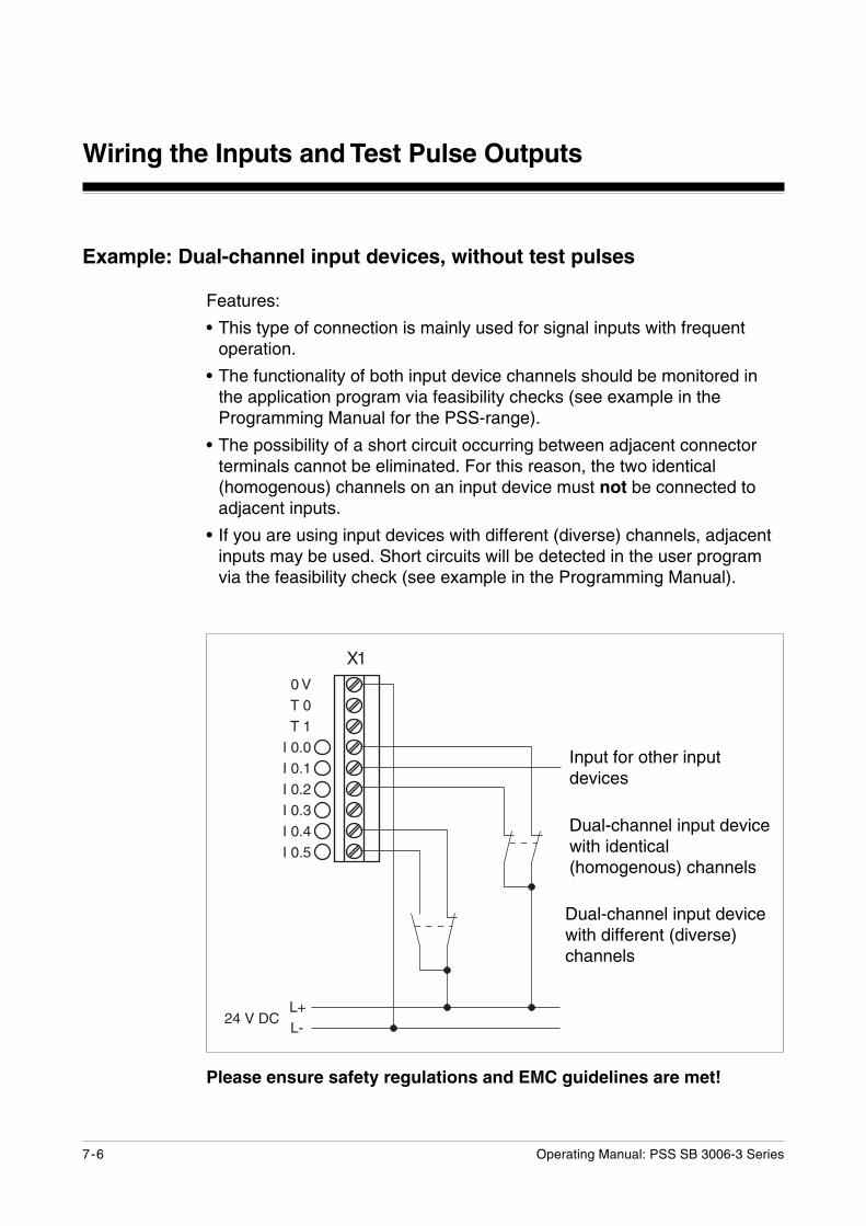
Example: Dual-channel input devices, without test pulses
Features:
• This type of connection is mainly used for signal inputs with frequentoperation.
• The functionality of both input device channels should be monitored inthe application program via feasibility checks (see example in theProgramming Manual for the PSS-range).
• The possibility of a short circuit occurring between adjacent connectorterminals cannot be eliminated. For this reason, the two identical(homogenous) channels on an input device must not be connected toadjacent inputs.
• If you are using input devices with different (diverse) channels, adjacentinputs may be used. Short circuits will be detected in the user programvia the feasibility check (see example in the Programming Manual).
������$� ��
������������������������������������������������
��
Dual-channel input devicewith identical(homogenous) channels
Dual-channel input devicewith different (diverse)channels
Input for other inputdevices
Operating Manual: PSS SB 3006-3 Series 7-7
������$� ��
������������������������������������������������
��
Please ensure safety regulations and EMC guidelines are met!
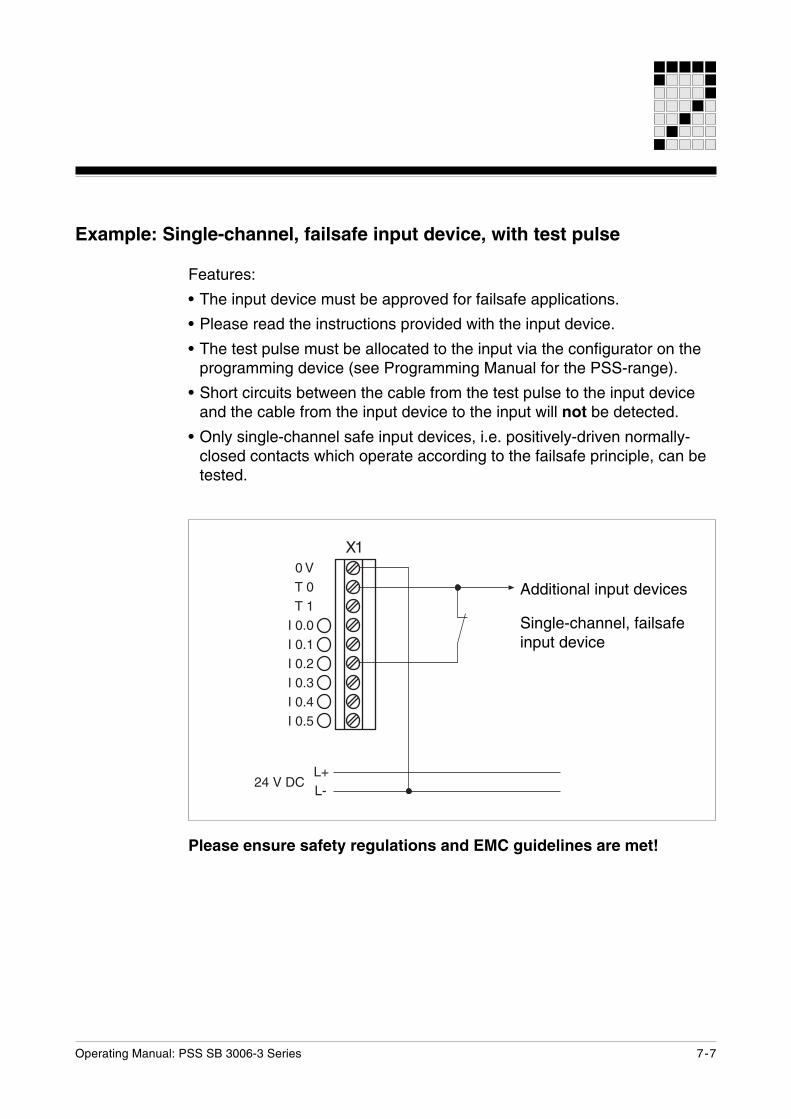
Example: Single-channel, failsafe input device, with test pulse
Features:
• The input device must be approved for failsafe applications.
• Please read the instructions provided with the input device.
• The test pulse must be allocated to the input via the configurator on theprogramming device (see Programming Manual for the PSS-range).
• Short circuits between the cable from the test pulse to the input deviceand the cable from the input device to the input will not be detected.
• Only single-channel safe input devices, i.e. positively-driven normally-closed contacts which operate according to the failsafe principle, can betested.
Additional input devices
Single-channel, failsafeinput device
Wiring the Inputs and Test Pulse Outputs
7-8 Operating Manual: PSS SB 3006-3 Series
������$� ��
������������������������������������������������
��
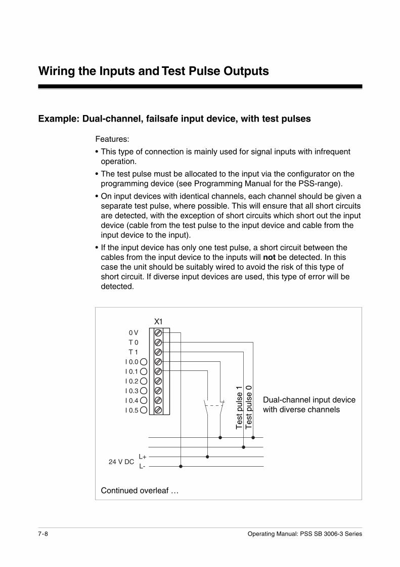
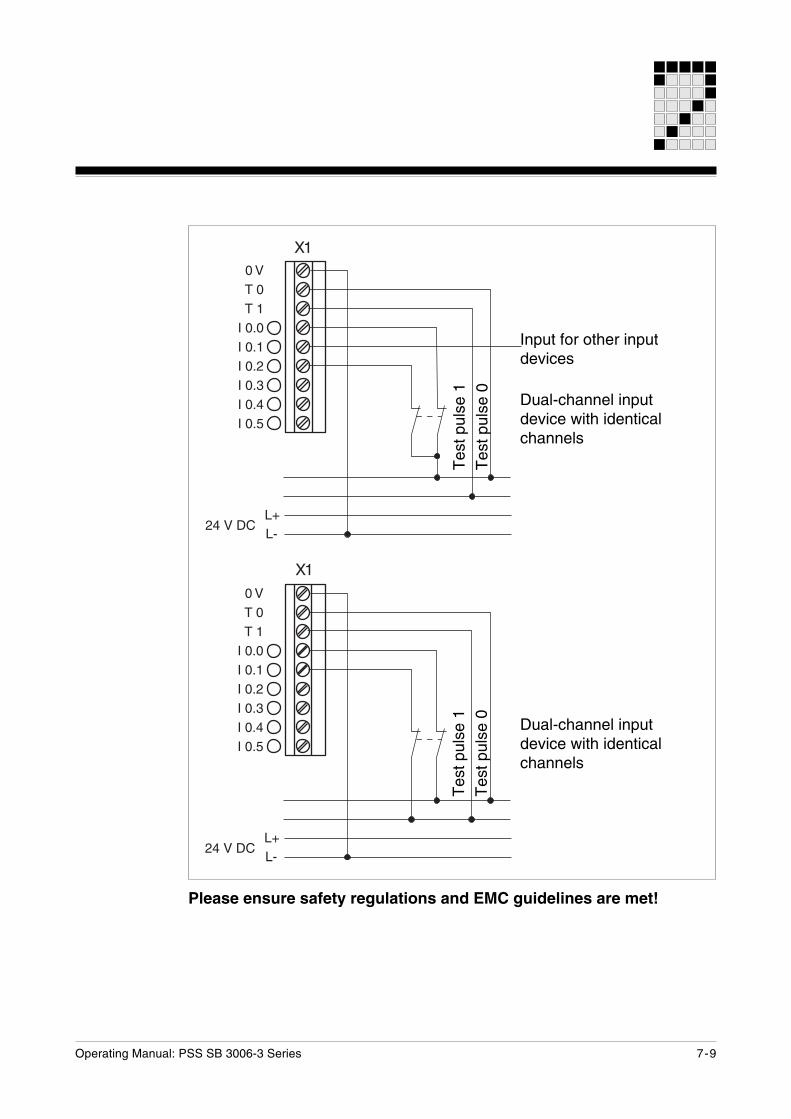
Example: Dual-channel, failsafe input device, with test pulses
Features:
• This type of connection is mainly used for signal inputs with infrequentoperation.
• The test pulse must be allocated to the input via the configurator on theprogramming device (see Programming Manual for the PSS-range).
• On input devices with identical channels, each channel should be given aseparate test pulse, where possible. This will ensure that all short circuitsare detected, with the exception of short circuits which short out the inputdevice (cable from the test pulse to the input device and cable from theinput device to the input).
• If the input device has only one test pulse, a short circuit between thecables from the input device to the inputs will not be detected. In thiscase the unit should be suitably wired to avoid the risk of this type ofshort circuit. If diverse input devices are used, this type of error will bedetected.
Tes
t pul
se 0
Tes
t pul
se 1
Dual-channel input devicewith diverse channels
Continued overleaf …
Operating Manual: PSS SB 3006-3 Series 7-9
������$� ��
������������������������������������������������
��
������$� ��
������������������������������������������������
��
Please ensure safety regulations and EMC guidelines are met!
Tes
t pul
se 0
Tes
t pul
se 1
Dual-channel inputdevice with identicalchannels
Dual-channel inputdevice with identicalchannels
Input for other inputdevices
Tes
t pul
se 0
Tes
t pul
se 1
Wiring the Inputs and Test Pulse Outputs
7-10 Operating Manual: PSS SB 3006-3 Series
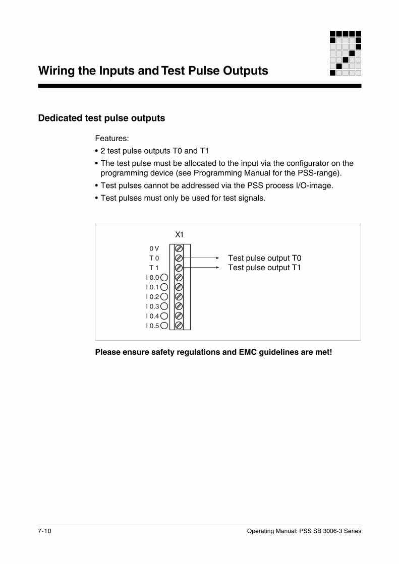
Dedicated test pulse outputs
Features:
• 2 test pulse outputs T0 and T1
• The test pulse must be allocated to the input via the configurator on theprogramming device (see Programming Manual for the PSS-range).
• Test pulses cannot be addressed via the PSS process I/O-image.
• Test pulses must only be used for test signals.
Please ensure safety regulations and EMC guidelines are met!
Test pulse output T1Test pulse output T0
������������������������������������������������
��
Operating Manual: PSS SB 3006-3 Series 8-1
General requirements
We recommend you use screened cable for the RS 232/RS 485 interfaces.If unscreened cables are used, the interfaces may malfunction.
• Earth the cable screening on both sides (e.g. on a bus bar).
• If you are using longer cables and there is the possibility of transientcurrents, you can prevent these by using equipotential bonding cables.If you are unable to use equipotential bonding cables, connect thescreening at one end.
Interfaces
Interfaces
8-2 Operating Manual: PSS SB 3006-3 Series
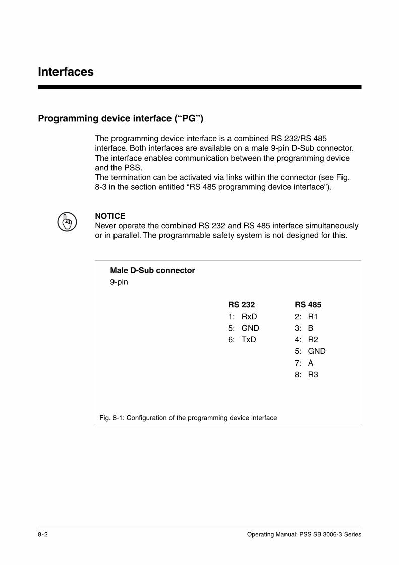
Programming device interface (“PG”)
The programming device interface is a combined RS 232/RS 485interface. Both interfaces are available on a male 9-pin D-Sub connector.The interface enables communication between the programming deviceand the PSS.The termination can be activated via links within the connector (see Fig.8-3 in the section entitled “RS 485 programming device interface”).
NOTICENever operate the combined RS 232 and RS 485 interface simultaneouslyor in parallel. The programmable safety system is not designed for this.
Fig. 8-1: Configuration of the programming device interface
RS 2321: RxD5: GND6: TxD
Male D-Sub connector9-pin
RS 4852: R13: B4: R25: GND7: A8: R3
Operating Manual: PSS SB 3006-3 Series 8-3
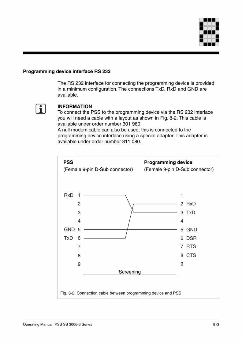
Programming device interface RS 232
The RS 232 interface for connecting the programming device is providedin a minimum configuration. The connections TxD, RxD and GND areavailable.
INFORMATIONTo connect the PSS to the programming device via the RS 232 interfaceyou will need a cable with a layout as shown in Fig. 8-2. This cable isavailable under order number 301 960.A null modem cable can also be used; this is connected to theprogramming device interface using a special adapter. This adapter isavailable under order number 311 080.
�!� �
�
�
�
��� �
�!� �
"
#
�
�
� �!�
� �!�
� ���
� ���
" ���
# $��
�
�
Fig. 8-2: Connection cable between programming device and PSS
PSS(Female 9-pin D-Sub connector)
Programming device(Female 9-pin D-Sub connector)
Screening
Interfaces
8-4 Operating Manual: PSS SB 3006-3 Series
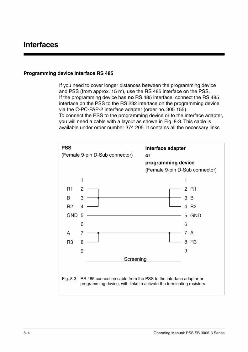
Programming device interface RS 485
If you need to cover longer distances between the programming deviceand PSS (from approx. 15 m), use the RS 485 interface on the PSS.If the programming device has no RS 485 interface, connect the RS 485interface on the PSS to the RS 232 interface on the programming devicevia the C-PC-PAP-2 interface adapter (order no. 305 155).To connect the PSS to the programming device or to the interface adapter,you will need a cable with a layout as shown in Fig. 8-3. This cable isavailable under order number 374 205. It contains all the necessary links.
Fig. 8-3: RS 485 connection cable from the PSS to the interface adapter orprogramming device, with links to activate the terminating resistors
PSS(Female 9-pin D-Sub connector)
Interface adapterorprogramming device(Female 9-pin D-Sub connector)
�
�� �
� �
�� �
��� �
�
"
�� #
�
�
� ��
� �
� ���
�
"
# ��
�
� ��
Screening
Operating Manual: PSS SB 3006-3 Series 8-5
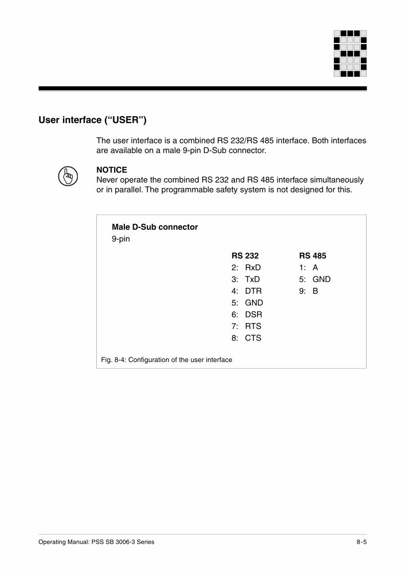
User interface (“USER”)
The user interface is a combined RS 232/RS 485 interface. Both interfacesare available on a male 9-pin D-Sub connector.
NOTICENever operate the combined RS 232 and RS 485 interface simultaneouslyor in parallel. The programmable safety system is not designed for this.
Fig. 8-4: Configuration of the user interface
Male D-Sub connector9-pin
RS 2322: RxD3: TxD4: DTR5: GND6: DSR7: RTS8: CTS
RS 4851: A5: GND9: B
Interfaces
8-6 Operating Manual: PSS SB 3006-3 Series
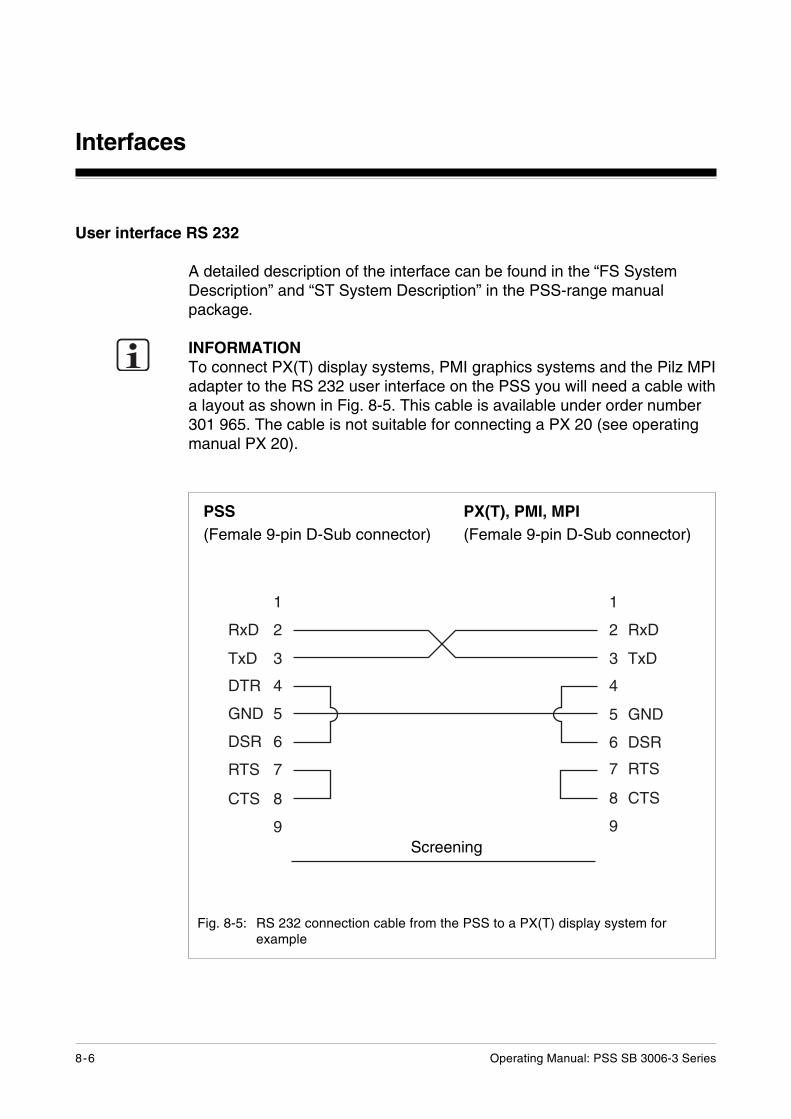
User interface RS 232
A detailed description of the interface can be found in the “FS SystemDescription” and “ST System Description” in the PSS-range manualpackage.
INFORMATIONTo connect PX(T) display systems, PMI graphics systems and the Pilz MPIadapter to the RS 232 user interface on the PSS you will need a cable witha layout as shown in Fig. 8-5. This cable is available under order number301 965. The cable is not suitable for connecting a PX 20 (see operatingmanual PX 20).
Fig. 8-5: RS 232 connection cable from the PSS to a PX(T) display system forexample
PSS(Female 9-pin D-Sub connector)
PX(T), PMI, MPI(Female 9-pin D-Sub connector)
�
�!� �
�!� �
��� �
��� �
��� �
��� "
$�� #
�
�
� �!�
� �!�
� ���
� ���
" ���
# $��
�
�
Screening
Operating Manual: PSS SB 3006-3 Series 8-7
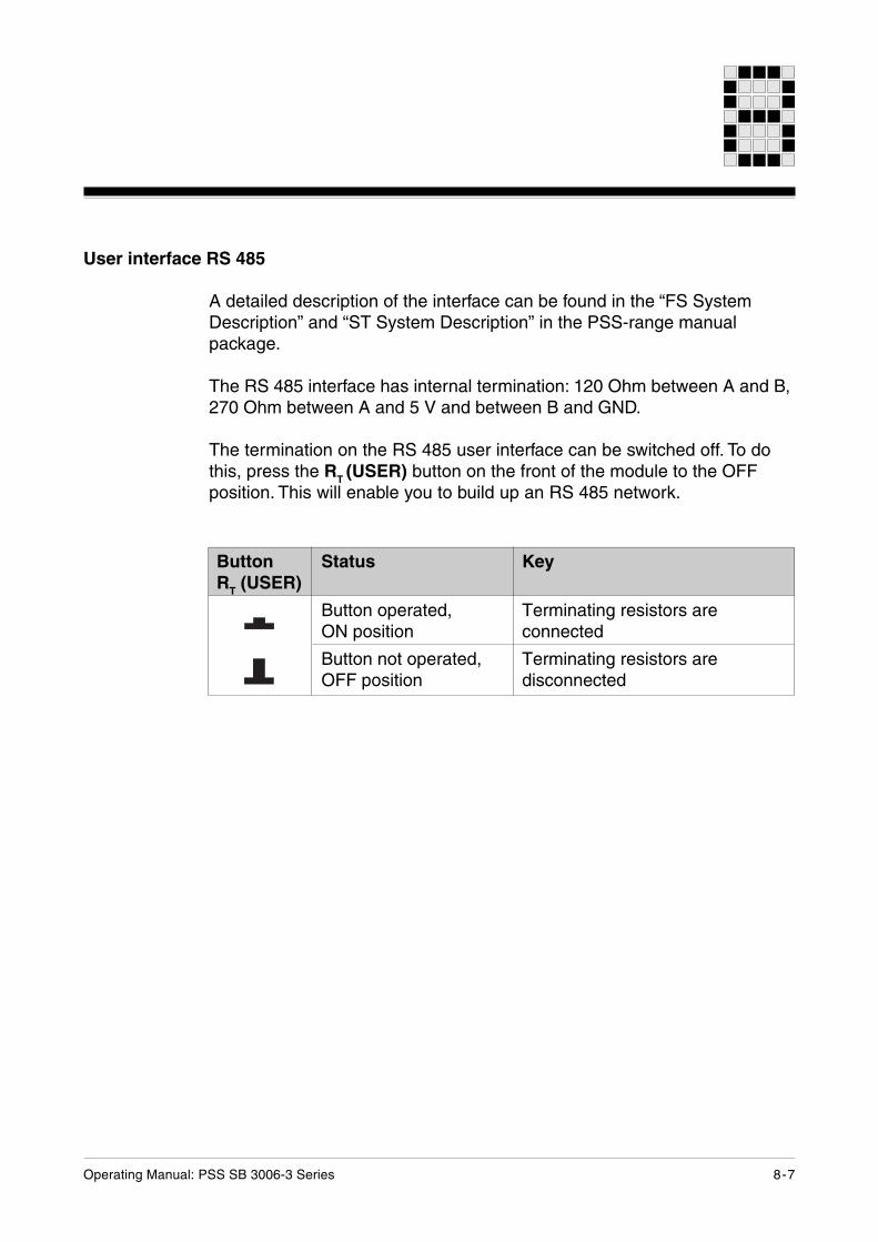
User interface RS 485
A detailed description of the interface can be found in the “FS SystemDescription” and “ST System Description” in the PSS-range manualpackage.
The RS 485 interface has internal termination: 120 Ohm between A and B,270 Ohm between A and 5 V and between B and GND.
The termination on the RS 485 user interface can be switched off. To dothis, press the RT (USER) button on the front of the module to the OFFposition. This will enable you to build up an RS 485 network.
ButtonRT (USER)
Status
Button operated,ON position
Button not operated,OFF position
Key
Terminating resistors areconnected
Terminating resistors aredisconnected
Interfaces
8-8 Operating Manual: PSS SB 3006-3 Series
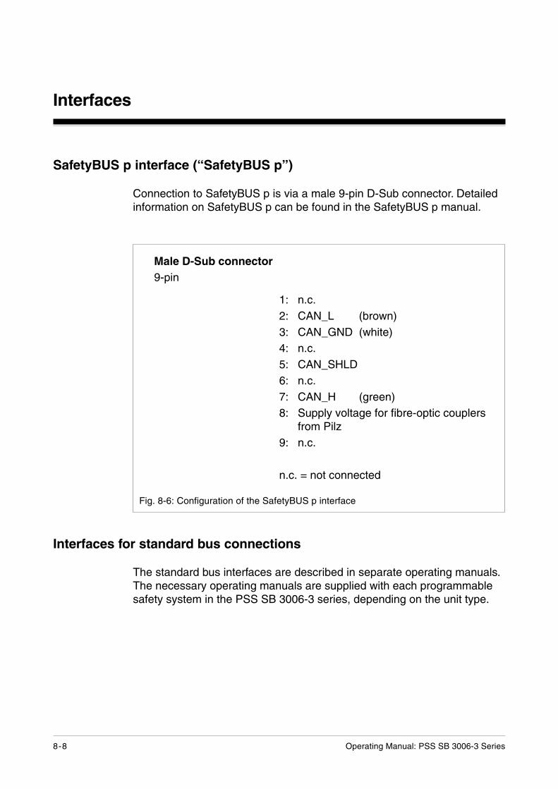
Fig. 8-6: Configuration of the SafetyBUS p interface
1: n.c.2: CAN_L (brown)3: CAN_GND (white)4: n.c.5: CAN_SHLD6: n.c.7: CAN_H (green)8: Supply voltage for fibre-optic couplers
from Pilz9: n.c.
n.c. = not connected
Male D-Sub connector9-pin
SafetyBUS p interface (“SafetyBUS p”)
Connection to SafetyBUS p is via a male 9-pin D-Sub connector. Detailedinformation on SafetyBUS p can be found in the SafetyBUS p manual.
Interfaces for standard bus connections
The standard bus interfaces are described in separate operating manuals.The necessary operating manuals are supplied with each programmablesafety system in the PSS SB 3006-3 series, depending on the unit type.
Operating Manual: PSS SB 3006-3 Series 9-1
Operation and Maintenance
Commissioning
• Install the programmable safety system as described in Chapter 5,“Installation”.
• Connect the inputs and test pulse outputs as described in Chapter 7,“Wiring the Inputs and Test Pulse Outputs”.
• Supply voltage for the PSS - as described in Chapter 6 “Supply Voltage”- connect and switch on.
Faults
PSS and SafetyBUS p functionalityIf a fault occurs on the safety system or there is a wiring error, the PSS willswitch to a STOP condition and output a message to the display. All thedecentralised outputs in the I/O-Groups that are assigned to the LD on thePSS will also be switched off.The error stack display in the system software (e.g. PSS-WIN-PRO) canbe used to locate the error. The description for error evaluation can befound in the “FS System Description” in the PSS-range manual package.
Standard bus functionalityVarious options are available, should a standard bus interface not achievethe correct operating status:
• Evaluation of the relevant LEDs for operating status(see operating manual for the relevant standard bus system)
• The drivers (standard function blocks) of the standard bus systems willprovide some diagnostic options (see operating manual for the relevantsoftware package).
• Bus diagnostics via a corresponding network analyzerNetwork analyzers from various companies are available for the differentbus systems. Further information can be found in the operating manualfor the relevant analyzer.
Operation and Maintenance
9-2 Operating Manual: PSS SB 3006-3 Series
Display elements
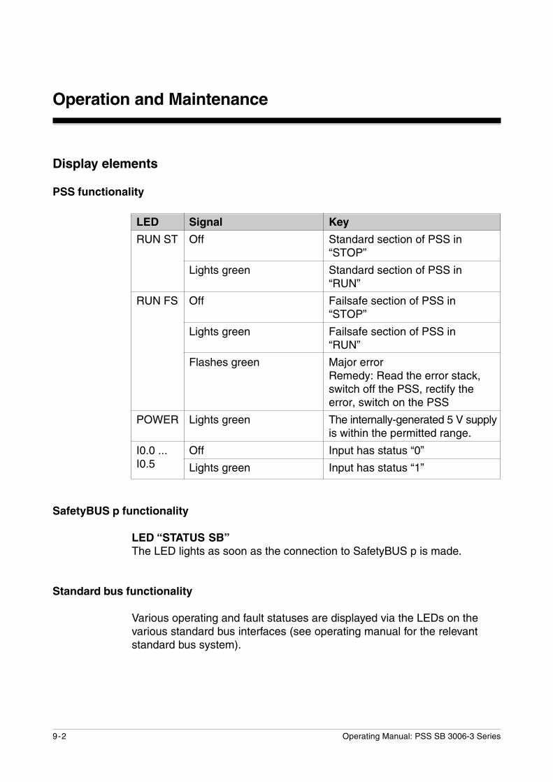
PSS functionality
LED
RUN ST
RUN FS
POWER
I0.0 ...I0.5
Signal
Off
Lights green
Off
Lights green
Flashes green
Lights green
Off
Lights green
Key
Standard section of PSS in“STOP”
Standard section of PSS in“RUN”
Failsafe section of PSS in“STOP”
Failsafe section of PSS in“RUN”
Major errorRemedy: Read the error stack,switch off the PSS, rectify theerror, switch on the PSS
The internally-generated 5 V supplyis within the permitted range.
Input has status “0”
Input has status “1”
SafetyBUS p functionality
LED “STATUS SB”The LED lights as soon as the connection to SafetyBUS p is made.
Standard bus functionality
Various operating and fault statuses are displayed via the LEDs on thevarious standard bus interfaces (see operating manual for the relevantstandard bus system).
Operating Manual: PSS SB 3006-3 Series 9-3
Changing the battery
If the battery voltage drops below 2.5 V, the CPU will issue the errormessage “S-04”. You should then change the battery, Only use a batterytype that has been approved by Pilz (see chapter entitled “TechnicalDetails”). Battery types that are approved by Pilz are “UL-Recognized”.
CAUTION!
• Damage due to electrostatic discharge!Electrostatic discharge can damage components on the safety system.Ensure against discharge before touching the PSS, e.g. by touching anearthed, conductive surface or by wearing an earthed armband.
• Data loss!The battery should be changed when the supply voltage is switched off.The CPU will retain data for approx. 2 minutes. If it takes longer tochange the battery, data will be lost.
WARNING!
Risk of injury due to improper handling or due to damaged lithiumbatteries!Lithium batteries may only be exchanged by specialist staff who have beentrained to deal with lithium batteries.
Dead batteries must be disposed of properly!
Operation and Maintenance
9-4 Operating Manual: PSS SB 3006-3 Series
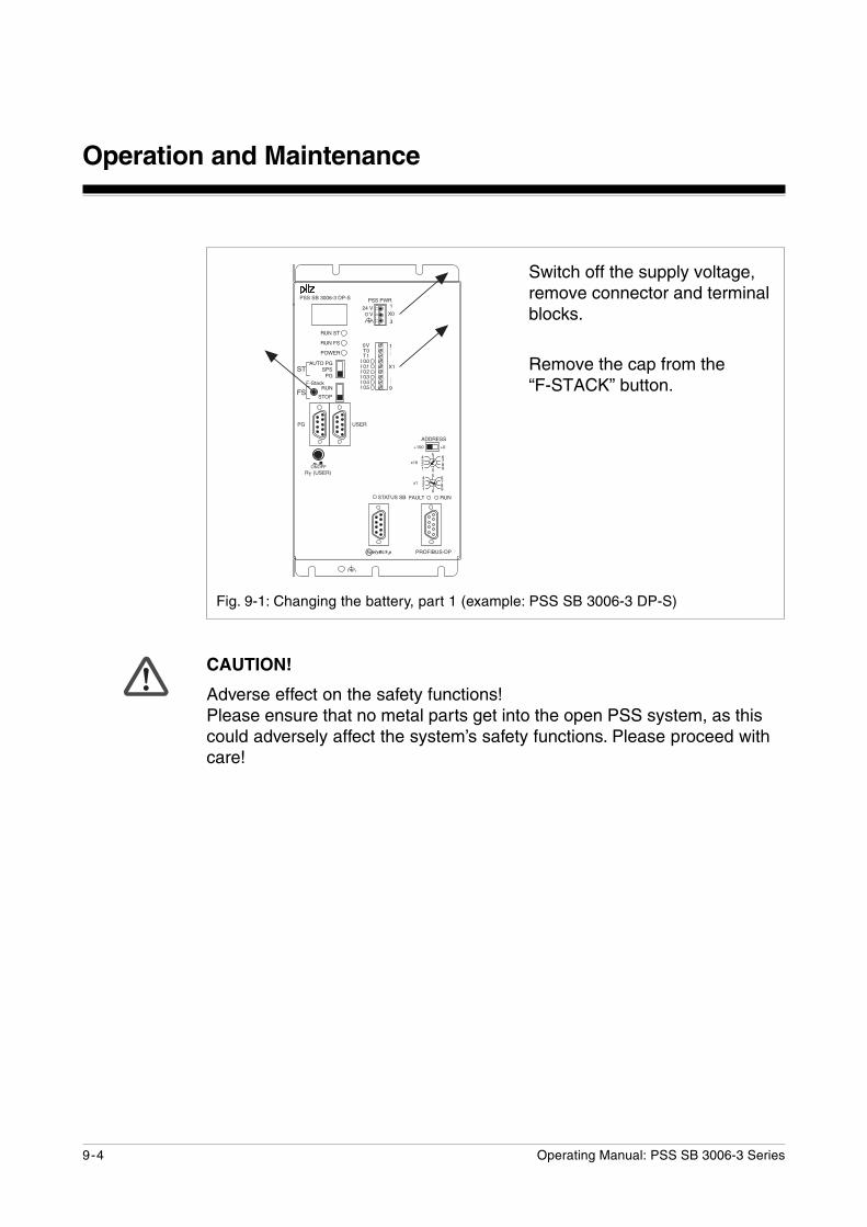
Fig. 9-1: Changing the battery, part 1 (example: PSS SB 3006-3 DP-S)
������
������
���
��
����������
��
��� �
!�
���� ���
���
���
����������
������
������������������������������������������������
��
����
����
!���"#�
����
�
�
�"#�
����
�
�
������
������������������
������������
������
�� ����
��
���� � �
����
�������
CAUTION!
Adverse effect on the safety functions!Please ensure that no metal parts get into the open PSS system, as thiscould adversely affect the system’s safety functions. Please proceed withcare!
Switch off the supply voltage,remove connector and terminalblocks.
Remove the cap from the“F-STACK” button.
Operating Manual: PSS SB 3006-3 Series 9-5
������
������
���
��
����������
��
��� �
!�
���� ���
���
���
����������
������
������������������������������������������������
��
����
����
!���"#�
����
�
�
�"#�
����
�
�
������
������������������
������������
������
�� ����
��
���� � �
����
�������
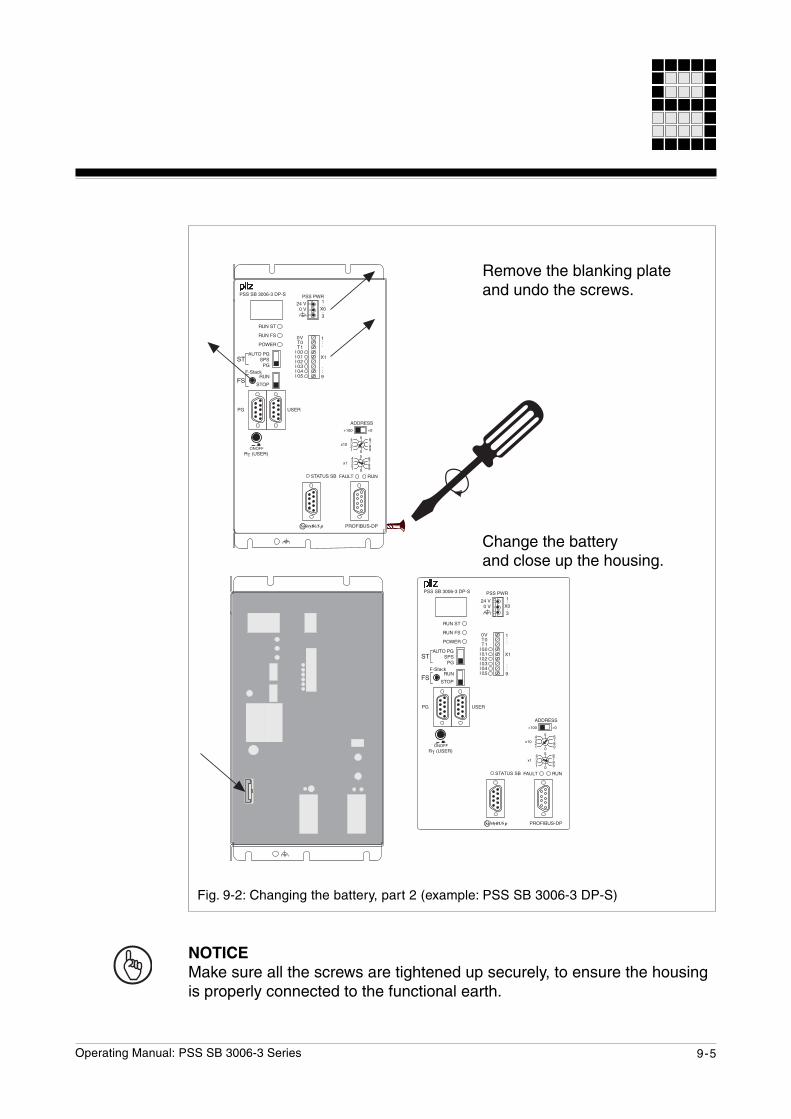
Fig. 9-2: Changing the battery, part 2 (example: PSS SB 3006-3 DP-S)
������
������
���
��
����������
��
��� �
!�
���� ���
���
���
����������
������
������������������������������������������������
��
����
����
!���"#�
����
�
�
�"#�
����
�
�
������
������������������
������������
������
�� ����
��
���� � �
����
�������
Remove the blanking plateand undo the screws.
Change the batteryand close up the housing.
NOTICEMake sure all the screws are tightened up securely, to ensure the housingis properly connected to the functional earth.
Operation and Maintenance
9-6 Operating Manual: PSS SB 3006-3 Series
Notes
10-1Operating Manual: PSS SB 3006-3 Series
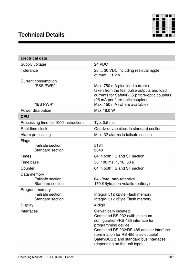
Technical Details
Electrical data
Supply voltage
Tolerance
Current consumption“PSS PWR”
“IBS PWR”
Power dissipation
CPU
Processing time for 1000 instructions
Real-time clock
Alarm processing
FlagsFailsafe sectionStandard section
Times
Time base
Counter
Data memoryFailsafe sectionStandard section
Program memoryFailsafe sectionStandard section
Display
Interfaces
24 VDC
20 ... 30 VDC including residual rippleof max. ± 1.2 V
Max. 750 mA plus load currentstaken from the test pulse outputs and loadcurrents for SafetyBUS p fibre-optic couplers(25 mA per fibre-optic coupler)Max. 150 mA (where available)
Max 18.0 W
Typ. 0.5 ms
Quartz-driven clock in standard section
Max. 32 alarms in failsafe section
51842048
64 in both FS and ST section
50, 100 ms; 1, 10, 60 s
64 in both FS and ST section
64 kByte, non-retentive170 KByte, non-volatile (battery)
Integral 512 kByte Flash memoryIntegral 512 kByte Flash memory
4-digit
Galvanically isolated:Combined RS 232 (with minimumconfiguration)/RS 485 interface forprogramming device,Combined RS 232/RS 485 as user interface(termination for RS 485 is selectable)SafetyBUS p and standard bus interfaces(depending on the unit type)
Technical Details
10-2 Operating Manual: PSS SB 3006-3 Series
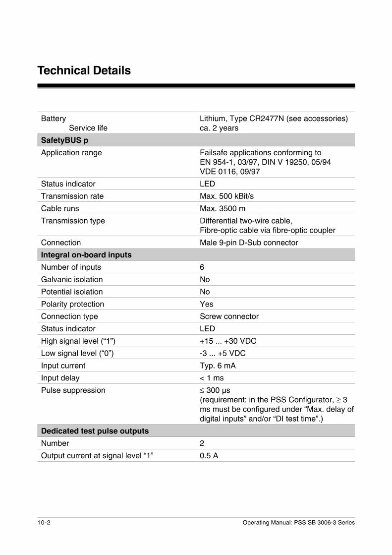
BatteryService life
SafetyBUS p
Application range
Status indicator
Transmission rate
Cable runs
Transmission type
Connection
Integral on-board inputs
Number of inputs
Galvanic isolation
Potential isolation
Polarity protection
Connection type
Status indicator
High signal level (“1”)
Low signal level (“0”)
Input current
Input delay
Pulse suppression
Dedicated test pulse outputs
Number
Output current at signal level “1”
Lithium, Type CR2477N (see accessories)ca. 2 years
Failsafe applications conforming toEN 954-1, 03/97, DIN V 19250, 05/94VDE 0116, 09/97
LED
Max. 500 kBit/s
Max. 3500 m
Differential two-wire cable,Fibre-optic cable via fibre-optic coupler
Male 9-pin D-Sub connector
6
No
No
Yes
Screw connector
LED
+15 ... +30 VDC
-3 ... +5 VDC
Typ. 6 mA
< 1 ms
≤ 300 µs(requirement: in the PSS Configurator, ≥ 3ms must be configured under “Max. delay ofdigital inputs” and/or “DI test time”.)
2
0.5 A
10-3Operating Manual: PSS SB 3006-3 Series
The names of products, goods and technologies used in this manual are trademarks of the respective companies.
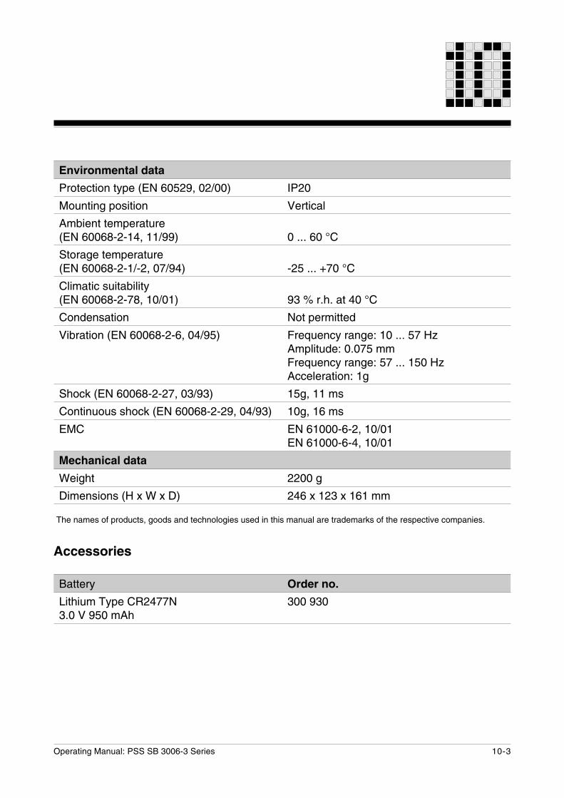
Environmental data
Protection type (EN 60529, 02/00)
Mounting position
Ambient temperature(EN 60068-2-14, 11/99)
Storage temperature(EN 60068-2-1/-2, 07/94)
Climatic suitability(EN 60068-2-78, 10/01)
Condensation
Vibration (EN 60068-2-6, 04/95)
Shock (EN 60068-2-27, 03/93)
Continuous shock (EN 60068-2-29, 04/93)
EMC
Mechanical data
Weight
Dimensions (H x W x D)
IP20
Vertical
0 ... 60 °C
-25 ... +70 °C
93 % r.h. at 40 °C
Not permitted
Frequency range: 10 ... 57 HzAmplitude: 0.075 mmFrequency range: 57 ... 150 HzAcceleration: 1g
15g, 11 ms
10g, 16 ms
EN 61000-6-2, 10/01EN 61000-6-4, 10/01
2200 g
246 x 123 x 161 mm
Accessories
Battery
Lithium Type CR2477N3.0 V 950 mAh
Order no.
300 930
Technical Details
10-4 Operating Manual: PSS SB 3006-3 Series
Notes
11-1Operating Manual: PSS SB 3006-3 Series
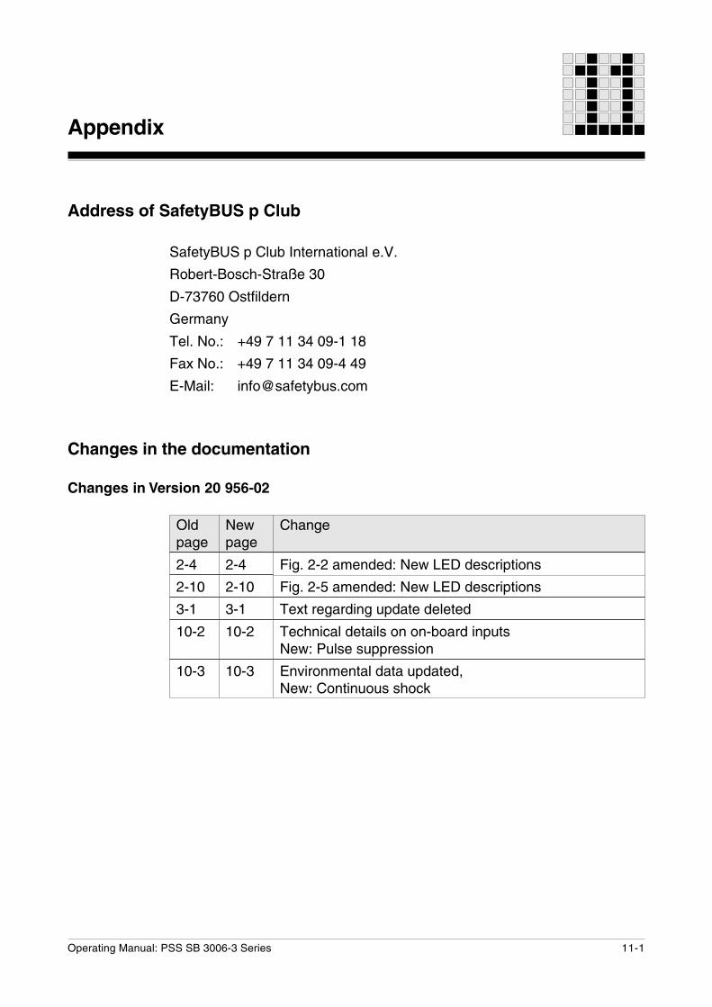
Address of SafetyBUS p Club
SafetyBUS p Club International e.V.
Robert-Bosch-Straße 30
D-73760 Ostfildern
Germany
Tel. No.: +49 7 11 34 09-1 18
Fax No.: +49 7 11 34 09-4 49
E-Mail: [email protected]
Changes in the documentation
Changes in Version 20 956-02
Oldpage
2-4
2-10
3-1
10-2
10-3
Newpage
2-4
2-10
3-1
10-2
10-3
Change
Fig. 2-2 amended: New LED descriptions
Fig. 2-5 amended: New LED descriptions
Text regarding update deleted
Technical details on on-board inputsNew: Pulse suppression
Environmental data updated,New: Continuous shock
Appendix
Appendix
11-2 Operating Manual: PSS SB 3006-3 Series
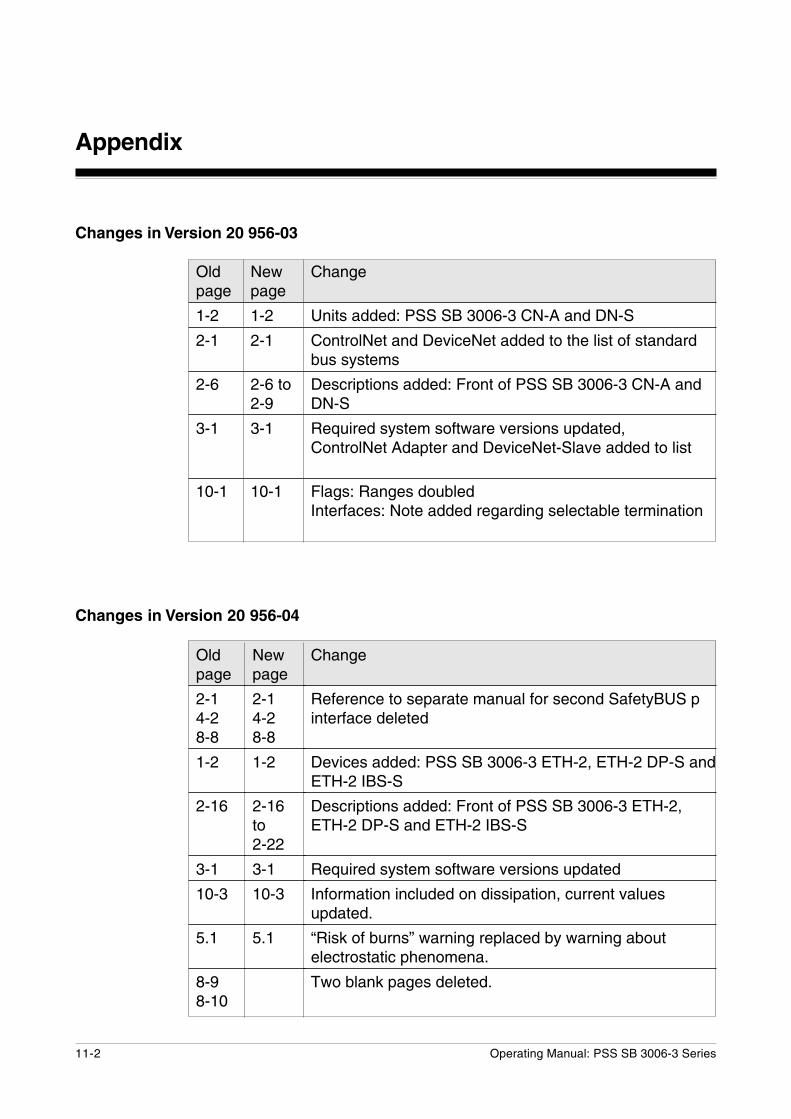
Changes in Version 20 956-03
Changes in Version 20 956-04
Oldpage
2-14-28-8
1-2
2-16
3-1
10-3
5.1
8-98-10
Newpage
2-14-28-8
1-2
2-16to2-22
3-1
10-3
5.1
Change
Reference to separate manual for second SafetyBUS pinterface deleted
Devices added: PSS SB 3006-3 ETH-2, ETH-2 DP-S andETH-2 IBS-S
Descriptions added: Front of PSS SB 3006-3 ETH-2,ETH-2 DP-S and ETH-2 IBS-S
Required system software versions updated
Information included on dissipation, current valuesupdated.
“Risk of burns” warning replaced by warning aboutelectrostatic phenomena.
Two blank pages deleted.
Oldpage
1-2
2-1
2-6
3-1
10-1
Newpage
1-2
2-1
2-6 to2-9
3-1
10-1
Change
Units added: PSS SB 3006-3 CN-A and DN-S
ControlNet and DeviceNet added to the list of standardbus systems
Descriptions added: Front of PSS SB 3006-3 CN-A andDN-S
Required system software versions updated,ControlNet Adapter and DeviceNet-Slave added to list
Flags: Ranges doubledInterfaces: Note added regarding selectable termination
11-3Operating Manual: PSS SB 3006-3 Series
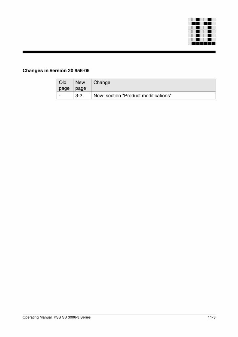
Changes in Version 20 956-05
Oldpage
-
Newpage
3-2
Change
New: section "Product modifications"
Appendix
11-4 Operating Manual: PSS SB 3006-3 Series
Notes

... wwwwww.pilz.com
+49 711 3409-444
Pilz GmbH & Co. KGSichere AutomationFelix-Wankel-Straße 273760 Ostfildern, GermanyTelephone: +49 711 3409-0Telefax: +49 711 3409-133E-Mail: [email protected]
In many countries we arerepresented by our subsidiariesand sales partners.
Please refer to our Homepagefor further details or contact ourheadquarters.
Technical support
20 9
56-0
5, 2
006-
05 P
rint
ed in
Ger
man
y