Pspug.book Page 321 Tuesday, November 2, 1999 2:29 …fontana/spiceman/AC_Analysis.pdf · AC...
18
AC analyses 10 Chapter overview This chapter describes how to set up AC sweep and noise analyses. • AC sweep analysis on page 322 describes how to set up an analysis to calculate the frequency response of your circuit. This section also discusses how to define an AC stimulus and how PSpice A/D treats nonlinear devices in an AC sweep. • Noise analysis on page 331 describes how to set up an analysis to calculate device noise contributions and total input and output noise.
Transcript of Pspug.book Page 321 Tuesday, November 2, 1999 2:29 …fontana/spiceman/AC_Analysis.pdf · AC...

AC analyses
10
Chapter overviewThis chapter describes how to set up AC sweep and noise analyses.
• AC sweep analysis on page 322 describes how to set up an analysis to calculate the frequency response of your circuit. This section also discusses how to define an AC stimulus and how PSpice A/D treats nonlinear devices in an AC sweep.
• Noise analysis on page 331 describes how to set up an analysis to calculate device noise contributions and total input and output noise.
Pspug.book Page 321 Tuesday, November 2, 1999 2:29 PM
Chapter 10 AC analyses
322
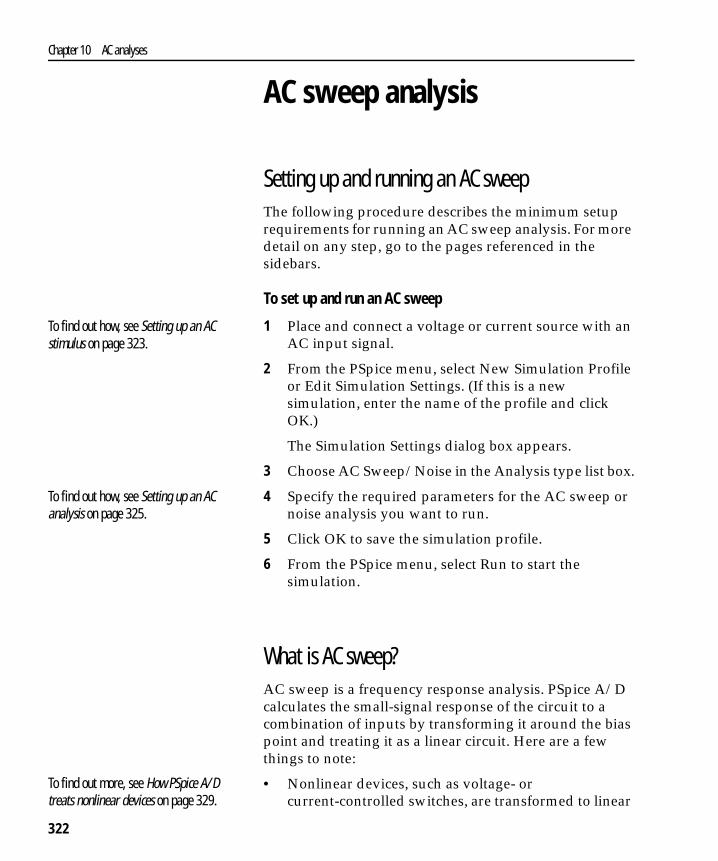
AC sweep analysis
Setting up and running an AC sweepThe following procedure describes the minimum setup requirements for running an AC sweep analysis. For more detail on any step, go to the pages referenced in the sidebars.
To set up and run an AC sweep
1 Place and connect a voltage or current source with an AC input signal.
2 From the PSpice menu, select New Simulation Profile or Edit Simulation Settings. (If this is a new simulation, enter the name of the profile and click OK.)
The Simulation Settings dialog box appears.
3 Choose AC Sweep/Noise in the Analysis type list box.
4 Specify the required parameters for the AC sweep or noise analysis you want to run.
5 Click OK to save the simulation profile.
6 From the PSpice menu, select Run to start the simulation.
What is AC sweep?AC sweep is a frequency response analysis. PSpice A/D calculates the small-signal response of the circuit to a combination of inputs by transforming it around the bias point and treating it as a linear circuit. Here are a few things to note:
• Nonlinear devices, such as voltage- or current-controlled switches, are transformed to linear
To find out how, see Setting up an AC stimulus on page 323.
To find out how, see Setting up an AC analysis on page 325.
To find out more, see How PSpice A/D treats nonlinear devices on page 329.
Pspug.book Page 322 Tuesday, November 2, 1999 2:29 PM

AC sweep analysis
323
circuits about their bias point value before PSpice A/D runs the linear (small-signal) analysis.
• Digital devices hold the states that PSpice A/D calculated when solving for the bias point.
• Because AC sweep analysis is a linear analysis, it only considers the gain and phase response of the circuit; it does not limit voltages or currents.
The best way to use AC sweep analysis is to set the source magnitude to one. This way, the measured output equals the gain, relative to the input source, at that output.
Setting up an AC stimulusTo run an AC sweep analysis, you need to place and connect one or more independent sources and then set the AC magnitude and phase for each source.
To set up an AC stimulus
1 Place and connect one of these symbols in your schematic:
For voltage input
Use this... When you are running...
VAC An AC sweep analysis only.
VSRC Multiple analysis types including AC sweep.
For current input
Use this... When you are running...
IAC An AC sweep analysis only.
ISRC Multiple analysis types including AC sweep.
Note Unlike DC sweep, the AC Sweep/Noise dialog box not include an input source option. Instead, each independent source in your circuit contains its own AC specification for magnitude and phase.
If you are planning to run a DC or transient analysis in addition to an AC analysis, see If you want to specify multiple stimulus types on page 113 for additional information and source symbols that you can use.
Pspug.book Page 323 Tuesday, November 2, 1999 2:29 PM

Chapter 10 AC analyses
324
2 Double-click the symbol instance to display the Parts spreadsheet.
3 Click in the cell under the appropriate property column to edit its value. Depending on the source symbol that you placed, define the AC specification as follows:
For VAC or IAC
Set this property... To this value...
ACMAG AC magnitude in volts (for VAC) or amps (for IAC); units are optional.
ACPHASE Optional AC phase in degrees.
For VSRC or ISRC
Set this property... To this value...
AC Magnitude_value [phase_value]where magnitude_value is in volts or amps (units are optional) and the optional phase_value is in degrees.
If you are also planning to run a transient analysis, see Using VSRC or ISRC parts on page 114 to find out how to specify the TRAN property.
Pspug.book Page 324 Tuesday, November 2, 1999 2:29 PM

AC sweep analysis
325
Setting up an AC analysis
To set up the AC analysis
1 From the PSpice menu, choose New Simulation Profile or Edit Simulation Settings. (If this is a new simulation, enter the name of the profile and click OK.)
The Simulation Settings dialog box appears.
2 Choose AC Sweep/Noise in the Analysis type list box.
3 Under Options, select General Settings if it is not already enabled.
4 Set the number of sweep points as follows:
Pspug.book Page 325 Tuesday, November 2, 1999 2:29 PM
Chapter 10 AC analyses
326
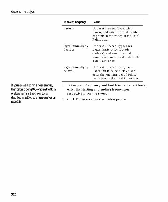
5 In the Start Frequency and End Frequency text boxes, enter the starting and ending frequencies, respectively, for the sweep.
6 Click OK to save the simulation profile.
To sweep frequency... Do this...
linearly Under AC Sweep Type, click Linear, and enter the total number of points in the sweep in the Total Points box.
logarithmically by decades
Under AC Sweep Type, click Logarithmic, select Decade (default), and enter the total number of points per decade in the Total Points box.
logarithmically by octaves
Under AC Sweep Type, click Logarithmic, select Octave, and enter the total number of points per octave in the Total Points box.
If you also want to run a noise analysis, then before clicking OK, complete the Noise Analysis frame in this dialog box as described in Setting up a noise analysis on page 333.
Pspug.book Page 326 Tuesday, November 2, 1999 2:29 PM
AC sweep analysis
327
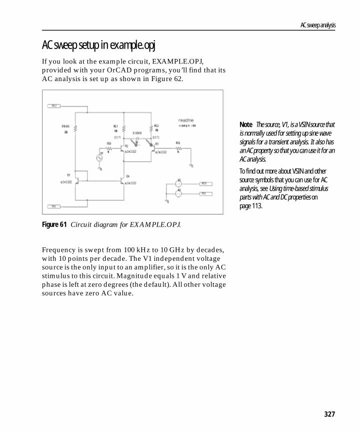
AC sweep setup in example.opjIf you look at the example circuit, EXAMPLE.OPJ, provided with your OrCAD programs, you’ll find that its AC analysis is set up as shown in Figure 62.
Figure 61 Circuit diagram for EXAMPLE.OPJ.
Frequency is swept from 100 kHz to 10 GHz by decades, with 10 points per decade. The V1 independent voltage source is the only input to an amplifier, so it is the only AC stimulus to this circuit. Magnitude equals 1 V and relative phase is left at zero degrees (the default). All other voltage sources have zero AC value.
Note The source, V1, is a VSIN source that is normally used for setting up sine wave signals for a transient analysis. It also has an AC property so that you can use it for an AC analysis.
To find out more about VSIN and other source symbols that you can use for AC analysis, see Using time-based stimulus parts with AC and DC properties on page 113.
Pspug.book Page 327 Tuesday, November 2, 1999 2:29 PM
Chapter 10 AC analyses
328
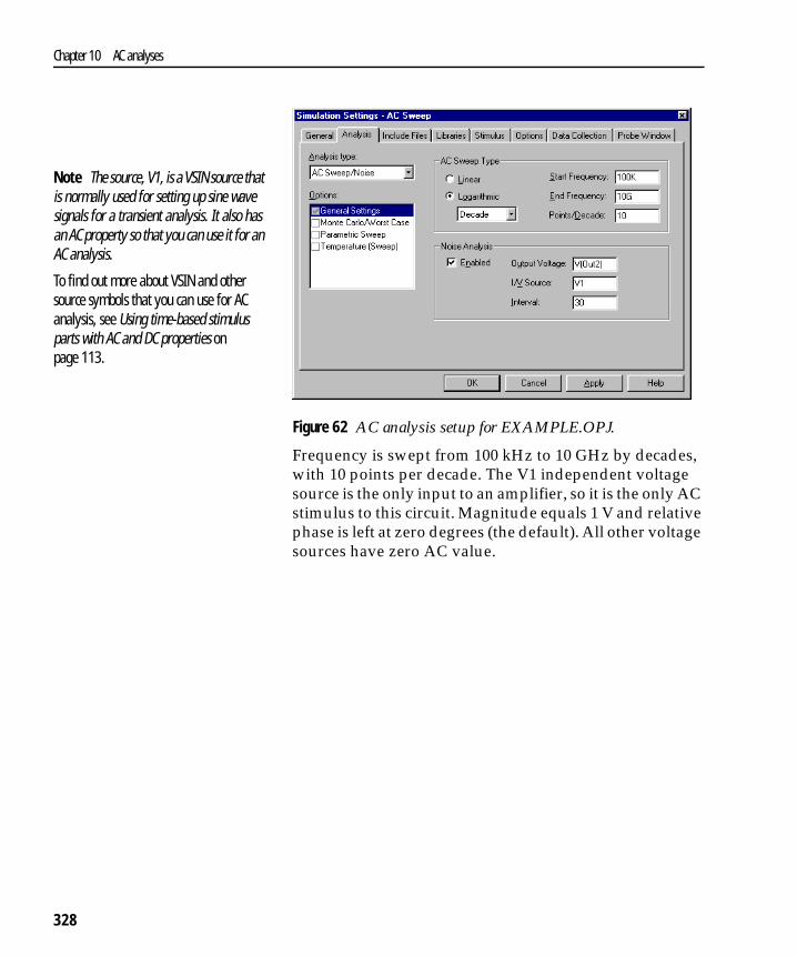
Figure 62 AC analysis setup for EXAMPLE.OPJ.
Frequency is swept from 100 kHz to 10 GHz by decades, with 10 points per decade. The V1 independent voltage source is the only input to an amplifier, so it is the only AC stimulus to this circuit. Magnitude equals 1 V and relative phase is left at zero degrees (the default). All other voltage sources have zero AC value.
Note The source, V1, is a VSIN source that is normally used for setting up sine wave signals for a transient analysis. It also has an AC property so that you can use it for an AC analysis.
To find out more about VSIN and other source symbols that you can use for AC analysis, see Using time-based stimulus parts with AC and DC properties on page 113.
Pspug.book Page 328 Tuesday, November 2, 1999 2:29 PM
AC sweep analysis
329
How PSpice A/D treats nonlinear devicesAn AC Sweep analysis is a linear or small-signal analysis. This means that nonlinear devices must be linearized to run the analysis.
What’s required to transform a device into a linear circuitIn order to transform a device (such as a transistor amplifier) into a linear circuit, you must do the following:
1 Compute the DC bias point for the circuit.
2 Compute the complex impedance and/or transconductance values for each device at this bias point.
3 Perform the linear circuit analysis at the frequencies of interest by using simplifying approximations.
What PSpice A/D doesPSpice A/D automates this process for you. PSpice A/D computes the partial derivatives for nonlinear devices at the bias point and uses these to perform small-signal analysis.
Example: nonlinear behavioral modeling blockSuppose you have an analog behavioral modeling block that multiplies V(1) by V(2). Multiplication is a nonlinear operation. To run an AC sweep analysis on this block, the block needs to be replaced with its linear equivalent. To determine the linear equivalent block, PSpice A/D needs a known bias point.
Example: Replace a bipolar transistor in common-emitter mode with a constant transconductance (collector current proportional to base-emitter voltage) and a number of constant impedances.
Pspug.book Page 329 Tuesday, November 2, 1999 2:29 PM

Chapter 10 AC analyses
330
Using a DC source
Consider the circuit shown here. At the DC bias point, PSpice A/D calculates the partial derivatives which determine the linear response of the multiplier as follows:
For this circuit, this equation reduces to:
This means that the multiplier acts as an amplifier of the AC input with a gain that is set by the DC input.
Caution: multiplying AC sources
Suppose that you replace the 2 volt DC source in this example with an AC source with amplitude 1 and no DC value (DC=0). When PSpice A/D computes the bias point, there are no DC sources in the circuit, so all nodes are at 0 volts at the bias point. The linear equivalent of the multiplier block is a block with gain 0, which means that there is no output voltage at the fundamental frequency.
V Out( ) V In1( ) V Out( )∂V In1( )∂
---------------------⋅ V In2( ) V Out( )∂V In2( )∂
---------------------⋅+=
V In1( )= V In2( )⋅ V In2( ) V In1( )⋅+
V Out( ) V In1( ) 2 V In2( ) 0⋅+⋅=
This is exactly how a double-balanced mixer behaves. In practice, this is a simple multiplier.
Note A double-balanced mixer with inputs at the same frequency would produce outputs at DC at twice the input frequency, but these terms cannot be seen with a linear, small-signal analysis.
Pspug.book Page 330 Tuesday, November 2, 1999 2:29 PM

Noise analysis
331
Noise analysis
Setting up and running a noise analysisThe following procedure describes the minimum setup requirements for running a noise analysis. For more detail on any step, go to the pages referenced in the sidebars.
To set up and run an AC sweep
1 Place and connect a voltage or current source with an AC input signal.
2 Set up the AC sweep simulation specifications.
3 Set up the noise simulation specifications and enable the analysis in the AC Sweep/Noise portion of the Simulation Settings dialog box.
4 Click OK to save the simulation profile.
5 From the PSpice menu, choose Run to start the simulation.
To find out how, see Setting up an AC stimulus on page 323.
To find out how, see Setting up an AC analysis on page 325.To find out how, see Setting up a noise analysis on page 333.
Pspug.book Page 331 Tuesday, November 2, 1999 2:29 PM
Chapter 10 AC analyses
332
What is noise analysis?When running a noise analysis, PSpice A/D calculates and reports the following for each frequency specified for the AC Sweep/Noise analysis:
• Device noise, which is the noise contribution propagated to the specified output net from every resistor and semiconductor device in the circuit; for semiconductor devices, the device noise is also broken down into constituent noise contributions where applicable
• Total output and equivalent input noise
How PSpice A/D calculates total outputand input noiseTo calculate total noise at an output net, PSpice A/D computes the RMS sum of the noise propagated to the net by all noise-generating devices in the circuit.
To calculate the equivalent input noise, PSpice A/D then divides total output noise by the gain from the input source to the output net. This results in the amount of noise which, if injected at the input source into a noiseless circuit, would produce the total noise originally calculated for the output net.
This value... Means this...
Output noise RMS sum of all the device contributions propagated to a specified output net
Input noise equivalent noise that would be needed at the input source to generate the calculated output noise in an ideal (noiseless) circuit
Example: Diodes have separate noise contributions from thermal, shot, and flicker noise.
Pspug.book Page 332 Tuesday, November 2, 1999 2:29 PM
Noise analysis
333
Setting up a noise analysis
To set up the noise analysis
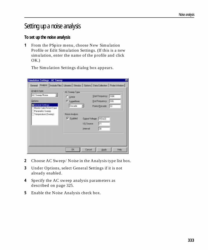
1 From the PSpice menu, choose New Simulation Profile or Edit Simulation Settings. (If this is a new simulation, enter the name of the profile and click OK.)
The Simulation Settings dialog box appears.
2 Choose AC Sweep/Noise in the Analysis type list box.
3 Under Options, select General Settings if it is not already enabled.
4 Specify the AC sweep analysis parameters as described on page 325.
5 Enable the Noise Analysis check box.
Pspug.book Page 333 Tuesday, November 2, 1999 2:29 PM

Chapter 10 AC analyses
334
6 Enter the noise analysis parameters as follows:
7 Click OK to save the simulation profile.
In this text box... Type this...
Output Voltage A voltage output variable of the form V(node, [node]) where you want the total output noise calculated.
I/V Source The name of an independent current or voltage source where you want the equivalent input noise calculated.Note If the source is in a lower level of a hierarchical schematic, separate the names of the hierarchical devices with periods (.).
Interval An integer n designating that at every nth frequency, you want to see a table printed in the PSpice output file (.out) showing the individual contributions of all of the circuit’s noise generators to the total noise.
To find out more about valid syntax, see Output variables on page 284.
Example: U1.V2
Note In the Probe window, you can view the device noise contributions at every frequency specified in the AC sweep. The Interval parameter has no effect on what PSpice A/D writes to the Probe data file.
Pspug.book Page 334 Tuesday, November 2, 1999 2:29 PM

Noise analysis
335
Analyzing Noise in the Probe windowYou can use these output variable formats to view traces for device noise contributions and total input or output noise at every frequency in the analysis.
To view this... Use this output variable... Which is represented by this equation*...
* To find out more about the equations that describe noise behavior, refer to the appropriate device type in the Analog Devices chapter in the OrCAD PSpice Reference Manual.
Flicker noise for a device NFID(device_name)NFIB(device_name) noise ∝
Shot noise for a device NSID(device_name)NSIB(device_name)NSIC(device_name)
For diodes and BJTs:noise ∝ For GaAsFETs, JFETs, and MOSFETs:
noise ∝
Thermal noise for the RB, RC, RD, RE, RG, or RS constituent of a device, respectively
NRB(device_name)NRC(device_name)NRD(device_name)NRE(device_name)NRG(device_name)NRS(device_name)
noise ∝
Thermal noise generated by equivalent resistances in the output of a digital device
NRLO(device_name)NRHI(device_name) noise ∝
Total noise for a device NTOT(device_name) Sum of all contributors in device_name
Total output noise for the circuit NTOT(ONOISE)
RMS-summed output noise for the circuit
V(ONOISE) RMS sum of all contributors
Equivalent input noise for the circuit
V(INOISE)
For a break down of noise output variables by supported device type, see Table 52 on page 523.
kfIaf
fb
-----⋅
2qI
4kTIdVd
------ 23---⋅ ⋅
4kTR
---------
4kTR
---------
NTOT device( )device∑
NTOT ONOISE( )( )
V ONOISE( )gain
--------------------------------
Pspug.book Page 335 Tuesday, November 2, 1999 2:29 PM

Chapter 10 AC analyses
336
About noise units
ExampleYou can run a noise analysis on the circuit shown in Figure 61 on page 327.
To run a noise analysis on the example:
In Capture, open the EXAMPLE.DSN circuit provided with your OrCAD programs in the ORCAD\CAPTURE\SAMPLES subdirectory.
1 From the PSpice menu, choose New Simulation Profile or Edit Simulation Settings. (If this is a new simulation, enter the name of the profile and click OK.)
The Simulation Settings dialog box appears.
2 Choose AC Sweep/Noise in the Analysis type list box.
3 Under Options, select General Settings if it is not already enabled.
4 Enable the Noise Analysis check box.
5 Enter the following parameters for the noise analysis:
These settings mean that PSpice A/D will calculate noise contributions and total output noise at net OUT2 and equivalent input noise from V1.
This type of noise output variable... Is reported in these units...
Device contribution of the form Nxxx
Total input or output noise of the form V(ONOISE) or V(INOISE)
Output Voltage V(OUT2)
I/V Source V1
Interval 30
volts( )2Hz( )⁄
volts( ) Hz( )⁄
For a description of the Interval parameter, see page 334.
Pspug.book Page 336 Tuesday, November 2, 1999 2:29 PM
Noise analysis
337
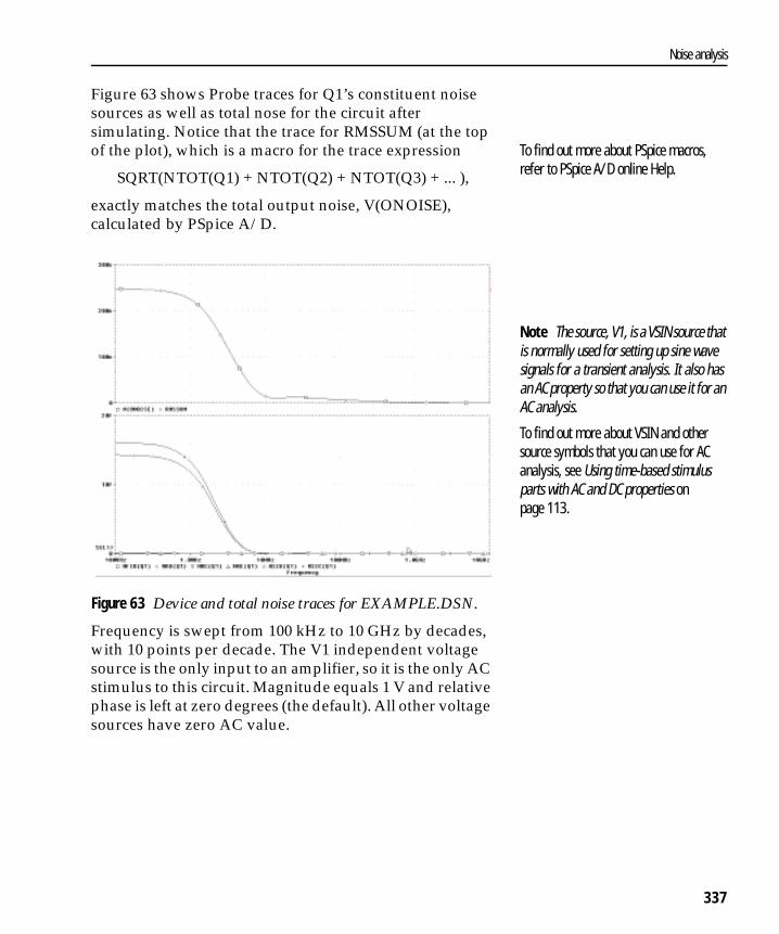
Figure 63 shows Probe traces for Q1’s constituent noise sources as well as total nose for the circuit after simulating. Notice that the trace for RMSSUM (at the top of the plot), which is a macro for the trace expression
SQRT(NTOT(Q1) + NTOT(Q2) + NTOT(Q3) + ... ),
exactly matches the total output noise, V(ONOISE), calculated by PSpice A/D.
Figure 63 Device and total noise traces for EXAMPLE.DSN.
Frequency is swept from 100 kHz to 10 GHz by decades, with 10 points per decade. The V1 independent voltage source is the only input to an amplifier, so it is the only AC stimulus to this circuit. Magnitude equals 1 V and relative phase is left at zero degrees (the default). All other voltage sources have zero AC value.
To find out more about PSpice macros, refer to PSpice A/D online Help.
Note The source, V1, is a VSIN source that is normally used for setting up sine wave signals for a transient analysis. It also has an AC property so that you can use it for an AC analysis.
To find out more about VSIN and other source symbols that you can use for AC analysis, see Using time-based stimulus parts with AC and DC properties on page 113.
Pspug.book Page 337 Tuesday, November 2, 1999 2:29 PM
Chapter 10 AC analyses
338
Pspug.book Page 338 Tuesday, November 2, 1999 2:29 PM