Company Confidential Psion Teklogix Employee Communications Meeting May 2006.

Psion TeklogixPowerScan® D8330/M8300
User ManualApril 22, 2008 Part No. 8100166.A
ISO 9001 Certified Quality Management System

Copyright © 2008 Psion Teklogix Inc. Mississauga, Ontario
All rights reserved. This document is an unpublished work and the infor-mation it contains is the property of Psion Teklogix, or its licensors, isissued in strict confidence, and may not be reproduced or copied, in wholeor in part, except with written consent from Psion Teklogix. Furthermore,this document is not to be used as a basis for design, manufacture, or sub-contract, or in any manner detrimental to the interests of Psion or its licen-sors. Psion®, Teklogix®, and all Psion Teklogix products and brand namesare trademarks of Psion Teklogix and its affiliates.
Windows® and the Windows Logo are trademarks or registered trade-marks of Microsoft Corporation in the United States and/orother countries.
All trademarks are the property of their respective holders.

Return-To-Factory Warranty
Psion Teklogix Inc. provides a return to factory warranty on this product fora period of twelve (12) months in accordance with the statement of Warrantyand Product Support provided at: www.psionteklogix.com/warrantyThe warranty on Psion Teklogix manufactured equipment does not extend toany product that has been tampered with, altered, or repaired by any personother than an employee of an authorized Psion Teklogix service organization.See Psion Teklogix terms and conditions of sale for full details.
Important: Psion Teklogix warranties take effect on the date of shipment.
Support Services And Worldwide Offices
Psion Teklogix provides a complete range of product support services to itscustomers worldwide. These services include technical support and productrepairs. Technical Support
For technical support in North America:Call Toll free: +1 800 387 8898 Option 3, or Direct Dial: +1 905 813 9900 Ext. 1999 Option 3
For technical support in EMEA (Europe, Middle East and Africa), pleasecontact the local office listed in the website below:http://www.psionteklogix.com/EMEASupport
For technical support in Asia, please contact the local office listed in thewebsite below:http://www.psionteklogix.com
Technical Support for Mobile Computing Products is provided via emailthrough the Psion Teklogix customer and partner extranets. To reach thewebsite, go to www.psionteklogix.com, and click on the appropriate Teknet linkon the home page. Then click on the “Login” button or the “Register” button,depending on whether you have previously registered for Teknet. Once youhave logged in, search for the “Support Request Form”.

Product Repairs
For repair service in North America:Call Toll free: +1 800 387 8898 Option 2, or Direct Dial: +1 905 813 9900 Ext. 1999 Option 2
For repair service in EMEA (Europe, Middle East and Africa), please con-tact the local office listed in the website below:http://www.psionteklogix.com/EMEASupport
For repair service in Asia, please contact the local office listed in the web-site below:http://www.psionteklogix.com
Worldwide Offices
COMPANY HEADQUARTERS CANADIAN SERVICE CENTRE
Psion Teklogix Inc. Psion Teklogix Inc.2100 Meadowvale Blvd. 7170 West Credit Ave., Unit #1Mississauga, Ontario Mississauga, OntarioCanada L5N 7J9 Canada L5N 7J9
Tel: +1 905 813 9900 Tel: +1 800 387 8898 Option 2 - or -Direct: + 1 905 813 9900 Ext. 1999, Option 2
Fax: +1 905 812 6300 Fax: + 1 905 812 6304E-mail: [email protected] E-mail: www.psionteklogix.com
NORTH AMERICAN HEADQUARTERS AND U.S. SERVICE CENTREPsion Teklogix Corp.3000 Kustom DriveHebron, KentuckyUSA 41048Tel: +1 859 371 6006Fax: +1 859 371 6422E-mail: [email protected]

INTERNATIONAL SUBSIDIARIES (see also www.psionteklogix.com/Subsidiaries)Psion Teklogix S.A.La Duranne, 135 Rue Rene DescartesBP 42100013591 Aix-En-ProvenceCedex 3; France
Tel: +33 4 42 90 88 09Fax: +33 4 42 90 88 88E-mail: [email protected]
Waste Electrical and Electronic Equipment (WEEE) Directive 2002/96/EC
This Product, and its accessories, comply with the requirements of the WasteElectrical and Electronic Equipment (WEEE) Directive 2002/96/EC. If yourend-of-life Psion Teklogix product or accessory carries a label as shownhere, please contact your local country representative for details on how toarrange recycling. For a list of international subsidiaries, please go to:www.psionteklogix.com/EnvironmentalCompliance
Restriction On Hazardous Substances (RoHS) Directive 2002/95/EC
What is RoHS?
The European Union has mandated that high environmental standards be metin the design and manufacture of electronic and electrical products sold inEurope, to reduce hazardous substances from entering the environment. The“Restriction on Hazardous Substances Directive (RoHS)” prescribes themaximum trace levels of lead, cadmium, mercury, hexavalent chromium,and flame retardants PBB and PBDE that may be contained in a product.Only products meeting these high environmental standards may be “placedon the market” in EU member states after July 1, 2006.RoHS Logo
Although there is no legal requirement to mark RoHS-compliant products,Psion Teklogix Inc. indicates its compliance with the directive as follows:

The RoHS logo located either on the back of the product or underneath thebattery in the battery compartment (or on a related accessory such as thecharger or docking station) signifies that the product is RoHS-compliant asper the EU directive. Other than as noted below, a Psion Teklogix productthat does not have an accompanying RoHS logo signifies that it was placedon the EU market prior to July 1, 2006, and is thereby exempt from thedirective.
Note: Not all accessories or peripherals will have a RoHS logo due to physical space limitations or as a result of their exempt status.
Disclaimer
Every effort has been made to make this material complete, accurate, and up-to-date. In addition, changes are periodically added to the information herein;these changes will be incorporated into new editions of the publication. Psion Teklogix Inc. reserves the right to make improvements and/orchanges in the product(s) and/or the program(s) described in this documentwithout notice, and shall not be responsible for any damages, including butnot limited to consequential damages, caused by reliance on the materialpresented, including but not limited to typographical errors.

COMPLIANCE This device must be opened by qualified personnel only. The batteries must be removed before opening the device. FCC COMPLIANCE Modifications or changes to this equipment without the express written approval of Psion Teklogix could void the authority to use the equipment.
This device complies with PART 15 of the FCC Rules. Operation is subject to the following two conditions: (1) This device may not cause harmful interference, and (2) this device must accept any interference received, including interference which may cause undesired operation.
FCC ID U4F0015. This equipment has been tested and found to comply with the limits for a Class B digital device, pursuant to Part 15 of the FCC Rules. These limits are designed to provide reasonable protection against harmful interference in a residential installation. This equipment generates, uses and can radiate radio frequency energy and, if not installed and used in accordance with the instructions, may cause harmful interference to radio communications. However, there is no guarantee that interference will not occur in a particular installation. If this equipment does cause harmful interference to radio or television reception, which can be determined by turning the equipment off and on, the user is encouraged to try to correct the interference by one of the following measures:
• Reorient or relocate the receiving antenna. • Increase the separation between the equipment and receiver. • Connect the equipment into an outlet on a circuit different from that to which the
receiver is connected. • Consult the dealer or an experienced radio/TV technician for help.
Emissions Information For Canada
This Class B digital apparatus meets all requirements of the Canadian Interference-Causing
Equipment Regulations. Cet appareil numérique de la classe B respecte toutes les exigences
du Règlement sur le matériel brouilleur du Canada.
RADIO COMPLIANCE Contact the competent authority responsible for the management of radio frequency devices of your country to verify any possible restrictions or licenses required. Refer to the web site http://europa.eu.int/comm/enterprise/rtte/spectr.htm for further information.

When used in a residential, commercial or light industrial environment the product and its approved UK and European peripherals fulfil all requirements for CE marking.
This equipment complies with the essential requirements of EU Directive 1999/5/EC (Declaration available: www.psionteklogix.com).
Cet équipement est conforme aux principales caractéristiques définies dans la Directive
européenne RTTE 1999/5/CE. (Déclaration disponible sur le site: www.psionteklogix.com).
Die Geräte erfüllen die grundlegenden Anforderungen der RTTE-Richtlinie (1999/5/EG). (Den
Wortlaut der Richtlinie finden Sie unter: www.psionteklogix.com).
Questa apparecchiatura è conforme ai requisiti essenziali della Direttiva Europea R&TTE
1999/5/CE. (Dichiarazione disponibile sul sito: www.psionteklogix.com).
Este equipo cumple los requisitos principales de la Directiva 1995/5/CE de la UE, “Equipos de
Terminales de Radio y Telecomunicaciones”. (Declaración disponible en:
www.psionteklogix.com).
Este equipamento cumpre os requisitos essenciais da Directiva 1999/5/CE do Parlamento
Europeu e do Conselho (Directiva RTT). (Declaração disponível no endereço:
www.psionteklogix.com).
Ο εξοπλισμός αυτός πληροί τις βασικές απαιτήσεις της κοινοτικής οδηγίας EU R&TTE
1999/5/EΚ. (Η δήλωση συμμόρφωσης διατίθεται στη διεύθυνση: www.psionteklogix.com)
Deze apparatuur voldoet aan de noodzakelijke vereisten van EU-richtlijn betreffende
radioapparatuur en telecommunicatie-eindappa-ratuur 199/5/EG. (verklaring beschikbaar:
www.psionteklogix.com).
Dette udstyr opfylder de Væsentlige krav i EU's direktiv 1999/5/EC om Radio- og
teleterminaludstyr. (Erklæring findes på: www.psionteklogix.com).
Dette utstyret er i overensstemmelse med hovedkravene i R&TTE-direktivet (1999/5/EC) fra EU.
(Erklæring finnes på: www.psionteklogix.com).
Utrustningen uppfyller kraven för EU-direktivet 1999/5/EC om ansluten teleutrustning och
ömsesidigt erkännande av utrustningens överensstämmelse (R&TTE). (Förklaringen finns att
läsa på: www.psionteklogix.com).
Tämä laite vastaa EU:n radio- ja telepäätelaitedirektiivin (EU R&TTE Directive 1999/5/EC)
vaatimuksia. (Julkilausuma nähtävillä osoitteessa: www.psionteklogix.com).

Psion Teklogix tímto prohlašuje, že PowerScan M8300 je ve shodì se základními požadavky a
dalšími pøíslušnými ustanoveními smìrnice 1995/5/ES (NV è. 426/2000 Sb.) a Prohlášení o
shodì je k dispozici na www.psionteklogix.com.
Toto zařízení lze provozovat v České republice na základě generální licence č. GL-12/R/2000.
Psion Teklogix týmto vyhlasuje, že PowerScan M8300 spĺň a základné požiadavky a všetky
príslušné ustanovenia Smernice 1995/5/ES (NV č. 443/2001 Z.z.) a Vyhlásenie o zhode je k
dispozícii na www.psionteklogix.com.
Toto zariadenie je možné prevádzkovat’ v Slovenskej republike na základe Všeobecného
povolenia č. VPR-01/2001. LASER SAFETY COMPLIANCE The laser scanner conforms to the applicable requirements of both CDRH 21 CFR 1040 and EN60825-1 at the date of manufacture.
The laser light is visible to the human eye and is emitted from the output window .
Laser warning and classification label .
CAUTION
Use of controls or adjustments or performance of procedures other than those specified herein may result in exposure to hazardous visible laser light.
The laser scanner utilizes a low-power laser diode. Although staring directly at the laser beam momentarily causes no known biological damage, avoid staring at the beam as one would with any very strong light source, such as the sun. Avoid that the laser beam hits the eye of an observer, even through reflective surfaces such as mirrors, etc.
The following information is shown on the laser scanner device class label:

ITALIANO DEUTSCH Classe 2: LUCE LASER
NON FISSARE IL RAGGIO APPARECCHIO LASER DI CLASSE 2
Klasse 2: LASERSTRAHLUNG NICHT IN DEN STRAHL PRODUKT DER LASERKLASSE 2
FRANÇAIS ESPAÑOL Classe 2: RAYON LASER
EVITER DE REGARDER LE RAYON APPAREIL LASER DE CLASSE 2
Clase 2: RAYO LÁSER NO MIRAR FIJO EL RAYO APARATO LÁSER DE CLASE 2
LED CLASS Class 1 LED product. This product conforms to EN60825-1:2001. IC (INDUSTRY CANADA) Operation is subject to the following two conditions: (1) this device may not cause interference, and (2) this device must accept any interference, including interference that may cause undesired operation of the device.
LASER RADIATION - DO NOT STARE INTO BEAM
CLASS 2 LASER PRODUCT (IEC) CLASS II LASER PRODUCT (CDRH) MAX. OUTPUT RADIATION 1.4 mW
EMITTED WAVELENGTH 630~680 nm EN60825-1: 2001
CAUTION - CLASS 2 LASERLIGHT WHEN OPEN
AVOID EXPOSURE – LASER LIGHT IS EMITTED FROM THIS APERTURE
DO NOT STARE INTO BEAM
This product complies with 21 CFR Subchapter J

Psion Teklogix Inc.
2100 Meadowvale Boulevard, Mississauga, Ontario, Canada L5N 7J9
http:\\www.psionteklogix.com 08
dichiara che declares that the déclare que le bescheinigt, daß das Gerät declare que el PowerScan Mxxx; Cordless Bar code Reader
e tutti i suoi modelli and all its models et tous ses modèles und seine Modelle y todos sus modelos
sono conformi alle Direttive del Consiglio Europeo sottoelencate: are in conformity with the requirements of the European Council Directives listed below: sont conformes aux spécifications des Directives de l'Union Européenne ci-dessous: den nachstehenden angeführten Direktiven des Europäischen Rats: cumple con los requisitos de las Directivas del Consejo Europeo, según la lista siguiente:
1999/5/EEC R&TTE Questa dichiarazione è basata sulla conformità dei prodotti alle norme seguenti: This declaration is based upon compliance of the products to the following standards: Cette déclaration repose sur la conformité des produits aux normes suivantes: Diese Erklärung basiert darauf, daß das Produkt den folgenden Normen entspricht: Esta declaración se basa en el cumplimiento de los productos con la siguientes normas:
ETSI EN 301 489-3 V1.4.1, AUGUST 2002 : ELECTROMAGNETIC COMPATIBILITY AND RADIO SPECTRUM MATTERS
(ERM); ELECTROMAGNETIC COMPATIBILITY (EMC) STANDARD FOR RADIO EQUIPMENT AND SERVICES; PART 3: SPECIFIC CONDITIONS FOR SHORT-RANGE DEVICES (SRD) OPERATING ON FREQUENCIES BETWEEN 9KHZ AND 40GHZ
ETSI EN 300 220-3 V1.1.1, SEPTEMBER 2000 : ELECTROMAGNETIC COMPATIBILITY AND RADIO SPECTRUM MATTERS (ERM); SHORT RANGE DEVICES (SRD); RADIO EQUIPMENT TO BE USED IN THE 25MHZ TO 1000MHZ FREQUENCY RANGE WITH POWER LEVELS RANGING UP TO 500MW; PART 3: HARMONIZED EN COVERING ESSENTIAL REQUIREMENTS UNDER ARTICLE 3.2 OF THE R&TTE DIRECTIVE
EN 60950-1, DECEMBER 2001 : INFORMATION TECHNOLOGY EQUIPMENT - SAFETY - PART 1 : GENERAL REQUIREMENTS
April 16, 2008

NOTES
iii
CONTENTS
1 INTRODUCTION .......................................................................................... 1
2 INSTALLATION............................................................................................ 2 2.1 PowerScan® D8330 Interface Cable Connections ........................................2 2.2 BC-80X0 Interface Cable Connections .........................................................4 2.3 RS-232 Connection.......................................................................................5 2.4 USB ..............................................................................................................5 2.5 IBM USB POS...............................................................................................6 2.6 WEDGE Connection .....................................................................................7 2.7 PEN Emulation Connection...........................................................................7 2.8 Network Connections....................................................................................8 2.8.1 BC-8060 Network Connectors ...................................................................... 8 2.8.2 Network Cabling............................................................................................ 9 2.8.3 Network Termination................................................................................... 10 2.9 PowerScan® M8300 Battery Maintenance .................................................. 11 2.9.1 Battery Charging ......................................................................................... 11 2.9.2 Replacing PowerScan® M8300 Batteries .................................................... 11 2.10 Mounting The BC-80X0 / C-8000 Cradle .................................................... 12 2.10.1 Desktop Mounting ....................................................................................... 13 2.10.2 Wall Mounting ............................................................................................. 16
3 POWERSCAN® M8300 SYSTEM AND NETWORK LAYOUTS.................. 18 3.1 Stand-alone Layouts ...................................................................................18 3.1.1 Point-to-Point Reader Layout...................................................................... 18 3.1.2 Stand-Alone Layout with Multiple Readers ................................................. 18 3.1.3 Multiple Stand-Alone Layouts ..................................................................... 19 3.1.4 C-BOX Layout............................................................................................. 20 3.2 Multidrop STAR-System™ Network Layouts .............................................. 21 3.2.1 Host Master Layout..................................................................................... 21 3.2.2 BC-8060 Master Layout .............................................................................. 22 3.2.3 Master BC-8060 Network Troubleshooting ................................................. 23
4 CONFIGURATION...................................................................................... 24 4.1 Configuration Methods................................................................................24 4.1.1 Reading Configuration Bar Codes .............................................................. 24 4.1.2 Using the Original Manufacturer’s Datalogic Aladdin™ .............................. 24 4.1.3 Copy Command .......................................................................................... 25 4.1.4 Sending Configuration Strings from Host.................................................... 25 4.2 Setup Procedures .......................................................................................25 4.3 PowerScan® D8330 Setup ..........................................................................27 4.4 PowerScan® M8300/BC-80X0 Point-to-Point Setup ................................... 27 4.5 PowerScan® M8300/BC-80X0 Stand-Alone Setup ..................................... 28 4.5.1 Using Multiple M-Series Readers with Same Cradle .................................. 30 4.5.2 PowerScan® M8300/STAR-Modem™ in Stand-Alone Mode ...................... 31
iv
4.6 PowerScan® M8300/STAR-System™ Setup .............................................. 32 4.7 BC-8060 STAR-System™ Network Setup .................................................. 34 4.8 Interface Selection ......................................................................................36 4.9 USB Reader Configuration..........................................................................39 4.10 Changing Default Settings ..........................................................................41
5 REFERENCES ......................................................................................... 140 5.1 RS-232 Parameters .................................................................................. 140 5.1.1 Handshaking ............................................................................................. 140 5.1.2 ACK/NACK Protocol ................................................................................. 141 5.1.3 FIFO.......................................................................................................... 142 5.1.4 RX Timeout ............................................................................................... 143 5.2 Pen Parameters ........................................................................................143 5.2.1 Minimum Output Pulse.............................................................................. 143 5.2.2 Conversion to Code 39 and Code 128...................................................... 143 5.2.3 Overflow.................................................................................................... 144 5.2.4 Output and Idle Levels .............................................................................. 144 5.2.5 Inter-Block Delay....................................................................................... 145 5.3 Network Parameters ................................................................................. 145 5.3.1 Slave Address Range First/Last................................................................ 145 5.3.2 Network Warning Message....................................................................... 145 5.3.3 Reception Warning Message.................................................................... 146 5.3.4 Master Header/Terminator Selection ........................................................ 146 5.4 Data Format ..............................................................................................146 5.4.1 Header/Terminator Selection .................................................................... 146 5.4.2 Define Special Key Sequence................................................................... 148 5.4.3 Address Stamping..................................................................................... 155 5.4.4 Address Delimiter...................................................................................... 155 5.4.5 Time Stamping Format ............................................................................. 156 5.4.6 Time Stamping Delimiter........................................................................... 156 5.5 Power Save............................................................................................... 156 5.5.1 Sleep State ............................................................................................... 156 5.5.2 Enter Sleep Timeout ................................................................................. 157 5.6 Reading Parameters ................................................................................. 157 5.6.1 Trigger Signal............................................................................................ 157 5.6.2 Trigger Click.............................................................................................. 157 5.6.3 Trigger-Off Timeout................................................................................... 157 5.6.4 Reads per Cycle ....................................................................................... 157 5.6.5 Safety Time............................................................................................... 158 5.7 Decoding Parameters ............................................................................... 158 5.7.1 Ink-Spread ................................................................................................ 158 5.7.2 Overflow Control ....................................................................................... 158 5.7.3 Interdigit Control........................................................................................ 159 5.8 Advanced Formatting................................................................................ 159 5.8.1 Match Conditions ...................................................................................... 159 5.9 Radio Parameters (M8300 Series Only) ................................................... 159
v
5.9.1 Radio Protocol Timeout ............................................................................ 159 5.9.2 Radio RX Timeout..................................................................................... 160 5.9.3 Power-Off Timeout.................................................................................... 160 5.9.4 Transmission Mode................................................................................... 161 5.9.5 Beeper Control for Radio Response ......................................................... 161 5.9.6 Single Store .............................................................................................. 162 5.9.7 Batch Mode............................................................................................... 162 5.9.8 Find Me (PowerScan® M8300 only) .......................................................... 163 5.10 Display Parameters (Some M8300 Models only) ...................................... 164 5.10.1 Display Mode ............................................................................................ 164 5.11 Configuration Editing Commands ............................................................. 165 5.12 Custom Default Configuration ................................................................... 166 5.13 Code Type Recognition ............................................................................ 166 5.14 Configuration Copying Commands ........................................................... 167 5.14.1 Copy PowerScan® D8330 Series.............................................................. 167 5.14.2 Copy PowerScan® M8300 Series ............................................................. 168 5.14.3 Copy BC-80X0 .......................................................................................... 169 5.15 Default Parameters for POS Terminals..................................................... 170 5.16 Firmware Upgrade .................................................................................... 171
6 MESSAGE FORMATTING ....................................................................... 172 6.1 Messages from Host to Reader ................................................................ 172 6.1.1 Cursor Control........................................................................................... 173 6.1.2 Font Selection ........................................................................................... 174 6.1.3 Clearing Display........................................................................................ 174 6.1.4 LED and Beeper Control ........................................................................... 174 6.1.5 Setting RTC .............................................................................................. 175 6.2 Messages from SCANNER Command Keys............................................. 175
7 TECHNICAL FEATURES......................................................................... 177 7.1 PowerScan® D8330 .................................................................................. 177 7.2 PowerScan® M8300..................................................................................178 7.3 BC-80X0 / C-8000..................................................................................... 179 7.4 System and Radio Features...................................................................... 180 7.5 Status Indicators .......................................................................................180 7.6 Reading Diagrams .................................................................................... 183
vi
GENERAL VIEW
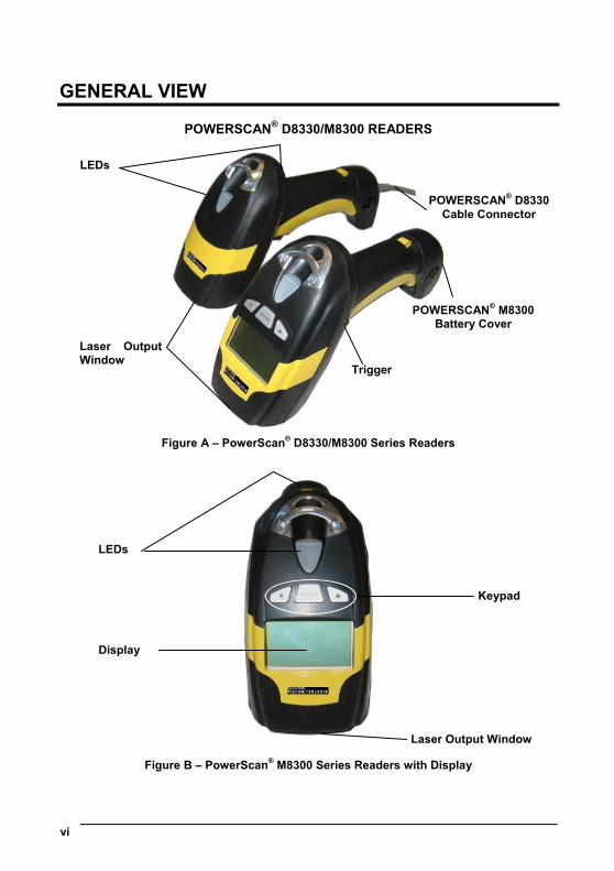
POWERSCAN® D8330/M8300 READERS
Figure A – PowerScan® D8330/M8300 Series Readers
Figure B – PowerScan® M8300 Series Readers with Display
LEDs
Keypad
Display
Laser Output Window
Laser OutputWindow
POWERSCAN® M8300 Battery Cover
POWERSCAN® D8330 Cable Connector
LEDs
Trigger
vii
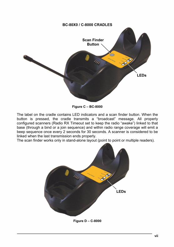
BC-80X0 / C-8000 CRADLES
Figure C – BC-8000
The label on the cradle contains LED indicators and a scan finder button. When the button is pressed, the cradle transmits a “broadcast” message. All properly configured scanners (Radio RX Timeout set to keep the radio “awake”) linked to that base (through a bind or a join sequence) and within radio range coverage will emit a beep sequence once every 2 seconds for 30 seconds. A scanner is considered to be linked when the last transmission ends properly. The scan finder works only in stand-alone layout (point to point or multiple readers).
Figure D – C-8000
LEDs
LEDs
Scan Finder Button

INTRODUCTION
1
1 INTRODUCTION Psion Teklogix renews its range of industrial laser scanners introducing the PowerScan® family: PowerScan® D8330 and PowerScan® M8300. Robustness and ergonomics remain unsurpassed: clearly audible beeper and bright "good read" LEDs for areas where noise levels are normally high; the aim mode, which helps point to the right code, has now been extended to the whole PowerScan® family. Optical parts are completely suspended on shock absorbers and a careful choice of the body materials, such as the co-moulded rubber, protect the PowerScan® from damage due to "falls". New enhanced architecture, based on an M16 high-speed microprocessor, enables exceptional performance for promptness and reading speed of standard codes as well as the ability to read poorly printed and damaged codes. Patented Puzzle Solver Technology™ adds further strength to the PowerScan® powerful engine. In all applications where mobility is a value, the new PowerScan® M8300 represents the key to increase productivity and flexibility in the working area. PowerScan® M8300 communicates through a low power, license-free radio in the 433 MHz band (910 MHz for USA version) and allows bi-directional communication between the base station and the host. PowerScan® M8300 also includes a display and a 3 push-button keypad. Thanks to these features, the operator can receive information from the host, interact with the central system and visualize the code read. The cordless system offers scalable solutions to solve simple applications and complex projects:
• Point to point: each reader is associated with its own base station;
• Multipoint: up to 32 readers transmit data to one base station;
• Network: to cover a wide area, connecting up to 16 bases and 512 readers simultaneously working in automatic roaming.
PowerScan® M8300 is 100% compatible with STAR-System™, the new Psion Teklogix RF narrow band solution for mobile applications that provides the widest family of narrow band devices on the market. Your PowerScan® reader is supplied with its own Quick Reference Guide, which provides connection, diagrams, reading diagrams, basic application parameter settings, default values, and specific technical features. You can use either the Quick Reference Guide or this Manual for initial configuration in order to set the default values and select the interface for your application. This manual provides all the necessary information for complete mechanical installation and system software configuration.
POWERSCAN® D8330/M8300
2
2 INSTALLATION
CAUTION
Connections should always be made with power OFF!
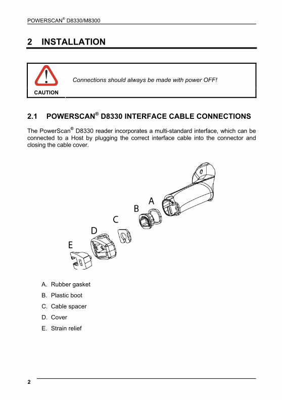
2.1 POWERSCAN® D8330 INTERFACE CABLE CONNECTIONS The PowerScan® D8330 reader incorporates a multi-standard interface, which can be connected to a Host by plugging the correct interface cable into the connector and closing the cable cover.
A. Rubber gasket
B. Plastic boot
C. Cable spacer
D. Cover
E. Strain relief
INSTALLATION
3
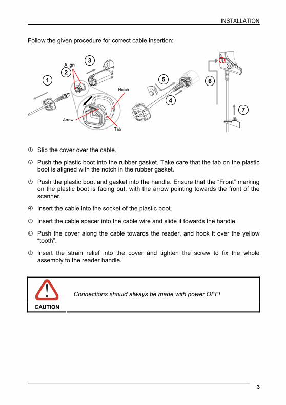
Follow the given procedure for correct cable insertion:
Slip the cover over the cable.
Push the plastic boot into the rubber gasket. Take care that the tab on the plastic boot is aligned with the notch in the rubber gasket.
Push the plastic boot and gasket into the handle. Ensure that the “Front” marking on the plastic boot is facing out, with the arrow pointing towards the front of the scanner.
Insert the cable into the socket of the plastic boot.
Insert the cable spacer into the cable wire and slide it towards the handle.
Push the cover along the cable towards the reader, and hook it over the yellow “tooth”.
Insert the strain relief into the cover and tighten the screw to fix the whole assembly to the reader handle.
CAUTION
Connections should always be made with power OFF!
Align
1 2
3
4
5 6
7
Notch
Tab
Arrow
POWERSCAN® D8330/M8300
4
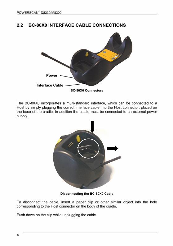
2.2 BC-80X0 INTERFACE CABLE CONNECTIONS
BC-80X0 Connectors
The BC-80X0 incorporates a multi-standard interface, which can be connected to a Host by simply plugging the correct interface cable into the Host connector, placed on the base of the cradle. In addition the cradle must be connected to an external power supply.
Disconnecting the BC-80X0 Cable
To disconnect the cable, insert a paper clip or other similar object into the hole corresponding to the Host connector on the body of the cradle. Push down on the clip while unplugging the cable.
Interface Cable
Power
INSTALLATION
5
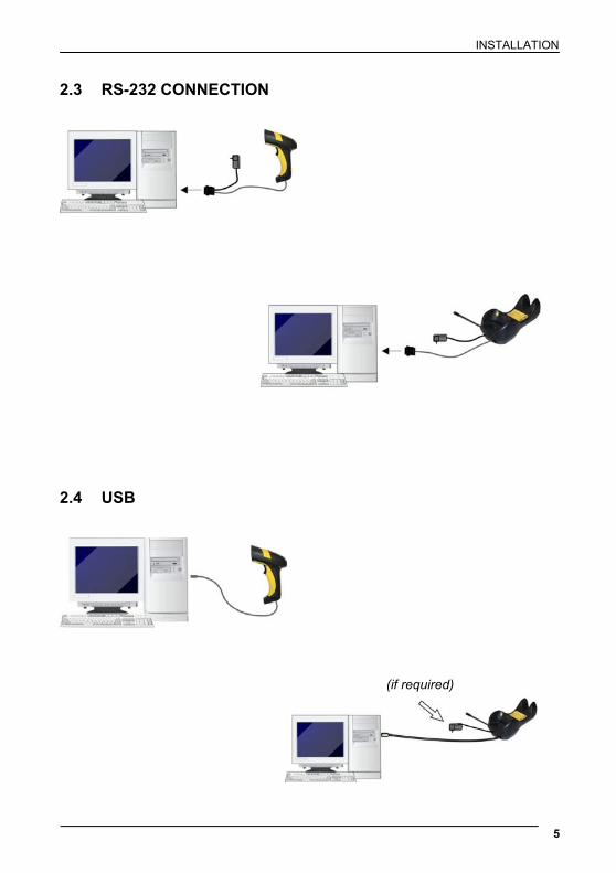
2.3 RS-232 CONNECTION
2.4 USB
(if required)
POWERSCAN® D8330/M8300
6
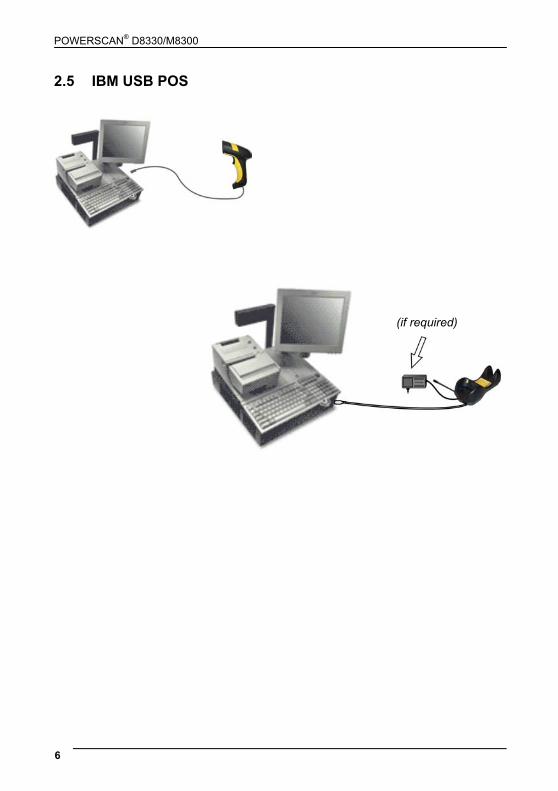
2.5 IBM USB POS
(if required)

INSTALLATION
7
2.6 WEDGE CONNECTION
2.7 PEN EMULATION CONNECTION
POWERSCAN® D8330/M8300
8
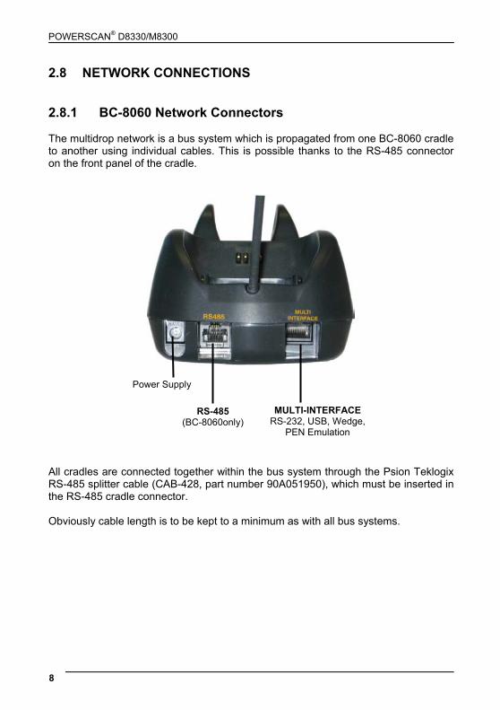
2.8 NETWORK CONNECTIONS 2.8.1 BC-8060 Network Connectors The multidrop network is a bus system which is propagated from one BC-8060 cradle to another using individual cables. This is possible thanks to the RS-485 connector on the front panel of the cradle.
All cradles are connected together within the bus system through the Psion Teklogix RS-485 splitter cable (CAB-428, part number 90A051950), which must be inserted in the RS-485 cradle connector. Obviously cable length is to be kept to a minimum as with all bus systems.
Power Supply
RS-485 (BC-8060only)
MULTI-INTERFACE RS-232, USB, Wedge,
PEN Emulation
INSTALLATION
9
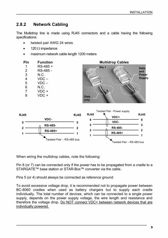
2.8.2 Network Cabling The Multidrop line is made using RJ45 connectors and a cable having the following specifications:
• twisted pair AWG 24 wires • 120 Ω impedance • maximum network cable length 1200 meters
Pin Function Multidrop Cables 1 RS-485 + 2 RS-485 - 3 N.C. 4 VDC – 5 VDC – 6 N.C. 7 VDC + 8 VDC +
5
2
RJ45
5
2
RJ45
1 1
VDC-
RS-485-
RS-485+
Twisted Pair – RS-485 bus
8
5
2
RJ45
8
5
2
RJ45
1 1
Twisted Pair – RS-485 bus
Twisted Pair - Power supply
VDC+VDC-
RS-485-
RS-485+
When wiring the multidrop cables, note the following: Pin 8 (or 7) can be connected only if the power has to be propagated from a cradle to a STARGATE™ base station or STAR-Box™ converter via the cable. Pins 5 (or 4) should always be connected as reference ground. To avoid excessive voltage drop, it is recommended not to propagate power between BC-8060 cradles when used as battery chargers but to supply each cradle individually. The total number of devices, which can be connected to a single power supply, depends on the power supply voltage, the wire length and resistance and therefore the voltage drop. Do NOT connect VDC+ between network devices that are individually powered.
Data only
Data and Power Supply
Pin 1
POWERSCAN® D8330/M8300
10
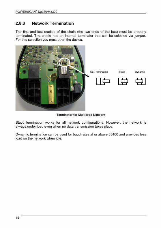
2.8.3 Network Termination The first and last cradles of the chain (the two ends of the bus) must be properly terminated. The cradle has an internal terminator that can be selected via jumper. For this selection you must open the device.
No Termination Static Dynamic
Terminator for Multidrop Network Static termination works for all network configurations. However, the network is always under load even when no data transmission takes place. Dynamic termination can be used for baud rates at or above 38400 and provides less load on the network when idle.

INSTALLATION
11
2.9 POWERSCAN® M8300 BATTERY MAINTENANCE 2.9.1 Battery Charging Once the system is connected and powered, you can place the PowerScan® M8300 into the cradle to charge the battery. When the reader is correctly inserted in the cradle, the "Reader" red LED on the cradle goes on to indicate that the battery is charging. The "Reader" green LED on the cradle goes on when the battery is completely charged. 2.9.2 Replacing PowerScan® M8300 Batteries To change the batteries in your PowerScan® M8300 scanner, press the black button or unscrew the fixing screw on the handle cover and extract the battery pack from the reader handle.
NOTE
When the batteries are extracted from the scanner, the timer maintains the current hour and date for about 1 minute.
Replace the old battery pack with a new one by inserting it within the reader handle and pushing it until it clicks.
WARNING
Do not incinerate, disassemble, short terminals or expose to high temperature. Risk of fire, explosion. Use specified charger only. Risk of explosion if the battery is replaced by an incorrect type. Dispose of the batteries as required by the relevant laws in force.
1
2

POWERSCAN® D8330/M8300
12
2.10 MOUNTING THE BC-80X0 / C-8000 CRADLE The cradle package contains the following items: BC-80X0 / C-8000 Cradle BC-80X0 Cradle Quick Reference Guide / C-8000 Cradle Quick Reference Guide BC-8000 Antenna 2 wall-mounting lock hinges 2 adhesive strips 4 rubber feet 1 horizontal base 1 inclined base
The cradle (either BC-80X0 or C-8000) can be mounted for portable or fixed desktop usage, or it can be fixed to a wall. The horizontal base allows portable and fixed desktop usage, while the inclined base provides desktop and wall mounting guaranteeing a comfortable handling of the PowerScan® M8300 reader.
BC-80X0/C-8000 Cradle mounted on the Horizontal Base
BC-80X0/C-8000 Cradle mounted on the Inclined Base

INSTALLATION
13
2.10.1 Desktop Mounting For desktop usage, you can mount the cradle either on the horizontal base, for reduced overall dimensions, or on the inclined base for a more ergonomic taking out and insertion of the reader onto the cradle.
Horizontal base
Top View Bottom View
Inclined base
Top View Bottom View
Mounting Tabs (4)
Mounting Holes (2)
Rubber Foot Seat (4)
Adhesive Strip Seat (2)
Cable Channels
Mounting Tabs (4)
Mounting Holes (4)
Cable Channels
Adhesive Strip Seat (2)
Rubber Foot Seat (4)
POWERSCAN® D8330/M8300
14
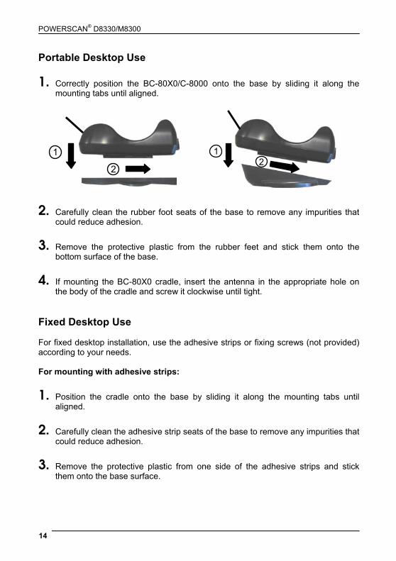
Portable Desktop Use
1. Correctly position the BC-80X0/C-8000 onto the base by sliding it along the mounting tabs until aligned.
1
2
12
2. Carefully clean the rubber foot seats of the base to remove any impurities that could reduce adhesion.
3. Remove the protective plastic from the rubber feet and stick them onto the bottom surface of the base.
4. If mounting the BC-80X0 cradle, insert the antenna in the appropriate hole on the body of the cradle and screw it clockwise until tight.
Fixed Desktop Use For fixed desktop installation, use the adhesive strips or fixing screws (not provided) according to your needs. For mounting with adhesive strips:
1. Position the cradle onto the base by sliding it along the mounting tabs until aligned.
2. Carefully clean the adhesive strip seats of the base to remove any impurities that could reduce adhesion.
3. Remove the protective plastic from one side of the adhesive strips and stick them onto the base surface.
INSTALLATION
15
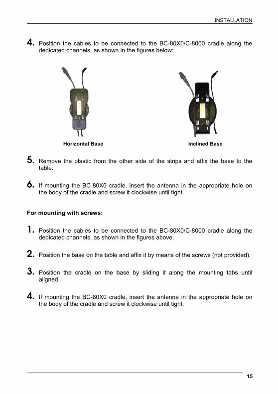
4. Position the cables to be connected to the BC-80X0/C-8000 cradle along the dedicated channels, as shown in the figures below:
Horizontal Base Inclined Base
5. Remove the plastic from the other side of the strips and affix the base to the table.
6. If mounting the BC-80X0 cradle, insert the antenna in the appropriate hole on the body of the cradle and screw it clockwise until tight.
For mounting with screws:
1. Position the cables to be connected to the BC-80X0/C-8000 cradle along the dedicated channels, as shown in the figures above.
2. Position the base on the table and affix it by means of the screws (not provided).
3. Position the cradle on the base by sliding it along the mounting tabs until aligned.
4. If mounting the BC-80X0 cradle, insert the antenna in the appropriate hole on the body of the cradle and screw it clockwise until tight.
POWERSCAN® D8330/M8300
16
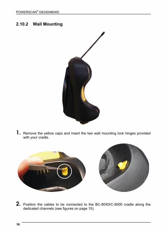
2.10.2 Wall Mounting
1. Remove the yellow caps and insert the two wall mounting lock hinges provided with your cradle.
2. Position the cables to be connected to the BC-80X0/C-8000 cradle along the dedicated channels (see figures on page 15).

INSTALLATION
17
If using the adhesive strips: a. Carefully clean the adhesive strip
seats of the base to remove any impurities that could reduce adhesion.
b. Remove the protective plastic from
one side of the adhesive strips and stick them onto the base surface.
c. Remove the plastic from the other
side of the strips and affix the base to the wall as indicated in the figure below.
If using the mounting screws:
3. Using the mounting holes on the base as a pattern, mark the wall where you desire to mount the BC-80X0/C-8000.
4. Drill the appropriate size holes and insert the threaded dowels (not provided) into the holes.
5. Position the base on the wall as indicated in the figure below and affix it by means of the screws (not provided).
Inclined Base Wall-mounting
6. Attach the cradle on the base by sliding it along the mounting tabs until aligned.
7. If mounting the BC-80X0 cradle, insert the antenna in the appropriate hole on the body of the cradle and screw it clockwise until tight.
POWERSCAN® D8330/M8300
18
3 POWERSCAN® M8300 SYSTEM AND NETWORK LAYOUTS
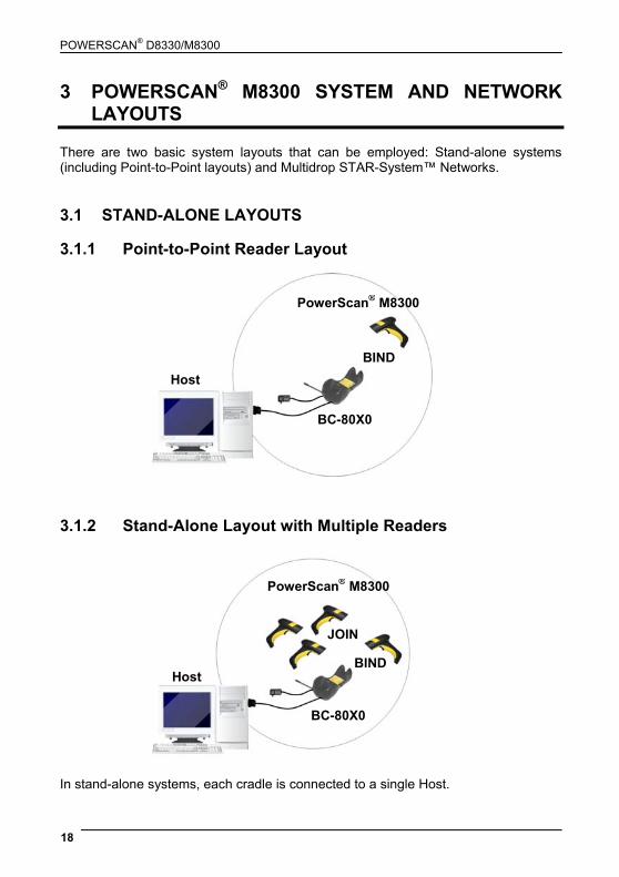
There are two basic system layouts that can be employed: Stand-alone systems (including Point-to-Point layouts) and Multidrop STAR-System™ Networks. 3.1 STAND-ALONE LAYOUTS 3.1.1 Point-to-Point Reader Layout
Host
BC-80X0
BIND
PowerScan® M8300
3.1.2 Stand-Alone Layout with Multiple Readers
Host
PowerScan® M8300
BC-80X0
JOIN
BIND
In stand-alone systems, each cradle is connected to a single Host.

POWERSCAN® M8300 SYSTEM AND NETWORK LAYOUTS
19
3.1.3 Multiple Stand-Alone Layouts Many stand-alone connections can operate in the same physical area without interference, provided all readers and cradles in the system have different addresses.
Multiple Stand-alone Systems in the Same Area
Since the cradles can communicate to multiple PowerScan® M8300 readers, you might find it useful to employ one or more C-8000 battery chargers in addition to the BC-80X0 cradle, so that the battery re-charging operation can be performed for several scanners at the same time.
Host
Host
Host
PowerScan® M8300
BC-80X0 BC-80X0
BC-80X0
BIND BIND
BIND
JOIN
JOIN
PowerScan® M8300
PowerScan® M8300
POWERSCAN® D8330/M8300
20
3.1.4 C-BOX Layout
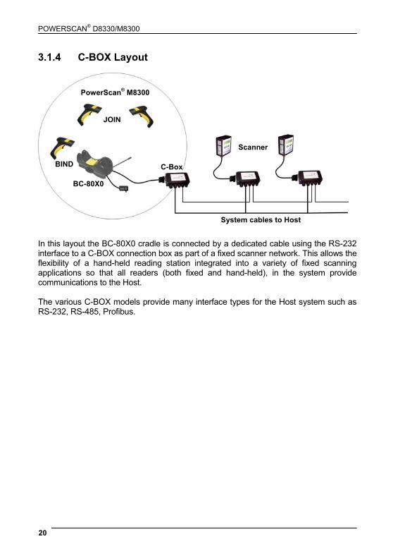
In this layout the BC-80X0 cradle is connected by a dedicated cable using the RS-232 interface to a C-BOX connection box as part of a fixed scanner network. This allows the flexibility of a hand-held reading station integrated into a variety of fixed scanning applications so that all readers (both fixed and hand-held), in the system provide communications to the Host. The various C-BOX models provide many interface types for the Host system such as RS-232, RS-485, Profibus.
JOIN
BIND
BC-80X0
C-Box
Scanner
System cables to Host
PowerScan® M8300
POWERSCAN® M8300 SYSTEM AND NETWORK LAYOUTS
21
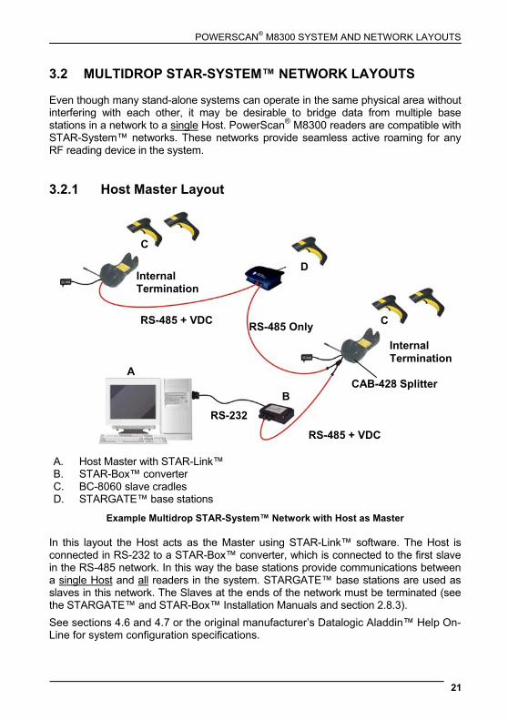
3.2 MULTIDROP STAR-SYSTEM™ NETWORK LAYOUTS Even though many stand-alone systems can operate in the same physical area without interfering with each other, it may be desirable to bridge data from multiple base stations in a network to a single Host. PowerScan® M8300 readers are compatible with STAR-System™ networks. These networks provide seamless active roaming for any RF reading device in the system. 3.2.1 Host Master Layout
A. Host Master with STAR-Link™ B. STAR-Box™ converter C. BC-8060 slave cradles D. STARGATE™ base stations
Example Multidrop STAR-System™ Network with Host as Master In this layout the Host acts as the Master using STAR-Link™ software. The Host is connected in RS-232 to a STAR-Box™ converter, which is connected to the first slave in the RS-485 network. In this way the base stations provide communications between a single Host and all readers in the system. STARGATE™ base stations are used as slaves in this network. The Slaves at the ends of the network must be terminated (see the STARGATE™ and STAR-Box™ Installation Manuals and section 2.8.3). See sections 4.6 and 4.7 or the original manufacturer’s Datalogic Aladdin™ Help On-Line for system configuration specifications.
Internal Termination
Internal Termination
RS-485 + VDC
RS-485 + VDC
RS-232
A
B
C
C
D
RS-485 Only
CAB-428 Splitter
POWERSCAN® D8330/M8300
22
3.2.2 BC-8060 Master Layout
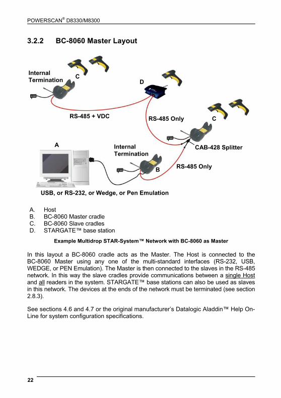
A. Host B. BC-8060 Master cradle C. BC-8060 Slave cradles D. STARGATE™ base station
Example Multidrop STAR-System™ Network with BC-8060 as Master In this layout a BC-8060 cradle acts as the Master. The Host is connected to the BC-8060 Master using any one of the multi-standard interfaces (RS-232, USB, WEDGE, or PEN Emulation). The Master is then connected to the slaves in the RS-485 network. In this way the slave cradles provide communications between a single Host and all readers in the system. STARGATE™ base stations can also be used as slaves in this network. The devices at the ends of the network must be terminated (see section 2.8.3). See sections 4.6 and 4.7 or the original manufacturer’s Datalogic Aladdin™ Help On-Line for system configuration specifications.
Internal Termination
InternalTermination
RS-485 + VDC
RS-485 Only
USB, or RS-232, or Wedge, or Pen Emulation
A
B
C
C D
RS-485 Only
CAB-428 Splitter
POWERSCAN® M8300 SYSTEM AND NETWORK LAYOUTS
23
3.2.3 Master BC-8060 Network Troubleshooting Two diagnostic strings can be sent via RS-232 from the Host to the Master cradle in order to have feedback about the network itself. #+LSlave Returns a list of all the Slaves recognized at boot up. Example: In a network where the Master cradle has address 0188 and one Slave cradle with address 0001, the response is:
188 1
#+Alive<xxxx> Executes a continuous Alive request to the slave xxxx in order to monitor the performance of the connection. A diagnostic message is displayed on the Host. Example: If this command is sent for slave cradle with address 0032, the response is:
/*32: BC-80X0 SOFTWARE RELEASE 1.00 20/10/2006*/ if there are no communication errors /*32: FAIL*/ if there are communication errors.
To exit from this command, reset the system by cycling power to the Master cradle.
POWERSCAN® D8330/M8300
24
4 CONFIGURATION 4.1 CONFIGURATION METHODS 4.1.1 Reading Configuration Bar Codes This manual can be used for complete setup and configuration of your reader by following the setup procedures in this chapter (see section 4.2 for an overview). If you wish to change the default settings, this manual provides complete configuration of your reader in an easy way.
To configure your reader:
1) Open the folded page in Appendix C with the hex-numeric table and keep it open during the device configuration.
2) Read the Enter Configuration code ONCE, available at the top of each page of configuration.
3) Modify the desired parameters in one or more sections following the procedures given for each group.
4) Read the Exit and Save Configuration code ONCE, available at the top of each page of configuration.
Reference notes describing the operation of the more complex parameters are given in chapter 5. 4.1.2 Using the Original Manufacturer’s Datalogic
Aladdin™ The original manufacturer’s Datalogic Aladdin™ is a multi-platform utility program providing a quick and user-friendly configuration method via the RS-232/USB-COM interface. It also allows upgrading the software of the connected device (see the original manufacturer’s Datalogic Aladdin™ Help On-Line for more details).
CONFIGURATION
25
4.1.3 Copy Command A previously configured device (Master), can be used to send its configuration directly to other devices of the same type (Slaves). The particular procedure for each device is given in section 5.14. 4.1.4 Sending Configuration Strings from Host An alternative configuration method is provided in Appendix A using the RS-232 interface. This method is particularly useful when many devices need to be configured with the same settings. Batch files containing the desired parameter settings can be prepared to configure devices quickly and easily. 4.2 SETUP PROCEDURES For PowerScan® D8330 Series readers, follow the setup procedures in sections 4.3, and 4.8.
For PowerScan® M8300 Series readers, the setup procedures depend on two basic applications, Stand-alone or STAR-System™.
Stand-alone applications allow communication with the Host by either the BC-80X0 cradle (section 4.5), or by the STAR-Modem™ radio modem (section 4.5.2).
STAR-System™ applications allow communication with the Host through an RS-485 network by the STARGATE™ RF base station or by the BC-8000 cradle (sections 4.6 and 4.7).
Proceed as shown in the following diagram:
POWERSCAN® D8330/M8300
26
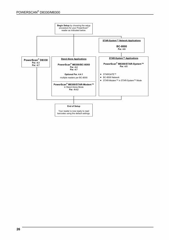
Begin Setup by choosing the setup procedure for your PowerScan®
reader as indicated below.
End of Setup
Your reader is now ready to read barcodes using the default settings.
Stand Alone Applications
PowerScan® M8300/BC-80X0 Par. 4.4 Par. 4.7
Optional Par. 4.4.1
multiple readers per BC-8000
PowerScan® M8300/STAR-Modem™ in Stand Alone Mode
Par. 4.4.2
PowerScan® D8330 Par. 4.3 Par. 4.7
STAR-System™ Network Applications
BC-8000 Par. 4.6
STAR-System™ Applications
PowerScan® M8300/STAR-System™ Par. 4.5
• STARGATE™ • BC-8000 Network • STAR-Modem™ in STAR-System™ Mode
CONFIGURATION
27
4.3 POWERSCAN® D8330 SETUP
1. Read the restore default parameters code below. Restore PowerScan® D8330 Default
Ì$+$*oÎ After reading the above code, go to section 4.8 Interface Selection.
4.4 POWERSCAN® M8300/BC-80X0 POINT-TO-POINT SETUP A rapid configuration procedure has been devised for point-to-point applications where a single reader is associated exclusively with its own BC-80X0 base station and where it is not necessary to set the Date and Time parameters.
A special pre-printed bind-address label provided in the BC-80X0 base station package can be used to bind the PowerScan® M8300 reader to the base station with the address coded on the label. The address is also written numerically on the label to be easily recognized. Valid addresses are in the range from 0000 to 1999. Make sure that all cradles used in the same area have different addresses.
To rapidly configure your point-to-point application: 1. Apply the bind-address label onto the BC-80X0 base station as indicated in
the BC-80X0 Quick Reference Guide.
2. When the BC-80X0 cradle is connected and powered, read the Bind-Address label to pair the PowerScan® M8300 to the BC-80X0 cradle.
The green LED on the PowerScan® M8300 will blink: the reader is ready to be positioned onto the cradle.
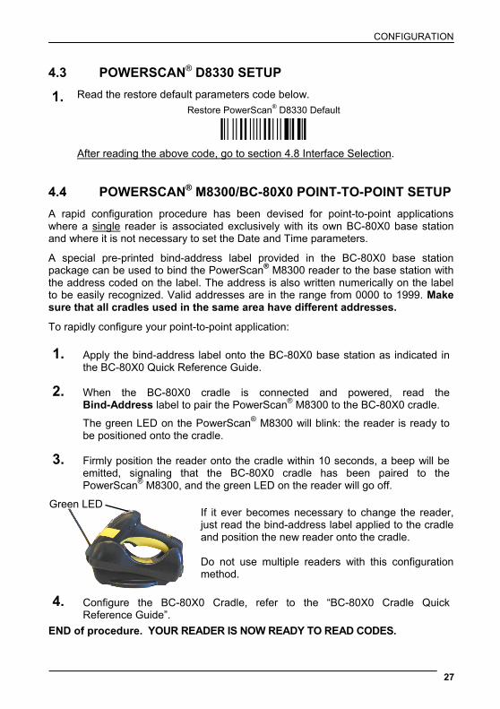
3. Firmly position the reader onto the cradle within 10 seconds, a beep will be emitted, signaling that the BC-80X0 cradle has been paired to the PowerScan® M8300, and the green LED on the reader will go off.
If it ever becomes necessary to change the reader, just read the bind-address label applied to the cradle and position the new reader onto the cradle. Do not use multiple readers with this configuration method.
4. Configure the BC-80X0 Cradle, refer to the “BC-80X0 Cradle Quick Reference Guide”.
END of procedure. YOUR READER IS NOW READY TO READ CODES.
Green LED
POWERSCAN® D8330/M8300
28
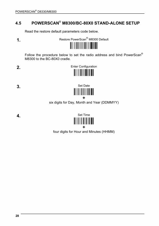
4.5 POWERSCAN® M8300/BC-80X0 STAND-ALONE SETUP Read the restore default parameters code below.
Restore PowerScan® M8300 Default 1.
Ì$+$*oÎ Follow the procedure below to set the radio address and bind PowerScan®
M8300 to the BC-80X0 cradle.
Enter Configuration 2. Ì$+;Î
Set Date 3.
ÌIA%Î
+
six digits for Day, Month and Year (DDMMYY)
Set Time 4.
ÌIB'Î
+
four digits for Hour and Minutes (HHMM)
CONFIGURATION
29
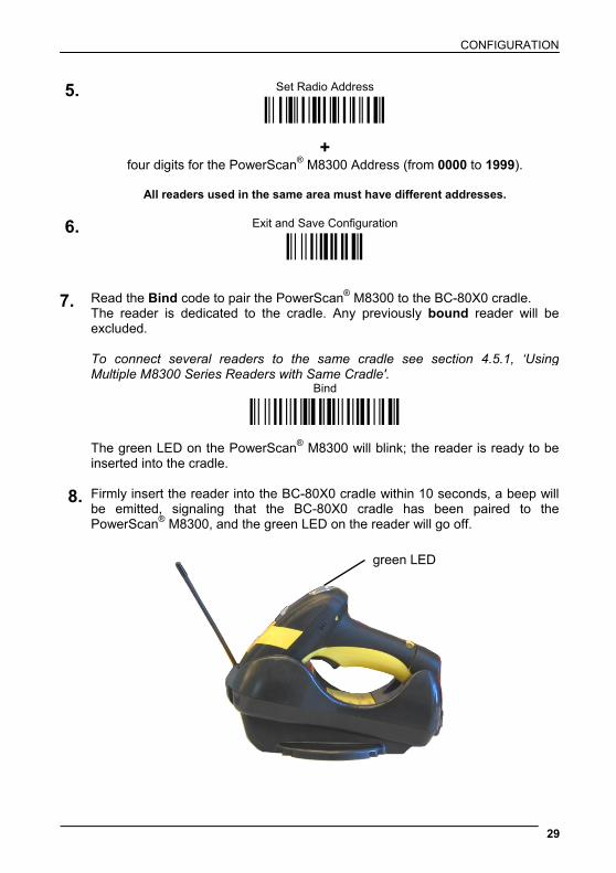
Set Radio Address 5.
ÌRA0RFHÎ
+
four digits for the PowerScan® M8300 Address (from 0000 to 1999).
All readers used in the same area must have different addresses.
Exit and Save Configuration 6. Ì$-?Î
7. Read the Bind code to pair the PowerScan® M8300 to the BC-80X0 cradle. The reader is dedicated to the cradle. Any previously bound reader will be excluded. To connect several readers to the same cradle see section 4.5.1, ‘Using Multiple M8300 Series Readers with Same Cradle'.
Bind Ì$+RN0$-IÎ
The green LED on the PowerScan® M8300 will blink; the reader is ready to be
inserted into the cradle. 8. Firmly insert the reader into the BC-80X0 cradle within 10 seconds, a beep will
be emitted, signaling that the BC-80X0 cradle has been paired to the PowerScan® M8300, and the green LED on the reader will go off.
green LED

POWERSCAN® D8330/M8300
30
Read the BC-80X0 restore default code:
9. Restore BC-80X0 Default
Ì$+RX0$-qÎ
Go to section 4.8 Interface Selection. 4.5.1 Using Multiple M-Series Readers with Same Cradle If you want to use several M-Series readers with the same BC-80X0 cradle, you must first Bind the cradle with one of the readers (see previously described configuration procedure).
Successive readers can be associated with the same cradle by following the configuration procedure substituting the Bind command with Join (step 7). 7. Join
Ì$+RN1$-NÎ
The green LED on the PowerScan® M8300 will blink: the reader is ready to be positioned onto the cradle. Complete step 8.
END of procedure.
CAUTION
All readers associated with the same cradle must have different addresses.
YOUR READER IS NOW READY TO READ BAR CODES. To change the defaults see section 4.10.

CONFIGURATION
31
4.5.2 PowerScan® M8300/STAR-Modem™ in Stand-Alone Mode To configure a PowerScan® M8300 reader to communicate with STAR-Modem™ in Stand-alone Mode, follow the procedure in section 4.5 substituting steps 6 and 7 with those below:
STAR-Modem™ Address 6. ÌRSRÎ
Read the code above and the four-digit address of the STAR-Modem™.
7. Exit and Save configuration Ì$-?Î
END of procedure.
YOUR READER IS NOW READY TO READ BAR CODES. To change the defaults see section 4.10.
POWERSCAN® D8330/M8300
32
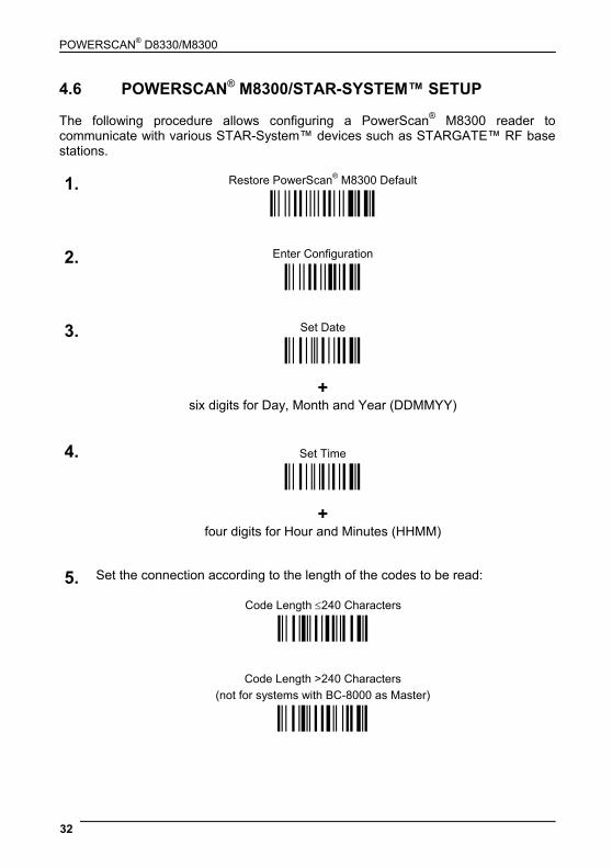
4.6 POWERSCAN® M8300/STAR-SYSTEM™ SETUP The following procedure allows configuring a PowerScan® M8300 reader to communicate with various STAR-System™ devices such as STARGATE™ RF base stations.
Restore PowerScan® M8300 Default 1. Ì$+$*oÎ
Enter Configuration 2. Ì$+;Î
Set Date 3.
ÌIA%Î
+
six digits for Day, Month and Year (DDMMYY)
Set Time 4.
ÌIB'Î
+
four digits for Hour and Minutes (HHMM)
Set the connection according to the length of the codes to be read: 5.
Code Length ≤240 Characters
ÌRA1aÎ
Code Length >240 Characters
(not for systems with BC-8000 as Master) ÌRA2dÎ

CONFIGURATION
33
Set Radio Address
6. ÌRF8Î +
four digits from the Numeric Table in the range 0000-1999.
All readers must have different addresses.
First STAR-System™ Address
7. ÌRSRÎ Read the code above and the four-digit address of the First STAR-System™
device in the system.
Set Last STAR-System™ Address
8. ÌRTTÎ Read the code above and the four-digit address of the Last STAR-System™
device in the system.
NOTE
Whenever the system is composed of a single base station, the first and last base station addresses (steps 7 and 8) must have the same value.
Exit and Save Configuration
9. Ì$-?Î
END of procedure. YOUR READER IS NOW READY TO READ BAR CODES. To change the defaults see section 4.10.
POWERSCAN® D8330/M8300
34
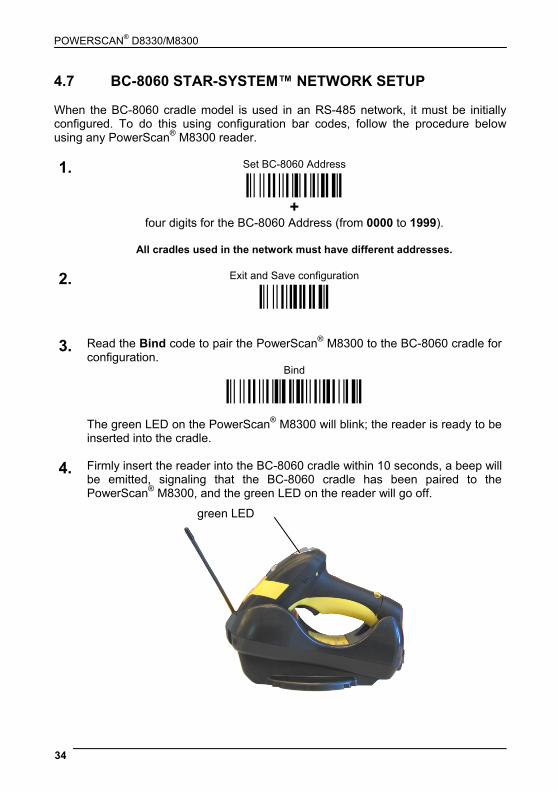
4.7 BC-8060 STAR-SYSTEM™ NETWORK SETUP When the BC-8060 cradle model is used in an RS-485 network, it must be initially configured. To do this using configuration bar codes, follow the procedure below using any PowerScan® M8300 reader.
Set BC-8060 Address 1. Ì$+RF4Î
+
four digits for the BC-8060 Address (from 0000 to 1999).
All cradles used in the network must have different addresses.
Exit and Save configuration 2. Ì$-?Î
3. Read the Bind code to pair the PowerScan® M8300 to the BC-8060 cradle for
configuration. Bind Ì$+RN0$-IÎ
The green LED on the PowerScan® M8300 will blink; the reader is ready to be
inserted into the cradle.
4. Firmly insert the reader into the BC-8060 cradle within 10 seconds, a beep will be emitted, signaling that the BC-8060 cradle has been paired to the PowerScan® M8300, and the green LED on the reader will go off.
green LED
CONFIGURATION
35
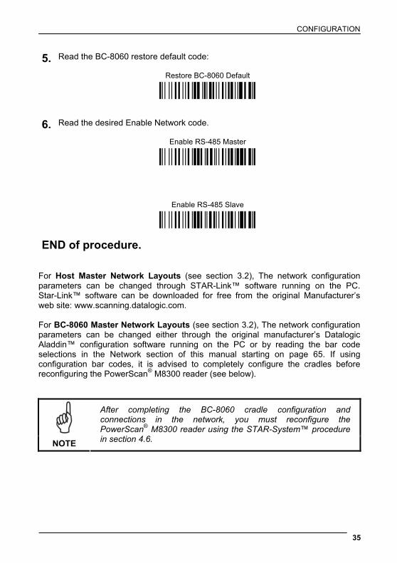
Read the BC-8060 restore default code:
5. Restore BC-8060 Default
Ì$+RX0$-qÎ
Read the desired Enable Network code.
Enable RS-485 Master
6.
Ì$+RZ2$-ÇÎ
Enable RS-485 Slave
Ì$+RZ1$-~Î
END of procedure. For Host Master Network Layouts (see section 3.2), The network configuration parameters can be changed through STAR-Link™ software running on the PC. Star-Link™ software can be downloaded for free from the original Manufacturer’s web site: www.scanning.datalogic.com. For BC-8060 Master Network Layouts (see section 3.2), The network configuration parameters can be changed either through the original manufacturer’s Datalogic Aladdin™ configuration software running on the PC or by reading the bar code selections in the Network section of this manual starting on page 65. If using configuration bar codes, it is advised to completely configure the cradles before reconfiguring the PowerScan® M8300 reader (see below).
NOTE
After completing the BC-8060 cradle configuration and connections in the network, you must reconfigure the PowerScan® M8300 reader using the STAR-System™ procedure in section 4.6.
POWERSCAN® D8330/M8300
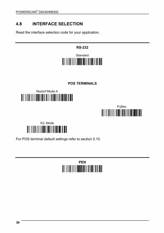
36
4.8 INTERFACE SELECTION Read the interface selection code for your application.
RS-232
Standard
Ì$+CP0$-$Î
POS TERMINALS
Nixdorf Mode A
Ì$+CM2EC0$->Î
Fujitsu
ICL Mode
Ì$+CM1$-ÈÎ
Ì$+CM0$-ÃÎ
For POS terminal default settings refer to section 5.15.
PEN
Ì$+CP6$-BÎ
CONFIGURATION
37
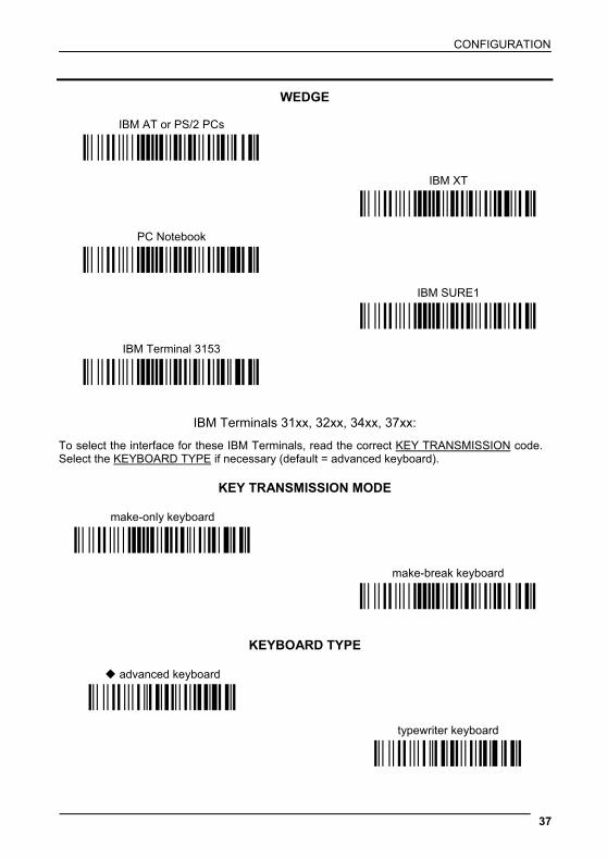
WEDGE
IBM AT or PS/2 PCs
Ì$+CP500$-aÎ
IBM XT
PC Notebook
Ì$+CP503$-vÎ
Ì$+CP505$-ÈÎ
IBM SURE1
IBM Terminal 3153
Ì$+CP506$-$Î
Ì$+CP504$-}Î
IBM Terminals 31xx, 32xx, 34xx, 37xx:
To select the interface for these IBM Terminals, read the correct KEY TRANSMISSION code. Select the KEYBOARD TYPE if necessary (default = advanced keyboard).
KEY TRANSMISSION MODE
make-only keyboard
Ì$+CP502$-oÎ
make-break keyboard
Ì$+CP501$-hÎ
KEYBOARD TYPE
advanced keyboard
Ì$+FK1$-ÉÎ
typewriter keyboard Ì$+FK0$-ÄÎ
POWERSCAN® D8330/M8300
38
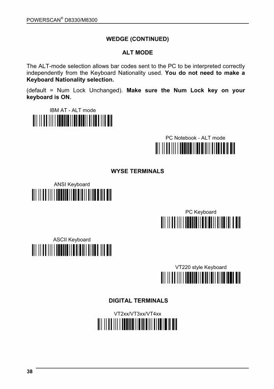
WEDGE (CONTINUED)
ALT MODE
The ALT-mode selection allows bar codes sent to the PC to be interpreted correctly independently from the Keyboard Nationality used. You do not need to make a Keyboard Nationality selection.
(default = Num Lock Unchanged). Make sure the Num Lock key on your keyboard is ON.
IBM AT - ALT mode
Ì$+CP507$-+Î
PC Notebook - ALT mode Ì$+CP508$-2Î
WYSE TERMINALS
ANSI Keyboard
Ì$+CP509$-9Î
PC Keyboard
ASCII Keyboard
Ì$+CP510$-gÎ
Ì$+CP511$-nÎ
VT220 style Keyboard Ì$+CP514$-ÇÎ
DIGITAL TERMINALS
VT2xx/VT3xx/VT4xx
Ì$+CP512$-uÎ
CONFIGURATION
39
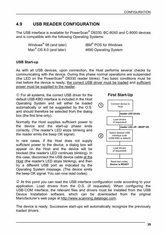
4.9 USB READER CONFIGURATION The USB interface is available for PowerScan® D8330, BC-80X0 and C-8000 devices and is compatible with the following Operating Systems:
Windows® 98 (and later) IBM® POS for Windows Mac® OS 8.0 (and later) 4690 Operating System
USB Start-up As with all USB devices, upon connection, the Host performs several checks by communicating with the device. During this phase normal operations are suspended (the LED on the PowerScan® D8330 reader blinks). Two basic conditions must be met before the device is ready, the correct USB driver must be loaded and sufficient power must be supplied to the reader.
For all systems, the correct USB driver for the default USB-KBD interface is included in the Host Operating System and will either be loaded automatically or will be suggested by the O.S. and should therefore be selected from the dialog box (the first time only).
Normally the Host supplies sufficient power to the device and the start-up phase ends correctly. (The reader's LED stops blinking and the reader emits the beep OK signal).
In rare cases, if the Host does not supply sufficient power to the device, a dialog box will appear on the Host and the device will be blocked (the reader's LED continues blinking). In this case, disconnect the USB device cable at the Host (the reader's LED stops blinking), and then try a different USB port as indicated by the Operating System message. (The device emits the beep OK signal. You can now read codes).
At this point you can read the USB interface configuration code according to your application. Load drivers from the O.S. (if requested). When configuring the USB-COM interface, the relevant files and drivers must be installed from the USB Device Installation software, which can be downloaded from the original Manufacturer’s web page at http://www.scanning.datalogic.com. The device is ready. Successive start-ups will automatically recognize the previously loaded drivers.
Connect device to Host
Select desired USB interface code
(USB-KBD is default)
Read test codes.Device is READY
Load drivers (if requested)
Load drivers (if requested)
reader LED blinks
reader LED off - BEEP OK
First Start-Up
1
2
POWERSCAN® D8330/M8300
40
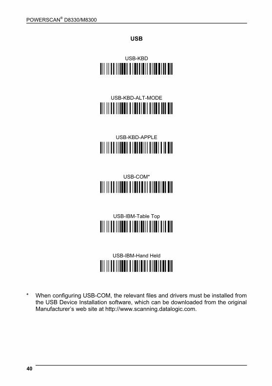
USB
USB-KBD
Ì$+UA03$-:Î
USB-KBD-ALT-MODE
Ì$+UA04$-@Î
USB-KBD-APPLE
Ì$+UA05$-FÎ
USB-COM*
Ì$+UA02$-4Î
USB-IBM-Table Top
Ì$+UA00$-(Î
USB-IBM-Hand Held
Ì$+UA01$-.Î
* When configuring USB-COM, the relevant files and drivers must be installed from the USB Device Installation software, which can be downloaded from the original Manufacturer’s web site at http://www.scanning.datalogic.com.
CONFIGURATION
41
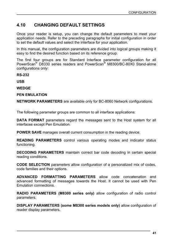
4.10 CHANGING DEFAULT SETTINGS Once your reader is setup, you can change the default parameters to meet your application needs. Refer to the preceding paragraphs for initial configuration in order to set the default values and select the interface for your application.
In this manual, the configuration parameters are divided into logical groups making it easy to find the desired function based on its reference group.
The first four groups are for Standard Interface parameter configuration for all PowerScan® D8330 series readers and PowerScan® M8300/BC-80X0 Stand-alone configurations only:
RS-232
USB
WEDGE
PEN EMULATION
NETWORK PARAMETERS are available only for BC-8060 Network configurations.
The following parameter groups are common to all interface applications:
DATA FORMAT parameters regard the messages sent to the Host system for all interfaces except Pen Emulation.
POWER SAVE manages overall current consumption in the reading device.
READING PARAMETERS control various operating modes and indicator status functioning.
DECODING PARAMETERS maintain correct bar code decoding in certain special reading conditions.
CODE SELECTION parameters allow configuration of a personalized mix of codes, code families and their options.
ADVANCED FORMATTING PARAMETERS allow code concatenation and advanced formatting of messages towards the Host. It cannot be used with Pen Emulation connections.
RADIO PARAMETERS (M8300 series only) allow configuration of radio control parameters.
DISPLAY PARAMETERS (some M8300 series models only) allow configuration of reader display parameters.
42
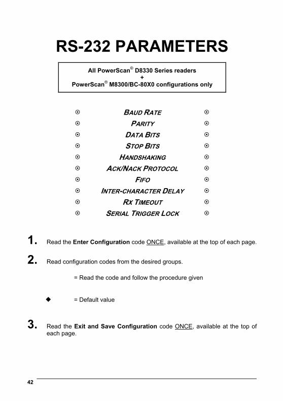
RS-232 PARAMETERS
All PowerScan® D8330 Series readers +
PowerScan® M8300/BC-80X0 configurations only
BAUD RATE
PARITY
DATA BITS
STOP BITS
HANDSHAKING
ACK/NACK PROTOCOL
FIFO
INTER-CHARACTER DELAY
RX TIMEOUT
SERIAL TRIGGER LOCK
1. Read the Enter Configuration code ONCE, available at the top of each page.
2. Read configuration codes from the desired groups.
= Read the code and follow the procedure given
= Default value
3. Read the Exit and Save Configuration code ONCE, available at the top of each page.

Enter Configuration Exit and Save Configuration
Ì$+;Î RS-232 Ì$-?Î
43
BAUD RATE
300 baud
ÌCD1XÎ
600 baud
1200 baud
ÌCD2[Î
ÌCD3^Î
2400 baud
4800 baud
ÌCD4aÎ
ÌCD5dÎ
9600 baud
19200 baud
ÌCD6gÎ
ÌCD7jÎ
38400 baud
ÌCD8mÎ
PARITY
none
ÌCC0SÎ
even parity
odd parity
ÌCC1VÎ
ÌCC2YÎ

Enter Configuration Exit and Save Configuration
Ì$+;Î RS-232 Ì$-?Î
44
DATA BITS
7 bits
ÌCA0OÎ
8 bits
9 bits
ÌCA1RÎ
ÌCA2UÎ
STOP BITS
1 stop bit
ÌCB0QÎ
2 stop bits
ÌCB1TÎ
HANDSHAKING
disable
ÌCE0WÎ
hardware (RTS/CTS)
software (XON/XOFF)
ÌCE1ZÎ
ÌCE2]Î
RTS always ON ÌCE3`Î
See section 5.1.1 for details.

Enter Configuration Exit and Save Configuration
Ì$+;Î RS-232 Ì$-?Î
45
ACK/NACK PROTOCOL
disable
ÌER0sÎ
enable
ÌER1vÎ
See section 5.1.2 for details, particularly on implementing this parameter with PowerScan®
M8300.
FIFO
disable
ÌEC0UÎ
enable
ÌEC1XÎ
See section 5.1.3 for details.
INTER-CHARACTER DELAY
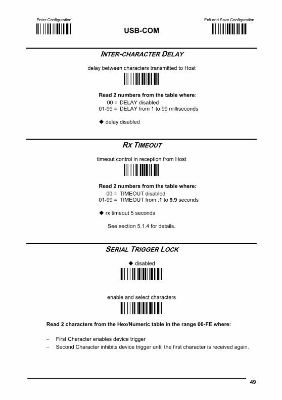
delay between characters transmitted to Host
ÌCK3Î
Read 2 numbers from the table where: 00 = DELAY disabled 01-99 = DELAY from 1 to 99 milliseconds
delay disabled
Enter Configuration Exit and Save Configuration
Ì$+;Î RS-232 Ì$-?Î
46
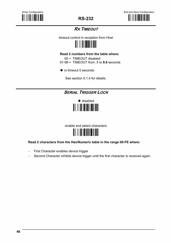
RX TIMEOUT
timeout control in reception from Host
ÌCL5Î
Read 2 numbers from the table where: 00 = TIMEOUT disabled 01-99 = TIMEOUT from .1 to 9.9 seconds
rx timeout 5 seconds
See section 5.1.4 for details.
SERIAL TRIGGER LOCK
disabled
ÌCR0qÎ
enable and select characters
ÌCR1tÎ
Read 2 characters from the Hex/Numeric table in the range 00-FE where:
− First Character enables device trigger − Second Character inhibits device trigger until the first character is received again.
47
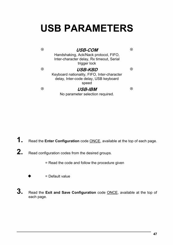
USB PARAMETERS
USB-COM Handshaking, Ack/Nack protocol, FIFO, Inter-character delay, Rx timeout, Serial
trigger lock
USB-KBD Keyboard nationality, FIFO, Inter-character
delay, Inter-code delay, USB keyboard speed
USB-IBM No parameter selection required.
1. Read the Enter Configuration code ONCE, available at the top of each page.
2. Read configuration codes from the desired groups.
= Read the code and follow the procedure given
= Default value
3. Read the Exit and Save Configuration code ONCE, available at the top of each page.
Enter Configuration Exit and Save Configuration
Ì$+;Î USB-COM Ì$-?Î
48
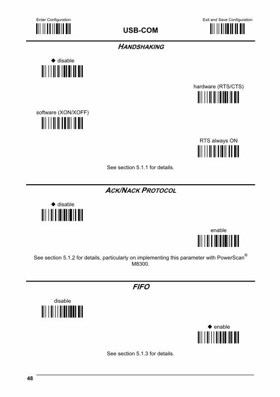
HANDSHAKING
disable
ÌCE0WÎ
hardware (RTS/CTS)
software (XON/XOFF)
ÌCE1ZÎ
ÌCE2]Î
RTS always ON ÌCE3`Î
See section 5.1.1 for details.
ACK/NACK PROTOCOL
disable
ÌER0sÎ
enable
ÌER1vÎ
See section 5.1.2 for details, particularly on implementing this parameter with PowerScan®
M8300.
FIFO
disable
ÌEC0UÎ
enable
ÌEC1XÎ
See section 5.1.3 for details.
Enter Configuration Exit and Save Configuration
Ì$+;Î USB-COM Ì$-?Î
49
INTER-CHARACTER DELAY
delay between characters transmitted to Host
ÌCK3Î
Read 2 numbers from the table where: 00 = DELAY disabled 01-99 = DELAY from 1 to 99 milliseconds
delay disabled
RX TIMEOUT
timeout control in reception from Host
ÌCL5Î
Read 2 numbers from the table where: 00 = TIMEOUT disabled 01-99 = TIMEOUT from .1 to 9.9 seconds
rx timeout 5 seconds
See section 5.1.4 for details.
SERIAL TRIGGER LOCK
disabled
ÌCR0qÎ
enable and select characters
ÌCR1tÎ
Read 2 characters from the Hex/Numeric table in the range 00-FE where:
− First Character enables device trigger − Second Character inhibits device trigger until the first character is received again.

Enter Configuration Exit and Save Configuration
Ì$+;Î USB-KBD Ì$-?Î
50
KEYBOARD NATIONALITY
Not Available for USB-KBD-ALT-MODE Interface This parameter default value is restored through the Interface Selection code and not Restore Default.
Belgian
ÌFJ7yÎ
English (UK)
French
ÌFJ4pÎ
ÌFJ2jÎ
German
Italian
ÌFJ3mÎ
ÌFJ1gÎ
Spanish
Swedish
ÌFJ6vÎ
ÌFJ5sÎ
USA ÌFJ0dÎ
Enter Configuration Exit and Save Configuration
Ì$+;Î USB-KBD Ì$-?Î
51
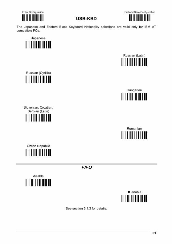
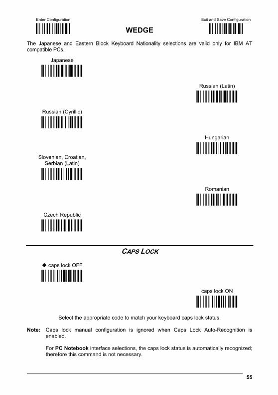
The Japanese and Eastern Block Keyboard Nationality selections are valid only for IBM AT compatible PCs.
Japanese
ÌFJ8|Î
Russian (Latin)
Russian (Cyrillic)
ÌFJ9ÃÎ
ÌFJA0Î
Hungarian
Slovenian, Croatian, Serbian (Latin)
ÌFJB3Î
ÌFJC6Î
Romanian
Czech Republic
ÌFJD9Î
ÌFJE<Î
FIFO
disable
ÌEC0UÎ
enable
ÌEC1XÎ
See section 5.1.3 for details.

Enter Configuration Exit and Save Configuration
Ì$+;Î USB-KBD Ì$-?Î
52
INTER-CHARACTER DELAY
delay between characters transmitted to Host
ÌCK3Î
Read 2 numbers from the table where: 00 = DELAY disabled 01-99 = DELAY from 1 to 99 milliseconds
delay disabled
INTER-CODE DELAY
delay between codes transmitted to Host
ÌFG.Î
Read 2 numbers from the table where: 00 = DELAY disabled 01-99 = DELAY from 1 to 99 seconds
delay disabled
USB KEYBOARD SPEED
Normal
ÌUT10cÎ
Fast
ÌUT01dÎ
53
WEDGE PARAMETERS
All PowerScan® D8330 Series readers +
PowerScan® M8300/BC-80X0 configurations only
KEYBOARD NATIONALITY
CAPS LOCK
CAPS LOCK AUTO-RECOGNITION
NUM LOCK
INTER-CHARACTER DELAY
INTER-CODE DELAY
KEYBOARD SETTING
WEDGE CONTROL CHARACTER EMULATION
1. Read the Enter Configuration code ONCE, available at the top of each page.
2. Read configuration codes from the desired groups.
= Read the code and follow the procedure given
= Default value
3. Read the Exit and Save Configuration code ONCE, available at the top of each page.
Enter Configuration Exit and Save Configuration
Ì$+;Î WEDGE Ì$-?Î
54
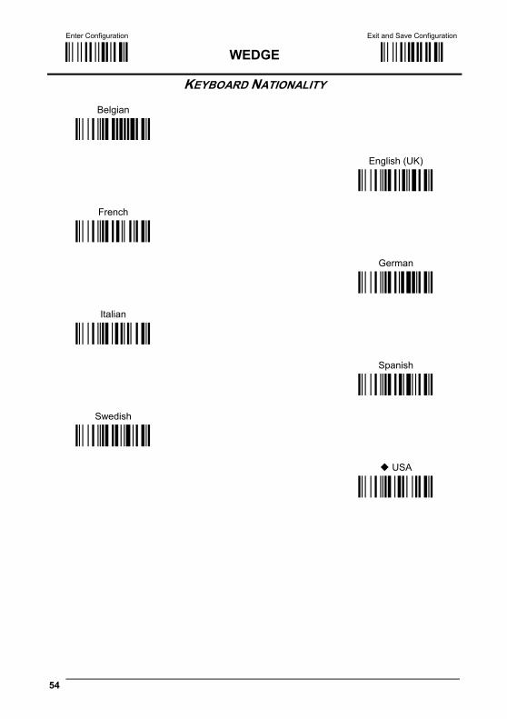
KEYBOARD NATIONALITY
Belgian
ÌFJ7yÎ
English (UK)
French
ÌFJ4pÎ
ÌFJ2jÎ
German
Italian
ÌFJ3mÎ
ÌFJ1gÎ
Spanish
Swedish
ÌFJ6vÎ
ÌFJ5sÎ
USA ÌFJ0dÎ
Enter Configuration Exit and Save Configuration
Ì$+;Î WEDGE Ì$-?Î
55
The Japanese and Eastern Block Keyboard Nationality selections are valid only for IBM AT compatible PCs.
Japanese
ÌFJ8|Î
Russian (Latin)
Russian (Cyrillic)
ÌFJ9ÃÎ
ÌFJA0Î
Hungarian
Slovenian, Croatian, Serbian (Latin)
ÌFJB3Î
ÌFJC6Î
Romanian
Czech Republic
ÌFJD9Î
ÌFJE<Î
CAPS LOCK
caps lock OFF
ÌFE0ZÎ
caps lock ON
ÌFE1]Î
Select the appropriate code to match your keyboard caps lock status.
Note: Caps lock manual configuration is ignored when Caps Lock Auto-Recognition is
enabled.
For PC Notebook interface selections, the caps lock status is automatically recognized; therefore this command is not necessary.

Enter Configuration Exit and Save Configuration
Ì$+;Î WEDGE Ì$-?Î
56
CAPS LOCK AUTO-RECOGNITION (IBM AT COMPATIBLE ONLY)
disable
ÌFP0pÎ
enable
ÌFP1sÎ
NUM LOCK
toggle num lock
ÌFL1kÎ
num lock unchanged
ÌFL0hÎ
This selection is used together with the Alt Mode interface selection for AT or Notebook PCs. It changes the way the Alt Mode procedure is executed; therefore it should be set as follows: • if your keyboard Num Lock is normally on use num lock unchanged • if your keyboard Num Lock is normally off use toggle num lock
In this way the device will execute the Alt Mode procedure correctly for your application.
INTER-CHARACTER DELAY
delay between characters transmitted to Host
ÌCK3Î
Read 2 numbers from the table where: 00 = DELAY disabled 01-99 = DELAY from 1 to 99 milliseconds
delay disabled
Enter Configuration Exit and Save Configuration
Ì$+;Î WEDGE Ì$-?Î
57
INTER-CODE DELAY
delay between codes transmitted to Host
ÌFG.Î
Read 2 numbers from the table where: 00 = DELAY disabled 01-99 = DELAY from 1 to 99 seconds
delay disabled
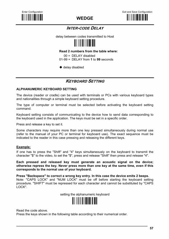
KEYBOARD SETTING ALPHANUMERIC KEYBOARD SETTING
The device (reader or cradle) can be used with terminals or PCs with various keyboard types and nationalities through a simple keyboard setting procedure.
The type of computer or terminal must be selected before activating the keyboard setting command.
Keyboard setting consists of communicating to the device how to send data corresponding to the keyboard used in the application. The keys must be set in a specific order.
Press and release a key to set it.
Some characters may require more than one key pressed simultaneously during normal use (refer to the manual of your PC or terminal for keyboard use). The exact sequence must be indicated to the reader in this case pressing and releasing the different keys. Example: If one has to press the "Shift" and "4" keys simultaneously on the keyboard to transmit the character "$" to the video, to set the "$", press and release "Shift" then press and release "4". Each pressed and released key must generate an acoustic signal on the device; otherwise repress the key. Never press more than one key at the same time, even if this corresponds to the normal use of your keyboard. Press "Backspace" to correct a wrong key entry. In this case the device emits 2 beeps. Note: "CAPS LOCK" and "NUM LOCK" must be off before starting the keyboard setting procedure. "SHIFT" must be repressed for each character and cannot be substituted by "CAPS LOCK".
setting the alphanumeric keyboard
ÌFB0TÎ Read the code above. Press the keys shown in the following table according to their numerical order.
WEDGE
58
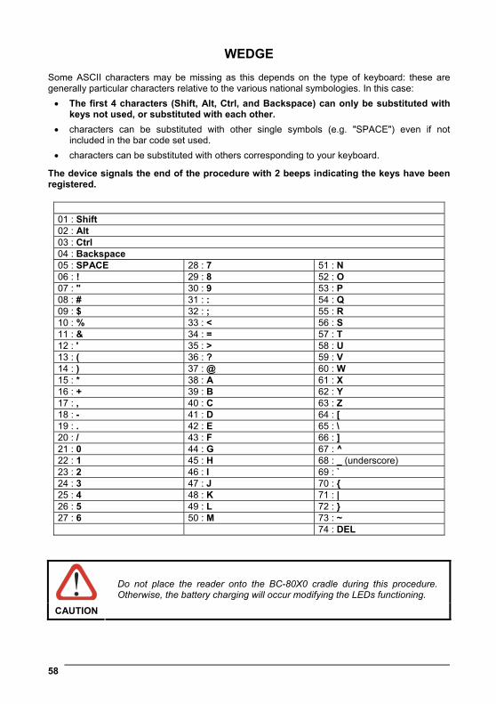
Some ASCII characters may be missing as this depends on the type of keyboard: these are generally particular characters relative to the various national symbologies. In this case: • The first 4 characters (Shift, Alt, Ctrl, and Backspace) can only be substituted with
keys not used, or substituted with each other. • characters can be substituted with other single symbols (e.g. "SPACE") even if not
included in the bar code set used. • characters can be substituted with others corresponding to your keyboard.
The device signals the end of the procedure with 2 beeps indicating the keys have been registered.
01 : Shift 02 : Alt 03 : Ctrl 04 : Backspace 05 : SPACE 28 : 7 51 : N 06 : ! 29 : 8 52 : O 07 : " 30 : 9 53 : P 08 : # 31 : : 54 : Q 09 : $ 32 : ; 55 : R 10 : % 33 : < 56 : S 11 : & 34 : = 57 : T 12 : ' 35 : > 58 : U 13 : ( 36 : ? 59 : V 14 : ) 37 : @ 60 : W 15 : * 38 : A 61 : X 16 : + 39 : B 62 : Y 17 : , 40 : C 63 : Z 18 : - 41 : D 64 : [ 19 : . 42 : E 65 : \ 20 : / 43 : F 66 : ] 21 : 0 44 : G 67 : ^ 22 : 1 45 : H 68 : _ (underscore) 23 : 2 46 : I 69 : ` 24 : 3 47 : J 70 : { 25 : 4 48 : K 71 : | 26 : 5 49 : L 72 : } 27 : 6 50 : M 73 : ~ 74 : DEL
CAUTION
Do not place the reader onto the BC-80X0 cradle during this procedure. Otherwise, the battery charging will occur modifying the LEDs functioning.

Enter Configuration Exit and Save Configuration
Ì$+;Î WEDGE Ì$-?Î
59
CONTROL CHARACTER EMULATION
Ctrl + Shift + Key
ÌFO0nÎ
Ctrl + Key
ÌFO1qÎ
60
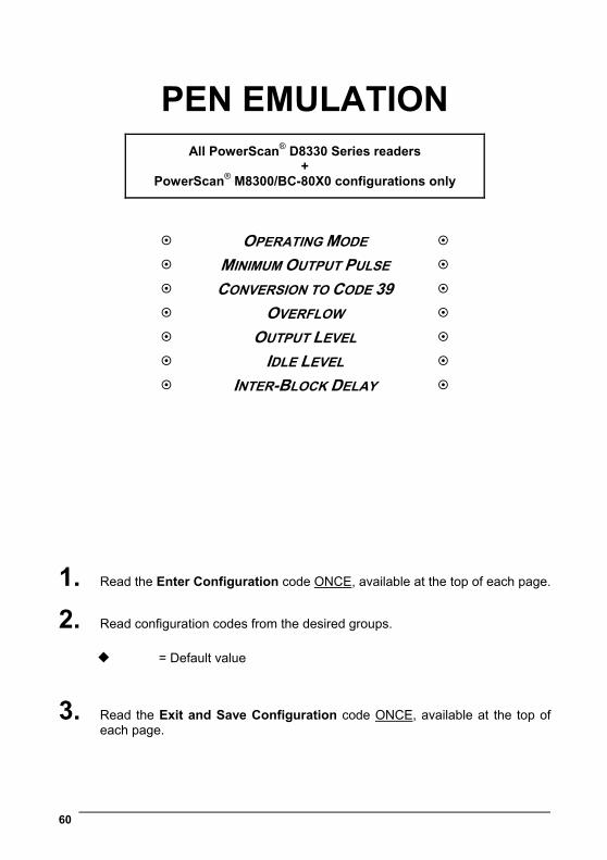
PEN EMULATION
All PowerScan® D8330 Series readers +
PowerScan® M8300/BC-80X0 configurations only
OPERATING MODE
MINIMUM OUTPUT PULSE
CONVERSION TO CODE 39
OVERFLOW
OUTPUT LEVEL
IDLE LEVEL
INTER-BLOCK DELAY
1. Read the Enter Configuration code ONCE, available at the top of each page.
2. Read configuration codes from the desired groups.
= Default value
3. Read the Exit and Save Configuration code ONCE, available at the top of each page.

PEN EMULATION
61
The operating mode parameters are complete commands and do not require reading the Enter and Exit configuration codes.
OPERATING MODE
interpret mode
Ì$]8Î Interprets commands without sending them to the decoder.
transparent mode
Ì$[4Î
Sends commands to the decoder without interpreting them.
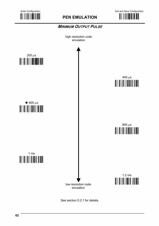
Enter Configuration Exit and Save Configuration
Ì$+;Î PEN EMULATION Ì$-?Î
62
MINIMUM OUTPUT PULSE
200 μs
ÌDG0\Î
400 μs
600 μs
ÌDG1_Î
ÌDG2bÎ
800 μs
1 ms
ÌDG3eÎ
ÌDG4hÎ
1.2 ms
low resolution code emulation
high resolution codeemulation
ÌDG5kÎ
See section 5.2.1 for details.
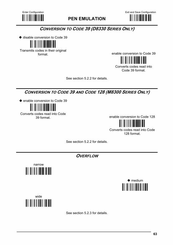
Enter Configuration Exit and Save Configuration
Ì$+;Î PEN EMULATION Ì$-?Î
63
CONVERSION TO CODE 39 (D8330 SERIES ONLY)
disable conversion to Code 39
ÌDA0PÎ Transmits codes in their original
format.
enable conversion to Code 39
ÌDA1SÎ
Converts codes read into
Code 39 format.
See section 5.2.2 for details.
CONVERSION TO CODE 39 AND CODE 128 (M8300 SERIES ONLY)
enable conversion to Code 39
ÌDA1SÎ Converts codes read into Code
39 format.
enable conversion to Code 128
ÌDA0PÎ
Converts codes read into Code
128 format.
See section 5.2.2 for details.
OVERFLOW
narrow
ÌDH0^Î
medium
wide
ÌDH1aÎ
ÌDH2dÎ
See section 5.2.3 for details.
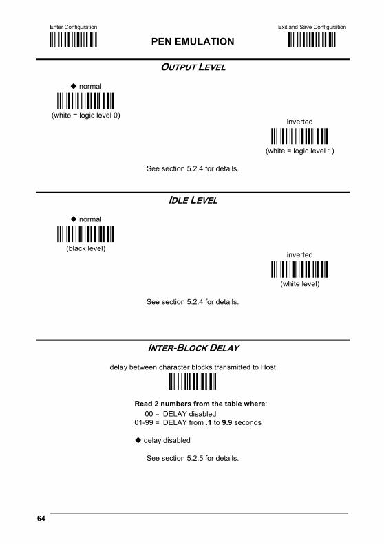
Enter Configuration Exit and Save Configuration
Ì$+;Î PEN EMULATION Ì$-?Î
64
OUTPUT LEVEL
normal
ÌDD0VÎ (white = logic level 0)
inverted
ÌDD1YÎ (white = logic level 1)
See section 5.2.4 for details.
IDLE LEVEL
normal
ÌDE0XÎ (black level)
inverted
ÌDE1[Î (white level)
See section 5.2.4 for details.
INTER-BLOCK DELAY
delay between character blocks transmitted to Host
ÌCK3Î
Read 2 numbers from the table where: 00 = DELAY disabled 01-99 = DELAY from .1 to 9.9 seconds
delay disabled
See section 5.2.5 for details.
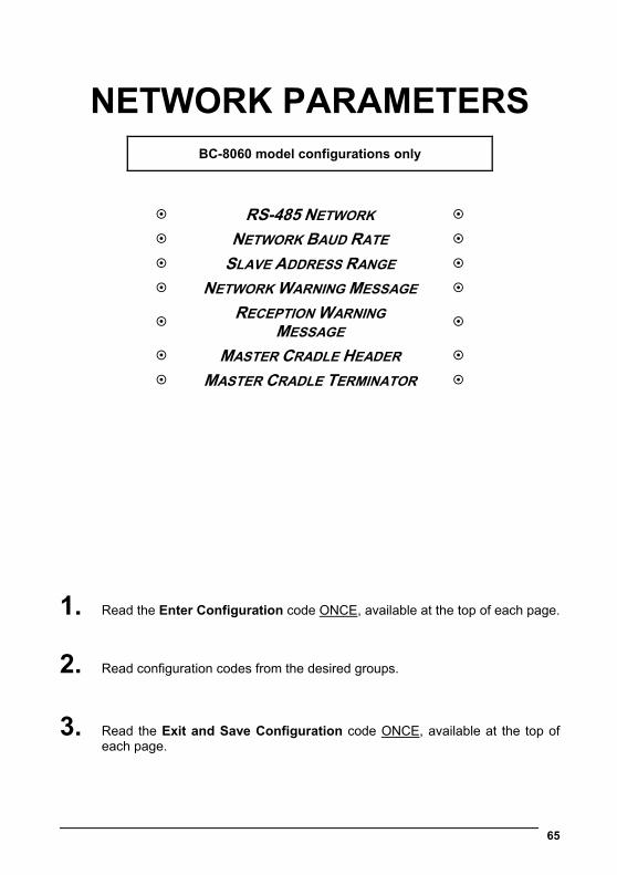
65
NETWORK PARAMETERS
BC-8060 model configurations only
RS-485 NETWORK
NETWORK BAUD RATE
SLAVE ADDRESS RANGE
NETWORK WARNING MESSAGE
RECEPTION WARNING MESSAGE
MASTER CRADLE HEADER
MASTER CRADLE TERMINATOR
1. Read the Enter Configuration code ONCE, available at the top of each page.
2. Read configuration codes from the desired groups.
3. Read the Exit and Save Configuration code ONCE, available at the top of each page.
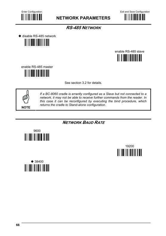
Enter Configuration Exit and Save Configuration
Ì$+;Î NETWORK PARAMETERS Ì$-?Î
66
RS-485 NETWORK
disable RS-485 network
ÌRZ0)Î
enable RS-485 slave
enable RS-485 master
ÌRZ1,Î
ÌRZ2/Î
See section 3.2 for details.
NOTE
If a BC-8060 cradle is errantly configured as a Slave but not connected to a network, it may not be able to receive further commands from the reader. In this case it can be reconfigured by executing the bind procedure, which returns the cradle to Stand-alone configuration.
NETWORK BAUD RATE
9600
ÌJE0^Î
19200
38400
ÌJE1aÎ
ÌJE2dÎ
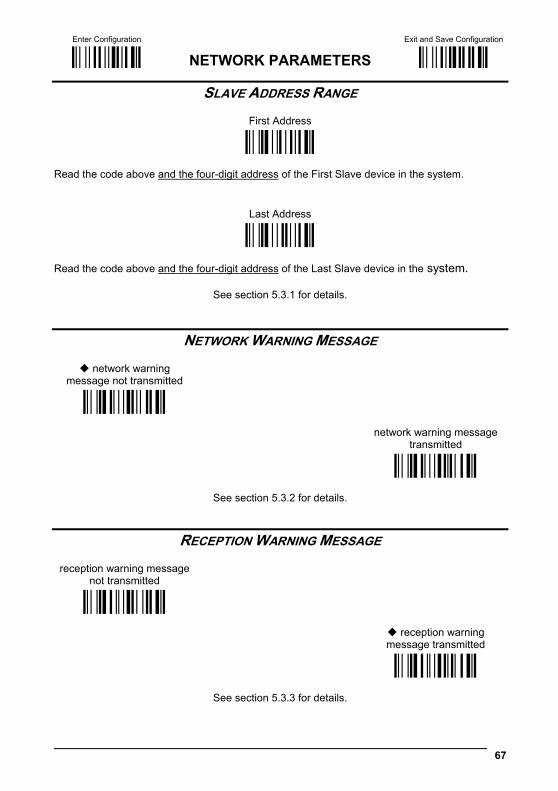
Enter Configuration Exit and Save Configuration
Ì$+;Î NETWORK PARAMETERS Ì$-?Î
67
SLAVE ADDRESS RANGE
First Address
ÌJB(Î Read the code above and the four-digit address of the First Slave device in the system.
Last Address
ÌJC*Î Read the code above and the four-digit address of the Last Slave device in the system.
See section 5.3.1 for details.
NETWORK WARNING MESSAGE
network warning message not transmitted
ÌJG0bÎ
network warning message
transmitted
ÌJG1eÎ
See section 5.3.2 for details.
RECEPTION WARNING MESSAGE reception warning message
not transmitted
ÌJH0dÎ
reception warning message transmitted
ÌJH1gÎ
See section 5.3.3 for details.
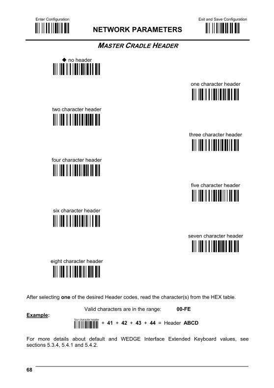
Enter Configuration Exit and Save Configuration
Ì$+;Î NETWORK PARAMETERS Ì$-?Î
68
MASTER CRADLE HEADER no header ÌJA00/Î
one character header
two character header
ÌJA013Î
ÌJA027Î
three character header
four character header
ÌJA03;Î
ÌJA04?Î
five character header
six character header
ÌJA05CÎ
ÌJA06GÎ
seven character header
eight character header
ÌJA07KÎ
ÌJA08OÎ
After selecting one of the desired Header codes, read the character(s) from the HEX table.
Valid characters are in the range: 00-FE Example:
four character header+ 41 + 42 + 43 + 44 = Header ABCD
For more details about default and WEDGE Interface Extended Keyboard values, see sections 5.3.4, 5.4.1 and 5.4.2.

Enter Configuration Exit and Save Configuration
Ì$+;Î NETWORK PARAMETERS Ì$-?Î
69
MASTER CRADLE TERMINATOR no terminator ÌJA102Î
one character terminator
two character terminator
ÌJA116Î
ÌJA12:Î
three character terminator
four character terminator
ÌJA13>Î
ÌJA14BÎ
five character terminator
six character terminator
ÌJA15FÎ
ÌJA16JÎ
seven character terminator
eight character terminator
ÌJA17NÎ
ÌJA18RÎ
After selecting one of the desired Terminator codes, read the character(s) from the HEX table.
Valid characters are in the range: 00-FE Example:
two character terminator+ 0D + 0A = Terminator CR LF
For more details about default and WEDGE Interface Extended Keyboard values, see sections 5.3.4, 5.4.1 and 5.4.2.
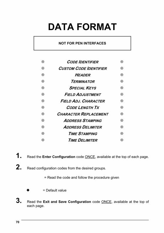
70
DATA FORMAT
NOT FOR PEN INTERFACES
CODE IDENTIFIER
CUSTOM CODE IDENTIFIER
HEADER
TERMINATOR
SPECIAL KEYS
FIELD ADJUSTMENT
FIELD ADJ. CHARACTER
CODE LENGTH TX
CHARACTER REPLACEMENT
ADDRESS STAMPING
ADDRESS DELIMITER
TIME STAMPING
TIME DELIMITER
1. Read the Enter Configuration code ONCE, available at the top of each page.
2. Read configuration codes from the desired groups.
= Read the code and follow the procedure given
= Default value
3. Read the Exit and Save Configuration code ONCE, available at the top of each page.
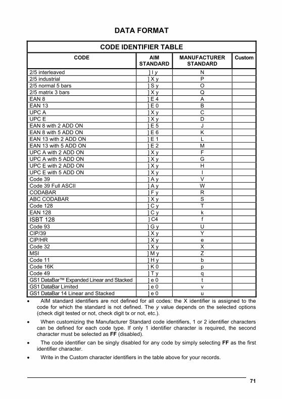
DATA FORMAT
71
CODE IDENTIFIER TABLE CODE AIM
STANDARD MANUFACTURER
STANDARD Custom
2/5 interleaved ] I y N 2/5 industrial ] X y P 2/5 normal 5 bars ] S y O 2/5 matrix 3 bars ] X y Q EAN 8 ] E 4 A EAN 13 ] E 0 B UPC A ] X y C UPC E ] X y D EAN 8 with 2 ADD ON ] E 5 J EAN 8 with 5 ADD ON ] E 6 K EAN 13 with 2 ADD ON ] E 1 L EAN 13 with 5 ADD ON ] E 2 M UPC A with 2 ADD ON ] X y F UPC A with 5 ADD ON ] X y G UPC E with 2 ADD ON ] X y H UPC E with 5 ADD ON ] X y I Code 39 ] A y V Code 39 Full ASCII ] A y W CODABAR ] F y R ABC CODABAR ] X y S Code 128 ] C y T EAN 128 ] C y k ISBT 128 ] C4 f Code 93 ] G y U CIP/39 ] X y Y CIP/HR ] X y e Code 32 ] X y X MSI ] M y Z Code 11 ] H y b Code 16K ] K 0 p Code 49 ] T y q GS1 DataBar™ Expanded Linear and Stacked ] e 0 t GS1 DataBar Limited ] e 0 v GS1 DataBar 14 Linear and Stacked ] e 0 u • AIM standard identifiers are not defined for all codes: the X identifier is assigned to the
code for which the standard is not defined. The y value depends on the selected options (check digit tested or not, check digit tx or not, etc.).
• When customizing the Manufacturer Standard code identifiers, 1 or 2 identifier characters can be defined for each code type. If only 1 identifier character is required, the second character must be selected as FF (disabled).
• The code identifier can be singly disabled for any code by simply selecting FF as the first identifier character.
• Write in the Custom character identifiers in the table above for your records.
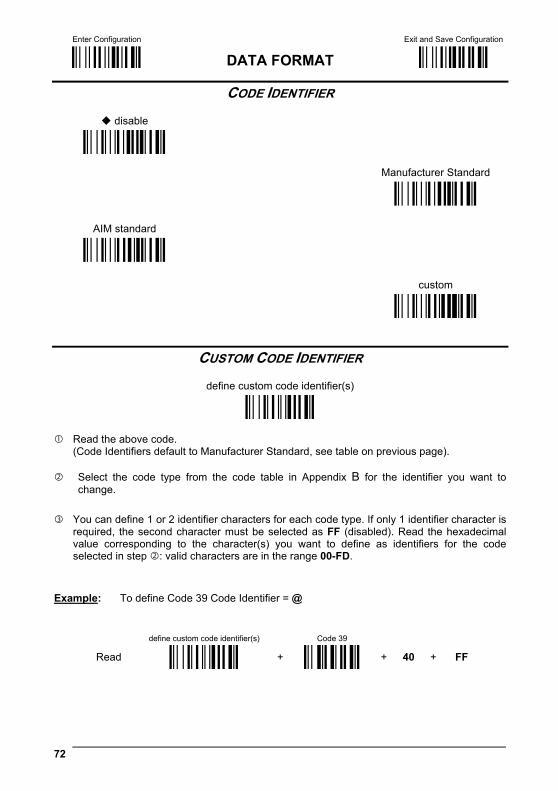
Enter Configuration Exit and Save Configuration
Ì$+;Î DATA FORMAT Ì$-?Î
72
CODE IDENTIFIER
disable
ÌEB0SÎ
Manufacturer Standard
AIM standard
ÌEB1VÎ
ÌEB2YÎ
custom
ÌEB3\Î
CUSTOM CODE IDENTIFIER
define custom code identifier(s)
ÌEH/Î
Read the above code. (Code Identifiers default to Manufacturer Standard, see table on previous page).
Select the code type from the code table in Appendix B for the identifier you want to
change.
You can define 1 or 2 identifier characters for each code type. If only 1 identifier character is required, the second character must be selected as FF (disabled). Read the hexadecimal value corresponding to the character(s) you want to define as identifiers for the code selected in step : valid characters are in the range 00-FD.
Example: To define Code 39 Code Identifier = @
define custom code identifier(s) Code 39
Read ÌEH/Î + ÌVWÎ + 40 + FF

Enter Configuration Exit and Save Configuration
Ì$+;Î DATA FORMAT Ì$-?Î
73
HEADER no header ÌEA00*Î
one character header
two character header
ÌEA01.Î
ÌEA022Î
three character header
four character header
ÌEA036Î
ÌEA04:Î
five character header
six character header
ÌEA05>Î
ÌEA06BÎ
seven character header
eight character header
ÌEA07FÎ
ÌEA08JÎ
After selecting one of the desired Header codes, read the character(s) from the HEX table. Valid characters are in the range 00-FE. For Wedge and USB-KBD interfaces, it is also possible to read the Special Key(s) on page 75. Example:
four character header
+ 41 + 42 + 43 + 44 = Header ABCD
For more details see sections 5.4.1 and 5.4.2.

Enter Configuration Exit and Save Configuration
Ì$+;Î DATA FORMAT Ì$-?Î
74
TERMINATOR no terminator
ÌEA10-Î
one character terminator
two character terminator
ÌEA111Î
ÌEA125Î
three character terminator
four character terminator
ÌEA139Î
ÌEA14=Î
five character terminator
six character terminator
ÌEA15AÎ
ÌEA16EÎ
seven character terminator
eight character terminator
ÌEA17IÎ
ÌEA18MÎ
After selecting one of the desired Header codes, read the character(s) from the HEX table. Valid characters are in the range 00-FE. For Wedge and USB-KBD interfaces, it is also possible to read the Special Key(s) on page 75. Example:
two character terminator
+ 0D + 0A = Terminator CR LF
For more details see sections 5.4.1 and 5.4.2.
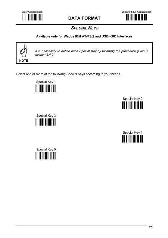
Enter Configuration Exit and Save Configuration
Ì$+;Î DATA FORMAT Ì$-?Î
75
SPECIAL KEYS
Available only for Wedge IBM AT-PS/2 and USB-KBD Interfaces
NOTE
It is necessary to define each Special Key by following the procedure given in section 5.4.2.
Select one or more of the following Special Keys according to your needs. Special Key 1
Ì9CÄÎ
Special Key 2
Special Key 3
Ì9DÆÎ
Ì9EÈÎ
Special Key 4
Special Key 5
Ì9FÊÎ
ÌA0bÎ
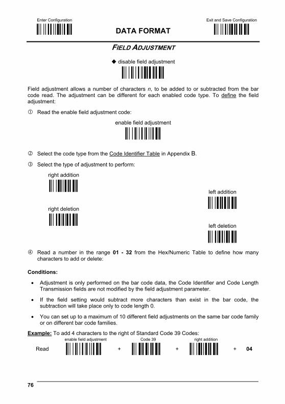
Enter Configuration Exit and Save Configuration
Ì$+;Î DATA FORMAT Ì$-?Î
76
FIELD ADJUSTMENT
disable field adjustment
ÌEF0[Î Field adjustment allows a number of characters n, to be added to or subtracted from the bar code read. The adjustment can be different for each enabled code type. To define the field adjustment:
Read the enable field adjustment code:
enable field adjustment
ÌEF+Î
Select the code type from the Code Identifier Table in Appendix B.
Select the type of adjustment to perform:
right addition
Ì01Î
left addition
right deletion Ì12Î
Ì23Î
left deletion
Ì34Î
Read a number in the range 01 - 32 from the Hex/Numeric Table to define how many characters to add or delete:
Conditions:
• Adjustment is only performed on the bar code data, the Code Identifier and Code Length Transmission fields are not modified by the field adjustment parameter.
• If the field setting would subtract more characters than exist in the bar code, the subtraction will take place only to code length 0.
• You can set up to a maximum of 10 different field adjustments on the same bar code family or on different bar code families.
Example: To add 4 characters to the right of Standard Code 39 Codes: enable field adjustment Code 39 right addition
Read ÌEF+Î + ÌVWÎ + Ì01Î + 04

Enter Configuration Exit and Save Configuration
Ì$+;Î DATA FORMAT Ì$-?Î
77
FIELD ADJUSTMENT CHARACTER
Read the field adjustment character code:
field adjustment character
ÌEG-Î
Read the hexadecimal value corresponding to the character you want to use for field
adjustment. Valid characters are in the range 00-FE. For Wedge and USB-KBD interfaces, it is also possible to read the Special Key(s) on page 75.
Example:
To define the field adjustment character = A:
Read
field adjustment character
+ 41
CODE LENGTH TX
code length not transmitted
ÌEE0YÎ
code length transmitted in variable-digit format
ÌEE1\Î
code length transmitted in fixed 4-digit format
ÌEE2_Î The code length is transmitted in the message after the Headers and Code Identifier characters. The code length is calculated after performing any field adjustment operations.
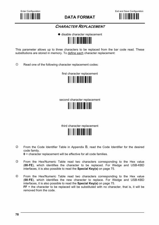
Enter Configuration Exit and Save Configuration
Ì$+;Î DATA FORMAT Ì$-?Î
78
CHARACTER REPLACEMENT
disable character replacement
ÌEO0mÎ This parameter allows up to three characters to be replaced from the bar code read. These substitutions are stored in memory. To define each character replacement:
Read one of the following character replacement codes:
first character replacement
ÌEO1pÎ
second character replacement
ÌEO2sÎ
third character replacement
ÌEO3vÎ
From the Code Identifier Table in Appendix B, read the Code Identifier for the desired
code family. 0 = character replacement will be effective for all code families.
From the Hex/Numeric Table read two characters corresponding to the Hex value
(00-FE), which identifies the character to be replaced. For Wedge and USB-KBD interfaces, it is also possible to read the Special Key(s) on page 75.
From the Hex/Numeric Table read two characters corresponding to the Hex value
(00-FE), which identifies the new character to replace. For Wedge and USB-KBD interfaces, it is also possible to read the Special Key(s) on page 75. FF = the character to be replaced will be substituted with no character, that is, it will be removed from the code.
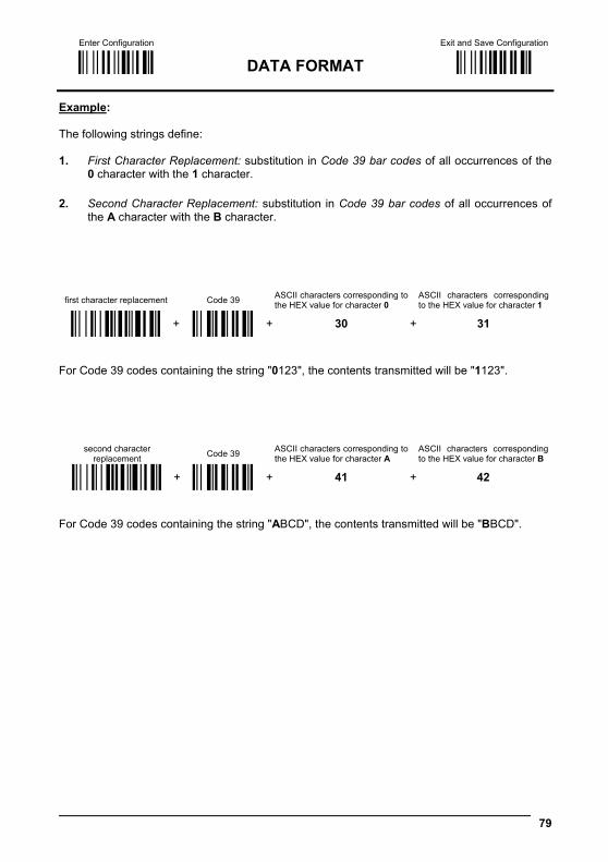
Enter Configuration Exit and Save Configuration
Ì$+;Î DATA FORMAT Ì$-?Î
79
Example: The following strings define: 1. First Character Replacement: substitution in Code 39 bar codes of all occurrences of the
0 character with the 1 character. 2. Second Character Replacement: substitution in Code 39 bar codes of all occurrences of
the A character with the B character.
first character replacement Code 39 ASCII characters corresponding to the HEX value for character 0
ASCII characters corresponding to the HEX value for character 1
ÌEO1pÎ + ÌVWÎ + 30 + 31
For Code 39 codes containing the string "0123", the contents transmitted will be "1123".
second character replacement Code 39 ASCII characters corresponding to
the HEX value for character A ASCII characters corresponding to the HEX value for character B
ÌEO2sÎ + ÌVWÎ + 41 + 42 For Code 39 codes containing the string "ABCD", the contents transmitted will be "BBCD".
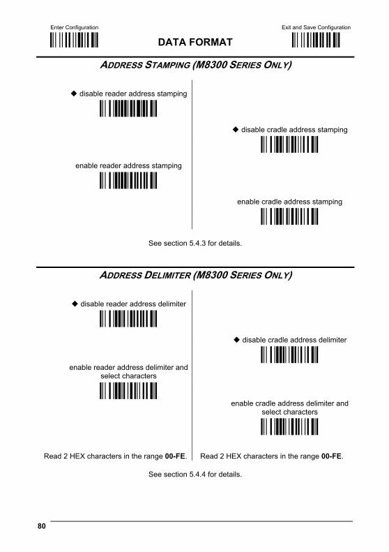
Enter Configuration Exit and Save Configuration
Ì$+;Î DATA FORMAT Ì$-?Î
80
ADDRESS STAMPING (M8300 SERIES ONLY)
disable reader address stamping
ÌRU0ÊÎ
disable cradle address stamping
enable reader address stamping
ÌRW0#Î
ÌRU1"Î
enable cradle address stamping
ÌRW1&Î
See section 5.4.3 for details.
ADDRESS DELIMITER (M8300 SERIES ONLY)
disable reader address delimiter
ÌRV0!Î
disable cradle address delimiter
enable reader address delimiter and
select characters
ÌRY0'Î
ÌRV1$Î enable cradle address delimiter and
select characters
ÌRY1*Î
Read 2 HEX characters in the range 00-FE. Read 2 HEX characters in the range 00-FE.
See section 5.4.4 for details.
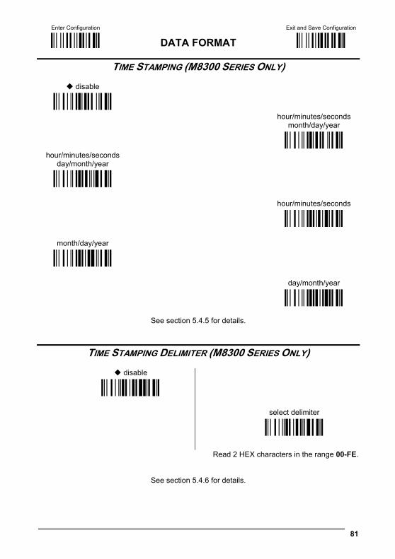
Enter Configuration Exit and Save Configuration
Ì$+;Î DATA FORMAT Ì$-?Î
81
TIME STAMPING (M8300 SERIES ONLY)
disable
ÌIL0kÎ
hour/minutes/seconds month/day/year
hour/minutes/seconds day/month/year
ÌIL1nÎ
ÌIL2qÎ
hour/minutes/seconds
month/day/year
ÌIL3tÎ
ÌIL4wÎ
day/month/year
ÌIL5zÎ
See section 5.4.5 for details.
TIME STAMPING DELIMITER (M8300 SERIES ONLY)
disable ÌIM0mÎ
select delimiter
ÌIM1pÎ
Read 2 HEX characters in the range 00-FE.
See section 5.4.6 for details.
82
POWER SAVE
SLEEP STATE
ENTER SLEEP TIMEOUT
1. Read the Enter Configuration code ONCE, available at the top of each page.
2. Read configuration codes from the desired groups.
= Read the code and follow the procedure given
= Default value
3. Read the Exit and Save Configuration code ONCE, available at the top of each page.
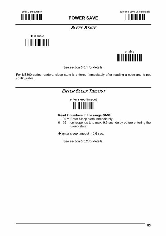
Enter Configuration Exit and Save Configuration
Ì$+;Î POWER SAVE Ì$-?Î
83
SLEEP STATE
disable
ÌBQ0nÎ
enable
ÌBQ1qÎ
See section 5.5.1 for details.
For M8300 series readers, sleep state is entered immediately after reading a code and is not configurable.
ENTER SLEEP TIMEOUT
enter sleep timeout
ÌBR@Î
Read 2 numbers in the range 00-99: 00 = Enter Sleep state immediately 01-99 = corresponds to a max. 9.9 sec. delay before entering the
Sleep state.
enter sleep timeout = 0.6 sec.
See section 5.5.2 for details.
84
READING PARAMETERS
TRIGGER TYPE
TRIGGER SIGNAL
TRIGGER CLICK
TRIGGER-OFF TIMEOUT
FLASH MODE
READS PER CYCLE
SAFETY TIME
BEEPER INTENSITY
BEEPER TONE
BEEPER TYPE
BEEPER LENGTH
GOOD READ SPOT DURATION
AIMING SYSTEM
CRADLE BEEPER INTENSITY
1. Read the Enter Configuration code ONCE, available at the top of each page.
2. Read configuration codes from the desired groups.
= Read the code and follow the procedure given
= Default value
3. Read the Exit and Save Configuration code ONCE, available at the top of each page.
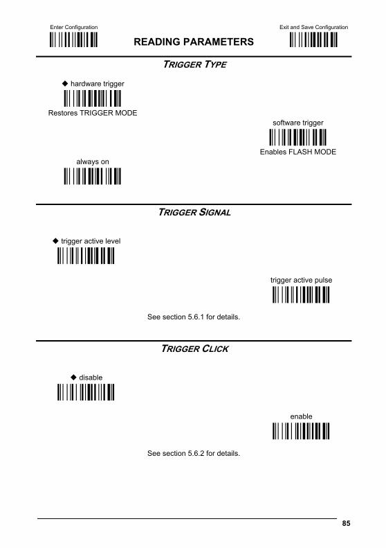
Enter Configuration Exit and Save Configuration
Ì$+;Î READING PARAMETERS Ì$-?Î
85
TRIGGER TYPE
hardware trigger
ÌBK1eÎ Restores TRIGGER MODE
software trigger
always on
ÌBK0bÎ Enables FLASH MODE
ÌBK3kÎ
TRIGGER SIGNAL
trigger active level
ÌBA0NÎ
trigger active pulse
ÌBA1QÎ
See section 5.6.1 for details.
TRIGGER CLICK
disable
ÌBc0+Î
enable
ÌBc1.Î
See section 5.6.2 for details.
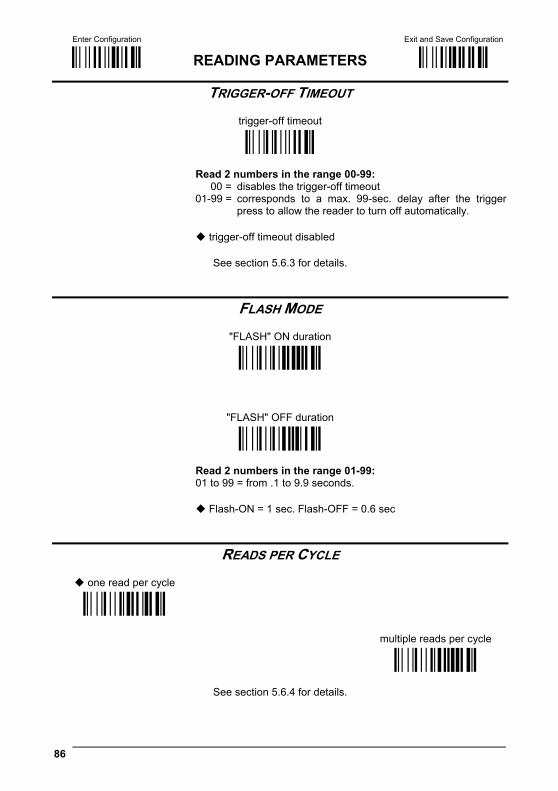
Enter Configuration Exit and Save Configuration
Ì$+;Î READING PARAMETERS Ì$-?Î
86
TRIGGER-OFF TIMEOUT
trigger-off timeout
ÌBD$Î
Read 2 numbers in the range 00-99: 00 = disables the trigger-off timeout 01-99 = corresponds to a max. 99-sec. delay after the trigger
press to allow the reader to turn off automatically.
trigger-off timeout disabled
See section 5.6.3 for details.
FLASH MODE
"FLASH" ON duration
ÌBB0PÎ
"FLASH" OFF duration
ÌBB1SÎ
Read 2 numbers in the range 01-99: 01 to 99 = from .1 to 9.9 seconds.
Flash-ON = 1 sec. Flash-OFF = 0.6 sec
READS PER CYCLE
one read per cycle
ÌBC0RÎ
multiple reads per cycle
ÌBC1UÎ
See section 5.6.4 for details.
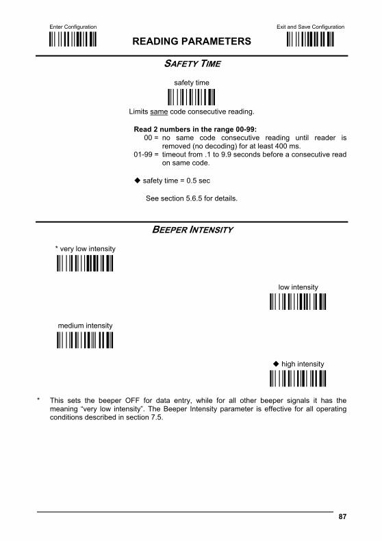
Enter Configuration Exit and Save Configuration
Ì$+;Î READING PARAMETERS Ì$-?Î
87
SAFETY TIME
safety time
ÌBE&Î
Limits same code consecutive reading.
Read 2 numbers in the range 00-99: 00 = no same code consecutive reading until reader is
removed (no decoding) for at least 400 ms. 01-99 = timeout from .1 to 9.9 seconds before a consecutive read
on same code.
safety time = 0.5 sec
See section 5.6.5 for details.
BEEPER INTENSITY
* very low intensity
ÌBG0ZÎ
low intensity
medium intensity
ÌBG1]Î
ÌBG2`Î
high intensity
ÌBG3cÎ
* This sets the beeper OFF for data entry, while for all other beeper signals it has the
meaning “very low intensity”. The Beeper Intensity parameter is effective for all operating conditions described in section 7.5.

Enter Configuration Exit and Save Configuration
Ì$+;Î READING PARAMETERS Ì$-?Î
88
BEEPER TONE
tone 1
ÌBH0\Î
tone 2
tone 3
ÌBH1_Î
ÌBH2bÎ
tone 4 ÌBH3eÎ
BEEPER TYPE
monotone
ÌBJ0`Î
bitonal
ÌBJ1cÎ
BEEPER LENGTH
long
ÌBI0^Î
short
ÌBI1aÎ

Enter Configuration Exit and Save Configuration
Ì$+;Î READING PARAMETERS Ì$-?Î
89
GOOD READ SPOT DURATION
disable
ÌBV0xÎ
short
medium
ÌBV1{Î
ÌBV2~Î
long ÌBV3ÅÎ
AIMING SYSTEM
disabled
ÌBj09Î
enabled
ÌBj1<Î
CRADLE BEEPER INTENSITY
disable
ÌJI0fÎ
low intensity
medium intensity
ÌJI1iÎ
ÌJI2lÎ
high intensity ÌJI3oÎ
90
DECODING PARAMETERS
INK SPREAD
OVERFLOW CONTROL
INTERDIGIT CONTROL
DECODING SAFETY
PUZZLE SOLVER™
CAUTION
Before changing these parameter values read the descriptions in section 5.7.
1. Read the Enter Configuration code ONCE, available at the top of each page.
2. Read configuration codes from the desired groups. = Default value
3. Read the Exit and Save Configuration code ONCE, available at the top of each page.
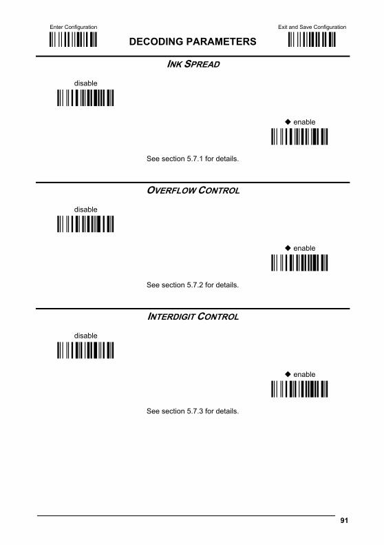
Enter Configuration Exit and Save Configuration
Ì$+;Î DECODING PARAMETERS Ì$-?Î
91
INK SPREAD
disable
ÌAX0{Î
enable
ÌAX1~Î
See section 5.7.1 for details.
OVERFLOW CONTROL
disable
ÌAW1|Î
enable
ÌAW0yÎ
See section 5.7.2 for details.
INTERDIGIT CONTROL
disable
ÌAV0wÎ
enable
ÌAV1zÎ
See section 5.7.3 for details.
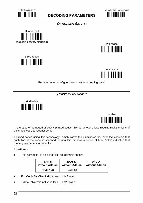
Enter Configuration Exit and Save Configuration
Ì$+;Î DECODING PARAMETERS Ì$-?Î
92
DECODING SAFETY
one read
ÌED0WÎ
(decoding safety disabled)
two reads
three reads
ÌED1ZÎ
ÌED2]Î
four reads
ÌED3`Î
Required number of good reads before accepting code.
PUZZLE SOLVER™
disable
ÌAU0uÎ
enable
ÌAU1xÎ
In the case of damaged or poorly printed codes, this parameter allows reading multiple parts of the single code to reconstruct it. To read codes using this technology, simply move the illuminated bar over the code so that each line of the code is scanned. During this process a series of brief “ticks” indicates that reading is proceeding correctly. Conditions:
• This parameter is only valid for the following codes:
EAN 8 without Add-on
EAN 13 without Add-on
UPC A without Add-on
Code 128 Code 39
• For Code 39, Check digit control is forced.
• PuzzleSolver™ is not valid for ISBT 128 code.
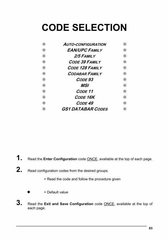
93
CODE SELECTION
AUTO-CONFIGURATION EAN/UPC FAMILY 2/5 FAMILY CODE 39 FAMILY CODE 128 FAMILY CODABAR FAMILY CODE 93 MSI CODE 11 CODE 16K CODE 49 GS1 DATABAR CODES
1. Read the Enter Configuration code ONCE, available at the top of each page.
2. Read configuration codes from the desired groups.
= Read the code and follow the procedure given
= Default value
3. Read the Exit and Save Configuration code ONCE, available at the top of each page.
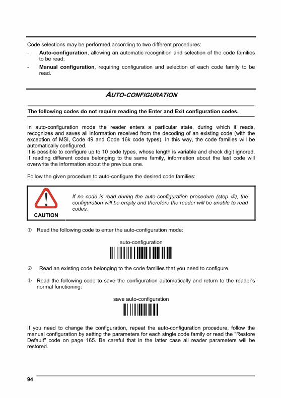
94
Code selections may be performed according to two different procedures: - Auto-configuration, allowing an automatic recognition and selection of the code families
to be read; - Manual configuration, requiring configuration and selection of each code family to be
read.
AUTO-CONFIGURATION The following codes do not require reading the Enter and Exit configuration codes.
In auto-configuration mode the reader enters a particular state, during which it reads, recognizes and saves all information received from the decoding of an existing code (with the exception of MSI, Code 49 and Code 16k code types). In this way, the code families will be automatically configured. It is possible to configure up to 10 code types, whose length is variable and check digit ignored. If reading different codes belonging to the same family, information about the last code will overwrite the information about the previous one. Follow the given procedure to auto-configure the desired code families:
CAUTION
If no code is read during the auto-configuration procedure (step ), the configuration will be empty and therefore the reader will be unable to read codes.
Read the following code to enter the auto-configuration mode:
auto-configuration
Ì#+AUTOWÎ
Read an existing code belonging to the code families that you need to configure.
Read the following code to save the configuration automatically and return to the reader's normal functioning:
save auto-configuration
Ì$-?Î If you need to change the configuration, repeat the auto-configuration procedure, follow the manual configuration by setting the parameters for each single code family or read the "Restore Default" code on page 165. Be careful that in the latter case all reader parameters will be restored.
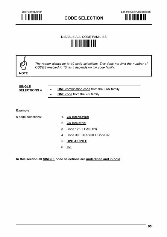
Enter Configuration Exit and Save Configuration
Ì$+;Î CODE SELECTION Ì$-?Î
95
DISABLE ALL CODE FAMILIES
ÌAZ0ÃÎ
NOTE
The reader allows up to 10 code selections. This does not limit the number of CODES enabled to 10, as it depends on the code family.
SINGLE SELECTIONS =
Example
5 code selections: 1. 2/5 Interleaved
2. 2/5 Industrial
3. Code 128 + EAN 128
4. Code 39 Full ASCII + Code 32
5. UPC A/UPC E
6. etc. In this section all SINGLE code selections are underlined and in bold.
• ONE combination code from the EAN family • ONE code from the 2/5 family

Enter Configuration Exit and Save Configuration
Ì$+;Î CODE SELECTION Ì$-?Î
96
EAN/UPC FAMILY
disable the family
ÌAA0MÎ
Read the desired family code Note: Since the EAN/UPC without ADD ON code selection is enabled by default, to correctly enable another selection, first disable the family.
EAN 8/EAN 13/UPC A/UPC E with and without ADD ON
ÌAA8eÎ
WITHOUT ADD ON
EAN 8/EAN 13/UPC A/UPC E
ÌAA1PÎ
EAN 8/EAN 13
UPC A/UPC E
ÌAA3VÎ
ÌAA4YÎ
WITH ADD ON 2 AND 5
EAN 8/EAN 13/UPC A/UPC E
ÌAA5\Î
EAN 8/EAN 13
UPC A/UPC E
ÌAA6_Î
ÌAA7bÎ
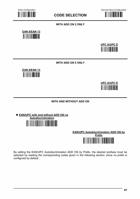
Enter Configuration Exit and Save Configuration
Ì$+;Î CODE SELECTION Ì$-?Î
97
WITH ADD ON 2 ONLY
EAN 8/EAN 13 ÌAAK7Î
UPC A/UPC E
ÌAAM=Î
WITH ADD ON 5 ONLY
EAN 8/EAN 13 ÌAAL:Î
UPC A/UPC E
ÌAAN@Î
WITH AND WITHOUT ADD ON
EAN/UPC with and without ADD ON no Autodiscrimination
ÌAA8Ad03Î EAN/UPC Autodiscrimination ADD ON by
Prefix ÌAA8Ad19Î
By setting the EAN/UPC Autodiscrimination ADD ON by Prefix, the desired prefixes must be selected by reading the corresponding codes given in the following section, since no prefix is configured by default.
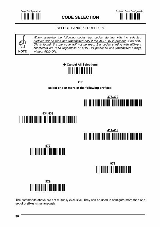
Enter Configuration Exit and Save Configuration
Ì$+;Î CODE SELECTION Ì$-?Î
98
SELECT EAN/UPC PREFIXES
NOTE
When scanning the following codes, bar codes starting with the selected prefixes will be read and transmitted only if the ADD ON is present. If no ADD ON is found, the bar code will not be read. Bar codes starting with different characters are read regardless of ADD ON presence and transmitted always without ADD ON.
Cancel All Selections
ÌET0wÎ
OR
select one or more of the following prefixes: 378/379
ÌET1378ET2379PÎ
434/439
ÌET3434ET4439ÉÎ
414/419
ÌET5414ET6419}Î 977
ÌET7977QÎ
978
ÌET8978ZÎ
979
ÌET9979cÎ The commands above are not mutually exclusive. They can be used to configure more than one set of prefixes simultaneously.
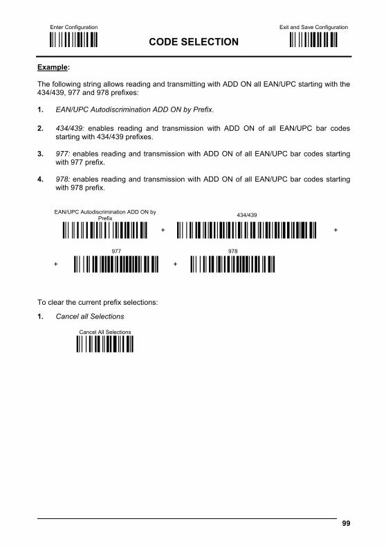
Enter Configuration Exit and Save Configuration
Ì$+;Î CODE SELECTION Ì$-?Î
99
Example: The following string allows reading and transmitting with ADD ON all EAN/UPC starting with the 434/439, 977 and 978 prefixes: 1. EAN/UPC Autodiscrimination ADD ON by Prefix. 2. 434/439: enables reading and transmission with ADD ON of all EAN/UPC bar codes
starting with 434/439 prefixes. 3. 977: enables reading and transmission with ADD ON of all EAN/UPC bar codes starting
with 977 prefix. 4. 978: enables reading and transmission with ADD ON of all EAN/UPC bar codes starting
with 978 prefix.
EAN/UPC Autodiscrimination ADD ON by
Prefix 434/439
ÌAA8Ad19Î + ÌET3434ET4439ÉÎ +
977 978
+ ÌET7977QÎ + ÌET8978ZÎ To clear the current prefix selections:
1. Cancel all Selections
Cancel All Selections
ÌET0wÎ
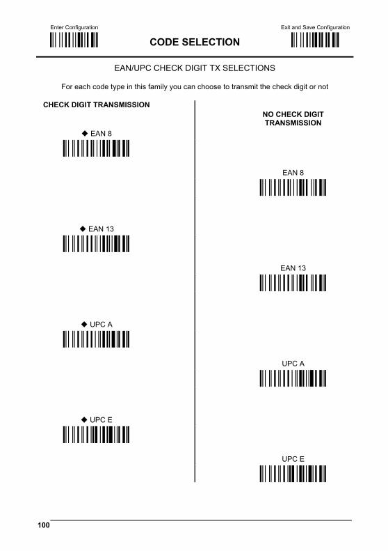
Enter Configuration Exit and Save Configuration
Ì$+;Î CODE SELECTION Ì$-?Î
100
EAN/UPC CHECK DIGIT TX SELECTIONS
For each code type in this family you can choose to transmit the check digit or not
CHECK DIGIT TRANSMISSION
EAN 8
NO CHECK DIGIT TRANSMISSION
ÌAAG1oÎ
EAN 8 ÌAAG0kÎ
EAN 13
ÌAAH1rÎ
EAN 13 ÌAAH0nÎ
UPC A
ÌAAI1uÎ
UPC A ÌAAI0qÎ
UPC E
ÌAAJ1xÎ
UPC E ÌAAJ0tÎ

Enter Configuration Exit and Save Configuration
Ì$+;Î CODE SELECTION Ì$-?Î
101
CONVERSION OPTIONS
UPC E to UPC A conversion
ÌAAAÄÎ
UPC E to EAN 13 conversion
UPC A to EAN 13 conversion
ÌAABÇÎ
ÌAACÊÎ
EAN 8 to EAN 13 conversion
Enable only ISBN conversion
ÌAAD"Î
ÌAP1nÎ
Enable only ISSN conversion
Enable both ISBN and ISSN conversion
ÌAP2qÎ
ÌAP3tÎ
Disable both ISBN and ISSN
conversion ÌAP0kÎ
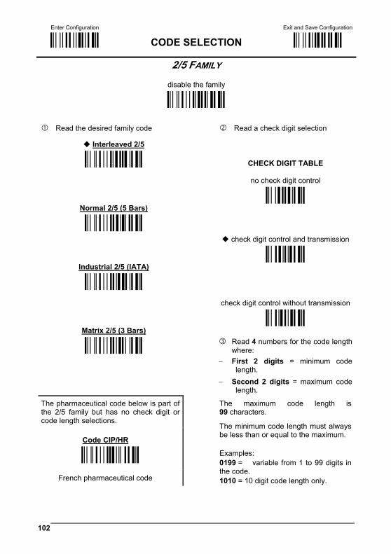
Enter Configuration Exit and Save Configuration
Ì$+;Î CODE SELECTION Ì$-?Î
102
2/5 FAMILY
disable the family
ÌAC0QÎ
Read the desired family code Read a check digit selection
Interleaved 2/5
ÌAC1TÎ
CHECK DIGIT TABLE
no check digit control
Normal 2/5 (5 Bars)
Ì12Î
ÌAC2WÎ
check digit control and transmission
Industrial 2/5 (IATA)
Ì23Î
ÌAC3ZÎ
check digit control without transmission
Matrix 2/5 (3 Bars)
Ì34Î
ÌAC4]Î Read 4 numbers for the code length
where: − First 2 digits = minimum code
length. − Second 2 digits = maximum code
length.
The pharmaceutical code below is part of the 2/5 family but has no check digit or code length selections.
Code CIP/HR
The maximum code length is 99 characters.
The minimum code length must always be less than or equal to the maximum.
ÌAC5`Î
French pharmaceutical code
Examples: 0199 = variable from 1 to 99 digits in the code. 1010 = 10 digit code length only.
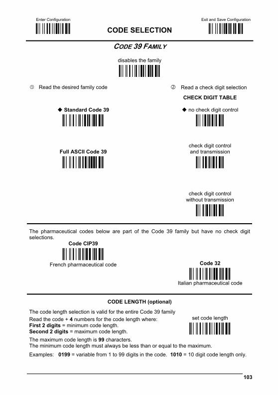
Enter Configuration Exit and Save Configuration
Ì$+;Î CODE SELECTION Ì$-?Î
103
CODE 39 FAMILY
disables the family
ÌAB0OÎ
Read the desired family code Read a check digit selection
Standard Code 39
CHECK DIGIT TABLE
no check digit control
ÌAB1RÎ Ì12Î
Full ASCII Code 39
check digit control and transmission
ÌAB2UÎ Ì23Î
check digit control without transmission
Ì34Î
The pharmaceutical codes below are part of the Code 39 family but have no check digit selections.
Code CIP39 ÌAB3XÎ
French pharmaceutical code
Code 32 ÌAB4[Î Italian pharmaceutical code
CODE LENGTH (optional)
The code length selection is valid for the entire Code 39 family Read the code + 4 numbers for the code length where: set code length First 2 digits = minimum code length. Second 2 digits = maximum code length. ÌAB*=Î
The maximum code length is 99 characters. The minimum code length must always be less than or equal to the maximum. Examples: 0199 = variable from 1 to 99 digits in the code. 1010 = 10 digit code length only.
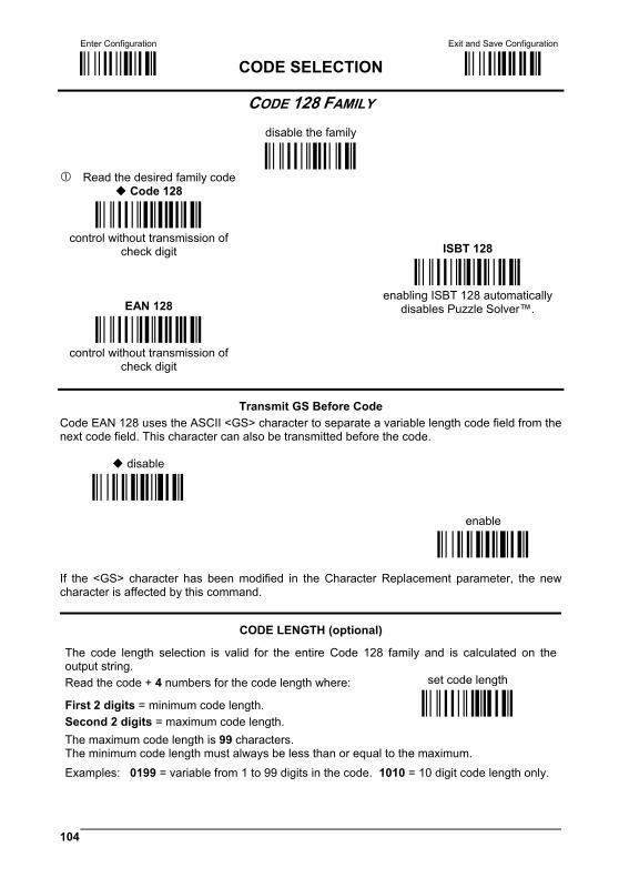
Enter Configuration Exit and Save Configuration
Ì$+;Î CODE SELECTION Ì$-?Î
104
CODE 128 FAMILY
disable the family
ÌAI0]Î Read the desired family code
Code 128
ÌAI11=Î control without transmission of
check digit
ISBT 128
EAN 128
ÌAI31CÎ enabling ISBT 128 automatically
disables Puzzle Solver™.
ÌAI21@Î control without transmission of
check digit
Transmit GS Before Code Code EAN 128 uses the ASCII <GS> character to separate a variable length code field from the next code field. This character can also be transmitted before the code.
disable
ÌEQ0qÎ
enable
ÌEQ1tÎ
If the <GS> character has been modified in the Character Replacement parameter, the new character is affected by this command.
CODE LENGTH (optional)
The code length selection is valid for the entire Code 128 family and is calculated on the output string. Read the code + 4 numbers for the code length where: set code length
First 2 digits = minimum code length. Second 2 digits = maximum code length.
ÌAILJÎ
The maximum code length is 99 characters. The minimum code length must always be less than or equal to the maximum. Examples: 0199 = variable from 1 to 99 digits in the code. 1010 = 10 digit code length only.
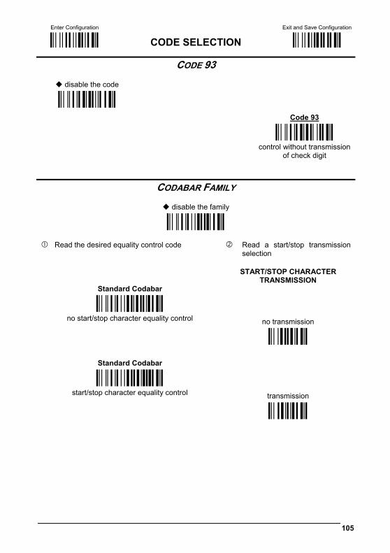
Enter Configuration Exit and Save Configuration
Ì$+;Î CODE SELECTION Ì$-?Î
105
CODE 93
disable the code
ÌAK0aÎ
Code 93
ÌAK1dÎ control without transmission
of check digit
CODABAR FAMILY
disable the family
ÌAD0SÎ
Read the desired equality control code Read a start/stop transmission selection
START/STOP CHARACTER
TRANSMISSION Standard Codabar
ÌAD113Î
no start/stop character equality control
no transmission
Ì12Î
Standard Codabar
ÌAD127Î
start/stop character equality control
transmission Ì23Î
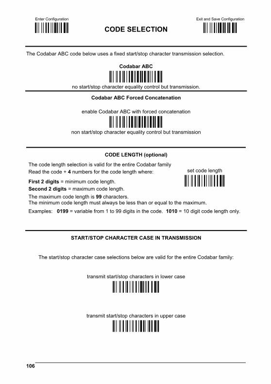
Enter Configuration Exit and Save Configuration
Ì$+;Î CODE SELECTION Ì$-?Î
106
The Codabar ABC code below uses a fixed start/stop character transmission selection.
Codabar ABC
ÌAD212)Î
no start/stop character equality control but transmission.
Codabar ABC Forced Concatenation
enable Codabar ABC with forced concatenation
ÌAD2321Î
non start/stop character equality control but transmission
CODE LENGTH (optional)
The code length selection is valid for the entire Codabar family Read the code + 4 numbers for the code length where: set code length
First 2 digits = minimum code length. Second 2 digits = maximum code length.
ÌAD*AÎ
The maximum code length is 99 characters. The minimum code length must always be less than or equal to the maximum. Examples: 0199 = variable from 1 to 99 digits in the code. 1010 = 10 digit code length only.
START/STOP CHARACTER CASE IN TRANSMISSION
The start/stop character case selections below are valid for the entire Codabar family:
transmit start/stop characters in lower case
ÌADA0_Î
transmit start/stop characters in upper case
ÌADA1cÎ
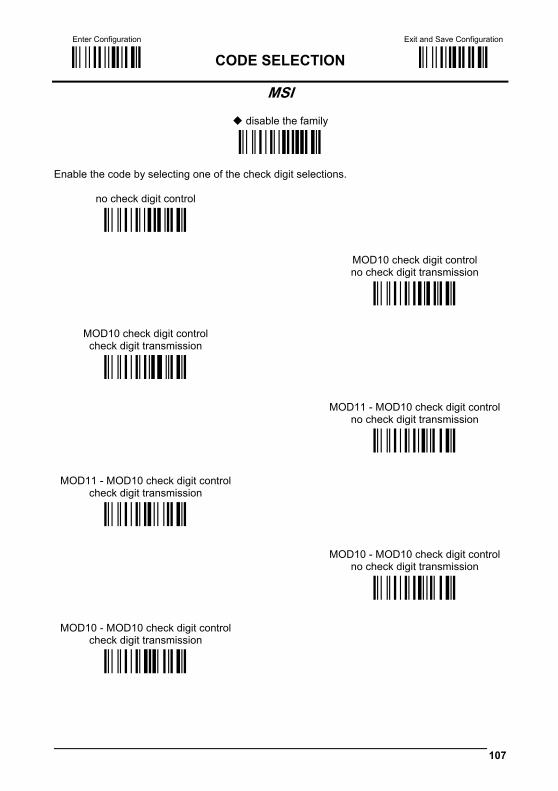
Enter Configuration Exit and Save Configuration
Ì$+;Î CODE SELECTION Ì$-?Î
107
MSI
disable the family
ÌAE0UÎ Enable the code by selecting one of the check digit selections.
no check digit control
ÌAE1XÎ
MOD10 check digit control no check digit transmission
ÌAE2[Î
MOD10 check digit control check digit transmission
ÌAE3^Î
MOD11 - MOD10 check digit control no check digit transmission
ÌAE4aÎ
MOD11 - MOD10 check digit control check digit transmission
ÌAE5dÎ
MOD10 - MOD10 check digit control no check digit transmission
ÌAE6gÎ
MOD10 - MOD10 check digit control check digit transmission
ÌAE7jÎ
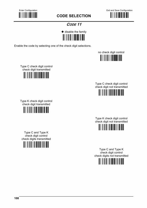
Enter Configuration Exit and Save Configuration
Ì$+;Î CODE SELECTION Ì$-?Î
108
CODE 11
disable the family
ÌAG0YÎ Enable the code by selecting one of the check digit selections. no check digit control ÌAG1\Î
Type C check digit control check digit transmitted
ÌAG21<Î
Type C check digit control check digit not transmitted
ÌAG22@Î
Type K check digit control check digit transmitted
ÌAG31?Î
Type K check digit control check digit not transmitted
ÌAG32CÎ Type C and Type K check digit control
check digits transmitted
ÌAG41BÎ
Type C and Type K check digit control
check digits not transmitted ÌAG42FÎ

Enter Configuration Exit and Save Configuration
Ì$+;Î CODE SELECTION Ì$-?Î
109
CODE 16K
disable the code
ÌAJ0_Î
Code 16K
ÌAJ1bÎ To read stacked codes, simply move the reader over the code so that each line of the code is scanned. During this process a series of brief “ticks” indicates that reading is proceeding correctly.
CODE 49
disable the code
ÌAM0eÎ
Code 49
ÌAM1hÎ To read stacked codes, simply move the reader over the code so that each line of the code is scanned. During this process a series of brief “ticks” indicates that reading is proceeding correctly.
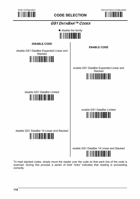
Enter Configuration Exit and Save Configuration
Ì$+;Î CODE SELECTION Ì$-?Î
110
GS1 DATABAR™ CODES
disable the family
ÌAQ0mÎ
DISABLE CODE
disable GS1 DataBar Expanded Linear and Stacked
ENABLE CODE
ÌAQ10IÎ
enable GS1 DataBar Expanded Linear and Stacked
disable GS1 DataBar Limited
ÌAQ11MÎ
ÌAQ20LÎ
enable GS1 DataBar Limited disable GS1 DataBar 14 Linear and Stacked
ÌAQ21PÎ
ÌAQ30OÎ enable GS1 DataBar 14 Linear and Stacked
ÌAQ31SÎ To read stacked codes, simply move the reader over the code so that each line of the code is scanned. During this process a series of brief “ticks” indicates that reading is proceeding correctly.

111
ADVANCED FORMATTING
NOT FOR PEN INTERFACES
CONCATENATION ADVANCED FORMATTING
NOTE
Please follow the setup procedure carefully for these parameters.
NOTE
The Advanced Formatting parameters may not be compatible with the IBM USB POS interface selection.
1. Read the Enter Configuration code ONCE, available at the top of page.
2. Read configuration codes precisely following the numbered procedure given.
= Read the code and follow the procedure given
= Default value
3. Read the Exit and Save Configuration code ONCE, available at the top of page.

Enter Configuration Exit and Save Configuration
Ì$+;Î ADVANCED FORMATTING Ì$-?Î
112
CONCATENATION
disable
ÌEI0aÎ
enable
ÌEI1dÎ Permits the concatenation of two codes defined by code type and length. It is possible to set a timeout for the second code reading and to define code transmission if the timeout expires. The order of transmission is CODE 1-CODE 2.
Define Concatenation
1 Code 1
code ID
ÌEK0eÎ
Read the code type from the Code Identifier Table beginning in Appendix B.
code length
ÌEL0gÎ
Read a number in the range 01-99 from the Hex/Numeric Table.
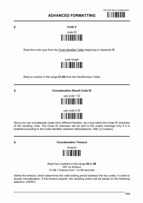
Exit and Save Configuration
ADVANCED FORMATTING Ì$-?Î
113
2 Code 2
code ID
ÌEK1hÎ
Read the code type from the Code Identifier Table beginning in Appendix B.
code length
ÌEL1jÎ
Read a number in the range 01-99 from the Hex/Numeric Table.
3 Concatenation Result Code ID
use code 1 ID
ÌEN0kÎ
use code 2 ID
ÌEN1nÎ
Since you can concatenate codes from different families, you must select the Code ID character of the resulting code. The Code ID character will be sent in the output message only if it is enabled according to the Code Identifier selection (Manufacturer, AIM, or Custom).
4 Concatenation Timeout
timeout
ÌEJ3Î
Read two numbers in the range 00 to 99 00= no timeout
01-99 = timeout from 1 to 99 seconds
Define the timeout, which determines the valid waiting period between the two codes, in order to accept concatenation. If the timeout expires, the resulting action will be based on the following selection. (HHDII)
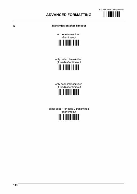
Exit and Save Configuration
ADVANCED FORMATTING Ì$-?Î
114
5 Transmission after Timeout
no code transmitted after timeout
ÌEM0iÎ
only code 1 transmitted (if read) after timeout
ÌEM1lÎ
only code 2 transmitted (if read) after timeout
ÌEM2oÎ
either code 1 or code 2 transmitted after timeout
ÌEM3rÎ
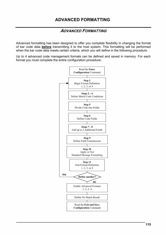
ADVANCED FORMATTING
115
ADVANCED FORMATTING Advanced formatting has been designed to offer you complete flexibility in changing the format of bar code data before transmitting it to the host system. This formatting will be performed when the bar code data meets certain criteria, which you will define in the following procedure.
Up to 4 advanced code management formats can be defined and saved in memory. For each format you must complete the entire configuration procedure:
Define another?
Enable Advanced Formats1, 2, 3, 4
Define No Match Result
Read the Exit and SaveConfiguration Command
Step 5Divide Code into Fields
Steps 7 - 8Add up to 2 Additional Fields
Step 1Begin Format Definition
1, 2, 3, or 4
Step 6Define Code Fields
Steps 2 - 4Define Match Code Conditions
Step 9Define Field Transmission
Step 10Apply or Not
Standard Message Formatting
Read the EnterConfiguration Command
Step 11End Format Definition
1, 2, 3, or 4
YES
NO
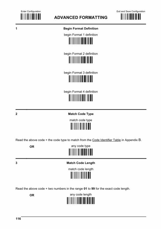
Enter Configuration Exit and Save Configuration
Ì$+;Î ADVANCED FORMATTING Ì$-?Î
116
1 Begin Format Definition
begin Format 1 definition
ÌHA0TÎ
begin Format 2 definition
ÌHA1WÎ
begin Format 3 definition
ÌHA2ZÎ
begin Format 4 definition
ÌHA3]Î
2 Match Code Type match code type
ÌHB&Î
Read the above code + the code type to match from the Code Identifier Table in Appendix B.
OR any code type ÌHB0VÎ
3 Match Code Length match code length
ÌHC(Î
Read the above code + two numbers in the range 01 to 99 for the exact code length.
OR any code length ÌHC001Î
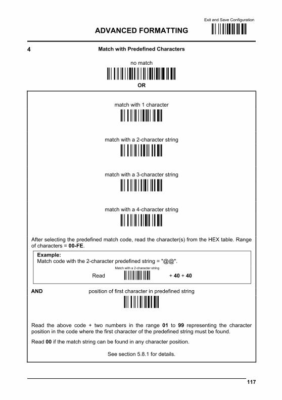
Exit and Save Configuration
ADVANCED FORMATTING Ì$-?Î
117
4 Match with Predefined Characters
no match ÌHD0HE00ÄÎ
OR
match with 1 character
ÌHD1]Î
match with a 2-character string
ÌHD2`Î
match with a 3-character string
ÌHD3cÎ
match with a 4-character string
ÌHD4fÎ
After selecting the predefined match code, read the character(s) from the HEX table. Range of characters = 00-FE.
Example: Match code with the 2-character predefined string = "@@".
Read
Match with a 2-character string
+ 40 + 40
AND position of first character in predefined string
ÌHE,Î
Read the above code + two numbers in the range 01 to 99 representing the character position in the code where the first character of the predefined string must be found.
Read 00 if the match string can be found in any character position.
See section 5.8.1 for details.
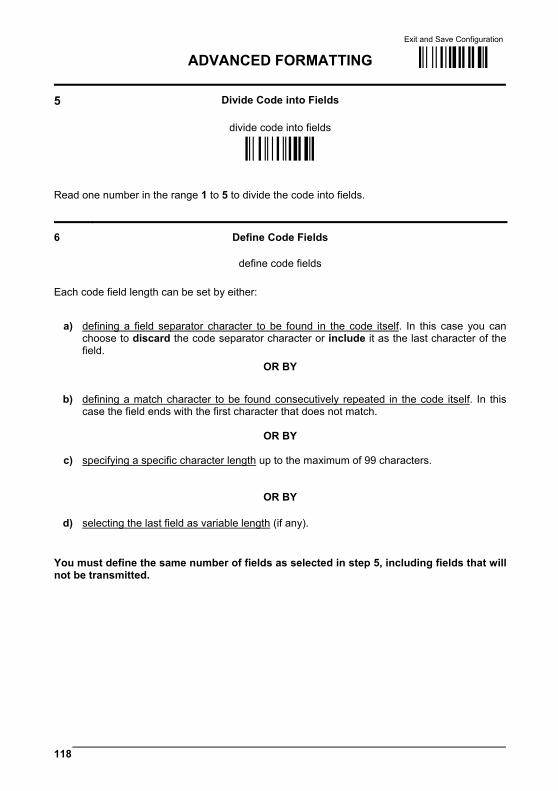
Exit and Save Configuration
ADVANCED FORMATTING Ì$-?Î
118
5 Divide Code into Fields
divide code into fields
ÌHF.Î
Read one number in the range 1 to 5 to divide the code into fields.
6 Define Code Fields
define code fields Each code field length can be set by either:
a) defining a field separator character to be found in the code itself. In this case you can choose to discard the code separator character or include it as the last character of the field.
OR BY
b) defining a match character to be found consecutively repeated in the code itself. In this case the field ends with the first character that does not match.
OR BY
c) specifying a specific character length up to the maximum of 99 characters.
OR BY
d) selecting the last field as variable length (if any). You must define the same number of fields as selected in step 5, including fields that will not be transmitted.

Exit and Save Configuration
ADVANCED FORMATTING Ì$-?Î
119
DEFINE FIELD 1 BY: EITHER
field separator
a) ÌHG0`Î
Read the field separator character from the HEX table. Range of characters = 00-FE. discard separator include separator
Ì01Î Ì12Î
OR
match character
b) ÌHG3iÎ
Read the match character from the HEX table. Range of characters = 00-FE.
OR
field length
c) ÌHG1cÎ
Read two numbers in the range 01 to 99 to define the field length.
OR
this is the last field (variable length)
d) ÌHG2fÎ
AND Field 1 Terminators
no field terminators ÌHH0bÎ
1 field terminator 2 field terminators
ÌHH1eÎ
ÌHH2hÎ
Read the field terminator character(s) from the HEX table. Valid range of characters for all readers = 00-FE. For Wedge and USB-KBD interface, it is also possible to read the Special Key(s) on page 75.

Exit and Save Configuration
ADVANCED FORMATTING Ì$-?Î
120
DEFINE FIELD 2 BY: EITHER
field separator
a) ÌHG0`Î
Read the field separator character from the HEX table. Range of characters = 00-FE. discard separator include separator
Ì01Î Ì12Î
OR
match character
b) ÌHG3iÎ
Read the match character from the HEX table. Range of characters = 00-FE.
OR
field length
c) ÌHG1cÎ
Read two numbers in the range 01 to 99 to define the field length.
OR
this is the last field (variable length)
d) ÌHG2fÎ
AND Field 2 Terminators
no field terminators ÌHH0bÎ
1 field terminator 2 field terminators
ÌHH1eÎ
ÌHH2hÎ
Read the field terminator character(s) from the HEX table. Valid range of characters for all readers = 00-FE. For Wedge and USB-KBD interface, it is also possible to read the Special Key(s) on page 75.
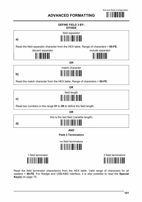
Exit and Save Configuration
ADVANCED FORMATTING Ì$-?Î
121
DEFINE FIELD 3 BY: EITHER
field separator
a) ÌHG0`Î
Read the field separator character from the HEX table. Range of characters = 00-FE. discard separator include separator
Ì01Î Ì12Î
OR
match character
b) ÌHG3iÎ
Read the match character from the HEX table. Range of characters = 00-FE.
OR
field length
c) ÌHG1cÎ
Read two numbers in the range 01 to 99 to define the field length.
OR
this is the last field (variable length)
d) ÌHG2fÎ
AND Field 3 Terminators
no field terminators ÌHH0bÎ
1 field terminator 2 field terminators
ÌHH1eÎ
ÌHH2hÎ
Read the field terminator character(s) from the HEX table. Valid range of characters for all readers = 00-FE. For Wedge and USB-KBD interface, it is also possible to read the Special Key(s) on page 75.
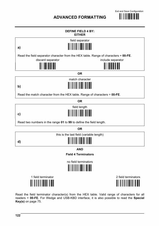
Exit and Save Configuration
ADVANCED FORMATTING Ì$-?Î
122
DEFINE FIELD 4 BY: EITHER
field separator
a) ÌHG0`Î
Read the field separator character from the HEX table. Range of characters = 00-FE. discard separator include separator
Ì01Î Ì12Î
OR
match character
b) ÌHG3iÎ
Read the match character from the HEX table. Range of characters = 00-FE.
OR
field length
c) ÌHG1cÎ
Read two numbers in the range 01 to 99 to define the field length.
OR
this is the last field (variable length)
d) ÌHG2fÎ
AND Field 4 Terminators
no field terminators ÌHH0bÎ
1 field terminator 2 field terminators
ÌHH1eÎ
ÌHH2hÎ
Read the field terminator character(s) from the HEX table. Valid range of characters for all readers = 00-FE. For Wedge and USB-KBD interface, it is also possible to read the Special Key(s) on page 75.
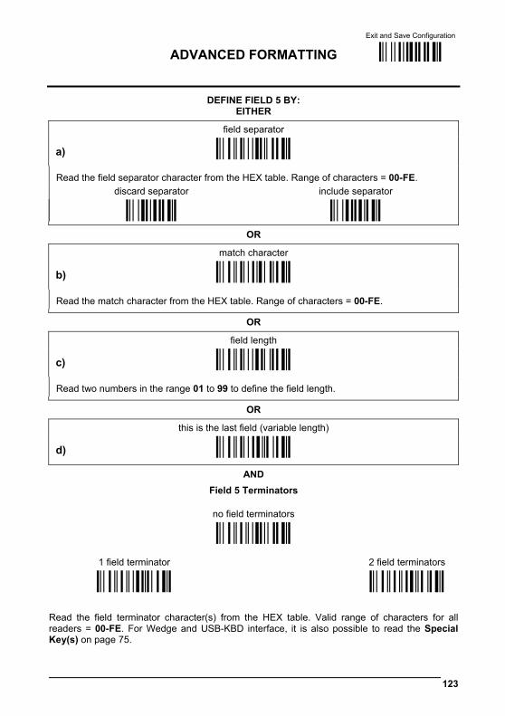
Exit and Save Configuration
ADVANCED FORMATTING Ì$-?Î
123
DEFINE FIELD 5 BY: EITHER
field separator
a) ÌHG0`Î
Read the field separator character from the HEX table. Range of characters = 00-FE. discard separator include separator
Ì01Î Ì12Î
OR
match character
b) ÌHG3iÎ
Read the match character from the HEX table. Range of characters = 00-FE.
OR
field length
c) ÌHG1cÎ
Read two numbers in the range 01 to 99 to define the field length.
OR
this is the last field (variable length)
d) ÌHG2fÎ
AND Field 5 Terminators
no field terminators ÌHH0bÎ
1 field terminator 2 field terminators
ÌHH1eÎ
ÌHH2hÎ
Read the field terminator character(s) from the HEX table. Valid range of characters for all readers = 00-FE. For Wedge and USB-KBD interface, it is also possible to read the Special Key(s) on page 75.
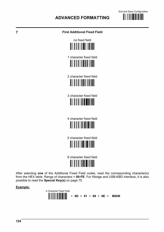
Exit and Save Configuration
ADVANCED FORMATTING Ì$-?Î
124
7 First Additional Fixed Field
no fixed field ÌHI0dÎ
1 character fixed field
ÌHI1gÎ
2 character fixed field
ÌHI2jÎ
3 character fixed field
ÌHI3mÎ
4 character fixed field
ÌHI4pÎ
5 character fixed field
ÌHI5sÎ
6 character fixed field
ÌHI6vÎ
After selecting one of the Additional Fixed Field codes, read the corresponding character(s) from the HEX table. Range of characters = 00-FE. For Wedge and USB-KBD interface, it is also possible to read the Special Key(s) on page 75. Example:
4 Character Fixed Field
+ 4D + 41 + 49 + 4E = MAIN
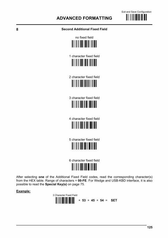
Exit and Save Configuration
ADVANCED FORMATTING Ì$-?Î
125
8 Second Additional Fixed Field
no fixed field ÌHJ0fÎ
1 character fixed field
ÌHJ1iÎ
2 character fixed field
ÌHJ2lÎ
3 character fixed field
ÌHJ3oÎ
4 character fixed field
ÌHJ4rÎ
5 character fixed field
ÌHJ5uÎ
6 character fixed field
ÌHJ6xÎ
After selecting one of the Additional Fixed Field codes, read the corresponding character(s) from the HEX table. Range of characters = 00-FE. For Wedge and USB-KBD interface, it is also possible to read the Special Key(s) on page 75. Example:
3 Character Fixed Field
+ 53 + 45 + 54 = SET

Exit and Save Configuration
ADVANCED FORMATTING Ì$-?Î
126
9 Field Transmission
number of fields to transmit
ÌHK8Î
Read one number in the range 1 to 7 for the number of fields to transmit. Include only fields to be transmitted.
Field Order Transmission Read the codes corresponding to the fields to transmit in the order in which they are to be transmitted. A field can be transmitted more than once. See example.
field 1
Ì12Î
field 2
field 3
Ì23Î
Ì34Î
field 4
field 5
Ì45Î
Ì56Î
additional field 1
additional field 2
Ì67Î
Ì78Î
Example: The bar code is divided into 3 defined fields plus 1 additional fixed field. Transmit in the order: Field 2, Additional Field 1, Field 1, Field 2.
Number of Fieldsto Transmit
+ 4 + Field 2
+ Additional Field 1
+ Field 1
+ Field 2
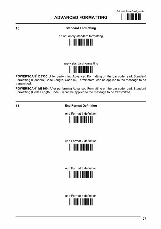
Exit and Save Configuration
ADVANCED FORMATTING Ì$-?Î
127
10 Standard Formatting
do not apply standard formatting ÌHL0jÎ
apply standard formatting ÌHL1mÎ
POWERSCAN® D8330: After performing Advanced Formatting on the bar code read, Standard Formatting (Headers, Code Length, Code ID, Terminators) can be applied to the message to be transmitted. POWERSCAN® M8300: After performing Advanced Formatting on the bar code read, Standard Formatting (Code Length, Code ID) can be applied to the message to be transmitted.
11 End Format Definition
end Format 1 definition ÌHM0lÎ
end Format 2 definition ÌHM1oÎ
end Format 3 definition ÌHM2rÎ
end Format 4 definition ÌHM3uÎ

Enter Configuration Exit and Save Configuration
Ì$+;Î ADVANCED FORMATTING Ì$-?Î
128
Enable Advanced Format no Advanced Formats enabled ÌHN0nÎ
Advanced Format 1 enable
ÌHN11NÎ
disable ÌHN10JÎ
Advanced Format 2 enable
ÌHN21QÎ
disable ÌHN20MÎ
Advanced Format 3 enable
ÌHN31TÎ
disable ÌHN30PÎ
Advanced Format 4 enable
ÌHN41WÎ
disable ÌHN40SÎ
Enter Configuration Exit and Save Configuration
Ì$+;Î ADVANCED FORMATTING Ì$-?Î
129
No Match Result
clear data - no transmission
ÌHO0pÎ transmit data using standard
format ÌHO1sÎ
This selection determines the action to be taken when codes read do not conform to the advanced format requisites (no match). • Codes not matching can be ignored, cleared from memory and not transmitted. • Codes not matching can be transmitted using the Standard formatting (Headers, Code
Length, Code ID, Terminators).
130
RADIO PARAMETERS
PowerScan® M8300 Series readers only
RADIO PROTOCOL TIMEOUT RADIO RX TIMEOUT POWER-OFF TIMEOUT TRANSMISSION MODE
BEEPER CONTROL FOR RADIO RESPONSE
SINGLE STORE BATCH MODE FIND ME
1. Read the Enter Configuration code ONCE, available at the top of each page.
2. Read configuration codes from the desired groups.
= Read the code and follow the procedure given
3. Read the Exit and Save Configuration code ONCE, available at the top of each page.
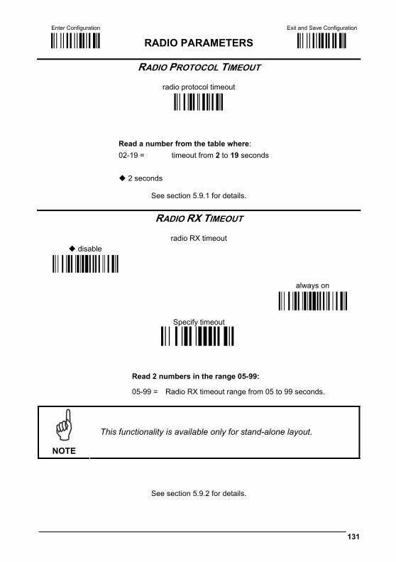
Enter Configuration Exit and Save Configuration
Ì$+;Î RADIO PARAMETERS Ì$-?Î
131
RADIO PROTOCOL TIMEOUT
radio protocol timeout
ÌRH<Î
Read a number from the table where: 02-19 = timeout from 2 to 19 seconds
2 seconds
See section 5.9.1 for details.
RADIO RX TIMEOUT
radio RX timeout disable
always on
Specify timeout
Read 2 numbers in the range 05-99:
05-99 = Radio RX timeout range from 05 to 99 seconds.
NOTE
This functionality is available only for stand-alone layout.
See section 5.9.2 for details.

Enter Configuration Exit and Save Configuration
Ì$+;Î RADIO PARAMETERS Ì$-?Î
132
POWER-OFF TIMEOUT
power-off timeout
ÌRPLÎ
Read 2 numbers in the range 00-99: 00 = Power-off disabled; reader always ready 01-99 = corresponds to a max. 99 hour delay before power-off.
power-off after 4 hours.
See par 5.9.3 for details.
TRANSMISSION MODE
One Way
ÌRI0nÎ
Two-ways
ÌRI1qÎ
See section 5.9.4 for details.
Enter Configuration Exit and Save Configuration
Ì$+;Î RADIO PARAMETERS Ì$-?Î
133
BEEPER CONTROL FOR RADIO RESPONSE
normal
ÌBF0XÎ
only good decode
only good reception
ÌBF1[Î
ÌBF2^Î
off ÌBF3aÎ
See section 5.9.5 for details.
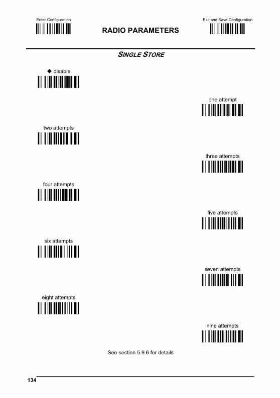
Enter Configuration Exit and Save Configuration
Ì$+;Î RADIO PARAMETERS Ì$-?Î
134
SINGLE STORE
disable
ÌRO0zÎ
one attempt
two attempts
ÌRO1}Î
ÌRO2ÄÎ
three attempts
four attempts
ÌRO3ÇÎ
ÌRO4ÊÎ
five attempts
six attempts
ÌRO5"Î
ÌRO6%Î
seven attempts
eight attempts
ÌRO7(Î
ÌRO8+Î
nine attempts
ÌRO9.Î
See section 5.9.6 for details
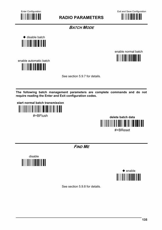
Enter Configuration Exit and Save Configuration
Ì$+;Î RADIO PARAMETERS Ì$-?Î
135
BATCH MODE
disable batch
enable normal batch
ÌBZ0ÄÎ enable automatic batch
ÌBZ1ÇÎ
ÌBZ2ÊÎ
See section 5.9.7 for details.
The following batch management parameters are complete commands and do notrequire reading the Enter and Exit configuration codes.
start normal batch transmission
Ì#+BFlush]Î #+BFlush delete batch data
Ì#+BReset\Î #+BReset
FIND ME
disable
enable
ÌBk0;Î
ÌBk1>Î
See section 5.9.8 for details.
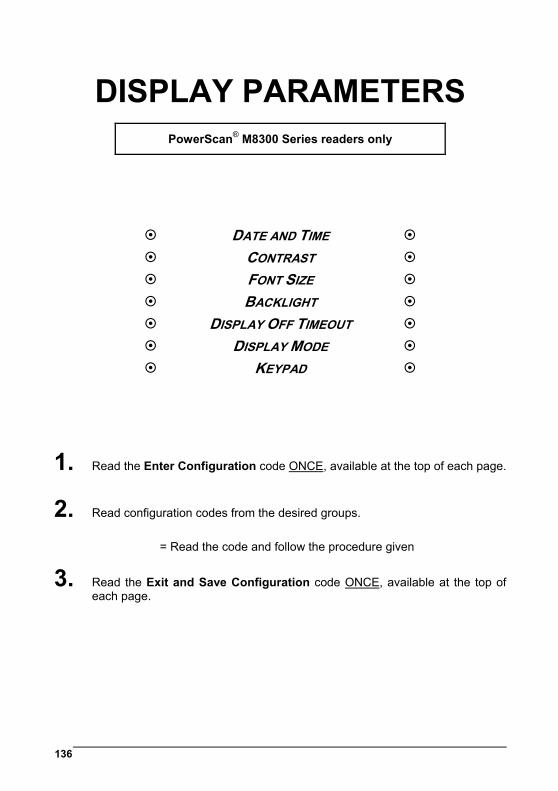
136
DISPLAY PARAMETERS
PowerScan® M8300 Series readers only
DATE AND TIME CONTRAST FONT SIZE BACKLIGHT DISPLAY OFF TIMEOUT DISPLAY MODE KEYPAD
1. Read the Enter Configuration code ONCE, available at the top of each page.
2. Read configuration codes from the desired groups.
= Read the code and follow the procedure given
3. Read the Exit and Save Configuration code ONCE, available at the top of each page.
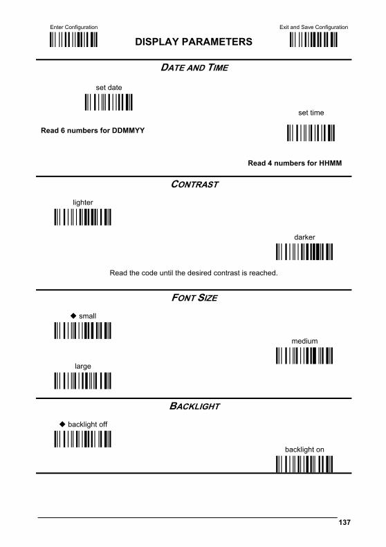
Enter Configuration Exit and Save Configuration
Ì$+;Î DISPLAY PARAMETERS Ì$-?Î
137
DATE AND TIME
set date
ÌIA%Î
set time
Read 6 numbers for DDMMYY
ÌIB'Î
Read 4 numbers for HHMM
CONTRAST
lighter
ÌIC0YÎ
darker ÌIC1\Î
Read the code until the desired contrast is reached.
FONT SIZE
small
ÌID0[Î
medium
large ÌID1^Î
ÌID2aÎ
BACKLIGHT
backlight off
ÌIE0]Î
backlight on
ÌIE1`Î
Enter Configuration Exit and Save Configuration
Ì$+;Î DISPLAY PARAMETERS Ì$-?Î
138
DISPLAY-OFF TIMEOUT
timeout
ÌIF/Î
Read 2 numbers in the range 00-99: 00 = disables display timeout (always on) 01 to 99 = timeout from 1 to 99 seconds.
display-off after 8 seconds.
delay disabled
DISPLAY MODE
normal
ÌIG0aÎ
local echo
clear display after decode
ÌIG1dÎ
ÌIG2gÎ
See section 5.10.1 for details.
Enter Configuration Exit and Save Configuration
Ì$+;Î DISPLAY PARAMETERS Ì$-?Î
139
KEYPAD
disable reader keypad
ÌIK0iÎ
enable reader keypad and select characters
ÌIK1lÎ
Read 3 HEX characters in the range 00-FE, corresponding to the left, center and right keys respectively. FF = KeyID disabled
left = '<' center = '=' right = '>'
See section 6.2 for details.
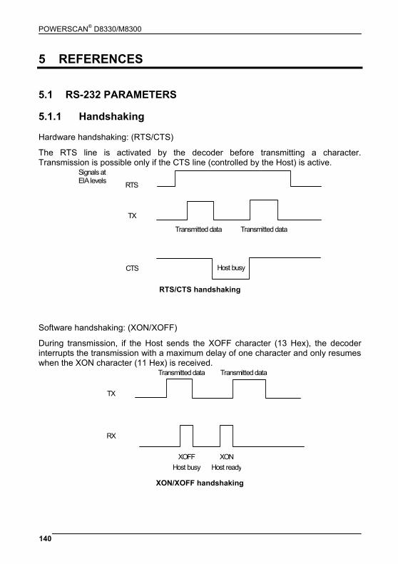
POWERSCAN® D8330/M8300
140
5 REFERENCES 5.1 RS-232 PARAMETERS 5.1.1 Handshaking Hardware handshaking: (RTS/CTS)
The RTS line is activated by the decoder before transmitting a character. Transmission is possible only if the CTS line (controlled by the Host) is active.
RTS
Transmitted data Transmitted data
TX
CTS Host busy
Signals at EIA levels
RTS/CTS handshaking
Software handshaking: (XON/XOFF)
During transmission, if the Host sends the XOFF character (13 Hex), the decoder interrupts the transmission with a maximum delay of one character and only resumes when the XON character (11 Hex) is received.
Host readyHost busyXON XOFF
RX
Transmitted dataTransmitted data
TX
XON/XOFF handshaking
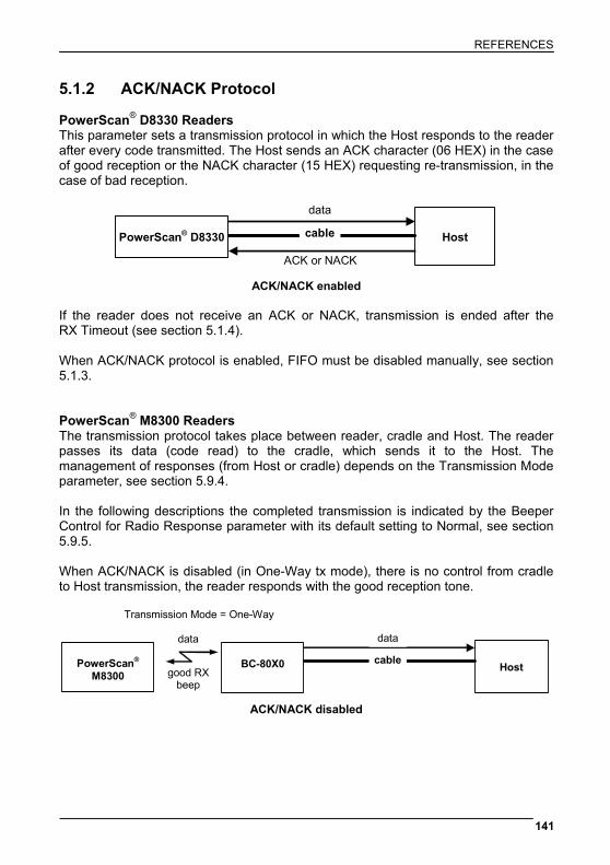
REFERENCES
141
5.1.2 ACK/NACK Protocol PowerScan® D8330 Readers This parameter sets a transmission protocol in which the Host responds to the reader after every code transmitted. The Host sends an ACK character (06 HEX) in the case of good reception or the NACK character (15 HEX) requesting re-transmission, in the case of bad reception.
PowerScan® D8330 Host
ACK or NACK
data
cable
ACK/NACK enabled
If the reader does not receive an ACK or NACK, transmission is ended after the RX Timeout (see section 5.1.4). When ACK/NACK protocol is enabled, FIFO must be disabled manually, see section 5.1.3. PowerScan® M8300 Readers The transmission protocol takes place between reader, cradle and Host. The reader passes its data (code read) to the cradle, which sends it to the Host. The management of responses (from Host or cradle) depends on the Transmission Mode parameter, see section 5.9.4. In the following descriptions the completed transmission is indicated by the Beeper Control for Radio Response parameter with its default setting to Normal, see section 5.9.5. When ACK/NACK is disabled (in One-Way tx mode), there is no control from cradle to Host transmission, the reader responds with the good reception tone.
BC-80X0 Host
data
cable
PowerScan® M8300
data
Transmission Mode = One-Way
good RX beep
ACK/NACK disabled
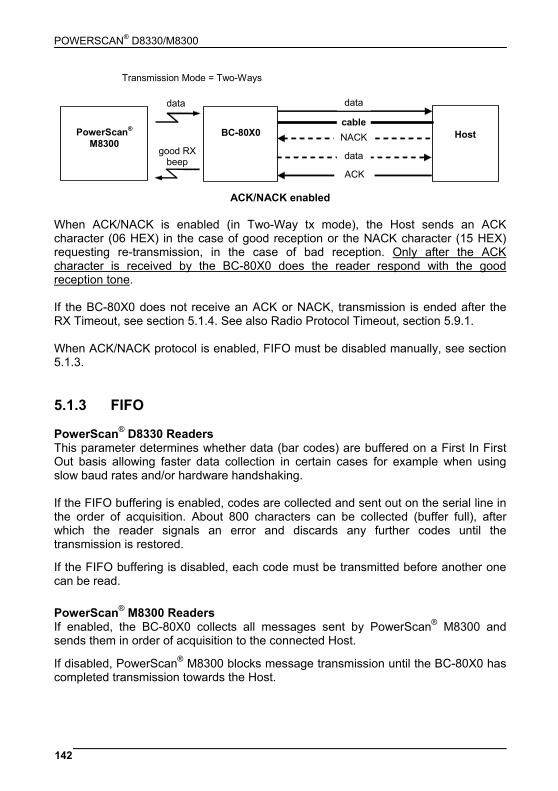
POWERSCAN® D8330/M8300
142
BC-80X0
Host
data
cable
PowerScan® M8300
data
NACK
ACK
good RX beep
Transmission Mode = Two-Ways
data
ACK/NACK enabled
When ACK/NACK is enabled (in Two-Way tx mode), the Host sends an ACK character (06 HEX) in the case of good reception or the NACK character (15 HEX) requesting re-transmission, in the case of bad reception. Only after the ACK character is received by the BC-80X0 does the reader respond with the good reception tone. If the BC-80X0 does not receive an ACK or NACK, transmission is ended after the RX Timeout, see section 5.1.4. See also Radio Protocol Timeout, section 5.9.1. When ACK/NACK protocol is enabled, FIFO must be disabled manually, see section 5.1.3. 5.1.3 FIFO PowerScan® D8330 Readers This parameter determines whether data (bar codes) are buffered on a First In First Out basis allowing faster data collection in certain cases for example when using slow baud rates and/or hardware handshaking. If the FIFO buffering is enabled, codes are collected and sent out on the serial line in the order of acquisition. About 800 characters can be collected (buffer full), after which the reader signals an error and discards any further codes until the transmission is restored. If the FIFO buffering is disabled, each code must be transmitted before another one can be read. PowerScan® M8300 Readers If enabled, the BC-80X0 collects all messages sent by PowerScan® M8300 and sends them in order of acquisition to the connected Host. If disabled, PowerScan® M8300 blocks message transmission until the BC-80X0 has completed transmission towards the Host.
REFERENCES
143
5.1.4 RX Timeout When the RS-232 interface is selected, the Host can be used to configure the device by sending it command strings (see Appendix A). This parameter can be used to automatically end data reception from the Host after the specified period of time. If no character is received from the Host, after the timeout expires, any incomplete string (any string not terminated by <CR>) is flushed from the device buffer. 5.2 PEN PARAMETERS 5.2.1 Minimum Output Pulse This parameter sets the duration of the output pulse corresponding to the narrowest element in the bar code. In this way the code resolution is controlled by the signal sent to the decoder, independently of the physical resolution of the code read. The shortest pulse (200 μs) corresponds to a high-resolution code emulation and therefore a shorter transfer speed to the decoder (for decoders able to work on high resolution codes). Likewise, longer pulses correspond to low-resolution code emulation and therefore a longer transfer time to the decoder. 5.2.2 Conversion to Code 39 and Code 128 PowerScan® D8330 Series Readers When using these readers it is possible to convert all codes to Code 39. By disabling this option the decoded codes will be transmitted in their original format, except for the following codes, which are ALWAYS converted into Code 39 format: MSI, Code 11, Code 16K, Code 49, GS1 DataBar™. PowerScan® M8300 Series Readers When using these readers it is possible to choose between converting the decoded codes into either Code 39 format or Code 128 format. It is not possible to disable conversion.

POWERSCAN® D8330/M8300
144
5.2.3 Overflow This parameter generates a white space before the first bar and after the last bar of the code. The selections are as follows: narrow = space 10 times the minimum output pulse. medium = space 20 times the minimum output pulse. wide = space 30 times the minimum output pulse. 5.2.4 Output and Idle Levels The following state diagrams describe the different output and idle level combinations for Pen emulation:
bar
spacewhite
black
barcode output
idle
OUTPUT: Normal
IDLE: Normal
bar
spacewhite
black
barcode output
idle
OUTPUT: Normal
IDLE: Inverted
bar
spacewhite
black barcode output
idle IDLE: Normal
OUTPUT: Inverted
bar space
white
black barcode output
idle
IDLE: Inverted
OUTPUT: Inverted
Output and Idle Levels
REFERENCES
145
5.2.5 Inter-Block Delay For the PEN Emulation interface, data are sent to the Host in fixed size blocks of 20 characters each. The inter-block delay parameter allows setting a delay between each block sent to the Host. 5.3 NETWORK PARAMETERS 5.3.1 Slave Address Range First/Last These parameters define the valid addresses for the Slave cradles on the network. Valid values are in the range 0 to 1999. However, the maximum number of cradles in a single network is 16, (including the Master if present). All cradles in the system must have different addresses. To reduce system boot time, it is recommended to number the Slaves consecutively, while it is not necessary that the Master cradle address is contained in the range. The network addresses correspond to the radio addresses, see section 4.7. At system power-up, the Master searches for and initializes all the Slaves found in the valid address range. During this phase the yellow LED on the Master cradle blinks. The time to complete the start up procedure varies depending on the complexity of the network but is typically between a few seconds to a few minutes. Start up cannot be interrupted. At the end of this procedure the system will be operative and can collect data from all devices.
CAUTION
All Slaves must be powered up either before or together with the Master. Slaves successively powered will not be recognized by the system even if their address is in the specified range.
5.3.2 Network Warning Message The Master cradle can transmit warning messages to the Host regarding some network errors.
/*Slave xxxx not responding*/: when the Master can no longer communicate with the specified Slave previously identified at start up.
/*Frame out of sequence for terminal xxxx*/: if a reader is sending data packets out of sequence. This can happen if there are transmission problems on the network (either connection or communication), or if the reader has correctly transmitted data to a device not on the network (reader configuration error).
POWERSCAN® D8330/M8300
146
The message is sent in the following format:
"Message" CR LF 5.3.3 Reception Warning Message The Master cradle can transmit warning messages to the Host regarding wrong reception of data. Example:
/*Two-Ways Out of Sequence!(.....)*/
This message is transmitted to the Host by the Master cradle when the Master cradle receives a closing string from the Host for a Two-way tx communication, but this was either not open or already closed, therefore the data will be lost. See section 5.9.4. 5.3.4 Master Header/Terminator Selection In addition to the standard header/terminator selection, the Master cradle can add its own header/terminator to the entire message sent to the Host. In the STAR-System™ network headers and terminators for all RF Devices are disabled by default. The Master header and terminator default values are as follows depending on the interface selection towards the Host:
RS-232: no header, terminator CR-LF WEDGE: no header, terminator ENTER
See sections 5.4.1 and 5.4.2. 5.4 DATA FORMAT For an overview of Message Formatting see Chapter 6. 5.4.1 Header/Terminator Selection The header/terminator selection is not effected by the reading of the restore default code. In fact, header and terminator default values depend on the interface selection:
RS-232: no header, terminator CR-LF WEDGE: no header, terminator ENTER
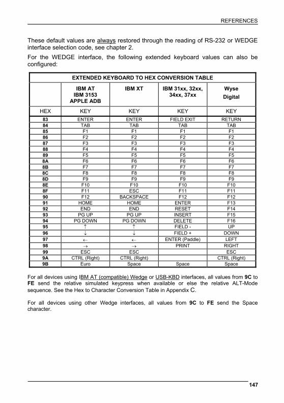
REFERENCES
147
These default values are always restored through the reading of RS-232 or WEDGE interface selection code, see chapter 2. For the WEDGE interface, the following extended keyboard values can also be configured:
EXTENDED KEYBOARD TO HEX CONVERSION TABLE
IBM AT IBM 3153
APPLE ADB
IBM XT IBM 31xx, 32xx, 34xx, 37xx
Wyse Digital
HEX KEY KEY KEY KEY 83 ENTER ENTER FIELD EXIT RETURN 84 TAB TAB TAB TAB 85 F1 F1 F1 F1 86 F2 F2 F2 F2 87 F3 F3 F3 F3 88 F4 F4 F4 F4 89 F5 F5 F5 F5 8A F6 F6 F6 F6 8B F7 F7 F7 F7 8C F8 F8 F8 F8 8D F9 F9 F9 F9 8E F10 F10 F10 F10 8F F11 ESC F11 F11 90 F12 BACKSPACE F12 F12 91 HOME HOME ENTER F13 92 END END RESET F14 93 PG UP PG UP INSERT F15 94 PG DOWN PG DOWN DELETE F16 95 ↑ ↑ FIELD - UP 96 ↓ ↓ FIELD + DOWN 97 ← ← ENTER (Paddle) LEFT 98 → → PRINT RIGHT 99 ESC ESC ESC 9A CTRL (Right) CTRL (Right) CTRL (Right) 9B Euro Space Space Space
For all devices using IBM AT (compatible) Wedge or USB-KBD interfaces, all values from 9C to FE send the relative simulated keypress when available or else the relative ALT-Mode sequence. See the Hex to Character Conversion Table in Appendix C. For all devices using other Wedge interfaces, all values from 9C to FE send the Space character.

Enter Configuration Exit and Save Configuration
Ì$+;Î Ì$-?Î
148
5.4.2 Define Special Key Sequence The Special Key(s) for Wedge IBM AT-PS/2 and USB-KBD interface users can be associated with a sequence of keyboard keys that otherwise could not be selected, i.e. ALT + F6, SHIFT + F1. These Special Keys can be used for: - Headers/Terminators - Character Replacement - Field Adjustment - Custom Code ID - Advanced Formatting – Define Field - Advanced Formatting – Additional Fixed Field
Follow the procedure to define the desired Special Key sequence:
1. Read the Enter Configuration code above and select the Special Key to define (one at a time):
Define Special Key 1 ÌFQ9C2>Î
Define Special Key 2 ÌFQ9D2BÎ
Define Special Key 3 ÌFQ9E2FÎ
Define Special Key 4 ÌFQ9F2JÎ
Define Special Key 5 ÌFQA02qÎ
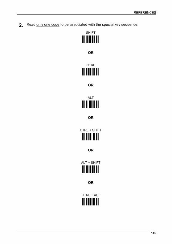
REFERENCES
149
2. Read only one code to be associated with the special key sequence:
SHIFT Ì12Î
OR
CTRL Ì23Î
OR
ALT Ì45Î
OR
CTRL + SHIFT Ì34Î
OR
ALT + SHIFT Ì56Î
OR
CTRL + ALT Ì67Î
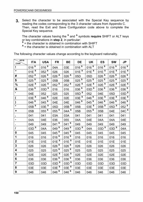
POWERSCAN® D8330/M8300
150
3. Select the character to be associated with the Special Key sequence by reading the codes corresponding to the 3 character values from Appendix C. Then, read the Exit and Save Configuration code above to complete the Special Key sequence.
The character values having the S and A symbols require SHIFT or ALT keys or key combinations in step 2, in particular: S = the character is obtained in combination with SHIFT A = the character is obtained in combination with ALT
The following character values change according to the keyboard nationality.
ITA USA FR BE DE UK ES SW JP ! 016 S 016 S 04A 03E 016 S 016 S 016 S 016 S 016 S " 01E S 052 S 026 026 01E S 01E S 01E S 01E S 01E S # 052 A 026 S 026 A 026 A 05D 05D 026 A 026 S 026 S $ 025 S 025 S 05B 05B 025 S 025 S 025 S 025 A 025 S % 02E S 02E S 052 S 052 S 02E S 02E S 02E S 02E S 02E S & 036 S 03D S 016 016 036 S 03D S 036 S 036 S 036 S ' 04E 052 025 025 05D S 052 04E 05D 03D S ( 03E S 046 S 02E 02E 03E S 046 S 03E S 03E S 03E S ) 046 S 045 S 04E 04E 046 S 045 S 046 S 046 S 046 S * 05B S 03E S 05D 05B S 05B 03E S 05B S 05D S 052 S + 05B 055 S 055 S 04A S 05B 055 S 05B 04E 04C S , 041 041 03A 03A 041 041 041 041 041 - 04A 04E 036 055 04A 04E 04A 04A 04E . 049 049 041 S 041 S 049 049 049 049 049 / 03D S 04A 049 S 049 S 03D S 04A 03D S 03D S 04A 0 045 045 045 S 045 S 045 045 045 045 045 1 016 016 016 S 016 S 016 016 016 016 016 2 01E 01E 01E S 01E S 01E 01E 01E 01E 01E 3 026 026 026 S 026 S 026 026 026 026 026 4 025 025 025 S 025 S 025 025 025 025 025 5 02E 02E 02E S 02E S 02E 02E 02E 02E 02E 6 036 036 036 S 036 S 036 036 036 036 036 7 03D 03D 03D S 03D S 03D 03D 03D 03D 03D 8 03E 03E 03E S 03E S 03E 03E 03E 03E 03E 9 046 046 046 S 046 S 046 046 046 046 046
CHAR
KEYB

REFERENCES
151
ITA USA FR BE DE UK ES SW JP : 049 S 04C S 049 049 049 S 04C S 049 S 049 S 052 ; 041 S 04C 041 041 041 S 04C 041 S 041 S 04C < 061 041 S 061 061 061 041 S 061 061 041 S = 045 S 055 055 04A 045 S 055 045 S 045 S 04E S > 061 S 049 S 061 S 061 S 061 S 049 S 061 S 061 S 049 S ? 04E 04A S 03A S 03A S 04E S 04A S 04E S 04E S 04A S @ 04C A 01E S 045 A 01E A 015 A 052 S 01E A 01E A 054 [ 054 A 054 02E A 054 A 052 S 054 054 A 03E A 05B \ 00E 05D 03E A 061 A 04C S 061 00E A 04E A 051 ] 05B A 05B 04E A 05B A 054 S 05B 05B A 046 A 05D ^ 055 S 036 S 046 A 054 00E 036 S 054 S 05B S 055 _ 04A S 04E S 03E 055 04A S 04E S 04A S 04A S 051 S ’ (accent) - 00E 03D A 05D A 055 S 00E 054 055 S 054 S a 01C 01C 015 015 01C 01C 01C 01C 01C b 032 032 032 032 032 032 032 032 032 c 021 021 021 021 021 021 021 021 021 d 023 023 023 023 023 023 023 023 023 e 024 024 024 024 024 024 024 024 024 f 02B 02B 02B 02B 02B 02B 02B 02B 02B g 034 034 034 034 034 034 034 034 034 h 033 033 033 033 033 033 033 033 033 i 043 043 043 043 043 043 043 043 043 j 03B 03B 03B 03B 03B 03B 03B 03B 03B k 042 042 042 042 042 042 042 042 042 l 04B 04B 04B 04B 04B 04B 04B 04B 04B m 03A 03A 04C 04C 03A 03A 03A 03A 03A n 031 031 031 031 031 031 031 031 031 o 044 044 044 044 044 044 044 044 044 p 04D 04D 04D 04D 04D 04D 04D 04D 04D q 015 015 01C 01C 015 015 015 015 015 r 02D 02D 02D 02D 02D 02D 02D 02D 02D s 01B 01B 01B 01B 01B 01B 01B 01B 01B t 02C 02C 02C 02C 02C 02C 02C 02C 02C u 03C 03C 03C 03C 03C 03C 03C 03C 03C v 02A 02A 02A 02A 02A 02A 02A 02A 02A
CHAR
KEYB
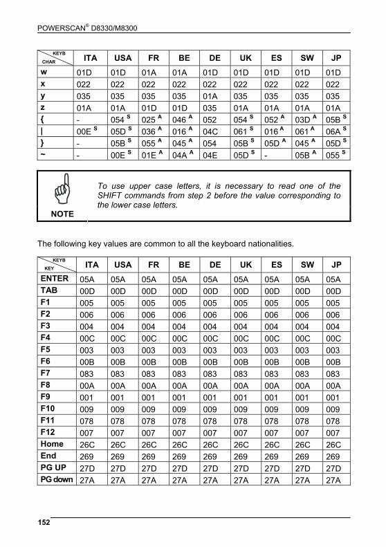
POWERSCAN® D8330/M8300
152
ITA USA FR BE DE UK ES SW JP w 01D 01D 01A 01A 01D 01D 01D 01D 01D x 022 022 022 022 022 022 022 022 022 y 035 035 035 035 01A 035 035 035 035 z 01A 01A 01D 01D 035 01A 01A 01A 01A { - 054 S 025 A 046 A 052 054 S 052 A 03D A 05B S | 00E S 05D S 036 A 016 A 04C 061 S 016 A 061 A 06A S } - 05B S 055 A 045 A 054 05B S 05D A 045 A 05D S ~ - 00E S 01E A 04A A 04E 05D S - 05B A 055 S
NOTE
To use upper case letters, it is necessary to read one of the SHIFT commands from step 2 before the value corresponding to the lower case letters.
The following key values are common to all the keyboard nationalities.
ITA USA FR BE DE UK ES SW JP ENTER 05A 05A 05A 05A 05A 05A 05A 05A 05A TAB 00D 00D 00D 00D 00D 00D 00D 00D 00D F1 005 005 005 005 005 005 005 005 005 F2 006 006 006 006 006 006 006 006 006 F3 004 004 004 004 004 004 004 004 004 F4 00C 00C 00C 00C 00C 00C 00C 00C 00C F5 003 003 003 003 003 003 003 003 003 F6 00B 00B 00B 00B 00B 00B 00B 00B 00B F7 083 083 083 083 083 083 083 083 083 F8 00A 00A 00A 00A 00A 00A 00A 00A 00A F9 001 001 001 001 001 001 001 001 001 F10 009 009 009 009 009 009 009 009 009 F11 078 078 078 078 078 078 078 078 078 F12 007 007 007 007 007 007 007 007 007 Home 26C 26C 26C 26C 26C 26C 26C 26C 26C End 269 269 269 269 269 269 269 269 269 PG UP 27D 27D 27D 27D 27D 27D 27D 27D 27D PG down 27A 27A 27A 27A 27A 27A 27A 27A 27A
CHAR
KEYB
KEY
KEYB
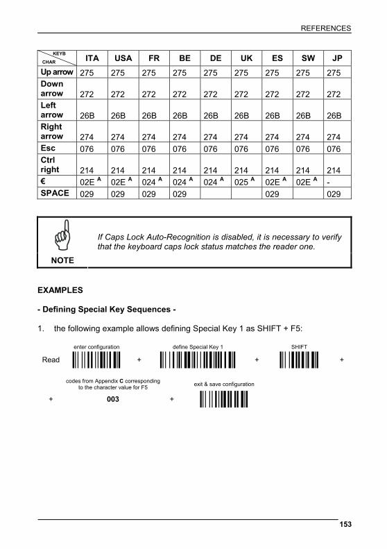
REFERENCES
153
ITA USA FR BE DE UK ES SW JP Up arrow 275 275 275 275 275 275 275 275 275 Down arrow 272 272 272 272 272 272 272 272 272 Left arrow 26B 26B 26B 26B 26B 26B 26B 26B 26B Right arrow 274 274 274 274 274 274 274 274 274 Esc 076 076 076 076 076 076 076 076 076 Ctrl right 214 214 214 214 214 214 214 214 214 € 02E A 02E A 024 A 024 A 024 A 025 A 02E A 02E A - SPACE 029 029 029 029 029 029
NOTE
If Caps Lock Auto-Recognition is disabled, it is necessary to verify that the keyboard caps lock status matches the reader one.
EXAMPLES - Defining Special Key Sequences - 1. the following example allows defining Special Key 1 as SHIFT + F5:
enter configuration define Special Key 1 SHIFT
Read Ì$+;Î + ÌFQ9C2>Î + Ì12Î +
codes from Appendix C corresponding
to the character value for F5 exit & save configuration
+ 003 + Ì$-?Î
CHAR
KEYB
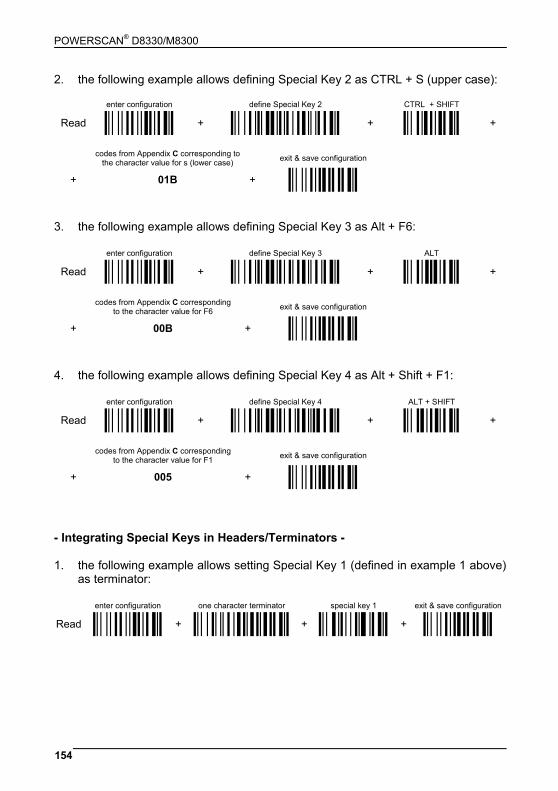
POWERSCAN® D8330/M8300
154
2. the following example allows defining Special Key 2 as CTRL + S (upper case):
enter configuration define Special Key 2 CTRL + SHIFT
Read Ì$+;Î + ÌFQ9D2BÎ + Ì34Î +
codes from Appendix C corresponding to
the character value for s (lower case) exit & save configuration
+ 01B + Ì$-?Î 3. the following example allows defining Special Key 3 as Alt + F6:
enter configuration define Special Key 3 ALT
Read Ì$+;Î + ÌFQ9E2FÎ + Ì45Î +
codes from Appendix C corresponding
to the character value for F6 exit & save configuration
+ 00B + Ì$-?Î 4. the following example allows defining Special Key 4 as Alt + Shift + F1:
enter configuration define Special Key 4 ALT + SHIFT
Read Ì$+;Î + ÌFQ9F2JÎ + Ì56Î +
codes from Appendix C corresponding
to the character value for F1 exit & save configuration
+ 005 + Ì$-?Î - Integrating Special Keys in Headers/Terminators - 1. the following example allows setting Special Key 1 (defined in example 1 above)
as terminator:
enter configuration one character terminator special key 1 exit & save configuration
Read Ì$+;Î + ÌEA111Î + Ì9CÄÎ + Ì$-?Î
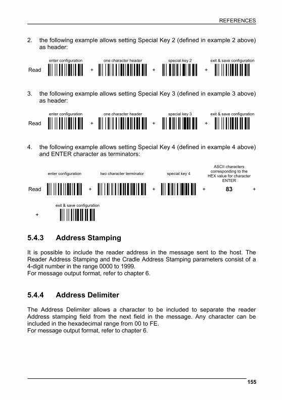
REFERENCES
155
2. the following example allows setting Special Key 2 (defined in example 2 above) as header:
enter configuration one character header special key 2 exit & save configuration
Read Ì$+;Î + ÌEA01.Î + Ì9DÆÎ + Ì$-?Î 3. the following example allows setting Special Key 3 (defined in example 3 above)
as header:
enter configuration one character header special key 3 exit & save configuration
Read Ì$+;Î + ÌEA01.Î + Ì9EÈÎ + Ì$-?Î 4. the following example allows setting Special Key 4 (defined in example 4 above)
and ENTER character as terminators:
enter configuration two character terminator special key 4
ASCII characters corresponding to the
HEX value for character ENTER
Read Ì$+;Î + ÌEA125Î + Ì9FÊÎ + 83 +
exit & save configuration
+ Ì$-?Î 5.4.3 Address Stamping It is possible to include the reader address in the message sent to the host. The Reader Address Stamping and the Cradle Address Stamping parameters consist of a 4-digit number in the range 0000 to 1999. For message output format, refer to chapter 6. 5.4.4 Address Delimiter The Address Delimiter allows a character to be included to separate the reader Address stamping field from the next field in the message. Any character can be included in the hexadecimal range from 00 to FE. For message output format, refer to chapter 6.
POWERSCAN® D8330/M8300
156
5.4.5 Time Stamping Format The Time Stamping parameter sets the format for hour and date information. It consists of 1 or 2 groups of numbers, each one made up of 6 decimal digits. For example, setting the Hour/Minutes/Seconds/Month/Day/Year format, the information 17:03:16 on June 12, 2002 will be formatted as 170316061202. 5.4.6 Time Stamping Delimiter The Time Stamping Delimiter allows a character to be included to separate the Time Stamping field from the next field in the message. Any character can be included in the hexadecimal range from 00 to FE. 5.5 POWER SAVE 5.5.1 Sleep State When using interfaces other than USB, this mode allows the μP in the reader to enter a “Sleep” state for minimum power consumption. For D-series readers, this command is only valid when hardware trigger type is selected.
Before entering Sleep mode, the following are verified: • no commands coming from Host • no data being transmitted to Host • Enter Sleep Timeout ended (see section 5.5.2)
To exit Sleep mode press the trigger. For M8300 series readers, sleep state is entered immediately after reading a code and is not configurable. To exit Sleep mode press the trigger. When using the USB interface, this mode allows the device to manage Selective Suspend conditions generated by the Host Operating System in which optimizing low power consumption (ex. Windows Stand-by). It is possible to exit the Suspend mode either from the Host (ex. moving the mouse during Stand-by) or through the bar code reader. The latter, called Remote Wakeup, makes the device wake up the Host restoring the communication. Remote Wakeup is possible by pressing the trigger.
REFERENCES
157
5.5.2 Enter Sleep Timeout For readers that have the Sleep state enabled, this timeout determines when the reader will enter this state. 5.6 READING PARAMETERS 5.6.1 Trigger Signal This mode determines how the reading phase is controlled when the hardware trigger operating mode is selected:
• trigger active level: the reader goes ON when the trigger is pressed and goes OFF when it is released
• trigger active pulse: the reader goes ON at the first trigger press and goes OFF only at a second press
5.6.2 Trigger Click When enabled, it activates a "click" sound upon each trigger pressure. 5.6.3 Trigger-Off Timeout When this timeout is selected, the reader turns OFF automatically after the desired period of time. 5.6.4 Reads per Cycle In general, a reading cycle corresponds to the ON + OFF times of a device. The resulting effects of this parameter on code reading depend on other related configuration conditions. Here are the definitions of ON and OFF times.
• For readers using the software trigger parameter (FLASH MODE), a reading cycle corresponds to the flash on + flash off times. Code reading takes place during the flash on time.
• For readers using the hardware trigger parameter, a reading cycle corresponds to a trigger press (ON) + one of the following OFF events:
trigger release (for trigger active level) a second trigger press (for trigger active pulse) trigger-off timeout (see section 5.6.3).
POWERSCAN® D8330/M8300
158
When one read per cycle is selected, the device decodes only one code during the ON period and immediately turns the reader OFF. It is only possible to read another code when the next ON time occurs.
In multiple reads per cycle, the ON period is extended so that the device can continue decoding codes until an OFF event occurs. For software trigger mode, the flash on period is immediately reset after each read and therefore extended. If another code is decoded before the reset flash on period expires, it is again reset and the effect is that the device remains ON, decoding codes until the flash on or timeout period expires. The Safety Time parameter should be used in this case to avoid unwanted multiple reading of the same code, see section 5.6.5. 5.6.5 Safety Time Safety time prevents the device from immediately decoding the same code more than once. Same code consecutive reading can be disabled requiring the reader to be removed from the code (no decoding) for at least 400 ms, or a timeout can be set up to 9.9 seconds before the decoder will accept the same code. Reading is immediate if the code changes. The safety time parameter is not applicable when reading stacked codes or when setting one read per cycle in hardware trigger operating mode, since these settings require voluntary action by the user. 5.7 DECODING PARAMETERS
CAUTION
These parameters are intended to enhance the decoding capability of the reader for particular applications. Used incorrectly, they can degrade the reading performance or increase the possibility of a decoding error.
5.7.1 Ink-Spread The ink-spread parameter allows the decoding of codes, which are not perfectly printed because the page texture tends to absorb the ink. 5.7.2 Overflow Control The overflow control parameter can be disabled when decoding codes printed on small surfaces, which do not allow the use of an overflow space. This command does not affect code families 2/5, Code 128 and Code 93.
REFERENCES
159
5.7.3 Interdigit Control The interdigit control parameter verifies the interdigit spacing for code families Code 39 and Codabar. 5.8 ADVANCED FORMATTING 5.8.1 Match Conditions Selecting an Advanced Formatting and specifying a Match restriction (Code Type, Code Length, Predefined Characters) the code will be transmitted according to the order of the defined formats. For example, defining 2 formats where: • Format 1: Match Code type = Code128 • Format 2: Match Code length = 15 and Match with Predefined Characters
“DATA”
a Code128 “DATA:12345ABCDE” with code length 15 will be formatted following the Format 1. To send the same code with the Format 2 it is necessary to invert the format order as follows: • Format 1: Match Code length = 15 and Match with Predefined Characters
“DATA” • Format 2: Match Code type = Code128 5.9 RADIO PARAMETERS (M8300 SERIES ONLY) 5.9.1 Radio Protocol Timeout This parameter sets the valid time to wait before transmission between the M8300 series reader and BC-80X0 cradle is considered failed. This parameter should be set taking into consideration the radio traffic (number of readers in the same area). If the RS-232 interface is used with ACK/NACK enabled, this parameter should be at least equal to the RX Timeout parameter for low traffic environments. It should be increased if there are many readers in the same area. It can be set between 2 and 19 seconds.
POWERSCAN® D8330/M8300
160
5.9.2 Radio RX Timeout When the scanner is used in a standalone layout (point-to-point or with multiple readers) it can be configured to receive “asynchronous” messages from the host at any time. There are two modes which can enable the scanner to receive messages from the host:
1) Enable “2 way” Communication Protocol – After the transmission of each bar code, the scanner waits for an acknowledgement from the host1. A message can be sent by the host accompanying this acknowledgement, or in place of it, to display something on the screen or execute a command (such as sound a beep sequence, turn an LED on or off, etc.). If no acknowledgement or message is received from the host within a programmable timeout duration, the radio will be switched off and an “error transmission” beep will be sounded.
2) Independent of the Selected Protocol – The scanner can be configured to keep the radio receiver “awake” for a defined period of time following each transmission. Any message coming from the host1 before expiration of the timeout is accepted. The parameter “Radio RX Timeout” is used for specifying how long the scanner have to wait for a message after receiving each code transmission. In this mode, the radio can also be “awakened” by pressing the trigger. The scanner can receive a message only if it is linked to the Base (i.e. the scanner has been joined to the Base and has had at last one “valid” transmission after the last power-on). Setting the “Radio RX timeout” value to “00” specifies that the radio never goes into sleep mode (always awake
the scanner can receive a message at any time). Choosing this setting will, of course, consume battery life more quickly.
1See Section 6.1 for Host to Scanner message formatting. 5.9.3 Power-Off Timeout If this command is enabled, after the desired timeout in hours, the PowerScan® batteries are disconnected and all power consumption ceases. To restore power, press the trigger once. The reader will now be ready to read codes. Power-off does not affect configuration parameters.
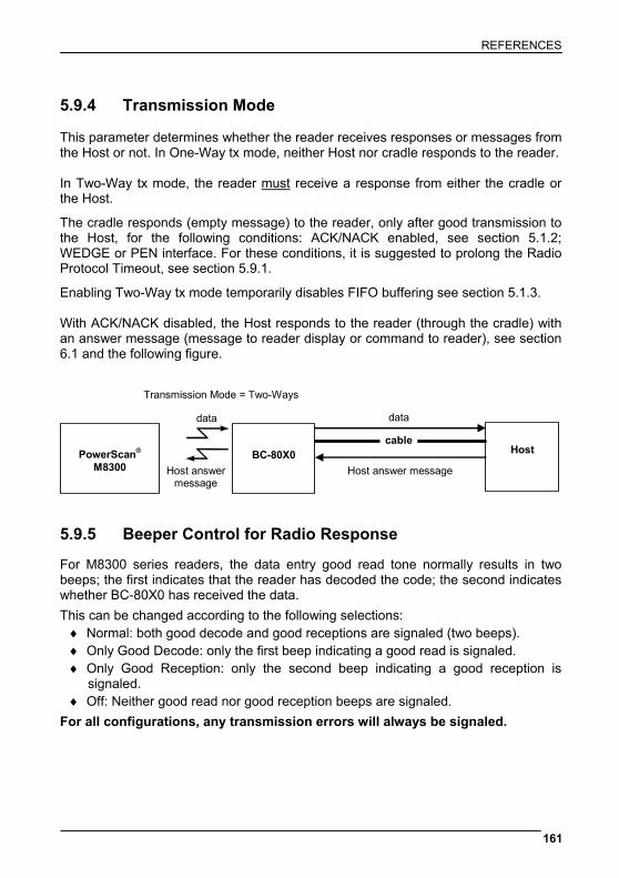
REFERENCES
161
5.9.4 Transmission Mode This parameter determines whether the reader receives responses or messages from the Host or not. In One-Way tx mode, neither Host nor cradle responds to the reader. In Two-Way tx mode, the reader must receive a response from either the cradle or the Host.
The cradle responds (empty message) to the reader, only after good transmission to the Host, for the following conditions: ACK/NACK enabled, see section 5.1.2; WEDGE or PEN interface. For these conditions, it is suggested to prolong the Radio Protocol Timeout, see section 5.9.1.
Enabling Two-Way tx mode temporarily disables FIFO buffering see section 5.1.3. With ACK/NACK disabled, the Host responds to the reader (through the cradle) with an answer message (message to reader display or command to reader), see section 6.1 and the following figure.
BC-80X0 Host
data
cable
PowerScan® M8300
data
Transmission Mode = Two-Ways
Host answer message Host answer message
5.9.5 Beeper Control for Radio Response For M8300 series readers, the data entry good read tone normally results in two beeps; the first indicates that the reader has decoded the code; the second indicates whether BC-80X0 has received the data.
This can be changed according to the following selections: ♦ Normal: both good decode and good receptions are signaled (two beeps). ♦ Only Good Decode: only the first beep indicating a good read is signaled. ♦ Only Good Reception: only the second beep indicating a good reception is
signaled. ♦ Off: Neither good read nor good reception beeps are signaled.
For all configurations, any transmission errors will always be signaled.
POWERSCAN® D8330/M8300
162
5.9.6 Single Store When single store mode is enabled, if the PowerScan® M8300 fails to transmit a code to the cradle, it enters a special operating mode that prevents the user from reading bar codes. When such operating mode is entered, the trigger no longer enables bar code reading but is used to retry transmission itself for the number of attempts selected in configuration. Once the transmission is successful the reader returns to the standard mode. If transmission is not successful after the number of configured attempts, the code is discarded. Single store may be useful if you often read codes at the limit of the coverage area and there is a chance that code transmission can fail. In such case single store allows you to move to a more favorable position or location (i.e. closer to the cradle) and retry transmission without the necessity of re-reading the code since it is already stored in the reader.
Conversely, if single store is disabled, and the user wants to retry transmission, the code must be read again, and therefore the attempt must be made from basically the same location. If the user gives up, he does not know if the transaction was successful. (Actually the transmission could have been successful but the cradle may have been unable to acknowledge the message). There are applications in which there is no risk of transmission failure. In such cases it may be better to disable single store so that the user perceives a more consistent behavior of the trigger in that it always corresponds to code reading. 5.9.7 Batch Mode This Operating Mode allows storing read codes in the internal reader RAM memory. The stored codes are transmitted to the base station at a later time according to the type of batch mode selected. Batch mode can be enabled either manually (normal batch mode) or automatically. Normal batch mode temporarily suspends radio communication between reader and base station allowing codes to be stored in the reader on a FIFO basis. This can be useful for example, if codes must be read from a location where there is no radio network. Upon returning to the system working area, this mode requires reading the Start Normal Batch Transmission bar code to successively transmit the list of stored codes to the base station. The FIFO management assures that the first code read will be the first code to be transmitted to the base station. The Delete Batch Data bar code allows canceling all bar code data stored in the reader. Automatic batch mode allows codes to be stored in the reader on a FIFO basis whenever the reader is out of radio range. In this case radio communication is not suspended and transmission is attempted after each code read. If transmission
REFERENCES
163
cannot be successfully completed, then the code is added to the list. When the reader returns in range, transmission of the codes to the base station resumes automatically, according to the selected communication protocol, upon simply pressing and releasing the trigger or by successfully reading a new code. Each code is listed on the reader display together with its identifying position number and its total number of characters. The three keys under the display have the following function in batch mode:
Key Function
▲ (left) Key Scroll up in list
ENTER (center) Key Delete highlighted code
▼ (right) Key Scroll down in list In batch mode, the selected Transmission Mode determines the behavior of the reader at the time the list of codes is transmitted. If One-way mode is enabled, the codes are transmitted one after the other without interruption. In Two-way mode, after transmitting each code, the reader waits for the Host answer message to be shown on the display. Therefore, in Two-way transmission mode and normal batch mode, the Start Normal Batch Transmission bar code must be read after each code to continue, whereas with automatic batch mode just pull and release the trigger after each code. The code, which has a transmission pending, is shown on the display in reverse video indicating that it cannot be deleted. 5.9.8 Find Me (PowerScan® M8300 only) If enabled, after a timeout of a few minutes in which PowerScan® M8300 is not used, it enters stand-by mode and its green LED starts blinking in order to signal its location.
POWERSCAN® D8330/M8300
164
5.10 DISPLAY PARAMETERS (SOME M8300 MODELS ONLY) 5.10.1 Display Mode The user can control the reader display behavior according to the following selections:
Normal mode: When a bar code is read with the reader: • The code is sent to the Host. • The reader display is not cleared. Therefore if any previous data was displayed
on the reader screen it remains. • There is no Local Echo to the reader display.
Clear Display After Decode mode: When a bar code is read with the reader: • The code is sent to the Host. • The reader display is cleared. Therefore if any previous data was displayed on
the reader screen it is cancelled and the screen remains blank. • There is no Local Echo of the code to the reader display.
Local Echo mode: When a bar code is read with the reader: • The code is sent to the Host. • The reader display is cleared. • The code is also sent to the reader display (Local Echo). • The cursor is positioned after the last printed character on the reader display. Host messages sent to the reader are always written to the reader display.

REFERENCES
165
5.11 CONFIGURATION EDITING COMMANDS The following commands carry out their specific function and then exit the configuration environment.
Command Description
Ì$+$*oÎ
Restore PowerScan® reader default configuration (see the relative Quick Reference Guide for default settings)
Ì$+$!KÎ
Transmit the PowerScan® D8330 or PowerScan® M8300 software release
Ì$+$&_Î
Transmit PowerScan® reader configuration in ASCII format. This command is not effective with Pen emulation interface.
Ì$+RX0$-qÎ
Restore BC-80X0 default configuration (see the relative Quick Reference Guide for default settings)
Ì$+RX1$-vÎ
Transmit the BC-80X0 Software release.
Ì$+RX2$-{Î
Transmit BC-80X0 configuration in ASCII format. This command is not effective with Pen emulation interface.
POWERSCAN® D8330/M8300
166
5.12 CUSTOM DEFAULT CONFIGURATION Read the following code to set the reader user-defined configuration as custom default configuration:
Save User-defined Configuration as Custom Default
Ì$+$0ÂÎ Read the following code whenever you need to restore the custom default configuration:
Restore Custom Default Configuration
Ì$+$1$Î 5.13 CODE TYPE RECOGNITION This procedure allows the reader to enter a particular state during which it reads and transmits to the Host information about the family type of codes unknown to the user (with the exception of MSI, Code 49 and Code 16k code types). It is also possible to read and transmit configuration strings without interpreting them. All codes are read ignoring the check digit. Follow the given procedure:
Read the following code to enter the code type recognition mode:
code type recognition
Ì#+CODEÂÎ
Read existing codes whose family type you need to check.
Read the following code to return to the reader's normal functioning:
exit code type recognition mode
Ì$-?Î
REFERENCES
167
5.14 CONFIGURATION COPYING COMMANDS 5.14.1 Copy PowerScan® D8330 Series Procedure:
Connect the master (correctly configured reader) and the slave (reader to be configured) together through two RS-232 serial interface cables and external power supply. Accessory cables and power supply are available from your Psion Teklogix distributor to provide this connection.
RS-232 Cables: CAB471 & CAB472
Power Supply: PG5
Using the slave reader, read the Restore Default bar code and then the RS-232 interface bar code from chapter 4 of this manual or from the Quick Reference Guide.
With the master reader, read the Configuration Copy bar code below.
Copy Configuration
Ì$+ZZ0$-*Î
The configuration will be copied from the master to the slave reader. The slave reader signals the end of the procedure with a series of beeps. Note: The master reader can be configured for any interface.
POWERSCAN® D8330/M8300
168
5.14.2 Copy PowerScan® M8300 Series Procedure:
Using the slave reader and its BC-80X0 cradle, follow the initialization procedure in chapter 4 of this manual or from the Quick Reference Guide.
With the master PowerScan® M8300 (correctly configured reader), read the
Copy Configuration bar code below. Then place it onto an BC-80X0 cradle within 10 seconds. The reader will beep indicating the configuration has been copied.
The configuration will be simultaneously sent over the RS-232 interface of the
BC-80X0. If this causes undesired effects disconnect the RS-232 cable between the PC and BC-80X0 during this process.
Copy Configuration
Ì$+ZZ0$-*Î
With the slave PowerScan® M8300, read the Get Configuration bar code below.
Then place it onto the same BC-80X0 cradle used in the step above. The slave reader's address will not be changed.
Get Configuration
Ì$+ZZ2$-4Î
The configuration will be copied from the master to the slave PowerScan® M8300. The slave PowerScan® M8300 signals the end of the procedure with a series of beeps. It is now ready to be used with its own BC-80X0 cradle.
Repeat the procedure above to configure other slave readers. The BC-80X0 can continue to configure slave readers until it receives another command or data.
REFERENCES
169
5.14.3 Copy BC-80X0 Procedure:
Using the slave reader and its BC-80X0 cradle, read the Restore Default bar code, set the radio address, and then read the RS-232 interface bar code from chapter 4 of this manual or from the Quick Reference Guide.
Connect the master BC-80X0 and the slave BC-80X0 (cradle to be configured)
together through two RS-232 serial interface cables and external power supply. Accessory cables and power supply are available from your Psion Teklogix distributor to provide this connection.
RS-232 Cables: CAB471 & CAB472
Power Supply: PG12
Read the Configuration Copy bar code below with a reader. Then place it onto the master BC-80X0 cradle.
Copy Configuration
Ì$+ZZ3$-9Î
The configuration will be copied from the master BC-80X0 to the slave BC-80X0. The reader signals the end of the procedure with a series of beeps.
Repeat the procedure above to configure other slave cradles.
Note: The master BC-80X0 can be configured for any interface.
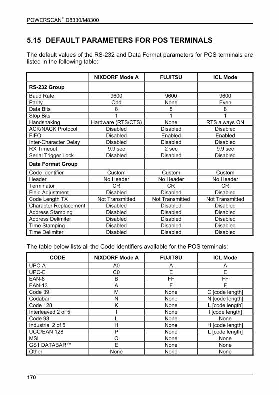
POWERSCAN® D8330/M8300
170
5.15 DEFAULT PARAMETERS FOR POS TERMINALS The default values of the RS-232 and Data Format parameters for POS terminals are listed in the following table:
NIXDORF Mode A FUJITSU ICL Mode
RS-232 Group Baud Rate 9600 9600 9600 Parity Odd None Even Data Bits 8 8 8 Stop Bits 1 1 1 Handshaking Hardware (RTS/CTS) None RTS always ON ACK/NACK Protocol Disabled Disabled Disabled FIFO Disabled Enabled Enabled Inter-Character Delay Disabled Disabled Disabled RX Timeout 9.9 sec 2 sec 9.9 sec Serial Trigger Lock Disabled Disabled Disabled Data Format Group
Code Identifier Custom Custom Custom Header No Header No Header No Header Terminator CR CR CR Field Adjustment Disabled Disabled Disabled Code Length TX Not Transmitted Not Transmitted Not Transmitted Character Replacement Disabled Disabled Disabled Address Stamping Disabled Disabled Disabled Address Delimiter Disabled Disabled Disabled Time Stamping Disabled Disabled Disabled Time Delimiter Disabled Disabled Disabled
The table below lists all the Code Identifiers available for the POS terminals:
CODE NIXDORF Mode A FUJITSU ICL Mode UPC-A A0 A A UPC-E C0 E E EAN-8 B FF FF EAN-13 A F F Code 39 M None C [code length] Codabar N None N [code length] Code 128 K None L [code length] Interleaved 2 of 5 I None I [code length] Code 93 L None None Industrial 2 of 5 H None H [code length] UCC/EAN 128 P None L [code length] MSI O None None GS1 DATABAR™ E None None Other None None None
REFERENCES
171
5.16 FIRMWARE UPGRADE Device firmware upgrades can be performed using the Downloader utility tool (downloadable from the original manufacturer’s web site: http://www.scanning.datalogic.com) from your PC through the USB communication. Procedure:
Launch the Downloader tool on your PC.
Connect the device to the PC via USB interface.
Read the code given below and position the reader onto the cradle:
prepare device for firmware upgrade
Ì$+RN2$-SÎ OR
Press the cradle button if present (to only update the cradle). The device will automatically be reset.
Proceed with the firmware upgrade (see the Downloader utility help on-line for
details).
CAUTION
Do not interrupt firmware upgrade downloading for any reason.
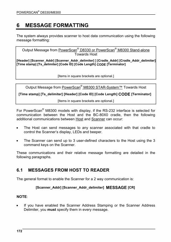
POWERSCAN® D8330/M8300
172
6 MESSAGE FORMATTING The system always provides scanner to host data communication using the following message formatting:
Output Message from PowerScan® D8330 or PowerScan® M8300 Stand-alone Towards Host
[Header] [Scanner_Addr] [Scanner_Addr_delimiter] ] [Cradle_Addr] [Cradle_Addr_delimiter] [Time stamp] [Ts_delimiter] [Code ID] [Code Length] CODE [Terminator]
[Items in square brackets are optional.]
Output Message from PowerScan® M8300 STAR-System™ Towards Host
[Time stamp] [Ts_delimiter] [Header] [Code ID] [Code Length] CODE [Terminator] [Items in square brackets are optional.]
For PowerScan® M8300 models with display, if the RS-232 interface is selected for communication between the Host and the BC-80X0 cradle, then the following additional communications between Host and Scanner can occur: • The Host can send messages to any scanner associated with that cradle to
control the Scanner’s display, LEDs and beeper. • The Scanner can send up to 3 user-defined characters to the Host using the 3
command keys on the Scanner. These communications and their relative message formatting are detailed in the following paragraphs. 6.1 MESSAGES FROM HOST TO READER The general format to enable the Scanner for a 2 way communication is:
[Scanner_Addr] [Scanner_Addr_delimiter] MESSAGE [CR] NOTE: • If you have enabled the Scanner Address Stamping or the Scanner Address
Delimiter, you must specify them in every message.
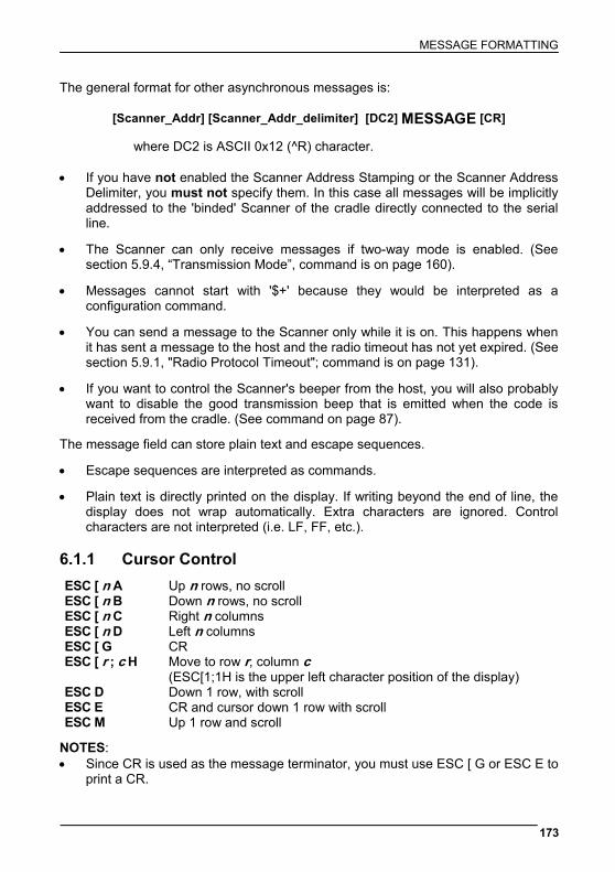
MESSAGE FORMATTING
173
The general format for other asynchronous messages is:
[Scanner_Addr] [Scanner_Addr_delimiter] [DC2] MESSAGE [CR]
where DC2 is ASCII 0x12 (^R) character. • If you have not enabled the Scanner Address Stamping or the Scanner Address
Delimiter, you must not specify them. In this case all messages will be implicitly addressed to the 'binded' Scanner of the cradle directly connected to the serial line.
• The Scanner can only receive messages if two-way mode is enabled. (See section 5.9.4, “Transmission Mode”, command is on page 160).
• Messages cannot start with '$+' because they would be interpreted as a configuration command.
• You can send a message to the Scanner only while it is on. This happens when it has sent a message to the host and the radio timeout has not yet expired. (See section 5.9.1, "Radio Protocol Timeout"; command is on page 131).
• If you want to control the Scanner's beeper from the host, you will also probably want to disable the good transmission beep that is emitted when the code is received from the cradle. (See command on page 87).
The message field can store plain text and escape sequences.
• Escape sequences are interpreted as commands.
• Plain text is directly printed on the display. If writing beyond the end of line, the display does not wrap automatically. Extra characters are ignored. Control characters are not interpreted (i.e. LF, FF, etc.).
6.1.1 Cursor Control ESC [ n A Up n rows, no scroll ESC [ n B Down n rows, no scroll ESC [ n C Right n columns ESC [ n D Left n columns ESC [ G CR ESC [ r ; c H Move to row r, column c
(ESC[1;1H is the upper left character position of the display) ESC D Down 1 row, with scroll ESC E CR and cursor down 1 row with scroll ESC M Up 1 row and scroll
NOTES: • Since CR is used as the message terminator, you must use ESC [ G or ESC E to
print a CR.
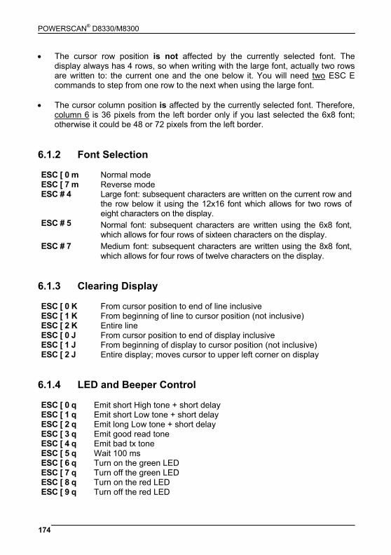
POWERSCAN® D8330/M8300
174
• The cursor row position is not affected by the currently selected font. The display always has 4 rows, so when writing with the large font, actually two rows are written to: the current one and the one below it. You will need two ESC E commands to step from one row to the next when using the large font.
• The cursor column position is affected by the currently selected font. Therefore,
column 6 is 36 pixels from the left border only if you last selected the 6x8 font; otherwise it could be 48 or 72 pixels from the left border.
6.1.2 Font Selection ESC [ 0 m Normal mode ESC [ 7 m Reverse mode ESC # 4 Large font: subsequent characters are written on the current row and
the row below it using the 12x16 font which allows for two rows of eight characters on the display.
ESC # 5 Normal font: subsequent characters are written using the 6x8 font, which allows for four rows of sixteen characters on the display.
ESC # 7 Medium font: subsequent characters are written using the 8x8 font, which allows for four rows of twelve characters on the display.
6.1.3 Clearing Display ESC [ 0 K From cursor position to end of line inclusive ESC [ 1 K From beginning of line to cursor position (not inclusive) ESC [ 2 K Entire line ESC [ 0 J From cursor position to end of display inclusive ESC [ 1 J From beginning of display to cursor position (not inclusive) ESC [ 2 J Entire display; moves cursor to upper left corner on display
6.1.4 LED and Beeper Control ESC [ 0 q Emit short High tone + short delay ESC [ 1 q Emit short Low tone + short delay ESC [ 2 q Emit long Low tone + short delay ESC [ 3 q Emit good read tone ESC [ 4 q Emit bad tx tone ESC [ 5 q Wait 100 ms ESC [ 6 q Turn on the green LED ESC [ 7 q Turn off the green LED ESC [ 8 q Turn on the red LED ESC [ 9 q Turn off the red LED
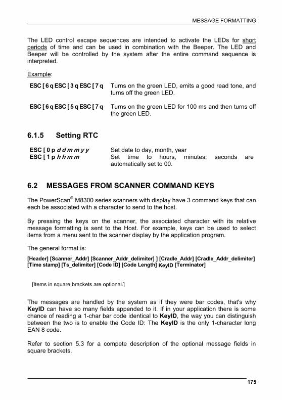
MESSAGE FORMATTING
175
The LED control escape sequences are intended to activate the LEDs for short periods of time and can be used in combination with the Beeper. The LED and Beeper will be controlled by the system after the entire command sequence is interpreted. Example: ESC [ 6 q ESC [ 3 q ESC [ 7 q Turns on the green LED, emits a good read tone, and
turns off the green LED. ESC [ 6 q ESC [ 5 q ESC [ 7 q Turns on the green LED for 100 ms and then turns off
the green LED. 6.1.5 Setting RTC ESC [ 0 p d d m m y y Set date to day, month, year ESC [ 1 p h h m m Set time to hours, minutes; seconds are
automatically set to 00. 6.2 MESSAGES FROM SCANNER COMMAND KEYS The PowerScan® M8300 series scanners with display have 3 command keys that can each be associated with a character to send to the host. By pressing the keys on the scanner, the associated character with its relative message formatting is sent to the Host. For example, keys can be used to select items from a menu sent to the scanner display by the application program. The general format is:
[Header] [Scanner_Addr] [Scanner_Addr_delimiter] ] [Cradle_Addr] [Cradle_Addr_delimiter] [Time stamp] [Ts_delimiter] [Code ID] [Code Length] KeyID [Terminator]
[Items in square brackets are optional.]
The messages are handled by the system as if they were bar codes, that's why KeyID can have so many fields appended to it. If in your application there is some chance of reading a 1-char bar code identical to KeyID, the way you can distinguish between the two is to enable the Code ID: The KeyID is the only 1-character long EAN 8 code. Refer to section 5.3 for a compete description of the optional message fields in square brackets.

POWERSCAN® D8330/M8300
176
The default characters associated with each key (KeyID) are shown in the following table:
Default Key Identifiers
Key KeyID
▲ (left) Key '<' ENTER (center) Key '='
▼ (right) Key '>'
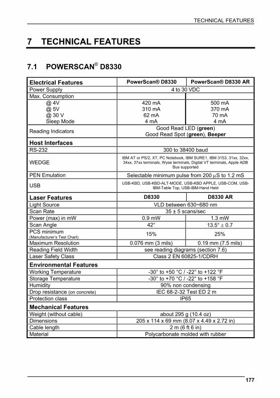
TECHNICAL FEATURES
177
7 TECHNICAL FEATURES 7.1 POWERSCAN® D8330 Electrical Features PowerScan® D8330 PowerScan® D8330 AR Power Supply 4 to 30 VDC Max. Consumption
@ 4V @ 5V @ 30 V Sleep Mode
420 mA 310 mA 62 mA 4 mA
500 mA 370 mA 70 mA 4 mA
Reading Indicators Good Read LED (green) Good Read Spot (green), Beeper
Host Interfaces RS-232 300 to 38400 baud
WEDGE IBM AT or PS/2, XT, PC Notebook, IBM SURE1, IBM 3153, 31xx, 32xx, 34xx, 37xx terminals, Wyse terminals, Digital VT terminals, Apple ADB
Bus supported PEN Emulation Selectable minimum pulse from 200 μS to 1.2 mS
USB USB-KBD, USB-KBD-ALT-MODE, USB-KBD APPLE, USB-COM, USB-IBM-Table Top, USB-IBM-Hand Held
Laser Features D8330 D8330 AR Light Source VLD between 630~680 nm Scan Rate 35 ± 5 scans/sec Power (max) in mW 0.9 mW 1.3 mW Scan Angle 42° 13.5° ± 0.7 PCS minimum (Manufacturer’s Test Chart) 15% 25%
Maximum Resolution 0.076 mm (3 mils) 0.19 mm (7.5 mils) Reading Field Width see reading diagrams (section 7.6) Laser Safety Class Class 2 EN 60825-1/CDRH Environmental Features Working Temperature -30° to +50 °C / -22° to +122 °F Storage Temperature -30° to +70 °C / -22° to +158 °F Humidity 90% non condensing Drop resistance (on concrete) IEC 68-2-32 Test ED 2 m Protection class IP65 Mechanical Features Weight (without cable) about 295 g (10.4 oz) Dimensions 205 x 114 x 69 mm (8.07 x 4.49 x 2.72 in) Cable length 2 m (6 ft 6 in) Material Polycarbonate molded with rubber
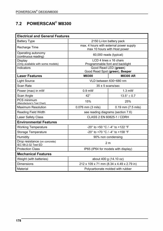
POWERSCAN® D8330/M8300
178
7.2 POWERSCAN® M8300 Electrical and General Features Battery Type 2150 Li-Ion battery pack
Recharge Time max. 4 hours with external power supply max 10 hours with Host power
Operating autonomy (continuous reading) 60,000 reads (typical)
Display (Only available with some models)
LCD 4 lines x 16 chars Programmable font and backlight
Indicators Good Read LED (green) Good Read Spot (green), Beeper
Laser Features M8300 M8300 AR Light Source VLD between 630~680 nm Scan Rate 35 ± 5 scans/sec Power (max) in mW 0.9 mW 1.3 mW Scan Angle 42° 13.5° ± 0.7 PCS minimum (Manufacturer’s Test Chart) 15% 25%
Maximum Resolution 0.076 mm (3 mils) 0.19 mm (7.5 mils) Reading Field Width see reading diagrams (section 7.6) Laser Safety Class CLASS 2 EN 60825-1 / CDRH Environmental Features Working Temperature -20° to +50 °C / -4° to +122 °F Storage Temperature -20° to +70 °C / -4° to +158 °F Humidity 90% non condensing Drop resistance (on concrete) IEC 68-2-32 Test ED 2 m
Protection Class IP65 (IP64 for models with display)
Mechanical Features Weight (with batteries) about 400 g (14.10 oz) Dimensions 212 x 109 x 71 mm (8.34 x 4.49 x 2.79 in) Material Polycarbonate molded with rubber
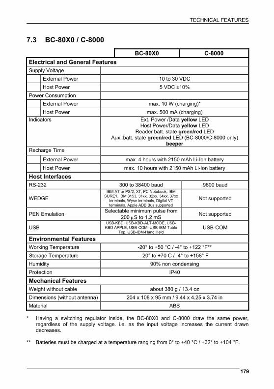
TECHNICAL FEATURES
179
7.3 BC-80X0 / C-8000
BC-80X0 C-8000 Electrical and General Features Supply Voltage External Power 10 to 30 VDC Host Power 5 VDC ±10% Power Consumption External Power max. 10 W (charging)* Host Power max. 500 mA (charging) Indicators Ext. Power /Data yellow LED
Host Power/Data yellow LED Reader batt. state green/red LED
Aux. batt. state green/red LED (BC-8000/C-8000 only) beeper
Recharge Time External Power max. 4 hours with 2150 mAh Li-Ion battery Host Power max. 10 hours with 2150 mAh Li-Ion battery Host Interfaces RS-232 300 to 38400 baud 9600 baud
WEDGE IBM AT or PS/2, XT, PC Notebook, IBM
SURE1, IBM 3153, 31xx, 32xx, 34xx, 37xx terminals, Wyse terminals, Digital VT terminals, Apple ADB Bus supported
Not supported
PEN Emulation Selectable minimum pulse from 200 μS to 1.2 mS Not supported
USB USB-KBD, USB-KBD-ALT-MODE, USB-KBD APPLE, USB-COM, USB-IBM-Table
Top, USB-IBM-Hand Held USB-COM
Environmental Features Working Temperature -20° to +50 °C / -4° to +122 °F** Storage Temperature -20° to +70 C / -4° to +158° F Humidity 90% non condensing Protection IP40 Mechanical Features Weight without cable about 380 g / 13.4 oz Dimensions (without antenna) 204 x 108 x 95 mm / 9.44 x 4.25 x 3.74 in Material ABS
* Having a switching regulator inside, the BC-80X0 and C-8000 draw the same power,
regardless of the supply voltage. i.e. as the input voltage increases the current drawn decreases.
** Batteries must be charged at a temperature ranging from 0° to +40 °C / +32° to +104 °F.
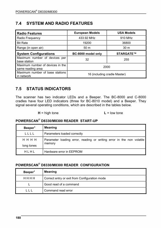
POWERSCAN® D8330/M8300
180
7.4 SYSTEM AND RADIO FEATURES Radio Features European Models USA Models Radio Frequency 433.92 MHz 910 MHz Bit Rate 19200 36800 Range (in open air) 50 m 30 m
System Configurations BC-8000 model only STARGATE™ Maximum number of devices per base station 32 255
Maximum number of devices in the same reading area 2000
Maximum number of base stations in network 16 (including cradle Master)
7.5 STATUS INDICATORS The scanner has two indicator LEDs and a Beeper. The BC-8000 and C-8000 cradles have four LED indicators (three for BC-8010 model) and a Beeper. They signal several operating conditions, which are described in the tables below.
H = high tone L = low tone POWERSCAN® D8330/M8300 READER START-UP
Beeper¹ Meaning
L L L L Parameters loaded correctly
H H H H
long tones
Parameter loading error, reading or writing error in the non volatile memory
H L H L Hardware error in EEPROM
POWERSCAN® D8330/M8300 READER CONFIGURATION
Beeper¹ Meaning
H H H H Correct entry or exit from Configuration mode
L Good read of a command
L L L Command read error
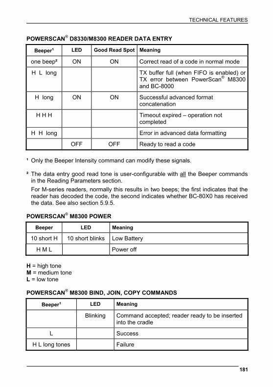
TECHNICAL FEATURES
181
POWERSCAN® D8330/M8300 READER DATA ENTRY
Beeper¹ LED Good Read Spot Meaning
one beep² ON ON Correct read of a code in normal mode
H L long TX buffer full (when FIFO is enabled) or TX error between PowerScan® M8300 and BC-8000
H long ON ON Successful advanced format concatenation
H H H Timeout expired – operation not completed
H H long Error in advanced data formatting
OFF OFF Ready to read a code ¹ Only the Beeper Intensity command can modify these signals. ² The data entry good read tone is user-configurable with all the Beeper commands
in the Reading Parameters section. For M-series readers, normally this results in two beeps; the first indicates that the
reader has decoded the code, the second indicates whether BC-80X0 has received the data. See also section 5.9.5.
POWERSCAN® M8300 POWER
Beeper LED Meaning
10 short H 10 short blinks Low Battery
H M L Power off H = high tone M = medium tone L = low tone POWERSCAN® M8300 BIND, JOIN, COPY COMMANDS
Beeper¹ LED Meaning
Blinking Command accepted; reader ready to be inserted into the cradle
L Success
H L long tones Failure
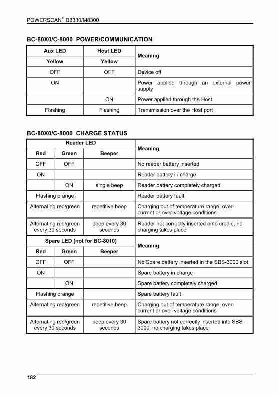
POWERSCAN® D8330/M8300
182
BC-80X0/C-8000 POWER/COMMUNICATION
Aux LED Host LED
Yellow Yellow Meaning
OFF OFF Device off
ON Power applied through an external power supply
ON Power applied through the Host
Flashing Flashing Transmission over the Host port
BC-80X0/C-8000 CHARGE STATUS
Reader LED
Red Green Beeper Meaning
OFF OFF No reader battery inserted
ON Reader battery in charge
ON single beep Reader battery completely charged
Flashing orange Reader battery fault
Alternating red/green repetitive beep Charging out of temperature range, over-current or over-voltage conditions
Alternating red/green every 30 seconds
beep every 30 seconds
Reader not correctly inserted onto cradle, no charging takes place
Spare LED (not for BC-8010)
Red Green Beeper Meaning
OFF OFF No Spare battery inserted in the SBS-3000 slot
ON Spare battery in charge
ON Spare battery completely charged
Flashing orange Spare battery fault
Alternating red/green repetitive beep Charging out of temperature range, over-current or over-voltage conditions
Alternating red/green every 30 seconds
beep every 30 seconds
Spare battery not correctly inserted into SBS-3000, no charging takes place
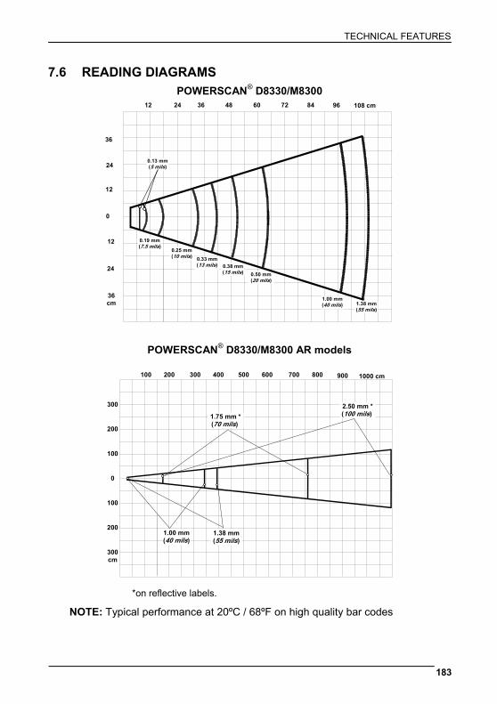
TECHNICAL FEATURES
183
7.6 READING DIAGRAMS
POWERSCAN® D8330/M8300 12 24 36 48 60 96
36
24
12
0
12
24
36 cm
72 84 108 cm
0.19 mm (7.5 mils)
0.25 mm(10 mils) 0.33 mm
(13 mils)
0.50 mm(20 mils)
1.00 mm(40 mils) 1.38 mm
(55 mils)
0.13 mm (5 mils)
0.38 mm(15 mils)
POWERSCAN® D8330/M8300 AR models
100 200 300 400 500 800
100
600 700
1.00 mm(40 mils)
1.38 mm(55 mils)
1.75 mm *(70 mils)
0
200
300
100
200
300 cm
1000 cm900
2.50 mm *(100 mils)
*on reflective labels.
NOTE: Typical performance at 20ºC / 68ºF on high quality bar codes
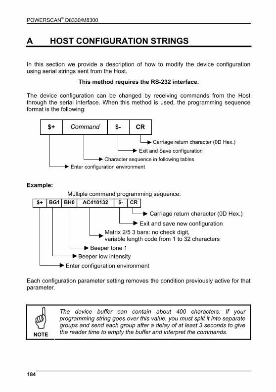
POWERSCAN® D8330/M8300
184
A HOST CONFIGURATION STRINGS In this section we provide a description of how to modify the device configuration using serial strings sent from the Host.
This method requires the RS-232 interface.
The device configuration can be changed by receiving commands from the Host through the serial interface. When this method is used, the programming sequence format is the following:
Command
Character sequence in following tables
CR$-$+
Carriage return character (0D Hex.)
Enter configuration environment
Exit and Save configuration
Example:
Beeper tone 1Beeper low intensity
BG1 $- CR
Carriage return character (0D Hex.)
Exit and save new configuration
AC410132BH0
Matrix 2/5 3 bars: no check digit,variable length code from 1 to 32 characters
$+
Enter configuration environment
Multiple command programming sequence:
Each configuration parameter setting removes the condition previously active for that parameter.
NOTE
The device buffer can contain about 400 characters. If your programming string goes over this value, you must split it into separate groups and send each group after a delay of at least 3 seconds to give the reader time to empty the buffer and interpret the commands.
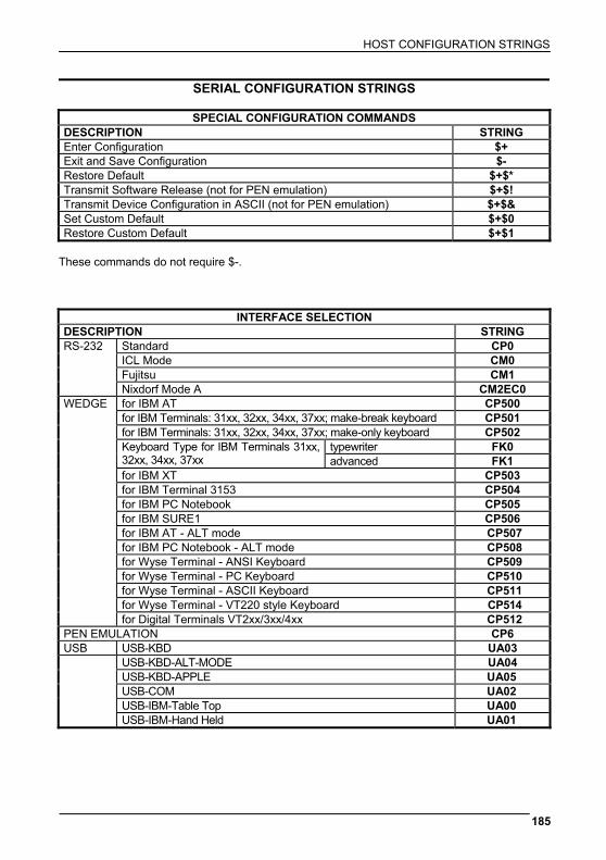
HOST CONFIGURATION STRINGS
185
SERIAL CONFIGURATION STRINGS
SPECIAL CONFIGURATION COMMANDS DESCRIPTION STRING Enter Configuration $+ Exit and Save Configuration $- Restore Default $+$* Transmit Software Release (not for PEN emulation) $+$! Transmit Device Configuration in ASCII (not for PEN emulation) $+$& Set Custom Default $+$0 Restore Custom Default $+$1
These commands do not require $-.
INTERFACE SELECTION DESCRIPTION STRING RS-232 Standard CP0 ICL Mode CM0 Fujitsu CM1 Nixdorf Mode A CM2EC0 WEDGE for IBM AT CP500 for IBM Terminals: 31xx, 32xx, 34xx, 37xx; make-break keyboard CP501 for IBM Terminals: 31xx, 32xx, 34xx, 37xx; make-only keyboard CP502 typewriter FK0
Keyboard Type for IBM Terminals 31xx, 32xx, 34xx, 37xx advanced FK1
for IBM XT CP503 for IBM Terminal 3153 CP504 for IBM PC Notebook CP505 for IBM SURE1 CP506 for IBM AT - ALT mode CP507 for IBM PC Notebook - ALT mode CP508 for Wyse Terminal - ANSI Keyboard CP509 for Wyse Terminal - PC Keyboard CP510 for Wyse Terminal - ASCII Keyboard CP511 for Wyse Terminal - VT220 style Keyboard CP514 for Digital Terminals VT2xx/3xx/4xx CP512 PEN EMULATION CP6 USB USB-KBD UA03 USB-KBD-ALT-MODE UA04 USB-KBD-APPLE UA05 USB-COM UA02 USB-IBM-Table Top UA00 USB-IBM-Hand Held UA01
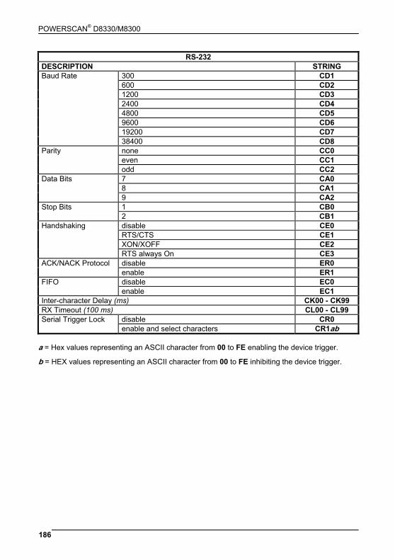
POWERSCAN® D8330/M8300
186
RS-232 DESCRIPTION STRING Baud Rate 300 CD1 600 CD2 1200 CD3 2400 CD4 4800 CD5 9600 CD6 19200 CD7 38400 CD8 Parity none CC0 even CC1 odd CC2 Data Bits 7 CA0 8 CA1 9 CA2 Stop Bits 1 CB0 2 CB1 Handshaking disable CE0 RTS/CTS CE1 XON/XOFF CE2 RTS always On CE3 ACK/NACK Protocol disable ER0 enable ER1 FIFO disable EC0 enable EC1 Inter-character Delay (ms) CK00 - CK99 RX Timeout (100 ms) CL00 - CL99
disable CR0 Serial Trigger Lock enable and select characters CR1ab
a = Hex values representing an ASCII character from 00 to FE enabling the device trigger.
b = HEX values representing an ASCII character from 00 to FE inhibiting the device trigger.
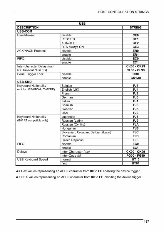
HOST CONFIGURATION STRINGS
187
USB DESCRIPTION STRING USB-COM Handshaking disable CE0 RTS/CTS CE1 XON/XOFF CE2 RTS always ON CE3 ACK/NACK Protocol disable ER0 enable ER1 FIFO disable EC0 enable EC1 Inter-character Delay (ms) CK00 - CK99 RX Timeout (100 ms) CL00 - CL99 Serial Trigger Lock disable CR0 enable CR1ab USB-KBD Keyboard Nationality Belgian FJ7 (not for USB-KBD-ALT-MODE) English (UK) FJ4 French FJ2 German FJ3 Italian FJ1 Spanish FJ6 Swedish FJ5 USA FJ0 Keyboard Nationality Japanese FJ8 (IBM AT compatible only) Russian (Latin) FJ9 Russian (Cyrillic) FJA Hungarian FJB Slovenian, Croatian, Serbian (Latin) FJC Romanian FJD Czech Republic FJE FIFO disable EC0 enable EC1 Delays Inter-Character (ms) CK00 - CK99 Inter-Code (s) FG00 - FG99 USB Keyboard Speed normal UT10 fast UT01
a = Hex values representing an ASCII character from 00 to FE enabling the device trigger.
b = HEX values representing an ASCII character from 00 to FE inhibiting the device trigger.
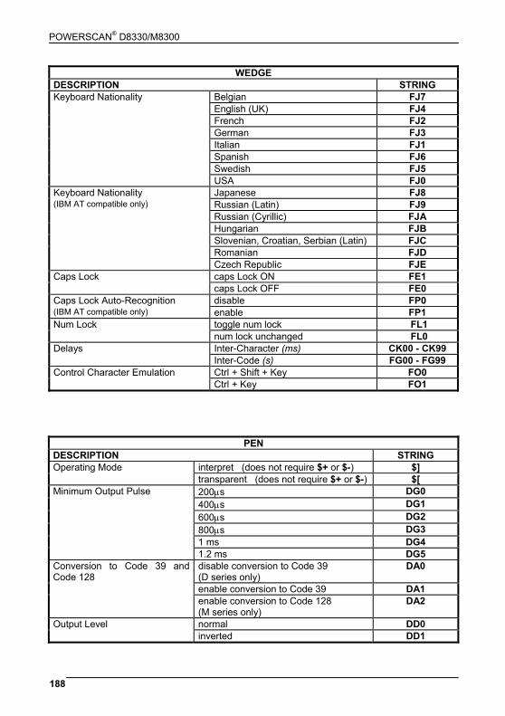
POWERSCAN® D8330/M8300
188
WEDGE DESCRIPTION STRING Keyboard Nationality Belgian FJ7 English (UK) FJ4 French FJ2 German FJ3 Italian FJ1 Spanish FJ6 Swedish FJ5 USA FJ0 Keyboard Nationality Japanese FJ8 (IBM AT compatible only) Russian (Latin) FJ9 Russian (Cyrillic) FJA Hungarian FJB Slovenian, Croatian, Serbian (Latin) FJC Romanian FJD Czech Republic FJE Caps Lock caps Lock ON FE1 caps Lock OFF FE0 Caps Lock Auto-Recognition disable FP0 (IBM AT compatible only) enable FP1 Num Lock toggle num lock FL1 num lock unchanged FL0
Inter-Character (ms) CK00 - CK99 Delays Inter-Code (s) FG00 - FG99
Control Character Emulation Ctrl + Shift + Key FO0 Ctrl + Key FO1
PEN DESCRIPTION STRING Operating Mode interpret (does not require $+ or $-) $] transparent (does not require $+ or $-) $[ Minimum Output Pulse 200μs DG0 400μs DG1 600μs DG2 800μs DG3 1 ms DG4 1.2 ms DG5 Conversion to Code 39 and Code 128
disable conversion to Code 39 (D series only)
DA0
enable conversion to Code 39 DA1 enable conversion to Code 128
(M series only) DA2
Output Level normal DD0 inverted DD1
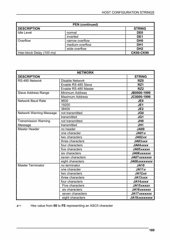
HOST CONFIGURATION STRINGS
189
PEN (continued) DESCRIPTION STRING Idle Level normal DE0 inverted DE1 Overflow narrow overflow DH0 medium overflow DH1 wide overflow DH2 Inter-block Delay (100 ms) CK00-CK99
NETWORK DESCRIPTION STRING RS-485 Network Disable Network RZ0 Enable RS-485 Slave RZ1 Enable RS-485 Master RZ2 Slave Address Range Minimum Address JB0000-1999 Maximum Address JC0000-1999 Network Baud Rate 9600 JE0 19200 JE1 38400 JE2 Network Warning Message not transmitted JG0 transmitted JG1 Transmission Warning not transmitted JH0 Message transmitted JH1 Master Header no header JA00 one character JA01x two characters JA02xx three characters JA03xxx four characters JA04xxxx five characters JA05xxxxx six characters JA06xxxxxx seven characters JA07xxxxxxx eight characters JA08xxxxxxxx Master Terminator no terminator JA10 one character JA11x two characters JA12xx three characters JA13xxx four characters JA14xxxx Five characters JA15xxxxx six characters JA16xxxxxx seven characters JA17xxxxxxx eight characters JA18xxxxxxxx
x = Hex value from 00 to FE representing an ASCII character
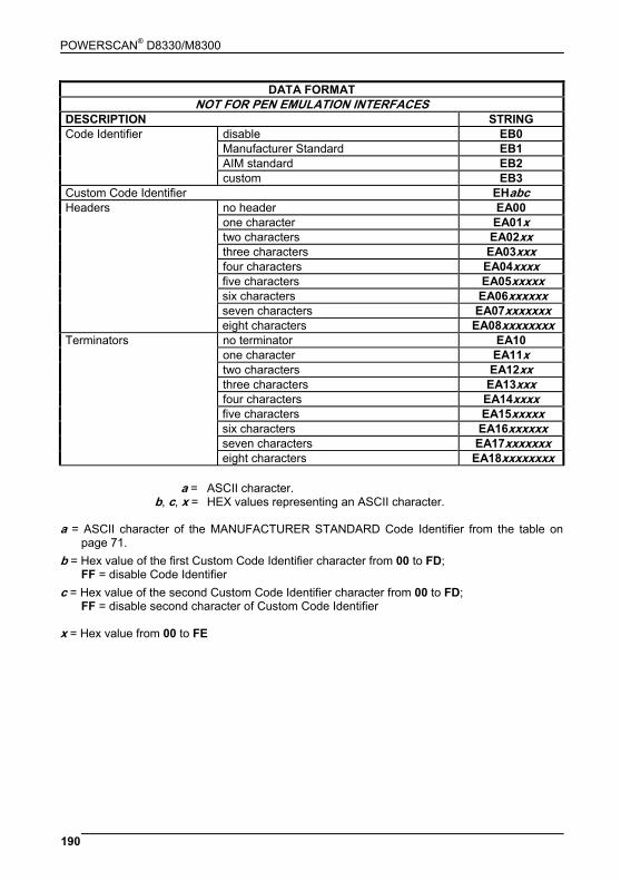
POWERSCAN® D8330/M8300
190
DATA FORMAT NOT FOR PEN EMULATION INTERFACES
DESCRIPTION STRING Code Identifier disable EB0 Manufacturer Standard EB1 AIM standard EB2 custom EB3 Custom Code Identifier EHabc Headers no header EA00 one character EA01x two characters EA02xx three characters EA03xxx four characters EA04xxxx five characters EA05xxxxx six characters EA06xxxxxx seven characters EA07xxxxxxx eight characters EA08xxxxxxxx Terminators no terminator EA10 one character EA11x two characters EA12xx three characters EA13xxx four characters EA14xxxx five characters EA15xxxxx six characters EA16xxxxxx seven characters EA17xxxxxxx eight characters EA18xxxxxxxx
a = ASCII character. b, c, x = HEX values representing an ASCII character. a = ASCII character of the MANUFACTURER STANDARD Code Identifier from the table on
page 71. b = Hex value of the first Custom Code Identifier character from 00 to FD;
FF = disable Code Identifier c = Hex value of the second Custom Code Identifier character from 00 to FD;
FF = disable second character of Custom Code Identifier
x = Hex value from 00 to FE

HOST CONFIGURATION STRINGS
191
DATA FORMAT (continued) NOT FOR PEN EMULATION INTERFACES
DESCRIPTION STRING Code Length Tx not transmitted EE0 transmitted in variable-digit format EE1 transmitted in fixed 4-digit format EE2 Field Adjustment disable EF0
right addition EFa0d left addition EFa1d right deletion EFa2d left deletion EFa3d Field Adjustment Character EGe Character Replacement disable character replacement EO0
first character replacement EO1afg second character replacement EO2afg third character replacement EO3afg Address Stamping disable reader address stamping RU0 enable reader address stamping RU1 disable cradle address stamping RW0 enable cradle address stamping RW1
disable reader address delimiter RV0 Address Delimiter enable reader address delimiter and select character
RV1h
disable cradle address delimiter RY0 enable cradle address delimiter and select
character RY1h
Time Stamping disable IL0 hour/minutes/seconds/month/day/year IL1 hour/minutes/seconds/day/month/year IL2 hour/minutes/seconds IL3 month/day/year IL4 day/month/year IL5 Time Stamping Delimiter disable time stamping delimiter IM0 enable time stamping delimiter and select
character IM1h
a = ASCII character. d = a number from the Hex/Numeric Table e, f, g, h = HEX values representing an ASCII character a = ASCII character of the MANUFACTURER STANDARD Code Identifier from the table on
page 71. d = a number in the range 01-32 from the Hex/Numeric Table e = Hex value from 00 to FE f = Hex value of the character to be replaced from 00 to FE g = Hex value of the new character to insert from 00 to FE
FF = replace with no new character (remove character)
h = a HEX value in the range from 00 - FE representing the ASCII character.
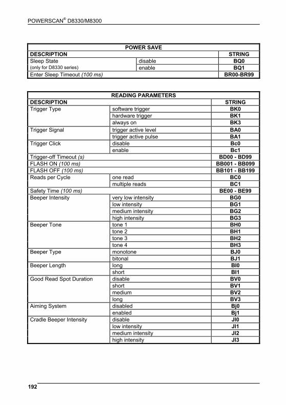
POWERSCAN® D8330/M8300
192
POWER SAVE
DESCRIPTION STRING Sleep State disable BQ0 (only for D8330 series) enable BQ1 Enter Sleep Timeout (100 ms) BR00-BR99
READING PARAMETERS DESCRIPTION STRING Trigger Type software trigger BK0 hardware trigger BK1 always on BK3 Trigger Signal trigger active level BA0 trigger active pulse BA1 Trigger Click disable Bc0 enable Bc1 Trigger-off Timeout (s) BD00 - BD99 FLASH ON (100 ms) BB001 - BB099 FLASH OFF (100 ms) BB101 - BB199 Reads per Cycle one read BC0 multiple reads BC1 Safety Time (100 ms) BE00 - BE99 Beeper Intensity very low intensity BG0 low intensity BG1 medium intensity BG2 high intensity BG3 Beeper Tone tone 1 BH0 tone 2 BH1 tone 3 BH2 tone 4 BH3 Beeper Type monotone BJ0 bitonal BJ1 Beeper Length long BI0 short BI1 Good Read Spot Duration disable BV0 short BV1 medium BV2 long BV3 Aiming System disabled Bj0 enabled Bj1 Cradle Beeper Intensity disable JI0 low intensity JI1 medium intensity JI2 high intensity JI3

HOST CONFIGURATION STRINGS
193
DECODING PARAMETERS DESCRIPTION STRING Ink-spread disable AX0 enable AX1 Overflow Control disable AW1 enable AW0 Interdigit Control disable AV0 enable AV1 Puzzle SolverTM disable AU0 enable AU1 Decoding Safety one read ED0 two reads ED1 three reads ED2 four reads ED3
CODE SELECTION DESCRIPTION STRING DISABLE ALL FAMILY CODES AZ0 EAN/UPC disable EAN/UPC family AA0 EAN 8/EAN 13/UPC A/UPC E without ADD ON AA1 with ADD ON AA5 with and without ADD ON AA8 EAN 8/EAN 13 without ADD ON AA3 with ADD ON 2 ONLY AAK with ADD ON 5 ONLY AAL with ADD ON 2 AND 5 AA6 UPC A/UPC E without ADD ON AA4 with ADD ON 2 ONLY AAM with ADD ON 5 ONLY AAN with ADD ON 2 AND 5 AA7 EAN/UPC with and without Add On no Autodiscrimination AA8Ad0 EAN/UPC Autodiscrimination Add On by Prefix AA8Ad1 Select Prefixes cancel all selections ET0 378/379 ET1378ET2379 434/439 ET3434ET4439 414/419 ET5414ET6419 977 ET7977 978 ET8978 979 ET9979 EAN 8 check digit transmission disable AAG0 enable AAG1 EAN 13 check digit transmission disable AAH0 enable AAH1
CODE SELECTION (continued)
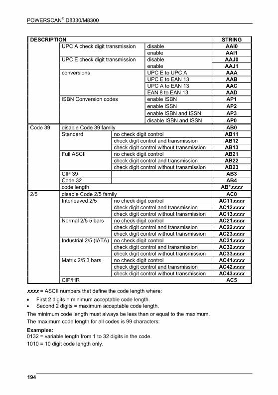
POWERSCAN® D8330/M8300
194
DESCRIPTION STRING UPC A check digit transmission disable AAI0 enable AAI1 UPC E check digit transmission disable AAJ0 enable AAJ1 conversions UPC E to UPC A AAA UPC E to EAN 13 AAB UPC A to EAN 13 AAC EAN 8 to EAN 13 AAD
enable ISBN AP1 enable ISSN AP2 enable ISBN and ISSN AP3
ISBN Conversion codes
disable ISBN and ISSN AP0 Code 39 disable Code 39 family AB0 Standard no check digit control AB11 check digit control and transmission AB12 check digit control without transmission AB13 Full ASCII no check digit control AB21 check digit control and transmission AB22 check digit control without transmission AB23 CIP 39 AB3 Code 32 AB4 code length AB*xxxx 2/5 disable Code 2/5 family AC0 Interleaved 2/5 no check digit control AC11xxxx check digit control and transmission AC12xxxx check digit control without transmission AC13xxxx Normal 2/5 5 bars no check digit control AC21xxxx check digit control and transmission AC22xxxx check digit control without transmission AC23xxxx Industrial 2/5 (IATA) no check digit control AC31xxxx check digit control and transmission AC32xxxx check digit control without transmission AC33xxxx Matrix 2/5 3 bars no check digit control AC41xxxx check digit control and transmission AC42xxxx check digit control without transmission AC43xxxx CIP/HR AC5
xxxx = ASCII numbers that define the code length where: • First 2 digits = minimum acceptable code length. • Second 2 digits = maximum acceptable code length. The minimum code length must always be less than or equal to the maximum. The maximum code length for all codes is 99 characters: Examples: 0132 = variable length from 1 to 32 digits in the code. 1010 = 10 digit code length only.

HOST CONFIGURATION STRINGS
195
CODE SELECTION (continued) DESCRIPTION STRING Codabar disable Codabar family AD0 Standard no start/stop character equality control
nor transmission AD111
no start/stop character equality control but transmission
AD112
start/stop character equality control but no transmission
AD121
start/stop character equality control and transmission
AD122
ABC Codabar no start/stop character equality control but transmission
AD212
Codabar ABC forced concatenation AD232 code length AD*xxxx start/stop character case in transmission lower case ADA0 upper case ADA1 Code 128 disable Code 128 family AI0 enable Code 128 - control without transmission of check digit AI11 enable EAN 128 - control without transmission of check digit AI21 disable EQ0
Transmit GS before Code enable EQ1
ISBT 128 enable ISBT 128 AI31 code length AILxxxx Code 93 disable Code 93 family AK0 enable Code 93 - control without transmission of check digit AK1 MSI disable the family AE0 no check AE1 MOD10 no tx AE2 MOD10 with tx AE3 MOD11-MOD10 no tx AE4 MOD11-MOD10 with tx AE5 MOD10-MOD10 no tx AE6 MOD10-MOD10 with tx AE7
xxxx = ASCII numbers that define the code length where: • First 2 digits = minimum acceptable code length. • Second 2 digits = maximum acceptable code length. The minimum code length must always be less than or equal to the maximum. The maximum code length for all codes is 99 characters: EXAMPLES: 0132 = variable length from 1 to 32 digits in the code. 1010 = 10 digit code length only.
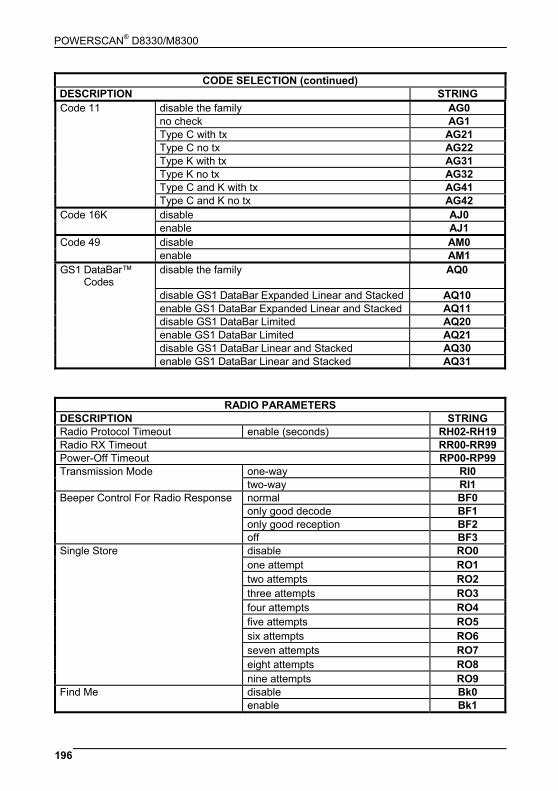
POWERSCAN® D8330/M8300
196
CODE SELECTION (continued) DESCRIPTION STRING Code 11 disable the family AG0 no check AG1 Type C with tx AG21 Type C no tx AG22 Type K with tx AG31 Type K no tx AG32 Type C and K with tx AG41 Type C and K no tx AG42 Code 16K disable AJ0 enable AJ1 Code 49 disable AM0 enable AM1 GS1 DataBar™
Codes disable the family AQ0
disable GS1 DataBar Expanded Linear and Stacked AQ10 enable GS1 DataBar Expanded Linear and Stacked AQ11 disable GS1 DataBar Limited AQ20 enable GS1 DataBar Limited AQ21 disable GS1 DataBar Linear and Stacked AQ30 enable GS1 DataBar Linear and Stacked AQ31
RADIO PARAMETERS DESCRIPTION STRING Radio Protocol Timeout enable (seconds) RH02-RH19 Radio RX Timeout RR00-RR99 Power-Off Timeout RP00-RP99
one-way RI0 Transmission Mode two-way RI1 normal BF0 only good decode BF1 only good reception BF2
Beeper Control For Radio Response
off BF3 disable RO0 one attempt RO1 two attempts RO2 three attempts RO3 four attempts RO4 five attempts RO5 six attempts RO6 seven attempts RO7 eight attempts RO8
Single Store
nine attempts RO9 disable Bk0 Find Me enable Bk1
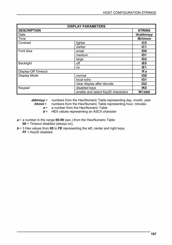
HOST CONFIGURATION STRINGS
197
DISPLAY PARAMETERS DESCRIPTION STRING Date IAddmmyy Time IBhhmm
lighter IC0 Contrast darker IC1 small ID0 medium ID1
Font Size
large ID2 off IE0 Backlight on IE1
Display-Off Timeout IFa normal IG0 local echo IG1
Display Mode
clear display after decode IG2 disabled keys IK0 Keypad enable and select KeyID characters IK1bbb
ddmmyy = numbers from the Hex/Numeric Table representing day, month, year hhmm = numbers from the Hex/Numeric Table representing hour, minutes a = a number from the Hex/Numeric Table b = HEX values representing an ASCII character a = a number in the range 00-99 (sec.) from the Hex/Numeric Table 00 = Timeout disabled (always on). b = 3 Hex values from 00 to FE representing the left, center and right keys. FF = KeyID disabled.
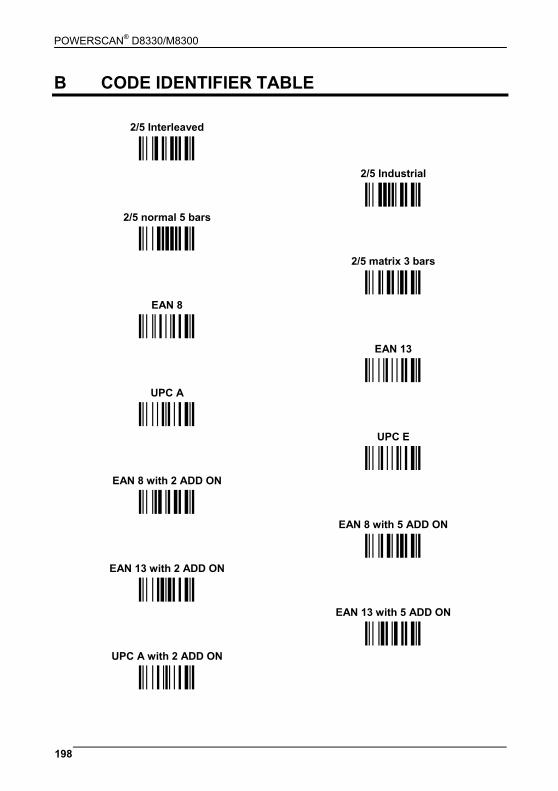
POWERSCAN® D8330/M8300
198
B CODE IDENTIFIER TABLE
2/5 Interleaved
ÌNOÎ 2/5 Industrial
2/5 normal 5 bars ÌPQÎ
ÌOPÎ 2/5 matrix 3 bars
EAN 8 ÌQRÎ
ÌABÎ EAN 13
UPC A ÌBCÎ
ÌCDÎ UPC E
EAN 8 with 2 ADD ON ÌDEÎ
ÌJKÎ EAN 8 with 5 ADD ON
EAN 13 with 2 ADD ON ÌKLÎ
ÌLMÎ EAN 13 with 5 ADD ON
UPC A with 2 ADD ON ÌMNÎ
ÌFGÎ
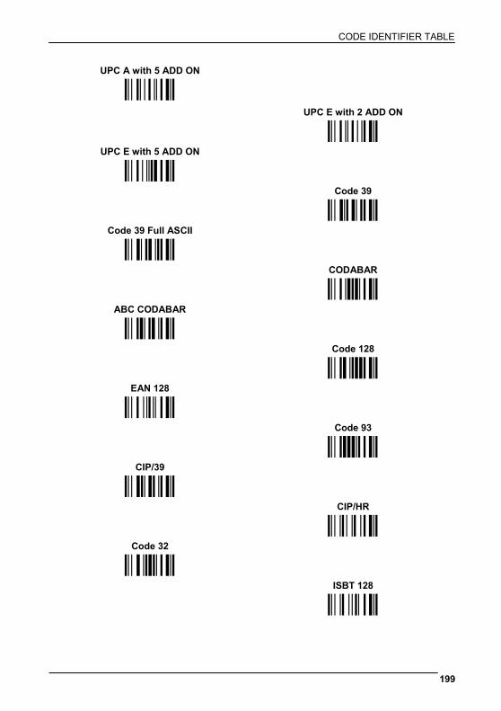
CODE IDENTIFIER TABLE
199
UPC A with 5 ADD ON
ÌGHÎ UPC E with 2 ADD ON
UPC E with 5 ADD ON ÌHIÎ
ÌIJÎ Code 39
Code 39 Full ASCII ÌVWÎ
ÌWXÎ CODABAR
ABC CODABAR ÌRSÎ
ÌSTÎ Code 128
EAN 128 ÌTUÎ
ÌklÎ Code 93
CIP/39 ÌUVÎ
ÌYZÎ CIP/HR
Code 32 ÌefÎ
ÌXYÎ ISBT 128
ÌfgÎ
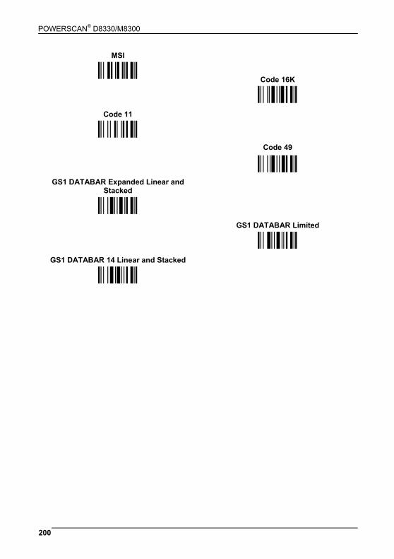
POWERSCAN® D8330/M8300
200
MSI
ÌZ[Î Code 16K
Code 11
ÌpqÎ
ÌbcÎ Code 49
GS1 DATABAR Expanded Linear and Stacked
ÌqrÎ
ÌtuÎ GS1 DATABAR Limited
GS1 DATABAR 14 Linear and Stacked
ÌvwÎ
ÌuvÎ
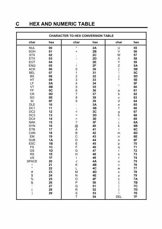
C HEX AND NUMERIC TABLE
CHARACTER TO HEX CONVERSION TABLE
char hex char hex char hex
NUL 00 * 2A U 55 SOH 01 + 2B V 56 STX 02 , 2C W 57 ETX 03 - 2D X 58 EOT 04 . 2E Y 59 ENQ 05 / 2F Z 5A ACK 06 0 30 [ 5B BEL 07 1 31 \ 5C BS 08 2 32 ] 5D HT 09 3 33 ^ 5E LF 0A 4 34 _ 5F VT 0B 5 35 ` 60 FF 0C 6 36 a 61 CR 0D 7 37 b 62 SO 0E 8 38 c 63 SI 0F 9 39 d 64
DLE 10 : 3A e 65 DC1 11 ; 3B f 66 DC2 12 < 3C g 67 DC3 13 = 3D h 68 DC4 14 > 3E i 69 NAK 15 ? 3F j 6A SYN 16 @ 40 k 6B ETB 17 A 41 l 6C CAN 18 B 42 m 6D EM 19 C 43 n 6E SUB 1A D 44 o 6F ESC 1B E 45 p 70 FS 1C F 46 q 71 GS 1D G 47 r 72 RS 1E H 48 s 73 US 1F I 49 t 74
SPACE 20 J 4A u 75 ! 21 K 4B v 76 " 22 L 4C w 77 # 23 M 4D x 78 $ 24 N 4E y 79 % 25 O 4F z 7A & 26 P 50 { 7B ' 27 Q 51 | 7C ( 28 R 52 } 7D ) 29 S 53 ~ 7E T 54 DEL 7F
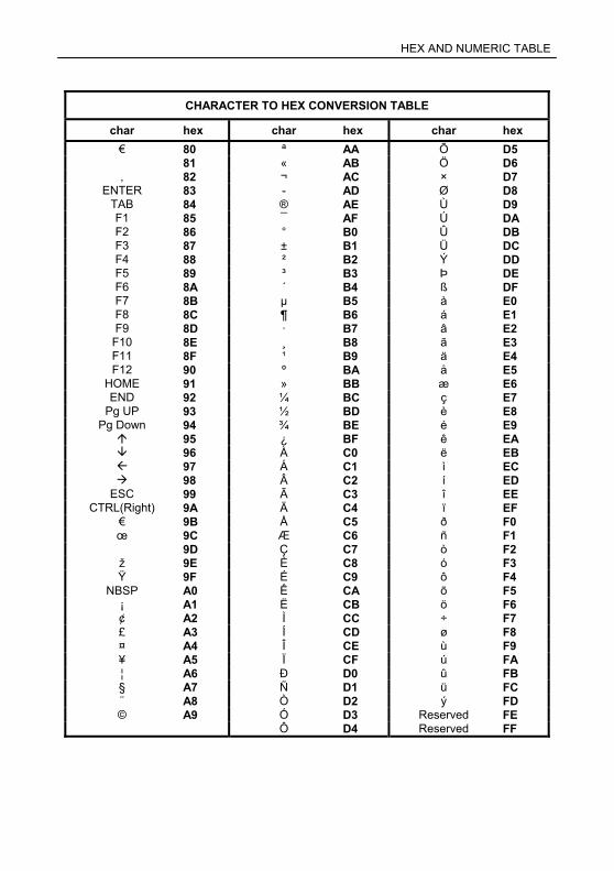
HEX AND NUMERIC TABLE
HEX / NUMERIC TABLE
CHARACTER TO HEX CONVERSION TABLE
char hex char hex char hex € 80 ª AA Õ D5 � 81 « AB Ö D6 ‚ 82 ¬ AC × D7
ENTER 83 - AD Ø D8 TAB 84 ® AE Ù D9 F1 85 ¯ AF Ú DA F2 86 ° B0 Û DB F3 87 ± B1 Ü DC F4 88 ² B2 Ý DD F5 89 ³ B3 Þ DE F6 8A ´ B4 ß DF F7 8B µ B5 à E0 F8 8C ¶ B6 á E1 F9 8D · B7 â E2
F10 8E ¸ B8 ã E3 F11 8F ¹ B9 ä E4 F12 90 º BA å E5
HOME 91 » BB æ E6 END 92 ¼ BC ç E7
Pg UP 93 ½ BD è E8 Pg Down 94 ¾ BE é E9
95 ¿ BF ê EA 96 À C0 ë EB 97 Á C1 ì EC 98 Â C2 í ED
ESC 99 Ã C3 î EE CTRL(Right) 9A Ä C4 ï EF
€ 9B Å C5 ð F0 œ 9C Æ C6 ñ F1 � 9D Ç C7 ò F2 ž 9E È C8 ó F3 Ÿ 9F É C9 ô F4
NBSP A0 Ê CA õ F5 ¡ A1 Ë CB ö F6 ¢ A2 Ì CC ÷ F7 £ A3 Í CD ø F8 ¤ A4 Î CE ù F9 ¥ A5 Ï CF ú FA ¦ A6 Ð D0 û FB § A7 Ñ D1 ü FC ¨ A8 Ò D2 ý FD © A9 Ó D3 Reserved FE Ô D4 Reserved FF
Ì01Î
0 Ì12Î
Ì23Î
1
2 Ì34Î
Ì45Î
3
4 Ì56Î
Ì67Î
5
6 Ì78Î
Ì89Î
7
8 Ì9:Î
ÌABÎ
9
A ÌBCÎ
ÌCDÎ
B
C ÌDEÎ
ÌEFÎ
D
E ÌFGÎ
F
Backspace
Ì$%/Î Cancels an incomplete configuration sequence
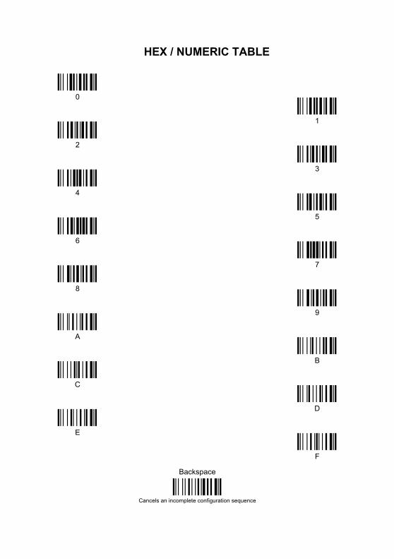