Protocol Converter for CNC Machines FBR-100AN User's Manual · 1. Introduction 1 1. Introduction...
120
Protocol Converter for CNC Machines FBR-100AN User's Manual WA105390XX
Transcript of Protocol Converter for CNC Machines FBR-100AN User's Manual · 1. Introduction 1 1. Introduction...

Protocol Converter for CNC MachinesFBR-100AN
User's Manual
WA105390XX

Copyright© 2019 silex technology, Inc. All rights reserved.
Index
1. Introduction ........................................................................................................1
1-1. Introduction ...........................................................................................................................................1
Disclaimers ..............................................................................................................................................1
Trademarks .............................................................................................................................................1
1-2. Safety Instructions ...............................................................................................................................2
1-3. Product Information and Customer Services .............................................................................7
Product Information ............................................................................................................................7
Customer Support Center .................................................................................................................7
2. Specifications .....................................................................................................9
2-1. Features ................................................................................................................................................. 10
2-2. Parts and Functions .......................................................................................................................... 11
2-3. Hardware Specifications ................................................................................................................. 13
LED (Case Top) .................................................................................................................................... 14
DC Connector ..................................................................................................................................... 16
LED (Network Port) ........................................................................................................................... 17
DIP Switch ............................................................................................................................................ 18
Digital Input ........................................................................................................................................ 19
Serial Port ............................................................................................................................................. 20
2-4. Software Specifications ................................................................................................................... 21
2-5. Wireless Specifications .................................................................................................................... 23
2-6. Regulatory Compliance ................................................................................................................... 25
2-7. Use of Radio Waves ........................................................................................................................... 27
Notes on Usage .................................................................................................................................. 27
2-8. Notes on Security .............................................................................................................................. 29
3. How to Configure FBR-100AN ................................................................... 31
3-1. Sample Connections ........................................................................................................................ 32
Individual Networks (Edge Mode) ............................................................................................... 32
Bridged Network (Bridge Mode) .................................................................................................. 33
3-2. Before You Begin ................................................................................................................................ 34
3-2-1. Necessary Items (Only for Initial Configuration) ............................................................ 34
Necessary Items ................................................................................................................................. 34
Power ON ............................................................................................................................................. 34
Changing Network Setting of PC ................................................................................................ 35
3-2-2. Displaying FBR-100AN's Web Page ..................................................................................... 36
3-3. Basic Configuration ........................................................................................................................... 38
3-4. Using FBR-100AN as Wireless Station......................................................................................... 41
3-4-1. Connecting Access Point by Using 'Easy Configuration' ............................................. 42
3-4-2. Connecting Access Point by Using 'Detailed Configuration' ..................................... 45
IEEE802.1X Authentication ............................................................................................................ 47
3-5. Using AMC Manager to Configure .............................................................................................. 49
3-6. Installing and Using FBR-100AN .................................................................................................. 50
4. List of Functions ............................................................................................. 51
4-1. Showing System Status ................................................................................................................... 52
4-2. Showing Wireless LAN(STA) Status .............................................................................................. 53
4-3. Showing MTConnect Status .......................................................................................................... 54
4-4. Using MTConnect .............................................................................................................................. 55
4-4-1. What is MTConnect? ................................................................................................................. 55
MTConnect Agent and Adapter ................................................................................................... 56
Data Collection Method .................................................................................................................. 57
4-4-2. MTConnect Setting ................................................................................................................... 58
4-4-3. Checking Collected Machine Tool Data ............................................................................ 61
List of HTTP Requests ...................................................................................................................... 61
Sample of MTConnect Client Utility ........................................................................................... 63
4-5. FTP Setting ........................................................................................................................................... 64
4-6. Time Setting ........................................................................................................................................ 66
4-7. Serial Setting ....................................................................................................................................... 68
4-8. Login Password Change .................................................................................................................. 70
4-9. IP Address Filter .................................................................................................................................. 72
4-10. MAC Address Filter ......................................................................................................................... 75

4-11. Log Output ........................................................................................................................................ 77
5. Maintenance Feature .................................................................................... 79
5-1. Factory Default Configuration ...................................................................................................... 80
5-1-1. Factory Default Configuration Using Web Page ............................................................ 80
5-1-2. Factory Default Configuration Using Push Switch ........................................................ 82
5-2. Restart ................................................................................................................................................... 83
5-2-1. Restart by Unplugging Cables .............................................................................................. 83
5-2-2. Restart Using Web Page .......................................................................................................... 84
How to Restart FBR-100AN Using Web Page ........................................................................... 84
5-3. Firmware Update ............................................................................................................................... 86
5-3-1. Downloading Latest Firmware ............................................................................................. 86
5-3-2. How to Update Firmware ....................................................................................................... 87
A. Appendix .......................................................................................................... 91
A-1. List of All Settings ............................................................................................................................. 92
A-1-1. Network Configuration ........................................................................................................... 92
General Configuration ..................................................................................................................... 92
Wireless LAN (STA) - Easy Configuration .................................................................................. 96
Wireless LAN (STA) - Detailed Configuration .......................................................................... 97
MTConnect Configuration - Common Configuration ........................................................102
MTConnect Configuration - Individual Configuration .......................................................104
MTConnect Configuration - Collective Configuration .......................................................105
FTP Configuration ...........................................................................................................................107
Time Configuration .........................................................................................................................108
A-1-2. Serial Configuration ...............................................................................................................109
General Configuration ...................................................................................................................109
A-1-3. Security Configuration ..........................................................................................................111
Login Password Configuration ...................................................................................................111
IP Address Filter Configuration ...................................................................................................111
MAC Address Filter Configuration .............................................................................................113

(blank page)

1. Introduction
1
1. Introduction
Thank you for purchasing "FBR-100AN" (hereinafter the "FBR-100AN"), the MTConnect-compatible protocol converter for CNC devices.
Disclaimers
- The unauthorized transfer or copying of the content of this manual, in whole or in part, without prior written consent is expressly prohibited by law.
- The content of this manual is subject to change without notice. - This manual was prepared to accurately match the content of each OS, but the actual
information shown on the computer monitor may differ from the content of this manual due to future OS version upgrades, modifications, and other changes.
- Although every effort was made to prepare this manual with the utmost accuracy, Silex Technology will not be held liable for any damages as a result of errors, setting examples, or other content.
Trademarks
- AMC Manager® is a registered trademark of silex technology. - Microsoft and Windows are registered trademarks of Microsoft Corporation in the United
States and/or other countries. - Wi-Fi, Wi-Fi Protected Setup (WPS), Wi-Fi Protected Access (WPA), WPA2 are trademarks or
registered trademarks of Wi-Fi Alliance. - Other company names and product names contained in this manual are trademarks or
registered trademarks of their respective companies.
1-1. IntroductionThis manual provides information on how to configure and use the FBR-100AN.Please read the 1-2. Safety Instructions carefully before you begin.

2
FBR-100AN User's Manual
1-2. Safety Instructions
This page provides the safety instructions for safe use of FBR-100AN.To ensure safe and proper use, please read the following information carefully before using FBR-100AN.
< Meaning of the warnings >
Danger "DANGER" indicates an imminently hazardous situation that could result in death or serious injury if the safety instruction is not observed.
Warning "Warning" indicates the existence of a hazard that could result in death or serious injury if the safety instruction is not observed.
Caution "Caution" indicates the existence of a hazard that could result in serious injury or material damage if the safety instruction is not observed.
< Meaning of the symbols >
This symbol indicates the warning and caution.( Example: "Danger of the electric shock" )
This symbol indicates the prohibited actions. ( Example: "Disassembly is prohibited" )
This symbol indicates the actions users are required to observe. ( Example: "Remove the AC plug from an outlet" )

1. Introduction
3
Danger
* Do not use this product in a place where flammable gas is generated. It may cause an explosion, fire, electric shock or malfunction.
* Make sure that foreign objects (metal, combustibles, liquids, etc.) do not get into this product. It may cause fire or electric shock.
* Do not install this product in an unstable place or do not stop installation halfway. This product may fall.* If this product is not used according to the given instructions, the protection function
may be lost.* This product is not intended for use in applications requiring high reliability such as
aviation, space, nuclear power, medical equipment, etc..

4
FBR-100AN User's Manual
Warning
* In the following cases, turn off the connected devices and unplug the DC cable or AC plug of this product from a power outlet. Failure to follow these instructions may cause fire or an electrical shock.
- When this product emits a strange smell, smoke or sound or becomes too hot to touch.- When foreign objects (metal, liquid, etc.) gets into this product.- When this product is dropped or the case is broken or cracked.
* Do not disassemble or modify this product. It may cause fire, electrical shock or malfunction.
* Do not disassemble or modify the AC adaptor (sold separately). It may cause fire, electrical shock or malfunction.
* Do not place anything on top of this product. Also, do not place this product on top of the other product. Failure to do so may cause fire, electrical shock, malfunction or performance degradation.
* Do not cover up this product with a cloth such as blanket or table cloth. The heat remains inside and it may cause fire or malfunction.
* Do not place any objects on top of AC adapter or DC cable, or do not cover it up with anything. Also, do not use the AC adapter on top of the heat/moisture retaining materials (carpet, sponge, cardboard, styrofoam, etc.). The accumulated heat may result in fire or malfunction.
* Do not roll up or wrap DC cable or AC cord. It may cause fire or an electrical shock.* Do not plug or unplug AC adaptor or DC cable with wet hands. It may cause an
electrical shock or malfunction.* Do not move this product when AC adapter or DC cable is connected to it. The cable
may be damaged, and which may result in fire or electric shock.
* For use of the devices connected to this product, please follow all warnings, cautions and notices given by that manufacturer and carefully use them in a proper manner. Failure to follow these instructions may cause fire, electrical shock or malfunction.
* Use the correct power voltage. Improper voltage may cause fire or an electrical shock.
* If a ground wire is supplied with your device to use with, connect it to the ground terminal in order to prevent an electrical shock. Do not connect the ground wire to gas pipe, water pipe, lighting rod or telephone ground wire. It may cause malfunction.
* Keep the cords and cables away from children. It may cause an electrical shock or serious injury.
* Make sure that you have a secure scaffold when this product is installed or removed to/from a high place. There is a danger of falling.

1. Introduction
5
Caution
* Use the AC adaptor designated by Silex Technology. Other AC adaptors may cause malfunction.
* Do not place any objects on the cable, pinch the cable between walls and shelves, bend, twist or pull the cord strongly.
* Do not use or store this product under the following conditions. It may cause malfunction.
- Locations subject to vibration or shock- Shaky, uneven or tilted surfaces- Locations exposed to direct sunlight- Humid or dusty places- Wet places (kitchen, bathroom, etc.)- Near a heater or stove- Locations subject to extreme changes in temperature- Near strong electromagnetic sources (magnet, radio, wireless device, etc.)- Poorly ventilated locations (on bookshelf, rack, etc.)- Near chemical substance
* Do not step on this product. The product may be broken and it causes injury.* Do not place the cables in a place where many people walk by. They may trip over
the cables and get injured.* When installing this product to a high position, make sure that this product is firmly
fixed so it does not drop for weight of the cables.* Do not use or store this product in an extremely humid or dusty place. When using
this product in such an environment, please install it on a dust-proof control panel, etc..
* Use this product under the appropriate operating conditions (temperature, humidity, vibration, shock).
* When this product malfunctions or shows abnormal operation, turn off it and contact the point of purchase or Silex Technology's customer support.
* Be sure to use a shield cable to connect the peripheral equipment.* When this product gets dirty, wipe it gently with a soft cloth using water or neutral
detergent. Using volatile solvents (benzene, thinner, etc.) or chemicals may cause peeling or discoloration of the paint.
* When connecting the cables, check the shape of the connectors to make sure they are connected to the right direction.
* Do not touch this product and connectors with wet hands. There is a danger of electric shock.
* When using this product in a place subject to effects of overcurrent or overvoltage (lightning surge, etc.), use the proper surge protection device (SPD) for all connectors (power line, LAN, RS-232C, RS-422A, RS-485, DI, earth, etc.). For selection/installation of SPD, please contact the specialized contractor.
6
FBR-100AN User's Manual
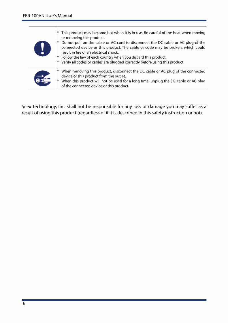
* This product may become hot when it is in use. Be careful of the heat when moving or removing this product.
* Do not pull on the cable or AC cord to disconnect the DC cable or AC plug of the connected device or this product. The cable or code may be broken, which could result in fire or an electrical shock.
* Follow the law of each country when you discard this product.* Verify all codes or cables are plugged correctly before using this product.
* When removing this product, disconnect the DC cable or AC plug of the connected device or this product from the outlet.
* When this product will not be used for a long time, unplug the DC cable or AC plug of the connected device or this product.
Silex Technology, Inc. shall not be responsible for any loss or damage you may suffer as a result of using this product (regardless of if it is described in this safety instruction or not).

1. Introduction
7
1-3. Product Information and Customer Services
- Latest firmware download - Latest software download - Latest manual download - Support information (FAQ)
Customer Support Center
Customer Support is available by e-mail or telephone for any problems that you mayencounter. If you cannot find the relevant problem in this manual or on our website, or if the corrective procedure does not resolve the problem, please contact Silex Technology Customer Support.
- Visit the Silex Technology website (https://www.silextechnology.com/) for the latest FAQ and product information.
Note
Product Information
The services below are available from the Silex Technology website. For details, please visitthe Silex Technology website.
URL
USA / Europe https://www.silextechnology.com/
Contact Information
USA +1-657-218-5199 [email protected]
Europe +49-2154-88967-0 [email protected]

8
FBR-100AN User's Manual
(blank page)

2. Specifications
9
2. Specifications
Connected manufacturingCloud services
Internet
Manufacturing monitoringOn-premises server
Wired or Wireless LAN
Serial + DPRNT Digital input
FANUC CNC equipped
machine tools,
robots, etc.
LAN for information
LAN for equipment
PWR WLAN
NC Serial
DISWCOM 2 1 0 PWR LAN2 LAN1 Serial
DCIN24V
DCIN12V
PWR WLAN
NC Serial
DISWCOM 2 1 0 PWR LAN2 LAN1 Serial
DCIN24V
DCIN12V
PWR WLAN
NC Serial
DISWCOM 2 1 0 PWR LAN2 LAN1 Serial
DCIN24V
DCIN12V
PWR WLAN
NC Serial
DISWCOM 2 1 0 PWR LAN2 LAN1 Serial
DCIN24V
DCIN12V
FANUC CNC equipped
legacy machine tools
CNC Communication + Wired LAN
Connection Image
FBR-100AN is a converter that monitors CNC machine tools and transfers the operating status to the factory monitoring system/server.As the MTConnect communication is supported, which is the standard feature adopted by factory device manufacturers of the United States, CNC machine tools can efficiently be connected to the host system. By using a wired/wireless bridge function, cableless network can be established in a factory where cable wiring is not always easy.
10
FBR-100AN User's Manual
2-1. Features
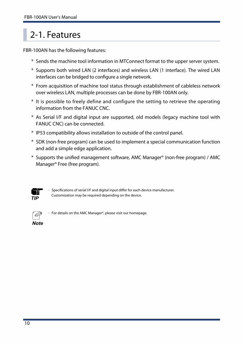
* Sends the machine tool information in MTConnect format to the upper server system.
* Supports both wired LAN (2 interfaces) and wireless LAN (1 interface). The wired LAN interfaces can be bridged to configure a single network.
* From acquisition of machine tool status through establishment of cableless network over wireless LAN, multiple processes can be done by FBR-100AN only.
* It is possible to freely define and configure the setting to retrieve the operating information from the FANUC CNC.
* As Serial I/F and digital input are supported, old models (legacy machine tool with FANUC CNC) can be connected.
* IP53 compatibility allows installation to outside of the control panel.
* SDK (non-free program) can be used to implement a special communication function and add a simple edge application.
* Supports the unified management software, AMC Manager® (non-free program) / AMC Manager® Free (free program).
FBR-100AN has the following features:
- For details on the AMC Manager®, please visit our homepage.
Note
- Specifications of serial I/F and digital input differ for each device manufacturer. Customization may be required depending on the device.TIP

2. Specifications
11
2-2. Parts and Functions
Front
1
4
2
Digital input interface
Push switch
Network port
5 Serial port (RS-232C/422A/485 connector)
6
7
DC connector
DC jack
The parts name and functions are as follows:
1
3
5
6
7
4
2
3 DIP switch

12
FBR-100AN User's Manual
Top
8
9
8
9 Top LED
Antenna

2. Specifications
13
2-3. Hardware SpecificationsHardware Specifications
Wired LAN I/FRJ-45 x 210Base-T / 100Base-TX / 1000Base-T x 2Port (Auto-sensing)AutoMDI/MDIX is supported.
ROM SPI Flash ROM 32MByte
RAM DDR3L SDRAM Memory 256MByte
MMC eMMC 2GByte (Pseudo SLC)
LED
Network portLED x 2
Link LEDStatus LED
: Green: Orange
Top of the unit
LED x 4PWR(Power) LEDWLAN LEDSerial LEDCNC LED
: Red/Green/Orange: Red/Green/Orange: Red/Green/Orange: Red/Green/Orange
Push SwitchPush switch x 1
Dip switch x 4
Antenna Wireless LAN Eternal antenna2.4GHz / 5GHz dual band
Dimension W : 230mm x D : 105mm x H : 36mm (unit size)
EMI VCCI Class-A
PowerDC jack (DC 12Vin ±5%)
DC connector (DC 24Vin ±5%)
Serial I/F RS-232/RS-422/RS-485 (D-Sub 9pin)
Digital Input I/F Photocoupler isolated input x 3
Operating/Storage Environment
Operating environment Temperature : -20℃ to 50℃ Humidity : 20% to 90%RH (Non-condensing)
Storage environmentTemperature : -20℃ to 55℃Humidity : 20% to 90%RH (Non-condensing)
- When wireless LAN is not used, or when a large amount of data is not transmitted or received continuously over wireless LAN (e.g. when only CNC operating status data is transferred), FBR-100AN can withstand the temperature up to 55 degrees.Note
- For RS-485, only the physical interface is supported. To use RS-485, it needs to be added from the firmware.
Note

14
FBR-100AN User's Manual
Status Meaning
Off Off FBR-100AN is powered off.
GreenOn FBR-100AN is powered on.
Blink Firmware update is in progress.
OrangeOn Factory default configuration is in progress
(initialization / eMMC format)
Blink -
Red
On (FBR-100AN is started with a recovery firmware.)
BlinkHardware error- Wireless error- eMMC mount failure
PWR LEDShows the power status and operating status of FBR-100AN.
PWR LEDWLAN LED
Serial LEDCNC LED
LED (Case Top)

2. Specifications
15
Status Meaning
Off Off No serial communication is in progress.
GreenOn RS-232C is operating.
Blink RS-232C is handling data transmission/reception.
OrangeOn RS-422A is operating.
Blink RS-422A is handling data transmission/reception.
RedOn Error status
- Serial communication value error
Blink Data transmission/reception is in progress after the error status occurs.
Serial LED Shows the serial communication status.
WLAN LED Shows the network status.
Status Meaning
Off Off -
GreenOn FBR-100AN is connected to wireless LAN.
(Signal strength: 3, RSSI: -63dBm or higher)
Blink Data communication is in progress.(Signal strength: 3, RSSI: -63dBm or higher)
OrangeOn FBR-100AN is connected to wireless LAN.
(Signal strength: 2, RSSI: -78dBm to -64dBm)
Blink Data communication is in progress.(Signal strength: 2, RSSI: -78dBm to -64dBm)
Red
On FBR-100AN is connected to wireless LAN.(Signal strength: 1, RSSI: -79dBm or lower)
Blink
Data communication is in progress.(Signal strength: 1, RSSI: -79dBm or lower)
Or wireless LAN is enabled but Access Point is not connected.
- To make sure of stable wireless communication, it is recommended to use FBR-100AN in the environment at which the WLAN LED turns green.TIP

16
FBR-100AN User's Manual
Status Meaning
Off Off FBR-100AN is not connected to the CNC device. (IP address is not configured.)
GreenOn FBR-100AN is connected to the CNC device.
(Data collection is completed successfully.)
Blink -
OrangeOn -
Blink -
RedOn Error status
- Data acquisition failure
Blink -
CNC LED Shows the CNC device connection status.
DC Connector
12
PIN Number Signal Name Description
1 DCIN DC 12-24Vin ±5%
2 GND GND
DC connecter : JST S02B-F32SK-GGXR(LF)(AU)
For this connector, please use JST JFA connector 300 series F32FSS-02V-KX.

2. Specifications
17
Status Meaning
GreenOn Wired LAN is linked.
Off Wired LAN is not linked.
Status Meaning
Orange Blink The packet is received from wired LAN.
Link LEDShows the wired LAN link status.
Status LEDShows the wired LAN communication status.
LED (Network Port)
Link LED Status LED
18
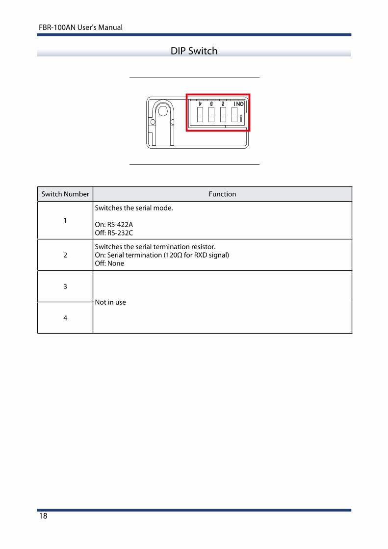
FBR-100AN User's Manual
DIP Switch
Switch Number Function
1
Switches the serial mode.
On: RS-422AOff: RS-232C
2Switches the serial termination resistor.On: Serial termination (120Ω for RXD signal)Off: None
3
Not in use
4

2. Specifications
19
Digital Input
Signal Note
DIN0
Turns ON when the external input is Low, and turns OFF when it is High. DIN1
DIN2
COM+COM-
DIN0
DIN1
DIN2
Input equivalent circuit

20
FBR-100AN User's Manual
Serial Port
PIN Number RS-232 RS-422A/RS-485
1 DCD [in] TxD- [out]
2 RxD [in] TxD+ [out]
3 TxD [out] RxD+ [in]
4 DTR [out] RxD- [in]
5 GND [ - ] GND [ - ]
6 DSR [in] -
7 RTS [out] -
8 CTS [in] -
9 RI [in] -
15
69
2. Specifications
21
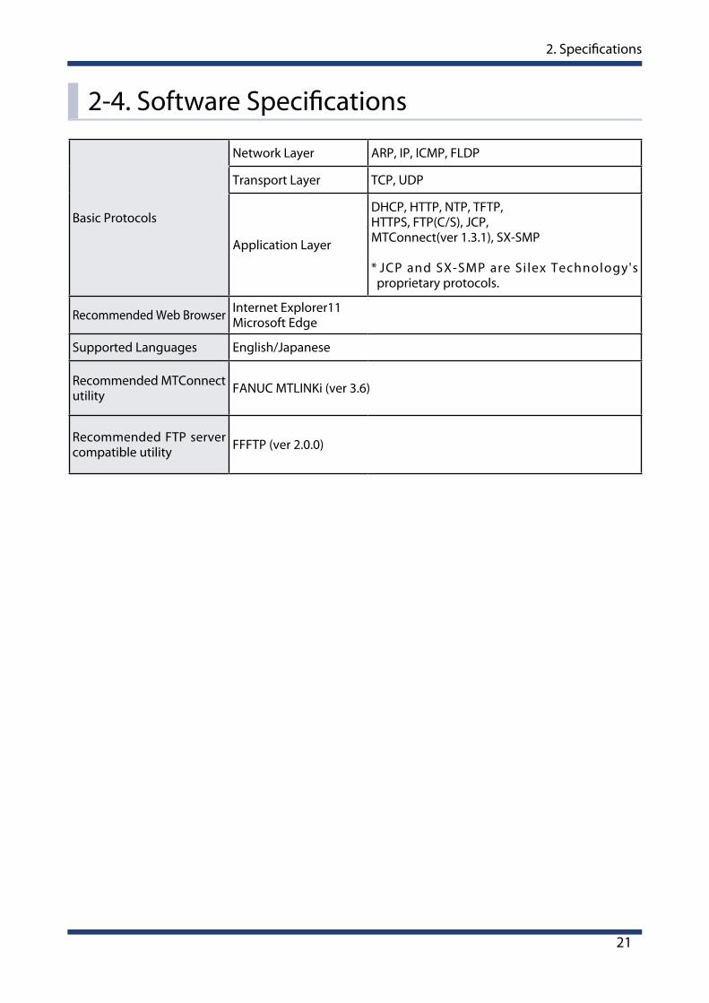
2-4. Software Specifications
Basic Protocols
Network Layer ARP, IP, ICMP, FLDP
Transport Layer TCP, UDP
Application Layer
DHCP, HTTP, NTP, TFTP,HTTPS, FTP(C/S), JCP, MTConnect(ver 1.3.1), SX-SMP
* JCP and SX-SMP are Si lex Technology's proprietary protocols.
Recommended Web Browser Internet Explorer11Microsoft Edge
Supported Languages English/Japanese
Recommended MTConnect utility FANUC MTLINKi (ver 3.6)
Recommended FTP server compatible utility FFFTP (ver 2.0.0)

22
FBR-100AN User's Manual
FANUC CNC Compatible Models
Network compatible
30i-MODEL B31i-MODEL B31i-MODEL B532i-MODEL B35i-Model B
30i-MODEL A31i-MODEL A31i-MODEL A532i-MODEL A
0i-M/T MODEL F0i-M/T MODEL D
* To access the CNC device using FOCAS1/2, the Ethernet function is required.
Serial/DPRNTcompatible
FANUC Series 15FANUC Series 16/18/20/21FANUC Power Mate -D/F/HFANUC Series 16i/18i/21iFANUC Power Mate iFANUC Series 15iFANUC Series 0iFANUC Series 30i/31i/32i
* Depending on the configuration of CNC device or machine tool, DPRNT may not be supported.

2. Specifications
23
2-5. Wireless Specifications
IEEE802.11a
Frequency 5GHz band
Transmission Method OFDM
Transmission Rate 54 / 48 / 36 / 24 / 18 / 12 / 9 / 6 (Mbps)
Channel
[US]W52 : 36, 40, 44, 48W53 : 52, 56, 60, 64W56 : 100, 104, 108, 112, 116, 132, 136, 140W58 : 149, 153, 157, 161, 165
[EU]W52 : 36, 40, 44, 48W53 : 52, 56, 60, 64W56 : 100, 104, 108, 112, 116, 120, 124, 128, 132, 136, 140
IEEE802.11b
Frequency 2.4GHz band
Transmission Method DS-SS
Transmission Rate 11 / 5.5 / 2 / 1 (Mbps)
Channel [US]1-11ch [EU]1-13ch
IEEE802.11g
Frequency 2.4GHz band
Transmission Method OFDM
Transmission Rate 54 / 48 / 36 / 24 / 18 / 12 / 9 / 6 (Mbps)
Channel [US]1-11ch [EU]1-13ch
IEEE802.11n (5GHz)
Frequency 5GHz band
Transmission Method MIMO-OFDM
Transmission Rate MCS0, 1, 2, 3, 4, 5, 6, 7 (1Stream)MSC8, 9, 10, 11, 12, 13, 14,15 (2Stream)
Channel
[US]W52 : 36, 40, 44, 48W53 : 52, 56, 60, 64W56 : 100, 104, 108, 112, 116, 132, 136, 140W58 : 149, 153, 157, 161, 165
[EU]W52 : 36, 40, 44, 48W53 : 52, 56, 60, 64W56 : 100, 104, 108, 112, 116, 120, 124, 128, 132, 136, 140
Wireless LAN I/F

24
FBR-100AN User's Manual
STA Mode(Wireless Station)
Open (WEP 64/128Bit)Shared (WEP 64/128Bit)WPA2-PSK (AES)WPA/WPA2-PSK (TKIP/AES)WPA2-EAP (AES)WPA/WPA2-EAP (TKIP/AES)
Wireless Security
IEEE802.11n (2.4GHz)
Frequency 2.4GHz band
Transmission Method MIMO-OFDM
Transmission Rate MCS0, 1, 2, 3, 4, 5, 6, 7 (1Stream)MSC8, 9, 10, 11, 12, 13, 14,15 (2Stream)
Channel [US]1-11ch [EU]1-13ch

2. Specifications
25
2-6. Regulatory ComplianceFCC / IC Notice
Note: This equipment has been tested and found to comply with the limits for a Class A digital device, pursuant to part 15 of the FCC Rules. These limits are designed to provide reasonable protection against harmful interference when the equipment is operated in a commercial environment. This equipment generates, uses, and can radiate radio frequency energy and, if not installed and used in accordance with the instruction manual, may cause harmful interference to radio communications. Operation of this equipment in a residential area is likely to cause harmful interference in which case the user will be required to correct the interference at his own expense.
FCC CAUTIONChanges or modifications not expressly approved by the party responsible for compliance could void the user’s authority to operate the equipment.
This device complies with part 15 of the FCC Rules. Operation is subject to the following two conditions:
(1) This device may not cause harmful interference.(2) This device must accept any interference received, including interference that may
cause undesired operation.
CAN ICES-3(A)/NMB-3(A)
This device complies with Industry Canada’s licence-exempt RSSs. Operation is subject to the following two conditions:(1) This device may not cause interference; and(2) This device must accept any interference, including interference that may cause undesired operation of the device.
Le présent appareil est conforme aux CNR d’Industrie Canada applicables aux appareils radio exempts de licence. L’exploitation est autorisée aux deux conditions suivantes :1) l’appareil ne doit pas produire de brouillage;2) l’utilisateur de l’appareil doit accepter tout brouillage radioélectrique subi, même si le brouillage est susceptible d’en compromettre le fonctionnement.

26
FBR-100AN User's Manual
CE Notice

2. Specifications
27
2-7. Use of Radio Waves
Notes on Usage
Do not use FBR-100AN near the following devices or places.
* Microwave, scientific instruments, pacemaker or other medical equipment, etc.* Licensed radio station in a factory * Small power radio station (A non-licensed radio station)
These devices may use the same band. If you use FBR-100AN near these devices, the radio waves emitted from FBR-100AN may interfere with them.
A cellular phone, TV and radio use a different radio band than our products. Generally, if they are used near FBR-100AN, it will not cause any problems. However, when they approximate FBR-100AN, sound or image noise may occur.
Do not use FBR-100AN near a cellular phone, TV or Radio.
If there is reinforced concrete/metal between wireless devices, they may not connect.
FBR-100AN can connect through wood or glass, but may have troubles connecting through reinforced concrete/metal.
FBR-100AN complies with the certification of conformance to technical standards. Please pay attention to the following points:
* Please do not disassemble or remodel the product. Such action is prohibited by law.* Please do not remove the certificate label. Using the product without a label is
prohibited.

28
FBR-100AN User's Manual
DS/OF2.4 4
2.4 : Wireless devices using 2.4GHz frequency bandDS/OF : DS-SS or OFDM is used as modulation.4 : The range of interference is equal to or lower than 40m.
: All bands can be used to avoid interference.
Wireless devices using 2.4GHz band
The same frequency band of FBR-100AN is used for a microwave, industry, science, medical equipment and licensed in room or low power (non-licensed) radio stations.
* Before you use FBR-100AN, check that it does not interfere with other devices. * If interference occurs, stop using FBR-100AN or change the wireless band. Please
consider to create a wall between these devices to avoid interference. Contact us for possible solution.
Notes on using 5GHz band
* Use of 5.2GHz band (W52) and 5.3GHz band (W53) outdoors is prohibited by the radio regulations. Use only W56 channels then.
* The meaning of the symbols in the bottom of the unit:
2. Specifications
29
2-8. Notes on Security
Because a wireless LAN uses electromagnetic signals instead of a network cable to establish communication with network devices, it has the advantage of allowing devices to connect to the network easily. However, a disadvantage of this is that within a certain range, the electromagnetic signals can pass through barriers such as walls, and if security countermeasures are not implemented in some way, problems such as the following may occur.
* Communication is intercepted by a third party* Unauthorized access to the network* Leakage of personal information (ID and Card information)* Spoofing and the falsification of intercepted data* System crashes and data corruption
Nowadays, wireless LAN cards or access points are equipped with security measures that address such security problems, so that you can enable security-related settings for wireless LAN products in order to reduce the likelihood of problems occurring. We recommend that you make yourself fully acquainted with the possible implications of what might happen if you use a wireless product without enabling security features, and that you configure security-related settings and use wireless products at your own responsibility.

30
FBR-100AN User's Manual
(blank page)

3. How to Configure FBR-100AN
31
3. How to Configure FBR-100AN
This chapter explains how to configure FBR-100AN.

32
FBR-100AN User's Manual
3-1. Sample Connections
Wired LAN (2 interfaces) and wireless LAN (1 interfaces) of FBR-100AN can be used separately to configure the individual network. Also, it is possible to bridge the interfaces to configure the combined network. The followings are the sample connections. Configure FBR-400AN appropriately for your environment.
Individual Networks (Edge Mode)
Assign IP address and subnet mask for each interface to configure individual network. In the Edge mode, the operating information can only be retrieved from the machine tools and be transferred to the PC. In the sample connection below, it is impossible to access the machine tools from PC-01 or PC-02.
Local network 3192.168.3.0/24
Local network 2192.168.2.0/24
Local network 1192.168.1.0/24
Machine tool
Ethernet HUBEthernet HUB
PC- 01
PC- 02
FBR-100AN
Wireless Access Point

3. How to Configure FBR-100AN
33
Bridged Network (Bridge Mode)
Two interfaces of wired LAN can be bridged to configure a single network. Wireless LAN will run as a separate network from wired LAN then.In the sample connection below, PC-01 and PC-02 can collect the operating information of machine tool via FBR-100AN. It is impossible to access the machine tool from the PC-02.
- A bridge between wireless/wired interfaces will be supported in the future when the firmware version of FBR-100AN is upgraded.TIP
Local network 2192.168.2.0/24
Local network 1192.168.1.0/24
Machine tool
Ethernet HUBEthernet HUB
PC- 01
PC- 02
FBR-100AN
Wireless Access Point
34
FBR-100AN User's Manual
3-2. Before You Begin
3-2-1. Necessary Items (Only for Initial Configuration)
Necessary Items
The following explains the preparation for configuration.
Following items are required for initial configuration.
PCNetwork cable
Turn on FBR-100AN.Confirm that the PWR LED turns green on top of FBR-100AN.
Power ON
Connect one end of network cable to LAN1 of FBR-100AN and the other end to PC.1.
2.

3. How to Configure FBR-100AN
35
Turn on the PC.3.
(2)
Network cable
PC
AC adapter or DC cable
(1)
Changing Network Setting of PC
The following explains how to modify PC network settings so that you can access FBR-100AN from your PC.
The default IP address of FBR-100AN is 192.168.1.1 (Class C). For the IP address of the PC, configure the different one that is not used by FBR-100AN.
Example) Network settingsSet up the network settings of your PC as follows:IP address : 192.168.1.123Subnet mask : 255.255.255.0

36
FBR-100AN User's Manual
Start the Web browser on the PC.1.
When the login page is displayed, enter the password of FBR-100AN for Password and click Login.
3.
- By default, the login password is not set. Just click Login then.
Note
Enter the IP address of FBR-100AN (xxx.xxx.xxx.xxx) to the address bar.
- The default IP address of FBR-100AN is "192.168.1.1".
2.
Note
- For information on the compatible Web browser, refer to 2-4. Software Specifications.
Note
3-2-2. Displaying FBR-100AN's Web Page
The network settings of FBR-100AN can be configured from its Web configuration interface. By entering the IP address of FBR-100AN to the address bar of your Web browser, the Web configuration page can be accessed.

3. How to Configure FBR-100AN
37
When the Web page is displayed, select the network setting you want to configure from the configuration menu.
4.
Configuration menu Details
Select Language Switches the language between English and Japanese.
Status
System Shows the system information.
Wireless LAN(STA) Shows the wireless station setting. When a wireless interface is disabled, it is not displayed.
MTConnect Shows the MTConnect setting.
Network Conf
General Configure the basic network setting.
Wireless LAN(STA) Configure the setting to use FBR-100AN as a wireless station.
MTConnect Configure the MTConnect setting.
FTP Configure the FTP setting.
Time Configure the time setting.
Serial Conf General Configure the serial setting.
Security Conf
Login Password Login password can be changed.
IP Address Filter The access from the specified device to FBR-100AN can be restricted using the IP address filter.
MAC Address Filter The access from the specified device to FBR-100AN can be restricted using the MAC address filter.
Management Log Output Obtains the system log.
Maintenance
Setting Initialization Executes the factory default configuration and then restarts FBR-100AN.
Restart Restarts FBR-100AN.
Firmware Update Updates the firmware.
Logout Logs out the Web page.
38
FBR-100AN User's Manual
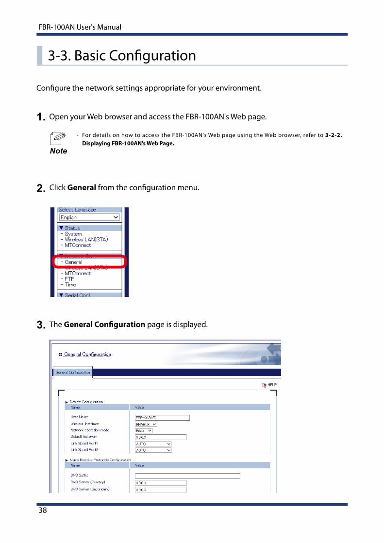
Click General from the configuration menu.2.
The General Configuration page is displayed.3.
3-3. Basic Configuration
Configure the network settings appropriate for your environment.
Open your Web browser and access the FBR-100AN's Web page.
- For details on how to access the FBR-100AN's Web page using the Web browser, refer to 3-2-2. Displaying FBR-100AN's Web Page.
1.
Note

3. How to Configure FBR-100AN
39
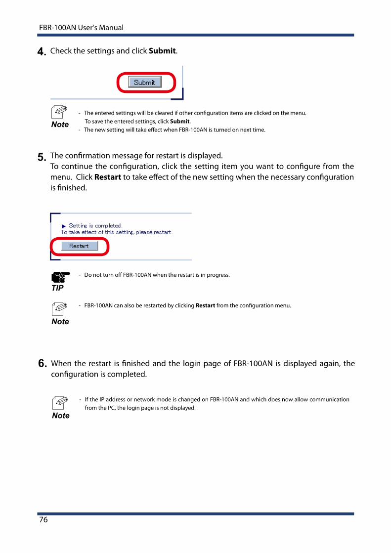
Check the settings and click Submit.4.
- The entered settings will be cleared if other configuration items are clicked on the menu. To save the entered settings, click Submit.
- The new setting will take effect when FBR-100AN is turned on next time.Note
Select the operation mode at Network operation mode appropriately for your environment. The setting items will differ depending on the operation mode you select. Configure each setting which may appear.
- For details on each configuration item, refer to A-1. List of All Settings.
Note
40
FBR-100AN User's Manual
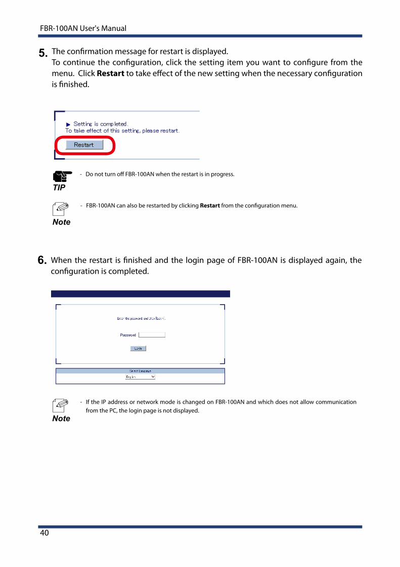
- If the IP address or network mode is changed on FBR-100AN and which does not allow communication from the PC, the login page is not displayed.
Note
- Do not turn off FBR-100AN when the restart is in progress.
TIP
- FBR-100AN can also be restarted by clicking Restart from the configuration menu.
Note
5. The confirmation message for restart is displayed.To continue the configuration, click the setting item you want to configure from the menu. Click Restart to take effect of the new setting when the necessary configuration is finished.
When the restart is finished and the login page of FBR-100AN is displayed again, the configuration is completed.
6.
3. How to Configure FBR-100AN
41
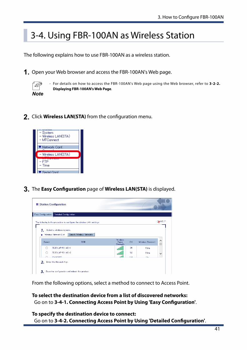
3-4. Using FBR-100AN as Wireless Station
Open your Web browser and access the FBR-100AN's Web page.
- For details on how to access the FBR-100AN's Web page using the Web browser, refer to 3-2-2. Displaying FBR-100AN's Web Page.
Click Wireless LAN(STA) from the configuration menu.
1.
2.
Note
The Easy Configuration page of Wireless LAN(STA) is displayed.3.
The following explains how to use FBR-100AN as a wireless station.
To select the destination device from a list of discovered networks: Go on to 3-4-1. Connecting Access Point by Using 'Easy Configuration'.
To specify the destination device to connect: Go on to 3-4-2. Connecting Access Point by Using 'Detailed Configuration'.
From the following options, select a method to connect to Access Point.

42
FBR-100AN User's Manual
The Easy Configuration page is displayed and wireless networks are detected.2.
Click Wireless LAN(STA) from the configuration menu and click Easy Configuration.1. - When the Easy Configuration page is already displayed, this process is not necessary.
Note
From a list of the discovered wireless networks, select one to connect.
3-4-1. Connecting Access Point by Using 'Easy Configuration'
- When the Access Point has one of the following settings, it cannot be connected using the 'Easy Configuration' feature. Refer to 3-4-2. Connecting Access Point by Using 'Detailed Configuration' then.
- WEP key is used and WEP key index of the Access Point is other than 1.- Network authentication method is set to Shared, WPA2-EAP or WPA/WPA2-EAP.- Stealth function is enabled on the Access Point.
TIP

3. How to Configure FBR-100AN
43
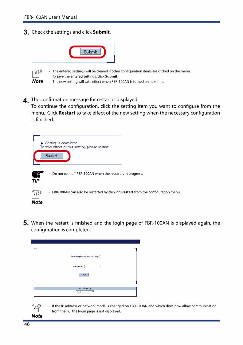
Check the settings and click Submit.4.
- In the wireless network list, up to 32 Access Points are displayed in the order of higher signal strength. - When the network key of the Access Point is already registered to FBR-100AN, such Access Point is
displayed in the top of the list, regardless of the signal strength. - To refresh the wireless network list, click Search Wireless Networks. - When the network authentication method of Access Point is set to WPA-PSK or WPA2-PSK, network
authentication and encryption mode of FBR-100AN are set to WPA/WPA2-PSK and AUTO respectively.
Note
From a list of the discovered wireless networks, select one to connect and then enter the network key.
3.

44
FBR-100AN User's Manual
- Do not turn off FBR-100AN when the restart is in progress.
TIP
- FBR-100AN can also be restarted by clicking Restart from the configuration menu.
Note
5. The confirmation message for restart is displayed.To continue the configuration, click the setting item you want to configure from the menu. Click Restart to take effect of the new setting when the necessary configuration is finished.
When the restart is finished and the login page of FBR-100AN is displayed again, the configuration is completed.
6.
- If the IP address or network mode is changed on FBR-100AN and which does now allow communication from the PC, the login page is not displayed.
Note

3. How to Configure FBR-100AN
45
In the Detailed Configuration page, configure each setting.2.
Click Wireless LAN(STA) from the configuration menu and click Detailed Configuration.1. - When the Detailed Configuration page is already displayed, this process is not necessary.
Note
Configure the setting to connect the Access Point in wireless LAN.
3-4-2. Connecting Access Point by Using 'Detailed Configuration'
- For details on each configuration item, refer to A-1. List of All Settings. - FBR-100AN supports the IEEE802.1X authentication. For information on the compatible authentication
methods and certificates, refer to IEEE802.1X Authentication.Note
46
FBR-100AN User's Manual
Check the settings and click Submit.3.
- The entered settings will be cleared if other configuration items are clicked on the menu. To save the entered settings, click Submit.
- The new setting will take effect when FBR-100AN is turned on next time.Note
- Do not turn off FBR-100AN when the restart is in progress.
TIP
- FBR-100AN can also be restarted by clicking Restart from the configuration menu.
Note
4. The confirmation message for restart is displayed.To continue the configuration, click the setting item you want to configure from the menu. Click Restart to take effect of the new setting when the necessary configuration is finished.
When the restart is finished and the login page of FBR-100AN is displayed again, the configuration is completed.
5.
- If the IP address or network mode is changed on FBR-100AN and which does now allow communication from the PC, the login page is not displayed.
Note
3. How to Configure FBR-100AN
47
IEEE802.1X Authentication
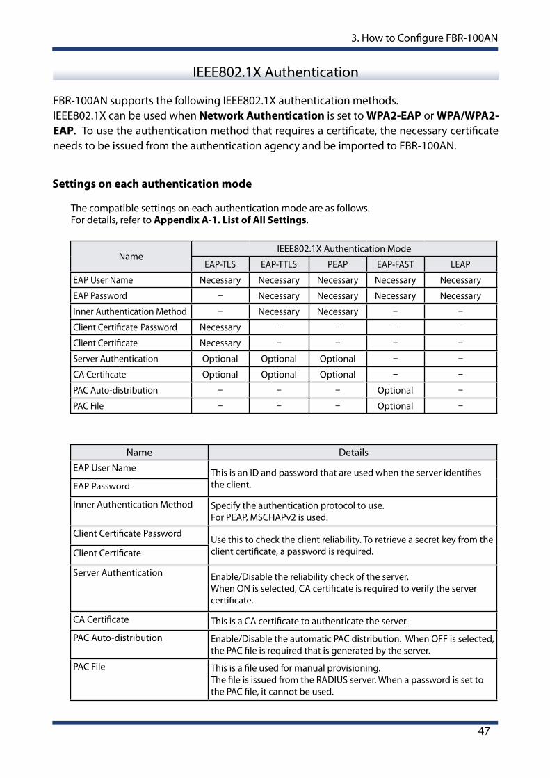
FBR-100AN supports the following IEEE802.1X authentication methods.IEEE802.1X can be used when Network Authentication is set to WPA2-EAP or WPA/WPA2-EAP. To use the authentication method that requires a certificate, the necessary certificate needs to be issued from the authentication agency and be imported to FBR-100AN.
Settings on each authentication mode
The compatible settings on each authentication mode are as follows.For details, refer to Appendix A-1. List of All Settings.
NameIEEE802.1X Authentication Mode
EAP-TLS EAP-TTLS PEAP EAP-FAST LEAP
EAP User Name Necessary Necessary Necessary Necessary Necessary
EAP Password - Necessary Necessary Necessary Necessary
Inner Authentication Method - Necessary Necessary - -
Client Certificate Password Necessary - - - -
Client Certificate Necessary - - - -
Server Authentication Optional Optional Optional - -
CA Certificate Optional Optional Optional - -
PAC Auto-distribution - - - Optional -
PAC File - - - Optional -
Name DetailsEAP User Name This is an ID and password that are used when the server identifies
the client.EAP Password
Inner Authentication Method Specify the authentication protocol to use.For PEAP, MSCHAPv2 is used.
Client Certificate PasswordUse this to check the client reliability. To retrieve a secret key from the client certificate, a password is required.Client Certificate
Server Authentication Enable/Disable the reliability check of the server.When ON is selected, CA certificate is required to verify the server certificate.
CA Certificate This is a CA certificate to authenticate the server.
PAC Auto-distribution Enable/Disable the automatic PAC distribution. When OFF is selected, the PAC file is required that is generated by the server.
PAC File This is a file used for manual provisioning. The file is issued from the RADIUS server. When a password is set to the PAC file, it cannot be used.

48
FBR-100AN User's Manual
Certificate Standard
Certificate Saving Format
The following certificates are supported:
The following saving formats are supported:
Certificate Compatible standards
Client certificate pfx* This is a format that includes a secret key of the certificate.
CA Certificate PEM (A text format in which DER is BASE64 encoded.)
Certificate Item Compatible standardsClient certificate X509 certificate version v3
Public key algorithm RSAPublic key size 512bit, 1024bit, 2048bitSignature algorithm SHA1/SHA2 (SHA-224, SHA-256,
SHA-384, SHA-512) withRSAMD5withRSA
X509v3 extended key usage Client authentication(1.3.6.1.5.5.7.3.2)
CA certificate Public key algorithm RSAPublic key size 512bit, 1024bit, 2048bitSignature algorithm SHA1/SHA2 (SHA-224, SHA-256,
SHA-384, SHA-512) withRSAMD5withRSA

3. How to Configure FBR-100AN
49
3-5. Using AMC Manager to Configure
The FBR-100AN settings can be configured using AMC Manager®.For details on how to use AMC Manager®, see the user's manual of AMC Manager®.
- For details on each configuration item, refer to A-1. List of All Settings
Note

50
FBR-100AN User's Manual
3-6. Installing and Using FBR-100AN
After the configuration is finished, install and fix FBR-100AN in the location of use.For use in wired LAN, connect FBR-100AN to the network using a network cable before turning on it. To fix FBR-100AN to the location of use, you can use either the mounting stays on the product case or the DIN rail mounting plate (commercially available).
- DIN rail and DIN rail mounting plate are not contained in the product package. They need to be purchased separately.
- Recommended DIN rail : TAKACHI DRA-1Note
DIN rail mounting plate(commercially available)
Attach this
DIN rail
Fixing DIN rail mounting plate to FBR-100AN Fixing DIN rail mounting plate to DIN rail

4. List of Functions
51
4. List of Functions
This chapter explains the FBR-100AN functions.
52
FBR-100AN User's Manual
4-1. Showing System Status
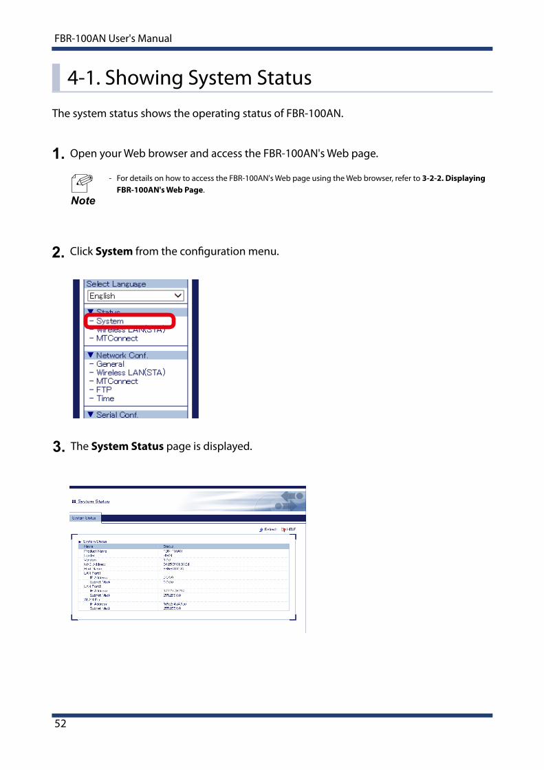
Open your Web browser and access the FBR-100AN's Web page.
- For details on how to access the FBR-100AN's Web page using the Web browser, refer to 3-2-2. Displaying FBR-100AN's Web Page.
Click System from the configuration menu.
The System Status page is displayed.
1.
2.
3.
Note
The system status shows the operating status of FBR-100AN.

4. List of Functions
53
Open your Web browser and access the FBR-100AN's Web page.
- For details on how to access the FBR-100AN's Web page using the Web browser, refer to 3-2-2. Displaying FBR-100AN's Web Page.
- In the configuration menu, Wireless LAN(STA) under Status is not displayed when a wireless LAN interface is not enabled.
Click Wireless LAN(STA) from the configuration menu.
1.
2.
Note
Wireless LAN(STA) status shows the setting of wireless station.
The Station Status page is displayed.3.
4-2. Showing Wireless LAN(STA) Status

54
FBR-100AN User's Manual
Open your Web browser and access the FBR-100AN's Web page.
- For details on how to access the FBR-100AN's Web page using the Web browser, refer to 3-2-2. Displaying FBR-100AN's Web Page.
Click MTConnect from the configuration menu.
1.
2.
Note
MTConnect status shows the MTConnect setting.
The MTConnect Status page is displayed.3.
4-3. Showing MTConnect Status

4. List of Functions
55
4-4. Using MTConnectThe following explains how to collect the CNC data.
4-4-1. What is MTConnect?
- MTConnect is the communication protocol for machine tools, which is standardized by the MTConnect Institution.
- MTConnect uses the open communication interfaces (HTTP/XML). It only supports reading the values from the operating monitor of machine tools and does not support writing the values.
- As FBR-100AN has MTConnect Agent and Adapter features, it can be used from MTConnect-compatible client and agent software.
- MTConnect compatible client software does not come with FBR-100AN. It needs to be purchased separately.
Note

56
FBR-100AN User's Manual
MTConnect Agent and Adapter
FBR-100AN has both MTConnect Agent and Adapter features and can receive the data in XML format or SHDR format (the format with vertical separation lines).
- AgentCollects the data of Adapter.FBR-100AN retrieves the data from Adapter and then replies in XLM format data, when it is accessed by the client software.
- AdapterCollects the data of machine tools.FBR-100AN replies with SHDR format data (the format with vertical separation lines), when it is accessed by the client software.
MTConnectClient
Operationmanagementdatabase
Operationmanagementdatabase
MTConnect client compatiblefactory operation management software
Machine tool 1
MTConnect agent compatiblefactory operation management software
Operation management database
Agent
Agent
Adapter
Agent
Adapter
Agent
Adapter
Machine tool 2
Machine tool 3
Adapter
Machine tool 4
Interface of each CNC machine tool(LAN, serial)
FBR-100AN
FBR-100AN
HTTP/HTTPS(XML)
Adapter Adapter
Adapter compatibleMachine tool 5
Adapter compatibleMachine tool 6
Protocol of each Adapter
TCP(SHDR)
- The operating information of maximum 3 CNC machine tools can be retrieved by FBR-100AN. When the maximum 3 CNC machine tools are used, a part of the reading function is restricted.TIP
4. List of Functions
57
Data Collection Method
There are 3 methods of collecting the machine tool data.
IndividualThe data of each point is individually collected based on the point file imported from the Web page of FBR-100AN.
Collective(Network)The data is collected at once based on the configured PCM information. The collected data is analyzed using the imported device information.* To read the operating information at once using the start/end addresses specified on FBR-100AN, you may need to change the setting of CNC device in advance.
Collective(DPRNT)DPRNT specification data is collected at once from a serial (RS-232C).
Glossary
Term Description
Point file This is the configuration file to specify the information of machine tools as a data point and transfer it by MTConnect.
Device information fileThe device information file is used for collective data collection.It is a file to define the machine tool configuration as MTConnect and analyze the collected data.

58
FBR-100AN User's Manual
4-4-2. MTConnect SettingThe following explains how to configure the MTConnect setting.
Open your Web browser and access the FBR-100AN's Web page.
- For details on how to access the FBR-100AN's Web page using the Web browser, refer to 3-2-2. Displaying FBR-100AN's Web Page.
Click MTConnect from the configuration menu.
The MTConnect Configuration page is displayed.Configure each setting.
1.
2.
3.
Note
To create a file to import, use a point file creation utility or device information creation utility.

4. List of Functions
59
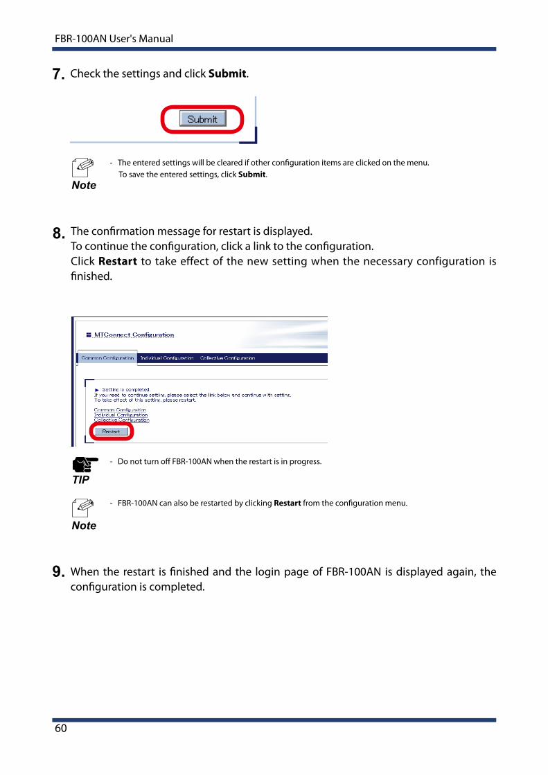
Check the settings and click Submit.4.
- The entered settings will be cleared if other configuration items are clicked on the menu. To save the entered settings, click Submit.
Note
5. Configure the settings appropriately for Data Acquisition Mode you have selected.- For individual collection Click Individual Configuration.
- For collective collection (network) or collective collection (DPRNT) Click Collective Configuration.
6. Configure each setting in the displayed page.
Individual Configuration Collective Configuration
- For details on each configuration item, refer to A-1. List of All Settings.
Note
60
FBR-100AN User's Manual
Check the settings and click Submit.7.
- The entered settings will be cleared if other configuration items are clicked on the menu. To save the entered settings, click Submit.
Note
- Do not turn off FBR-100AN when the restart is in progress.
TIP
- FBR-100AN can also be restarted by clicking Restart from the configuration menu.
Note
8. The confirmation message for restart is displayed.To continue the configuration, click a link to the configuration.Click Restart to take effect of the new setting when the necessary configuration is finished.
When the restart is finished and the login page of FBR-100AN is displayed again, the configuration is completed.
9.
4. List of Functions
61
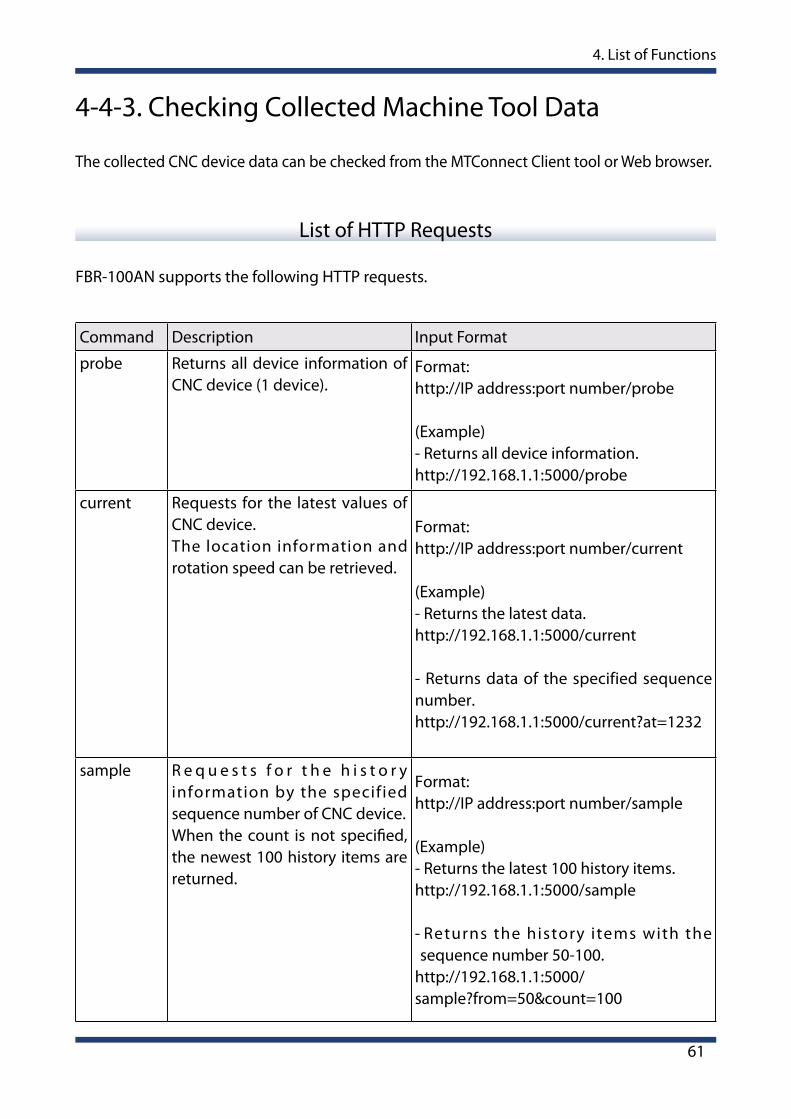
4-4-3. Checking Collected Machine Tool Data
The collected CNC device data can be checked from the MTConnect Client tool or Web browser.
Command Description Input Format
probe Returns all device information of CNC device (1 device).
Format:http://IP address:port number/probe
(Example)- Returns all device information.http://192.168.1.1:5000/probe
current Requests for the latest values of CNC device.The location information and rotation speed can be retrieved.
Format:http://IP address:port number/current
(Example)- Returns the latest data.http://192.168.1.1:5000/current
- Returns data of the specified sequence number.http://192.168.1.1:5000/current?at=1232
sample R e q u e s t s f o r t h e h i s t o r y information by the specified sequence number of CNC device.When the count is not specified, the newest 100 history items are returned.
Format:http://IP address:port number/sample
(Example)- Returns the latest 100 history items.http://192.168.1.1:5000/sample
- Returns the history items with the sequence number 50-100.
http://192.168.1.1:5000/sample?from=50&count=100
FBR-100AN supports the following HTTP requests.
List of HTTP Requests
62
FBR-100AN User's Manual
- "(Double-quote) and space require URL encoding.
TIP
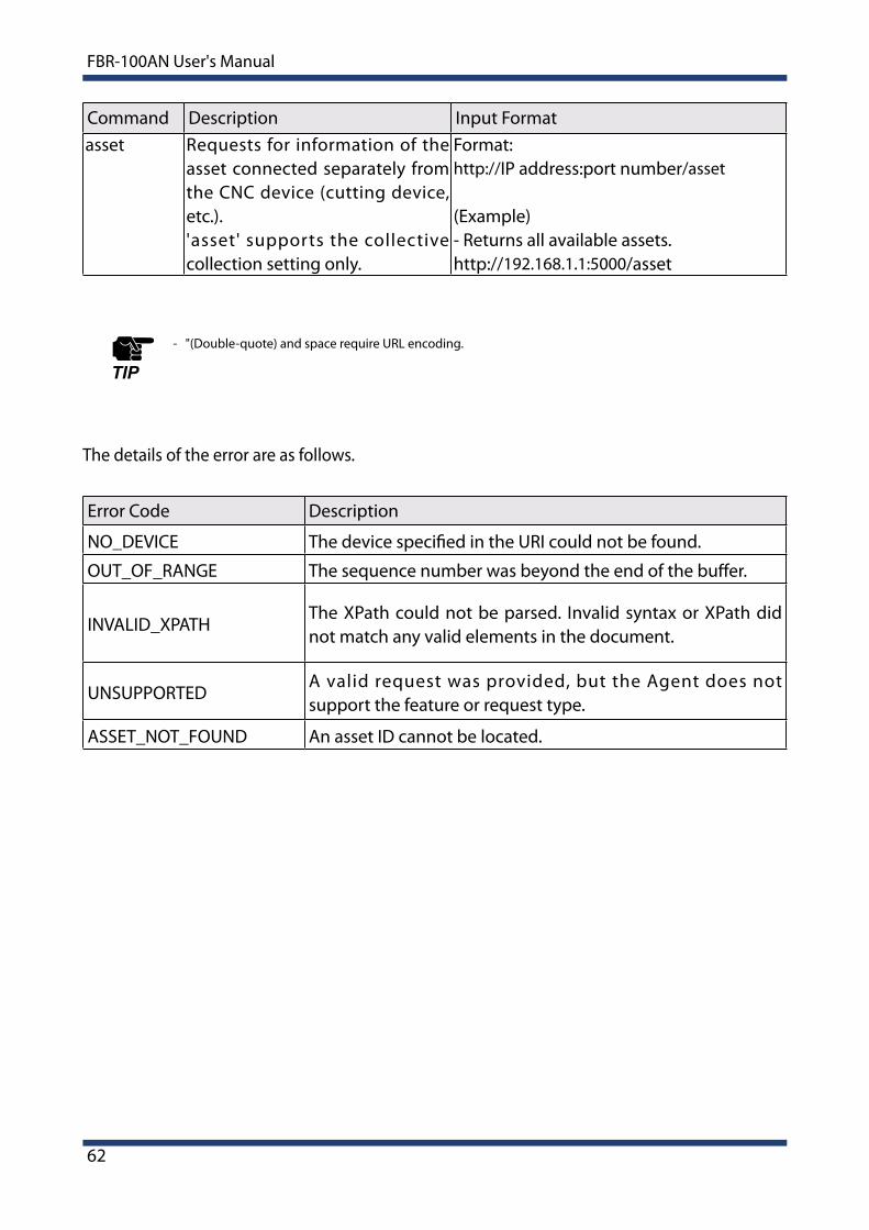
The details of the error are as follows.
Error Code Description
NO_DEVICE The device specified in the URI could not be found.
OUT_OF_RANGE The sequence number was beyond the end of the buffer.
INVALID_XPATHThe XPath could not be parsed. Invalid syntax or XPath did not match any valid elements in the document.
UNSUPPORTEDA valid request was provided, but the Agent does not support the feature or request type.
ASSET_NOT_FOUND An asset ID cannot be located.
Command Description Input Formatasset Requests for information of the
asset connected separately from the CNC device (cutting device, etc.).'asset' supports the collective collection setting only.
Format:http://IP address:port number/asset
(Example)- Returns all available assets.http://192.168.1.1:5000/asset

4. List of Functions
63
Sample of MTConnect Client Utility
MTConnect Client SDK is provided by OpenNETCF, that can be used to develop the MTConnect client utility. It is an open source project and can be downloaded from the URL below.
URL : https://opennetcf.com/category/mtconnect/

64
FBR-100AN User's Manual
4-5. FTP Setting
Open your Web browser and access the FBR-100AN's Web page.
- For details on how to access the FBR-100AN's Web page using the Web browser, refer to 3-2-2. Displaying FBR-100AN's Web Page.
Click FTP from the configuration menu.
1.
2.
Note
The following explains how to configure the FTP setting.
The FTP Configuration page is displayed.Configure each setting.
3.
- For details on each configuration item, refer to A-1. List of All Settings.
Note
4. List of Functions
65
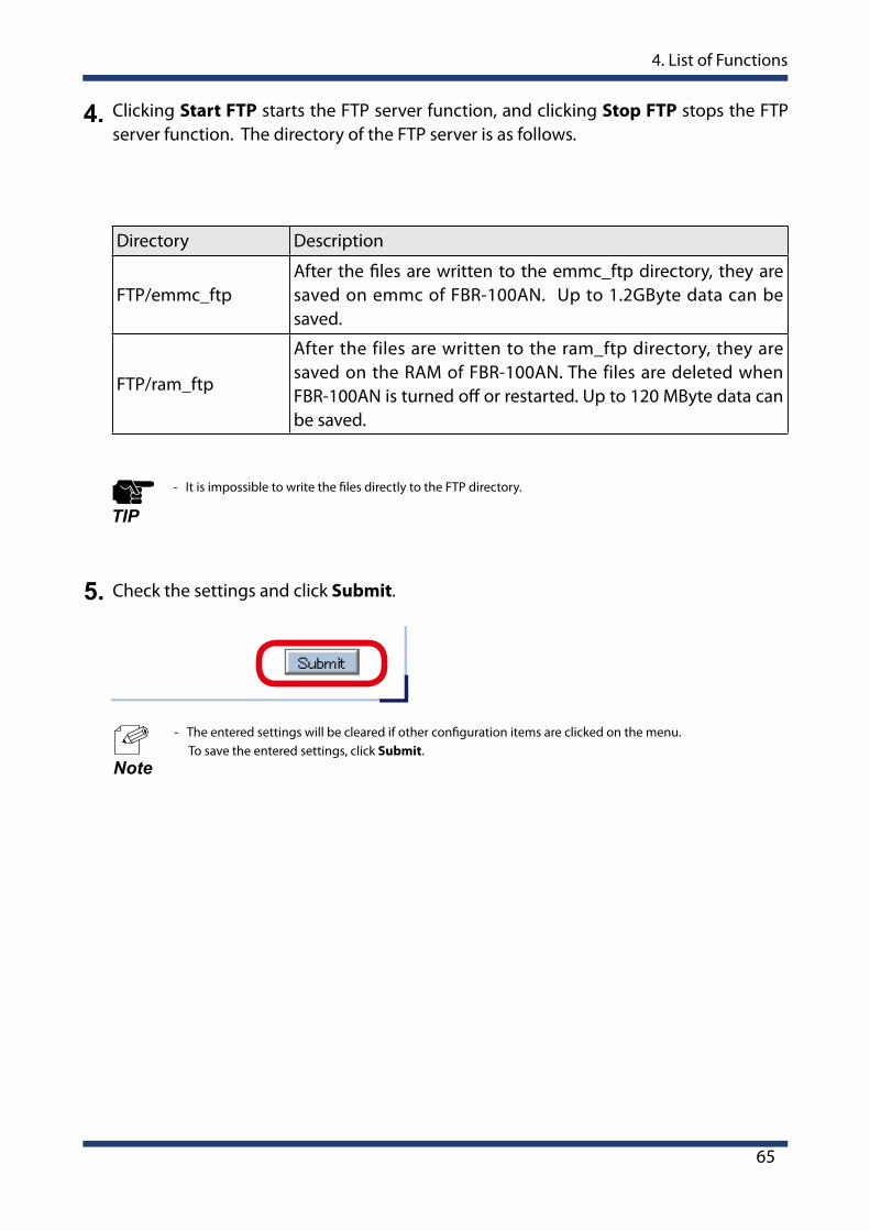
4. Clicking Start FTP starts the FTP server function, and clicking Stop FTP stops the FTP server function. The directory of the FTP server is as follows.
Directory Description
FTP/emmc_ftpAfter the files are written to the emmc_ftp directory, they are saved on emmc of FBR-100AN. Up to 1.2GByte data can be saved.
FTP/ram_ftp
After the files are written to the ram_ftp directory, they are saved on the RAM of FBR-100AN. The files are deleted when FBR-100AN is turned off or restarted. Up to 120 MByte data can be saved.
- It is impossible to write the files directly to the FTP directory.
TIP
Check the settings and click Submit.5.
- The entered settings will be cleared if other configuration items are clicked on the menu. To save the entered settings, click Submit.
Note

66
FBR-100AN User's Manual
4-6. Time Setting
Open your Web browser and access the FBR-100AN's Web page.
Click Time from the configuration menu.
1.
2.
If the time setting is configured, FBR-100AN synchronizes with the NTP server to get the time information when it is turned on. It is also possible to configure the time setting manually.
The Time Configuration page is displayed.Configure each setting.
3.
- For details on how to access the FBR-100AN's Web page using the Web browser, refer to 3-2-2. Displaying FBR-100AN's Web Page.
Note
4. List of Functions
67
- For details on each configuration item, refer to A-1. List of All Settings.
Note
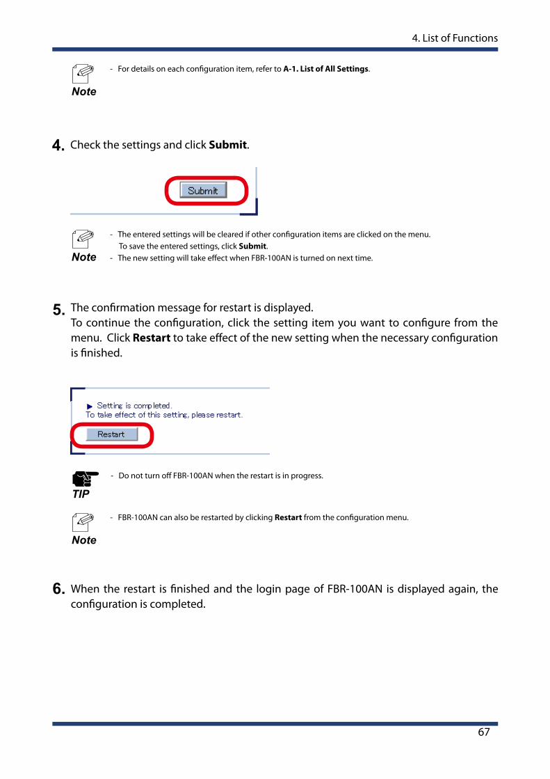
Check the settings and click Submit.4.
- The entered settings will be cleared if other configuration items are clicked on the menu. To save the entered settings, click Submit.
- The new setting will take effect when FBR-100AN is turned on next time.Note
- Do not turn off FBR-100AN when the restart is in progress.
TIP
- FBR-100AN can also be restarted by clicking Restart from the configuration menu.
Note
5. The confirmation message for restart is displayed.To continue the configuration, click the setting item you want to configure from the menu. Click Restart to take effect of the new setting when the necessary configuration is finished.
When the restart is finished and the login page of FBR-100AN is displayed again, the configuration is completed.
6.
68
FBR-100AN User's Manual
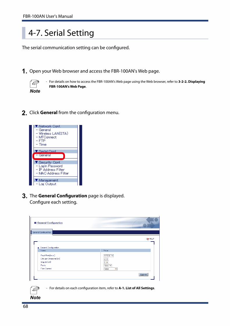
4-7. Serial SettingThe serial communication setting can be configured.
Open your Web browser and access the FBR-100AN's Web page.
- For details on how to access the FBR-100AN's Web page using the Web browser, refer to 3-2-2. Displaying FBR-100AN's Web Page.
Click General from the configuration menu.
1.
2.
Note
The General Configuration page is displayed.Configure each setting.
3.
- For details on each configuration item, refer to A-1. List of All Settings.
Note
4. List of Functions
69
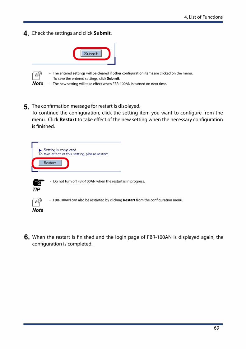
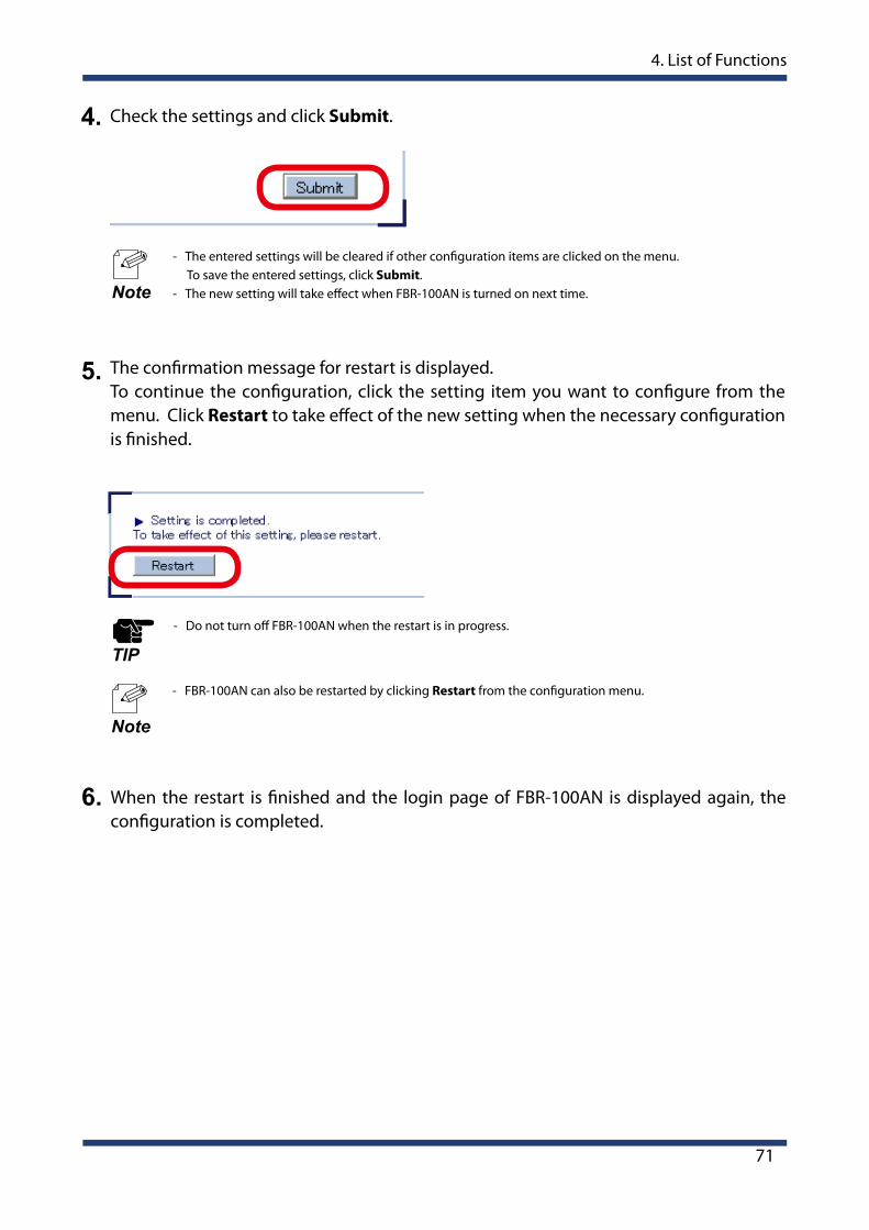
Check the settings and click Submit.4.
- The entered settings will be cleared if other configuration items are clicked on the menu. To save the entered settings, click Submit.
- The new setting will take effect when FBR-100AN is turned on next time.Note
- Do not turn off FBR-100AN when the restart is in progress.
TIP
- FBR-100AN can also be restarted by clicking Restart from the configuration menu.
Note
5. The confirmation message for restart is displayed.To continue the configuration, click the setting item you want to configure from the menu. Click Restart to take effect of the new setting when the necessary configuration is finished.
When the restart is finished and the login page of FBR-100AN is displayed again, the configuration is completed.
6.

70
FBR-100AN User's Manual
4-8. Login Password Change
Open your Web browser and access the FBR-100AN's Web page.
- For details on how to access the FBR-100AN's Web page using the Web browser, refer to 3-2-2. Displaying FBR-100AN's Web Page.
Click Login Password from the configuration menu.
The Login Password Configuration page is displayed.Configure the new password.
1.
2.
3.
Note
The following explains how to change the login password.
- For details on each configuration item, refer to A-1. List of All Settings.
Note
4. List of Functions
71
Check the settings and click Submit.4.
- The entered settings will be cleared if other configuration items are clicked on the menu. To save the entered settings, click Submit.
- The new setting will take effect when FBR-100AN is turned on next time.Note
- Do not turn off FBR-100AN when the restart is in progress.
TIP
- FBR-100AN can also be restarted by clicking Restart from the configuration menu.
Note
5. The confirmation message for restart is displayed.To continue the configuration, click the setting item you want to configure from the menu. Click Restart to take effect of the new setting when the necessary configuration is finished.
When the restart is finished and the login page of FBR-100AN is displayed again, the configuration is completed.
6.

72
FBR-100AN User's Manual
4-9. IP Address Filter
Open your Web browser and access the FBR-100AN's Web page.
- For details on how to access the FBR-100AN's Web page using the Web browser, refer to 3-2-2. Displaying FBR-100AN's Web Page.
Click IP Address Filter from the configuration menu.
The IP Address Filter Configuration page is displayed.
1.
2.
3.
Note
By registering the IP address filter, access to FBR-100AN from the specified device can be restricted. Up to 20 addresses can be registered. For each range of IP address, you can set "ALLOW" to allow access from or "DENY" to deny access from.
- If this function is used, the communication speed may slow down as the network communication is monitored. - It is possible to use this function for both wired LAN and wireless LAN.TIP
4. List of Functions
73
Adding Filter ConditionsSelect the filter mode at Filter Mode, enter the address to Starting Address and Ending Address to specify the address range, and click Add. Once the filter conditions are registered, it is displayed at Registered Conditions.
Default Filter ModeConfigure the access control setting for all IP addresses (ALLOW/DENY).When Default Filter Mode is set to ALLOW, access is allowed from all IP addresses. When it is set to DENY, access from all IP addresses is denied.
Default Filter Mode is used with Filter Mode.If Default Filter Mode is set to DENY, FBR-100AN can be accessed only from the devices whose address range is set to ALLOW at Filter Mode.
Deleting Filter ConditionsSelect the condition to remove from Registered Conditions and click Delete.
Changing Priority of Conditions to UseSelect the condition to change the priority and click [ ] button or [ ] button to make the priority of that condition higher or lower.
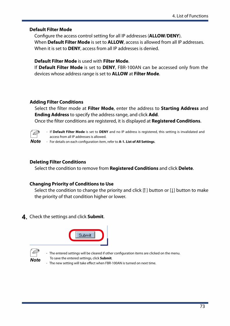
Check the settings and click Submit.4.
- The entered settings will be cleared if other configuration items are clicked on the menu. To save the entered settings, click Submit.
- The new setting will take effect when FBR-100AN is turned on next time.Note
- If Default Filter Mode is set to DENY and no IP address is registered, this setting is invalidated and access from all IP addresses is allowed.
- For details on each configuration item, refer to A-1. List of All Settings.Note

74
FBR-100AN User's Manual
When the restart is finished and the login page of FBR-100AN is displayed again, the configuration is completed.
6.
- If the IP address or network mode is changed on FBR-100AN and which does now allow communication from the PC, the login page is not displayed.
Note
- Do not turn off FBR-100AN when the restart is in progress.
TIP
5. The confirmation message for restart is displayed.To continue the configuration, click the setting item you want to configure from the menu. Click Restart to take effect of the new setting when the necessary configuration is finished.
- FBR-100AN can also be restarted by clicking Restart from the configuration menu.
Note

4. List of Functions
75
4-10. MAC Address Filter
Open your Web browser and access the FBR-100AN's Web page.
Click MAC Address Filter from the configuration menu.
The MAC Address Filter Configuration page is displayed.
1.
2.
3.
By registering the MAC Address filter, access to FBR-100AN from the specified device can be restricted. Up to 20 addresses can be registered. For each range of MAC address, you can set "ALLOW" to allow access from or "DENY" to deny access from.
- If this function is used, the communication speed may slow down as the network communication is monitored.
- It is possible to use this function for both wired LAN and wireless LAN.TIP
- For details on how to access the FBR-100AN's Web page using the Web browser, refer to 3-2-2. Displaying FBR-100AN's Web Page.
Note
- For details on each configuration item, refer to A-1. List of All Settings.
Note
76
FBR-100AN User's Manual
Check the settings and click Submit.4.
- The entered settings will be cleared if other configuration items are clicked on the menu. To save the entered settings, click Submit.
- The new setting will take effect when FBR-100AN is turned on next time.Note
When the restart is finished and the login page of FBR-100AN is displayed again, the configuration is completed.
6.
- If the IP address or network mode is changed on FBR-100AN and which does now allow communication from the PC, the login page is not displayed.
Note
- Do not turn off FBR-100AN when the restart is in progress.
TIP
5. The confirmation message for restart is displayed.To continue the configuration, click the setting item you want to configure from the menu. Click Restart to take effect of the new setting when the necessary configuration is finished.
- FBR-100AN can also be restarted by clicking Restart from the configuration menu.
Note

4. List of Functions
77
4-11. Log Output
Open your Web browser and access the FBR-100AN's Web page.
Click Log Output from the configuration menu.
1.
2.
The following explains how to output the system log from the Web page.
- For details on how to access the FBR-100AN's Web page using the Web browser, refer to 3-2-2. Displaying FBR-100AN's Web Page.
Note
The Log Output page is displayed.Click Save.
3.
Follow the instruction on the dialog to save the log.4.

78
FBR-100AN User's Manual
(blank page)

5. Maintenance Feature
79
5. Maintenance Feature
This chapter explains the maintenance feature of FBR-100AN.
- Factory Default Configuration - Restart - Firmware Update

80
FBR-100AN User's Manual
5-1. Factory Default Configuration
5-1-1. Factory Default Configuration Using Web Page
The following explains how to reset FBR-100AN to the factory default setting.
- Once the factory default configuration is executed, all settings of FBR-100AN are reset to the default ones. It is highly recommended to take a note of the current setting. Remember that not only the product settings but also files and programs of emmc will be initialized.
- Before starting the factory default configuration, make sure that no PCs are accessing FBR-100AN. - Do not turn off FBR-100AN when the initialization is in progress.
Open your Web browser and access the FBR-100AN's Web page.
- For details on how to access the FBR-100AN's Web page using the Web browser, refer to 3-2-2. Displaying FBR-100AN's Web Page.
Click Setting Initialization from the configuration menu.
1.
2.
Note
TIP
The following explains how to execute the factory default configuration using the Web page.
The Setting Initialization page is displayed.Select All for Select the target device to initialize and click Execute.
3.
5. Maintenance Feature
81
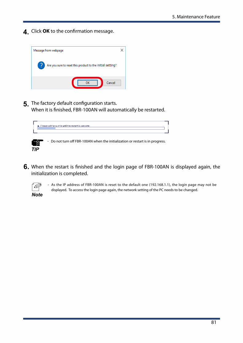
Click OK to the confirmation message.4.
5. The factory default configuration starts.When it is finished, FBR-100AN will automatically be restarted.
- Do not turn off FBR-100AN when the initialization or restart is in progress.
TIP
- As the IP address of FBR-100AN is reset to the default one (192.168.1.1), the login page may not be displayed. To access the login page again, the network setting of the PC needs to be changed.
Note
When the restart is finished and the login page of FBR-100AN is displayed again, the initialization is completed.
6.

82
FBR-100AN User's Manual
When all LEDs on top side of FBR-100AN turn orange, and then all LEDs except for PWR LED turn off, release the push switch.
When the PWR LED turns green, the factory default configuration is completed.
3.
4.
5-1-2. Factory Default Configuration Using Push Switch
Turn off FBR-100AN by unplugging the DC cable or AC adapter.1.
The following explains how to execute the factory default configuration using the push switch.
Press and hold the push switch on the front side of FBR-100AN while plugging the DC cable or AC adapter back into FBR-100AN. Keep pressing.
2.
5. Maintenance Feature
83
5-2. Restart
5-2-1. Restart by Unplugging Cables
The following explains how to restart FBR-100AN.
When all LEDs except for the PWR LED turn on, restart is completed.(The LED light pattern will differ depending on the configuration or link status of FBR-100AN.)
3.
Turn off FBR-100AN by unplugging the DC cable or AC adapter.1.
Plug the DC cable or AC adapter back into FBR-100AN. Check that the PWR LED turns green on top of FBR-100AN.
2.
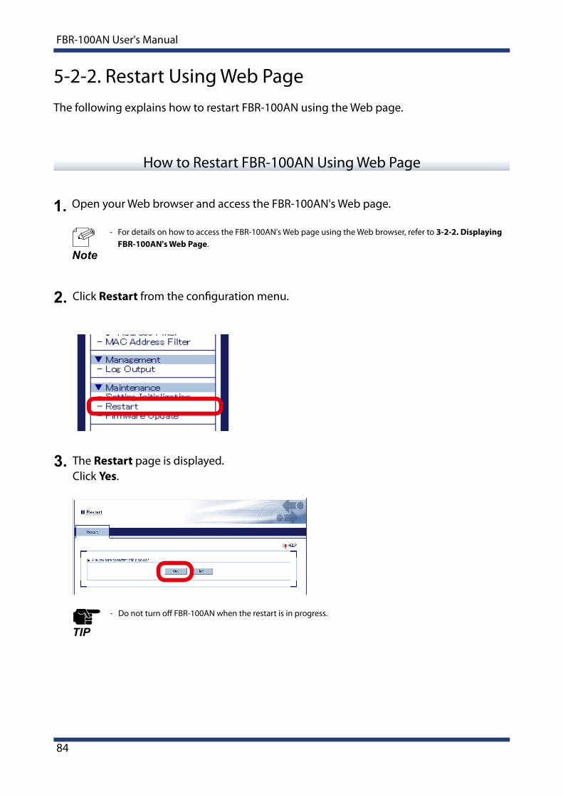
84
FBR-100AN User's Manual
- Do not turn off FBR-100AN when the restart is in progress.
TIP
5-2-2. Restart Using Web Page
Open your Web browser and access the FBR-100AN's Web page.
- For details on how to access the FBR-100AN's Web page using the Web browser, refer to 3-2-2. Displaying FBR-100AN's Web Page.
Click Restart from the configuration menu.
The Restart page is displayed. Click Yes.
1.
2.
3.
Note
How to Restart FBR-100AN Using Web Page
The following explains how to restart FBR-100AN using the Web page.

5. Maintenance Feature
85
When the restart is finished, the login page of FBR-100AN is displayed.4.
- If the IP address or network mode is changed on FBR-100AN and which does now allow communication from the PC, the login page is not displayed.
Note

86
FBR-100AN User's Manual
5-3. Firmware Update
5-3-1. Downloading Latest Firmware
Access the website below on PC.
https://www.silextechnology.com/
Download the latest firmware file from the Silex Technology's website.
The firmware of FBR-100AN can be upgraded via network.
1.
- The current firmware version can be found at the bottom left of the Web page.
Note
Go to the support page, download the firmware file and extract it on the desktop.2.
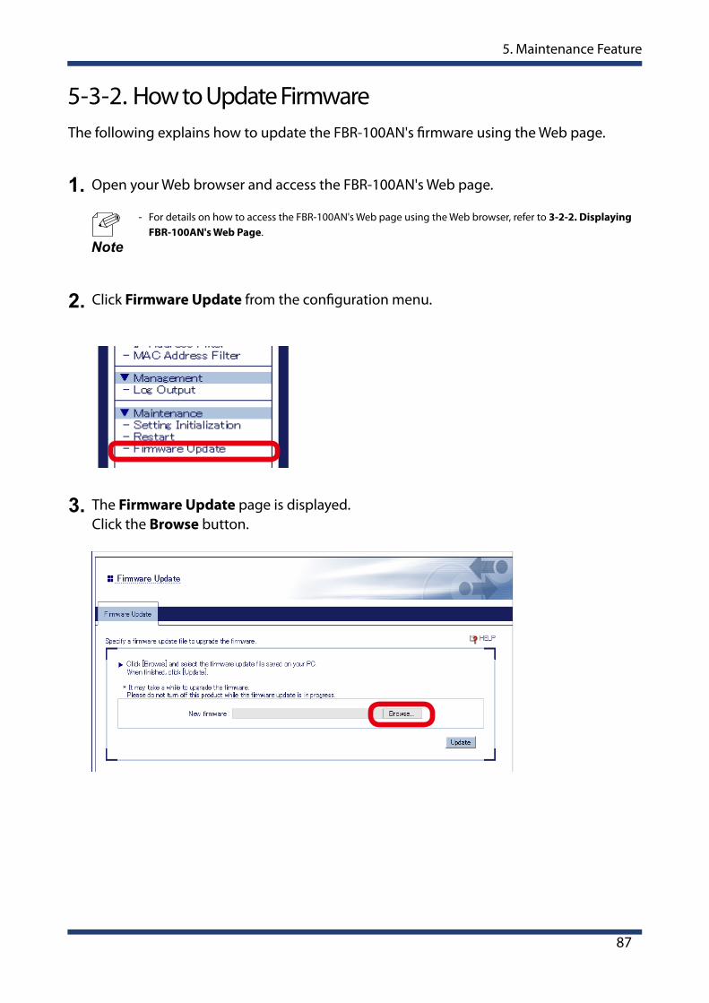
5. Maintenance Feature
87
5-3-2. How to Update Firmware
Open your Web browser and access the FBR-100AN's Web page.
- For details on how to access the FBR-100AN's Web page using the Web browser, refer to 3-2-2. Displaying FBR-100AN's Web Page.
Click Firmware Update from the configuration menu.
The Firmware Update page is displayed.Click the Browse button.
1.
2.
3.
Note
The following explains how to update the FBR-100AN's firmware using the Web page.
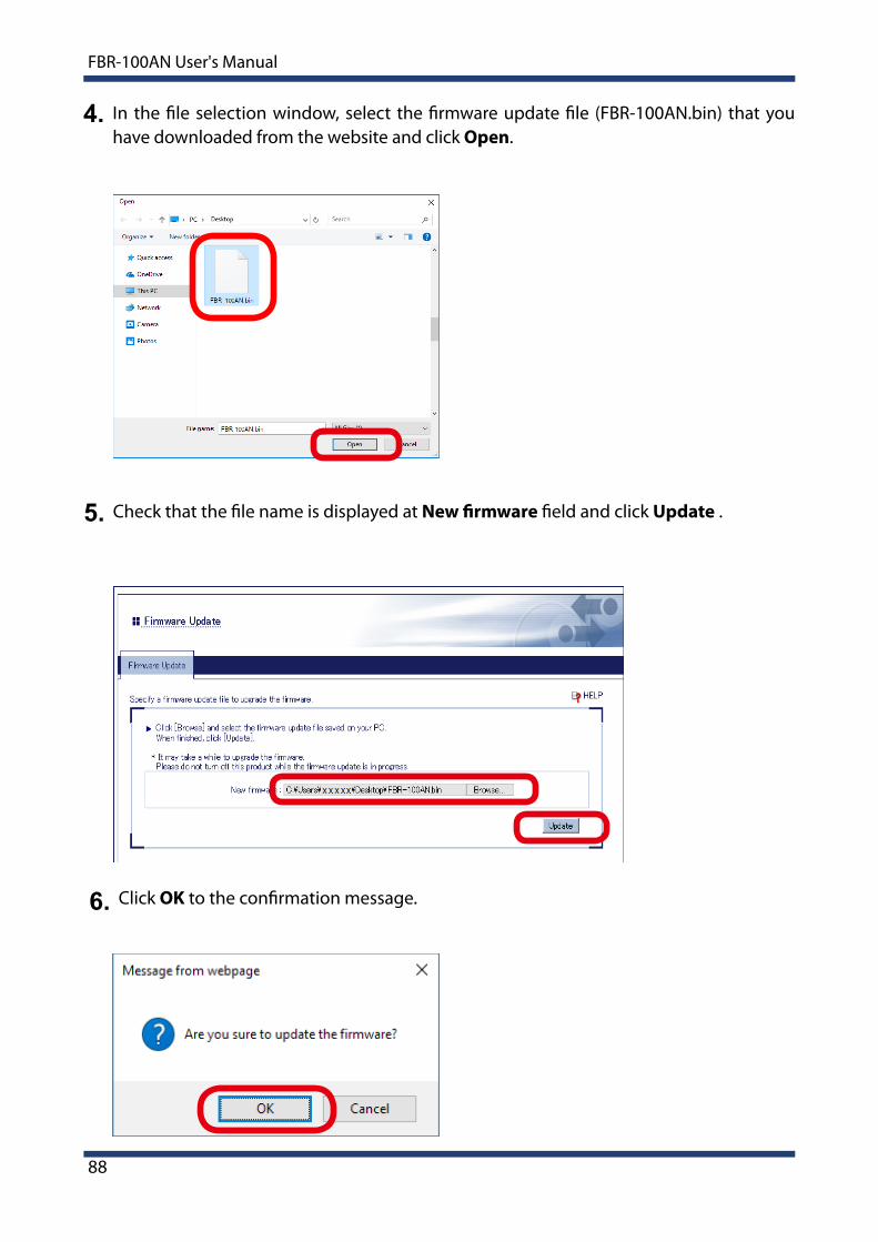
88
FBR-100AN User's Manual
Check that the file name is displayed at New firmware field and click Update .5.
In the file selection window, select the firmware update file (FBR-100AN.bin) that you have downloaded from the website and click Open.
4.
Click OK to the confirmation message.6.

5. Maintenance Feature
89
The firmware update starts.When the update is finished, FBR-100AN will automatically be restarted.
When the restart is finished and the login page is displayed, firmware update is completed. Check that the new firmware version is displayed at the bottom left of Web page.
7.
8.
- Do not turn off FBR-100AN or close your Web browser while the firmware update is in process. - Do not turn off FBR-100AN when the restart is in progress.TIP

90
FBR-100AN User's Manual
(blank page)

A. Appendix
91
A. Appendix
This chapter explains each configuration item available on FBR-100AN.
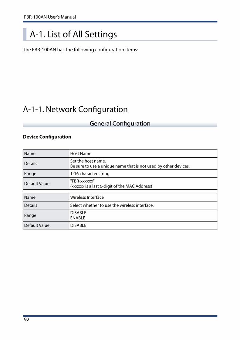
92
FBR-100AN User's Manual
A-1. List of All Settings
Name Host Name
Details Set the host name. Be sure to use a unique name that is not used by other devices.
Range 1-16 character string
Default Value "FBR-xxxxxx"(xxxxxx is a last 6-digit of the MAC Address)
Name Wireless Interface
Details Select whether to use the wireless interface.
Range DISABLEENABLE
Default Value DISABLE
Device Configuration
A-1-1. Network Configuration
General Configuration
The FBR-100AN has the following configuration items:
A. Appendix
93
Name Network operation mode
Details
Set the operating mode of FBR-100AN.
- EdgeIP address/subnet mask are assigned for each interface.
- Bridge Wired interfaces are grouped into one network, and IP address/subnet mask are assigned to it. Wireless interface will have another IP address/subnet mask.
Range EdgeBridge
Default Value Edge
Name Default Gateway
Details
Set the default gateway address.If "0.0.0.0" is set, this setting is disabled.
When the configured address is not found on the network segment of each interface, the value obtained from DHCP is applied.
Range 0.0.0.0 - 255.255.255.255
Default Value 0.0.0.0
Name Link Speed Port 1 / 2
Details Set a link speed for wired LAN port.
Range
AUTO10 BASE-T-Half10 BASE-T-Full100 BASE-TX-Half100 BASE-TX-Full1000 BASE-T-Full
Default Value AUTO

94
FBR-100AN User's Manual
Name Resolution Protocol Configuration
Name DNS Suffix
Details Set the DNS suffix.
Range 0-255 character string (letters, numbers, period, hyphen)
Default Value (None)
Name DNS Server (Primary)
DetailsSet a primary DNS server address.When DHCP client is enabled, the DNS server address obtained from DHCP server will be applied.
Range 0.0.0.0 - 255.255.255.255
Default Value 0.0.0.0
Name DNS Server (Secondary)
DetailsSet a secondary DNS server address.When DHCP client is enabled, the DNS server address obtained from DHCP server will be applied.
Range 0.0.0.0 - 255.255.255.255
Default Value 0.0.0.0

A. Appendix
95
LAN Port1 / LAN Port2 / WLAN Port / Bridge Port
Name DHCP Client
Details Select whether to use the DHCP client function.
Range DISABLEENABLE
Default Value DISABLE (LAN Port1, LAN Port2, Bridge Port)ENABLE (WLAN Port)
Name IP Address
Details Set an IP address.
Range 0.0.0.0 - 255.255.255.255
Default Value
192.168.1.1 (LAN Port1)192.168.2.1 (LAN Port2)0.0.0.0 (WLAN Port)192.168.3.1 (Bridge Port)
Name Subnet Mask
Details Set a subnet mask.
Range 0.0.0.0 - 255.255.255.255
Default Value 255.255.255.0

96
FBR-100AN User's Manual
Wireless LAN (STA) - Easy Configuration
Name SSID
Details Access Points are searched and shown on the SSID list.Select the SSID of the Access Point you want to connect.
Range -
Default Value -
Name Network Key
DetailsEnter the network key to connect the wireless devices.The authentication method will differ depending on the selected Access Point.
Range
When Shared is used:- 5-digit or 13-digit character string- 10-digit or 26-digit hexadecimal number
When WPA or WPA2 is used:- A string with 8-64 ASCII characters including symbols
Default Value (None)

A. Appendix
97
Wireless LAN Basic Configuration
Name SSID
Details
Set an SSID for wireless LAN of FBR-100AN.SSID is an ID to distinguish one network group from the others in wireless LAN. The devices must share the same SSID to communicate with each other in wireless LAN.
Range A string with 1-32 ASCII characters including symbols
Default Value "SSID"
Name Network Authentication
Details Select the network authentication mode.
Range
OpenSharedWPA2-PSKWPA/WPA2-PSKWPA2-EAPWPA/WPA2-EAP
Default Value Open
Name Encryption Mode
Details Select the encryption mode.
Range AUTO / AES
Default Value When WPA2-PSK or WPA2-EAP is used : AESWhen WPA/WPA2-PSK or WPA/WPA2-EAP is used : AUTO
Wireless LAN (STA) - Detailed Configuration
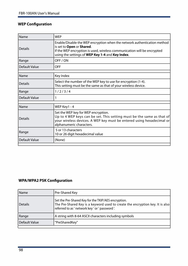
98
FBR-100AN User's Manual
WEP Configuration
Name WEP
Details
Enable/Disable the WEP encryption when the network authentication method is set to Open or Shared. If the WEP encryption is used, wireless communication will be encrypted using the settings of WEP Key 1-4 and Key Index.
Range OFF / ON
Default Value OFF
Name Key Index
Details Select the number of the WEP key to use for encryption (1-4).This setting must be the same as that of your wireless device.
Range 1 / 2 / 3 / 4
Default Value 1
Name WEP Key1 - 4
Details
Set the WEP key for WEP encryption.Up to 4 WEP keys can be set. This setting must be the same as that of your wireless devices. A WEP key must be entered using hexadecimal or alphanumeric characters.
Range 5 or 13 characters10 or 26 digit hexadecimal value
Default Value (None)
WPA/WPA2 PSK Configuration
Name Pre-Shared Key
DetailsSet the Pre-Shared Key for the TKIP/AES encryption.The Pre-Shared Key is a keyword used to create the encryption key. It is also referred to as ' network key ' or ' password '.
Range A string with 8-64 ASCII characters including symbols
Default Value "PreSharedKey"

A. Appendix
99
WPA/WPA2 EAP Configuration
Name Authentication Method
Details Set the authentication method to use for IEEE 802.1X authentication.
Range
EAP-TLSEAP-TTLSPEAPEAP-FASTLEAP
Default Value EAP-TLS
Name EAP User Name
Details Set an EAP user name for the IEEE 802.1X authentication.This name is used by the server to identify a client.
Range A string with 0-64 ASCII characters including symbols
Default Value (None)
Name EAP Password
DetailsSet an EAP password for the IEEE 802.1X authentication.It is used to check the reliability of the client when the authentication method other than EAP-TLS is set.
Range A string with 0-32 ASCII characters including symbols
Default Value (None)
Name Inner Authentication Method
Details
Set a method for inner authentication (PAP/CHAP/MSCHAP/MSCHAPv2) to run within TLS tunneling of the IEEE 802.1X authentication. This setting is displayed when the authentication method is set to EAP-TTLS or PEAP, and is fixed to MSCHAPv2 when PEAP is used.
Range
PAPCHAPMSCHAPMSCHAPv2
Default Value PAP
Name Client Certificate Password
Details
Set a client certificate password to use for client authentication of IEEE 802.1X authentication. This setting is necessary when a password is set to the client certificate. This is used when EAP-TLS is used as authentication method.
Range A string with 0-32 ASCII characters including symbols
Default Value (None)

100
FBR-100AN User's Manual
Name Client Certification
DetailsSelect a client certificate to use for client authentication of IEEE 802.1X authentication. This is used when EAP-TLS is used as authentication method.
Range Upload the client certificate.
Default Value -
Name Server Authentication
Details
Set whether to verify that the server certificate is issued from a trusted root certification authority when EAP-TLS, EAP-TTLS or PEAP authentication mode is used. When this setting is enabled, CA certificate is required since verification of the server certificate runs.
Range OFF / ON
Default Value OFF
Name CA Certification
Details Select a CA certificate to use for server authentication. This setting is displayed when the server authentication is enabled.
Range Upload the CA certificate.
Default Value -
Name Auto PAC Provisioning
DetailsEnable/Disable automatic distribution of PAC file. When this setting is disabled, the PAC file issued from the server is required. This setting is displayed when the authentication method is set to EAP-FAST.
Range OFF / ON
Default Value OFF
Name PAC File Distribution
DetailsRegister the PAC file issued from the server to use for manual distribution of PAC (Protected Access Credential) when using EAP-FAST authentication.This setting is displayed when the authentication method is set to EAP-FAST.
Range Upload the PAC file.
Default Value -

A. Appendix
101
Certificate Registration StatusWhen WPA2-EAP or WPA/WPA2-EAP is selected for network authentication, the registration status of following certificates is displayed.
Name Client Certification
Details This is a certif icate fi le to authenticate FBR-100AN for IEEE802.1X authentication.
Range
The certificate registration status is displayed.
Not RegisteredRegistered
Default Value Not Registered
Name CA Certification
Details This is a CA certificate file to authenticate a certificate sent from the RADIUS server when IEEE802.1X authentication is used.
Range
The certificate registration status is displayed.
Not RegisteredRegistered
Default Value Not Registered
Name PAC File Distribution
Details Register the PAC file issued from the server to use for manual distribution of PAC (Protected Access Credential) when using EAP-FAST authentication.
Range
The certificate registration status is displayed.
Not RegisteredRegistered
Default Value Not Registered

102
FBR-100AN User's Manual
Common Configuration
Name MTConnect Mode
Details
Set the MTConnect operating mode.
- adapter & agentWhen accessed from the client, FBR-100AN replies in XML format data.
- adapterWhen accessed from the client, FBR-100AN replies in SHDR format data (format with vertical separation lines '|').
Range adapter & agentadapter
Default Value adapter & agent
Name Data Acquisition Mode
Details
Set the MTConnect data collection mode.
- Individual Based on the imported point-file, FBR-100AN collects the data of each point individually.- Collective(Network) The data is collected at once using the configured PMC information. The collected data is analyzed based on the imported device information.- Collective(DPRNT) The DPRNT specification data is collected at once after it is sent from serial (RS-232C).
RangeIndividualCollective(Network)Collective(DPRNT)
Default Value Individual
MTConnect Configuration - Common Configuration
A. Appendix
103
"Import the Individual's point file"
"Export the Collective(Network)'s devices info"
Import the file created by the point file generation tool.
"Export the Individual's point info"
"Import the Collective(Network)'s devices info"
Import the file created by the device information generation tool.
Export the device information file configured to FBR-100AN.
- To create a file to import, use the point file generation utility or device information generation utility.
TIP
Export the point file configured to FBR-100AN.

104
FBR-100AN User's Manual
MTConnect Configuration - Individual Configuration
Individual Configuration1 - 3
Name MTConnect Port(HTTP)
Details Set the port number to be used for MTConnect (HTTP) communication.
Range 0 - 32767
Default Value 5000 - 5002 (when MTConnect Mode is adapter & agent)7878 - 7880 (when MTConnect Mode is agent)
Name MTConnect Port(HTTPS)
Details Set the port number to be used for MTConnect (HTTPS) communication.
Range 0 - 32767
Default Value 5443 - 5445 (when MTConnect mode is adapter & agent)7443 - 7445 (when MTConnect mode is agent)
Name CNC IP Address
Details Set the IP address of CNC to be connected.
Range 0.0.0.0 - 255.255.255.255
Default Value 0.0.0.0
Name CNC Port
Details Set the port number of CNC to be connected.
Range 0 - 65535
Default Value 8193
Name CNC Connect Timeout[s]
Details Set the CNC communication timeout (seconds).
Range 0 - 100
Default Value 10
Name CNC Connect Interval[ms]
Details Set the CNC communication interval (milliseconds).It is recommended to set a value of 100ms or more.
Range 0 - 1000
Default Value 0
Up to 3 CNC devices can be specified for Individual Configuration.When multiple CNC devices are connected, the number of collectable data is limited. For details, refer to the description on the point file generation utility.

A. Appendix
105
MTConnect Configuration - Collective Configuration
Collective Configuration
Name MTConnect Port(HTTP)
Details
Set the port number to be used for MTConnect (HTTP) communication.
This setting is used even when Collective (DPRNT) is selected for the data acquisition mode.
Range 0 - 32767
Default Value 5000 (when MTConnect mode is adapter & agent)7878 (when MTConnect mode is agent)
Name MTConnect Port(HTTPS)
Details
Set the port number to be used for MTConnect (HTTPS) communication.
This setting is used even when Collective (DPRNT) is selected for the data acquisition mode.
Range 0 - 32767
Default Value 5443 (when MTConnect mode is adapter & agent)7443 (MTConnect mode is agent)
Name Collection Interval[ms]
Details
Set the data collection interval (milliseconds).
This setting is used even when Collective (DPRNT) is selected for the data acquisition mode.
Range 30 - 1800000
Default Value 100
Name CNC IP Address
Details Set the IP address of CNC to be connected.
Range 0.0.0.0 - 255.255.255.255
Default Value 0.0.0.0
Name CNC Port
Details Set the port number of CNC to be connected.
Range 0 - 65535
Default Value 8193
Only one CNC device can be specified for Collective Configuration.

106
FBR-100AN User's Manual
Name CNC Connect Timeout[s]
Details Set the CNC communication timeout (seconds).
Range 0 - 100
Default Value 10
Name CNC Connect Interval[ms]
Details Set the CNC communication interval (milliseconds).It is recommended to set a value of 100ms or more.
Range 0 - 1000
Default Value 0
Name PMC Address Type
Details Set the type of PMC address.This must be the same address type as PMC.
Range 0 - 32767
Default Value 5
Name PMC Data Type
Details Set the type of PMC data.This must be the same data type as PMC.
Range 0Default Value 0 - 32767
Name PMC Start Number
Details Set the PMC address number to start reading from.
Range 0 - 65536
Default Value 12000
Name PMC End Number
Details Set the PMC address number to finish reading at.
Range 0 - 65536
Default Value 12999
Name Collection counter gap
Details Set how much gap is acceptable when data is collected.
Range 0 - 100
Default Value 1
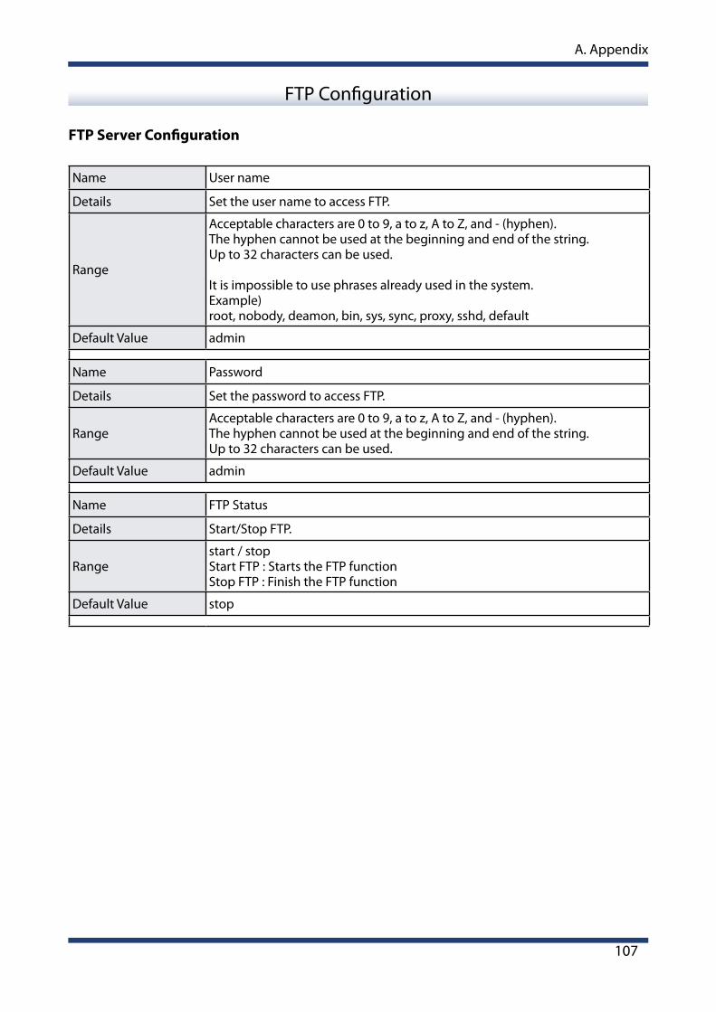
A. Appendix
107
FTP Server Configuration
Name User name
Details Set the user name to access FTP.
Range
Acceptable characters are 0 to 9, a to z, A to Z, and - (hyphen). The hyphen cannot be used at the beginning and end of the string. Up to 32 characters can be used.
It is impossible to use phrases already used in the system.Example)root, nobody, deamon, bin, sys, sync, proxy, sshd, default
Default Value admin
Name Password
Details Set the password to access FTP.
RangeAcceptable characters are 0 to 9, a to z, A to Z, and - (hyphen). The hyphen cannot be used at the beginning and end of the string. Up to 32 characters can be used.
Default Value admin
Name FTP Status
Details Start/Stop FTP.
Rangestart / stopStart FTP : Starts the FTP functionStop FTP : Finish the FTP function
Default Value stop
FTP Configuration
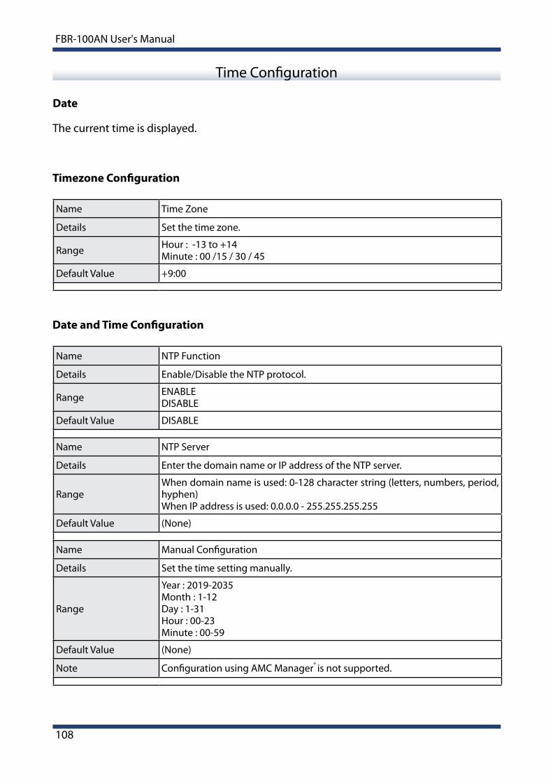
108
FBR-100AN User's Manual
Date
Time Configuration
Timezone Configuration
Name Time Zone
Details Set the time zone.
Range Hour : -13 to +14Minute : 00 /15 / 30 / 45
Default Value +9:00
The current time is displayed.
Date and Time Configuration
Name NTP Function
Details Enable/Disable the NTP protocol.
Range ENABLEDISABLE
Default Value DISABLE
Name NTP Server
Details Enter the domain name or IP address of the NTP server.
RangeWhen domain name is used: 0-128 character string (letters, numbers, period, hyphen)When IP address is used: 0.0.0.0 - 255.255.255.255
Default Value (None)
Name Manual Configuration
Details Set the time setting manually.
Range
Year : 2019-2035Month : 1-12Day : 1-31Hour : 00-23Minute : 00-59
Default Value (None)
Note Configuration using AMC Manager® is not supported.

A. Appendix
109
General Configuration
General Configuration
A-1-2. Serial Configuration
Name Baud Rate[baud]
Details Set the data transmission/reception speed for the port.
Range
3006001200180024004800960019200288003840057600115200
Default Value 115200
Name Bits per Character[bit]
Details Set the number of bits per character.
Range 7 / 8
Default Value 8
Name Stop bit[bit]
Details Set the number of stop bits after each character.
Range 1 / 2
Default Value 1
Name Parity
Details Select the parity scheme for each character.
RangeNoneOddEven
Default Value None

110
FBR-100AN User's Manual
Name Flow Control
Details Select the flow control method.
RangeNoneXON/XOFFRTS/CTS
Default Value None
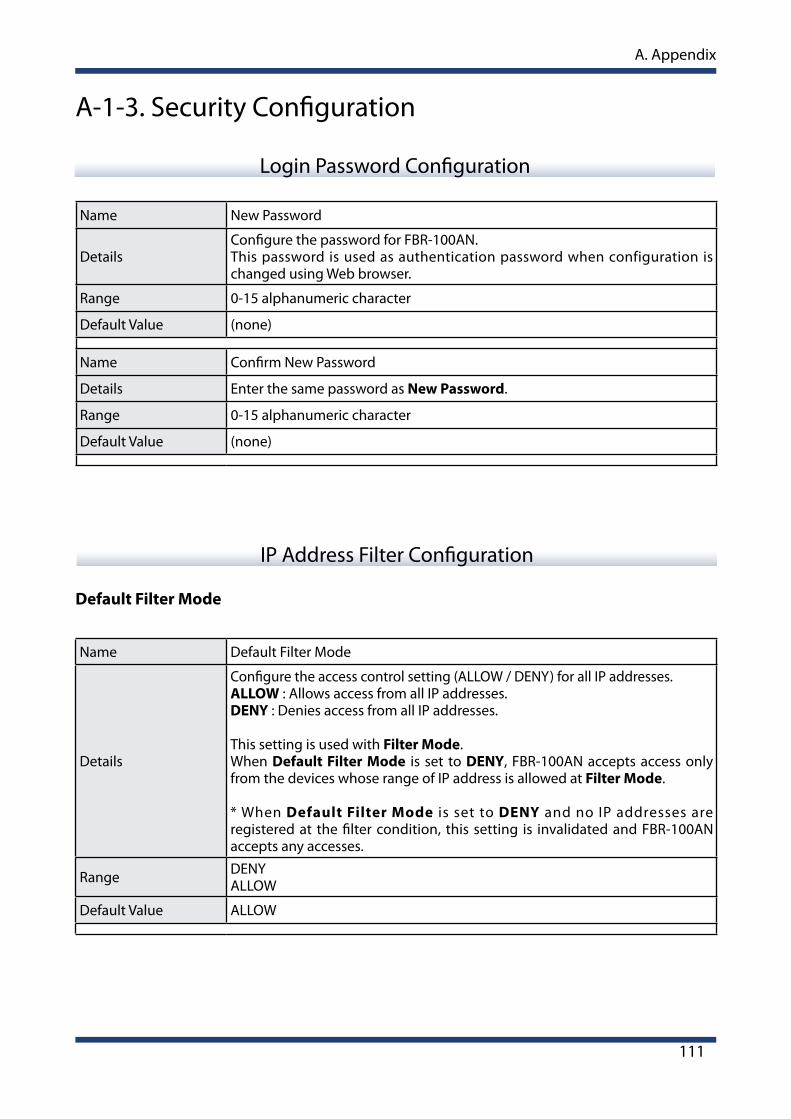
A. Appendix
111
Login Password Configuration
A-1-3. Security Configuration
IP Address Filter Configuration
Default Filter Mode
Name Default Filter Mode
Details
Configure the access control setting (ALLOW / DENY) for all IP addresses.ALLOW : Allows access from all IP addresses.DENY : Denies access from all IP addresses.
This setting is used with Filter Mode.When Default Filter Mode is set to DENY, FBR-100AN accepts access only from the devices whose range of IP address is allowed at Filter Mode.
* When Default Filter Mode is set to DENY and no IP addresses are registered at the filter condition, this setting is invalidated and FBR-100AN accepts any accesses.
Range DENYALLOW
Default Value ALLOW
Name New Password
DetailsConfigure the password for FBR-100AN.This password is used as authentication password when configuration is changed using Web browser.
Range 0-15 alphanumeric character
Default Value (none)
Name Confirm New Password
Details Enter the same password as New Password.
Range 0-15 alphanumeric character
Default Value (none)

112
FBR-100AN User's Manual
New Conditions
Name Filter Mode
Details
Configure the filter mode (ALLOW / DENY) for the specified address range.
ALLOW : Allows access from the registered IP address range.DENY : Denies access from the registered IP address range.
Range DENYALLOW
Default Value DENY
Name Starting Address
Details Set the start address for address filter.Up to 20 addresses can be registered.
Range 0.0.0.0 - 255.255.255.255
Default Value 0.0.0.0
Name Ending Address
Details Set the end address for address filter.Up to 20 addresses can be registered.
Range 0.0.0.0 - 255.255.255.255
Default Value 0.0.0.0
Registered Condition Management
Name Registered Conditions
Details Shows the registered address filter conditions.
Range (Filter Mode) : (Start Address) - (End Address)
Default Value None (blank)
Name Priority Configuration
Details Set the priority of the registered conditions.
Range : Set Priority Higher / : Set Priority Lower
Default Value -

A. Appendix
113
MAC Address Filter Configuration
Name Filter Type
Details
Set a security type for MAC Address filter (DENY/ALLOW).
DENY : Denies access from the devices registered to MAC Address filter list.ALLOW : Allows access only from the devices registered to MAC Address filter.
Range ALLOWDENY
Default Value DENY
Name MAC Address
Details
Set the MAC Address filter.By registering the MAC Address filter, access to FBR-100AN can be controlled. (Up to 20 addresses can be registered.)
* If the filter type is set to ALLOW and MAC Address (to allow access from) is not registered, access to FBR-100AN is invalidated.
Range 00:00:00:00:00:01 - FF:FF:FF:FF:FE
Default Value 00:00:00:00:00:00
MAC Address Filter Configuration

114
FBR-100AN User's Manual
(blank page)