Protection and substation control
38
chapter 8 Protection and Substation Control
-
Upload
mahmoud-ibrahim-shaker -
Category
Education
-
view
54 -
download
7
Transcript of Protection and substation control
chapter 8
Protection and Substation Control
TIP_Kap_08_Engl 11.08.2005 19:35 Uhr Seite C
General overview
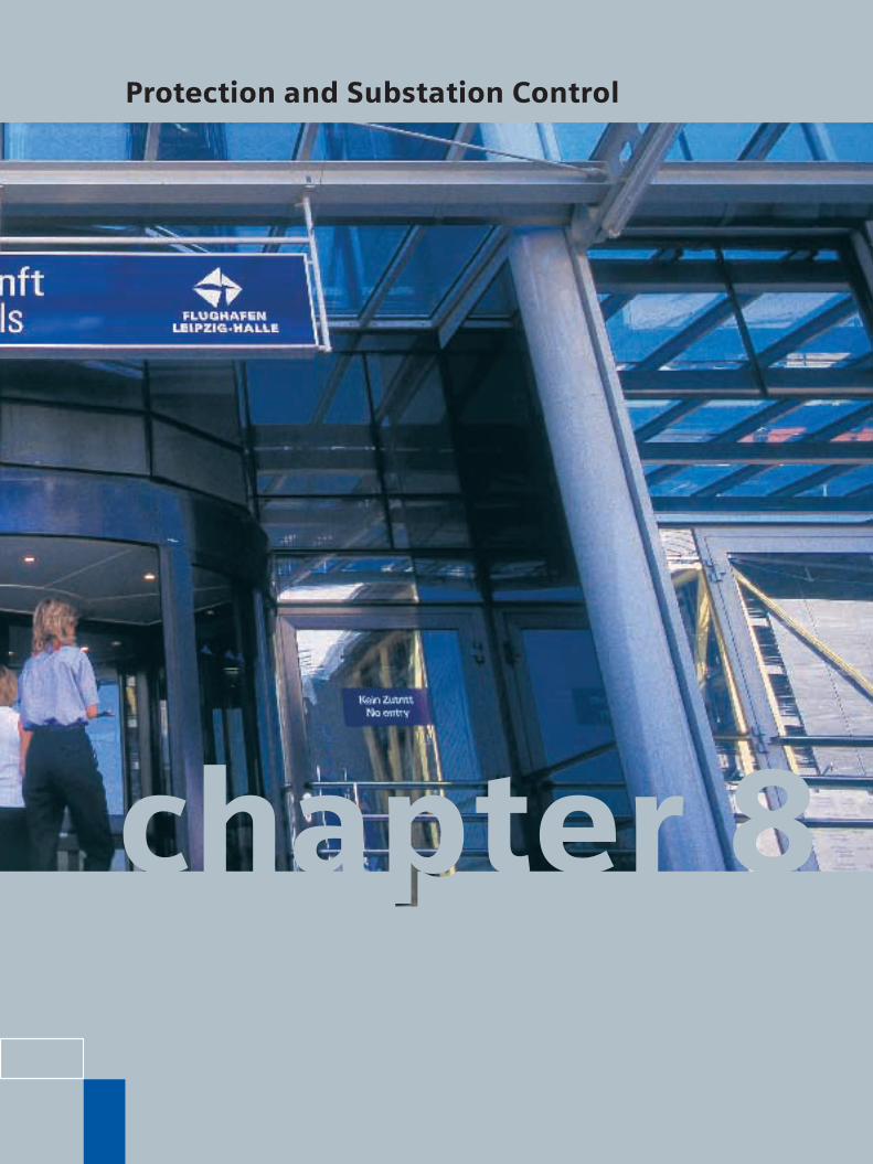
Three trends have emerged in thesphere of power automation: distrib-uted intelligent electronic devices(IED’s), open communication and PC-assisted HMI’s. Numerical relaysand computerized substation controlare now state-of-the-art.
The multitude of conventional, indi-vidual devices prevalent in the pastas well as comprehensive parallelwiring are being replaced by a smallnumber of multifunctional deviceswith serial connections.
One design for all applications
In this respect, Siemens offers a uniform, universal technology for theentire functional scope of power au-tomation equipment, both in the con-struction and connection of the de-vices and in their operation and com-munication. This results in uniformityof design, coordinated interfaces andthe same operating concept beingestablished throughout, whether inpower system and generator protec-tion, in measurement and recordingsystems, in substation control andprotection or in telecontrol.
All devices are highly compact andimmune to interference, and aretherefore also suitable for direct in-stallation in switchgear cells. Further-more, all devices and systems areself-monitoring, which means thatpreviously costly maintenance can be reduced considerably.
8 Protection and Substation Control
Totally Integrated Power by Siemens8/2
Fig. 8/1 The digital SICAM substation control system implements all of the control,measurement and automation functions of a substation. Protective relaysare connected serially.
Power systemcontrol center
CorporateNetwork TCP/IP
HMIStation unit“Full server“
IEC 60870-5-101 IEC 60870-5-104
Station bus
Serial Hub
Ethernet TCP/IP
IEC 61850
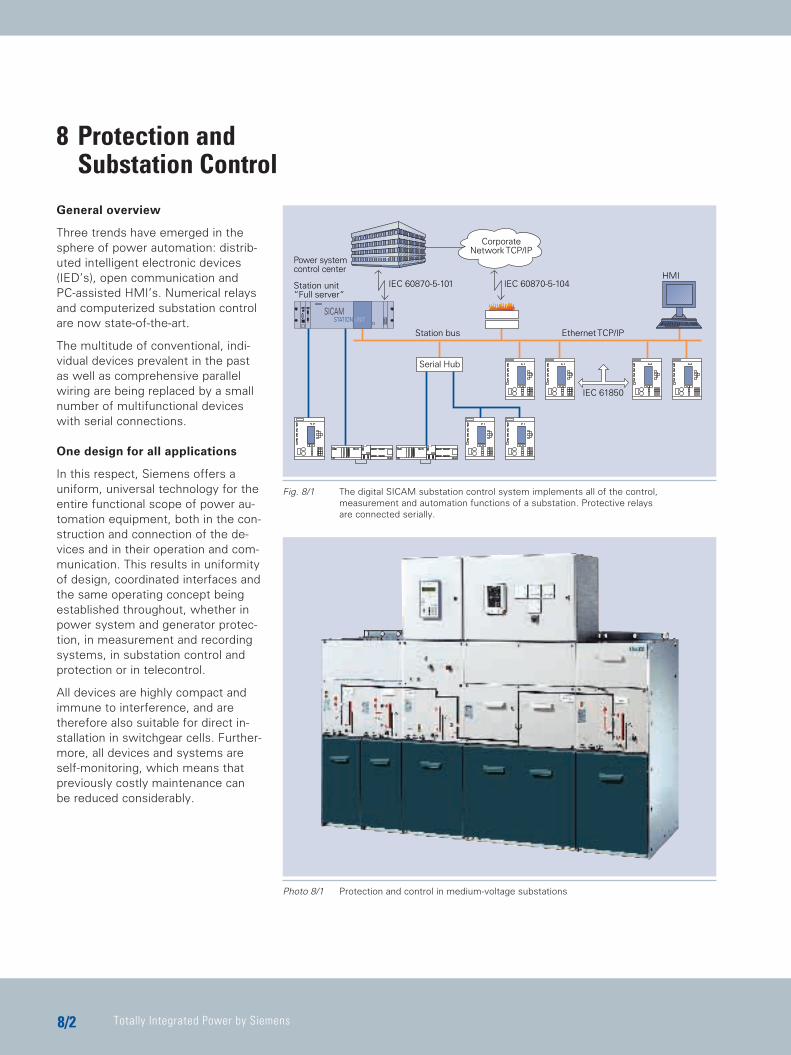
Photo 8/1 Protection and control in medium-voltage substations
TIP_Kap_08_Engl 11.08.2005 19:36 Uhr Seite 2
Protection and Substation Control
88/3
Entire technology from one partner
The Siemens Power Transmissionand Distribution Group supplies devices and systems for:
C Power plant protectionC Substation control / power
system control C Remote control (RTU’s)C Current measurement and
recordingC Measurement and monitoring
of power quality
This covers all of the measurement,control, automation and protectionfunctions for substations.Furthermore, our activities cover:C ConsultingC PlanningC DesignC Commissioning and Service
This uniform technology ”from a singlesource“ saves the customer time andmoney in the planning, installationand operation of his substations.
SIPROTEC protective relays
Siemens offers a complete spectrumof multifunctional, numerical relaysfor all applications in the field ofpower system and machine protection.
Uniform design and a metal-enclosedconstruction with conventional con-nection terminals which is free fromelectromagnetic interference in ac-cordance with public utility require-ments assure simple system designand usage just as with conventionalrelays.
Numerical measurement techniquesensure precise operation and requireless maintenance thanks to their continuous self-monitoring capability.
The integration of additional protec-tive and other functions, such as real-time operational measurements,event and fault recording, all in oneunit economizes on space, configura-tion and wiring costs.
Setting and programming of the de-vices can be performed through theintegral, plain-text, menu-guided op-erator display or by using the com-fortable DIGSI 4® PC software.
For communication at the telecontrolor substation control level, devices ofthe SIPROTEC 4 group can be equippedwith exchangeable communicationsmodules. Besides an optimal integra-tion into the SICAM PAS substationcontrol system in compliance withIEC 61850, the following protocolsare supported: PROFIBUS FMS, IEC60870-5-103, PROFIBUS DP, DNPV3.00 and Modbus.
Thus, the on-line measurements andfault data recorded in the protectiverelays can be used for local and re-mote control or can be transmittedvia telephone modem connections tothe workplace of the circuit engineer.
Siemens supplies individual devicesas well as complete protection sys-tems in factory-assembled cabinets.For complex applications, type anddesign test facilities are available to-gether with extensive network mod-els using the most modern simula-tion and evaluation techniques.
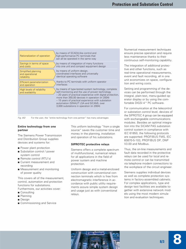
by means of SCADA-like control andhigh-performance PC terminals thatcan all be operated in the same way
Rationalization of operation
by means of integration of many functionsinto one unit and compact equipment design
Savings in terms of spaceand costs
by means of uniform design,coordinated interfaces and universallyidentical operating software
Simplified planningand operationalreliability
Efficient parameterizationand operation
thanks to PC terminals with uniform operatorinterfaces
High levels of reliabilityand availability
by means of type-tested system technology, completeself-monitoring and the use of proven technology– 20 years of practical experience with digital protection,more than 350,00 devices in operation (in 2004)– 15 years of practical experience with substationautomation (SINAUT LSA and SICAM), over3,000 substations in operation (in 2004)
Fig. 8/2 For the user, the “entire technology from one partner” has many advantages
TIP_Kap_08_Engl 11.08.2005 19:36 Uhr Seite 3
Totally Integrated Power by Siemens8/4
Substation control
The digital substation control sys-tems of the SICAM family provide allcontrol, measurement and automa-tion functions (e.g. transformer tapchanging) required by a switchingstation. They operate with distributedintelligence. Communication betweendevices in branch circuits and thecentral unit is made via fiber-opticconnections which are immune to interference.
Devices are extremely compact andcan be built directly into medium- and high-voltage switchgear.
SICAM PAS engineering tools arebased on Microsoft operating sys-tems, and thanks to their Windowslook & feel they are easy to use. ThePC-based SICAM PAS UI – Configura-tion software is used for system configuration and parameterization.SICAM PAS UI – Operation andSICAM Value Viewer support theuser during configuration and com-missioning and provide diagnosticfunctions for the system in operation.
The operator interface is menu-guided, with SCADA-comparablefunctions, that is, with a level of con-venience which was previously onlyavailable in a power system controlcenter. Optional telecontrol functionscan be added to allow coupling of thesystem to one or more power sys-tem control centers.
In contrast to conventional substationcontrol systems, digital technologysaves enormously on space andwiring. SICAM systems are subjectedto full factory tests and are deliveredready for operation. Furthermore,SICAM PAS has a system-wide timeresolution of 1 ms.
Due to the special requirements ofmedium- and high-voltage systems,bay units and I/O modules withstandvoltages up to 2 kV.
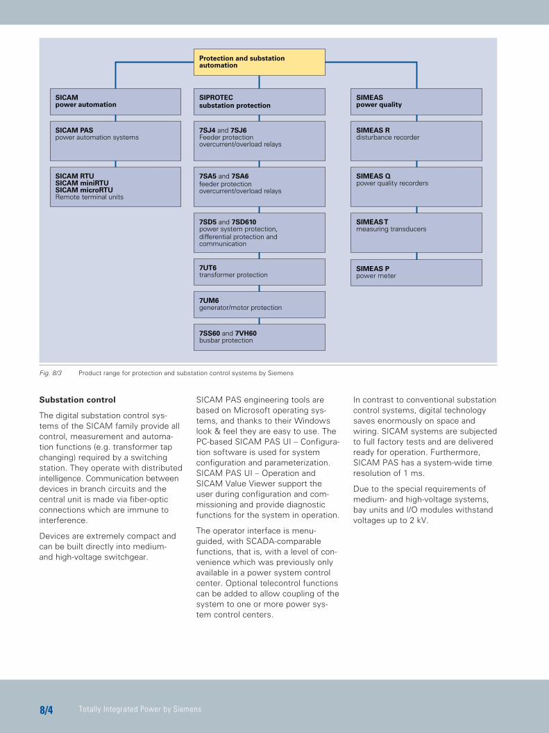
SICAMpower automation
SIPROTECsubstation protection
SICAM PASpower automation systems
7SJ4 and 7SJ6Feeder protectionovercurrent/overload relays
7SA5 and 7SA6feeder protectionovercurrent/overload relays
7SS60 and 7VH60busbar protection
7UM6generator/motor protection
7UT6transformer protection
Protection and substationautomation
SIMEAS Rdisturbance recorder
SIMEAS Qpower quality recorders
SIMEAS Tmeasuring transducers
7SD5 and 7SD610power system protection,differential protection andcommunication
SICAM RTUSICAM miniRTUSICAM microRTURemote terminal units
SIMEASpower quality
SIMEAS Ppower meter
Fig. 8/3 Product range for protection and substation control systems by Siemens
TIP_Kap_08_Engl 11.08.2005 19:36 Uhr Seite 4
Protection and Substation Control
88/5
Remote Terminal Units
Siemens RTU’s fulfill all the classicfunctions of remote measurementand control. Furthermore, they pro-vide comprehensive data pre-pro-cessing of operational and fault infor-mation, and automating functionsthat are based on powerful micro-processors.
In the classic case, connections tothe switchgear are made throughcoupling relays and transducers. Thismethod allows an economically favor-able solution when modernizing or renewing control systems in older installations. Alternatively, especiallyfor new installations, direct connec-tion is also possible. Digital protec-tion devices can be connected by serial links through fiber-optic conductors or bus systems.
Switchgear interlocking
The distributed substation controlsystem SICAM PAS provides the option to implement bay-specific and‘inter-bay’ interlocking by means ofon-screen graphic planning. The substation topology as well as in-feed conditions are taken into consideration. It prevents falseswitching, thus enhancing the safety of operating personnel and equipment considerably.
Power quality (measuring and recording)
The SIMEAS® product range offersequipment for the monitoring ofpower supply quality (harmonic content, distortion factor, peak loads,power factor, etc.), fault recorders(oscillostores), and measuring transducers.
Stored data can be transmitted manually or automatically to PC evaluation systems where they canbe analyzed by intelligent programs.Expert systems are also applied here.This leads to rapid fault analysis andvaluable indicators for the improve-ment of network reliability.
For local bulk data storage and transmission, the central processorDAKON can be installed at substationlevel. Data transmission circuits foranalog telephone or digital ISDN net-works are incorporated as standard.Connection to local or wide-area net-works (LAN, WAN) is equally possi-ble. We can also offer the SIMEAS Tseries of compact and powerful
measuring transducers with analogand digital outputs.
Advantages for the user
The concept of the “entire technol-ogy from one partner” offers theuser many advantages: C High-level security for his systems
and operational rationalization possibilities
C Powerful system solutions with the most modern technology
C Compliance with international standards
C Integration in the overall system SIPROTEC®– SICAM®– SIMATIC®
C Space and cost savings C Integration of many functions into
one unit and compact equipmentpackaging
C Simple planning and safe operation C Homogeneous design, matched
interfaces and EMI security throughout
C Rationalized programming and handling
TIP_Kap_08_Engl 11.08.2005 19:36 Uhr Seite 5
Totally Integrated Power by Siemens8/6
C Windows-based PC tools and standardized displays
C Fast, flexible mounting and reduced wiring
C Simple, fast commissioning C Efficient spare part stocking,
high flexibility C High-level operational safety
and availability C Continuous self-monitoring and
proven technology: C 20 years of digital relay
experience (more than 350,000units in operation)
C 15 years of digital substation control (more than 3,000 systems in operation)
C Rapid problem solving C Comprehensive support and
fast response from local sales and workshop facilities worldwide
Application notes All devices and systems for protec-tion, metering and control mentionedherein are designed to be used in thearduous environment of electricalsubstations, power plants and thevarious industrial application areas.
When the devices were developed,special emphasis was placed on thedesign of electromechanical interfer-ence (EMI). The devices are in accor-dance with IEC 60255 standards. Detailed information is contained inthe device manuals.
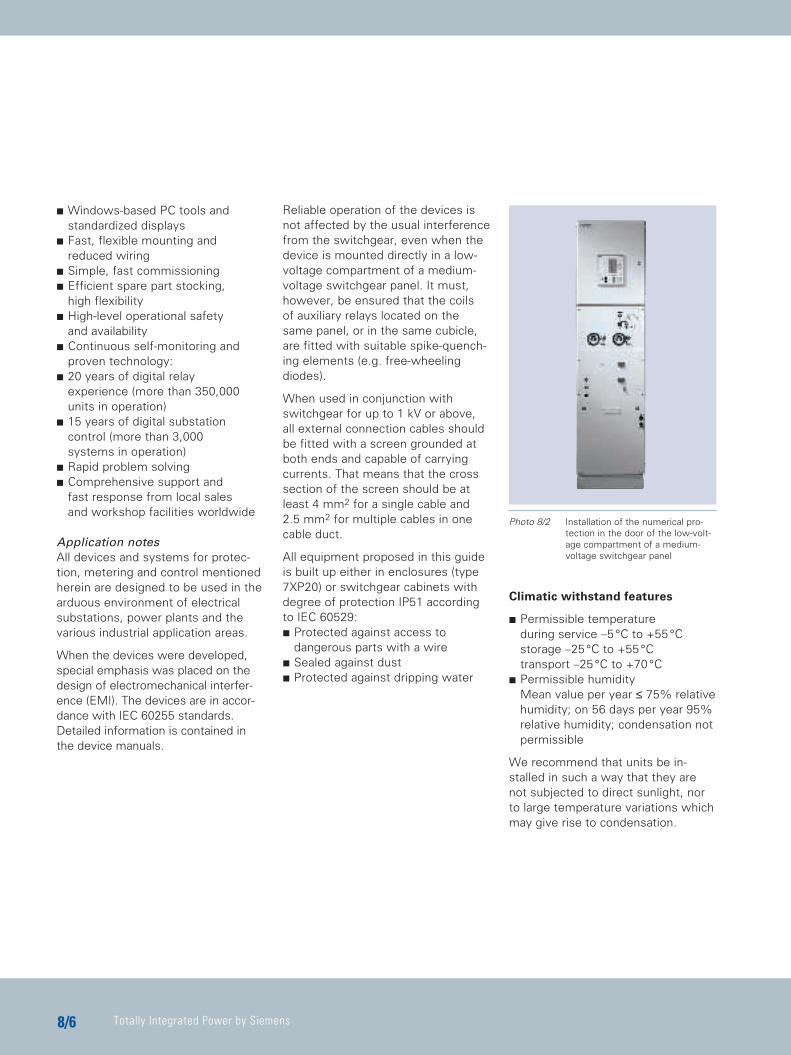
Reliable operation of the devices isnot affected by the usual interferencefrom the switchgear, even when thedevice is mounted directly in a low-voltage compartment of a medium-voltage switchgear panel. It must,however, be ensured that the coils of auxiliary relays located on thesame panel, or in the same cubicle,are fitted with suitable spike-quench-ing elements (e.g. free-wheelingdiodes).
When used in conjunction withswitchgear for up to 1 kV or above,all external connection cables shouldbe fitted with a screen grounded atboth ends and capable of carryingcurrents. That means that the crosssection of the screen should be atleast 4 mm2 for a single cable and2.5 mm2 for multiple cables in onecable duct.
All equipment proposed in this guideis built up either in enclosures (type7XP20) or switchgear cabinets withdegree of protection IP51 accordingto IEC 60529: C Protected against access to
dangerous parts with a wireC Sealed against dust C Protected against dripping water
Climatic withstand features
C Permissible temperature during service –5°C to +55°Cstorage –25°C to +55°Ctransport –25°C to +70°C
C Permissible humidity Mean value per year ≤ 75% relativehumidity; on 56 days per year 95%relative humidity; condensation notpermissible
We recommend that units be in-stalled in such a way that they arenot subjected to direct sunlight, norto large temperature variations whichmay give rise to condensation.
Photo 8/2 Installation of the numerical pro-tection in the door of the low-volt-age compartment of a medium-voltage switchgear panel
TIP_Kap_08_Engl 11.08.2005 19:36 Uhr Seite 6
Protection and Substation Control
88/7
Mechanical stress
Vibration and shock during operation C Standards:
IEC 60255-21 and IEC 60068-2 C Vibration
– sinusoidal IEC 60255-21-1, class 110 Hz to 60 Hz: ± 0.035 mm amplitude; IEC 60068-2-6 60 Hz to 150 Hz: 0.5 g acceleration sweep rate 10 octaves/min 20 cycles in 3 orthogonal axes
Vibration and shock during transport C Standards:
IEC 60255-21 and IEC 60068-2 C Vibration
– sinusoidal IEC 60255-21-1, class 2 5 Hz to 8 Hz: ± 7.5 mm amplitude; IEC 60068-2-6 8 Hz to 150 Hz: 2 g acceleration sweep rate 1 octave/min 20 cycles in 3 orthogonal axes
C Shock IEC 60255-21-2, class 1 IEC 60068-2-27
Insulation tests
C Standards: IEC 60255-5 – High-voltage test (routine test) 2 kV (rms), 50 Hz – Impulse voltage withstand test(type test) all circuits, class III 5 kV (peak); 1.2/50 µs; 0.5 J; 3 positive and 3 negative shots at intervals of 5 s
Electromagnetic compatibility
EU conformity declaration (CE mark)All Siemens protection and controlproducts recommended in this man-ual comply with the EMC Directive99/336/EEC of the Council of the European Community and further relevant IEC 255 standards on electromagnetic compatibility.
All products carry the CE mark.
EMC tests; immunity (type tests)
C Standards: IEC 60255-22 (product standard) EN 50082-2 (generic standard)
C High frequency IEC 60255-22-1 class III– 2.5 kV (peak); 1 MHz; τ = 15 µs; 400 shots/s; duration 2 s
C Electrostatic discharge IEC 60255-22-2 class III and EN 61000-4-2 class III – 4 kV contact discharge; 8 kV air discharge; both polarities; 150 pF; Ri = 330 ohm
C High-frequency electromagneticfield, non-modulated; IEC 60255-22-3 (report) class III – 10 V/m; 27 MHz to 500 MHz
C High-frequency electromagneticfield, amplitude-modulated; ENV 50140, class III – 10 V/m; 80 MHz to 1,000 MHz, 80%; 1 kHz; AM
C High-frequency electromagneticfield, pulse-modulated; ENV 50140/ENV 50204, class III – 10 V/m; 900 MHz; repetition frequency 200 Hz; duty cycle 50%
C Fast transients IEC 60255-22-4 and EN 61000-4-4, class III – 2 kV; 5/50 ns; 5 kHz; burst length 15 ms; repetition rate 300 ms; both polarities; Ri = 50 ohm; duration 1 min
C Conducted disturbances inducedby radio-frequency fields HF, amplitude-modulated ENV 50141, class III – 10 V; 150 kHz to 80 MHz; 80%; 1 kHz; AM
C Power-frequency magnetic field EN 61000-4-8, class IV – 30 A/m continuous; 300 A/m for 3 s; 50 Hz
EMC tests; emission (type tests)
C Standard: EN 50081-2 (generic standard)
C Interference field strength CISPR11, EN 55011, class A 30 MHz to100 MHz
C Conducted interference voltage,aux. voltage CISPR 22, EN 55022,class B – 150 kHz to 30 MHz
TIP_Kap_08_Engl 11.08.2005 19:36 Uhr Seite 7
Totally Integrated Power by Siemens8/8
Instrument transformers
Instrument transformers must complywith the applicable IEC recommenda-tions IEC 60044, formerly IEC 60185(current transformers) and 186 (potential transformers), ANSI/IEEEC57.13 or other comparable standards.
Potential transformers
Potential transformers (p.t.) in singleor double-pole design for all primaryvoltages have single or dual second-ary windings of 100, 110 or 120 V/KL3,with output ratings between 10 and300 VA, and accuracies of 0.2, 0.5 or1% to suit the particular application.
Current transformers
Current transformers (c.t.) are usuallyof the single-ratio type with wound orbar-type primaries of adequate ther-mal rating. Single, dual or triple sec-ondary windings of 1 or 5 A are stan-dard.
1 A rating, however, should be pre-ferred, particularly in HV and EHV sta-tions, to reduce the burden of theconnecting leads. Output power(rated burden in VA), accuracy andsaturation characteristics (accuracy-limiting factor) of the cores and sec-ondary windings must meet the par-ticular application.
The current transformer classificationcode of IEC is used in the following:
Measuring coresThey are normally specified with0.5% or 1.0 % accuracy (class 0.5 Mor 1.0 M), and an accuracy limitingfactor of 5 or 10. The required outputpower (rated burden) must be higherthan the actually connected burden.Typical values are 5, 10, 15 VA.Higher values are normally not neces-sary when only electronic meters andrecorders are connected.
A typical specification could be: 0.5 M 10, 15 VA.
Cores revenue meteringIn this case, class 0.2 M is normallyrequired.
Protection coresThe size of the protection core de-pends mainly on the maximum short-circuit current and the total burden(internal c.t. burden, plus burden ofconnecting leads, plus relay burden).
Further, an overdimensioning factorhas to be considered to cover the in-fluence of the DC component in theshort-circuit current.
In general, an accuracy of 1% (class5 P) is specified. The accuracy limit-ing factor KSSC should normally bedesigned so that at least the maxi-mum short-circuit current can betransmitted without saturation (DC component not considered).
This results, as a rule, in rated accu-racy limiting factors of 10 or 20 de-pendent on the rated burden of thecurrent transformer in relation to theconnected burden. A typical specifi-cation for protection cores for distri-bution feeders is 5P10, 15 VA or5P20, 10 VA.
The requirements for protective cur-rent transformers for transient per-formance are specified in IEC 60044-6.
In many practical cases, the currenttransformers cannot be designed toavoid saturation under all circum-stances because of cost and spacereasons, particularly with metal-en-closed switchgear.
The Siemens relays are therefore de-signed to tolerate current transformersaturation to a large extent. The nu-merical relays proposed in this guideare particularly stable in this case dueto their integral saturation detectionfunction.
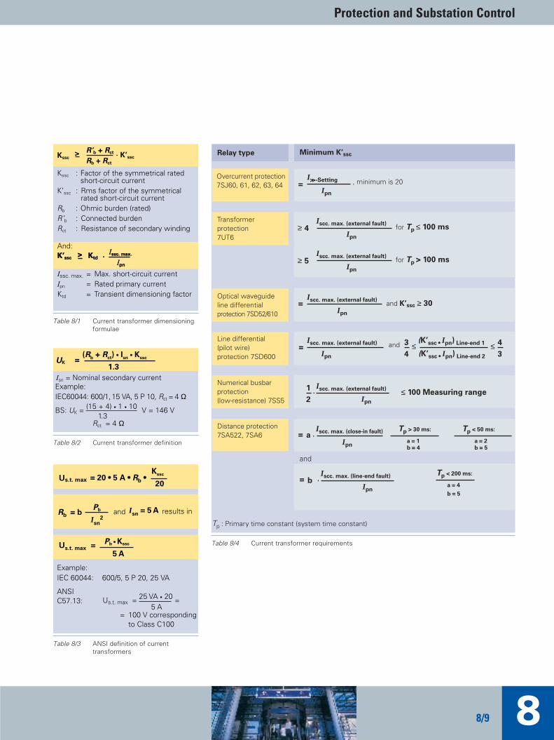
The required current transformer accuracy- limiting factor K’ssc can bedetermined by calculation, as shownin Table 8/4.
The transient rated dimensioning factor Ktd depends on the type of relay and the primary DC time con-stant. For the normal case, withshort-circuit time constants lowerthan 100 ms, the necessary value forK’ssc can be taken from Table 8/1.
TIP_Kap_08_Engl 11.08.2005 19:36 Uhr Seite 8
Protection and Substation Control
88/9
Kssc : Factor of the symmetrical rated short-circuit current
K’ssc : Rms factor of the symmetrical rated short-circuit current
Rb : Ohmic burden (rated)R’b : Connected burdenRct : Resistance of secondary winding
Issc. max. = Max. short-circuit currentIpn = Rated primary currentKtd = Transient dimensioning factor
R’b + Rct
Rb + Rct
Kssc> K’ssc
Issc. max.K’ssc>
Ipn
Ktd
And:Issc. max.K’ssc
>Ipn
Ktd
Example:IEC60044: 600/1, 15 VA, 5 P 10, Rct = 4 Ω
(Rb + Rct) • Isn • KsscUK =
1.3
BS: UK = (15 + 4) • 1 • 10 V = 146 V1.3
Rct = 4 Ω
Isn = Nominal secondary current
Example:IEC 60044: 600/5, 5 P 20, 25 VA
20Us.t. max = 20 • 5 A • Rb •
Kssc
Rb = b Pb
Isn
2and I
sn = 5 A results in
Us.t. max = Pb • Kssc
5 A
Us.t. max = 25 VA • 20 =5 A
ANSIC57.13:
= 100 V correspondingto Class C100
Table 8/4 Current transformer requirements
Relay type Minimum K’ssc
Overcurrent protection7SJ60, 61, 62, 63, 64 , minimum is 20
I>>-Setting
Ipn
Transformerprotection7UT6
Optical waveguideline differentialprotection 7SD52/610
and
I scc. max. (close-in fault)
Ipn
aDistance protection7SA522, 7SA6
I scc. max. (line-end fault)
Ipn
b
I scc. max. (external fault)
Ipn
Numerical busbarprotection(low-resistance) 7SS5
=
=
=
=
≥
1
2
andI scc. max. (external fault)
Ipn
(K’ssc • Ipn) Line-end 1
(K’ssc • Ipn) Line-end 2
3
4=
Tp < 50 ms:
a = 2
b = 5
Tp < 200 ms:
a = 4
b = 5
Line differential(pilot wire)protection 7SD600
4I scc. max. (external fault)
Ipn
for Tp ≤ 100 ms
≥ 5I scc. max. (external fault)
Ipn
for Tp > 100 ms
≤ 100 Measuring range
I scc. max. (external fault)
Ipn
and K’ssc ≥ 30
≤ ≤ 4
3
Tp > 30 ms:
a = 1
b = 4
Tp : Primary time constant (system time constant)
Table 8/3 ANSI definition of current transformers
Table 8/2 Current transformer definition
Table 8/1 Current transformer dimensioningformulae
TIP_Kap_08_Engl 11.08.2005 19:36 Uhr Seite 9
Totally Integrated Power by Siemens8/10
Relay burden
The current transformer burdens ofthe numerical relays of Siemens arebelow 0.1 VA and can therefore beneglected for a practical estimation.Exceptions are the 7SS60 busbar protection (2 VA) and the pilot wirerelays, 7SD600 (4 VA).
Normally, intermediate current trans-formers needn't be used any more,as the ratio adaptation for busbar andtransformer protection is numericallyperformed in the relay.
Analog static relays in general alsohave burdens below about 1 VA.
Mechanical relays, however, have amuch higher burden, up to the orderof 10 VA. This has to be consideredwhen older relays are connected tothe same current transformer circuit.In any case, the relevant relay manu-als should always be consulted forthe actual burden values.
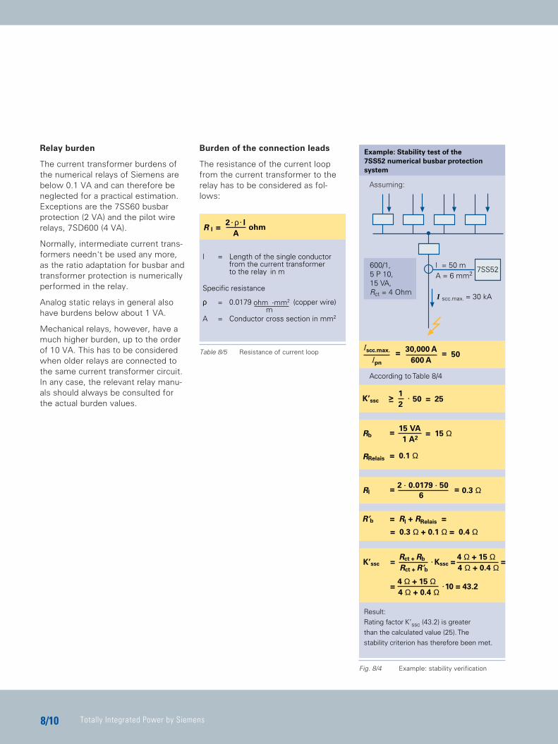
Burden of the connection leads
The resistance of the current loopfrom the current transformer to therelay has to be considered as fol-lows:
2K’ssc >
150 = 25
7SS52
I scc.max. = 30 kA
l = 50 mA = 6 mm2
600/1,5 P 10,15 VA,Rct = 4 Ohm
50=Iscc.max.
Ipn
30,000 A
600 A=
Result:
Rating factor K’ssc (43.2) is greater
than the calculated value (25). The
stability criterion has therefore been met.
Rl6
=2 0.0179 50
0.3 Ω=
R’b = Rl + RRelais =
= 0.3 Ω + 0.1 Ω = 0.4 Ω
Assuming:
According to Table 8/4
Rct + R’bK’ssc
Rct + RbKssc =
1 A2Rb =
15 VA= 15 Ω
RRelais = 0.1 Ω
Example: Stability test of the7SS52 numerical busbar protectionsystem
4 Ω + 0.4 Ω4 Ω + 15 Ω
=4 Ω + 0.4 Ω4 Ω + 15 Ω
10 = 43.2
==
AR l =
2 ρ lohm
l = Length of the single conductorfrom the current transformerto the relay in m
Specific resistance
ρ = 0.0179 (copper wire)
A = Conductor cross section in mm2
ohm mm2
m
Table 8/5 Resistance of current loop
Fig. 8/4 Example: stability verification
TIP_Kap_08_Engl 11.08.2005 19:36 Uhr Seite 10

Protection and Substation Control
88/11
8.1 Power SystemProtectionIntroduction
Siemens is one of the world‘s leadingsuppliers of protective equipment forpower systems.
Thousands of relays ensure first-classperformance in the transmission anddistribution networks on all voltagelevels all over the world, in countriesof tropical heat and arctic frost.
For many years, Siemens has alsosignificantly influenced the develop-ment of protection technology.
In 1976, the first minicomputer(process-computer)-based protectionsystem was commissioned: A totalof 10 systems for 110/20-kV substa-tions were supplied that are stillworking at their customers' full satisfaction today.
In 1985, we were the first to producea series of fully numerically con-trolled relays with standardized com-munication interfaces.
Today, Siemens offers a completeprogram of protective relays for allapplications including numerical busbar protection.
To date, more than 350,000 numeri-cal protection relays from Siemensare providing successful service, asstand-alone devices in traditional systems or as components of coordi-nated protection and substation control.
Meanwhile, the innovative SIPROTEC 4series has been launched, incorporat-ing the many years of operational experience with thousands of relaysas well as the awareness of user requirements (power company rec-ommendations).
State of the art
Mechanical and solid-state (static) relays have been almost completelyphased out of our production be-cause numerical relays are now preferred by the users.
Advantages
C Compact design and lower costdue to the integration of manyfunctions into one relay
C High availability even with lessmaintenance owing to integratedself-monitoring
C No drift (ageing) of the measuringcharacteristics because of theircomplete digital processing
C High availability even with lessmaintenance due to digital filtering and optimized measuring algorithms
C Many integrated add-on functions,for example for load monitoringand event/fault recording
C Local operation keypad and displaydesigned to modern ergonomic criteria
C Easy and secure reading of information via serial interfaceswith a PC, locally or by remote access
C Possibility to communicate withhigher-level control systems using standardized protocols (open communication)
Modern protection management
All the functions, for example, of apower system protection schemecan be incorporated in one unit:C Distance protection with associated
add-on and monitoring functionsC Universal teleprotection interface C Auto-reclose and synchro-check
Photo 8/3 SIPROTEC 4 numerical relays bySiemens
TIP_Kap_08_Engl 11.08.2005 19:42 Uhr Seite 11
Totally Integrated Power by Siemens8/12
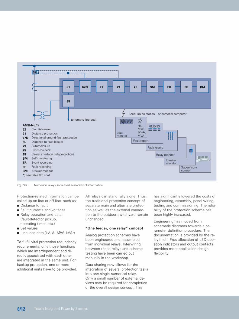
Protection-related information can becalled up on-line or off-line, such as:C Distance to faultC Fault currents and voltagesC Relay operation and data
(fault-detector pickup, operating times etc.)
C Set valuesC Line load data (kV, A, MW, kVAr)
To fulfill vital protection redundancyrequirements, only those functionswhich are interdependent and di-rectly associated with each other are integrated in the same unit. Forbackup protection, one or more additional units have to be provided.
All relays can stand fully alone. Thus,the traditional protection concept ofseparate main and alternate protec-tion as well as the external connec-tion to the outdoor switchyard remainunchanged.
“One feeder, one relay” concept
Analog protection schemes havebeen engineered and assembledfrom individual relays. Interwiring between these relays and schemetesting have been carried out manually in the workshop.
Data sharing now allows for the integration of several protection tasksinto one single numerical relay. Only a small number of external de-vices may be required for completionof the overall design concept. This
has significantly lowered the costs ofengineering, assembly, panel wiring,testing and commissioning. The relia-bility of the protection scheme hasbeen highly increased.
Engineering has moved fromschematic diagrams towards a pa-rameter definition procedure. Thedocumentation is provided by the re-lay itself. Free allocation of LED oper-ation indicators and output contactsprovides more application designflexibility.
Relay monitor
01.10.93
BM
Serial link to station – or personal computer
SM ER FR2579FL67N21
to remote line end kA,kV,Hz,MW,MVAr,MVA
85
Loadmonitor
52
ANSI-No.*)522167NFL792585SMERFRBM*) see Table 8/6 cont.
Circuit-breakerDistance protectionDirectional ground-fault protectionDistance-to-fault locatorAutoreclosureSynchro-checkCarrier interface (teleprotection)Self-monitoringEvent recordingFault recordingBreaker monitor
Fault record
Fault report
Breakermonitor
Supervisorycontrol
Fig. 8/5 Numerical relays, increased availability of information
TIP_Kap_08_Engl 11.08.2005 19:42 Uhr Seite 12
Protection and Substation Control
88/13
Measuring function included
The additional transducer was ratherused for protecting measuring instru-ments under system fault conditions.Due to the low thermal withstand ca-pability of the measuring instruments,they could not be connected to theprotective current transformer directly.When numerical protection technol-ogy is employed, protective currenttransformers are in many cases accu-rate enough to take operationalmeasurements. Consequently, addi-tional transducers and measuring in-struments are now only necessarywhere high accuracy is required, e.g.for metering used for electricity bills.
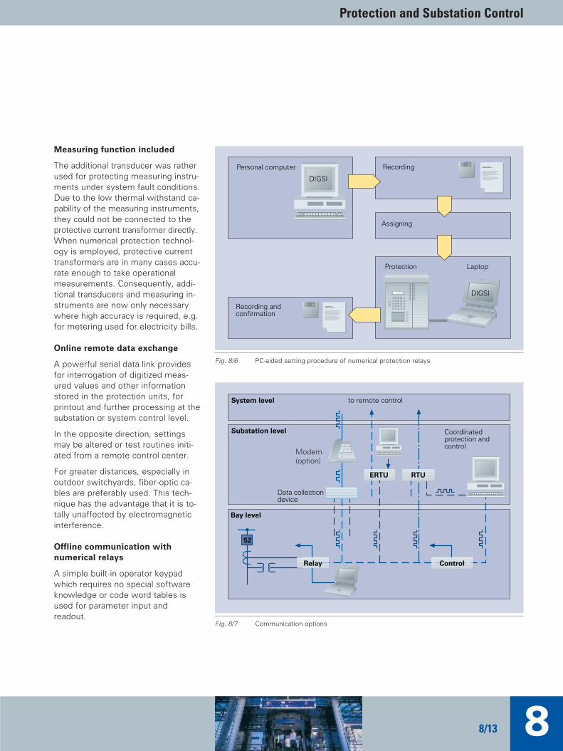
Online remote data exchange
A powerful serial data link providesfor interrogation of digitized meas-ured values and other informationstored in the protection units, forprintout and further processing at thesubstation or system control level.
In the opposite direction, settingsmay be altered or test routines initi-ated from a remote control center.
For greater distances, especially inoutdoor switchyards, fiber-optic ca-bles are preferably used. This tech-nique has the advantage that it is to-tally unaffected by electromagneticinterference.
Offline communication with numerical relays
A simple built-in operator keypadwhich requires no special softwareknowledge or code word tables isused for parameter input and readout.
Protection Laptop
RecordingPersonal computer
Assigning
Recording andconfirmation
DIGSI
DIGSI
System level to remote control
Substation level
Modem(option)
Bay level
Data collectiondevice
ERTU
Control
Coordinatedprotection andcontrol
RTU
Relay
52
Fig. 8/7 Communication options
Fig. 8/6 PC-aided setting procedure of numerical protection relays
TIP_Kap_08_Engl 11.08.2005 19:42 Uhr Seite 13
Totally Integrated Power by Siemens8/14
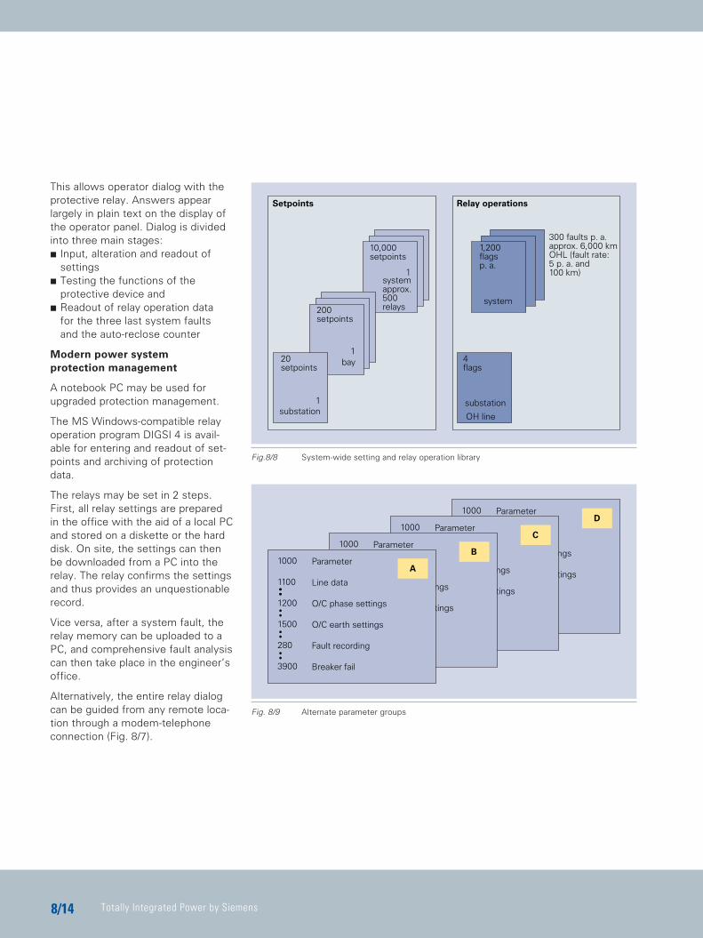
This allows operator dialog with theprotective relay. Answers appearlargely in plain text on the display ofthe operator panel. Dialog is dividedinto three main stages:C Input, alteration and readout of
settingsC Testing the functions of the
protective device andC Readout of relay operation data
for the three last system faults and the auto-reclose counter
Modern power system protection management
A notebook PC may be used for upgraded protection management.
The MS Windows-compatible relayoperation program DIGSI 4 is avail-able for entering and readout of set-points and archiving of protectiondata.
The relays may be set in 2 steps.First, all relay settings are prepared in the office with the aid of a local PCand stored on a diskette or the harddisk. On site, the settings can thenbe downloaded from a PC into the relay. The relay confirms the settingsand thus provides an unquestionablerecord.
Vice versa, after a system fault, therelay memory can be uploaded to aPC, and comprehensive fault analysiscan then take place in the engineer’soffice.
Alternatively, the entire relay dialogcan be guided from any remote loca-tion through a modem-telephone connection (Fig. 8/7).
10,000setpoints
200setpoints
bay
substation
20setpoints
substation
4flags
OH line
1,200flagsp. a.
system
1
1
1
300 faults p. a.approx. 6,000 kmOHL (fault rate:5 p. a. and100 km)
systemapprox.500relays
Relay operationsSetpoints
Fig.8/8 System-wide setting and relay operation library
Fig. 8/9 Alternate parameter groups
Parameter
Line data
O/C Phase settings
O/C Ground settings
Fault recording
Breaker fail
1000
1100
1200
1500
280
3900
DParameter
Line data
O/C Phase settings
O/C Ground settings
Fault recording
Breaker fail
1000
1100
1200
1500
280
3900
CParameter
Line data
O/C Phase settings
O/C Ground settings
Fault recording
Breaker fail
1000
1100
1200
1500
280
3900
BParameter
Line data
O/C phase settings
O/C earth settings
Fault recording
Breaker fail
1000
1100
1200
1500
280
3900
A
TIP_Kap_08_Engl 11.08.2005 19:42 Uhr Seite 14
Protection and Substation Control
88/15
Relay data management
Analog distribution-type relays havesome 20–30 setpoints. If we con-sider a power system with about 500relays, then the number adds up to10,000 settings. This requires consid-erable expenditure in setting the relays and filing retrieval setpoints.
A personal computer-aided man-ma-chine dialog and archiving program,e.g. DIGSI 4, assists the relay engi-neer in data filing and retrieval.
The program files all settings system-atically in substation-feeder-relay order.
Corrective rather than preventivemaintenance
Numerical relays monitor their ownhardware and software. Exhaustiveself-monitoring and failure diagnosticroutines are not restricted to the pro-tective relay itself, but are methodi-cally carried through from currenttransformer circuits to tripping relaycoils.
Equipment failures and faults in thecurrent transformer circuits are im-mediately recorded and signaled.
Thus, the service personnel are nowable to correct the failure upon occur-rence, resulting in a significantly up-graded availability of the protectionsystem.
Adaptive relaying
Numerical relays now offer secure,convenient and comprehensive ad-justment to changing conditions. Adjustments may be initiated eitherby the relay’s own intelligence orfrom outside via contacts or serialtelegrams. Modern numerical relayscontain a number of parameter setsthat can be pre-tested during com-missioning of the scheme (Fig. 8/9).One set is normally operative. Trans-fer to the other sets can be con-trolled via binary inputs or serial datalink. There are a number of applica-tions for which multiple settinggroups can upgrade the scheme performance, for example:
a) For use as a voltage-dependentcontrol of o/c relay pickup values to overcome alternator fault currentdecrement to below normal loadcurrent when the AVR is not in automatic operation.
b) For maintaining short operation times with lower fault currents, e.g. automatic change of settings if one supply transformer is taken out of service.
c) For “switch-onto-fault” protection to provide shorter time settings when energizing a circuit after maintenance. The normal settings can be restored automatically after a time delay.
d) For auto-reclose programs, i.e. instantaneous operation for first trip and delayed operation after unsuccessful reclosure.
e) For cold load pickup problems where high starting currents may cause relay operation.
f) For ”ring open“ or ”ring closed“ operation.
TIP_Kap_08_Engl 11.08.2005 19:42 Uhr Seite 15
Totally Integrated Power by Siemens8/16
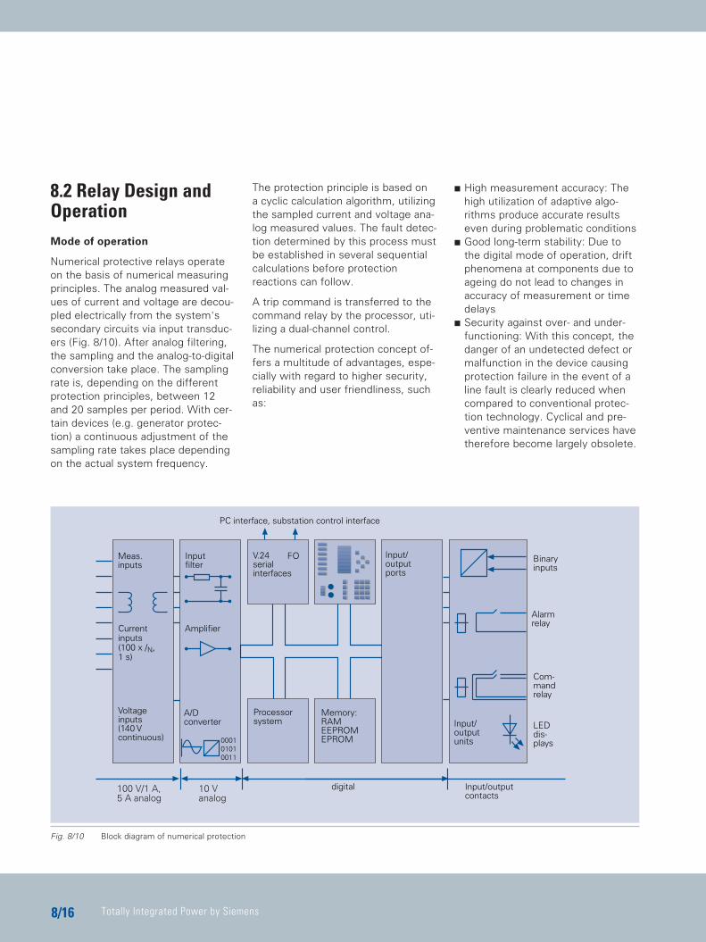
8.2 Relay Design andOperationMode of operation
Numerical protective relays operateon the basis of numerical measuringprinciples. The analog measured val-ues of current and voltage are decou-pled electrically from the system'ssecondary circuits via input transduc-ers (Fig. 8/10). After analog filtering,the sampling and the analog-to-digitalconversion take place. The samplingrate is, depending on the differentprotection principles, between 12and 20 samples per period. With cer-tain devices (e.g. generator protec-tion) a continuous adjustment of thesampling rate takes place dependingon the actual system frequency.
The protection principle is based on a cyclic calculation algorithm, utilizingthe sampled current and voltage ana-log measured values. The fault detec-tion determined by this process mustbe established in several sequentialcalculations before protection reactions can follow.
A trip command is transferred to thecommand relay by the processor, uti-lizing a dual-channel control.
The numerical protection concept of-fers a multitude of advantages, espe-cially with regard to higher security,reliability and user friendliness, suchas:
C High measurement accuracy: Thehigh utilization of adaptive algo-rithms produce accurate resultseven during problematic conditions
C Good long-term stability: Due to the digital mode of operation, drift phenomena at components due to ageing do not lead to changes in accuracy of measurement or time delays
C Security against over- and under-functioning: With this concept, the danger of an undetected defect or malfunction in the device causing protection failure in the event of a line fault is clearly reduced when compared to conventional protec-tion technology. Cyclical and pre-ventive maintenance services have therefore become largely obsolete.
Meas.inputs
Currentinputs(100 x /N,1 s)
Voltageinputs(140 Vcontinuous)
A/Dconverter
Processorsystem
Inputfilter
V.24serialinterfaces
PC interface, substation control interface
Memory:RAMEEPROMEPROM
Input/outputports
Input/outputunits
Binaryinputs
Alarmrelay
Com-mandrelay
LEDdis-plays0001
01010011
Amplifier
Input/outputcontacts
digital10 Vanalog
100 V/1 A,5 A analog
FO
Fig. 8/10 Block diagram of numerical protection
TIP_Kap_08_Engl 11.08.2005 19:42 Uhr Seite 16
Protection and Substation Control
88/17
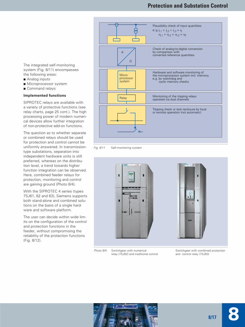
The integrated self-monitoring system (Fig. 8/11) encompasses the following areas:C Analog inputsC Microprocessor systemC Command relays
Implemented functions
SIPROTEC relays are available with a variety of protective functions (seerelay charts, page 25 cont.). The highprocessing power of modern numeri-cal devices allow further integrationof non-protective add-on functions.
The question as to whether separateor combined relays should be usedfor protection and control cannot beuniformly answered. In transmission-type substations, separation into independent hardware units is stillpreferred, whereas on the distribu-tion level, a trend towards higherfunction integration can be observed.Here, combined feeder relays for protection, monitoring and control are gaining ground (Photo 8/4).
With the SIPROTEC 4 series (types7SJ61, 62 and 63), Siemens supportsboth stand-alone and combined solu-tions on the basis of a single hard-ware and software platform.
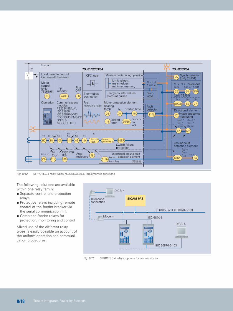
The user can decide within wide lim-its on the configuration of the controland protection functions in thefeeder, without compromising the reliability of the protection functions(Fig. 8/12).
Plausibility check of input quantitiese. g.iL1 + iL2 + iL3 = iE
uL1 + uL2 + uL3 = uE
Check of analog-to-digital conversionby comparison withconverted reference quantities
A
D
Hardware and software monitoring ofthe microprocessor system incl. memory,e.g. by watchdog and
cyclic memory checks
Micro-processorsystem
Monitoring of the tripping relaysoperated via dual channelsRelay
Tripping check or test reclosure by localor remote operation (not automatic)
Fig. 8/11 Self-monitoring system
Photo 8/4 Switchgear with numerical Switchgear with combined protection relay (7SJ62) and traditional control and control relay (7SJ63)
TIP_Kap_08_Engl 11.08.2005 19:43 Uhr Seite 17
Totally Integrated Power by Siemens8/18
The following solutions are availablewithin one relay family:C Separate control and protection
relays C Protective relays including remote
control of the feeder breaker viathe serial communication link
C Combined feeder relays for protection, monitoring and control
Mixed use of the different relaytypes is easily possible on account ofthe uniform operation and communi-cation procedures.
SICAM PAS
DIGSI 4
Telephoneconnection
IEC 61850 or IEC 60870-5-103
Modem IEC 6870-5
IEC 60870-5-103
DIGSI 4
Busbar
Local, remote controlCommand/checkback
52 7SJ61/62/63/64 7SJ62/63/64
CFC logic Measurements during operation
Limit values,mean values,min/max memory
Synchronization(only 7SJ64)
(only 7SJ64)
Motorcontrol(only7SJ63/64)
Tripmonitor
FinalOFF
Thermoboxconnection
Energy counter valuesas count pulses
calcu-lated
Operation CommunicationsmodulesRS232/485/LWLIEC 61850ICE 60870-5-103PROFIBUS FMS/DPDNP3.0MODBUS RTU
I< Startup time
Faultrecording logic Bearing
temp.
Lockedrotor
Switch-onlock
Faultdetector Directional element
Phase-sequencemonitoring
Ground faultdetection element
Directional ground faultdetection element
High-imp.diff. Auto-
reclosure
Inrushlock
Interm.ground fault
Switch failureprotection
Motor protection element
U, f, P element
Fig. 8/12 SIPROTEC 4 relay types 7SJ61/62/63/64, implemented functions
Fig. 8/13 SIPROTEC 4 relays, options for communication
TIP_Kap_08_Engl 11.08.2005 19:43 Uhr Seite 18
Protection and Substation Control
88/19
Integration of relays intosubstation control
Basically, all Siemens numerical relays are equipped with an an inter-face acc. to IEC 60870-5-103 foropen communication with substationcontrol systems either by Siemens(SICAM) or by any other supplier. Therelays of the latest SIPROTEC 4 se-ries, however, are even more flexibleand equipped with several communi-cation options. SIPROTEC 4 relayscan still be connected to the SICAM system or to a communications system of another supplier via IEC 60870-5-103.
SIPROTEC 4 protection systems andSICAM substation control technologyhave a uniform design. Communica-tion is based on the PROFIBUSstandard.
IEC 61850 has been established as a global standard by users and manu-facturers. The agreed objective ofthis standard is to create a compre-hensive communications solution forsubstations. Thus, the user is pro-vided with open communication sys-tems which are based on Ethernettechnology.
SIPROTEC protective relays and baycontrol units are the first devices re-leased in mid 2004 which use a com-munications protocol in compliancewith IEC 61850. The station configu-rator, which is part of the DIGSI 4 operating software, can be used toconfigure SIPROTEC relays as well as non-Siemens relays via IEC 61850.
SICAM PAS, the new substation control system by Siemens has beendesigned as an open system whichemploys IEC 61580 as communica-tion standard between the bay andstation control level. IEC 61580 sup-ports interoperability and integrationof substation control systems which facilitates system engineering inde-pendent of the manufacturer and reduces the planning expense at the same time.
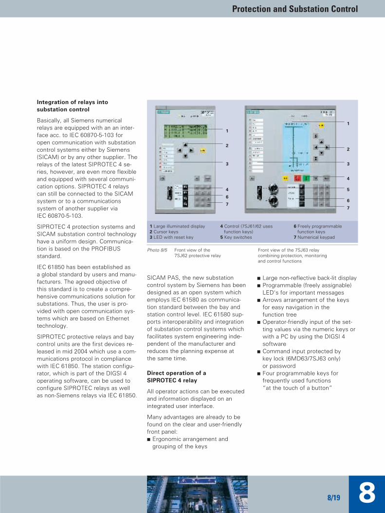
Direct operation of a SIPROTEC 4 relay
All operator actions can be executedand information displayed on an integrated user interface.
Many advantages are already to befound on the clear and user-friendlyfront panel:C Ergonomic arrangement and
grouping of the keys
C Large non-reflective back-lit displayC Programmable (freely assignable)
LED's for important messagesC Arrows arrangement of the keys
for easy navigation in the function tree
C Operator-friendly input of the set-ting values via the numeric keys orwith a PC by using the DIGSI 4 software
C Command input protected bykey lock (6MD63/7SJ63 only) or password
C Four programmable keys forfrequently used functions “at the touch of a button”
Photo 8/5 Front view of the Front view of the 7SJ63 relay 7SJ62 protective relay combining protection, monitoring
and control functions
1 Large illuminated display2 Cursor keys3 LED with reset key
4 Control (7SJ61/62 usesfunction keys)
5 Key switches
6 Freely programmablefunction keys
7 Numerical keypad
1
2
3
4
6
7
1
2
3
4
5
6
7
TIP_Kap_08_Engl 11.08.2005 19:43 Uhr Seite 19

Totally Integrated Power by Siemens8/20
DIGSI 4 – the operating soft-ware for all SIPROTEC relays
For the user, DIGSI is synonymouswith convenient, user-friendly para-meterizing and operation of numeri-cal protection relays. DIGSI 4 is a log-ical innovation for operation of pro-tection and bay control units of theSIPROTEC 4 family.
The PC software DIGSI 4 is the hu-man-machine interface between theuser and the SIPROTEC 4 units. Itfeatures modern, intuitive operatingprocedures. With DIGSI 4, theSIPROTEC 4 units can be configuredand queried.
C The interface provides you onlywith what is really necessary, irrespective of which unit you are currently configuring.
C Contextual menus for every situa-tion provide you with made-to-measure functionality – searchingthrough menu hierarchies is a thing of the past.
C Explorer operation on the MS Windows standard shows the options in logically structured form.
C Even with routing, you have theoverall picture – a matrix showsyou at a glance, for example, whichLED's are linked to which protec-tion control function(s). It just takesa click with the mouse to establishthese links by a fingertip.
C Thus, you can also use the PC tolink up with the relay via star cou-pler or channel switch, as well asvia the PROFIBUS® of a substationcontrol system. The integrated ad-ministrating system ensures clearaddressing of the feeders and re-lays of a substation.
C Access authorization by means ofpasswords protects the individualfunctions, such as parameterizing,commissioning and control, fromunauthorized access.
C When configuring the operator en-vironment and interfaces, we haveattached importance to continuitywith the SICAM automation sys-tem. This means that you can readily use DIGSI 4 on the station control level in conjunction withSICAM.
Configuration matrix (routing)
The DIGSI 4 matrix allows the user tosee the overall view of the relay con-figuration at a glance. For example,you can display all the LED's that arelinked to binary inputs or show exter-nal signals that are connected to therelay. And with one mouse click, connections can be switched.
Display editor (Photo 8/10)
A display editor is available to designthe display of SIPROTEC 4 units. Thepredefined symbol sets can be ex-panded to suit the user. The drawingof a one-line diagram is extremelysimple. Load monitoring values (ana-log values) can be set, if required.
Commissioning
Special attention has been paid tocommissioning. All binary inputs andoutputs can be read and set directly.This can simplify the wire checkingprocess significantly for the user.
CFC: graphic configuration
With the help of the graphical CFC(Continuous Function Chart) Tool, youcan configure interlocks and switch-ing sequences simply by drawing thelogic sequences; no special knowl-edge of software is required. Logicalelements such as AND, OR and timeelements are available.
Hardware and software platform
C Pentium 1,6 GHz or better, with at least 128 Mbytes RAM
C DIGSI 4 requires more than 500 Mbytes hard disk space
C One free serial interface to the protection device (COM 1 or COM 4)
C One DVD/CD-ROM drive (required for installation)
C WINDOWS 2000, or XP Professional
TIP_Kap_08_Engl 11.08.2005 19:43 Uhr Seite 20

Protection and Substation Control
88/21
Photo 8/6 DIGSI 4 Manager
Photo 8/7 Functional scope
Photo 8/8 The device with all its parameters and process data
Photo 8/9 DIGSI 4 routing matrix
Photo 8/10 Display editor
Photo 8/11 CFC logic with module library
TIP_Kap_08_Engl 11.08.2005 19:44 Uhr Seite 21
Totally Integrated Power by Siemens8/22
Fault analysis
The evaluation of faults is simplifiedby numerical protection technology.In the event of a fault in the powersystem, all events as well as the ana-log traces of the measured voltagesand currents are recorded.
The following types of memory havebeen integrated in the numerical protection relay:C 1 operational event memory. Alarms
that are not directly assigned to afault in the network (e.g. monitoringalarms, alternation of a set value,blocking of the automatic reclosurefunction).
C 5 fault-event histories. Alarms thatoccurred during the last 3 faults onthe network (e.g. type of fault de-tection, trip commands, fault loca-tion, auto-reclose commands). A reclose cycle with one or more reclosures is treated as one fault history. Each new fault in the network overrides the oldest fault history.
C A memory for the fault recordingsfor voltage and current. Up to 8fault recordings are stored. Thefault recording memory is organizedas a ring buffer, i.e. a new fault entry overrides the oldest fault record.
C 1 ground-fault event memory (op-tional for isolated or impedancegrounded networks). Event record-ing of the sensitive ground fault detector (e.g. faulty phase, realcomponent of residual current).
The time tag attached to the faultrecords is the relative time of faultdetection with a resolution of 1 ms.Devices with integrated battery back-up clock store operational events andfault detection events with the inter-nal clock time and a data stamp.
The memory for operational eventsand fault record events is protectedagainst failure of auxiliary supply withbattery back-up supply. The inte-grated operator interface or a PC sup-ported by the DIGSI 4 programmingtool is used to retrieve fault reportsas well as for the input of settingsand routing.
Evaluation of fault records
Readout of the fault record by DIGSI 4is done by fault-proof scanning proce-dures in accordance with the stan-dard recommendations for transmis-sion of fault records.
A fault record can also be read out re-peatedly. In addition to analog values,such as voltage and current, binarytracks can also be transferred andpresented.
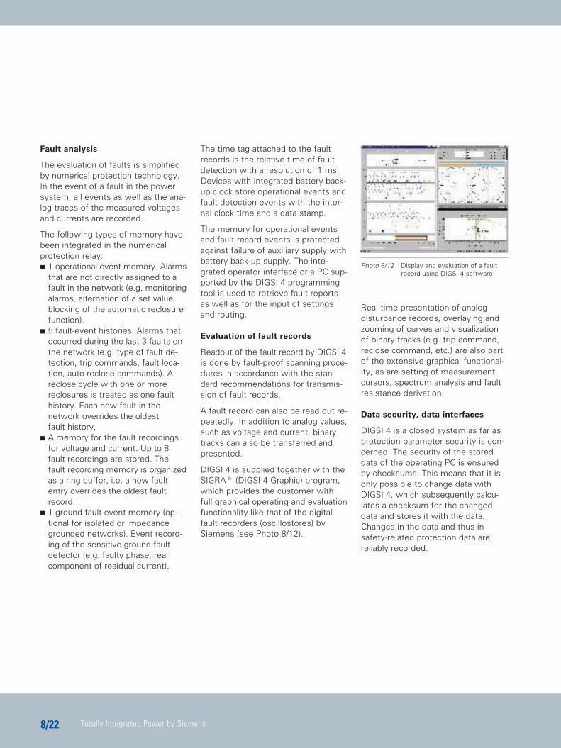
DIGSI 4 is supplied together with theSIGRA® (DIGSI 4 Graphic) program,which provides the customer withfull graphical operating and evaluationfunctionality like that of the digitalfault recorders (oscillostores) bySiemens (see Photo 8/12).
Real-time presentation of analog disturbance records, overlaying andzooming of curves and visualizationof binary tracks (e.g. trip command,reclose command, etc.) are also partof the extensive graphical functional-ity, as are setting of measurementcursors, spectrum analysis and faultresistance derivation.
Data security, data interfaces
DIGSI 4 is a closed system as far asprotection parameter security is con-cerned. The security of the storeddata of the operating PC is ensuredby checksums. This means that it isonly possible to change data withDIGSI 4, which subsequently calcu-lates a checksum for the changeddata and stores it with the data.Changes in the data and thus insafety-related protection data are reliably recorded.
Photo 8/12 Display and evaluation of a faultrecord using DIGSI 4 software
TIP_Kap_08_Engl 11.08.2005 19:44 Uhr Seite 22
Protection and Substation Control
88/23
DIGSI 4 is, however, also an opensystem. The data export functionsupports export of parameterizationand routing data in standard ASCIIformat. This permits simple access tothese data by other programs, suchas test programs, without endanger-ing the security of data within theDIGSI 4 program system.
With the import and export of faultrecords in IEEE standard formatCOMTRADE (ANSI), a high-perform-ance data interface is producedwhich supports import and export offault records into the DIGSI 4 partnerprogram SIGRA.
This enables the export of faultrecords from Siemens protectionunits to customer-specific programsvia the COMTRADE format.
Remote relay interrogation
The numerical relay range of Siemenscan also be operated from a remotelylocated PC via modem-telephoneconnection.
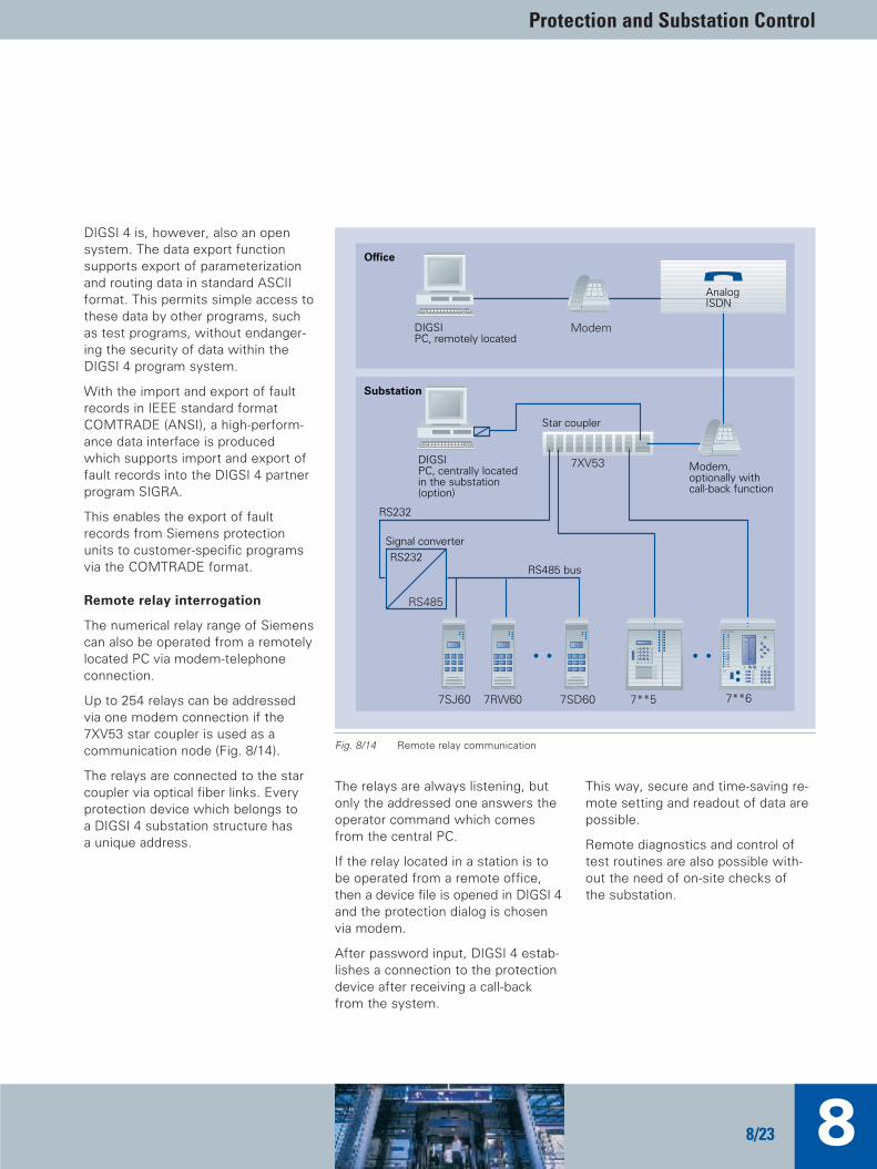
Up to 254 relays can be addressedvia one modem connection if the7XV53 star coupler is used as a communication node (Fig. 8/14).
The relays are connected to the starcoupler via optical fiber links. Everyprotection device which belongs to a DIGSI 4 substation structure hasa unique address.
The relays are always listening, butonly the addressed one answers theoperator command which comesfrom the central PC.
If the relay located in a station is tobe operated from a remote office,then a device file is opened in DIGSI 4and the protection dialog is chosenvia modem.
After password input, DIGSI 4 estab-lishes a connection to the protectiondevice after receiving a call-backfrom the system.
This way, secure and time-saving re-mote setting and readout of data arepossible.
Remote diagnostics and control oftest routines are also possible with-out the need of on-site checks of the substation.
7XV53
7**67**57SJ60 7RW60 7SD60
RS485 busRS232
RS485
DIGSIPC, centrally locatedin the substation(option)
DIGSIPC, remotely located
RS232
Modem
Office
Substation
AnalogISDN
Modem,optionally withcall-back function
Star coupler
Signal converter
Fig. 8/14 Remote relay communication
TIP_Kap_08_Engl 11.08.2005 19:44 Uhr Seite 23

Totally Integrated Power by Siemens8/24
Enclosures and terminal systems
The protection devices and the corre-sponding supplementary devices areavailable mainly in 7XP20 housings.Installation of the modules in a cabi-net without the enclosure is not permissible.
The width of the housing conformsto the 19" system with the divisions1/6, 1/3, 1/2 or 1/1 of a 19" rack. Thetermination module is located at therear of devices for panel flush mount-ing or cabinet mounting.
Screw terminals are available for devices intended for:C Panel and cabinet mountingandC Devices with a separate operator
station
The following screw-connectiontypes are to be distinguished:C Connector modules for voltage con-
nection andC Connector modules for current con-
nection
Clamping screws are slotted screwswhich shall be tightened with ascrew driver. A simple, 6 x 1 slottedscrew driver is suitable for this typeof screw heads.
Ring tongue connectors and forkedcable lugs can be used for connec-tion. To meet the insulation path re-quirements, insulated cable lugsmust be used. Or else, the crimpingzone must be insulated by other suit-able means (e.g. by covering it withshrinkdown plastic tubing).
The following requirements must be observed:
Cable lugs Bolt diameter is 4 mm; maximumouter diameter is 10 mm; for cable cross sections of 1.0 mm to 2.6 mm AWG 16 to 14 accordingly.Only use copper conductors!
Direct connection Solid conductors or litz conductorswith end sleeves; for cable cross sections of 0.5 mm to 2.6 mm AWG20 to 14 accordingly. The terminating end of the singlestrand or conductor must be pushedinto the terminal compartment insuch a way that it will be pulled intoit when the clamping screw is tight-ened. Only use copper conductors!
Wire stripping length9 mm to 10 mm for solid conductors.
Tightening torqueMax. 1.8 Nm.
The heavy-duty current plug connec-tors provide automatic short-circuit-ing of the current transformer circuitswhen the modules are withdrawn.Whenever secondary circuits of current transformers are concerned,
special precautions are to be taken.In the housing version for surfacemounting, the terminals are wired upon terminal strips on the top and bot-tom of the device. For this purposetwo-tier terminal blocks are used toattain the required number of terminals.
According to IEC 60529, the degreeof protection is indicated by the identi-fying IP, followed by a number for thedegree of protection. The first digitindicates the protection against acci-dental contact and ingress of solidforeign bodies, the second digit indi-cates the protection against water.7XP20 housings are protectedagainst ingress of dangerous parts,dust and dripping water (IP 51).
For mounting of devices intoswitchgear cabinets, 8MC switchgearcabinets are recommended.
The standard cabinet has the following dimensions:
2,200 mm x 900 mm x 600 mm (H x W x D). These cabinets are pro-vided with a 44 U high mounting rack(standard height unit U = 44.45 mm).It can swivel as much as 180° in aswing frame. The rack provides for amounting width of 19", allowing, forexample, 2 devices with a width of1/2 x 19" to be mounted. The devicesin the 7XP20 housing are secured torails by screws. Module racks are notrequired.
TIP_Kap_08_Engl 11.08.2005 19:44 Uhr Seite 24

Protection and Substation Control
88/25
8.3 Relay Selection Guide
Table 8/6 Relay selection guide
TypeProtective functions
ANSI No.1) Description
14 Locked rotor – – – – – – – V V V V – – – – –
21 Distance protection, phase C – – – – – – – – – – – – – – –
21N Distance protection, ground C – – – – – – – – – – – – – – –
21FL Fault locator C – – – – – – – V V V – – – – –
24 Overfluxing ( U/f) – – – – – – – – – – – – V V – –
25 Synchro-check V – – – – – – – – – V – – – – –
27 Undervoltage V – – – – – – – V V V – – – – –
27/34 U/f protection – – – – – – – – – – – – – – – –voltage/frequency protection
32 Directional power – – – – – – – – – – V – – – – –
32F Forward power – – – – – – – – – – V – – – – –
32R Reverse power – – – – – – – – – – V – – – – –
37 Undercurrent or underpower – – – – – – V C C C C – – – – –
40 Protection against under-excitation – – – – – – – – – – – – – – – –
46 Load unbalance protection – – – – – – C C C C C V – V – –
47 Phase sequence monitoring C – – – – – – – C C C – – – – –
48 Start-up current-time monitoring – – – – – – V V V V V – – – – –
49 Thermal overload V – C – – C C C C C C C C C – –
49R Rotor overload protection – – – – – C C C C C C – – – – –
49S Stator overload protection – – – – – C C C C C C – – – – –
50 Instantaneous overcurrent C C C C C C C C C C C – C C C –
50N Instantaneous ground fault overcurrent C – C – – C C C C C C – C C C –
50BF Breaker failure V – V – – – C C C C C V V V V –
51GN Stator ground-fault overcurrent – – – – – – – – – – – – – – – –
51 Overcurrent with time delay C C C C C C C C C C C – C C C –
7SA
6D
ista
nce
pro
tect
ion
7SD
600
7SD
610
7SJ4
5O
verc
urr
en
t
7SJ4
6
7SJ6
00
7SJ6
02
7SJ6
1
7SJ6
2
7SJ6
3
7SJ6
4
7VH
60D
iffe
ren
tial
7UT
612
7UT
613
7UT
63
7SS
60
Pil
ot
wir
e d
iffe
ren
tial
Op
tica
l w
ave
gu
ide
cu
rre
nt
com
par
iso
n
C Standard function V Option
1) ANSI (American National Standards Institute) /IEEE (Institute of Electrical and Electronic Engineers)C 37.2: IEEE Standard Electrical Power System Device Function Numbers
TIP_Kap_08_Engl 11.08.2005 19:44 Uhr Seite 25
Totally Integrated Power by Siemens8/26
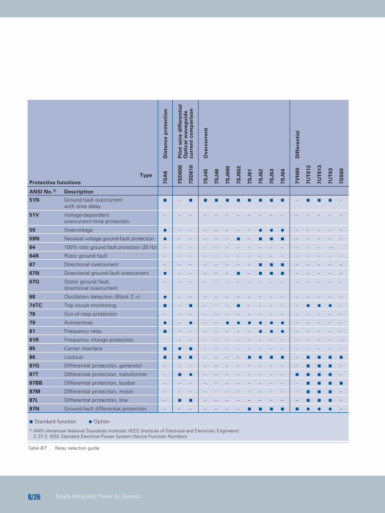
Table 8/7 Relay selection guide
TypeProtective functions
ANSI No.1) Description
51N Ground-fault overcurrent C – C C C C C C C C C – C C C –with time delay
51V Voltage-dependent – – – – – – – – – – – – – – – –overcurrent-time protection
59 Overvoltage V – – – – – – – V V V – – – – –
59N Residual voltage ground-fault protection V – – – – – C – C C C – – – – –
64 100% rotor ground fault protection (20 Hz) – – – – – – – – – – – – – – ––
64R Rotor ground fault – – – – – – – – – – – – – – – –
67 Directional overcurrent – – – – – – – – C C C – – – – –
67N Directional ground-fault overcurrent V – – – – – C – C C C – – – – –
67G Stator ground fault, – – – – – – – – – – – – – – – –directional overcurrent
68 Oscillation detection (Block Z <) V – – – – – – – – – – – – – – –
74TC Trip circuit monitoring C – C – – – C – – – – – V V V –
78 Out-of-step protection – – – – – – – – – – – – – – – –
79 Autoreclose V – V – – V V V V V V – – – – –
81 Frequency relay C – – – – – – – V V V – – – – –
81R Frequency change protection – – – – – – – – – – – – – – ––
85 Carrier interface C V C – – – – – – – – – – – – –
86 Lockout C C C – – – – C C C C – C C C C
87G Differential protection, generator – – – – – – – – – – – – C C C –
87T Differential protection, transformer – C V – – – – – – – – C C C C –
87BB Differential protection, busbar – – – – – – – – – – – – C C C C
87M Differential protection, motor – – – – – – – – – – – – C C C –
87L Differential protection, line – C C – – – – – – – – – C C C –
87N Ground-fault differential protection – – – – – – – C C C C C V V V –
7SA
6D
ista
nce
pro
tect
ion
7SD
600
7SD
610
7SJ4
5O
verc
urr
en
t
7SJ4
6
7SJ6
00
7SJ6
02
7SJ6
1
7SJ6
2
7SJ6
3
7SJ6
4
7VH
60D
iffe
ren
tial
7UT
612
7UT
613
7UT
63
7SS
60
Pil
ot
wir
e d
iffe
ren
tial
Op
tica
l w
ave
gu
ide
cu
rre
nt
com
par
iso
n
C Standard function V Option
1) ANSI (American National Standards Institute) /IEEE (Institute of Electrical and Electronic Engineers)C 37.2: IEEE Standard Electrical Power System Device Function Numbers
TIP_Kap_08_Engl 11.08.2005 19:44 Uhr Seite 26
Protection and Substation Control
88/27
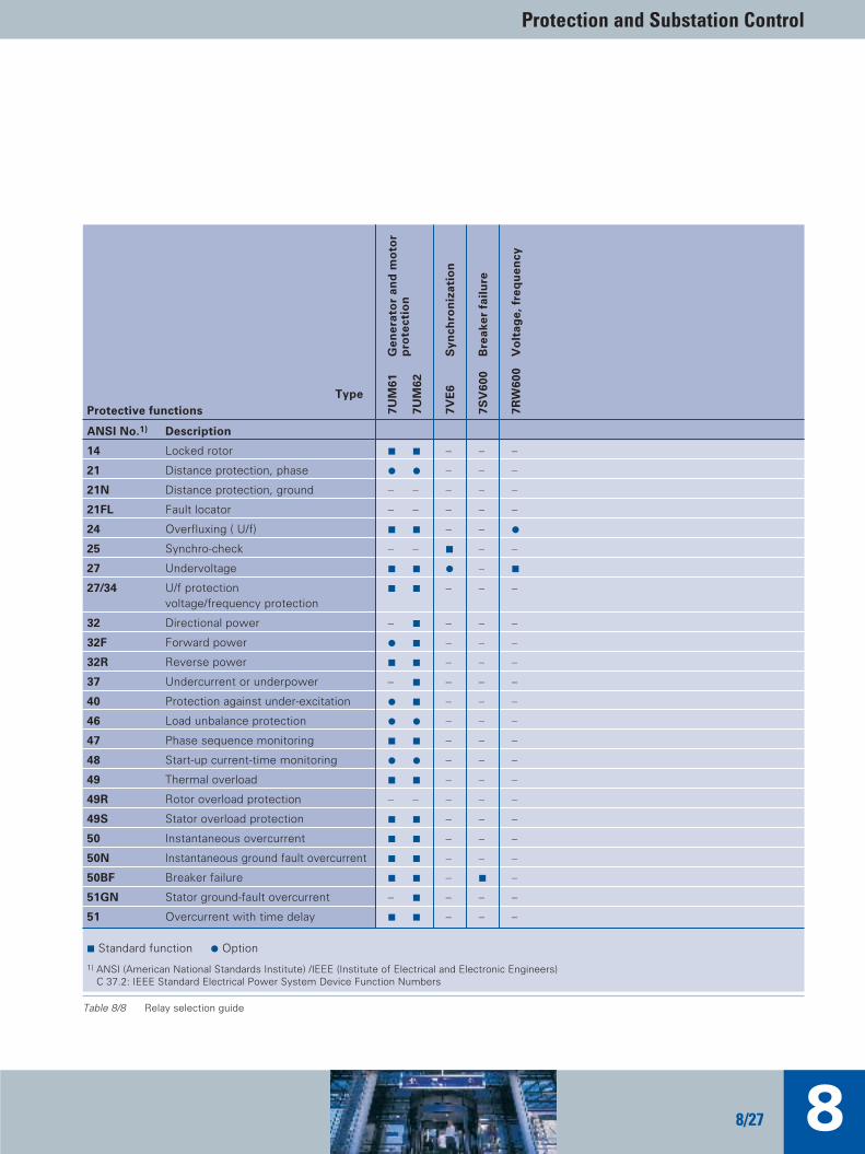
Table 8/8 Relay selection guide
TypeProtective functions
ANSI No.1) Description
14 Locked rotor C C – – –
21 Distance protection, phase V V – – –
21N Distance protection, ground – – – – –
21FL Fault locator – – – – –
24 Overfluxing ( U/f) C C – – V
25 Synchro-check – – C – –
27 Undervoltage C C V – C
27/34 U/f protection C C – – –voltage/frequency protection
32 Directional power – C – – –
32F Forward power V C – – –
32R Reverse power C C – – –
37 Undercurrent or underpower – C – – –
40 Protection against under-excitation V C – – –
46 Load unbalance protection V V – – –
47 Phase sequence monitoring C C – – –
48 Start-up current-time monitoring V V – – –
49 Thermal overload C C – – –
49R Rotor overload protection – – – – –
49S Stator overload protection C C – – –
50 Instantaneous overcurrent C C – – –
50N Instantaneous ground fault overcurrent C C – – –
50BF Breaker failure C C – C –
51GN Stator ground-fault overcurrent – C – – –
51 Overcurrent with time delay C C – – –
7UM
61G
en
era
tor
and
mo
tor
7UM
62p
rote
ctio
n
7VE
6S
ynch
ron
izat
ion
7SV
600
Bre
ake
r fa
ilu
re
7RW
600
Vo
ltag
e,
fre
qu
en
cy
C Standard function V Option
1) ANSI (American National Standards Institute) /IEEE (Institute of Electrical and Electronic Engineers)C 37.2: IEEE Standard Electrical Power System Device Function Numbers
TIP_Kap_08_Engl 11.08.2005 19:44 Uhr Seite 27
Totally Integrated Power by Siemens8/28
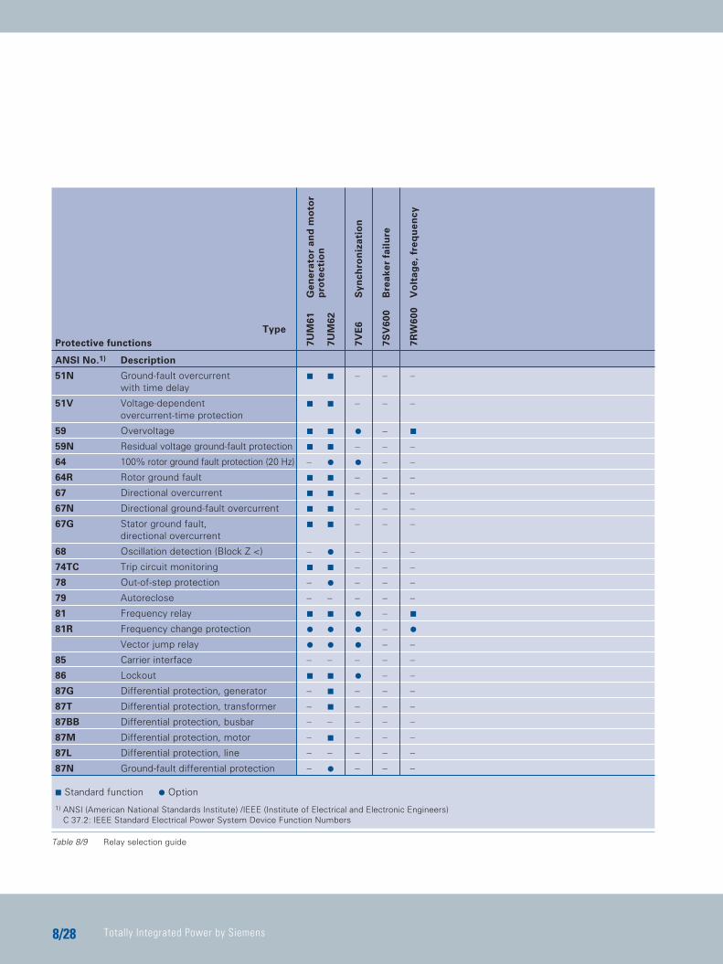
Table 8/9 Relay selection guide
TypeProtective functions
ANSI No.1) Description
51N Ground-fault overcurrent C C – – –with time delay
51V Voltage-dependent C C – – –overcurrent-time protection
59 Overvoltage C C V – C
59N Residual voltage ground-fault protection C C – – –
64 100% rotor ground fault protection (20 Hz) – V V – –
64R Rotor ground fault C C – – –
67 Directional overcurrent C C – – –
67N Directional ground-fault overcurrent C C – – –
67G Stator ground fault, C C – – –directional overcurrent
68 Oscillation detection (Block Z <) – V – – –
74TC Trip circuit monitoring C C – – –
78 Out-of-step protection – V – – –
79 Autoreclose – – – – –
81 Frequency relay C C V – C
81R Frequency change protection V V V – V
Vector jump relay V V V – –
85 Carrier interface – – – – –
86 Lockout C C V – –
87G Differential protection, generator – C – – –
87T Differential protection, transformer – C – – –
87BB Differential protection, busbar – – – – –
87M Differential protection, motor – C – – –
87L Differential protection, line – – – – –
87N Ground-fault differential protection – V – – –
7UM
61G
en
era
tor
and
mo
tor
7UM
62p
rote
ctio
n
7VE
6S
ynch
ron
izat
ion
7SV
600
Bre
ake
r fa
ilu
re
7RW
600
Vo
ltag
e,
fre
qu
en
cy
C Standard function V Option
1) ANSI (American National Standards Institute) /IEEE (Institute of Electrical and Electronic Engineers)C 37.2: IEEE Standard Electrical Power System Device Function Numbers
TIP_Kap_08_Engl 11.08.2005 19:44 Uhr Seite 28
Protection and Substation Control
88/29
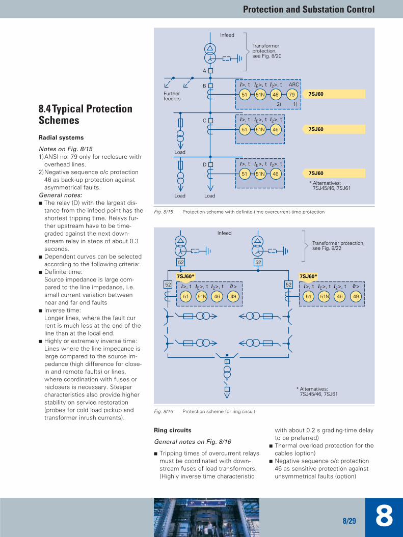
8.4 Typical ProtectionSchemesRadial systems
Notes on Fig. 8/151)ANSI no. 79 only for reclosure with
overhead lines.2)Negative sequence o/c protection
46 as back-up protection againstasymmetrical faults.
General notes:C The relay (D) with the largest dis-
tance from the infeed point has theshortest tripping time. Relays fur-ther upstream have to be time-graded against the next down-stream relay in steps of about 0.3seconds.
C Dependent curves can be selectedaccording to the following criteria:
C Definite time: Source impedance is large com-pared to the line impedance, i.e. small current variation between near and far end faults
C Inverse time:Longer lines, where the fault current is much less at the end of the line than at the local end.
C Highly or extremely inverse time:Lines where the line impedance islarge compared to the source im-pedance (high difference for close-in and remote faults) or lines,where coordination with fuses orreclosers is necessary. Steepercharacteristics also provide higherstability on service restoration(probes for cold load pickup andtransformer inrush currents).
Ring circuits
General notes on Fig. 8/16
C Tripping times of overcurrent relaysmust be coordinated with down-stream fuses of load transformers.(Highly inverse time characteristic
with about 0.2 s grading-time delayto be preferred)
C Thermal overload protection for thecables (option)
C Negative sequence o/c protection46 as sensitive protection againstunsymmetrical faults (option)
51N51 46 79
51N51 46
51N51 46
Infeed
Furtherfeeders
I>, t IE>, t I2>, t ARC
2) 1)
I>, t IE>, t I2>, t
A
B
C
Load
Load Load
D I>, t IE>, t I2>, t
7SJ60
7SJ60
7SJ60
Transformerprotection,see Fig. 8/20
* Alternatives: 7SJ45/46, 7SJ61
Fig. 8/15 Protection scheme with definite-time overcurrent-time protection
51N51 46 49
I>, t IE>, t I2>, t52
5252
51N51 46 49
I>, t IE>, t I2>, t ϑ>52ϑ>
* Alternatives: 7SJ45/46, 7SJ61
Infeed
7SJ60*
Transformer protection,see Fig. 8/22
7SJ60*
Fig. 8/16 Protection scheme for ring circuit
TIP_Kap_08_Engl 11.08.2005 19:44 Uhr Seite 29

Totally Integrated Power by Siemens8/30
Distribution feeder with reclosers
General notes on Fig. 8/17: C The feeder relay operating charac-
teristics, delay times and autoreclo-sure cycles must be carefully coor-dinated with downstream reclosers,switch disconnectors and fuses.The instantaneous zone 50/50N isnormally set to reach out to the firstmain feeder sectionalizing point. Ithas to ensure fast clearing of close-in faults and prevent blowing offuses in this area (“fuse saving”).Fast autoreclosure is initiated in thiscase. Further time-delayed trippingand reclosure steps (normally 2 or 3)have to be graded against the recloser.
C The o/c relay should automaticallyswitch over to less sensitive charac-teristics after longer load interrup-tion times to enable overriding ofsubsequent cold load pickup andtransformer inrush currents.
Parallel lines
General notes on Fig. 8/18: C This configuration is preferably
used for the uninterrupted supplyof important consumers withoutsignificant backfeed.
C The directional o/c protection 67/67N trips instantaneously for
faults on the protected line. This allows the saving of one time-grading interval for the o/c relays at the infeed.
C The o/c relay functions 51/51Nhave each to be time-gradedagainst the relays located upstream.
52
50/51
50N/51N 46
79
52
7SJ607SJ61
Infeed
I>>,I>, t
IE>>,IE>, t
I2>, t
Autoreclose
Recloser
Sectionalizers
Fuses
Furtherfeeders
52
51N51 49 46 7SJ60
7SJ6267N67 51 51N
52
52
52
52
52
52
52
52
Infeed
Protectionsame asline or cable 1
I>, t IE>, t I2>, tϑ>
Load
OH line orcable 1
OH line orcable 2
Load
Fig. 8/17 Protection scheme for distribution feeder
Fig. 8/18 Protection concept for parallel lines
TIP_Kap_08_Engl 11.08.2005 19:44 Uhr Seite 30
Protection and Substation Control
88/31
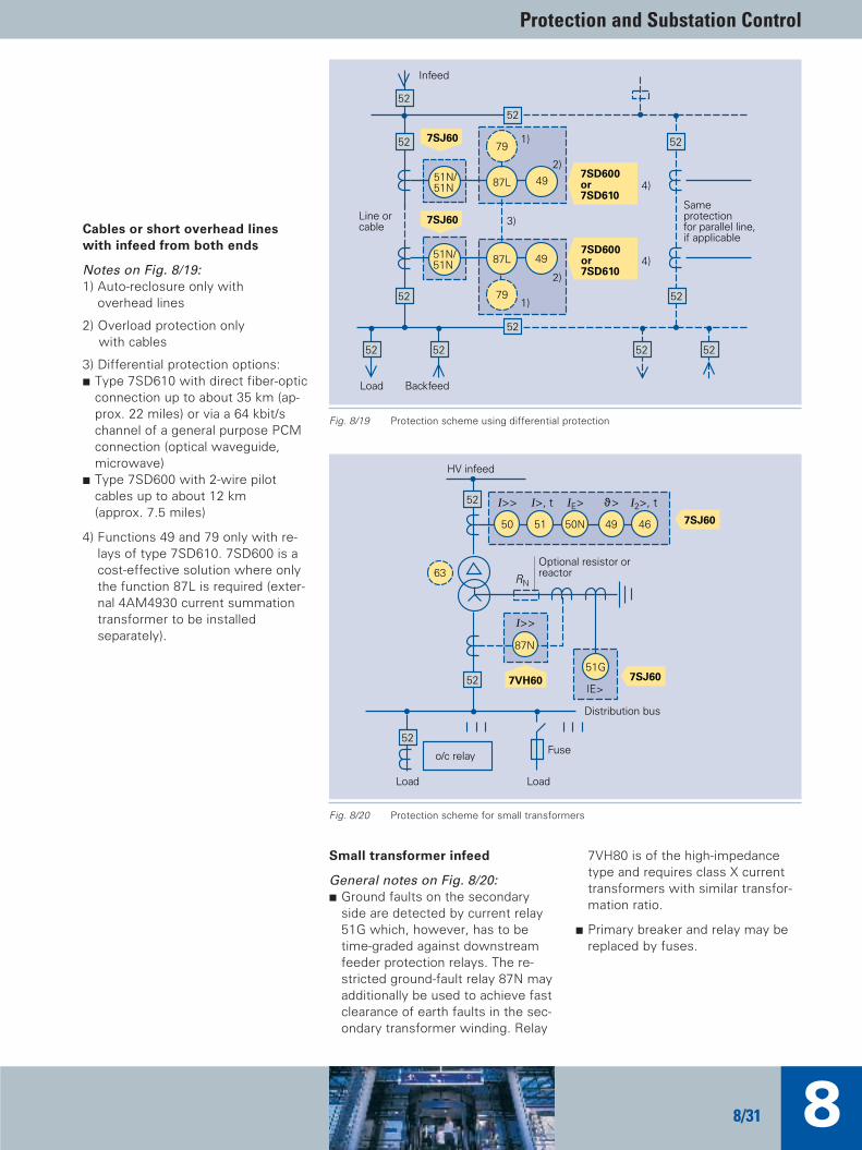
Cables or short overhead lineswith infeed from both ends
Notes on Fig. 8/19: 1) Auto-reclosure only with
overhead lines
2) Overload protection only with cables
3) Differential protection options: C Type 7SD610 with direct fiber-optic
connection up to about 35 km (ap-prox. 22 miles) or via a 64 kbit/schannel of a general purpose PCMconnection (optical waveguide, microwave)
C Type 7SD600 with 2-wire pilot cables up to about 12 km (approx. 7.5 miles)
4) Functions 49 and 79 only with re-lays of type 7SD610. 7SD600 is acost-effective solution where onlythe function 87L is required (exter-nal 4AM4930 current summationtransformer to be installed separately).
Small transformer infeed
General notes on Fig. 8/20: C Ground faults on the secondary
side are detected by current relay51G which, however, has to betime-graded against downstreamfeeder protection relays. The re-stricted ground-fault relay 87N mayadditionally be used to achieve fastclearance of earth faults in the sec-ondary transformer winding. Relay
7VH80 is of the high-impedancetype and requires class X currenttransformers with similar transfor-mation ratio.
C Primary breaker and relay may bereplaced by fuses.
52
52
52
51N/51N 87L
79
49
1)
2)
52
51N/51N 87L
79
49
1)
2)
3)
52
52
52
52 52 52 52
4)
4)
7SD600or7SD610
7SD600or7SD610
Load
Infeed
Sameprotectionfor parallel line,if applicable
Line orcable
Backfeed
7SJ60
7SJ60
5150 50N 49
7SJ60
52
52
46
63
87N
51G
7SJ60
RN
52
HV infeed
I>> I>, t IE> ϑ>
Load
Optional resistor orreactor
I2>, t
I>>
IE>7VH60
o/c relay
Distribution bus
Fuse
Load
Fig. 8/19 Protection scheme using differential protection
Fig. 8/20 Protection scheme for small transformers
TIP_Kap_08_Engl 11.08.2005 19:44 Uhr Seite 31
Totally Integrated Power by Siemens8/32
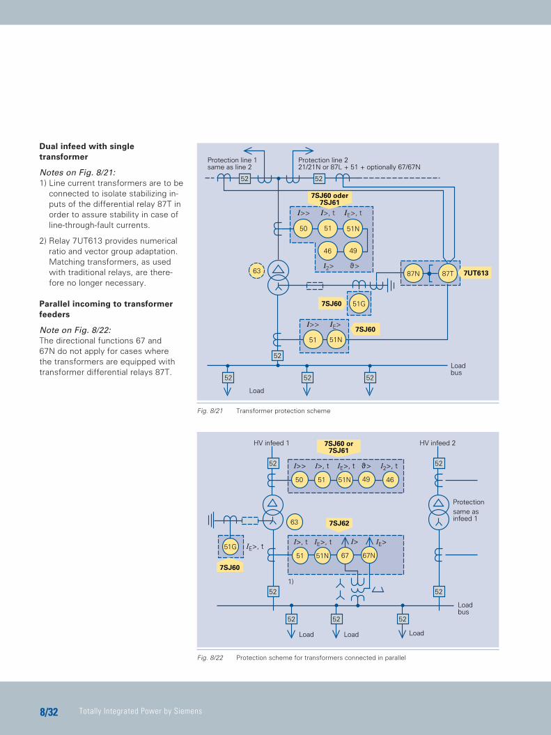
Dual infeed with single transformer
Notes on Fig. 8/21: 1) Line current transformers are to be
connected to isolate stabilizing in-puts of the differential relay 87T inorder to assure stability in case ofline-through-fault currents.
2) Relay 7UT613 provides numericalratio and vector group adaptation.Matching transformers, as usedwith traditional relays, are there-fore no longer necessary.
Parallel incoming to transformerfeeders
Note on Fig. 8/22: The directional functions 67 and 67N do not apply for cases where the transformers are equipped with transformer differential relays 87T.
52 52
46
51 51N50
49
63
7SJ60
7SJ60
52
52 52 52
7UT61387T87N
Protection line 1same as line 2
Load
I>> IE>
Protection line 221/21N or 87L + 51 + optionally 67/67N
I>> I>, t IE>, t
ϑ>I2>
7SJ60 oder7SJ61
Loadbus
51G
51N51
5150 51N 49 46
52
52
51G
52
52
52 52
63
51N51
52
67 67N
I>, t IE>, t IE>
7SJ62
I>> I>, t IE>, t ϑ> I2>, t
Load
HV infeed 1
7SJ60
Load
HV infeed 27SJ60 or7SJ61
Protectionsame asinfeed 1
I>
1)
Load
Loadbus
IE>, t
Fig. 8/22 Protection scheme for transformers connected in parallel
Fig. 8/21 Transformer protection scheme
TIP_Kap_08_Engl 11.08.2005 19:44 Uhr Seite 32

Protection and Substation Control
88/33
Small and medium-sized motors < 1 MW
With effective or low-resistancegrounded infeed (IIE ≥ IIN Motor)
General note on Fig. 8/23: Applicable to low-voltage motors andhigh-voltage motors with low-resist-ance grounded infeed (IE ≥ IN Motor).
With high-resistance grounded in-feed (IIE ≤ IIN Motor)
Notes on Fig. 8/24: 1) 1) Window-type zero-sequence
current transformer.
2) Sensitive directional earth-faultprotection 67N only applicablewith infeed from isolated or Peter-son-coil-grounded network. (For di-mensioning of the sensitive direc-tional ground-fault protection, alsosee application circuit No. 24)
3) Relay type 7SJ602 may be usedfor power systems with isolatedneutral or compensated neutral
Large HV motors > 1 MW
Notes on Fig. 8/25:1) Window-type zero-sequence
current transformer.
2) Sensitive directional ground-faultprotection 67N only applicablewith infeed from isolated or Peterson-coil-grounded network.
3) This function is only needed formotors where the start-up time islonger than the safe stall time tE.According to IEC 79-7,tE is thetime needed to heat up AC wind-ings, when carrying the startingcurrent IA, from the temperaturereached in rated service and atmaximum ambient temperature to the limiting temperature.
Fig. 8/23 Protection scheme for small motors
Fig. 8/25 Protection scheme for large motors
49CR
52
4951N50 7SJ60
M
I>> Lockedrotor
IE> ϑ>
46
I2>
52
507SJ62or7SJ602
51G 67N
M
I>>
IE>
ϑ> I2>
4649
I<
37
2)7XR961)60/1A
3)
52
50
7UM62
51N 67N
49T
Speedswitch M
87M
37
4)
I>>
IE>
ϑ>I2>
4649
U<
27
2)7XR961)60/1A
Monitoring ofthe start-upstage
I<optionally
Option:thermistor
3)
3)
5)
Fig. 8/24 Protection scheme for medium-sized motors
TIP_Kap_08_Engl 11.08.2005 19:44 Uhr Seite 33
Totally Integrated Power by Siemens8/34
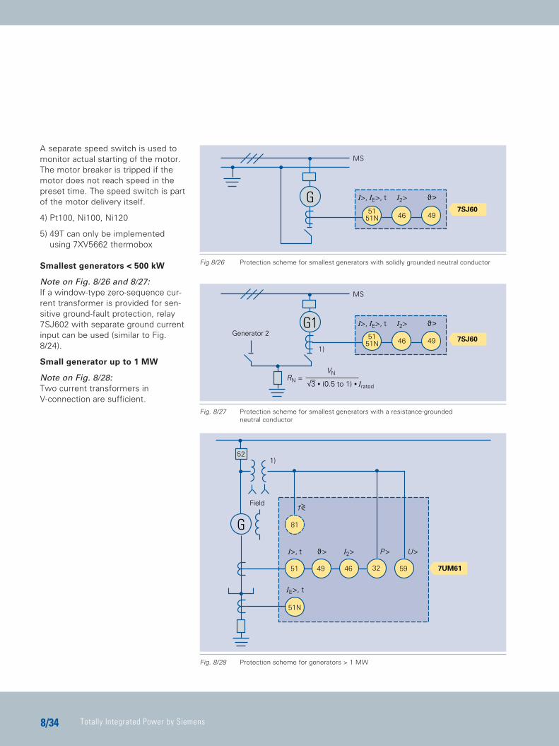
A separate speed switch is used tomonitor actual starting of the motor.The motor breaker is tripped if themotor does not reach speed in thepreset time. The speed switch is partof the motor delivery itself.
4) Pt100, Ni100, Ni120
5) 49T can only be implemented using 7XV5662 thermobox
Smallest generators < 500 kW
Note on Fig. 8/26 and 8/27: If a window-type zero-sequence cur-rent transformer is provided for sen-sitive ground-fault protection, relay7SJ602 with separate ground currentinput can be used (similar to Fig.8/24).
Small generator up to 1 MW
Note on Fig. 8/28: Two current transformers in V-connection are sufficient.
Fig 8/26 Protection scheme for smallest generators with solidly grounded neutral conductor
Fig. 8/27 Protection scheme for smallest generators with a resistance-grounded neutral conductor
Fig. 8/28 Protection scheme for generators > 1 MW
7SJ60G
46 4951
51N
I>, IE>, t
MS
I2> ϑ>
G146 49
5151N
7SJ60
RN =VN
√3 • (0.5 to 1) • Irated
1)
I>, IE>, t I2> ϑ>
MS
Generator 2
52
7UM61
G
51
51N
81
P>I>, t
IE>, t
ϑ>
49 32
U>
59
1)
I2>
46
f><Field
TIP_Kap_08_Engl 11.08.2005 19:44 Uhr Seite 34
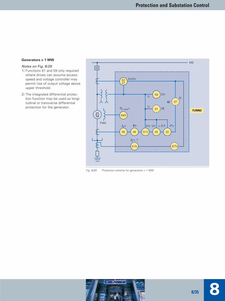
Protection and Substation Control
88/35
Generators > 1 MW
Notes on Fig. 8/29: 1) Functions 81 and 59 only required
where drives can assume excessspeed and voltage controller maypermit rise of output voltage aboveupper threshold.
2) The integrated differential protec-tion function may be used as longi-tudinal or transverse differentialprotection for the generator.
52
G
51N
64R
5027
59
87
81
46 49 51V 40 32
7UM62
87N
MS
RE field<
I>t, U<I2> L.O.F.ϑ>
1) 2)U<
-P>
f><
IE>, t
Field
∆I
1)
I>/U<
Fig. 8/29 Protection scheme for generators > 1 MW
TIP_Kap_08_Engl 11.08.2005 19:45 Uhr Seite 35
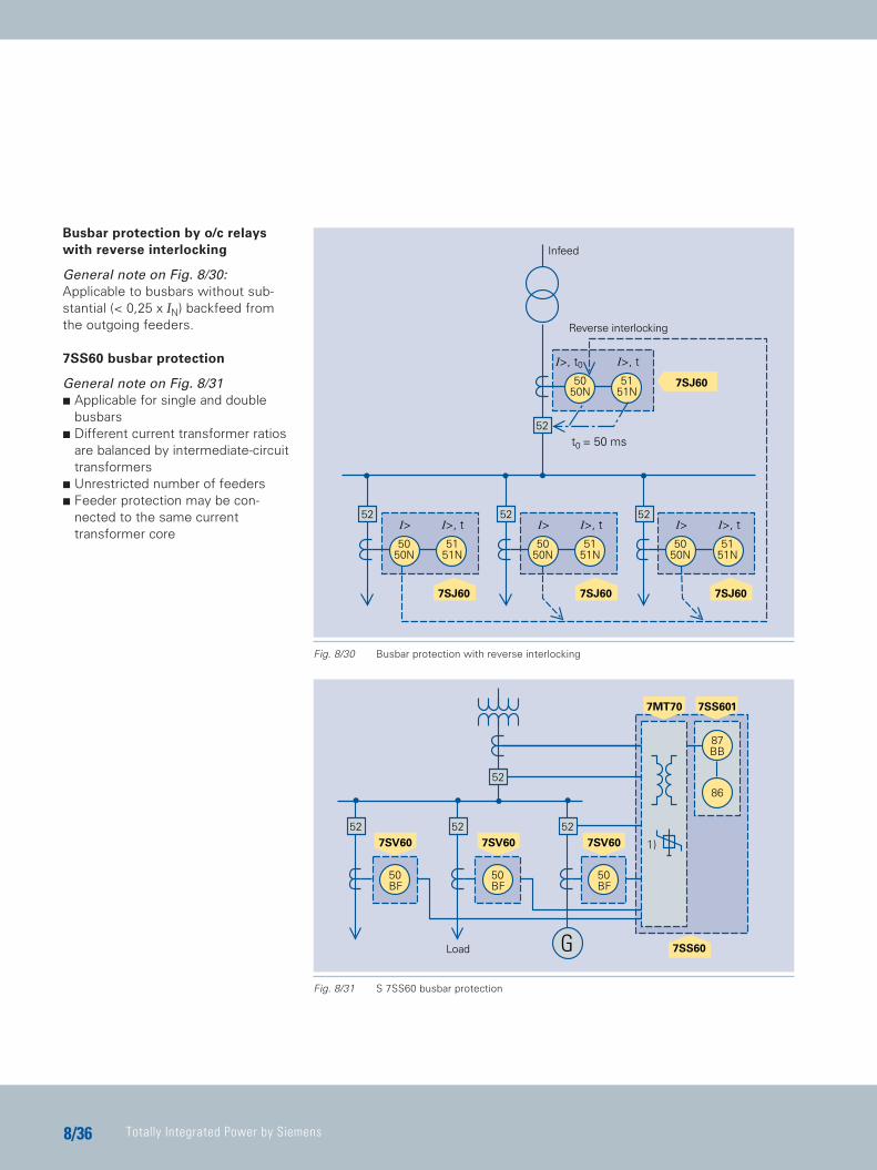
Totally Integrated Power by Siemens8/36
Busbar protection by o/c relayswith reverse interlocking
General note on Fig. 8/30:Applicable to busbars without sub-stantial (< 0,25 x IN) backfeed fromthe outgoing feeders.
7SS60 busbar protection
General note on Fig. 8/31C Applicable for single and double
busbars C Different current transformer ratios
are balanced by intermediate-circuittransformers
C Unrestricted number of feeders C Feeder protection may be con-
nected to the same current transformer core
Fig. 8/30 Busbar protection with reverse interlocking
52
7SS601
52
GLoad
52
52
87BB
86
1)
50BF
50BF
50BF
7MT70
7SV607SV607SV60
7SS60
52
52
5050N
5151N
52
5050N
5151N
5050N
5151N
52
5050N
5151N
7SJ60
7SJ60
7SJ60 7SJ60
t0 = 50 ms
I> I>, t I> I>, t
I>, t0 I>, t
I> I>, t
Infeed
Reverse interlocking
Fig. 8/31 S 7SS60 busbar protection
TIP_Kap_08_Engl 11.08.2005 19:45 Uhr Seite 36
Protection and Substation Control
88/37
TIP_Kap_08_Engl 11.08.2005 19:45 Uhr Seite 37

TIP_Kap_09_Engl 11.08.2005 19:35 Uhr Seite B