Prosistel Manual rev 2001-12A
25
PROSISTEL Antenna Rotator User’s manual Array Solutions-RME Filters, Inc. 350 Gloria Rd. Sunnyvale, Texas ,USA 75182 Phone: 972-203-2008 Fax: 972-203-8811 E-mail: [email protected] Web Site: www.arraysolutions.com
Transcript of Prosistel Manual rev 2001-12A

PROSISTEL
Antenna Rotator
User’s manual
Array Solutions-RME Filters, Inc.350 Gloria Rd.
Sunnyvale, Texas ,USA75182
Phone: 972-203-2008 Fax: 972-203-8811
E-mail: [email protected]
Web Site: www.arraysolutions.com

2
Warning
This manual must be read carefully before proceeding withwiring and installation
Warranty1) The rotator with the control box, hereafter called “rotator” or “product”, is warranted for 2 yearsfrom date of purchase.
2) The warranty covers replacement or repair of the defective component.
3) This warranty does not apply to product which have been subjected to misuse, negligence,incorrect wiring performed by the user, improper installation or non-compliance to instructionsfurnished by Array Solutions Inc., damage to product which has been repaired or altered withoutauthorization or to injury resulting from careless maintenance. The warranty does not coverdamage due to transportation.
4) The warranty does not cover costs and risk relating to the shipping of the rotator for repair.
5) Array Solutions, Inc. is not responsible for personal injury or property damage resulting fromimproper or careless use of the rotator.
6) This warranty is not cover damage to people or things due to misuse, improper or carelessinstallation, or misunderstanding of instructions furnished by Array Solutions, Inc.
7) Array Solutions, Inc. reserves the right to implement improvements and changes without priornotification.
Model: PST ________
S/N: _____________
Date of purchase: ______________

3
Introduction
This manual contains installation, use and maintenance information for the modelsPST 51, 61, and 71 antenna rotators.
Table of Contents
Section 1: Description
Section 2: Installation and Wiring
Section 3: Principles of Operation
Section 4: Specifications
Section 5: Special Functions
Section 6: Mounting Hole Pattern
Section 7: Tower Mounting Information
Section 8: Schematic - Model A Control Box
Appendix 1: Model B Control Box
Appendix 2: Model C Control Box
Appendix 3: Connector Information
4
Section 1Description
1.1 GeneralThis manual provides information for installation on a mounting plate inside a tower or a rotatorcage with a thrust bearing. The rotator consists of a motor unit and a control box.
1.2 Unpacking and InspectionBe sure to check the rotator and control box for damage, especially if there is damage to theshipping carton.
1.3 Control BoxThe following functions are located on the front panel of the control box (Fig. 1): power switch,rotation direction switch and the digital display that indicates the antenna position in degrees. (Seeappendix 1 for Model B control box and appendix 2 for Model C control box)
BEARING
CWCCW
Power
PRO.SIS.TEL.
Display
Fig. 1
On the rear of the control box the following is located (Fig. 2): AC line power input socket, fuse holder,rotator control cable socket and DB9S connector for remote control (i.e. computer interface orfootswitch ).

5
Remote controlFuse 1A
A/C power
socket
Socket forrotor controlcable
Fig. 21.4 The Rotator
The motor is located on the side of a double worm geared drive in vertical position and coveredwith a plate to prevent snow and ice from entering the motor fan. The main gear box is terminatedon a flat plate and provides the rotation motion to the antenna via mast clamp. A standard mastclamp is provided with the rotator. (There are several optional mast clamp assemblies available.Contact Array Solutions for more information) A weather poof housing is located on the side of themotor. A six terminal connection block is located inside this housing. Connections are provide formotor power, bearing indication potentiometer, and ground. The potentiometer is located in themain gear box.
Flexible mast clamp
48 Vac motor
Rotator Mounting Plate
Standard mast clamp

6
MotorRotator body
Top View
Mast clampplate
1.4.1 AccessoriesRotator is supplied with following accessories: AC power cable, plug for rotator control cable,standard mast clamp, stainless steel hardware and users manual.
Section 2Installation and Wiring
2.1 Control Cable Preparation & ConnectionBefore installing rotator inside tower, you need to prepare the rotator control cable and test rotatorfor proper operation on the ground. The rotator requires 7 wires. Three wires for motor power, 3wires for the position potentiometer and 1 wire for ground. The required wire size is a function ofcable length. Improper wire size will result in reduced voltage to the motor and limit torque.Minimum wire size based on maximum cable length is indicated in the chart below. The threeheavier wires are used to power the motor. You can parallel conductors (if the cable has morethan 7 wires) to achieve the minimum conductor size.
Model PST 51 PST 61 PST 71150 feet Three #18 and four #22 Three #18 and four #22 Three #16 and four #22150 to 300 feet Three #16 and four #22 Three #16 and four #22 Three #14 and four #22
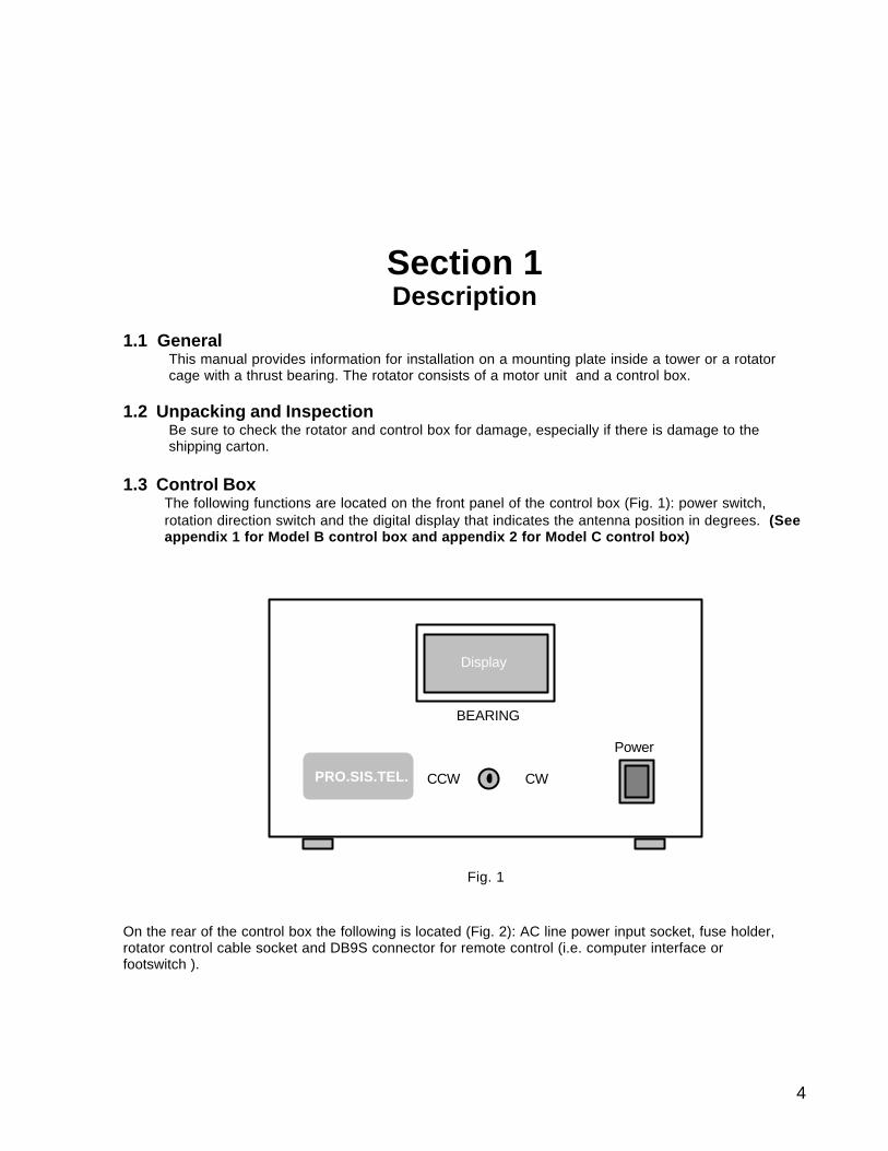
An 8 pin connector (only 7 of the 8 pins are used) is used to connect the rotator cable to the control box.The cable wires must be soldered to the connector pins. Connections to the motor terminal block madevia ring terminals. Make sure that you use a proper crimping tool.
Warning: The control cable connector pins snap into the connector bodyand cannot be removed, once inserted. Make sure that you have a good solderconnection to the pin and that the proper wire is inserted into the correct pinlocation. The pin numbers are stamped on the cable end of the connector body.Do not operate the rotator until you have ALL 7 connections made between thecontrol box and rotator.
7
8 mm PinControl Cable
Connector Cover
Connector Body
Pin Numbers Stamped on this Surface
1
2
3
4
5
Control cable connector body
!! viewed from cable end !!
= F1
= F2
7= F3 = P
= - 12 (-)
= + 12 (+)6= Not Used
F1
F2
F3
+12 Vdc
-12 Vdc
P
View looking at the terminal block located on the motor
8= ground
Ring Terminal
Ground screw
Control Box Motor Function Wire ColorPin #1 P Pot WiperPin #2 F2 Motor CCWPin #3 -12 -12 Vdc to potPin #4 +12 +12 Vdc to potPin #5 F1 Motor CommonPin #6 (No Connection) No Connection No ConnectionPin #7 F3 Motor CWPin #8 Ground Ground
Warning: Improper wiring can result in damage of the motor and/orcontrol box. Double check your wiring and connections!!!!
2.2 InspectionCarefully check the rotator and control box cable connections before turning on the power for thefirst time.

8
2.3 Pre-installation checkControl box is preset for 117 VAC (USA). Contact Array Solutions if you require information forproduct use with 220 VAC. (See Appendix 1 if you have a Model B control box and appendix2 for model C control box) Connect the power cable to a suitable 117 VAC outlet and switchpower on. The display will show 000°. Switch power off and insert the control cable connector intothe socket on the rear of the control box. Switch power on and if all connections are correct,display will show about 000°. If the bearing display indicates a value much different, switch thepower off and check the control cable connections. Push the direction lever in CW direction androtator will turn to the right or clockwise rotation. The display value will follow the rotator rotation.Continue turning CW until the rotator hits the electronic clockwise stop. The motor rotation shouldstop and the display will show about 400°. You should be able to notice a difference in the soundof the motor when it hits the electronic stop. Switch direction lever to CCW rotation and rotator willturn back to the left, counter clockwise rotation. Continue turning in the CCW direction until you hitthe CCW electronic stop. The display should indicate about -40°. Proceed back it the CWdirection until the display reads 000° and shut the power off.
2.4 TroubleshootingA) Motor does not respond1) Check the motor and connector wiring.2) Check the fuse. If it has failed, replace it and turn the power on. If it fails again, remove thecontrol cable connector from the back of the control box and turn the power. If the control boxdisplay is lit, the problem is probably in the cable wiring.
B) Motor turns in the opposite direction1) Check the connections (F1, F2 and F3) on the motor terminal board.2) Check the control cable pin wiring and pin location in the connector housing.
C) When motor was running in reverse of the desired direction (See B above), the electronicstop was activated and now the motor will not respond1) Switch off the control box and disconnect terminal P on the motor terminal block. Connect a voltmeter between the P wire of the control cable and ground. Switch on the control box and run themotor until the voltage reads 0.1 Vdc (100 mv). Reconnect wire P on the motor terminal block.
D) Motor turns correctly but the displayed direction is reversed1) Pins 3 (-12 Vdc) and 4 (+12 Vdc) may be reversed.2) Plus (+) and minus (-) may be reversed on the motor terminal block.
E) Rotator turns, but the display does not respond accordingly1) Check connection between pin1 on the connector and P on the motor terminal block.2) Check connection between pins 3 and 4 on the connector and -12/+12 Vdc on the motorterminal block.3) Remove the cable connector from the back of the control box. Turn the control box on and verifythat there is +12 Vdc on pin 4 to ground and –12 Vdc from pin 3 to ground.4) Check the rotator potentiometer circuit. Disconnect the control cable plug from its socket andcheck the resistance between pins 3 and 4. The resistance should be about 10 K ohms. Checkresistance between pins 1 and 3 and pins 1 and 4. The value should be between 4 and 6 K ohms.The sum should be about 10 K ohms.
2.5 Control Box AdjustmentAll trim pots are set at the factory. A long control cable length may cause the discrepancy in thedisplay reading verses the actual antenna bearing at 0° and 360°. This may be corrected by makingan adjustment to trimmer 1 (see Fig. 3, turn limit circuit). Turn the rotator until the display reads000°. Make reference marks on the rotator plate and rotator body. Turn the rotator all the wayaround until the marks align. If the bearing display does not read 360°, slowly turn trimmer 1 so thedisplay indicates 360°. The electronic turn limits may be adjusted by turning trimmer 2 for theCCW limit and trimmer 3 for CW limit. Due the component tolerances, the indicated voltages maybe slightly different. (See Appendix 1 if you have a Model B control box and appendix 2 forModel C control box)

9
.
Turn limit settings are as follows: trimmer 3 (CW limit) Pin 3 of IC U3a = - 0.123 Vdc at -040°trimmer 2 (CCW limit) Pin 6 of IC U3b = + 1.219 v on + 400°
( use digital voltmeter on 2V dc scale)
Turn limits may be set without digital voltmeter but do this carefully. Turn rotator to 000°.This is thestarting reference. Simultaneously turn the rotator in the CCW direction while slowly turning trimmer3 in the clockwise direction. The rotator should stop. Note the display reading and make finaladjustment to trimmer 3 until the motor stops at about –40°. Follow the same procedure to set theCW limit by adjusting trimmer 2 and setting the rotation limit to about 400°.
2.6 Installation.Before drilling holes in the tower mounting plate, make sure that there is no mechanical interferencebetween the rotator body and the tower. Put the antenna mast inside the mast clamp and lock it in thecenter. The center axes line must be within 5°. Mark and drill the holes in rotator mounting plate. Usethe four bolts, washers, and self-locking nuts to secure the rotator to the mounting plate. Beforetightening the bolts, insert the antenna mast in mast clamp. Turn rotator and observe the position of therotator and mounting plate. Adjust the rotator position so that the center axis line is within 5°. Tightenthe bolts.
Antenna mast
M8x25 bolt
L1
L2
L3
H
Motor
Dimensions: PST 51 PST 61 PST 71H = cm - inches 31 - 12 33 - 13 36 - 14L1 = cm - inches 21 - 8 33 - 13 34 - 13 1/2 L2 = cm - inches 16 - 6 18 - 8 22 - 9L3 = cm - inches 25 - 10 27 - 11 34 - 13 1/2
Note: Dimensions may be changed without notice.
2.7 Antenna Direction AlignmentTurn the antenna mast until the antenna points in the same direction as indicated on the controlbox display. Tighten the bolts on the rotator mast clamp. You may choose to drill a hole through theantenna mast and use the bolt provided. Make sure that there is a sufficient loop in the antennafeed line. Remember that Big Boy rotators have a rotation range of 440°.
2.8 Rotator MaintenanceDouble worm geared motor is lubricated for life. No maintenance is required. If you live in anindustrial zone or near salt water, you may experience some corrosion with time. Rotators arecoated with anticorrosive paint at the factory. If paint maintenance is necessary, use ordinaryanticorrosive paint for ferrous metal.

10
Section 3Principles of Operation
3.1 RotatorRotator assembly is motor driven double worm gear drive. The 48 Vac motor is high torque. Thistechnique is normally used on heavy industrial machinery. The high gear reduction provides for hightorque using a low horse power motor. The double worm gear drive has an inherent self –breakingaction.
3.2 Electrical ConfigurationFig. 3. shows the layout of the main PC board. (See Appendix 1 if you have a Model B controlbox and appendix 2 for Model C control box)
3.2.1 Indicator circuitA four digit 7 segment display is used as bearing indicator. This circuitry is power a separate DCpower supply.
3.2.2 Turn limiting circuit.The turn limiting circuit is powered with +12 Vdc and -12 Vdc. These voltages are applied to thepotentiometer located in the bottom or the motor unit. The voltage produced at the wiper of thepotentiometer “P” is supplied to the comparator (IC U3). Trimmers 2 and 3 set the CW and CCWturn limits.
3.2.3 Motor power controlMotor voltage is switched using optically coupled triacs for each AC line. The motor capacitors arelocated on the main printed circuit board.
Displaypower supp.
Turnlimitcircuit
+ to display
+ 12 Vdc - 12P
+ 12
F1F2F3
ccwcw
v.p. display
in48 Vac
+ vdc display- vdc displayv.p. displayground
ground
Display terminal board
groundcw
ccw onoffon
Direction switch
2
1
3
U
TR1 TR2
1 Trimmer v.p. display
3 Trimmer t.l. CW2 Trimmer t.l. CCW
- 12 Vdc
power
supply15 Vac in
8 Vac in
out - to display
Motor power supply section
DC Amplifier
360° adj
ccw
cw
Fig. 3. Connections on Printed Circuit Board.

11
Section 4Specifications
4.1 Double Worm Gear MotorThe double worm geared motor has a waterproof aluminum case.Built in accordance with CEE 89/392/CEE standard.
4.2 MotorHigh-starting-torque 48 VAC capacitance motor in aluminum case.Built in accordance with CE and UL/USA standard.
4.3 Anticorrosive TreatmentRotator is painted with high resistance paint.
4.4 Control BoxCase in hot painted steel.Display tolerance: 1° after 5 minutes power onDimensions: H = 5 in W = 8 in L = 8.25 inWeight: 16 lbsPower supply: 117/220 Vac 50/60 Hz, 300 WBuilt in accordance with CE standard.
Specification Table
Model PST 51 PST 61 PST 71
Wind load area (sq ft) 23 36 81
Braking torque (in lbs) 10,800 26,100 45,000
Rotating torque (in lbs) 6,470 16,426 26,800
Starting torque (in lbs) 6,350 10,600 26,800
Vertical load (lbs) 1,841 2,585 3,190
Motor voltage (Vac) 48 48 48
Motor power (watts) 110 110 190
Rotation range 440° 440° 440°
Rotation time for 360° 70 sec. 100 sec. 130 sec.
Control cable (# of conductors) 7 7 7
Weight (motor unit) (lbs) 31 42 55
Control box power (Vac) 117 or 220 117 or 220 117or 220
Note: Specifications subject to change without notice.

12
Section 5
Special Functions
5.1 Remote control.The DB9S connector is on the rear of the control box and allows for remote control of the rotator viaa computer or a foot switch.
5.2 Computer ControlRotator remote control had been tested and works well with the follows computer interfaces:Sartek1, ARS, and Trak.The output voltage is available on pin 7 of the DB9 connector. This voltage is adjustable between 2and 10 Vdc using trimmer TR2. Be sure to check the voltage input requirements and limits of yourcomputer interface before hooking it up. The output voltage is set at the factory for 5 Vdc at arotator display indication of 360°.
5.3 DC AmplifierAn adjustable DC amplifier is used generate the DC output to the computer interface. This voltageis proportional to the bearing indication. (See Fig. 3)
IC
TR1 TR2
1
8
12345
6789
6 = ground7 = antenna direction output voltage "U"8 = CW9 = CCW
DC Amplifier
1- 5 = not used.
Turn rotator to 000°. Connect a digital voltmeter between pin 7 of the DB9 connector and ground. Ifthe voltage in not close to 0 Vdc, adjust TR1 using the 200 mv scale on the meter. Turn the rotatorto 360° and adjust TR2 to the voltage required by your computer interface. Remember that thisvoltage will increase as you go past 360° and hit the electronic limit. If your computer interface willnot handle this higher voltage, you may have to readjust the CCW limit to 000° to prevent damageto the interface.

13
Section 6
PST 61 & 71 = 6 1/2"
PST 51 = 5 1/8"
3/8"
1/2"
PST Series Mounting Pattern

14
Section 7Tower Mounting Information

15
Section 8Schematic - Model A Control Box

16
Appendix 1Model B Control Box
Features:- Paddle Switch- South Stop- Preset (3 degree Increment)- Soft Stop- + 70° and – 70° Overlap- Reverse Delay- Other Features Same as Model A Control Box
Warning: The control box is complex. Make sure that you read and understandthis section. Test the rotator on the ground before you install it in the tower.
Power
Preset
CCW CW
Model B Control Box Front Panel
1 Indicator Assembly
123456 78910
ic 1
metallic screen cover
tr1 tr2
123456789
10
GND+5Vdc (power supply)+12 Vdc-12 Vdc
v.p. display
CCW outCW out
CCW inGNDCW in
17
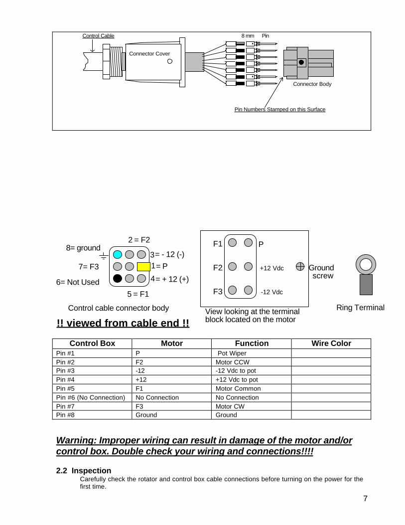
1.1 Display/Preset Circuit Board
The display/preset circuit board is mounted inside the control box in vertical position on the back ofthe control box front panel. A three digit, 7 segment display is driven by two microcontrollers withspecial software. The voltage on the wiper of the potentiometer (P) that is mounted in the motorassembly is applied to DC amplifier IC1 through terminal (v.p.). The proper voltage level is set bytrimmer tr1. This calibrated voltage is fed to a digital to analog converter. The digital information isprocessed by one of the microcontrollers to generate the bearing readout.You can monitor the voltage applied to the A/D (digital to analog converter) by shutting the controlbox off and depressing the paddle in the CW direction while turning the control box power back on.Three horizontal bars will start to flash on the display. Release the paddle and a relative voltage willbe displayed (relative voltage mode). The chart below is a guide showing the display readingverses the bearing. Note that the decimal point/points are not in the correct position – this is arelative reading. The actual voltage applied to the A/D is 0.00 Vdc at 110° and 5.00 Vdc at 240°.The direction paddle can be used to turn the rotator in this mode and the display will indicate therelative A/D voltage. Remember, this is the voltage applied to the A/D and not the potentiometervoltage (P) that is fed from the motor assembly to the control box although these voltages areproportional. To get out of the relative voltage mode, turn the control box off.
00.0. 25.0 5.0.0
110
07.0
000 240
43.0
180 180270 090
34.016.0Display
Deg.
CCW CWNS SW E
Limit Limit
Display Readout vs. Bearing
Relative Voltage Mode
1.2 OverlapThe display will also indicate whether or not you are in the overlap mode. If you are turning in theCW direction (east to south) and pass 180°, the left decimal point will light. If you are turning in theCCW direction (west to south) and pass 180°, the right decimal point will light.
1.3 Preset FunctionThe preset control may be used to turn the rotator in lieu of the paddle. The preset knob can berotated in either direction and has no stops. To preset a bearing, rotate the preset knob to thedesired direction (the preset may be set within 3°). As you rotate the knob, the three decimal pointson the display will start to flash and preset bearing will be displayed. After you have set the desiredpreset bearing, there will be a slight delay and the display will indicate the actual antenna bearingThe rotator will turn and the display will follow the antenna direction until it arrives at the presetbearing.
CW Overlap CCW Overlap

18
2 Pre-installation Check.Before you connect the rotator control cable to control box, switch on the control box, and thedisplay should indicate approximately 110°. Switch off the control box and connect the rotatorcontrol cable. The display should indicate approximately 110°. Rotate the preset knob to 000°. Aftera slight delay the rotator should turn in the CW direction and stop at 000°. Verify that the rotator isoperating properly. Check both directions of rotation, both electronic limits and the preset function.
3 000° Calibration ProcedureIf the initial antenna alignment is not correct, you can set it by adjusting trimmer TR4 located on themain board (see figure below). The correction range is about ±15°. Follow the steps listed below.
1 - Remove the control box top cover.2 - Turn trimmer TR4 (located on the main board) to maximum CCW.3 - Switch on the control box in the “relative voltage mode” (see 1.1 above).Using the paddle, rotatethe rotator until the display indicates a relative voltage of “00.0.”.4 - Turn TR4 in CW direction until the display indicates a relative voltage of “01.5”.5 - Using the paddle, rotate the rotator so the display indicates a relative voltage of “00.0.”.6 – Make reference marks on the rotator plate and rotator body. Using the paddle, rotate the rotatorone full turn until the reference marks align. The display should indicate a relative voltage of “36.0”.Ifit does not, slowly adjust trimmer TR1 (located on the display/preset board) until the displayindicates “36.0”.7 – Using the paddle, rotate the rotator until the display indicates a relative voltage of “25.0”. Turnthe control box off and turn it back on. The display should indicate a bearing of 000°.
The control box is now calibrated and the rotator is ready for installation. If you experience a smallerror in the antenna bearing after installation, you can make up to a ±10° correction by adjustingtrimmer TR4 . It may be necessary to go through the above 000° alignment procedure if you havesignificant error with the antenna rotated 360°.

19
Front
Power Transformer
Display/preset circuit board
AC Filter
Main Board
Back
Model B Control Box (Top View)
1
23
TR4
Display/Preset Board tr1
TR2

20
Appendix 2Model “C” Control Box
Features:• Voice synthesizer• Keypad command entry• 9 memories• Selectable soft start and soft stop• +70° and –70° rotation overlap (total rotation range of 500°)• Manual command with reverse delay• RS232 computer control compatible• Selectable north or south stop
Warning: The control box is complex. Follow the instructions described below. Beforemounting the rotator in the tower, thoroughly test the rotator on the ground and verifyproper operation of the motor and control box functions.
Power
1 2 3
4 5 6
7 8 9
0 #*
_ 0
ccw - mem reset cw - enter
Preset-Mem Bearing AF gain
8 digit LCD
Computer controlled antenna rotator
PRO.SIS.TEL.Rotator control box
Made in italy
Control Box Front Panel
1. CPU/Indicator PC Board
+12Vdc (Af power supply)
CPUISD
123456
dip switchR
ic icic ic
icicic
1
26
71
35
4 J5
J6
J3
123456 GND
+5Vdc (power supply)
U signal inCCW outCW out
J5 connections
J6 = loudspeaker
J3 connections (RS232)1 Data in2 Data out4 GND
CPU Circuit Board

21
The CPU/Indicator circuit board is vertically mounted on the back of the front panel.The eight digit LCD display is driven by a microcontroller and displays the antennabearing.
The voltage on the wiper of the potentiometer (U) that is mounted in the motorassembly is applied to a DC amplifier . The proper voltage level is set by trimmerTR2. This calibrated voltage is fed to a digital to analog converter. The digitalinformation is processed by one of the microcontrollers to generate the bearingreadout. Note that the “Vdc” values are relative.
000 250 500
110
070
000 240
430
180 180270 090
340160Vdc
Deg.
East WestNS SW E
Limit Limit
South Stop
000 250 500
290
070
180 070
430
000 000090 270
340160Vdc
Deg.
West EastSN NE W
Limit Limit
North Stop
When the dc voltage coming from the rotator motor potentiometer is 0 Vdc, the displaywill indicate 110° when configured for South Stop (default) and 290° when configured fora North Stop. If the rotator potentiometer wiper is at 2.5 Vdc, the display will indicate000° when configured with a south stop and 180° when configured for a north stop.
If you desire to read the relative dc voltage, switch the control box off . Press and holdtheCCW-MEM key while turning on the power. Release the key after the bearing isdisplayed. The left side of the display will indicate the potentiometer wiper voltage. Notethat the display will indicate the relative dc voltage, i.e. when the actual voltage is 2.50Vdc the display will indicate “250”. This function can be used to check for properoperation of the rotator potentiometer and initial antenna alignment. To return the controlbox back to normal operation, press the “0” key (reset).
2 – Pre-installation CheckDo not connect the control cable to the control box. Turn the control box on an thedisplay will indicate “WARM UP” followed by music from the speaker. Verify that thedisplay indicates a bearing of 110° for south stop or 290° for a north stop. Switch thecontrol box off and connect the control cable. Turn the control box on and the display

22
should indicate approximately 110 or 290° depending on depending on thepotentiometer position inside the motor unit. Press the “0” key (entering 00 or 000 givethe same results) and then press “enter”. The rotator will start to turn in the clockwise(CW) direction and stop when the display indicates 000° . While the rotator is turning,an arrow will flash on the right side of the display.
3 - Electronic Bearing Alignment (000° set)Discrepancy between the actual antenna bearing and the bearing displayed on thecontrol box can be corrected. Corrections up to ±15° can be made using the followingprocedure.1- Remove the top cover of the control box.2- Turn trimmer TR4 in the CCW direction until it hit the end of its travel.3- Turn the control box on in the “relative dc voltage” mode.4- Turn the rotator until the left display reads “000”.5- Turn trimmer TR4 clockwise (CW) until the display reads “015”.6- Turn the rotator again so that the left display reads “000”.7- Make reference marks on the rotator body and the mast mounting plate. Turn the
rotator 1 full turn until the marks realign. The left display should read "360”. If it doesnot, adjust TR2 so that the left display reads “360”.
front
Power trasformer
Display/preset circuit board
AC filter
Main board
back
Control box top view1
2-(500 adj)
3-(000 adj)
CPU/indicator circuit board
TR4TR2
4 – Voice SynthesizerAll voice commands are preset and in memory. The synthesized voice repeats thecommand via the front panel speaker. The volume control is located on the front panel.This function is convenient for the visual impaired.
5 – Keypad FunctionsKey pad allows you to enter the following commands:Preset, call memory, write memory, reset memory, reset command, CW and CCWmanual commands. If you press the same key number (1-9) 4 times or 4 different keynumbers (1-9), the last key stroke will resent the command.
23
- Manual Bearing Entry:The desired bearing may be manually entered. Enter the desired bearing by depressingthe 3 keypad digits. A bearing between 000 and 359 may be selected. The display willshow the wanted bearing. Press enter key. The rotator will start rotation in the directionof the shortest travel between the present position and the manually entered bearing.
- Entering a Bearing in Memory (Write/Rewrite memory)Nine (9) bearings may be stored in memory. The locations are 1 through 9 (not 0). Turnthe rotor on the desired bearing to be entered in to memory. Depress and hold thedesired memory location key (1 through 9 – not 0) for 3 seconds. This bearing is now inmemory. A memory position may be overwritten by repeating the above procedure.
- Recall MemorySelect and press the memory location number (1 through 9). Press the “mem” key. Thedisplay will show the position stored in the memory. Press enter to execute.
- Reset MemoryTurn the control box off. Press and hold the “0” key while switching the control box on,keeping the “0” key depressed for at least 3 seconds. Release the “0” key and thedisplay will show “RESET ME”. Press enter to reset all 9 memories.
- Reset commandAny command that is being executed may be reset or stopped by depressing the “0”key.
-Manual CCW-CW RotationManual rotation can be executed by depressing and holding the “*” key for CCWrotation, or the “#” key for CW rotation. The control box provides a 3 second reversedelay in the manual mode.
6 - Soft Start - Soft StopWhen executing a manually entered bearing or a bearing located in memory, a soft start/soft stop feature is provided. The duration of the soft start/stop time is selectable via thesettings of DIP switch 2 and 3 located on the CPU board.
Switch 2 3on - on = Soft functions disabledoff - on = Minimum soft start/stop timeon - off = Nominal soft start/stop timeoff - off = Maximum soft start/stop time (default)
Minimum soft/start/stop time is provided when using the CW and CCW manualcommands.

24
7 - South stop - North stopSouth stop or north stop may be selected. DIP switch 1 located on the CPU boardselects this function.
on = South stop (default)off = North stop
8 - RS 232 Communication ProtocolRS232 allows you to control rotator from a computer via the DB9 connector located onthe control box rear panel.
OUTPUT COMMANDSChr$(2) = Clear bufferChr$(48)&Chr(57) = Any number between 0 to 359Chr$(48) = AbortChr$(13)(enter) = Go
Cannon DB9 connections:pin 2 = serial data outpin 3 = serial data inpin 5 = computer GND
NOTES:
The program software used to control the rotator functions is stored in the CPU (IC 2)memory. If CPU IC is removed, the software will be lost and the control box will notfunction and must be reinitialized.
When the control box is not powered, CPU memory back-up voltage is supplied via alarge capacitor located on the CPU board. To avoid the loss of the software, powershould be applied to the control box at least every 6 months. This will recharge theback-up capacitor. Should the control box not function after and extended unpoweredstorage period, it must be reinitialized.
To initialize the control box:Turn on the powerPress “555” and press the “cw enter” keyPress “819” and press the “cw enter” key

25
Appendix 3
Connector Information
8 mm PinControl Cable
Connector Cover
Connector Body
Pin Numbers Stamped on this Surface
Connector Cover: Mencom/ILME P/N CK-03VConnector Body: Mencom/ILME P/N CDM-07Connector Pin: Mencom/ILME P/N CDMA 2.5
Connector parts are available in the USA through:
Mencom Corporation1649 Oakbrook Dr.Gainesville, GA 30507Ph: 770-534-4585
Midwest distributor is:
Affiliated Control640 Wheat Ln.Wood Dale, IL 60191Ph: 630-595-4680
Rev. 2001-12A


![12a -OilFieldSafetyNEO1[1]..](https://static.fdocuments.in/doc/165x107/55cf97e3550346d03394398e/12a-oilfieldsafetyneo11.jpg)