Proposal - Weebly · Project Proposal 2 1 - Problem Formulation, Metrics and Values 1.1 - Overall...
41
AER201: Engineering Design
Transcript of Proposal - Weebly · Project Proposal 2 1 - Problem Formulation, Metrics and Values 1.1 - Overall...

AER201: Engineering Design
Project Proposal
Monsters, Inc. (#11) Antonina Gorshenina
Jihad El Sheikh
Rabab Haider
Submission date: Friday, January 30
th, 2015
Instructors: Cameron Robertson
Todd Reichert
Victor Ragusila
Teaching Assistant: Nikhil Sharma
AER201: Engineering Design January 30th
, 2015
Project Proposal
Table of Contents
Executive Summary ........................................................................................................................ 1
1 - Problem Formulation, Metrics and Values ................................................................................ 2
1.1 - Overall objective ................................................................................................................. 2
1.2 - Requirements and Constraints ............................................................................................. 2
1.3 - Team goals .......................................................................................................................... 2
1.4 - Team values ......................................................................................................................... 2
2 - Background Survey .................................................................................................................... 3
2.1 - Electromechanical designs .................................................................................................. 3
2.2 - Sensors ................................................................................................................................. 4
2.3 - Localization ......................................................................................................................... 5
3 - Familiarization ........................................................................................................................... 6
3.1 - Motors ................................................................................................................................. 6
3.2 - Sensors ................................................................................................................................. 6
3.3 - Code structure ...................................................................................................................... 6
4 - Development of Robot Design: Functional Decomposition ...................................................... 7
4.1 - Electromechanical subsystems ............................................................................................ 7
4.2 - Circuit subsystems ............................................................................................................... 7
4.3 - Microcontroller subsystems ................................................................................................ 7
5 - Conceptualization ....................................................................................................................... 8
5.1 - Base Designs ....................................................................................................................... 8
5.2 - Stage Designs ...................................................................................................................... 8
5.3 - Retriever Designs ................................................................................................................ 9
5.4 - Lift mechanism .................................................................................................................... 9
5.5 - Release mechanism ........................................................................................................... 10
5.6 - Navigation ......................................................................................................................... 11
5.7 - Game strategy .................................................................................................................... 11
6 - Prototyping ............................................................................................................................... 12
6.1 - Development of the Base .................................................................................................. 12
6.2 - Detailed Analysis of the Stage .......................................................................................... 13
6.3 - Development of the Retriever ........................................................................................... 14
6.4 - Lift and Release Mechanisms ............................................................................................ 15
6.5 - Integrating Circuits with Motors ....................................................................................... 15
AER201: Engineering Design January 30th
, 2015
Project Proposal
6.6 - Circuit Development ......................................................................................................... 17
6.7 - Integration and Use of Sensors .......................................................................................... 18
6.8 - Code structure .................................................................................................................... 19
7 - Specification of Proposed Design ............................................................................................ 19
7.1 - Holistic Design .................................................................................................................. 19
7.2 - Electromechanical subsystem ............................................................................................ 21
7.3 - Circuit subsystem .............................................................................................................. 22
7.4 - Microcontroller subsystem ................................................................................................ 22
8 - Project Management ................................................................................................................ 23
8.1 - Timeline and project plan .................................................................................................. 23
8.2 - Division of labour .............................................................................................................. 24
8.3 - Budget ............................................................................................................................... 24
9 - Conclusion ............................................................................................................................... 25
Appendix A: Conceptual design sketches ..................................................................................... 26
Appendix B: Prototype and Concept Summary Charts ................................................................. 29
Table 1: Base Summary Chart: Overall Concepts ..................................................................... 29
Table 2: Base Summary Chart: Wheels and casters .................................................................. 29
Table 3: Retriever Summary Chart ............................................................................................ 30
Appendix C: Additional Prototyping Images ................................................................................ 31
Appendix D: Comparison Charts .................................................................................................. 32
Appendix E: Data and Processing Flowcharts .............................................................................. 33
Flowchart 1: Code design: Using Odometry ............................................................................. 33
Flowchart 2: Code design: Line Detecting Sensors ................................................................... 34
Flowchart 3: State Diagram ....................................................................................................... 35
Appendix F: Arduino pins ............................................................................................................. 35
Appendix G: Project Timeline ...................................................................................................... 36
Appendix H: Works Cited List ...................................................................................................... 37
AER201: Engineering Design January 30th
, 2015
Project Proposal
1
Executive Summary
This project proposal will guide the reader through the design process of Monsters, Inc. in
developing an autonomous robot to compete in the annual AER201 Engineering Design
competition for 2015. The challenge, to build a robot that plays a modified version of Connect
Four, requires a thorough understanding of the game rules, identification of any budget, weight
and dimensional constraints, and familiarization of the field of play and gameboard.
As a first step, Monsters, Inc. established team objectives and goals, to provide a
framework to design a winning robot, to aid in assessing multiple designs, and to justify
decisions made. A foundation of knowledge was then built, through the research of existing ideas
and solutions. Both homemade autonomous robot projects and industrial robots were looked into,
and components and approaches to tackling the numerous tasks were analyzed. These designs
could be used both as they are, and as a basis for further development, thus saving time which is
better spent in testing conceptual ideas. The details of the early survey are outlined in this report.
After gathering theoretical knowledge of designs and components, practical
familiarization of the components and materials at hand was essential. This was completed in
parallel with early prototyping models, in order to better understand the optimal operational
ranges for electronic components. Experimentation was a vital step in the project to build the
skills needed for the project. Monsters, Inc. recorded all information gathered from
experimentation and testing, and a comprehensive summary of the lessons learnt and notes taken
has been included in the project proposal. Conceptual design sketches, prototyping images and
summary charts are included in the Appendices as additional reference information.
The final design of the robot was decided upon after comparing the prototypes with
selected criteria that best meet the team goals. The moving base comprises of 2-wheel differential
steering powered by DC motors and a ball caster. Supported by the base, the ball retriever
mechanism is comprised of a rotating clutch system, driven by a servo motor. The retriever is
attached to an arm which rotates around an elevated axle, by means of a DC motor, and deposits
the ball onto a ramp and into the gameboard. The robot will be fully capable of navigating on the
playing field and locating itself relative to markers such as the hoppers, gameboard and walls.
The primary navigation techniques rely on the detection of grid lines for orientation and the use
of ultrasonic sensors for positioning feedback.
The project has been mapped out via a Gantt chart to visualize the timeline and to meet
the goals of the progress evaluations and final competition. By progress evaluation I, a functional
base will be capable of mobilizing and detecting nearby objects. By progress evaluation II, the
robot will be able to navigate the gameboard, avoid obstacles and pick up balls. By progress
evaluation III, the full project will be completed and the focus will be directed towards perfecting
the design and ensuring the robot’s robustness. Communication between the team members is to
be established frequently to ensure that the team shares the same vision and work on compatible
products.
AER201: Engineering Design January 30th
, 2015
Project Proposal
2
1 - Problem Formulation, Metrics and Values
1.1 - Overall objective
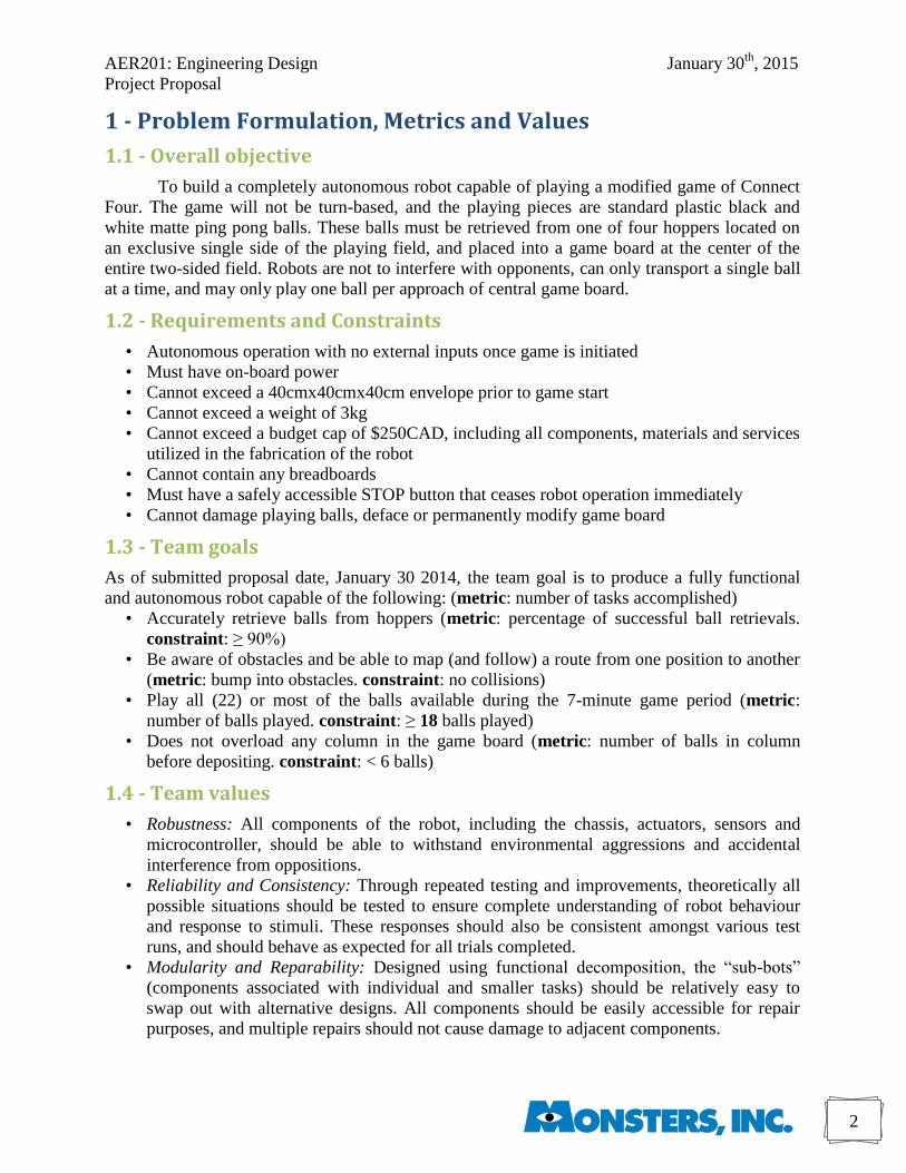
To build a completely autonomous robot capable of playing a modified game of Connect
Four. The game will not be turn-based, and the playing pieces are standard plastic black and
white matte ping pong balls. These balls must be retrieved from one of four hoppers located on
an exclusive single side of the playing field, and placed into a game board at the center of the
entire two-sided field. Robots are not to interfere with opponents, can only transport a single ball
at a time, and may only play one ball per approach of central game board.
1.2 - Requirements and Constraints
• Autonomous operation with no external inputs once game is initiated
• Must have on-board power
• Cannot exceed a 40cmx40cmx40cm envelope prior to game start
• Cannot exceed a weight of 3kg
• Cannot exceed a budget cap of $250CAD, including all components, materials and services
utilized in the fabrication of the robot
• Cannot contain any breadboards
• Must have a safely accessible STOP button that ceases robot operation immediately
• Cannot damage playing balls, deface or permanently modify game board
1.3 - Team goals
As of submitted proposal date, January 30 2014, the team goal is to produce a fully functional
and autonomous robot capable of the following: (metric: number of tasks accomplished)
• Accurately retrieve balls from hoppers (metric: percentage of successful ball retrievals.
constraint: ≥ 90%)
• Be aware of obstacles and be able to map (and follow) a route from one position to another
(metric: bump into obstacles. constraint: no collisions)
• Play all (22) or most of the balls available during the 7-minute game period (metric:
number of balls played. constraint: ≥ 18 balls played)
• Does not overload any column in the game board (metric: number of balls in column
before depositing. constraint: < 6 balls)
1.4 - Team values
• Robustness: All components of the robot, including the chassis, actuators, sensors and
microcontroller, should be able to withstand environmental aggressions and accidental
interference from oppositions.
• Reliability and Consistency: Through repeated testing and improvements, theoretically all
possible situations should be tested to ensure complete understanding of robot behaviour
and response to stimuli. These responses should also be consistent amongst various test
runs, and should behave as expected for all trials completed.
• Modularity and Reparability: Designed using functional decomposition, the “sub-bots”
(components associated with individual and smaller tasks) should be relatively easy to
swap out with alternative designs. All components should be easily accessible for repair
purposes, and multiple repairs should not cause damage to adjacent components.

AER201: Engineering Design January 30th
, 2015
Project Proposal
3
• Maneuverability and speed: Robot should be able to move around the playing field easily
and fast enough to play the minimum number of balls (play ≥ 18 balls). It should be able to
avoid obstacles and access hoppers and the game board without having to re-approach
targets if needed (i.e. rotation or reorientation in place)
• Simplicity: The robot need not be complex. Rather, the easiest solutions are preferred: easy
to design, construct and implement. For example, complex navigation systems that leave
room for error are to be avoided. Completing the job is more important than creativity.
2 - Background Survey
To gain a better understanding of the project challenges, existing robots (both commercial and
hobbyist) were researched, thus providing a foundation of knowledge for Monsters, Inc..
2.1 - Electromechanical designs
Vex robotics kits and designs were used as a starting point for design research, particularly for
the electromechanical subsystem. Analysis of projects in the “Vex Machinations: A Step-by-Step
Project Guide, Version 1.0” [1] are as follows:
• Flexigearbot: 2-wheel indirect drive shows the method of driving wheels with two DC-
motors and gears. Gear ratios were used to control motor speed. With a given DC-motor, a
range of speeds can be achieved by gearing up (or down) the drive axle. This also
highlighted the trade-off between speed and torque.
• Ping Pong Shooter: use of intake rollers (two adjacent gears) in grabbing objects.
• Animal Grabber: design of a grabber using adjacent gears. The associated lifting
mechanism resembles the rotating-arm concept being developed (see Section 5). Potential
drawbacks include the use of multiple gears (added mechanical complexity), and the torque
requirement on the motor. The design may need to gear down the motor to increase torque.
• Autonomous robots: use of bumper sensor, ultrasonic (proximity) sensor, limit sensor
Consistencies in these robot designs include the use of gears to adjust power requirements and to
enable power transmission. Additionally, the use of aluminum chassis rails to produce a robot
consisting of only frames allowed for a higher strength to weight ratio, and secure connections
with screws, nuts and bolts. The placement of motors, sensors and microcontrollers was also well
planned – something that should be thought about before construction.
Another robot studied was a design project by a Berkeley team for a ME102 Design Course,
labelled the “Bear Claw Tennis Ball Collector”. Similarities in the tasks required included
avoidance of obstacles, and retrieval and storage of balls. The design involved a claw and
rotating arm both controlled by servo motors, and a camera to view the surroundings. Key
features included the sheltering of the microcontroller, camera and sensitive circuitry – all crucial
for a robust design. The use of a servo motor to rotate the camera to eliminate the need for entire
chassis movement was a great solution to the accessibility limitations of a fixed camera. [2]
Packaging robots: the robotic system introduced by the Wisconsin Cheese Group, where the
robot uses a vacuum suction gripper as a tool to pick up a variety of objects from the conveyor
belt was also viewed briefly. Employing camera-based technologies, the M430iA/2F robotic
AER201: Engineering Design January 30th
, 2015
Project Proposal
4
system aids in the packaging of goods, and also checks to make sure objects in the packaging line
are placed in the correct orientation. [3]
Most robots researched used DC motors for primary locomotion. Many robots had two wheel
differential steering and a ball caster. Homemade 4-wheeled robots used front-wheel drive. Most
wheels were driven directly by the motors, suggesting lower chance of mechanical and
construction errors. Many tutorials also stressed the importance of avoiding driving a larger gear
with a smaller one, as this can damage the DC motor’s internal gearbox. A range of DC and high-
and low-torque servo motors were used to control rotational motion of arms and grabber
components. The chassis is often made of aluminum rails for sturdy frames, and metal sheets
(moderate to high cost) or wood (low to moderate cost) to support other components.
2.2 - Sensors
Since the robot is to be fully autonomous, different sensors were researched to help determine
their ability to accurately relay information from the playing field given the environment of play.
The following information was gathered:
IR reflective sensor:
Function IR light is sent out by the emitter, then a receiver detects the percentage of light reflected by
the surface [4].
Darker surfaces reflect less light than lighter surfaces.
Implementation Line following: it will be easy to distinguish between the black grid lines on the playing
field and white background. The robot will move the wheels on one side until the sensor on
that side detects a black line. Then, the wheels on the other side will turn until their
respective sensor detects a white line. This back-and-forth control will continue, resulting in
the robot zigzagging along the line.
Possible problems Robot doesn’t move in a straight line, which would take more time to reach its destination.
The lines on the playing field are in grids, which would confuse the robot when it reaches an
intersection, and would end up with it moving around a square boundary.
IR Proximity sensors:
Function The sensor emits a pulse of light towards a surface and detects the reflected pulse. Based on
the angle of emission and detection, it uses triangulation to determine the distance of the
object in front of it [5].
Implementation They can be used for object detection
Possible problems Cannot be used outdoors because sunlight interferes with the rays emitted by the sensor. The
readings for objects at the same distance may vary based on shape, material or colour.
Ultrasonic sensor:
Function Uses a type of sonar detection where the sensor emits a sound wave and detects it after it
reflects off of an object. It measures the time between emission and detection, and uses the
speed of sound to calculate the distance to the object [6].
Implementation They can be used for object detection.
Possible problems It is not accurate in detecting different objects that are close together.
It can’t distinguish between walls and corners.
AER201: Engineering Design January 30th
, 2015
Project Proposal
5
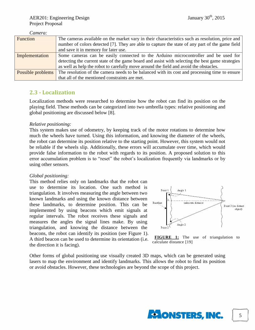
FIGURE 1: The use of triangulation to
calculate distance [19]
Camera:
Function The cameras available on the market vary in their characteristics such as resolution, price and
number of colors detected [7]. They are able to capture the state of any part of the game field
and save it in memory for later use.
Implementation Some cameras can be easily connected to the Arduino microcontroller and be used for
detecting the current state of the game board and assist with selecting the best game strategies
as well as help the robot to carefully move around the field and avoid the obstacles.
Possible problems The resolution of the camera needs to be balanced with its cost and processing time to ensure
that all of the mentioned constraints are met.
2.3 - Localization
Localization methods were researched to determine how the robot can find its position on the
playing field. These methods can be categorized into two umbrella types: relative positioning and
global positioning are discussed below [8].
Relative positioning:
This system makes use of odometry, by keeping track of the motor rotations to determine how
much the wheels have turned. Using this information, and knowing the diameter of the wheels,
the robot can determine its position relative to the starting point. However, this system would not
be reliable if the wheels slip. Additionally, these errors will accumulate over time, which would
provide false information to the robot with regards to its position. A proposed solution to this
error accumulation problem is to “reset” the robot’s localization frequently via landmarks or by
using other sensors.
Global positioning:
This method relies only on landmarks that the robot can
use to determine its location. One such method is
triangulation. It involves measuring the angle between two
known landmarks and using the known distance between
these landmarks, to determine position. This can be
implemented by using beacons which emit signals at
regular intervals. The robot receives these signals and
measures the angles the signal lines make. By using
triangulation, and knowing the distance between the
beacons, the robot can identify its position (see Figure 1).
A third beacon can be used to determine its orientation (i.e.
the direction it is facing).
Other forms of global positioning use visually created 3D maps, which can be generated using
lasers to map the environment and identify landmarks. This allows the robot to find its position
or avoid obstacles. However, these technologies are beyond the scope of this project.
AER201: Engineering Design January 30th
, 2015
Project Proposal
6
3 - Familiarization
Before deciding upon the components to be used, basic testing was carried out for functionality,
range and limitations of different parts. Collected information is summarized below.
3.1 - Motors
DC motor, servo motor, unipolar stepper motor and bipolar stepper motor were tested and the
following observations were made.
DC motor:
• Connects easily to other components (including axles, shafts, wheels and gears)
• Involves simple circuitry: connecting both terminals of the motor to a power supply
• Can switch rotary direction by reversing the voltage signs on the motor: physically by
swapping the wires on both terminals, or by using an H-bridge (no physical re-connection)
• Speed of the motor depends on the voltage applied (as well as the operational range of the
motor). To change the speed, a potentiometer can be used, enabling more control
• The amount of rotation cannot be controlled (i.e. by a number of degrees or a certain
number of steps). This is potentially problematic if the voltage from batteries is
inconsistent. Optical encoders can be used to determine the rotations of the shaft
• Often used for primary locomotion (connection to main wheels)
Servo motors:
• Provides more control over rotation: can specify the number of degrees to rotate
• Operates between 0-179°, which may constrain the design of controlled component
• Variety of servo arms allow for a range of component designs, and all are easy to connect
Bi-polar stepper motor:
• Requires an H-bridge to operate
• Rotates in increments called steps and can run continuously like a DC motor
• Size and weight constraints - generally large and heavy
Uni-polar stepper motor:
• Circuit is more complex than the bi-polar stepper; needs a transistor array chip to operate
• Rotates in increments called steps and can run continuously like a DC motor
• Smaller in size than the bi-polar stepper motor, but similar weight
3.2 - Sensors
Touch Sensor (switch): Touch sensors in a form of regular electrical switches were also tested for
possible future implementation. Both toggle and pushbutton switches were tried against the
gameboard, and both types were successful at detecting the presence of the ball in the column.
This feature could potentially be added to the arm of the robot to check if any of the columns in
the gameboard are full.
3.3 - Code structure
In order to gain some familiarization with the electrical components mentioned above, different
small programs were written for each, and they were bench-tested. At first, the code was taken
from the Arduino Beginner’s book provided in the kit, and then other resources were used as
more components were tested. The main resources were the Arduino Cookbook and the Arduino
online community support. Running the code once was not enough to explore the full
AER201: Engineering Design January 30th
, 2015
Project Proposal
7
functionality of the component, but instead, once the code was proven to work, it was
manipulated to try different functions of the components. This was done to explore how the code
interacts with the components and assess the use of each as summarized in the previous section.
These tests have helped in designing the prototypes and forming the conceptual designs that will
be discussed in subsequent sections.
4 - Development of Robot Design: Functional Decomposition
When developing the robot design, the system of functional decomposition was used to break the
design into subsystems which each completed a specific task required in the overall function of
the robot. Divisions are as follows:
4.1 - Electromechanical subsystems
● Base for main structural support and for movement around the playing field. The base
will likely house the driving motors
● Stage as an additional point of motion to eliminate complex coordination from the base
when aligning with hoppers and the gameboard. The stage (or base, if a stage is not used)
houses the retriever, lift and release mechanisms. This subsystem is optional.
● Retriever for capturing balls from the hoppers
● Lift mechanism to raise the retrieved ball to the height of the gameboard
● Release mechanism to play the ball into the gameboard
4.2 - Circuit subsystems
● Locomotive circuitry includes the circuit system involved with the Primary locomotion
(see micro-controller subsystem) and the Base (and Stage if applicable).
● Advanced circuitry includes the circuit system involved with any interaction with the ping
pong balls, and the Advanced coordination (see micro-controller subsystem)
● Positioning sensors will provide information of the robot’s location in the play field
4.3 - Microcontroller subsystems
● Primary locomotion includes the function of obstacle detection. This area governs the
navigation of the robot around the playing field, using inputs from the sensors and/or
mechanical responses.
● Advanced coordination will control all motion and behaviour of the robot, excluding the
Primary locomotion. This includes, but is not limited to, ball retrieval, lift and release.
● Game strategy includes processing of information regarding the state of the gameboard,
and making decisions on where to play the next ball and how to proceed.
AER201: Engineering Design January 30th
, 2015
Project Proposal
8
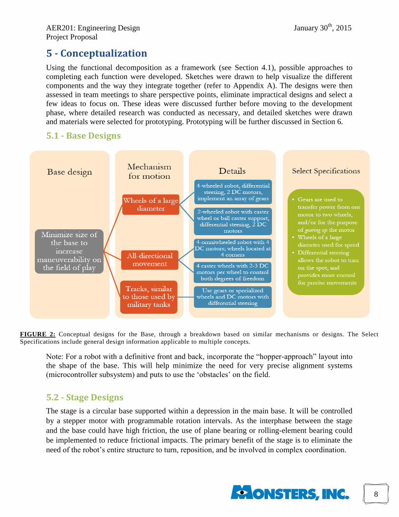
FIGURE 2: Conceptual designs for the Base, through a breakdown based on similar mechanisms or designs. The Select
Specifications include general design information applicable to multiple concepts.
5 - Conceptualization
Using the functional decomposition as a framework (see Section 4.1), possible approaches to
completing each function were developed. Sketches were drawn to help visualize the different
components and the way they integrate together (refer to Appendix A). The designs were then
assessed in team meetings to share perspective points, eliminate impractical designs and select a
few ideas to focus on. These ideas were discussed further before moving to the development
phase, where detailed research was conducted as necessary, and detailed sketches were drawn
and materials were selected for prototyping. Prototyping will be further discussed in Section 6.
5.1 - Base Designs
Note: For a robot with a definitive front and back, incorporate the “hopper-approach” layout into
the shape of the base. This will help minimize the need for very precise alignment systems
(microcontroller subsystem) and puts to use the ‘obstacles’ on the field.
5.2 - Stage Designs
The stage is a circular base supported within a depression in the main base. It will be controlled
by a stepper motor with programmable rotation intervals. As the interphase between the stage
and the base could have high friction, the use of plane bearing or rolling-element bearing could
be implemented to reduce frictional impacts. The primary benefit of the stage is to eliminate the
need of the robot’s entire structure to turn, reposition, and be involved in complex coordination.
AER201: Engineering Design January 30th
, 2015
Project Proposal
9
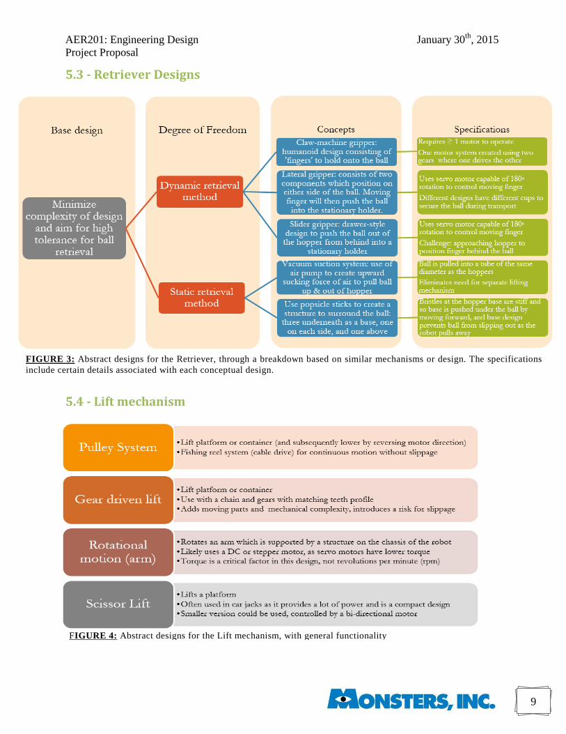
5.3 - Retriever Designs
5.4 - Lift mechanism
FIGURE 3: Abstract designs for the Retriever, through a breakdown based on similar mechanisms or design. The specifications
include certain details associated with each conceptual design.
FIGURE 4: Abstract designs for the Lift mechanism, with general functionality
AER201: Engineering Design January 30th
, 2015
Project Proposal
10
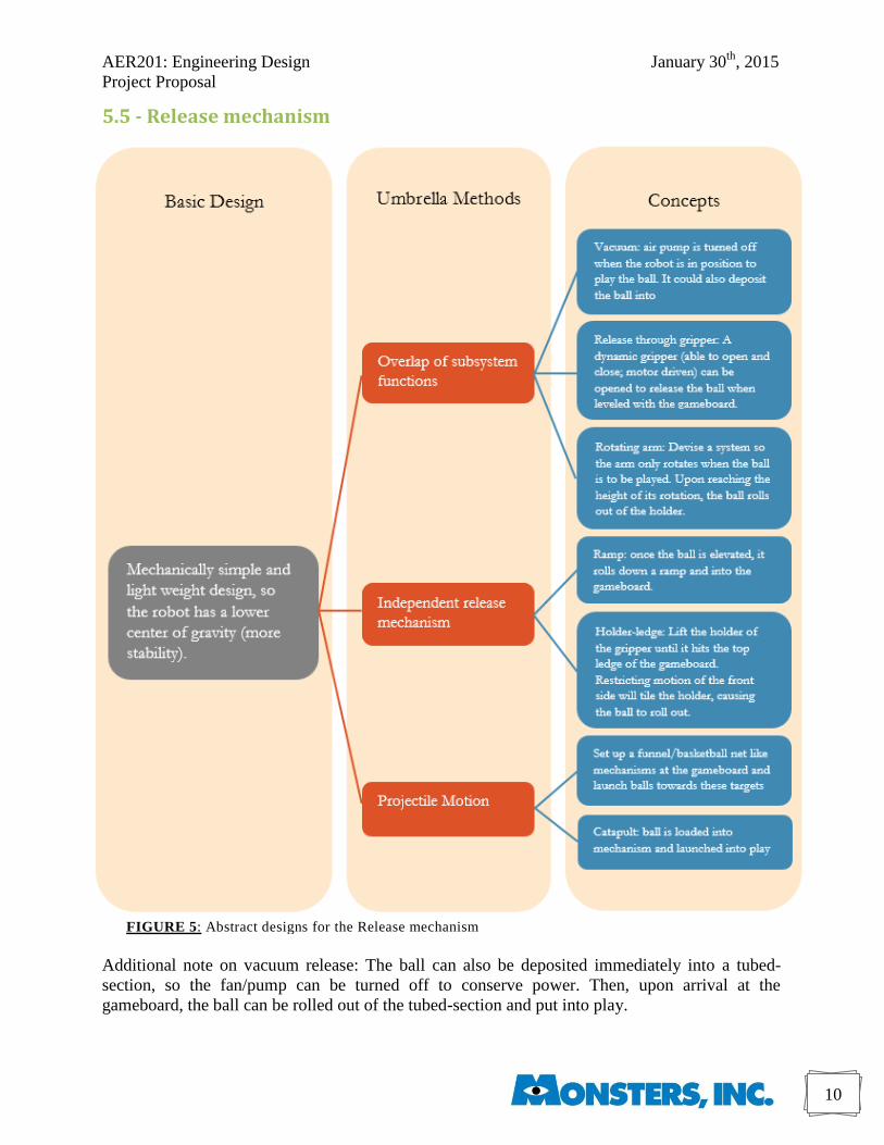
5.5 - Release mechanism
Additional note on vacuum release: The ball can also be deposited immediately into a tubed-
section, so the fan/pump can be turned off to conserve power. Then, upon arrival at the
gameboard, the ball can be rolled out of the tubed-section and put into play.
FIGURE 5: Abstract designs for the Release mechanism
AER201: Engineering Design January 30th
, 2015
Project Proposal
11
5.6 - Navigation
There are two main concept designs for navigation that are considered for this project. The
concepts for these are outlines below.
Odometry and pre-coded information:
All the paths (for example, going from starting position to hopper, going from hopper to game
board, and vice versa) that the robot could take would be hard-coded into its memory. Since the
driving motors of the wheels are DC motors, the order of the functions (ex. move forward, turn,
move backward) would be saved in an array, and the time needed for each function would be
saved in another one. A combination of functions would be carried out to follow certain paths.
However, odometry is not always a reliable method for tracking the robot’s movement. It cannot
precisely relay positional information if the wheels slip, and these errors would accumulate over
time. To address this issue, two ultrasonic sensors would be used to check and verify the position
of the robot when it is near walls, thus allowing it to correct its position. One sensor would be
facing the front of the robot, and the other would be facing its side.
Line detection:
The robot would use two colour sensors to detect the lines on the field to move around. It would
only make 90° turns in order to stay perpendicular to a set of lines on the field. The field is
divided into squares, which would help the robot to locate itself. The robot can update its position
as it crosses from one square into another. The robot would also use two ultrasonic sensors: one
facing the front and one facing the side. It would check its position (fixing it as needed) when it
is near a wall, using the readings from the sensor. Finally, odometry would be used to help the
robot navigate the short distances immediately around the hoppers; because it’s being used for
short distances only, there would not be an accumulation of error.
5.7 - Game strategy
Prevent column overflow:
The minimal goal to meet in terms of game strategy is to prevent the robot from adding a ball to
an already filled column. This can be implemented by adding a touch sensor (see section 3.2) to
check if the selected column is full. If it is, the robot would store this in its memory and align
itself with another column.
Sense the balls:
Going one step further, the robot can use a touch sensor to check for all the balls. It starts by
checking the lowest row in each column. If it finds a ball, it logs this into its memory and doesn’t
check for this position again. Next time it checks one row higher in each column, and if it detects
balls, it logs the positions in its memory. By knowing where it places its game pieces, the robot
can distinguish between its pieces and the opponent’s. This can allow the robot to develop
playing algorithm for the game, although the method takes a lot of time to implement.
Take a snapshot:
This concept relies on using a camera that can take a snapshot of the game upon each approach
and analyse the picture to determine the state of the game. Relying on this, the robot can use
algorithms to compute game strategies for optimal placement of the balls. This uses more
computing power, which might require the use of an additional microcontroller.
AER201: Engineering Design January 30th
, 2015
Project Proposal
12
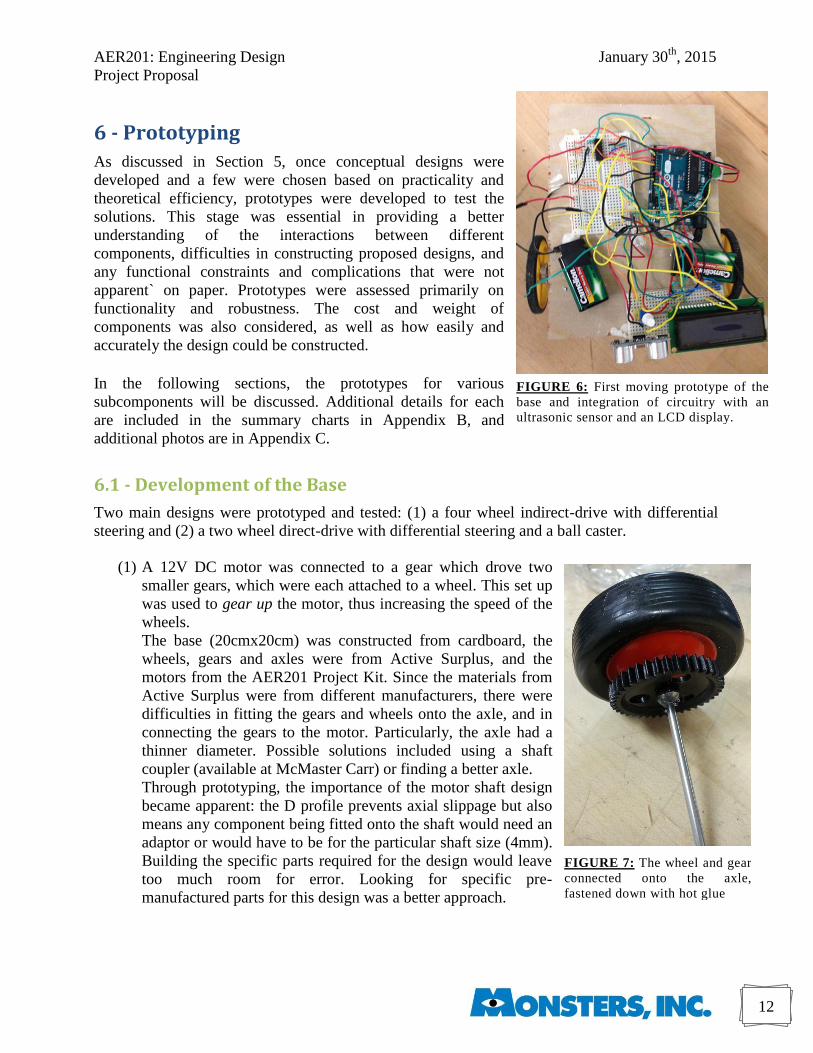
FIGURE 6: First moving prototype of the
base and integration of circuitry with an
ultrasonic sensor and an LCD display.
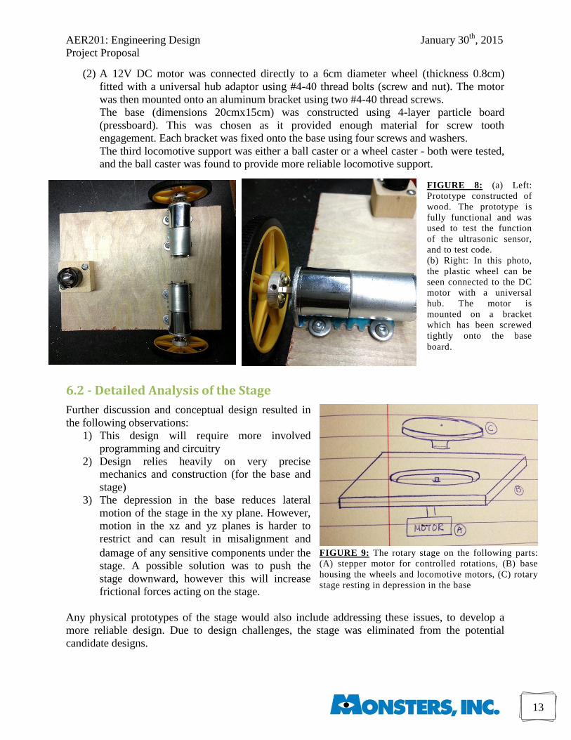
FIGURE 7: The wheel and gear
connected onto the axle,
fastened down with hot glue
6 - Prototyping
As discussed in Section 5, once conceptual designs were
developed and a few were chosen based on practicality and
theoretical efficiency, prototypes were developed to test the
solutions. This stage was essential in providing a better
understanding of the interactions between different
components, difficulties in constructing proposed designs, and
any functional constraints and complications that were not
apparent` on paper. Prototypes were assessed primarily on
functionality and robustness. The cost and weight of
components was also considered, as well as how easily and
accurately the design could be constructed.
In the following sections, the prototypes for various
subcomponents will be discussed. Additional details for each
are included in the summary charts in Appendix B, and
additional photos are in Appendix C.
6.1 - Development of the Base
Two main designs were prototyped and tested: (1) a four wheel indirect-drive with differential
steering and (2) a two wheel direct-drive with differential steering and a ball caster.
(1) A 12V DC motor was connected to a gear which drove two
smaller gears, which were each attached to a wheel. This set up
was used to gear up the motor, thus increasing the speed of the
wheels.
The base (20cmx20cm) was constructed from cardboard, the
wheels, gears and axles were from Active Surplus, and the
motors from the AER201 Project Kit. Since the materials from
Active Surplus were from different manufacturers, there were
difficulties in fitting the gears and wheels onto the axle, and in
connecting the gears to the motor. Particularly, the axle had a
thinner diameter. Possible solutions included using a shaft
coupler (available at McMaster Carr) or finding a better axle.
Through prototyping, the importance of the motor shaft design
became apparent: the D profile prevents axial slippage but also
means any component being fitted onto the shaft would need an
adaptor or would have to be for the particular shaft size (4mm).
Building the specific parts required for the design would leave
too much room for error. Looking for specific pre-
manufactured parts for this design was a better approach.
AER201: Engineering Design January 30th
, 2015
Project Proposal
13
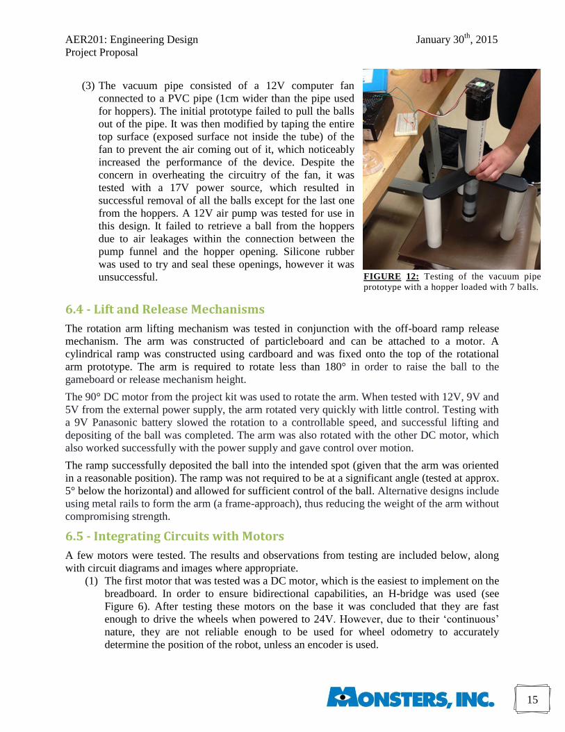
FIGURE 9: The rotary stage on the following parts:
(A) stepper motor for controlled rotations, (B) base
housing the wheels and locomotive motors, (C) rotary
stage resting in depression in the base
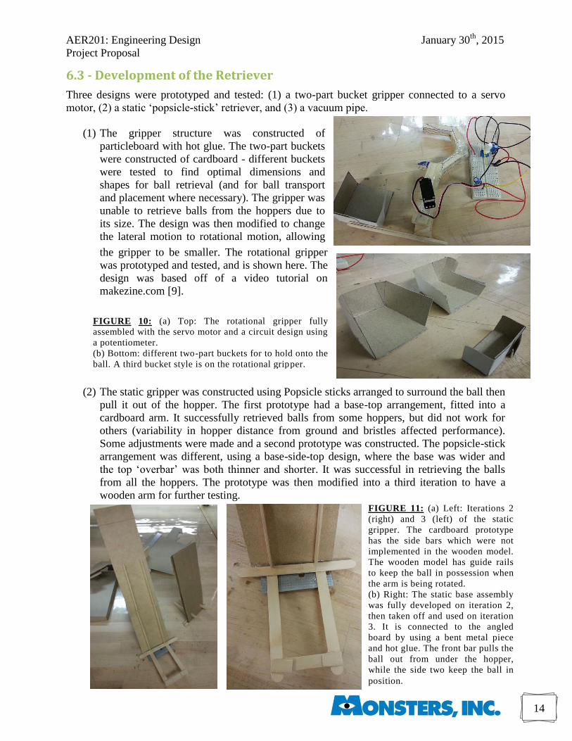
FIGURE 8: (a) Left:
Prototype constructed of
wood. The prototype is
fully functional and was
used to test the function
of the ultrasonic sensor,
and to test code.
(b) Right: In this photo,
the plastic wheel can be
seen connected to the DC
motor with a universal
hub. The motor is
mounted on a bracket
which has been screwed
tightly onto the base
board.
(2) A 12V DC motor was connected directly to a 6cm diameter wheel (thickness 0.8cm)
fitted with a universal hub adaptor using #4-40 thread bolts (screw and nut). The motor
was then mounted onto an aluminum bracket using two #4-40 thread screws.
The base (dimensions 20cmx15cm) was constructed using 4-layer particle board
(pressboard). This was chosen as it provided enough material for screw tooth
engagement. Each bracket was fixed onto the base using four screws and washers.
The third locomotive support was either a ball caster or a wheel caster - both were tested,
and the ball caster was found to provide more reliable locomotive support.
6.2 - Detailed Analysis of the Stage
Further discussion and conceptual design resulted in
the following observations:
1) This design will require more involved
programming and circuitry
2) Design relies heavily on very precise
mechanics and construction (for the base and
stage)
3) The depression in the base reduces lateral
motion of the stage in the xy plane. However,
motion in the xz and yz planes is harder to
restrict and can result in misalignment and
damage of any sensitive components under the
stage. A possible solution was to push the
stage downward, however this will increase
frictional forces acting on the stage.
Any physical prototypes of the stage would also include addressing these issues, to develop a
more reliable design. Due to design challenges, the stage was eliminated from the potential
candidate designs.
AER201: Engineering Design January 30th
, 2015
Project Proposal
14
FIGURE 10: (a) Top: The rotational gripper fully
assembled with the servo motor and a circuit design using
a potentiometer.
(b) Bottom: different two-part buckets for to hold onto the
ball. A third bucket style is on the rotational gripper.
FIGURE 11: (a) Left: Iterations 2
(right) and 3 (left) of the static
gripper. The cardboard prototype
has the side bars which were not
implemented in the wooden model.
The wooden model has guide rails
to keep the ball in possession when
the arm is being rotated.
(b) Right: The static base assembly
was fully developed on iteration 2,
then taken off and used on iteration
3. It is connected to the angled
board by using a bent metal piece
and hot glue. The front bar pulls the
ball out from under the hopper,
while the side two keep the ball in
position.
6.3 - Development of the Retriever
Three designs were prototyped and tested: (1) a two-part bucket gripper connected to a servo
motor, (2) a static ‘popsicle-stick’ retriever, and (3) a vacuum pipe.
(1) The gripper structure was constructed of
particleboard with hot glue. The two-part buckets
were constructed of cardboard - different buckets
were tested to find optimal dimensions and
shapes for ball retrieval (and for ball transport
and placement where necessary). The gripper was
unable to retrieve balls from the hoppers due to
its size. The design was then modified to change
the lateral motion to rotational motion, allowing
the gripper to be smaller. The rotational gripper
was prototyped and tested, and is shown here. The
design was based off of a video tutorial on
makezine.com [9].
(2) The static gripper was constructed using Popsicle sticks arranged to surround the ball then
pull it out of the hopper. The first prototype had a base-top arrangement, fitted into a
cardboard arm. It successfully retrieved balls from some hoppers, but did not work for
others (variability in hopper distance from ground and bristles affected performance).
Some adjustments were made and a second prototype was constructed. The popsicle-stick
arrangement was different, using a base-side-top design, where the base was wider and
the top ‘overbar’ was both thinner and shorter. It was successful in retrieving the balls
from all the hoppers. The prototype was then modified into a third iteration to have a
wooden arm for further testing.
AER201: Engineering Design January 30th
, 2015
Project Proposal
15
FIGURE 12: Testing of the vacuum pipe
prototype with a hopper loaded with 7 balls.
(3) The vacuum pipe consisted of a 12V computer fan
connected to a PVC pipe (1cm wider than the pipe used
for hoppers). The initial prototype failed to pull the balls
out of the pipe. It was then modified by taping the entire
top surface (exposed surface not inside the tube) of the
fan to prevent the air coming out of it, which noticeably
increased the performance of the device. Despite the
concern in overheating the circuitry of the fan, it was
tested with a 17V power source, which resulted in
successful removal of all the balls except for the last one
from the hoppers. A 12V air pump was tested for use in
this design. It failed to retrieve a ball from the hoppers
due to air leakages within the connection between the
pump funnel and the hopper opening. Silicone rubber
was used to try and seal these openings, however it was
unsuccessful.
6.4 - Lift and Release Mechanisms
The rotation arm lifting mechanism was tested in conjunction with the off-board ramp release
mechanism. The arm was constructed of particleboard and can be attached to a motor. A
cylindrical ramp was constructed using cardboard and was fixed onto the top of the rotational
arm prototype. The arm is required to rotate less than 180° in order to raise the ball to the
gameboard or release mechanism height.
The 90° DC motor from the project kit was used to rotate the arm. When tested with 12V, 9V and
5V from the external power supply, the arm rotated very quickly with little control. Testing with
a 9V Panasonic battery slowed the rotation to a controllable speed, and successful lifting and
depositing of the ball was completed. The arm was also rotated with the other DC motor, which
also worked successfully with the power supply and gave control over motion.
The ramp successfully deposited the ball into the intended spot (given that the arm was oriented
in a reasonable position). The ramp was not required to be at a significant angle (tested at approx.
5° below the horizontal) and allowed for sufficient control of the ball. Alternative designs include
using metal rails to form the arm (a frame-approach), thus reducing the weight of the arm without
compromising strength.
6.5 - Integrating Circuits with Motors
A few motors were tested. The results and observations from testing are included below, along
with circuit diagrams and images where appropriate.
(1) The first motor that was tested was a DC motor, which is the easiest to implement on the
breadboard. In order to ensure bidirectional capabilities, an H-bridge was used (see
Figure 6). After testing these motors on the base it was concluded that they are fast
enough to drive the wheels when powered to 24V. However, due to their ‘continuous’
nature, they are not reliable enough to be used for wheel odometry to accurately
determine the position of the robot, unless an encoder is used.
AER201: Engineering Design January 30th
, 2015
Project Proposal
16
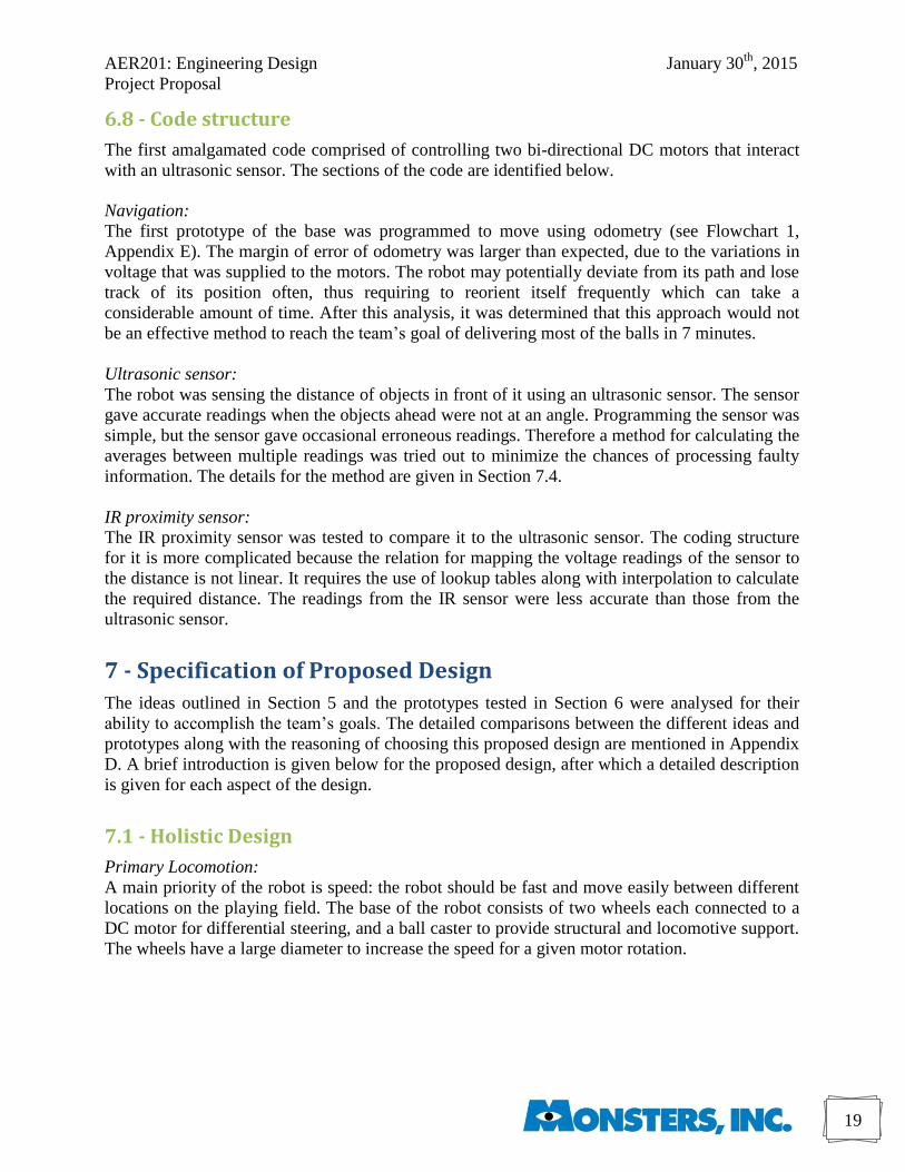
FIGURE 16: Servo motor implemented and
integrated with the rotating arm prototype
FIGURE 13: Circuitry for connecting
a bipolar stepper motor with an H-
bridge chip. FIGURE 14: Controlling a unipolar
stepper motor with Arduino
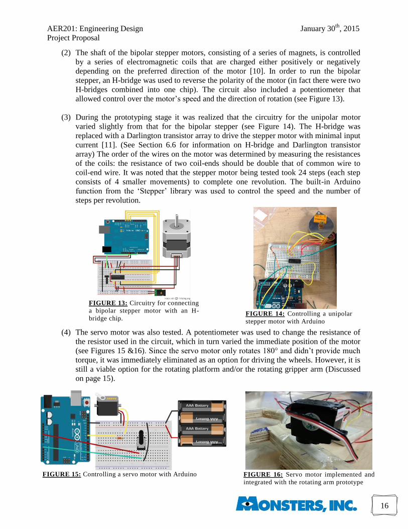
(2) The shaft of the bipolar stepper motors, consisting of a series of magnets, is controlled
by a series of electromagnetic coils that are charged either positively or negatively
depending on the preferred direction of the motor [10]. In order to run the bipolar
stepper, an H-bridge was used to reverse the polarity of the motor (in fact there were two
H-bridges combined into one chip). The circuit also included a potentiometer that
allowed control over the motor’s speed and the direction of rotation (see Figure 13).
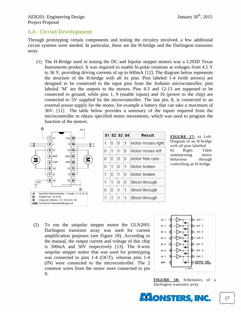
(3) During the prototyping stage it was realized that the circuitry for the unipolar motor
varied slightly from that for the bipolar stepper (see Figure 14). The H-bridge was
replaced with a Darlington transistor array to drive the stepper motor with minimal input
current [11]. (See Section 6.6 for information on H-bridge and Darlington transistor
array) The order of the wires on the motor was determined by measuring the resistances
of the coils: the resistance of two coil-ends should be double that of common wire to
coil-end wire. It was noted that the stepper motor being tested took 24 steps (each step
consists of 4 smaller movements) to complete one revolution. The built-in Arduino
function from the ‘Stepper’ library was used to control the speed and the number of
steps per revolution.
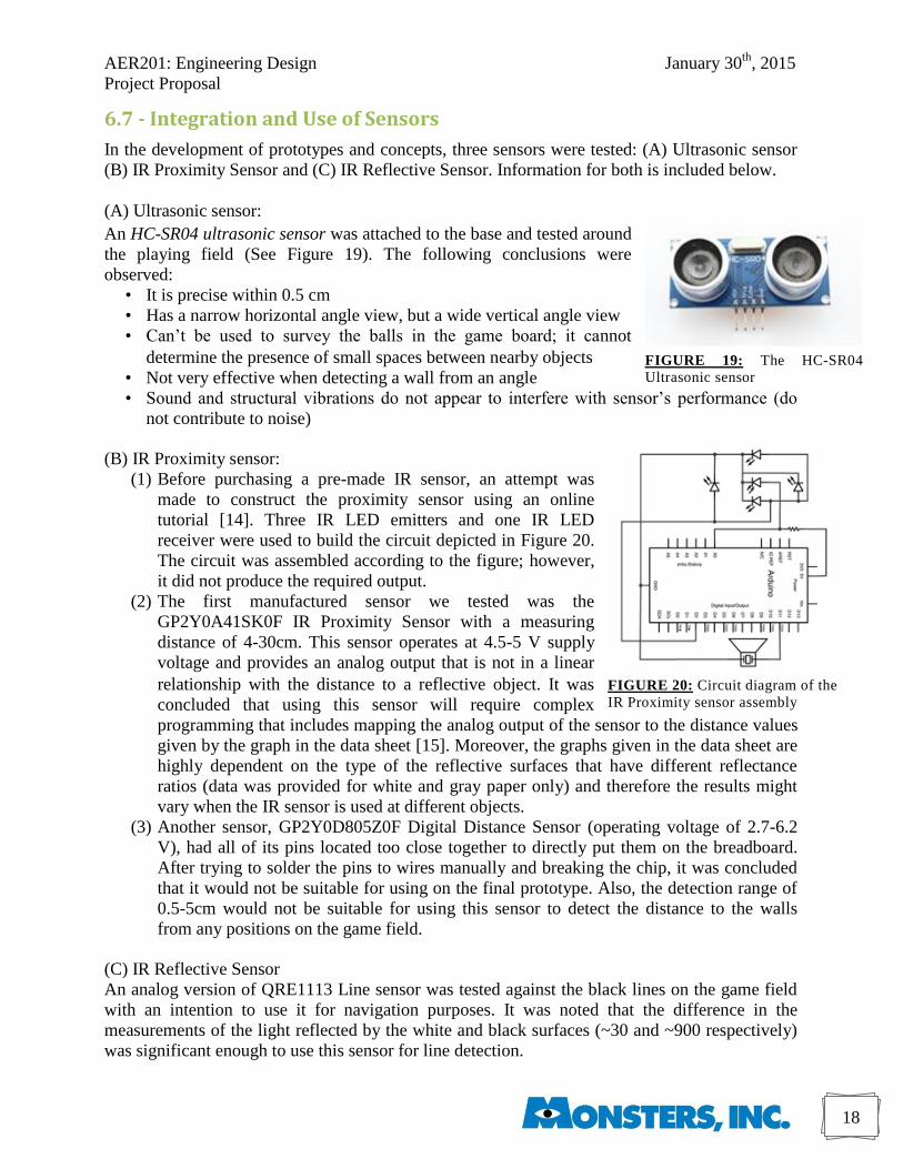
(4) The servo motor was also tested. A potentiometer was used to change the resistance of
the resistor used in the circuit, which in turn varied the immediate position of the motor
(see Figures 15 &16). Since the servo motor only rotates 180° and didn’t provide much
torque, it was immediately eliminated as an option for driving the wheels. However, it is
still a viable option for the rotating platform and/or the rotating gripper arm (Discussed
on page 15).
FIGURE 15: Controlling a servo motor with Arduino
AER201: Engineering Design January 30th
, 2015
Project Proposal
17
FIGURE 18: Schematics of a
Darlington transistor array
6.6 - Circuit Development
Through prototyping certain components and testing the circuitry involved, a few additional
circuit systems were needed. In particular, these are the H-bridge and the Darlington transistor
array.
(1) The H-Bridge used in testing the DC and bipolar stepper motors was a L293D Texas
Instruments product. It was required to enable bi-polar rotations at voltages from 4.5 V
to 36 V, providing driving currents of up to 600mA [12]. The diagram below represents
the structure of the H-bridge with all its pins. Pins labeled 1-4 (with arrows) are
designed to be connected to the input pins from the Arduino microcontroller, pins
labeled ‘M’ are the outputs to the motors. Pins 4-5 and 12-13 are supposed to be
connected to ground, while pins 1, 9 (enable inputs) and 16 (power to the chip) are
connected to 5V supplied by the microcontroller. The last pin, 8, is connected to an
external power supply for the motor, for example a battery that can take a maximum of
36V. [11] The table below provides a summary of the inputs required from the
microcontroller to obtain specified motor movements, which was used to program the
function of the motors.
(2) To run the unipolar stepper motor the ULN2001
Darlington transistor array was used for current
amplification purposes (see Figure 18). According to
the manual, the output current and voltage of this chip
is 500mA and 50V respectively [13]. The 6-wire
unipolar stepper motor that was used for prototyping
was connected to pins 1-4 (OUT), whereas pins 1-4
(IN) were connected to the microcontroller. The 2
common wires from the motor were connected to pin
9.
FIGURE 17: a) Left:
Diagram of an H-bridge
with all pins labelled
b) Right: Table
summarizing motor
behaviour through
controlling an H-bridge
AER201: Engineering Design January 30th
, 2015
Project Proposal
18
FIGURE 20: Circuit diagram of the
IR Proximity sensor assembly
FIGURE 19: The HC-SR04
Ultrasonic sensor
6.7 - Integration and Use of Sensors
In the development of prototypes and concepts, three sensors were tested: (A) Ultrasonic sensor
(B) IR Proximity Sensor and (C) IR Reflective Sensor. Information for both is included below.
(A) Ultrasonic sensor:
An HC-SR04 ultrasonic sensor was attached to the base and tested around
the playing field (See Figure 19). The following conclusions were
observed:
• It is precise within 0.5 cm
• Has a narrow horizontal angle view, but a wide vertical angle view
• Can’t be used to survey the balls in the game board; it cannot
determine the presence of small spaces between nearby objects
• Not very effective when detecting a wall from an angle
• Sound and structural vibrations do not appear to interfere with sensor’s performance (do
not contribute to noise)
(B) IR Proximity sensor:
(1) Before purchasing a pre-made IR sensor, an attempt was
made to construct the proximity sensor using an online
tutorial [14]. Three IR LED emitters and one IR LED
receiver were used to build the circuit depicted in Figure 20.
The circuit was assembled according to the figure; however,
it did not produce the required output.
(2) The first manufactured sensor we tested was the
GP2Y0A41SK0F IR Proximity Sensor with a measuring
distance of 4-30cm. This sensor operates at 4.5-5 V supply
voltage and provides an analog output that is not in a linear
relationship with the distance to a reflective object. It was
concluded that using this sensor will require complex
programming that includes mapping the analog output of the sensor to the distance values
given by the graph in the data sheet [15]. Moreover, the graphs given in the data sheet are
highly dependent on the type of the reflective surfaces that have different reflectance
ratios (data was provided for white and gray paper only) and therefore the results might
vary when the IR sensor is used at different objects.
(3) Another sensor, GP2Y0D805Z0F Digital Distance Sensor (operating voltage of 2.7-6.2
V), had all of its pins located too close together to directly put them on the breadboard.
After trying to solder the pins to wires manually and breaking the chip, it was concluded
that it would not be suitable for using on the final prototype. Also, the detection range of
0.5-5cm would not be suitable for using this sensor to detect the distance to the walls
from any positions on the game field.
(C) IR Reflective Sensor
An analog version of QRE1113 Line sensor was tested against the black lines on the game field
with an intention to use it for navigation purposes. It was noted that the difference in the
measurements of the light reflected by the white and black surfaces (~30 and ~900 respectively)
was significant enough to use this sensor for line detection.
AER201: Engineering Design January 30th
, 2015
Project Proposal
19
6.8 - Code structure
The first amalgamated code comprised of controlling two bi-directional DC motors that interact
with an ultrasonic sensor. The sections of the code are identified below.
Navigation:
The first prototype of the base was programmed to move using odometry (see Flowchart 1,
Appendix E). The margin of error of odometry was larger than expected, due to the variations in
voltage that was supplied to the motors. The robot may potentially deviate from its path and lose
track of its position often, thus requiring to reorient itself frequently which can take a
considerable amount of time. After this analysis, it was determined that this approach would not
be an effective method to reach the team’s goal of delivering most of the balls in 7 minutes.
Ultrasonic sensor:
The robot was sensing the distance of objects in front of it using an ultrasonic sensor. The sensor
gave accurate readings when the objects ahead were not at an angle. Programming the sensor was
simple, but the sensor gave occasional erroneous readings. Therefore a method for calculating the
averages between multiple readings was tried out to minimize the chances of processing faulty
information. The details for the method are given in Section 7.4.
IR proximity sensor:
The IR proximity sensor was tested to compare it to the ultrasonic sensor. The coding structure
for it is more complicated because the relation for mapping the voltage readings of the sensor to
the distance is not linear. It requires the use of lookup tables along with interpolation to calculate
the required distance. The readings from the IR sensor were less accurate than those from the
ultrasonic sensor.
7 - Specification of Proposed Design
The ideas outlined in Section 5 and the prototypes tested in Section 6 were analysed for their
ability to accomplish the team’s goals. The detailed comparisons between the different ideas and
prototypes along with the reasoning of choosing this proposed design are mentioned in Appendix
D. A brief introduction is given below for the proposed design, after which a detailed description
is given for each aspect of the design.
7.1 - Holistic Design
Primary Locomotion:
A main priority of the robot is speed: the robot should be fast and move easily between different
locations on the playing field. The base of the robot consists of two wheels each connected to a
DC motor for differential steering, and a ball caster to provide structural and locomotive support.
The wheels have a large diameter to increase the speed for a given motor rotation.
AER201: Engineering Design January 30th
, 2015
Project Proposal
20
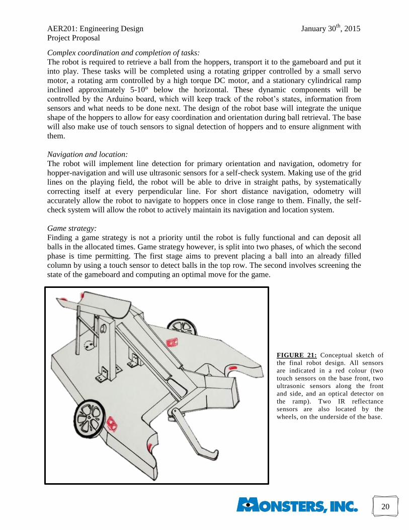
FIGURE 21: Conceptual sketch of
the final robot design. All sensors
are indicated in a red colour (two
touch sensors on the base front, two
ultrasonic sensors along the front
and side, and an optical detector on
the ramp). Two IR reflectance
sensors are also located by the
wheels, on the underside of the base.
Complex coordination and completion of tasks:
The robot is required to retrieve a ball from the hoppers, transport it to the gameboard and put it
into play. These tasks will be completed using a rotating gripper controlled by a small servo
motor, a rotating arm controlled by a high torque DC motor, and a stationary cylindrical ramp
inclined approximately 5-10° below the horizontal. These dynamic components will be
controlled by the Arduino board, which will keep track of the robot’s states, information from
sensors and what needs to be done next. The design of the robot base will integrate the unique
shape of the hoppers to allow for easy coordination and orientation during ball retrieval. The base
will also make use of touch sensors to signal detection of hoppers and to ensure alignment with
them.
Navigation and location:
The robot will implement line detection for primary orientation and navigation, odometry for
hopper-navigation and will use ultrasonic sensors for a self-check system. Making use of the grid
lines on the playing field, the robot will be able to drive in straight paths, by systematically
correcting itself at every perpendicular line. For short distance navigation, odometry will
accurately allow the robot to navigate to hoppers once in close range to them. Finally, the self-
check system will allow the robot to actively maintain its navigation and location system.
Game strategy:
Finding a game strategy is not a priority until the robot is fully functional and can deposit all
balls in the allocated times. Game strategy however, is split into two phases, of which the second
phase is time permitting. The first stage aims to prevent placing a ball into an already filled
column by using a touch sensor to detect balls in the top row. The second involves screening the
state of the gameboard and computing an optimal move for the game.
AER201: Engineering Design January 30th
, 2015
Project Proposal
21
7.2 - Electromechanical subsystem
Base: A two-wheeled direct drive system with differential steering will be implemented. Two bi-
directional 12-24V DC motors will be used. The third locomotive support is a ball caster, which
will also provide structural support and help reduce the load on the wheels. The wheels will have
a large diameter to increase the speed of the robot.
To maximize manoeuvrability, the robot should be small, so it won’t be obstructed by
obstacles when turning. However, an essential part of the navigation technique is to include the
shape of the hopper legs into the design of the base. In doing so, the robot will be able to align
with the hoppers for ball retrieval upon every approach, and any errors (to a certain tolerance)
will be automatically corrected by the design of the base. Thus, load is taken off the processing
system. To ensure proper alignment, touch sensors will be integrated into the curvature of the
hopper-fitting base, to tell the micro-processing unit when the robot is in position.
The base will be constructed of light wood so it is structurally stable. The single-piece
composition works to eliminate unnecessary mechanical complexity and potential points of
failure. Particle board (pressboard) will be avoided due to its weight and plywood due to grain
and composition variabilities. Balsa wood is an ideal material for the base, as it is both strong and
lightweight. Wheels will be made of plastic with rubber grips, and will connect to the shaft of the
motor using hubs to strengthen the fixture. Motors will then be mounted onto the base using
aluminum brackets. Hardware pieces including screws, washers and nuts will be used to fix
components onto the wooden board, allowing for easy removal if required.
Retriever: The robot will get the balls from the hopper using a specialized rotational gripper
consisting of three main components: a stationary holder, a moving finger, and an actuator. The
stationary holder will house the ball upon retrieval. The moving finger will remain low to the
ground, so it can move under the bristles at the hopper base and push the ball out and into the
stationary holder. The finger will hug the ball from the outer end, but will be large enough to
account for any variability in hopper design and to provide a large tolerance for any alignment
issues. This moving finger will be controlled by a small, lightweight and low torque servo motor.
The retriever will likely be made of lightweight wood (preferably balsa wood), thin
Plexiglas, and/or sheet metal. The various materials will be used in different components of the
retriever, such as the use of wood or Plexiglas for the body of the retriever and sheet metal for
any assembly requirements.
Lift and Release: The retriever will be connected to the bottom of a rotating arm, driven by a
high torque DC motor. The arm will be angled, and long enough to allow the ball to roll off the
arm and onto the ramp to be deposited into the gameboard. The arm will be relatively narrow –
approximately 6-10cm, to allow the ball to easily slide down.
The arm will be made of balsa wood or aluminum rails, to create an arm with a high
strength-to-weight ratio. A ‘frame’ approach instead of a ‘solid piece’ approach will work to
reduce the torque requirements on the driving motor. Weights may be added to the other end of
the arm, to help the motor complete the required rotation. The ramp will likely be made of
cardboard, strong enough to withstand any impact with the gameboard, but incredibly light so to
reduce load on the robot. Finally, the cardboard is smooth enough to allow the ball to roll down
easily. If it’s determined the ball is moving too fast down the ramp, small sections of sandpaper
or soft carpet material will be added to slow the ball down. The end of the ramp will be designed
so to best guide the ball into the desired column.
AER201: Engineering Design January 30th
, 2015
Project Proposal
22
7.3 - Circuit subsystem
Base: Due to the imposed constraint of not having any breadboards in the final design of the
robot, it was decided to use protoboards as the construction base for all circuitry needed in this
project. Protoboards are beneficial since they provide a semi-permanent assembly of all electrical
components and are a lot thinner and more robust than regular breadboards - this allows them to
be stackable. Breakout boards were eliminated as an option due to their high cost.
Sensors: To simplify the process of robot’s orientation near the hoppers, touch sensors in the
form of regular toggle switches will be included on the design of the base. The input from these
switches will check if both circle cut-outs have reached the hopper legs, and if not, the robot will
reorient itself. An additional touch sensor will be used to avoid overflowing the columns in the
gameboard by checking for the presence of a ball in the last row of the gameboard. After testing
different proximity sensors, two HC-SR04 ultrasonic sensors were selected to assist in
navigation, due to their accuracy in determining the distance to side walls. Two QRE1113 IR
reflectance sensors, proved to be effective at detecting the black grid lines on the playing field,
will be used for line detection. Also, one optical detector will be used on the release ramp
mechanism, which will check that the ball has been deposited into the game board. As soon as
the ping pong ball passes the detector, a signal will be sent to the microcontroller to inform it that
the robot is ready to go pick up another ball.
7.4 - Microcontroller subsystem
Microcontroller: The microcontroller used is Arduino Mega, due to the number of pins needed.
The chart for the needed pins is outlines in Appendix F.
Navigation: The playing field is divided into 72 squares of 20cm x 20cm (9 by 8 grid), which the
robot will use for locating itself. The position of the sensors will be logged into a data array and
updated as the robot crosses from one square to another. The robot will use the grid lines on the
playing field for line detection. Two IR reflectance sensors will be used to orient the robot by
detecting the perpendicular lines to the direction of motion of the robot. Suppose the left sensor
reaches the perpendicular line before the right sensor. This will cause the left wheel to stop
turning, until the right sensor reaches the line. This method will allow the robot to reorient itself
frequently, without losing time to do so. All the turns of the robot would be 90° turns, so the
robot is constantly parallel to a set of lines and is perpendicular to the other set.
To get more information about its position, the robot will use two ultrasonic sensors: one
facing the front and one facing the side. When the robot is near a wall, the sensors will read the
distance to the walls, crosscheck this with the position in the robot’s log, and fix it if necessary.
Since the hoppers can have different orientations in the field, reaching the hoppers with
the navigation system above may be difficult. Thus, odometry will be implemented to help the
robot reach the hoppers. The robot will navigate to a region (or square) with a hopper (hopper
positions will be pre-programmed into the robot’s memory within the 3-minute setup window),
then use odometry to reach the hopper and orient itself for ball retrieval. Optical encoders will
calculate the rotations of the motor’s shaft to be used in odometry calculations rather than the
time in order to account for the slight variations of voltage supplied by the batteries. Using
odometry for small distances will minimize accumulation of errors. Refer to Flowchart 2 in
Appendix E for a draft of this code.
AER201: Engineering Design January 30th
, 2015
Project Proposal
23
Filtering Noise and Inaccurate Sensor Readings: The position of the robot will be verified using
two ultrasonic sensors. One sensor will be placed facing the front and the other facing the side of
the robot. Inaccurate sensor readings may cause data spikes, which consist of data readings that
are very small or very large. In order to minimize the risk of inaccurate readings, a filtering
method will be implemented. It is important to note that this is not a common occurrence, and the
filtering is simply a safety and reliability measure. The filtering method will take in seven
consecutive data readings, arranges them in ascending order and calculates their average. If the
average deviates from the median of the data by 1 cm, the data is trimmed - two values are
eliminated from each end of the data set - and the average is recalculated. The trimmed average is
used to make decisions in other operations with an imposed minimum threshold of a distance of
0.5 cm in order to prevent erroneous small readings.
Hoppers: The placements of the hoppers will be entered into the Arduino using pushbuttons, and
the input will be verified by an LCD display, with the option to re-enter the data if an error has
been made. The robot will depend on these predefined coordinates of the hoppers when
navigating the playing field.
Game board: There are two phases to game strategy, which are discussed below.
Phase 1: The state of the gameboard will be tested in order to place balls. A touch sensor will be
used to determine if there is a vacancy in the top row of the column of interest. If a ball is there,
the robot stores this into its memory, and then moves to another column. Upon re-approach to the
gameboard, the robot will check its memory, thus knowing which columns are filled.
Phase 2: The robot will use a camera to scan the state of the gameboard and calculate an optimal
placement of the balls in order to increase the number of connect 4s and block the opponent’s
formations.
8 - Project Management
8.1 - Timeline and project plan
A Gantt chart (see Appendix G) is used to outline the timeline of the project. The progress
evaluations are marked to provide markers for completing the required components. Each task is
given more time that it should need in order to account for any problems or complications that
come up during the progress of the project. The main milestones set are the three progress
evaluations, the preliminary competition and the design competition.
Progress Evaluation I: A functional base will act as the integrated component for this evaluation.
It will be able to move, detect objects nearby and react as required.
Progress Evaluation II: The ball retriever will be functional and housed onto the completed base.
The robot will be able to navigate the gameboard using the line detection technique outlines in
Section 7.4. It will be able to locate the hoppers by accepting their locations from the user and
retrieve balls from them.
Progress Evaluation III: The robot will be fully functional and capable of playing the 7-minute
long game. It will be able to complete all the tasks outlined for this evaluation. The focus will be
shifted to ensure robustness and reliability of the robot, and to optimize its performance.
AER201: Engineering Design January 30th
, 2015
Project Proposal
24
8.2 - Division of labour
The division of tasks is outlined in the Gantt chart for each subsystem. Each member of the team
is responsible for completing the tasks assigned to their respective subsystem and to ensure that it
is compatible with other subsystems. In order to accomplish this, team discussions are held
frequently in order to unify the vision of the project and update the plan and the designs as the
robot progresses.
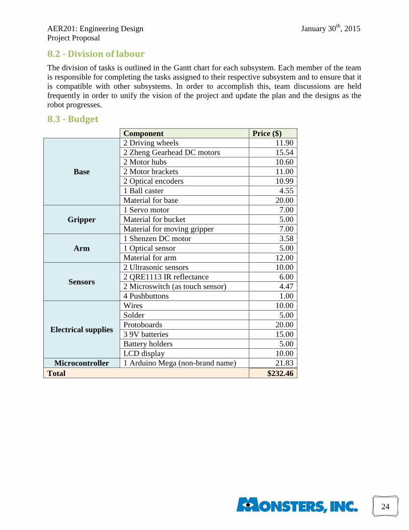
8.3 - Budget
Component Price ($)
Base
2 Driving wheels 11.90
2 Zheng Gearhead DC motors 15.54
2 Motor hubs 10.60
2 Motor brackets 11.00
2 Optical encoders 10.99
1 Ball caster 4.55
Material for base 20.00
Gripper
1 Servo motor 7.00
Material for bucket 5.00
Material for moving gripper 7.00
Arm
1 Shenzen DC motor 3.58
1 Optical sensor 5.00
Material for arm 12.00
Sensors
2 Ultrasonic sensors 10.00
2 QRE1113 IR reflectance 6.00
2 Microswitch (as touch sensor) 4.47
4 Pushbuttons 1.00
Electrical supplies
Wires 10.00
Solder 5.00
Protoboards 20.00
3 9V batteries 15.00
Battery holders 5.00
LCD display 10.00
Microcontroller 1 Arduino Mega (non-brand name) 21.83
Total $232.46
AER201: Engineering Design January 30th
, 2015
Project Proposal
25
9 - Conclusion
The design proposed by Monsters, Inc. was a result of careful analysis based on careful
examination of conceptual ideas and analysis of prototypes. The proposed design of the project
aims to have a high degree of error tolerance without compromising the effectiveness and speed
of the robot.
These goals are accomplished by using two-wheel direct drive to minimize the slippage,
implementing a rotating gripper to allow for some freedom while retrieving the ball,
implementing a rotating arm to elevate the ball quickly, moulding the base into the shape of the
hoppers to align easily and using three different navigation techniques to optimize performance.
The proposed design encompasses techniques and ideas that combine the best attributes
of each of the concept ideas. It was a result of a series of brainstorming, converging, testing and
iterating designs in order to ensure it meets the outlined goals in an effective manner.
No matter how meticulous the planning, complications will still arise. Understanding this
is critical to dealing with them and coming up with solutions. The planning of the project does
involve room for troubleshooting, fixing problems and perfecting the designs. Expecting the
problems beforehand alleviates stress from the members of a team, allowing them to come up
with creative solutions.
Monsters, Inc. believes that effective team collaboration, combined with persistence and a
motivation to excel, will result in great outcomes. Gathering the right resources is important to
success, but work attitude and effectiveness can make a big different to any project, especially
one with a constricted timeline and limited budget. Monsters, Inc. combines competent
engineering designs with positive work attitudes to reach the expected goals and exceed
expectations. Just sit back and watch.
AER201: Engineering Design January 30th
, 2015
Project Proposal
26
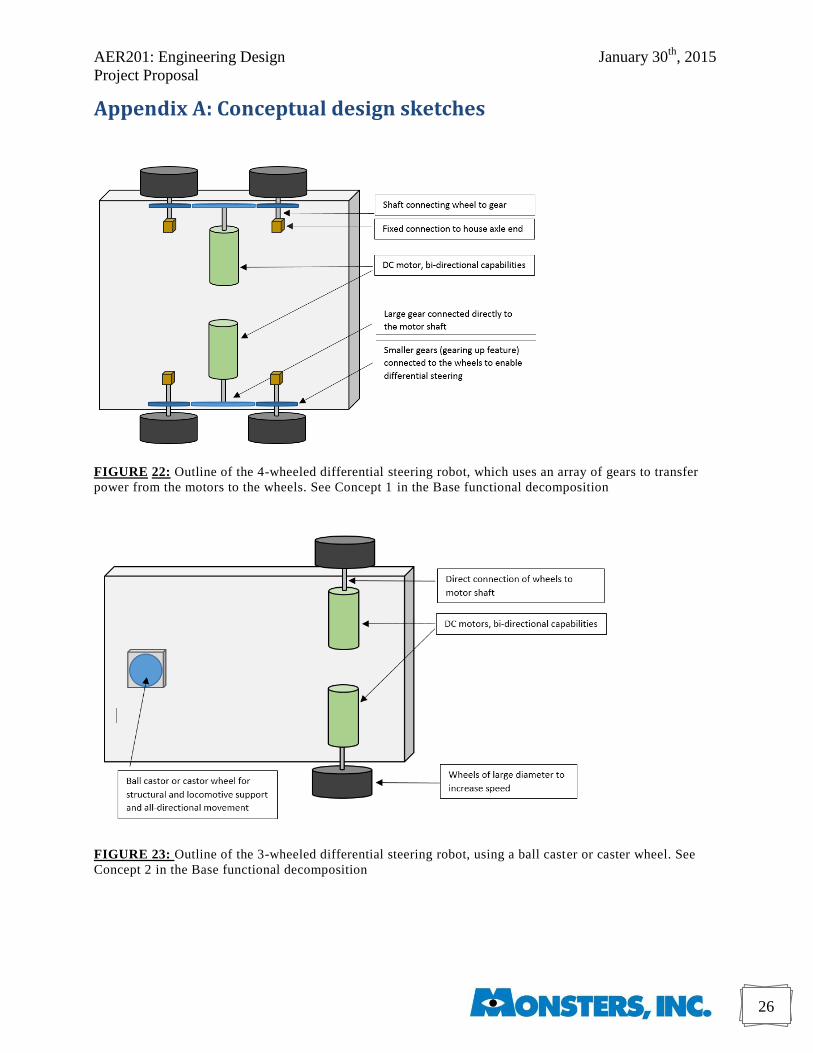
Appendix A: Conceptual design sketches
FIGURE 22: Outline of the 4-wheeled differential steering robot, which uses an array of gears to transfer
power from the motors to the wheels. See Concept 1 in the Base functional decomposition
FIGURE 23: Outline of the 3-wheeled differential steering robot, using a ball caster or caster wheel. See
Concept 2 in the Base functional decomposition
AER201: Engineering Design January 30th
, 2015
Project Proposal
27
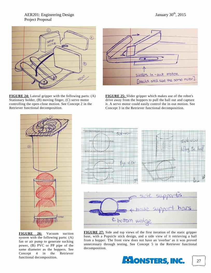
FIGURE 26: Vacuum suction
system with the following parts: (A)
fan or air pump to generate sucking
power, (B) PVC or PP pipe of the
same diameter as the hoppers. See
Concept 4 in the Retriever
functional decomposition.
FIGURE 27: Side and top views of the first iteration of the static gripper
base, with a Popsicle stick design, and a side view of it retrieving a ball
from a hopper. The front view does not have an 'overbar' as it was proved
unnecessary through testing. See Concept 5 in the Retriever functional
decomposition.
FIGURE 24: Lateral gripper with the following parts: (A)
Stationary holder, (B) moving finger, (C) servo motor
controlling the open-close motion. See Concept 2 in the
Retriever functional decomposition.
FIGURE 25: Slider gripper which makes use of the robot's
drive away from the hoppers to pull the ball out and capture
it. A servo motor could easily control the in-out motion. See
Concept 3 in the Retriever functional decomposition.
AER201: Engineering Design January 30th
, 2015
Project Proposal
28
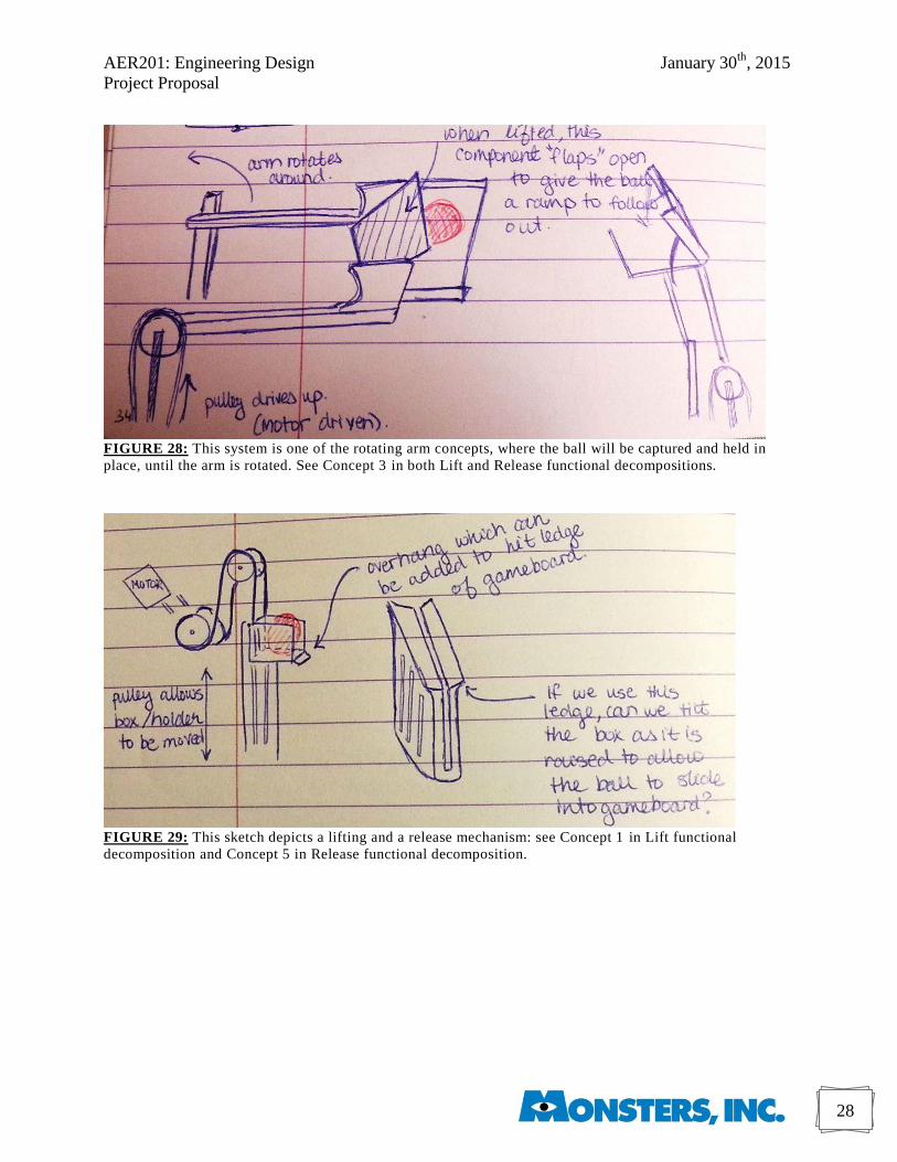
FIGURE 28: This system is one of the rotating arm concepts, where the ball will be captured and held in
place, until the arm is rotated. See Concept 3 in both Lift and Release functional decompositions.
FIGURE 29: This sketch depicts a lifting and a release mechanism: see Concept 1 in Lift functional
decomposition and Concept 5 in Release functional decomposition.
AER201: Engineering Design January 30th
, 2015
Project Proposal
29
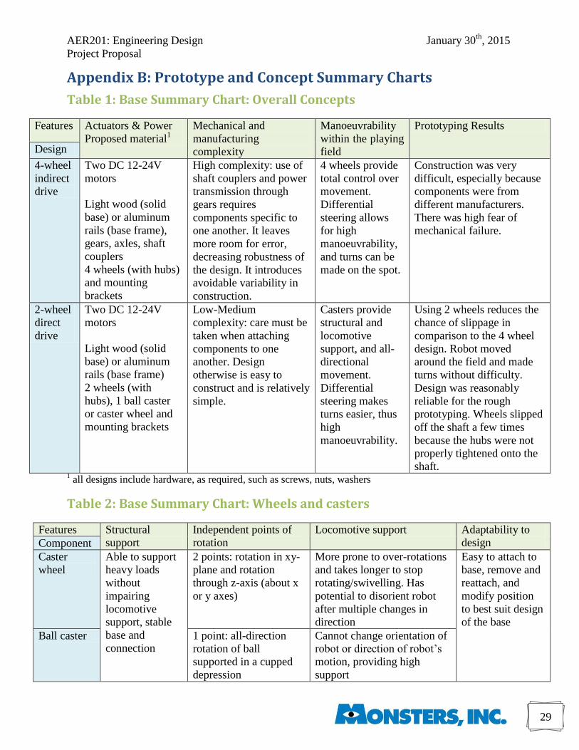
Appendix B: Prototype and Concept Summary Charts
Table 1: Base Summary Chart: Overall Concepts
Features Actuators & Power
Proposed material1
Mechanical and
manufacturing
complexity
Manoeuvrability
within the playing
field
Prototyping Results
Design
4-wheel
indirect
drive
Two DC 12-24V
motors
Light wood (solid
base) or aluminum
rails (base frame),
gears, axles, shaft
couplers
4 wheels (with hubs)
and mounting
brackets
High complexity: use of
shaft couplers and power
transmission through
gears requires
components specific to
one another. It leaves
more room for error,
decreasing robustness of
the design. It introduces
avoidable variability in
construction.
4 wheels provide
total control over
movement.
Differential
steering allows
for high
manoeuvrability,
and turns can be
made on the spot.
Construction was very
difficult, especially because
components were from
different manufacturers.
There was high fear of
mechanical failure.
2-wheel
direct
drive
Two DC 12-24V
motors
Light wood (solid
base) or aluminum
rails (base frame)
2 wheels (with
hubs), 1 ball caster
or caster wheel and
mounting brackets
Low-Medium
complexity: care must be
taken when attaching
components to one
another. Design
otherwise is easy to
construct and is relatively
simple.
Casters provide
structural and
locomotive
support, and all-
directional
movement.
Differential
steering makes
turns easier, thus
high
manoeuvrability.
Using 2 wheels reduces the
chance of slippage in
comparison to the 4 wheel
design. Robot moved
around the field and made
turns without difficulty.
Design was reasonably
reliable for the rough
prototyping. Wheels slipped
off the shaft a few times
because the hubs were not
properly tightened onto the
shaft. 1 all designs include hardware, as required, such as screws, nuts, washers
Table 2: Base Summary Chart: Wheels and casters
Features Structural
support
Independent points of
rotation
Locomotive support Adaptability to
design Component
Caster
wheel
Able to support
heavy loads
without
impairing
locomotive
support, stable
base and
connection
2 points: rotation in xy-
plane and rotation
through z-axis (about x
or y axes)
More prone to over-rotations
and takes longer to stop
rotating/swivelling. Has
potential to disorient robot
after multiple changes in
direction
Easy to attach to
base, remove and
reattach, and
modify position
to best suit design
of the base
Ball caster 1 point: all-direction
rotation of ball
supported in a cupped
depression
Cannot change orientation of
robot or direction of robot’s
motion, providing high
support
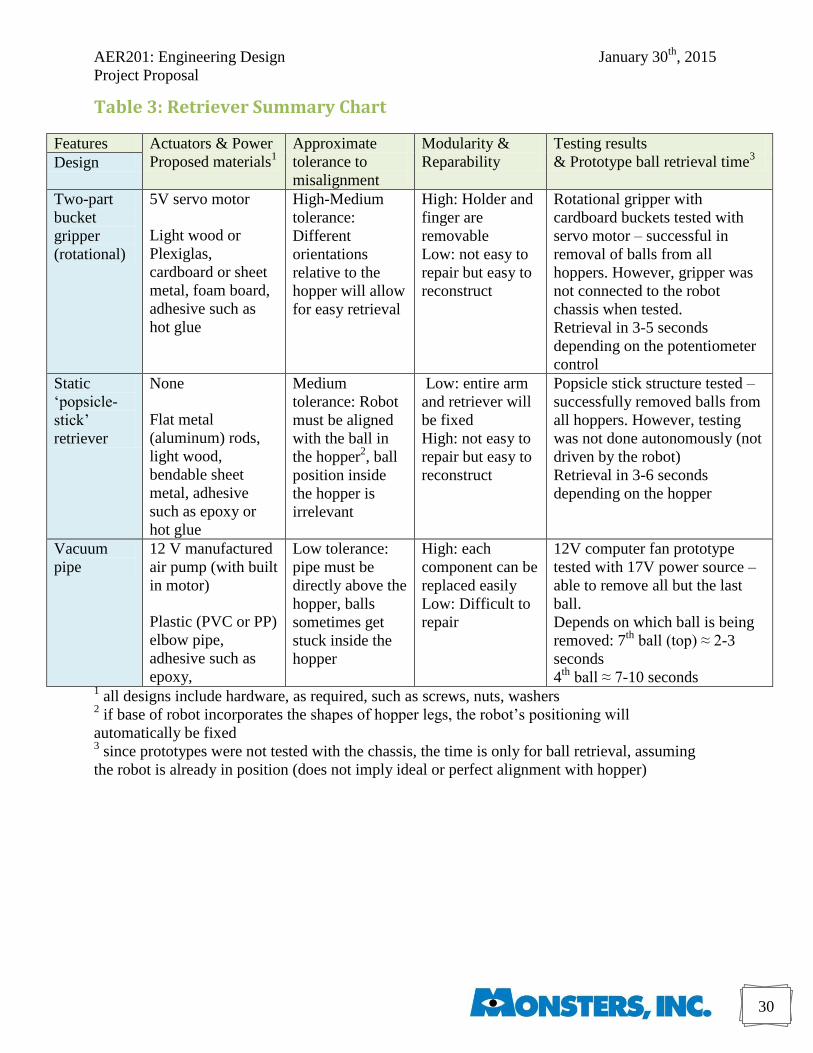
AER201: Engineering Design January 30th
, 2015
Project Proposal
30
Table 3: Retriever Summary Chart
Features Actuators & Power
Proposed materials1
Approximate
tolerance to
misalignment
Modularity &
Reparability
Testing results
& Prototype ball retrieval time3 Design
Two-part
bucket
gripper
(rotational)
5V servo motor
Light wood or
Plexiglas,
cardboard or sheet
metal, foam board,
adhesive such as
hot glue
High-Medium
tolerance:
Different
orientations
relative to the
hopper will allow
for easy retrieval
High: Holder and
finger are
removable
Low: not easy to
repair but easy to
reconstruct
Rotational gripper with
cardboard buckets tested with
servo motor – successful in
removal of balls from all
hoppers. However, gripper was
not connected to the robot
chassis when tested.
Retrieval in 3-5 seconds
depending on the potentiometer
control
Static
‘popsicle-
stick’
retriever
None
Flat metal
(aluminum) rods,
light wood,
bendable sheet
metal, adhesive
such as epoxy or
hot glue
Medium
tolerance: Robot
must be aligned
with the ball in
the hopper2, ball
position inside
the hopper is
irrelevant
Low: entire arm
and retriever will
be fixed
High: not easy to
repair but easy to
reconstruct
Popsicle stick structure tested –
successfully removed balls from
all hoppers. However, testing
was not done autonomously (not
driven by the robot)
Retrieval in 3-6 seconds
depending on the hopper
Vacuum
pipe
12 V manufactured
air pump (with built
in motor)
Plastic (PVC or PP)
elbow pipe,
adhesive such as
epoxy,
Low tolerance:
pipe must be
directly above the
hopper, balls
sometimes get
stuck inside the
hopper
High: each
component can be
replaced easily
Low: Difficult to
repair
12V computer fan prototype
tested with 17V power source –
able to remove all but the last
ball.
Depends on which ball is being
removed: 7th
ball (top) ≈ 2-3
seconds
4th
ball ≈ 7-10 seconds 1 all designs include hardware, as required, such as screws, nuts, washers
2 if base of robot incorporates the shapes of hopper legs, the robot’s positioning will
automatically be fixed 3 since prototypes were not tested with the chassis, the time is only for ball retrieval, assuming
the robot is already in position (does not imply ideal or perfect alignment with hopper)
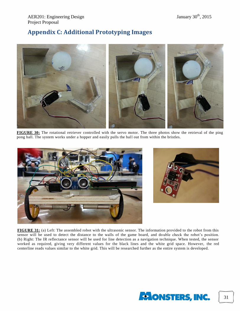
AER201: Engineering Design January 30th
, 2015
Project Proposal
31
FIGURE 30: The rotational retriever controlled with the servo motor. The three photos show the retrieval of the ping
pong ball. The system works under a hopper and easily pulls the bal l out from within the bristles.
FIGURE 31: (a) Left: The assembled robot with the ultrasonic sensor. The information provided to the robot from this
sensor will be used to detect the distance to the walls of the game board, and do uble check the robot’s position.
(b) Right: The IR reflectance sensor will be used for line detection as a navigation technique. When tested, the sensor
worked as required, giving very different values for the black lines and the white grid space. However, the red
centerline reads values similar to the white grid. This will be researched further as the entire system is developed.
Appendix C: Additional Prototyping Images
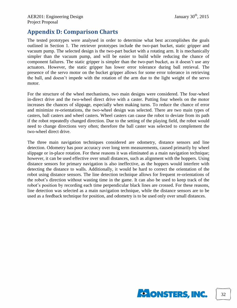
AER201: Engineering Design January 30th
, 2015
Project Proposal
32
Appendix D: Comparison Charts
The tested prototypes were analysed in order to determine what best accomplishes the goals
outlined in Section 1. The retriever prototypes include the two-part bucket, static gripper and
vacuum pump. The selected design is the two-part bucket with a rotating arm. It is mechanically
simpler than the vacuum pump, and will be easier to build while reducing the chance of
component failures. The static gripper is simpler than the two-part bucket, as it doesn’t use any
actuators. However, the static gripper has lower error tolerance during ball retrieval. The
presence of the servo motor on the bucket gripper allows for some error tolerance in retrieving
the ball, and doesn’t impede with the rotation of the arm due to the light weight of the servo
motor.
For the structure of the wheel mechanisms, two main designs were considered. The four-wheel
in-direct drive and the two-wheel direct drive with a caster. Putting four wheels on the motor
increases the chances of slippage, especially when making turns. To reduce the chance of error
and minimize re-orientations, the two-wheel design was selected. There are two main types of
casters, ball casters and wheel casters. Wheel casters can cause the robot to deviate from its path
if the robot repeatedly changed direction. Due to the setting of the playing field, the robot would
need to change directions very often; therefore the ball caster was selected to complement the
two-wheel direct drive.
The three main navigation techniques considered are odometry, distance sensors and line
detection. Odometry has poor accuracy over long term measurements, caused primarily by wheel
slippage or in-place rotation. For these reasons it was eliminated as a main navigation technique;
however, it can be used effective over small distances, such as alignment with the hoppers. Using
distance sensors for primary navigation is also ineffective, as the hoppers would interfere with
detecting the distance to walls. Additionally, it would be hard to correct the orientation of the
robot using distance sensors. The line detection technique allows for frequent re-orientations of
the robot’s direction without wasting time in the game. It can also be used to keep track of the
robot’s position by recording each time perpendicular black lines are crossed. For these reasons,
line detection was selected as a main navigation technique, while the distance sensors are to be
used as a feedback technique for position, and odometry is to be used only over small distances.
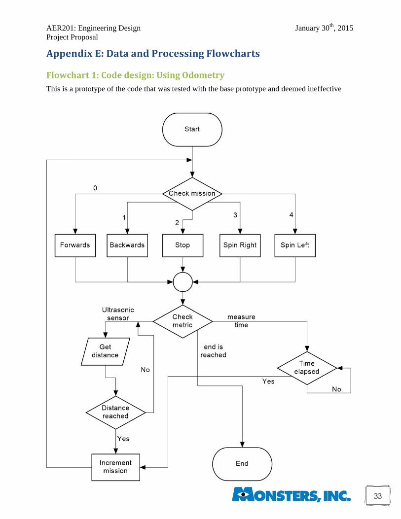
AER201: Engineering Design January 30th
, 2015
Project Proposal
33
Appendix E: Data and Processing Flowcharts
Flowchart 1: Code design: Using Odometry
This is a prototype of the code that was tested with the base prototype and deemed ineffective
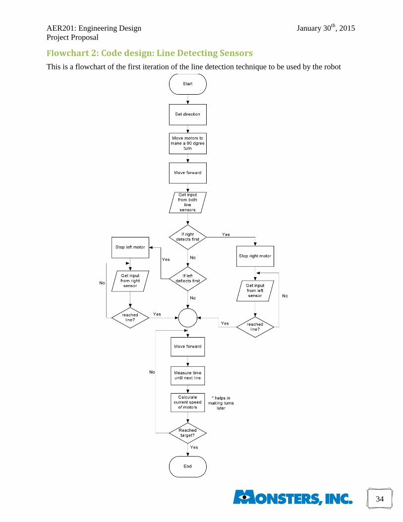
AER201: Engineering Design January 30th
, 2015
Project Proposal
34
Flowchart 2: Code design: Line Detecting Sensors
This is a flowchart of the first iteration of the line detection technique to be used by the robot
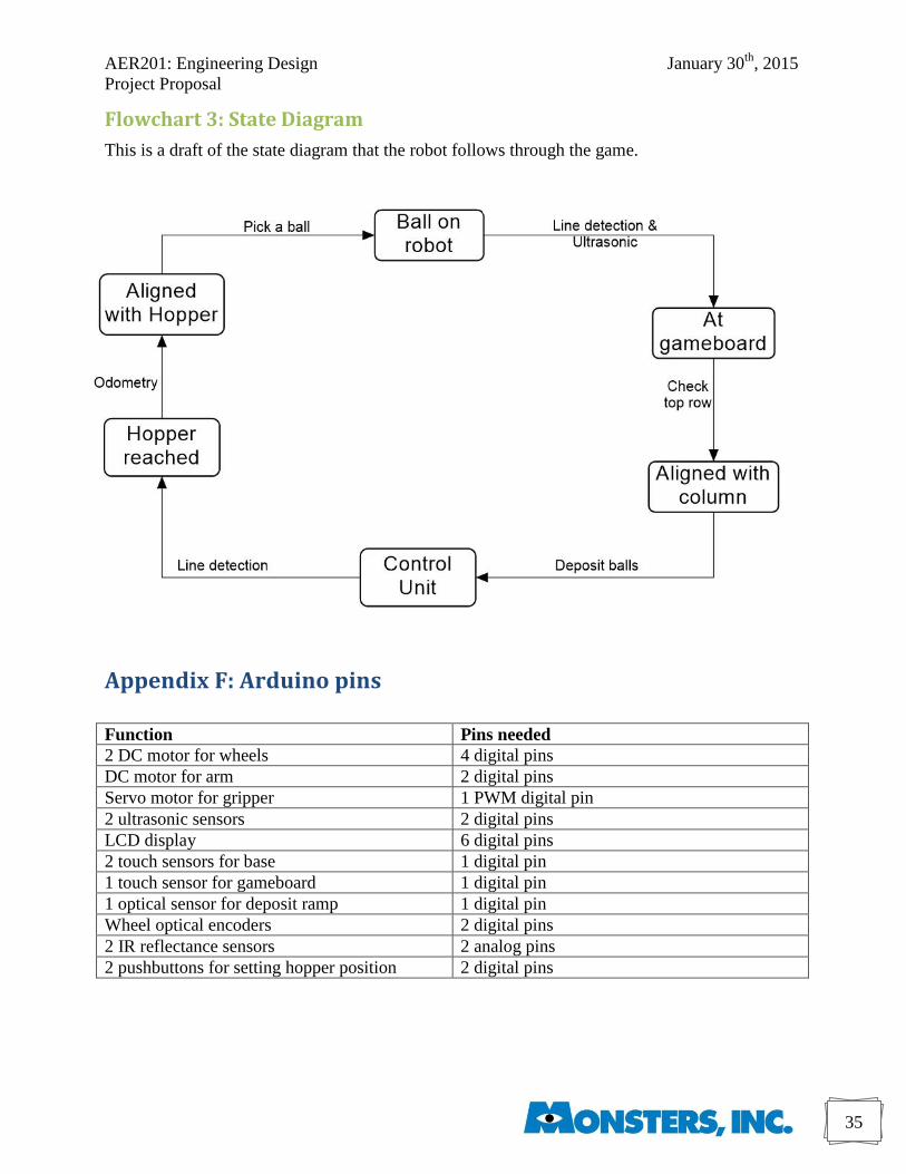
AER201: Engineering Design January 30th
, 2015
Project Proposal
35
Flowchart 3: State Diagram
This is a draft of the state diagram that the robot follows through the game.
Appendix F: Arduino pins
Function Pins needed
2 DC motor for wheels 4 digital pins
DC motor for arm 2 digital pins
Servo motor for gripper 1 PWM digital pin
2 ultrasonic sensors 2 digital pins
LCD display 6 digital pins
2 touch sensors for base 1 digital pin
1 touch sensor for gameboard 1 digital pin
1 optical sensor for deposit ramp 1 digital pin
Wheel optical encoders 2 digital pins
2 IR reflectance sensors 2 analog pins
2 pushbuttons for setting hopper position 2 digital pins
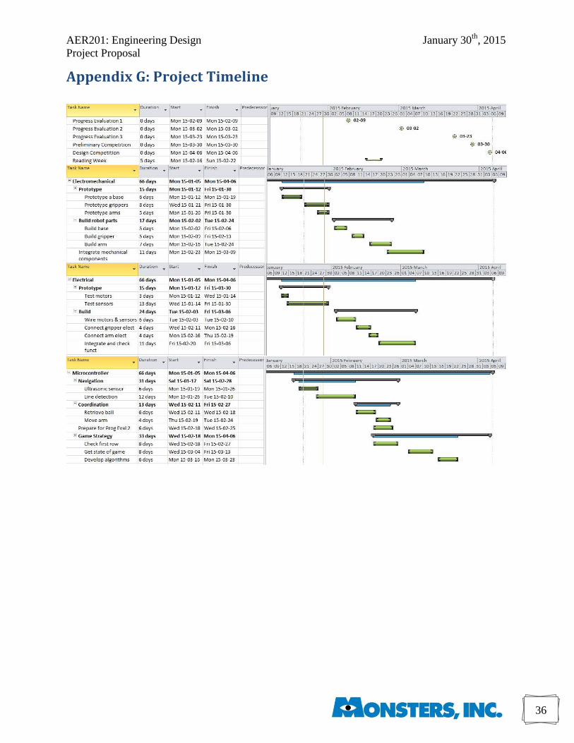
AER201: Engineering Design January 30th
, 2015
Project Proposal
36
Appendix G: Project Timeline
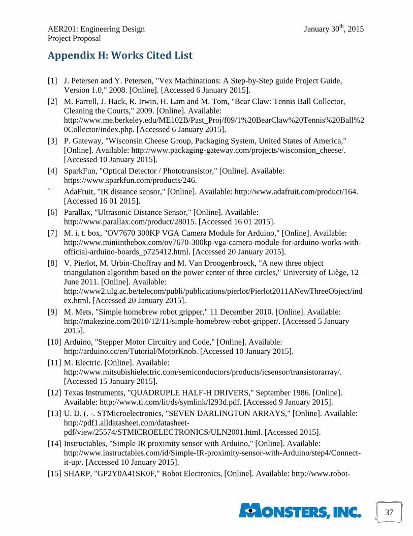
AER201: Engineering Design January 30th
, 2015
Project Proposal
37
Appendix H: Works Cited List
[1] J. Petersen and Y. Petersen, "Vex Machinations: A Step-by-Step guide Project Guide,
Version 1.0," 2008. [Online]. [Accessed 6 January 2015].
[2] M. Farrell, J. Hack, R. Irwin, H. Lam and M. Tom, "Bear Claw: Tennis Ball Collector,
Cleaning the Courts," 2009. [Online]. Available:
http://www.me.berkeley.edu/ME102B/Past_Proj/f09/1%20BearClaw%20Tennis%20Ball%2
0Collector/index.php. [Accessed 6 January 2015].
[3] P. Gateway, "Wisconsin Cheese Group, Packaging System, United States of America,"
[Online]. Available: http://www.packaging-gateway.com/projects/wisconsion_cheese/.
[Accessed 10 January 2015].
[4] SparkFun, "Optical Detector / Phototransistor," [Online]. Available:
https://www.sparkfun.com/products/246.
` AdaFruit, "IR distance sensor," [Online]. Available: http://www.adafruit.com/product/164.
[Accessed 16 01 2015].
[6] Parallax, "Ultrasonic Distance Sensor," [Online]. Available:
http://www.parallax.com/product/28015. [Accessed 16 01 2015].
[7] M. i. t. box, "OV7670 300KP VGA Camera Module for Arduino," [Online]. Available:
http://www.miniinthebox.com/ov7670-300kp-vga-camera-module-for-arduino-works-with-
official-arduino-boards_p725412.html. [Accessed 20 January 2015].
[8] V. Pierlot, M. Urbin-Choffray and M. Van Droogenbroeck, "A new three object
triangulation algorithm based on the power center of three circles," University of Liège, 12
June 2011. [Online]. Available:
http://www2.ulg.ac.be/telecom/publi/publications/pierlot/Pierlot2011ANewThreeObject/ind
ex.html. [Accessed 20 January 2015].
[9] M. Mets, "Simple homebrew robot gripper," 11 December 2010. [Online]. Available:
http://makezine.com/2010/12/11/simple-homebrew-robot-gripper/. [Accessed 5 January
2015].
[10] Arduino, "Stepper Motor Circuitry and Code," [Online]. Available:
http://arduino.cc/en/Tutorial/MotorKnob. [Accessed 10 January 2015].
[11] M. Electric. [Online]. Available:
http://www.mitsubishielectric.com/semiconductors/products/icsensor/transistorarray/.
[Accessed 15 January 2015].
[12] Texas Instruments, "QUADRUPLE HALF-H DRIVERS," September 1986. [Online].
Available: http://www.ti.com/lit/ds/symlink/l293d.pdf. [Accessed 9 January 2015].
[13] U. D. (. -. STMicroelectronics, "SEVEN DARLINGTON ARRAYS," [Online]. Available:
http://pdf1.alldatasheet.com/datasheet-
pdf/view/25574/STMICROELECTRONICS/ULN2001.html. [Accessed 2015].
[14] Instructables, "Simple IR proximity sensor with Arduino," [Online]. Available:
http://www.instructables.com/id/Simple-IR-proximity-sensor-with-Arduino/step4/Connect-
it-up/. [Accessed 10 January 2015].
[15] SHARP, "GP2Y0A41SK0F," Robot Electronics, [Online]. Available: http://www.robot-
AER201: Engineering Design January 30th
, 2015
Project Proposal
38
electronics.co.uk/datasheets/gp2y0a41sk_e.pdf. [Accessed 20 January 2015].
[16] E. Forkosh, "Infrared vs. Ultrasonic - What You Should Know," Society Of Robotics, 27
January 2008. [Online]. Available:
http://www.societyofrobots.com/member_tutorials/node/71. [Accessed 11 January 2015].
[17] A. O. Source, "Servo Motors," [Online]. Available: http://arduino.cc/en/Tutorial/sweep.
[Accessed 18 Jan 2015].
[18] C. Sipe, "HR Cinema: Monsters, Inc.," The Employer's Lawyer, 12 May 2014. [Online].
Available: http://employers-lawyer.com/hr-cinema/341/. [Accessed 25 January 2015].
[19] Halton District School Board, [Online]. Available:
http://chatt.hdsb.ca/~komljenovicm/snc%201d%20triangulation.htm. [Accessed 26 January
2015].
[20]
0
Disney Wikia, "Randall Boggs/Gallery," [Online]. Available:
http://img1.wikia.nocookie.net/__cb20131112044706/disney/images/2/26/Randall_''Randy''
_Boggs.png. [Accessed 30 January 2015].