SHOROC Bus Rapid Transit proposal - NSW Transport Infrastructure Summit October 2011

1
PROPOSAL FOR TRANSPORT OF HIGH‐WIDE LOADS
BONNER, MONTANA TO PORT OF ENTRY – SWEETGRASS, MONTANA
Prepared by:
Poteet Construction, Inc
9435 Summit Drive
Missoula, MT
59808
406.728.9370

2
TABLE OF CONTENTS
Section 1: Summary and Purpose of Proposal 3‐4
Section 2: Proposed Route 5‐15
Section 3: Traffic Control Overview 16‐22
Section 4: Traffic Control Detail, Rural Communities 23‐31
Section 5: Stop‐over/Emergency Parking 32‐33
Section 6: Emergency Response Plans 34‐37
Appendix A: Typical Stopover/Emergency Turnout Photos 38‐40
Appendix B: Traffic Count Data 41‐47
Appendix C: Load and Transport Equipment Details 48‐50
Appendix D: Utility Conflict Mitigation 41‐57
Appendix E: Proposal for Environmental Review 58‐63

3
SECTION 1: SUMMARY AND PURPOSE
The purpose of this document is to provide a plan for the transport of high and wide loads manufactured in Bonner, Montana to the Port of Entry ‐ Sweetgrass, Montana.
The dimensions of the loads specific to this document are approximately 24’ wide, 24’ high and 80’ long. The weight will be approximately 280 US tons. These dimensions and weights do not include the pull/push vehicle and trailer. The total loaded height is expected to be approximately 27’ to 29’. The loaded length, including pull vehicle, will be approximately 140’. These dimensions are large enough to necessitate travel on roadways free of permanent overhead obstructions (i.e., overpasses). Interstate highways are not considered in this proposal due to the presence of permanent overhead structures too low to permit passage of proposed load heights. Loads less than 14’ wide do not require special traffic control considerations and will not be addressed in this document.
NOTE: The dimensions described above are descriptive of typical loads that have been discussed in the planning phase and may vary widely according to manufacturing demands for products. Several higher and longer loads (up to 30’ high and 280’ long) have been successfully maneuvered on the proposed route. At which time production begins at the Bonner manufacturing site and specific weights and dimensions are known, the transport company will apply for a 32J permit from the Montana Department of Transportation (MDT). Final load dimensions and transport configurations will be determined and outlined for each type of load in conjunction with permit applications.
Included in this document:
Travel routes
Traffic management plans
Travel times
Traffic count data
Load and transport equipment descriptions
Overhead utility conflicts and solutions
Emergency response plans and contact information
Due to the anticipated frequency and dimensions of these loads, travel will occur between the hours of 10 p.m. and 6 a.m. MDT traffic count data shows that traffic volumes will be at their lowest during these hours, reducing conflicts with commuting and traveling public and school buses. Loads will travel only from Sunday night through Thursday night to avoid conflicts with weekend travel. Operations will be suspended for holidays and special community events as needed (rodeos, fairs, etc). This operation is anticipated to continue year‐round, weather permitting. Regular scheduling of loads will depend on manufacturing and travel logistics. Assuming that overhead utility conflicts have been mitigated prior to the final travel plans being submitted, it is projected that most loads, under good weather and road conditions, will complete the route in two nights.
Poteet Construction Inc. (PCI), of Missoula, Montana has been retained to outline this proposal by virtue of their experience in planning for and effecting the movement of high and wide loads along the

4
proposed route in a safe and efficient manner with minimum impact to residents, communities and the travelling public. PCI has been incorporated since 1987 and has provided traffic control services for private, state and federal highway projects throughout Montana and surrounding states. PCI will provide all traffic control devices and personnel for all load moves associated with this proposal.
Sarens Group, a world‐wide leader in heavy load lifting and transport, will be the contracted transport company. Sarens currently has a branch office in Missoula and has provided their expertise in moving oversized loads to the preparation of this proposal. Typical drawings of proposed loads and transport equipment are provided in Appendix C of this document.
5
SECTION 2: PROPOSED ROUTE
The proposed route lies entirely within Montana and consists of U.S. and State highways and secondary
roads from the manufacturing point in Bonner, Montana, to the Port of Entry‐Sweetgrass, Montana, on
the Canadian border. The proposed route is free from permanent overhead structures and has been
used for the transport of high and wide oversized loads since 2011.
The route is described as follows:
Montana State Highway 200 from Bonner to Bowman’s Corner (110.0 miles).
U.S. Highway 287 from Bowman’s Corner to Choteau (44.7 miles).
U.S. Highway 89 from Choteau to its junction with Montana Highway 44 just north of Dupuyer
(42.7 miles).
Montana Highway 44 to Valier (13.9 miles).
Montana Secondary Road 358 from Valier to its junction with U.S. Highway 2 in Cut Bank (28 .0
miles).
U.S. Highway 2 from its junction with Montana 358 to the new overpass at 5th Street in Cut Bank
(1.5 miles).
Montana Secondary Road 213 from Cut Bank to its junction with Montana Secondary Road 214
(7.0 miles).
Montana Secondary Road 214 from its junction with Montana 213 to the Port of Sweetgrass (41
miles).
In the pages that follow, this route is broken down into segments in order to address the unique
conditions and challenges inherent to each. A table listing turnouts large enough to accommodate
oversized loads for emergency and/or stop‐over parking is included with each segment discussion.

6
Segment 1: Montana Highway 200, Bonner to Clearwater Junction
Length: 32 miles
Estimated travel time: 1 – 2 hours
Loads will depart from the Bonner manufacturing facility at 10 p.m. and will require one to two hours to
arrive at Clearwater Junction. This segment consistently has the highest traffic volumes of any segment
of the route. However, this segment is sufficiently wide (with full traffic lanes and wide shoulders) as to
allow easy passage of controlled traffic past the load. The load can be safely moved to the side of the
road at virtually any point to allow controlled traffic to pass in either direction to minimize delays.
Trailers supporting the loads will be 10’‐6” in width, allowing the load to overhang the edge of the
pavement in most cases, thereby increasing the effective width of the road. No serious challenges to
adhering to the 10‐minute Rule for oncoming traffic have been encountered on this segment during
previous moves. MDT allows for no more than a 20‐minute delay to following traffic as long as it has not
been stopped. Following traffic will be cleared at every opportunity and is typically not delayed for
more than 10 minutes.
Hwy. 200
Mile Post Description L x W (FT) Landmark/Intersection
2 Turnout 200’X50’ East end of Bonner 9 Turnout 200’X80’ Rainbow Bend 27 Turnout 168' X 50' Roundup Bridge, 9-Mile Prairie
Table 1. MT Highway 200 turnouts, Bonner to Clearwater Junction.

7
Segment 2: Montana Highway 200, Clearwater Junction to Lincoln
Length: 40 miles
Estimated travel time: 1 – 2 hours
Highway 200 narrows significantly east of Clearwater Junction, necessitating the use of turnouts to clear
traffic. Numerous smaller turnouts (driveways, approaches, etc.) exist where oncoming traffic can be
moved from the road, allowing the load to pass without stopping. Larger turnouts are sufficiently
spaced to allow the load to move to the side of the road and allow following traffic to be safely
conducted past the load from behind and to allow oncoming commercial traffic to be moved from the
road to allow the load to pass (see Table 2 below). Passing lanes exist on steeper grades just west of
Lincoln, allowing easy passage of controlled traffic in either direction when the load is moving more
slowly or stopped. Turnouts of sufficient size (at least 250’ in length) for the load to move off the road
are numerous on this segment, allowing for emergency and/or stop‐over parking if necessary (Table 2).
Traffic tends to be fairly light on this segment during proposed load move hours and has been
manageable using the traffic control plan outlined in this proposal.
Hwy. 200 Mile Post Description L x W (FT) Landmark/Intersection 32 Turnout,
Scales Wide intersection, Clearwater Truck Scales
32.4 Turnout 313' X 36' 35.3 Turnout 340' X 18' 39.3 Turnout 225' X 34.5' 40.2 Turnout 240' X 42' 45.3 Wide
intersection 263' X 50' Wide road, Trixie’s parking lot (private)
50.3 Turnout 360' X 30' Bob Marshall interpretive pullout 55.2 Turnout 225' X 45' Helmville cut-off 55.7 Turnout 135' X 37' Helmville cut-off 56.8 Turnout 204'X 40' 59.5 Turnout 280' X 22' 60.4 Turnout 130' X 45' 62.9 Turnout 257' X 58' 63.8 Turnout 112' X 28' 63.9 Turnout 225' X 60' 65.3 Turnout 400' X 40' 66.5 Turnout 220' X 20' 66.5 Turnout 160' X 10' 66.7 Turnout 305' X 70'
Table 2. MT Highway 200 turnouts, Clearwater Junction to Lincoln.

8
Segment 3: Montana Highway 200, Lincoln to Rogers Pass
Length: 30 miles
Estimated travel time: 1 hour
The road remains narrow through most of this segment but, as with the previous segment, numerous
small turnouts can be used to move oncoming traffic from the road with several larger turnouts for
emergency and/or overnight parking (Table 3). This segment is generally traveled between midnight
and 2 a.m. Traffic is very minimal on this stretch of road during these hours and mostly consists of a few
commercial vehicles. Included in this segment is the town of Lincoln. The road widens significantly in
Lincoln allowing for easy clearing of traffic in both directions before continuing east. Traffic approaching
from side streets in Lincoln is easily controlled using pilot and escort vehicles. Loads usually stop briefly
at the large turnout on top of Rogers Pass to ensure that brakes and other equipment are working
properly prior to descending the pass.
Utilizing the traffic control plan described later in this document and using existing turnouts, PCI has had
little difficulty in managing commercial traffic on this segment of the route in the past. During winter
months, with the associated unpredictabilty of weather and road conditions on Rogers Pass, traffic
control personnel will be dispatched to assess conditions prior to the load leaving the large public
parking area at mile post 75 just east of Lincoln. In the event of unexpected severe weather on the pass,
loads can be parked at this area for an extended period without major inconvenience to motorists and
recreationists.
NOTE: Details for controlling traffic and moving loads through Lincoln are included in Section 4 of this
document.
Hwy. 200 Mile Post Description L x W (FT) Landmark/Intersection
75 Turnout, (opposite side) 400' X 70' Old state yard 82.7 Turnouts 200' X 25' Both sides of road 85 Turnout 195' X 43' 86.8 East-bound turnout 450' X 29' Chain up area 86.8 West-bound turnout 265' X30' Chain removal area 88.4 Turnout (opposite side) 262' X 39' 89.3 Turnout (opposite side) 180' X 16' Top of Rogers Pass 89.8 West-bound turnout 420' X 25' Top of Rogers Pass 89.8 East-bound turnout 430' X 26' Top of Rogers Pass
Table 3. MT Highway 200 turnouts, Lincoln to Rogers Pass.
9
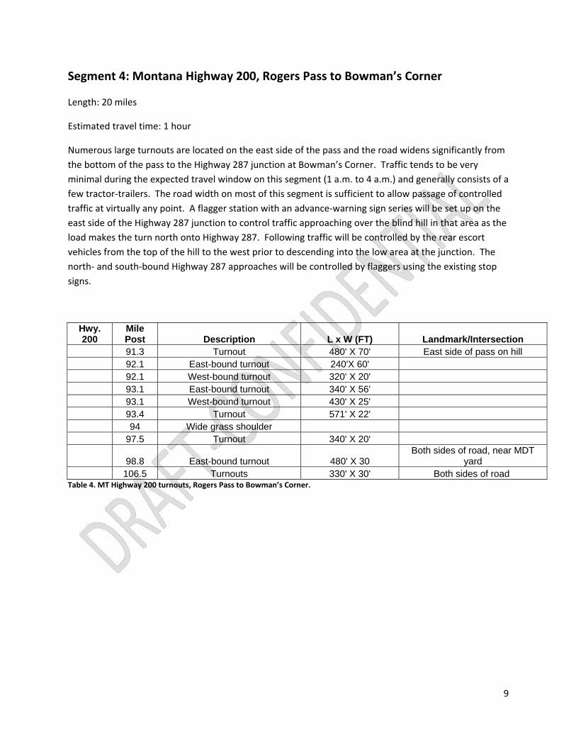
Segment 4: Montana Highway 200, Rogers Pass to Bowman’s Corner
Length: 20 miles
Estimated travel time: 1 hour
Numerous large turnouts are located on the east side of the pass and the road widens significantly from
the bottom of the pass to the Highway 287 junction at Bowman’s Corner. Traffic tends to be very
minimal during the expected travel window on this segment (1 a.m. to 4 a.m.) and generally consists of a
few tractor‐trailers. The road width on most of this segment is sufficient to allow passage of controlled
traffic at virtually any point. A flagger station with an advance‐warning sign series will be set up on the
east side of the Highway 287 junction to control traffic approaching over the blind hill in that area as the
load makes the turn north onto Highway 287. Following traffic will be controlled by the rear escort
vehicles from the top of the hill to the west prior to descending into the low area at the junction. The
north‐ and south‐bound Highway 287 approaches will be controlled by flaggers using the existing stop
signs.
Hwy. 200
Mile Post Description L x W (FT) Landmark/Intersection
91.3 Turnout 480' X 70' East side of pass on hill 92.1 East-bound turnout 240'X 60' 92.1 West-bound turnout 320' X 20' 93.1 East-bound turnout 340' X 56' 93.1 West-bound turnout 430' X 25' 93.4 Turnout 571' X 22' 94 Wide grass shoulder 97.5 Turnout 340' X 20'
98.8 East-bound turnout 480' X 30 Both sides of road, near MDT
yard 106.5 Turnouts 330' X 30' Both sides of road
Table 4. MT Highway 200 turnouts, Rogers Pass to Bowman’s Corner.

10
Segment 5: U.S. Highway 287, Bowman’s Corner to Augusta
Length: 20 miles
Estimated travel time: Less than 1 hour
As indicated by the MDT traffic control data, few vehicles travel this segment during proposed travel
hours. Poteet Construction has moved several loads along this route and has rarely encountered more
than one or two passenger vehicles on this segment during proposed travel hours. Tractor‐trailers have
not been encountered at all. Numerous small turnouts and approaches are located throughout this
segment, providing ample opportunity to move oncoming passenger cars off the road and allowing the
load to pass. Following traffic, if encountered, will likely be required to follow the load until reaching
Augusta. However, the load should be able to travel this segment quickly and delays to the following
traffic will be minimal. PCI personnel have yet to encounter any following traffic on this segment during
proposed travel hours.
NOTE: Travel through the town of Augusta requires special consideration and is detailed in Section 4
of this document.
Special Traffic Control Considerations, Bowman’s Corner to Augusta
As the load approaches the Highway 287 junction from the west, one flagger will be dispatched to the
town of Augusta to convey information regarding road conditions and possible impediments to travel to
the road manager (via radio and cell‐phone). Turnouts large enough to move the load off the road do
not currently exist on this segment, necessitating an “all‐clear” confirmation before the load continues
travel to Augusta. Under no circumstances will the load continue travel past Bowman’s Corner prior to
receiving the all‐clear message. Southbound commercial traffic that cannot be moved past the load on
this segment will be given the option of “right‐of‐way” or to remain in Augusta while the load traverses
this segment. The flagger will remain at the Augusta town border during this segment of travel to
communicate information to the pilot vehicles about traffic travelling south and to advise motorists of
the operation.
NOTE: Due to the limited width of this segment and the lack of large turnouts or intersections, any
impediment to load movement will require rapid implementation of an emergency plan to minimize
delays to the travelling public. In the event a catastrophic breakdown occurs on this segment and the
load cannot be moved immediately, the flagger stationed in Augusta may be instructed to inform
southbound motorists of the situation and provide information regarding an alternate route to Highway
200. Another flagger will be stationed at the Highway 200 junction with similar instructions. (Please see
the “Emergency Response Plan” section of this document for more details.)

11
Segment 6: U.S. Highway 287, Augusta to Choteau
Length: 24 miles
Estimated travel time: Less than 1 hour
Traffic remains light on this segment and reliably consists of passenger vehicles. Numerous small
turnouts and several intersections and wide areas will provide opportunities to move traffic around
from the rear of the load. A few larger turnouts exist, providing emergency stopover parking for the
load. Depending on load length, these turnouts may not be large enough for loads to move completely
off the road and may require a one‐lane, two‐way flagging operation for the duration of an extended
emergency stop‐over (please see the “Emergency Response Plan” section of this document for details of
this operation).
NOTE: Travel through the town of Choteau requires special consideration and is detailed in Section 4
of this document.
US Hwy. 287 Mile Post Description L x W (FT) Landmark/Intersection
40.5 Turnout, opposite side 166' X 28' 41.9 Turnout 150' X 30'
45 Wide intersection, traffic
clearing, emergency parking Fairfield Junction 57.5 Turnout 120' X 40' Egg Mt Historic Point
Table 5. U.S. Highway 287 turnouts, Augusta to Choteau.

12
Segment 7: U.S. Highway 89, Choteau to Montana Highway 44 Junction
Length: 43 miles
Estimated travel time: 1.5 – 2 hours
With a few exceptions (mostly just south and north of the town of Dupuyer where the road widens
appreciably), this segment of the route remains relatively narrow with plenty of turnouts for traffic‐
clearing opportunities. Between Bynum and Dupuyer, the road is narrow and winds somewhat sharply
through hilly terrain. This section has required slower travel and maneuvering for some longer loads.
Few traffic‐clearing opportunities exist in this section, requiring extra consideration for oncoming traffic.
Flaggers will be stationed far ahead of the load to relay information about oncoming traffic prior to the
load entering these areas. If there is any doubt that oncoming traffic will not be able to be safely
conducted past the load at any point along this route or adherence to the 10‐minute Rule cannot be
assured, the load will halt at a traffic clearing area prior to this section and the oncoming traffic will be
given right‐of‐way. However, traffic has been nearly non‐existent on this segment during proposed
travel hours. The towns of Bynum and Dupuyer have wide shoulders allowing for clearing of traffic in
either direction and numerous turnouts provide emergency parking.
As with the Highway 200/287 junction, a flagger will be posted north of the Hwy 44 junction to control
southbound traffic as the load makes the east‐bound turn onto MT Highway 44. A flagger and pilot car
will be dispatched to the town of Valier to relay information about traffic and road conditions prior to
the load arriving at the junction.
U.S. Hwy.
89 Mile Post Description L x W (FT) Landmark/Intersection
42 Off street parking area 190' X 50' Stage Stop Inn 43.3 Turnout 240' X 25' 45 Turnout 130' X 20' 46.5 Turnout, opposite side 182' X 20'
55 Turnout 170'X 70' Town of Bynum, private
property 62.5 Turnout 100 'X 25' Jct 219 & 89 70.5 Wide road to Dupuyer 75.4 Wide road, shoulders, in town 800' X 25' Town of Dupuyer 76 Rest area, no overhead obstruction 300' X 40' Rest area, just north of Dupuyer
Table 6.U.S. Highway 89 turnouts, Choteau to MT Highway 44 Junction.

13
Segment 8: Montana Highway 44 to Valier
Length: 14 miles
Estimated travel time: 20 ‐25 minutes
MT Highway 44 from the U.S. Highway 89 junction to the town of Valier is relatively straight and wide
with plenty of opportunities to clear traffic in either direction at any point. A flagger and pilot car will be
stationed on the west end of Valier to advise the load supervisor and pilot cars of any traffic travelling
west on Highway 44 before the load begins travel east from the Highway 89 junction. Traffic is very light
during proposed travel hours and has been virtually non‐existent after 2 a.m. In case of emergency, the
load may be safely parked either at the Highway 89 junction or at a turnout near mile post 4.
NOTE: Travel through the town of Valier requires special consideration and will be detailed in Section
4 of this document.
MT Hwy.
44 Mile Post Description L x W (FT) Landmark/Intersection
0 Turnout 200' X 10' Junction 89 & 44 4.2 Turnout 280' X 20'
Table 7. MT Highway 44 turnouts, U.S. Highway 89 junction to Valier.

14
Segment 9: Montana Secondary 358, Valier to the U.S. Highway 2 Junction (Cut
Bank)
Length: 28 miles
Estimated travel time: 45 minutes ‐ 1 hour
This segment has been almost entirely clear of traffic during proposed travel hours. The road is easily
negotiated by high and wide loads and several opportunities exist to clear traffic in either direction.
Flaggers and pilot cars will be spaced well ahead of the load prior to departing Valier to convey traffic
and road condition information to the load manager. As with previous junctions, a flagger will be placed
on the west side of the Hwy 2 junction to control traffic headed east as the load makes the right‐hand
turn east onto Hwy 2.
NOTE: Travel through the town of Cut Bank requires special consideration and will be detailed in
Section 4 of this document.
Sec. 358
Mile Post Description L x W (FT) Landmark/Intersection
0.1 Turnout Large, irregular North end of Valier
3 Large gravel intersection 400' X 16' Double approach intersection
17.7 Turnout, opposite side 138' X 55' Glacier County Line Table 8. Secondary 358 turnouts, Valier to U.S. Highway 2 junction.
Segment 10: Secondary 213, Cut Bank to Secondary 214 Junction
Length: 7 miles
Estimated travel time: 20 minutes
Once past the more populated areas of Cut Bank, the load should travel quickly. Traffic in either
direction has rarely been encountered during proposed travel times and is easily managed by traffic
control personnel with very little delay.

15
Segment 11: Secondary 214, from Junction with Secondary 213 to Port of
Sweetgrass
Length: 41 miles
Travel time: 1.5 – 2 hours
This segment begins as a paved, two‐lane rural road with turnouts for traffic clearing and emergency
parking located at mile posts 2 and 6. The road surface narrows and deteriorates considerably
beginning approximately 13 miles from the Highway 213 junction. The rough, narrow conditions persist
for about 5 miles before giving way to a wide engineered gravel road approximately 18 miles north of
the Highway 213 junction. Advance traffic control personnel will be stationed far enough ahead of the
rough, narrow section to inform the load manager of any oncoming traffic since almost no opportunity
to clear traffic from either direction is to be found. As with other narrow sections of road with few
traffic‐clearing opportunities, traffic will either be held while the load completes this section or the load
will pause at a traffic‐clearing area until the oncoming traffic has passed to ensure adherence to the 10‐
minute Rule. The gravel portion of this segment is wide enough to easily clear escorted traffic in either
direction at any point. Most traffic associated with the Port of Sweetgrass is via Interstate 15. As
indicated by the Montana Department of Transportation traffic count data, traffic on this segment
during proposed travel hours has been virtually non‐existent during past load moves.
NOTE: Travel through the town of Sweetgrass requires special consideration and will be detailed in
Section 4 of this document.
Hwy. 214
Mile Post Description L x W (FT) Landmark/Intersection
2 Turnout N/A 5.9 Turnout N/A Farm access approach 13.5 Road narrows
Table 9. Secondary 214 turnouts, Secondary 213 junction to Port of Sweetgrass.
16
SECTION 3: TRAFFIC CONTROL OVERVIEW
The dimensions of the proposed loads will prevent traffic from travelling past a moving load without
assistance from traffic control personnel on most of the proposed route. The state of Montana requires
that the travelling public shall not be stopped for more than 10 minutes (Ten‐minute Rule). This rule will
apply mainly to traffic approaching the load in the opposite lane of travel (on‐coming traffic). MDT
stipulates that traffic approaching from the rear of the operation, if not stopped, may not be delayed for
more than 20 minutes. This rule necessitates a clearly defined and coordinated traffic control plan using
a combination of advance warning signs and devices, flaggers, pilot vehicles and load escort vehicles
(Figure 1). Each of these four components will be detailed separately in this section.
This proposal utilizes traffic volume data gathered by the Montana Department of Transportation (MDT)
in order to determine the hours of permitted travel that are least likely to cause excessive delays and
inconvenience to the travelling public. Based on this traffic volume data, load movement will be
restricted to the hours between 10 p.m. and 6 a.m., from Sunday night through Friday morning, in order
take advantage of low traffic volumes and to avoid conflicts with commuters and school bus traffic.
Every effort will be made to ensure adherence to the MDT rules concerning delays to the travelling
public.
NOTE: The following traffic management plan has been developed by PCI while escorting loads over
the proposed route since 2011. It has been refined so that delays to traffic are typically well under 10
minutes for oncoming traffic and 20 minutes for following traffic. PCI has developed this system in
response to the challenges of adhering to MDT mandated traffic delay limits while escorting loads
over the proposed route. Spacing flaggers far ahead of the load minimizes the number of personnel
and devices needed to safely contend with oncoming traffic. Pilot cars are able to escort oncoming
traffic towards the load to a safe clearing location. This allows the load to remain moving and reduces
the time needed to complete the route. Oncoming traffic is typically held for no more than 2 to 3
minutes at the flagger station and are escorted as close to the load as possible, reducing waiting time
at the clearing location to 2‐3 minutes or less. In many instances, total delays to oncoming traffic are
less than 5 minutes and rarely approach 10 minutes. Moving traffic from the road and allowing the
load to pass provides many more opportunities for traffic clearing than having the load move from the
road at an appropriate turnout. An added bonus is that the building of new turnouts has not been
necessary. Holding traffic at flagger stations had proven to be very ineffective and resulted in
unpredictable delay times and slowed load travel considerably. On at least two occasions, MDT
personnel monitored the operation and conveyed their approval of the overall traffic management
plan to PCI personnel. It is worth noting that other traffic control and escort companies have since
adopted this method and it is now the “standard” means of traffic management for oversized load
moves.

17
Advance Warning Devices
All flagger stations will be preceded by an appropriate advance warning sign series (refer to Figure1).
These are a five‐sign series designed to safely reduce traffic speed and to warn oncoming traffic of the
flagger’s presence. All devices and spacing will be in compliance with MUTCD standards for stopping
traffic on two‐lane highways. In some circumstances, a Variable Message Board (VMB) may be used on
busy highways to alert traffic to the operation well in advance of the flagger stations. The VMB is a high‐
visibility electronic sign that can display up to three pages of programmable text and can be very
effective at communicating information to traffic.
Flaggers
Flagger stations will be employed in advance of the load to warn oncoming traffic of the approaching
load and to convey information about traffic and road conditions to the pilot cars and load manager
(Figure 1). Flagger stations will be located in areas with long‐distance visibility to oncoming traffic,
avoiding blind curves and hills. When determining flagger station locations, consideration is also given
to providing ample space along the shoulder or turnout to move traffic off the road to allow passage of
the load. Depending on the speed of the load, flagger stations will be located from 5 to 10 miles or
more in advance of the load. A minimum of two flagger stations will be employed at all times in order to
maintain a safe buffer in front of the load and to provide sufficient time for pilot cars to move traffic up
to a safe clearing area before reaching the load.
The flagger at each station is responsible for stopping all oncoming traffic and speaking to each driver.
Drivers are informed of the operation and asked if they are experiencing an emergency that would
necessitate immediate passage around the load (protocol for dealing with such emergencies will be
detailed in the “Emergency Response” section of this document). The flagger, at the instruction of the
lead pilot car, will then either send the traffic up to the next flagger station or pilot car, or will direct the
vehicles to the side of the road (or turnout) to allow for passage of the load. The flaggers will “leap‐
frog” each other as the operation progresses to maintain proper spacing in advance of the load. All
flagger vehicles are equipped with overhead flashing lights and spot lights to illuminate the flagger. All
flaggers will be equipped with the necessary and required reflective attire and equipment for nighttime
flagging.
Note: Flaggers will not be permitted to stop oncoming traffic unless and until a proper advance
warning sign series is in place.
Pilot Vehicles
In order to maintain adherence to the 10‐minute rule, a minimum of three pilot vehicles will be
employed to escort oncoming traffic between the flagger stations and the load. The pilot vehicles will
circulate continuously between the lead escort vehicle and the nearest flagger station to minimize
delays and to ensure that no traffic is allowed to approach the load without an escort. Pilot vehicles are

18
responsible for instructing the flaggers to either hold traffic at their location (if the load is approaching
the station), or to instruct the oncoming vehicles to continue towards the load (depending on the
average speed of the load and its distance to the flagger station). As mentioned in the previous section,
the flaggers will be stationed from 5 to 10 miles or more in advance of the load. This distance requires
that the pilot vehicles maintain relatively even spacing between the flagger station and the lead escort
vehicle in order to maintain radio communication. One pilot vehicle is pre‐determined to be the “lead”.
The driver of the lead pilot vehicle will be an ATTSA certified Traffic Safety Supervisor (TSS). The lead
pilot vehicle will remain in radio contact with the lead escort vehicle and is ultimately responsible for
managing the pilot vehicles and the flaggers. One of the pilot vehicles is typically stationed closer to the
near flagger station in order to relieve the flagger and to pick up advance warning signs as the operation
progresses. This leaves one pilot vehicle to travel as needed to escort oncoming traffic and to relay
information between the advance traffic control personnel and the load manager. (All three pilot
vehicles will be involved in escorting vehicles to a safe passing area as traffic volume dictates.)
In the event that there is sufficient time to bring vehicles towards the load, the pilot vehicle will use the
information from the flagger about the oncoming traffic (number and type of vehicles) and will position
the pilot vehicle facing towards the load. As the oncoming traffic approaches, the pilot vehicle will begin
moving towards the load to a pre‐determined location deemed wide enough to allow the oncoming
traffic to pull to the side of the road and allow the load to pass. These locations may be identified by the
pilot vehicle or by the lead escort vehicle. When the stopping location is reached, the pilot vehicle
operator will stop in the road, exit the vehicle and instruct the motorist(s) to move to the shoulder or
turnout. The operator then will speak to the motorist(s) again, informing them of the operation and
that they are free to continue travel only after the load has passed. The lead escort vehicle will relieve
the pilot vehicle and hold traffic until being relieved in turn by the load manager escort vehicle. At no
time will un‐escorted traffic be permitted to approach the load. The number of advance personnel and
vehicles (two flaggers, three pilot vehicles and two lead escort vehicles) ensures multiple safeguards
against unescorted vehicles approaching the load from the front.
Escort Vehicles
Depending on the dimensions and configuration of the loads, three to four escort vehicles will
accompany each individual load on the entire route from Bonner to Sweetgrass. These will include at
least one following vehicle and two lead vehicles. The following escort vehicle(s) will follow the load at a
distance of approximately 100 yards. The rear‐most escort vehicle will be responsible for alerting the
load manager of following traffic and will also be responsible for waving following traffic around the
load at the instruction of the load manager when the load and all oncoming traffic has been halted.
Clearing of following traffic will be directed by the load manager and can be accomplished at any wide
area or turnout on the route. Following traffic is most prevalent on Highway 200 can be cleared at many
locations. MDT rules require that following traffic, if not stopped, may not be slowed for more than 20
minutes. However, the load manager will make every effort to clear following traffic at every
convenient location and following traffic has reliably been cleared in well under 20 minutes.

19
The lead escort vehicle will travel at a variable distance from the load (0.5 ‐ 2 miles depending on the
speed of the load) and will be primarily responsible for helping to find adequate turnouts for oncoming
traffic and to alert the load manager of road conditions and obstacles in the road. The load manager will
be in the escort vehicle in close proximity to the load or lead support vehicle. This escort vehicle will
also be equipped with a height pole to measure heights of overhead obstructions (i.e., low tree
branches, existing utility lines).
Figure 1. Typical traffic‐clearing procedure for moving load on two‐lane rural roadway.
Controlling Traffic at Approaches
Numerous side roads enter the proposed route. Whenever possible, a flagger station will be located
such that the flagger will be able to stop traffic on the main route while also utilizing an existing stop
sign to control traffic approaching from the side road. When this situation is not feasible, a pilot vehicle
will control approaching traffic from the side road. The pilot car will remain at the intersection until
relieved by the lead escort vehicle, which will hold the position until relieved by the load manager. At
no time will intersecting roadways be left unattended between the closest flagger station and the load.
Private driveway approaches cannot all be controlled in this manner as they are far too numerous. The
proposed number of escort and pilot vehicles in advance of the load has proven to be sufficient to
observe and provide warning of vehicles entering the route from private drives. Traffic entering from

20
private drives and side roads will be managed in the same fashion as oncoming traffic on the main route
and will not be delayed more than 10 minutes.
Communication
Communication between load operation personnel and traffic control personnel will be primarily
achieved through the use of two‐way radios. All personnel tasked with traffic safety will carry two‐way
radios with at least two dedicated proprietary channels in case of outside interference. The distance
over which the operation may be spread, with flagger stations being several miles ahead of the load,
necessitates efficient relaying of information through the circulating pilot cars to the load manager and
lead pilot car.
Cell phones may also be used to convey information, especially via text messaging. Text messages can
be received even in areas with a minimum of cell phone coverage. This has proven to be especially
useful in conveying information to the load manager about road conditions from personnel far in
advance of the operation. With changing road conditions in the winter and few options for stop‐over
parking, this information can be invaluable in determining when and where the load move should be
suspended due to inclement weather or other emergency scenarios. All personnel sending and
receiving text messages will do so from stopped vehicles in a safe location off of the lanes of travel.
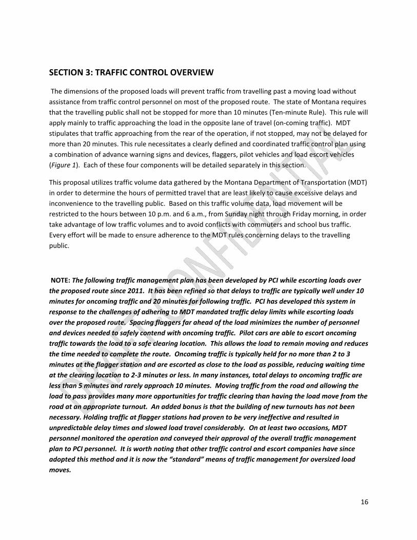
Emergency Breakdown Response Plan
In the event that the load experiences a breakdown in an area where removal from the roadway is not
immediately feasible, an emergency traffic control plan will be implemented. In addition to the advance
warning sign series used for flagging stations, an advanced warning sign series will be carried by one
lead and one follow escort vehicle. These signs can be set up quickly in the event of an emergency to
facilitate a standard two‐way, one‐lane flagging operation around a disabled load (Figure 2). All escort
and pilot vehicles will be operated by flaggers trained and certified by ATSSA. All traffic control and
escort vehicles will be equipped with hand‐held, two‐way radios for communication outside of the
vehicle, as well as a stop/slow paddle and safety‐cone flashlight for traffic control. An emergency
flagging operation can be maintained day or night for an indefinite period. All non‐essential vehicles and
personnel will be moved off the road in order to keep the flagging operation as short as possible and
minimize delays to the travelling public.
21
Figure 2. Typical procedure for clearing traffic on two‐lane rural road with lane obstruction.
Civilian Vehicle with Medical or Other Emergency
As mentioned in the Flagger section previously, the flagger is responsible for speaking directly with each
driver stopped at his or her location. Each driver will be specifically asked if he or she is experiencing an
emergency necessitating quick passage past the operation. In the event that an emergency is reported,
the driver will be instructed to continue past the flagger towards the load. The flagger will provide a
description of the vehicle to the nearest pilot vehicle operator who will then pick up and escort the
vehicle to the load as quickly as is deemed safe. Information about the vehicle and situation will be
relayed to the load manager, who will halt the load at the appropriate time and location in order to
ensure safe and quick passage of the vehicle around the load. All efforts will be made to minimize delay
to a motorist reporting an emergency.

22
Emergency Vehicle Passage
Similar to the above scenario, any official emergency response vehicle will be given priority passage past
the operation. The emergency vehicle will be given more leeway to travel unescorted if necessary,
provided it is equipped with proper emergency lights and sirens. The load manager will be apprised of
the situation as soon as possible and will halt the load and all following traffic to allow safe passage of
the emergency responder. An emergency channel scanner will be carried by a designated escort vehicle
at all times in order to convey emergency information to the load manager and traffic control personnel.
23
SECTION 4: TRAFFIC CONTROL DETAIL, RURAL COMMUNITIES
The proposed route travels through the towns of Lincoln, Augusta, Choteau, Valier, Cut Bank and
Sweetgrass. While none of these towns present any real impediments to travel, special consideration is
afforded them in this document due to higher population densities and maneuvering requirements.
As indicated by the MDT traffic count data, traffic volume in these towns is negligible during proposed
travel hours.
The route through each town will be described separately in this section, with a map showing the
specific route through each for reference purposes. Figures 3 and 4 are standard drawings for
controlling traffic at intersections and turns.

24
Figure 3. Typical procedure for traffic control in rural community, no turns required.
Figure 4. Typical procedure for traffic control in rural community , with turn.

25
Lincoln, Montana
The town of Lincoln requires no turns on the part of the load. Traffic volumes are low during proposed
travel times and traffic is easily controlled by flaggers, pilot cars and escort vehicles. The road through
town is sufficiently wide with shoulders and parking areas providing sufficient room to hold traffic as the
load passes.
One flagger will be stationed at the east end of town to control traffic approaching town from the east.
The remaining pilot and escort vehicles will be stationed at each intersection as the load approaches to
briefly block traffic approaching from side streets. Travel through the town of Lincoln should be
completed in approximately 10 minutes.
Detail of proposed route, Lincoln, Montana.

26
Augusta, Montana
Loads entering the town of Augusta will be required to negotiate a 90 degree turn from Highway 287
northeast onto Main Street. PCI has escorted several loads through Augusta and all have been able to
negotiate the turn onto Main Street with little difficulty. Traffic will be held on Main Street to the east
of the intersection as well as on all approaches coming into the intersection. After the load has made
the turn, travel through town will take approximately 20 minutes to complete. One flagger will be
stationed at the Warden Road intersection northeast of town to control traffic traveling into town on
Highway 287. The remaining pilot and escort vehicles will be stationed at intersections to briefly hold
traffic as the load approaches.
Detail of proposed route, Augusta, Montana.

27
Choteau, Montana
Loads will enter Choteau on Highway 287 north. A round‐about at the junction with Highway 89 cannot
be negotiated in the normal fashion with loads of the proposed dimensions. Instead, the load will travel
against the normal traffic flow for the short segment of the northwest corner of the round‐about.
Traffic control vehicles and personnel will be stationed at intersections as the load proceeds through
town and will block traffic at the round‐about as the load makes the turn onto Highway 89 north. As the
load negotiates the round‐about, one flagger will be sent ahead to the Airport Road intersection to hold
traffic entering town from the north on Highway 89.
As the MDT traffic count data indicates, traffic in Choteau during proposed travel hours is minimal.
Travel through Choteau should be completed in approximately 20 minutes.
Detail of proposed route, Choteau, Montana.
28
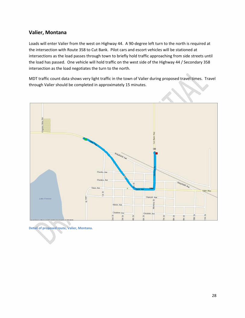
Valier, Montana
Loads will enter Valier from the west on Highway 44. A 90‐degree left turn to the north is required at
the intersection with Route 358 to Cut Bank. Pilot cars and escort vehicles will be stationed at
intersections as the load passes through town to briefly hold traffic approaching from side streets until
the load has passed. One vehicle will hold traffic on the west side of the Highway 44 / Secondary 358
intersection as the load negotiates the turn to the north.
MDT traffic count data shows very light traffic in the town of Valier during proposed travel times. Travel
through Valier should be completed in approximately 15 minutes.
Detail of proposed route, Valier, Montana.

29
Cut Bank, Montana
Loads will approach Cut Bank from the intersection of Secondary 358 and U.S. Highway 2. Flaggers will
be stationed at the intersection to control traffic on Highway 2 as the load negotiates the 90‐degree turn
onto Highway 2 east (see figure 5 below). After the load convoy has completed the right‐hand turn onto
Highway 2, the procession will stop briefly at the junction to allow traffic control personnel to stage at
intersections in town. The load will make a left‐hand turn at the newly constructed railroad overpass to
access north‐bound Secondary 213. Flaggers and pilot cars will hold traffic on Main Street (Highway 2)
southeast of the intersection with the overpass and ahead of the load on the northwest side of the
overpass (see figure 6 below).
MDT traffic count data shows that vehicle counts in and around the town of Cut Bank are minimal
during proposed travel hours. Travel through the town of Cut Bank will take approximately 30 minutes.
Detail of proposed route, Cut Bank, Montana. NOTE: Map detail approximates the location of the newly constructed railroad overpass that will be used by loads traveling through Cut Bank.

30
Figure 5. Traffic control plan detail, Route 358 – U.S. Highway 2 junction, Cut Bank.
Figure 6. Traffic control plan detail, U.S. Highway 2 – Route 213 junction, Cut Bank.

31
Sweetgrass, Montana
The Port of Entry‐Sweetgrass is the terminus of the route through the state of Montana. The load will
approach the town of Sweetgrass on Secondary 214 from the west. Traffic control personnel will stage
at the Interstate15 interchange (the load travels over I‐15) and other intersections along the route
through town to briefly hold traffic as the load negotiates the winding route to the parking area near
Central Avenue and Border Road.
MDT traffic count data indicates low traffic volumes in the town of Sweetgrass during proposed travel
hours. Most traffic in and out of the Port is via I‐15. Any traffic encountered in town will be easily
controlled by traffic control personnel. Travel through the town of Sweetgrass will take approximately
15 minutes.
Detail of proposed route, Sweetgrass, Montana.

32
SECTION 5: OVERNIGHT AND EMERGENCY PARKING AREAS
The dimensions of the loads assumed in this document will require special consideration for planned
and emergency stop‐over parking along the proposed route. Many turnouts and parking areas along the
route are large enough to accommodate the load and associated support vehicles. These areas are
listed in the table below. Photos of the most likely planned overnight parking areas are included for
reference. The load manager will carry a list of these locations at all times in the event that hazardous
road conditions or other impediments to travel necessitate unscheduled stops.
Loads of the proposed dimensions and configurations should be able to complete the route in two
nights, especially if all overhead utility lines have been mitigated prior to this plan being implemented.
This schedule would require only one designated overnight parking area to be used by each load. The
most likely candidates would be the turnouts on Highway 200 at mile post 106.5. These are two very
large turnouts located just west of Bowman’s Corner. Alternatively, the turnouts at mile post 98.8 are
also large enough to accommodate any load that is likely to travel this route. The size and number of
these turnouts should be sufficient to allow loads to park during the daytime hours without
inconveniencing the travelling public and would likely require no advance closure. In the event that
loads are able to continue on to Choteau in the allotted time, overnight parking is available at the
parking lot adjacent to the Stage Stop Inn on the north end of Choteau (with permission of concerned
parties) or at the turnout just north of town at mile post 43.3. At such time that this plan is being
considered, concerns of all parties involved will be carefully considered in order to arrive at a workable
solution to the challenges that may arise from daytime parking.
Table 10 below lists only turnouts and parking areas at least 240 feet in length and within the public
right of way. Other parking areas on private property or within town borders may be considered with
advanced approval by concerned parties but are not considered here.

33
Route Segment Mile Post Description L x W (FT) Landmark / Intersection Daytime /
Emergency
Hwy. 200 32 Turnout w/overhead
line N/A Clearwater scales
Emergency (o.h. line at
~27')
32.4 Turnout 313' X 36' Daytime
35.3 Turnout 340' X 18' Emergency
50.3 Turnout, opposite side 360' X 30' Bob Marshall Interpretive Sign Daytime
65.3 Turnout 400' X 40' On left hand corner Daytime
66.7 Turnout 305' X 70' On left hand corner Daytime
75 Turnout, opposite side 400' X 70' Old MDT yard Daytime
86.8 Double turnout, both
sides of road 450' X 29' Chain-up / removal area Both
89.8 Double turnout, both
sides of road 420' X 25' Top of Rogers Pass
90.7 Turnout 300' X 30' East side of pass Both
91.3 Turnout, east-bound 480' X 70' East side of pass Both
Turnout, west-bound 320' X 20' Both
93.1 Turnout, east-bound 340' X 56' Both
Turnout, west-bound 430' X 25' Both
93.4 Turnout 571' X 22' Both
94 Wide grass shoulder N/A Emergency
97.5 Turnout 340' X 20' Both
98.8 Double turnout, both
sides of road 480' X 30 Both sides of road by MDT yard Both
106.5 Double turnout, both
sides of road 330' X 30' Both
Hwy. 89 76 Turnout (rest area) 300' X 40' Dupuyer rest area Emergency
43.3 Turnout 240’ X 25’
Hwy. 358 3 Turnout (side road) 400' X 16' Pull in, back out on one leg of
double approach. Both
Table 10. Turnouts and parking areas, overnight and/or emergency.

34
SECTION 6: EMERGENCY RESPONSE PLANS
As with any over‐the‐road equipment transportation, the safety of the motoring public as well as that of
the transportation crew is paramount. The contractors and crews identified in this document are,
without exception, well‐established and proven in their respective fields. This section of the proposal
will outline responses to emergency scenarios that may be expected with a project of this magnitude.
The purpose of the Emergency Response Plan (ERP) is to provide guidance to the transport company
should an emergency situation arise during the transport of a module through the State of Montana.
The plan addresses the most likely emergency situations that could occur while a module is in transit.
The transport company will rely on the expertise of the Transport Supervisor and the traffic safety crews
to follow steps to ensure the safety of the transport crew and the traveling public.
A list of high‐capacity crane and/or towing companies is included at the end of this section.
Transport Equipment Breakdown or Failure Response
Even with the safest of operations, breakdowns and equipment failures are a possibility. Loads of the
dimensions proposed in this document require special consideration due to the nature of the proposed
route.
As mentioned in Appendix C, the Kamag K‐25 hydraulic modular trailers employed by Sarens can be
towed to a safe pullout, in either direction, even with moderate equipment failure. However, in the
event that a catastrophic breakdown occurs and the load cannot be safely moved for a period of time,
the following emergency response will be activated as outlined in the “Emergency Breakdown Response
Plan” in Section 3 of this document. If necessary, repair assistance may be provided by the main
transport facility in Edmonton at any hour of the day or night. In the event that the transport
equipment cannot be repaired on‐site, a standard high‐capacity towing vehicle can be on‐site within two
hours at virtually any location along the route to move the transport equipment to a safe location.
Motor Vehicle Collision, Medical Emergency
In the event that a collision or medical emergency occurs during transport, similar steps as above will be
implemented to ensure the safety of the transport crew and the travelling public. The load manager will
be immediately notified and will decide whether to stop in place or proceed to a safe location off the
road if possible. All non‐essential personnel and vehicles will be cleared from the road to reduce the
size and scope of the incident site. Emergency responders will be notified of the location and nature of
the incident and first aid will be administered to any injured parties by trained first aid responders if
possible. Appropriate traffic control measures will be implemented as necessary to ensure the safety of
all involved and to minimize impacts to the travelling public.
Hazardous Material Spill
All transport support vehicles will carry “spill kits” to be implemented in the event of a hazardous
material leak (i.e. hydraulic oil, fuel, anti‐freeze). The module loads will contain no hazardous fluids. In

35
the event that a spill cannot be contained with equipment on hand, appropriate authorities will be
immediately notified. As with any emergency scenario, the incident site will be minimized as much as
possible and appropriate traffic control measures will be implemented immediately.
Hazardous Weather or Road Conditions
Weather and road conditions will be assessed each day prior to beginning travel. The load manager will
be responsible for determining if forecasted weather conditions are sufficiently hazardous to cancel
travel prior to departure. In the event that road and/or weather conditions deteriorate unexpectedly
during travel, traffic control far in advance of the load and will convey information to the load manager
that may necessitate suspending load travel. With loads of the proposed dimensions, it is imperative
that travel be halted in a safe location under any scenario that could result in the load becoming
stranded en‐route. During winter months, a plow/sanding vehicle may be added to the load convoy to
clear the road of ice or snow and to plow an appropriate turn‐out if an unplanned stop‐over is
necessary.
Incident Involving Load Separating from Transport Equipment
As with any load traveling on public roadways, there exists the possibility that the transport equipment
or load may become disabled to the extent that further travel is not possible without assistance from
equipment and personnel not traveling with the convoy. If the load becomes unstable or detached from
the trailer, a high‐capacity crane and crew will be summoned as quickly as possible to stabilize the load
or remove the affected equipment from the roadway. Included at the end of this proposal segment is a
list of high‐capacity crane operator companies that can respond to an emergency situation and an
estimate of travel time to the incident site.
As with any emergency scenario, the safety of the crew and the travelling public will be the primary
concern. Emergency traffic control measures will be implemented immediately while emergency
responders are notified and injured parties tended to. Spill kits will be deployed to contain any
hazardous fluid spill or leak. If possible, traffic will continue to be directed safely past the equipment on
the regular route of travel. However, with loads of this size travelling on sometimes narrow roadways,
road closure may become necessary. In the event that the route becomes impassable to the travelling
public, traffic control personnel will set up a detour around the affected section of road.
Example
A likely segment of the proposed route to require a closure and detour is the segment of Highway 287
between Bowman’s Corner and Augusta. This is a typical two lane road with little shoulder area and
steeply sloping ditches on both sides. Any incident involving suspension of travel on this section of
roadway would result in a road closure. As mentioned in the “Traffic Control Overview” above, before
the load convoy initiates travel on Highway 287, a flagger will be dispatched to Augusta to advise the
road manager of road conditions and oncoming traffic. A second flagger or pilot car will remain at
Bowman’s corner for the duration of the move to Augusta. In the event that a closure becomes
necessary, these two flaggers will advise motorists of the detour and provide printed maps indicating

36
the detour route (see map below). If necessary, additional traffic control devices, signs and personnel
may be dispatched to key turns along the detour route to further assist motorists. Every effort will be
made by the transportation crew and traffic control personnel to minimize delays and inconvenience to
the travelling public and to reopen the road as quickly and as safely as possible.
PROPOSED EMERGENCY DETOUR ROUTE, HIGHWAY 287 TO AUGUSTA

37
Mobile Crane Operators and Capacities for Emergency Response
Mobile/All Terrain
To
Sweet Grass, MT
To
Missoula, MT
Company Truck/ Crane Capacities
LocationsApproximate Distance
Approximate Mob. Time
Approximate Distance
Approximate Mob. Time
Strongs Crane (406) 259‐8833 40 to 250 Ton Billings, MT 340 mi 14 hrs
350 mi 14 hrs
D & G Crane (406) 721‐6389 Up to 110 ton Missoula, MT 250 mi. 9 hrs 0 mi. 2 hrs
Montana Crane (406) 586‐0909 Up to 140 ton Bozeman, MT 300 mi. 11 hrs 200 mi. 9 hrs
H & H Crane (406) 452‐4614 50 to 300 ton Great Falls, MT 118 mi. 3 hrs 165 mi. 5 hrs
Edmonton, AB 380 mi. 15 hrs 560 mi. 21 hrs
Sterling Crane Red Deer, AB 290 mi. 12 hrs 460 mi. 18 hrs
Calgary #(403) 279‐6585 100 to 800 ton Calgary, AB 200 mi. 9 hrs 370 mi. 15 hrs
Grand Junction, CO 920 mi. 33 hrs 810 mi. 29 hrs
Elko, NV 800 mi. 29 hrs 550 mi. 21 hrs
Myshak Crane (403) 346‐4329 100 to 500 ton Edmonton, AB 380 mi. 15 hrs 550 mi. 21 hrs
Northern Crane(780) 823‐2200 45 to 1200 ton Edmonton, AB 380 mi. 15 hrs 550 mi. 21 hrs
Stampede Crane (403) 548‐8117 65 to 300 ton Calgary, AB 200 mi. 9 hrs 370 mi. 15 hrs
Ness Cranes (888) 784‐1054
50 to 550 ton
Tacoma, WA 750 mi. 27 hrs 490 mi. 18 hrs
Campbell Crane (888) 784‐1054 22 to 500 ton Portland, OR 810 mi. 29 hrs 550 mi. 21 hrs
Wagstaff Crane (801) 277‐3820 Up to 550 ton Salt Lake City, UT 690 mi. 25 hrs 530 mi. 20 hrs
Hite Crane (509) 855‐5025 Up to 440 ton Spokane, WA 460 mi. 18 hrs 200 mi. 9 hrs
Mullan Cranes (208) 547‐4775 Up tp 300 ton Soda Springs, ID 580 mi 22 hrs 420 mi 16 hrs
Mobilization times are based upon 40mph speed & approx. 1.5 hr response to departure time.

38
APPENDIX A: Overnight Parking Areas, Typical Photos
Hwy. 200, Mile Post 65, 5 miles west of Lincoln. (400’ X 40’)
Hwy. 200, Mile Post 107, 3 miles west of Hwy 287 junction. (330’ X 30’)

39
Hwy. 89, Mile Post 44, 4 miles north of Choteau. (240’ X 20’)
Hwy. 89, Mile Post 76 rest area, 1 mile north of Dupuyer. (300’ X 40’)

40
Route 358, Mile Post 3, 3 miles north of Valier, one leg of two‐directional intersection. (400’ X 16’ road width)

41
APPENDIX B: MONTANA DEPT OF TRANSPORTATION TRAFFIC DATA
MT Hwy. 200 MDT traffic count data.
MT Hwy. 200 MDT traffic counter locations.
0
50
100
150
200
250
300
350
400
NUMBER
OF VEH
ICLES
TIME OF DAY, 10 PM THRU 9PM
HWY 200 TRAFFIC DATA
HWY 200, MP 5, 6/28/2011
HWY 200, MP 31, 6/28/2011
HWY 200, MP 82, 5/11/2011
HWY 200, MP 109, 5/12/2011

42
U.S. Hwy. 287 MDT traffic count data.
U.S. Hwy. 287 MDT traffic counter locations.
0
20
40
60
80
100
120
140
NUMBER
OF VEH
ICLES
TIME OF DAY, 10 PM THRU 9 PM
HWY 287 TRAFFIC DATA
HWY 287, MP 20, 7/12/2011
HWY 287, MP 39, 5/24/2011
HWY 287, MP 55, 7/12/2011
HWY 287, MP 64, 5/26/2011

43
U.S Hwy. 89 MDT traffic count data.
U.S. Hwy. 89 MDT traffic counter locations.
0
20
40
60
80
100
120
NUMBER
OF VEH
ICLES
TIME OF DAY, 10 PM THRU 9 PM
HWY 89 TRAFFIC DATA
HWY 89, MP 46, 5/17/2011
HWY 89, MP 55, 5/17/2011
HWY 89, MP 62, 5/17/2011
HWY 89, MP 75, 7/22/2011

44
MT Hwy. 44 MDT traffic count data.
MT Hwy. 44 MDT traffic counter locations.
0
20
40
60
80
100
120
140
160
180
200
NUMBER
OF VEH
ICLES
TIME OF DAY, 10 PM THRU 9 PM
HWY 44 TRAFFIC DATA
HWY 44, MP 0, 7/20/2010
HWY 44, MP 8, 6/30/2011
HWY 44, MP 11, 5/13/2010
HWY 44, MP 13, 5/13/2010
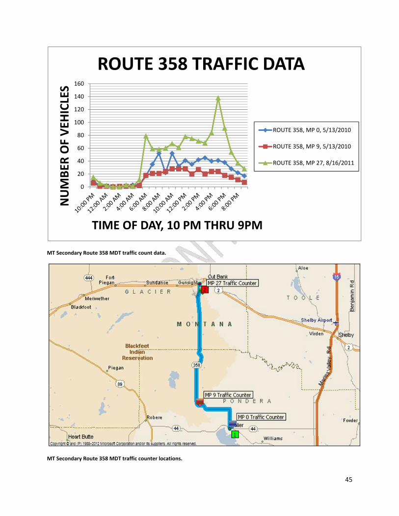
45
MT Secondary Route 358 MDT traffic count data.
MT Secondary Route 358 MDT traffic counter locations.
0
20
40
60
80
100
120
140
160
NUMBER
OF VEH
ICLES
TIME OF DAY, 10 PM THRU 9PM
ROUTE 358 TRAFFIC DATA
ROUTE 358, MP 0, 5/13/2010
ROUTE 358, MP 9, 5/13/2010
ROUTE 358, MP 27, 8/16/2011

46
MT Secondary Route 213 MDT traffic count data.
MT Secondary Route 213 MDT traffic counter locations.
0
50
100
150
200
250
300
350
400
450
NUMBER
OF VEH
ICLES
TIME OF DAY, 10 PM THRU 9PM
ROUTE 213 TRAFFIC DATA
ROUTE 213, MP 0,8/16/2011
ROUTE 213, MP 7,7/19/2011

47
MT Secondary Route 214 MDT traffic count data.
MT Secondary Route 214 MDT traffic counter locations.
0
5
10
15
20
25
30
35
40
45
NUMBER
OF VEH
ICLES
TIME OF DAY, 10 PM THRU 9PM
ROUTE 214 TRAFFIC DATA
RT 214, MP 0, 7/19/2011
RT 214, MP 5, 7/19/2011
RT 214, MP 15, 5/12/2011
RT 214, MP 32, 5/26/2011

48
APPENDIX C: LOAD AND TRANSPORT INFORMATION AND DIAGRAMS
As mentioned in Section 1 above, Sarens Group is the proposed transport contractor for these loads.
Sarens is a world‐wide leader in the lifting and transport of heavy loads and has provided their expertise
in the preparation of this document. Sarens’ Missoula personnel will be involved in the specific
engineering for the load transports, with transport duties to be provided by personnel and equipment
from Sarens’ Edmonton, Alberta, Canada transport facility. Sarens employs rigorous safety training and
certification for their crews as well as a strict and aggressive preventative maintenance schedule for
their equipment. Included in this section are detailed drawings of the load and transport equipment
that can be expected to travel along the proposed route.
Sarens is committed to maintaining a culture of safety during every step of their engineering and
transport duties. To this end, Sarens will be utilizing the latest technology in their transport equipment.
Sarens will employ the Kamag K‐25 SL/3200 hydraulic modular trailer as the platform for transporting
the proposed loads. The Kamag K‐25 trailer is a conventional‐style “pull trailer” with multiple,
redundant components and axels that can be isolated and circumvented in the event of component
failure, allowing for travel to continue uninterrupted to a safe pullout spot for repairs.
The Kamag K‐25 is described as follows:
Highest bending moment on the market By reinforcing the main beam, the permissible bending moment has been increased by 16 %.
Largest oil volume in its class The K25 has an oil tank integrated into the vehicle frame. This oil tank – on the example of a 6‐axle unit – holds a usable oil volume of 220 liters, the largest oil volume in its class. This enables the operation of transport combinations of up to 25 axle lines without an additional tank.
Freely accessible steering rods Unrestricted access to the steering rods ensures easy removal and coupling, without the need for laborious threading of the steering rods. Depending on the configuration, only one end of the steering rod needs to be loosened for re‐linking in a loaded state.
Reinforced lamellar coupling (40 mm) The coupling fins on the K25 have been reinforced to 40 mm. This counters the often rapid wear of the fins, which arises from the steering movements of the vehicle combination in conjunction with a locked coupling cylinder.
Tested attachments and lashings The K25 features attachments and lashings that have been tested and accepted by official agencies. The lashing rings can be used for load securing and also for crane loading of the vehicle. The hole pattern for the cross‐coupling elements is unchanged, which facilitates use of existing equipment.
Steering technology / steering angle The steering hydraulics are secured via a pressure‐relief valve. This prevents damage when steering against resistance, e.g. a curbstone. All the wheel bogies can be aligned in one direction thanks to the
49
new, improved steering geometry. This eliminates the need to turn the rear chassis. The wheel bogies travel universally in the same direction, counteracting the increased wear.
Different designs complete the range The K25 is ‐ depending on requirements ‐ available in diverse versions. KAMAG and SCHEUERLE offer the complete vehicle range for the special requirements of road transport, such as gradients, narrow access or loads with unusually high centers of gravity.
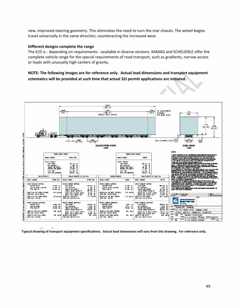
NOTE: The following images are for reference only. Actual load dimensions and transport equipment
schematics will be provided at such time that actual 32J permit applications are initiated.
Typical drawing of transport equipment specifications. Actual load dimensions will vary from this drawing. For reference only.

50
Photo of typical load size and transport equipment.
Front view of typical load size and transport equipment. Conventional trailer width allows for load to overhang edge of road while keeping transport vehicle and trailer on the pavement to facilitate traffic clearing on narrow roads.

51
APPENDIX D: OVERHEAD UTILITY CONFLICTS AND SOLUTIONS
Overhead utility conflicts currently exist at many locations along the proposed route. The cost and
manpower involved in raising or disconnecting these lines for each move are prohibitively high.
Additionally, the safety of the crews working to mitigate utility conflicts during the move is of serious
concern. Utility crews and equipment would be required to stage ahead of the load on sometimes
narrow roads at night with little to no traffic control available.
Alternatively, a permanent mitigation plan is included in this section. The tables below list the parties
responsible for overhead utility conflicts along the proposed routes, utility locations, and the cost of
permanent mitigation of the conflicts. Many of these mitigation plans have been previously submitted
and approved in association with past transport plans, and some conflicts have already been eliminated.
While plan resubmission will be necessary, the process should be somewhat streamlined.

52
Missoula Electric Cooperative Utility Locations and Mitigation Costs
Mark C. Haden, General Manager
406‐541‐6340
Contracted labor and equipment Construction $350,000.00
Contracted labor and equipment Retirement $75,000.00
Materials $110,000.00
Weed control $5,000.00
MEC administrative and misc (10%) $54,000.00
Estimated total project cost $594,000.00
Highway 200
Crossing ID Height Location Crossing ID Height Location
X2 29' 11" MP 1+2287' X45 24' 0" MP 30+1769'
X6 23' 0" MP 4+3621' X49 25' 0" MP 32+3679'
X7 24' 11" MP 5+1052' X50 24' 8" MP 33+367'
X8 25' 8" MP 5+2916' X56 25' 8" MP 40+3966'
X10 21' 2" MP 6+208' X57 23' 7" MP 41 +475
X11 20' 11" MP 6 +3381' X59 23' 10" MP 43+2626'
X12 27' 2" MP 7 +316' X60 30' 0" MP 44+2838'
X13 24' 1" MP 7+1103' X61 19' 4" MP 45+511'
X14 24' 8" MP 7+1919' X62 27' 0" MP 45+3519'
X15 26' 11" MP 7+2690' X63 26' 0" MP 47+5140'
X20 32' 0" MP 9+2627' X65 26' 0" MP 48+2896'
X21 21' 6" MP 9 =3219' X66 18' 9" MP48+4530'
X27 25' 8" MP 12+3058' X71 24" 0" MP 50+3187'
X29 25' 11" MP 13+54' X72.5 30' 0" MP 52+1701'
X31 23' 0" MP 14+3893' X73 23' 11" MP 52+3150'
X32 29' 0" MP 14+4247' X74 29' 6" MP 52+4691'
X33 22' 4" MP 15+1076' X75 29' 6" MP 57+3905'
X35 25' 7" MP 15+4999' X76 21' 8" MP 59+3766'
X36.5 24' 3" MP 20+2079' X77 27' 2" MP 60+00'
X37 26' 3" MP 22+1814' X78 23" 0" MP 61+3741'
X40 26' 8" MP 26+1890' X78.5 30' 0" MP 62+5116'
X44 30' 0" MP 30+870' X79 20' 6" MP 63+1162'

53
Northwestern Energy Utility Locations and Mitigation Costs
Helena Division Crossings, Highway 200, Bonner to Bowman’s Corner
Crossing Location Estimated cost Crossing Location Estimated cost
1 MP 68+0' Combined with 2 32 MP 73+422' $19,518.82
2 MP 68+950' $52,810.59 33 MP 73+1214' $17,340.20
4 MP 68+3696' $28,330.08 34 MP 73+3168' $16,542.75
6 MP 69+264' $6,139.77 35 MP 73+3432' $10,093.50
8 MP 69+1109' $21,866.65 36 MP 73+4910' $10,093.50
9 MP 69+2006' $31,409.66 37 MP 74+1742' $43,912.64
11 MP 70+581' $25,825.16 42 MP 76+2165' $10,809.19
14 MP 71+581' $22,839.34 44 MP 78+264' Combined with 45
21 MP 71+2482' $24,384.03 45 MP 78+1426' $123,852.59
22 MP 71+2587' $9,712.28 47 MP 81+1848' $8,363.49
23 MP 71+2693' $12,472.74 48 MP 82+317' $16,004.80
24 MP 71+3221' $3,323.66 51 MP 92+1901' $25,520.67
27 MP 71+4118' $21,264.73 58 MP 97+3115' $33,671.22
29 MP 72+528' $31,632.61 59 MP 100+106' $14,877.81
Total Estimated Cost $642,612.48
Great Falls Division Crossings, Highway 358
Crossing Location Estimated cost
59 MP 0 + 200' 12,173.00
Total Estimated Cost 12,173.00

54
Sun River Electric Cooperative Utility Locations and Mitigation Costs
Sun River Electric Cooperative
Robert Anderson
Operations Manager 406‐467‐2526
Hwy. Location
89 MP 66.1
89 MP 70.3
44 MP 5.2
358 MP 2.9
358 MP 6.9
358 MP 8.5
358 MP 10.9
Total Estimated Cost $130,000.00

55
Glacier Electric Cooperative Utility Locations and Mitigation Costs
Glacier Electric Cooperative
Doug Ray
406‐450‐2000
Highway Crossing ID./ Pole Number Location
44 36‐26‐R1 MP 1+886'
358 20‐TB11 MP 27+1959'
213 5‐122 MP 1+561'
213 5‐127 MP 1+623'
213 5‐094 MP 2+2112'
213 5‐048 MP 4+2123'
213 5‐027 MP 5+2023'
214 11‐D36‐R1 MP 7+2640'
214 55‐86‐L1 MP 21+2500'
Town of Cut Bank, 2 crossings
1 Alley between 4th and 5th Ave. NW, 1884' west of North Central Ave and MT 213
2 1057’ west of North Central Avenue and MT 213.
Total Estimated Mitigation Cost $120,000.00
56
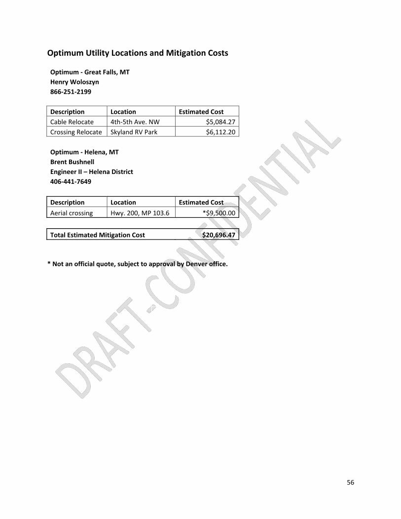
Optimum Utility Locations and Mitigation Costs
Optimum ‐ Great Falls, MT
Henry Woloszyn
866‐251‐2199
Description Location Estimated Cost
Cable Relocate 4th‐5th Ave. NW $5,084.27
Crossing Relocate Skyland RV Park $6,112.20
Optimum ‐ Helena, MT
Brent Bushnell
Engineer II – Helena District
406‐441‐7649
Description Location Estimated Cost
Aerial crossing Hwy. 200, MP 103.6 *$9,500.00
Total Estimated Mitigation Cost $20,696.47
* Not an official quote, subject to approval by Denver office.

57
Overhead Flashing Beacon Locations and Mitigation Costs
Contractor:
Montana Lines, Inc
Great Falls, Montana
James S. Bumgarner, Project Manager/Estimator
406‐727‐1316
A total of 4 overhead flashing beacons are located along the proposed route in the following locations:
The town of Lincoln (Highway 200)
Bowman’s Corner (Highway 200)
The town of Choteau (Highway 89)
The town of Valier (Highways 44 and 358 junction)
Montana Lines, Inc. (MTL) owns the structures and plans required to remove the existing signals and re‐
install them on rotatable, cantilevered poles that can be swung to the side and out of the way of
approaching loads. Plans have previously been submitted to, and approved buy, the Montana
Department of Transportation for the installation of these devices. However, those permits have since
expired and new permits must be issued prior to installation.
Description and Cost of Overhead Signal Mitigation
Item # Location Description Cost
1 Lincoln, Hwy. 200 Flashing beacon rotator installation $70,000.00
2 Bowman's Corner, Hwy. 200 Flashing beacon rotator installation $97,000.00
3 Choteau, Hwy. 89 Flashing beacon rotator installation $152,500.00
4 Valier, MT 44‐MT 358 jct. Flashing beacon rotator installation $158,500.00
Total Mitigation Cost $478,000.00

58
APPENDIX E: Proposal to Provide Environmental Review and Environmental Checklist for Bonner Transportation Plan (BTP) April 29, 2013
Ms. Deb Poteet Poteet Construction Inc. 9435 Summit Driver Missoula, MT 59808
RE: Proposal to Provide Environmental Review and Environmental Checklist for Bonner
Transportation Plan (BTP)
Dear Ms. Poteet,
Tetra Tech appreciates the opportunity to submit this proposal to provide an Environmental Checklist of
assessments of proposed utility crossings and traffic structures which require construction modifications
along the BTP route from Bonner, Montana to the Sweetgrass, Montana Port of Entry on the
U.S./Canada border.
Tetra Tech has developed the following scope of work and cost estimate to provide completion of an
Environmental Checklist as required by MDT for Encroachment/Occupancy (incl. Utility) Permits.
SCOPE OF WORK
Tetra Tech will review the project record and fill out the Environmental Checklist for each site or group of sites, including reviewing maps and publically available data, and conducting field work to verify such things as locations of wetlands and the presence of nearby active eagle nests. Tetra Tech assumes that all location data will be submitted to Tetra Tech at one time so that all of the field verification can be completed in one trip. Tetra Tech also assumes that accurate GPS locations or lat/long information for each location will be provided by Poteet and/or the Client. The estimate cost to complete the checklist assessment is included as Attachment A. Tetra Tech anticipates that it will take approximately 2 to 3 weeks to compile all the information and submit a completed Environmental Checklist. Tetra Tech’s project assumptions for each of the 18 Impact Questions on the Environmental Checklist are included as a narrative to each impact question as well as following the Checklist Conditions and Required Approvals.
Tetra Tech will provide a project manager to oversee the environmental assessment of proposed utility
crossings and traffic structures which require construction as part of permitting the BTP. The project
manager will be responsible for all communications with Poteet Construction and the “Client” as well as
correspondence with MDT Environmental Service Bureau and/or Transportation Planning pertaining to
the Environmental Checklist and its approval. The project manager will be responsible for all
Environmental Checklist submittals, the project budget and timeline, and records retention.

59
ENVIRONMENTAL CHECKLIST
Actions that qualify for Categorical Exclusion under MEPA and/or NEPA (ARM 18.2.261 and 23 CFR
771,117) for Encroachment/Occupancy Permits are defined by answering 18 impact questions:
1. Will the proposed action impact any known historical or archaeological sites? Tetra Tech
assumes that cultural review on a similar transportation haul project (e.g. the Kearl Project) is
sufficient for the Bonner Transportation Plan (BTP) put forth by Poteet Construction and the
“Client”. Tetra Tech will reproduce maps of the transportation route with known historical
sites to provide documentation to this impact question.
2. Will the proposed action impact any publicly owned parkland(s), recreation area(s), wildlife or
waterfowl refuge(s)? Tetra Tech will review the proposed action to assess the potential for
impact on any publicly owned parkland, recreation area, or refuge.
3. Will the proposed action impact prime farmlands? (If yes, attach a completed Farmland
Conversion Impact Rating Ad‐1006.) Tetra Tech will review the proposed action to assess the
potential for impact of prime farmland.
4. A. Will the proposed action have an impact on the human environment that may result from
relocations of persons or businesses, changes in traffic patterns, changes in grade, or other
types of changes? Tetra Tech assumes the BTP will address these issues and that Poteet
Construction and/or the Client will supply the necessary analyses to Tetra Tech in order to
document any such impacts on the human environment (i.e. traffic pattern analysis, etc.)
4. B. Has the proposed action received any preliminary or final approval from the local land use
authority? Tetra Tech assumes that, if approval from a local land use authority is warranted,
Poteet Construction and/or the Client will procure approval and will provide documentation
for the Environmental Checklist.
5. For the proposed action, is there documented controversy on environmental grounds? (For
example, has the applicant received a letter of petition from an environmental organization?).
Tetra Tech is not aware of any documented controversy on environmental grounds at this
time. Any consultation help required mitigating environmental concerns beyond the initial
Environmental Checklist submittal or deal with permitting constraints due to environmental
controversy is outside the scope of this proposal.
6. Will the proposed action require work in, across or adjacent to a listed or proposed Wild or Scenic River? Tech will review the proposed action to assess the potential to impact a listed or proposed Wild or Scenic River.
7. Will the proposed action require work in a Class I Air Shed or nonattainment area? Tech will
review the proposed action to assess the potential to impact a Class I Air Shed.
8. Will the proposed action impact air quality or increase noise, even temporarily? Tech will
review the proposed action to assess the potential to impact air quality or increase ambient
noise.
9. Will the proposed action have potential to affect water quality, wetlands, streams or other
water bodies? If the answer is YES, an environment related permit or authorization may be
required. Tech will review the proposed action to assess the potential to impact a water
quality, wetlands, streams or other water bodies along the proposed transportation route.
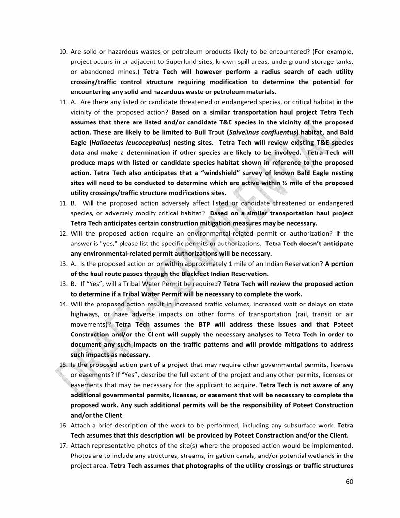
60
10. Are solid or hazardous wastes or petroleum products likely to be encountered? (For example,
project occurs in or adjacent to Superfund sites, known spill areas, underground storage tanks,
or abandoned mines.) Tetra Tech will however perform a radius search of each utility
crossing/traffic control structure requiring modification to determine the potential for
encountering any solid and hazardous waste or petroleum materials.
11. A. Are there any listed or candidate threatened or endangered species, or critical habitat in the
vicinity of the proposed action? Based on a similar transportation haul project Tetra Tech
assumes that there are listed and/or candidate T&E species in the vicinity of the proposed
action. These are likely to be limited to Bull Trout (Salvelinus confluentus) habitat, and Bald
Eagle (Haliaeetus leucocephalus) nesting sites. Tetra Tech will review existing T&E species
data and make a determination if other species are likely to be involved. Tetra Tech will
produce maps with listed or candidate species habitat shown in reference to the proposed
action. Tetra Tech also anticipates that a “windshield” survey of known Bald Eagle nesting
sites will need to be conducted to determine which are active within ½ mile of the proposed
utility crossings/traffic structure modifications sites.
11. B. Will the proposed action adversely affect listed or candidate threatened or endangered
species, or adversely modify critical habitat? Based on a similar transportation haul project
Tetra Tech anticipates certain construction mitigation measures may be necessary.
12. Will the proposed action require an environmental‐related permit or authorization? If the
answer is "yes," please list the specific permits or authorizations. Tetra Tech doesn’t anticipate
any environmental‐related permit authorizations will be necessary.
13. A. Is the proposed action on or within approximately 1 mile of an Indian Reservation? A portion
of the haul route passes through the Blackfeet Indian Reservation.
13. B. If “Yes”, will a Tribal Water Permit be required? Tetra Tech will review the proposed action
to determine if a Tribal Water Permit will be necessary to complete the work.
14. Will the proposed action result in increased traffic volumes, increased wait or delays on state
highways, or have adverse impacts on other forms of transportation (rail, transit or air
movements)? Tetra Tech assumes the BTP will address these issues and that Poteet
Construction and/or the Client will supply the necessary analyses to Tetra Tech in order to
document any such impacts on the traffic patterns and will provide mitigations to address
such impacts as necessary.
15. Is the proposed action part of a project that may require other governmental permits, licenses
or easements? If “Yes”, describe the full extent of the project and any other permits, licenses or
easements that may be necessary for the applicant to acquire. Tetra Tech is not aware of any
additional governmental permits, licenses, or easement that will be necessary to complete the
proposed work. Any such additional permits will be the responsibility of Poteet Construction
and/or the Client.
16. Attach a brief description of the work to be performed, including any subsurface work. Tetra
Tech assumes that this description will be provided by Poteet Construction and/or the Client.
17. Attach representative photos of the site(s) where the proposed action would be implemented.
Photos are to include any structures, streams, irrigation canals, and/or potential wetlands in the
project area. Tetra Tech assumes that photographs of the utility crossings or traffic structures

61
that will be modified will be provided by Poteet Construction and/or the Client. Tetra Tech
will conduct site visits during the windshield survey and photograph each site location.
18. Attach map(s) showing the location(s) of the proposed action(s); Section, Township, Range;
highway or route number and approximate route post(s). Tetra Tech assumes that maps will be
provided by Poteet Construction and/or the Client for each utility crossing or traffic structure
modification in the proposed action.
CHECKLIST CONDITIONS AND REQUIRED APPROVALS
C. If "Yes" is indicated on any of the items, the Applicant must explain the impacts as applicable.
Appropriate mitigation measures that will be taken to avoid, minimize, and/or mitigate adverse
impacts must also be described. Any proposed mitigation measures will become a condition of
approval. Use attachments if necessary. If the Applicant check “no” and the District concludes
there may in fact be potential impacts, the Environmental Checklist must be forwarded to
Environmental Services Bureau for review and approval. Tetra Tech assumes that any
mitigation measures put forth as part of the environmental checklist and permitting phase of
the project will be reviewed and approved by the client before submittal.
D. If “Yes” is indicated in item 11 a. (threatened or endangered species), the Applicant should
provide information naming the particular species and the expected location, distribution and
habitat use in the proposed action area, i.e. within the immediate area of the proposed action;
or, in the general area on occasion (seasonally passes through) but does not nest, den or occupy
the area for more than a few days. This condition is redundant to what is already assumed to
be needed on Question 11. Tetra Tech will map and survey as needed any T&E species habitat
or sensitive habitat.
E. If the applicant checks "Yes" for any item, the approach permit, occupancy agreement or
permit, along with the checklist and supporting information, including the Applicants mitigation
proposal, documentation, evaluation and/or permits must be submitted to MDT Environmental
Services Bureau. Electronic format is preferred. Tetra Tech assumes that the Environmental
Checklist will be submitted with the necessary Occupancy or Encroachment Permits by Poteet
Construction and/or the Client (Tetra Tech will provide the Environmental Checklist to the
permittee). Tetra Tech further assumes that this project will be completed in one
construction phase (i.e. will be permitted through one client) and not completed piece‐meal
where environmental conditions might change between construction phases.
F. When the Applicant check “Yes” to any item, the Applicant cannot be authorized to proceed
with the proposed work until the MDT Environmental Services Bureau and/or Transportation
Planning, as appropriate, reviews the information and signs the checklist. Tetra Tech will not be
responsible for work without authorization to proceed by MDT Environmental Service Bureau
and/or Transportation Planning.

62
G. Applicant must obtain all necessary permits or authorizations from other entities with
jurisdiction prior to beginning the proposed action or activity. The Applicant is solely responsible
for any environmental impacts incurred as a result of the project; obtaining any necessary
environmental permits, notifications, and/or clearances; and ensuring compliance with
environmental laws and regulations. Tetra Tech will not be responsible for any necessary
permit compliance or authorization for the proposed action or activity. This is the Applicant’s
responsibility.
BUDGET
The attached time and materials cost estimate (Attachment A) is based on the scope of work described
above and assumptions presented herein. The cost to provide the Environmental Checklist is estimated
to be $6,410. All fees for this project will be incurred on time and materials basis. Only actual costs
incurred will be invoiced.
If this proposal meets with your approval, please notify Tetra Tech and a Work Order will be developed
for the Scope of Work specified in this proposal to authorize Tetra Tech to proceed. Again, thank you for
the opportunity to submit this proposal. We appreciate our continued relationship with Poteet
Construction and look forward to your reply.
Sincerely,
William Craig
Project Manager/Hydrogeologist
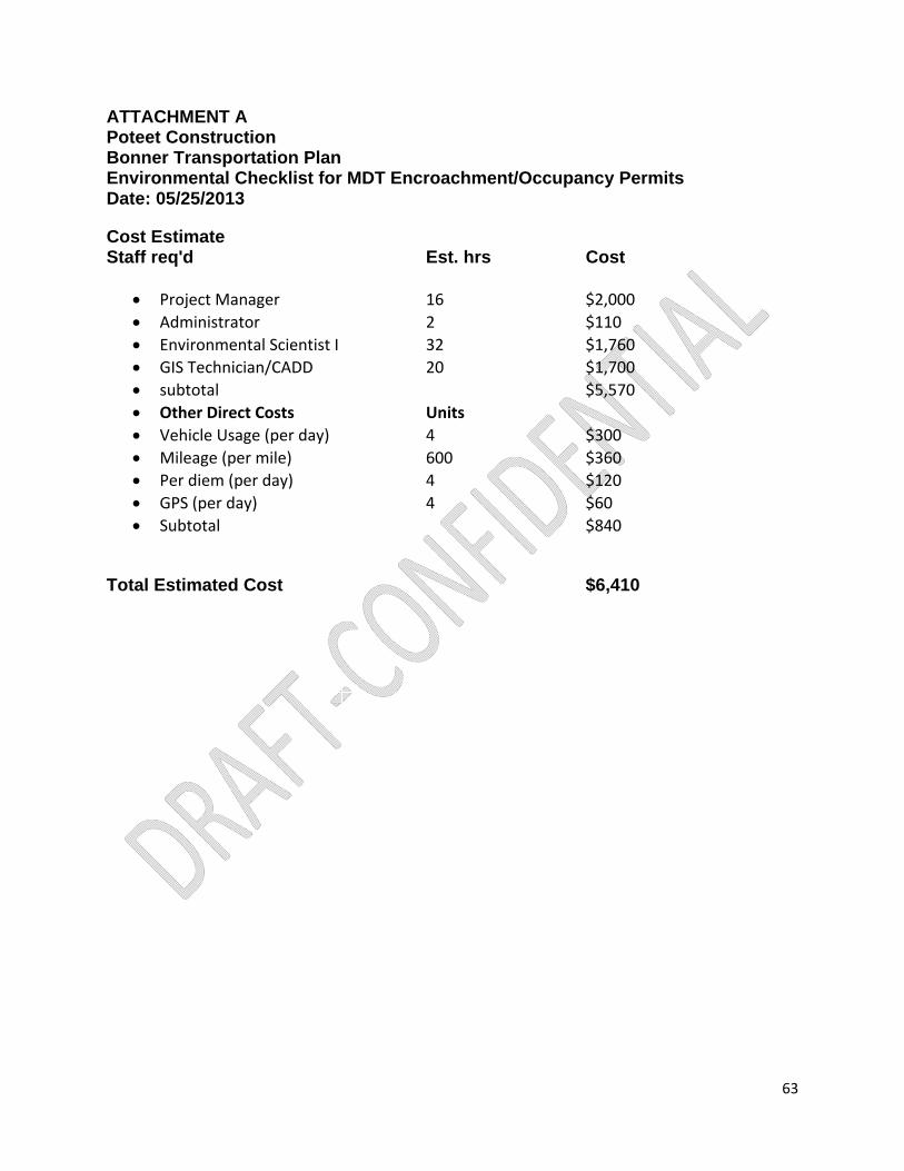
63
ATTACHMENT A Poteet Construction Bonner Transportation Plan Environmental Checklist for MDT Encroachment/Occupancy Permits Date: 05/25/2013
Cost Estimate Staff req'd Est. hrs Cost
Project Manager 16 $2,000
Administrator 2 $110
Environmental Scientist I 32 $1,760
GIS Technician/CADD 20 $1,700
subtotal $5,570
Other Direct Costs Units
Vehicle Usage (per day) 4 $300
Mileage (per mile) 600 $360
Per diem (per day) 4 $120
GPS (per day) 4 $60
Subtotal $840
Total Estimated Cost $6,410