PROJECT MANUAL for the construction of NORFOLK ...ops.noahent.com/BIDDING/17016/NIT Acosta Building...
260
PROJECT MANUAL for the construction of NORFOLK INTERNATIONAL TERMINALS NIT ACOSTA BUILDING RENOVATION— SERVER ROOM VOLUME 1 OF 2 Specifications February 2017 Prepared for: Prepared by:
Transcript of PROJECT MANUAL for the construction of NORFOLK ...ops.noahent.com/BIDDING/17016/NIT Acosta Building...

PROJECT MANUAL for the construction of NORFOLK INTERNATIONAL TERMINALS
NIT ACOSTA BUILDING RENOVATION— SERVER ROOM
VOLUME 1 OF 2 Specifications
February 2017
Prepared for:
Prepared by:


NORFOLK INTERNATIONAL TERMINALS NIT ACOSTA BUILDING RENOVATION – SERVER ROOM
PW\DEN001\000181\684945 TABLE OF CONTENTS FEBRUARY 22, 2017 00 01 10 - i ©COPYRIGHT 2017 CH2M HILL
TABLE OF CONTENTS
VOLUME 1 SPECIFICATIONS
Pages
SPECIFICATIONS
DIVISION 1—GENERAL REQUIREMENTS
01 11 00 Summary of Work .......................................................................... 1- 1 01 26 00 Contract Modification Procedures ................................................. 1- 4 01 29 00 Payment Procedures ....................................................................... 1- 3 01 31 13 Project Coordination ...................................................................... 1- 7 01 31 19 Project Meetings ............................................................................ 1- 3 01 32 00 Construction Progress Documentation .......................................... 1- 7 01 33 00 Submittal Procedures ..................................................................... 1- 8 Supplement: Transmittal of Contractor’s Submittal ...................... 1- 1 01 42 13 Abbreviations and Acronyms ........................................................ 1- 5 01 43 33 Manufacturers Field Services ........................................................ 1- 3 Supplements: Manufacturer’s Certificate of Compliance .................................. 1- 1 Manufacturer’s Certificate of Proper Installation ........................ 1- 1 01 45 16.13 Contractor Quality Control ............................................................ 1- 9 01 50 00 Temporary Facilities and Controls ................................................. 1- 11 01 61 00 Common Product Requirements .................................................... 1- 7 01 77 00 Closeout Procedures....................................................................... 1- 4 01 78 23 Operation and Maintenance Data ................................................... 1- 7 Supplement: Maintenance Summary Form ................................. 1- 2 01 91 14 Equipment Testing and Facility Startup ........................................ 1- 5 Supplements: Unit Process Startup Form ........................................................... 1- 1 Facility Performance Demonstration/Certification Form ............ 1- 1
DIVISION 2—EXISTING CONDITIONS
02 41 00 Demolition ..................................................................................... 1- 6
DIVISIONS 3 THROUGH 25—NOT USED

NORFOLK INTERNATIONAL TERMINALS NIT ACOSTA BUILDING RENOVATION – SERVER ROOM
Pages
TABLE OF CONTENTS PW\DEN001\000181\684945 00 01 10 - ii FEBRUARY 22, 2017 ©COPYRIGHT 2017 CH2M HILL
DIVISION 26—ELECTRICAL
26 05 02 Basic Electrical Requirements ....................................................... 1- 7 26 05 04 Basic Electrical Materials and Methods ........................................ 1- 10 26 05 05 Conductors ..................................................................................... 1- 10 26 05 26 Grounding and Bonding for Electrical Systems ............................ 1- 6 26 05 33 Raceway and Boxes ....................................................................... 1- 27 26 05 70 Electrical Systems Analysis ........................................................... 1- 8 Supplement: Figure 1: Example Arc Flash Labels ...................... 1- 1 26 08 00 Commissioning of Electrical Systems ........................................... 1- 14 26 22 00 Low-Voltage Transformers ............................................................ 1- 3 26 24 16 Panelboards .................................................................................... 1- 7 26 27 26 Wiring Devices .............................................................................. 1- 7 26 36 23 Automatic Transfer Switches ......................................................... 1- 6 26 43 00 Transient Voltage Suppression ...................................................... 1- 5 26 50 00 Lighting .......................................................................................... 1- 11 26 60 00 Horizontal Air Flow Outdoor Resistive Load Bank
(50 to 150 KW) ........................................................................ 1- 8
DIVISIONS 27 THROUGH 49—NOT USED
DRAWINGS (BOUND SEPARATELY)
END OF SECTION

SPECIFICATIONS

NORFOLK INTERNATIONAL TERMINALS NIT ACOSTA BUILDING RENOVATION – SERVER ROOM
PW\DEN001\000181\684945 SUMMARY OF WORK FEBRUARY 14, 2017 01 11 00 - 1 ©COPYRIGHT 2017 CH2M HILL
SECTION 01 11 00 SUMMARY OF WORK
PART 1 GENERAL
1.01 WORK COVERED BY CONTRACT DOCUMENTS
A. The completed Work will provide the Virginia Port Authority with a renovated second floor space, an uninterruptable power supply (UPS) room on the first floor of the existing building, and a renovated server room on the second floor of the Acosta Building. Construction work includes the following items:
1. Connection to new 600A electrical service and duct banks as shown. 2. Renovation of the second floor as shown to include ceiling tile
replacement, carpet replacement, and new wall paint. 3. Beautification of access to the second floor including tile replacement,
handrail improvements, and vinyl coverings on stairs. 4. Creation of a new UPS room on the first floor of the building and
installation of Owner furnished UPSs. 5. Renovation of the server room on the second floor of the building.
Features include: a. Demolition of existing walls and ceiling. b. Window coverings. c. Waterproof membrane between the roof and ceiling of the room. d. New storefront wall. e. Ramp and double door for improved access. f. Raised floor using conductive flooring materials. g. Electrical supply to the server room.
6. Installation of Owner furnished generator and automatic transfer switch (ATS).
PART 2 PRODUCTS (NOT USED)
PART 3 EXECUTION (NOT USED)
END OF SECTION


NORFOLK INTERNATIONAL TERMINALS NIT ACOSTA BUILDING RENOVATION – SERVER ROOM
PW\DEN001\000181\684945 CONTRACT MODIFICATION FEBRUARY 14, 2017 PROCEDURES ©COPYRIGHT 2017 CH2M HILL 01 26 00 - 1
SECTION 01 26 00 CONTRACT MODIFICATION PROCEDURES
PART 1 GENERAL
1.01 PROPOSAL REQUESTS
A. Owner may, in anticipation of ordering an addition, deletion, or revision to the Work, request Contractor to prepare a detailed proposal of cost and times to perform contemplated change.
B. Proposal request will include reference number for tracking purposes and detailed description of and reason for proposed change, and such additional information as appropriate and as may be required for Contractor to accurately estimate cost and time impact on Project.
C. Proposal request is for information only; Contractor is neither authorized to execute proposed change nor to stop Work in progress as result of such request.
D. Contractor’s written proposal shall be transmitted to Engineer promptly, but not later than 14 days after Contractor’s receipt of Owner’s written request. Proposal shall remain firm for a maximum period of 45 days after receipt by Engineer.
E. Owner’s request for proposal or Contractor’s failure to submit such proposal within the required time period will not justify a claim for an adjustment in Contract Price or Contract Times (or Milestones).
1.02 CLAIMS
A. Include, at a minimum:
1. Specific references including (i) Drawing numbers, (ii) Specification section and article/paragraph number, and (iii) submittal type, submittal number, date reviewed, Engineer’s comment, as applicable, with appropriate attachments.
2. Stipulated facts and pertinent documents, including photographs and statements.
3. Interpretations relied upon. 4. Description of (i) nature and extent of claim, (ii) who or what caused the
situation, (iii) impact to the Work and work of others, and (iv) discussion of claimant’s justification for requesting a change to price or times or both.
NORFOLK INTERNATIONAL TERMINALS NIT ACOSTA BUILDING RENOVATION – SERVER ROOM
CONTRACT MODIFICATION PW\DEN001\000181\684945 PROCEDURES FEBRUARY 14, 2017 01 26 00 - 2 ©COPYRIGHT 2017 CH2M HILL
5. Estimated adjustment in price claimant believes it is entitled to with full documentation and justification.
6. Requested Change in Contract Times: Include at least (i) progress schedule documentation showing logic diagram for request, (ii) documentation that float times available for Work have been used, and (iii) revised activity logic with durations including sub-network logic revisions, duration changes, and other interrelated schedule impacts, as appropriate.
7. Documentation as may be necessary as set forth below for Work Change Directive, and as Engineer may otherwise require.
1.03 WORK CHANGE DIRECTIVES
A. Procedures:
1. Engineer will: a. Initiate, including a description of the Work involved and any
attachments. b. Affix signature, demonstrating Engineer’s recommendation. c. Transmit five copies to Owner for authorization.
2. Owner will: a. Affix signature, demonstrating approval of the changes involved. b. Return four copies to Engineer, who will retain one copy, send
one copy to the Resident Project Representative or other field representative, and forward two copies to Contractor.’
3. Upon completion of Work covered by the Work Change Directive or when final Contract Times and Contract Price are determined, Contractor shall submit documentation for inclusion in a Change Order.
4. Contractor’s documentation shall include but not be limited to: a. Appropriately detailed records of Work performed to enable
determination of value of the Work. b. Full information required to substantiate resulting change in
Contract Times and Contract Price for Work. On request of Engineer, provide additional data necessary to support documentation.
c. Support data for Work performed on a unit price or Cost of the Work basis with additional information such as: 1) Dates Work was performed, and by whom. 2) Time records, wage rates paid, and equipment rental rates. 3) Invoices and receipts for materials, equipment, and
subcontracts, all similarly documented.
B. Effective Date of Work Change Directive: Date of signature by Owner, unless otherwise indicated thereon.

NORFOLK INTERNATIONAL TERMINALS NIT ACOSTA BUILDING RENOVATION – SERVER ROOM
PW\DEN001\000181\684945 CONTRACT MODIFICATION FEBRUARY 14, 2017 PROCEDURES ©COPYRIGHT 2017 CH2M HILL 01 26 00 - 3
1.04 CHANGE ORDERS
A. Procedure:
1. Engineer will prepare six copies of proposed Change Order and transmit such with Engineer’s written recommendation and request to Contractor for signature.
2. Contractor shall, upon receipt, either: (i) promptly sign copies, retaining one for its file, and return remaining five copies to Engineer for Owner’s signature, or (ii) return unsigned five copies with written justification for not executing Change Order.
3. Engineer will, upon receipt of Contractor signed copies, promptly forward Engineer’s written recommendation and partially executed five copies for Owner’s signature, or if Contractor fails to execute the Change Order, Engineer will promptly so notify Owner and transmit Contractor’s justification to Owner.
4. Upon receipt of Contractor-executed Change Order, Owner will promptly either: a. Execute Change Order, retaining one copy for its file and
returning four copies to Engineer; or b. Return to Engineer unsigned copies with written justification for
not executing Change Order. 5. Upon receipt of Owner-executed Change Order, Engineer will transmit
two copies to Contractor, one copy to Resident Project Representative or other field representative, and retain one copy, or if Owner fails to execute the Change Order, Engineer will promptly so notify Contractor and transmit Owner’s justification to Contractor.
6. Upon receipt of Owner-executed Change Order, Contractor shall: a. Perform Work covered by Change Order. b. Revise Schedule of Values to adjust Contract Price and submit
with next Application for Payment. c. Revise progress schedule to reflect changes in Contract Times, if
any, and to adjust times for other items of Work affected by change.
d. Enter changes in Project record documents after completion of change related Work.
B. In signing a Change Order, Owner and Contractor acknowledge and agree that:
1. Stipulated compensation (Contract Price or Contract Times, or both) set forth includes payment for (i) the Cost of the Work covered by the Change Order, (ii) Contractor’s fee for overhead and profit, (iii) interruption of progress schedule, (iv) delay and impact, including

NORFOLK INTERNATIONAL TERMINALS NIT ACOSTA BUILDING RENOVATION – SERVER ROOM
CONTRACT MODIFICATION PW\DEN001\000181\684945 PROCEDURES FEBRUARY 14, 2017 01 26 00 - 4 ©COPYRIGHT 2017 CH2M HILL
cumulative impact, on other Work under the Contract Documents, and (v) extended overheads.
2. Change Order constitutes full mutual accord and satisfaction for the change to the Work.
3. Unless otherwise stated in the Change Order, all requirements of the original Contract Documents apply to the Work covered by the Change Order.
1.05 FIELD ORDER
A. Engineer will issue Field Orders, with three copies to Contractor.
B. Effective date of the Field Order shall be the date of signature by Engineer, unless otherwise indicated thereon.
C. Contractor shall acknowledge receipt by signing and returning one copy to Engineer.
D. Field Orders will be incorporated into subsequent Change Orders, as a no-cost change to the Contract.
1.06 REQUEST FOR INTERPRETATION OR CLARIFICATION (RFI/C)
A. Procedures:
1. Contractor: Initiate RFI/C to include at least the information listed below, and transmit to Engineer: a. Information requested on RFI/C form provided by Engineer. b. Additional information appended thereto, as appropriate. c. Contractor's signature and date. d. Assigned document tracking reference number. e. Requested response date.
2. Engineer, upon receipt of Contractor's written RFI/C, will: a. Promptly review request to determine intent of Contract
Documents and clarification necessary. b. Notify Contractor promptly if unable to meet Contractor's
requested response date and indicate a tentative response date. c. Prepare written clarification or interpretation.
B. Sign the document and return two copies to Contractor.
PART 2 PRODUCTS (NOT USED)
PART 3 EXECUTION
END OF SECTION

NORFOLK INTERNATIONAL TERMINALS NIT ACOSTA BUILDING RENOVATION – SERVER ROOM
PW\DEN001\000181\684945 PAYMENT PROCEDURES FEBRUARY 14, 2017 01 29 00 - 1 ©COPYRIGHT 2017 CH2M HILL
SECTION 01 29 00 PAYMENT PROCEDURES
PART 1 GENERAL
1.01 SUBMITTALS
A. Informational Submittals:
1. Schedule of Values: Submit on Contractor’s standard form. 2. Schedule of Estimated Progress Payments:
a. Submit with initially acceptable Schedule of Values. b. Submit adjustments thereto with Application for Payment.
3. Application for Payment. 4. Final Application for Payment.
1.02 SCHEDULE OF VALUES
A. Upon request of Engineer, provide documentation to support the accuracy of the Schedule of Values.
B. Unit Price Work: Reflect unit price quantity and price breakdown from conformed Bid Form.
C. Lump Sum Work:
1. List bonds and insurance premiums, mobilization, demobilization, preliminary and detailed progress schedule preparation, equipment testing, facility startup, and contract closeout separately.
2. Break down by Division 2 through 49 for each Project facility.
D. An unbalanced or front-end loaded schedule will not be accepted.
E. Summation of the complete Schedule of Values representing all the Work shall equal the Contract Price.
F. Submit Schedule of Values in electronic format, in a spreadsheet format compatible with latest version of Excel.
1.03 SCHEDULE OF ESTIMATED PROGRESS PAYMENTS
A. Show estimated payment requests throughout Contract Times aggregating initial Contract Price.

NORFOLK INTERNATIONAL TERMINALS NIT ACOSTA BUILDING RENOVATION – SERVER ROOM
PAYMENT PROCEDURES PW\DEN001\000181\684945 01 29 00 - 2 FEBRUARY 14, 2017 ©COPYRIGHT 2017 CH2M HILL
B. Base estimated progress payments on initially acceptable progress schedule. Adjust to reflect subsequent adjustments in progress schedule and Contract Price as reflected by modifications to the Contract Documents.
1.04 APPLICATION FOR PAYMENT
A. Transmittal Summary Form: Attach one Summary Form with each detailed Application for Payment for each schedule and include Request for Payment of Materials and Equipment on Hand as applicable. Execute certification by authorized officer of Contractor.
B. Use detailed Application for Payment Form suitable to Engineer.
C. Provide separate form for each schedule as applicable.
D. Include accepted Schedule of Values for each schedule or portion of lump sum Work.
E. Include separate line item for each Change Order and Work Change Directive executed prior to date of submission. Provide further breakdown of such as requested by Engineer.
F. Preparation:
1. Round values to nearest dollar. 2. Submit Application for Payment, including a Transmittal Summary
form and detailed Application for Payment form(s) for each schedule as applicable, a listing of materials on hand for each schedule as applicable, and such supporting data as may be requested by Engineer.
1.05 MEASUREMENT – GENERAL
A. Weighing, measuring, and metering devices used to measure quantity of materials for Work shall be suitable for purpose intended and conform to tolerances and specifications as specified in National Institute of Standards and Technology, Handbook 44.
1.06 PAYMENT
A. Payment for Lump Sum Work covers all Work shown on Drawings and described in the Specifications with the exception of unit price bid items identified herein. Payment will be based on a percentage complete basis for each line item of the accepted Schedule of Values. For the Lump Sum Bid Item, Bidder agrees to accept as full payment for all Work based upon the

NORFOLK INTERNATIONAL TERMINALS NIT ACOSTA BUILDING RENOVATION – SERVER ROOM
PW\DEN001\000181\684945 PAYMENT PROCEDURES FEBRUARY 14, 2017 01 29 00 - 3 ©COPYRIGHT 2017 CH2M HILL
bidder’s own estimate of quantities and costs and including sales, consumer, use, and other taxes, and overhead and profit.
1.07 NONPAYMENT FOR REJECTED OR UNUSED PRODUCTS
A. Payment will not be made for following:
1. Loading, hauling, and disposing of rejected material. 2. Quantities of material wasted or disposed of in manner not called for
under Contract Documents. 3. Rejected loads of material, including material rejected after it has been
placed by reason of failure of Contractor to conform to provisions of Contract Documents.
4. Material not unloaded from transporting vehicle. 5. Defective Work not accepted by Owner. 6. Material remaining on hand after completion of Work.
1.08 PARTIAL PAYMENT FOR STORED MATERIALS AND EQUIPMENT
A. Partial Payment: No partial payments will be made for materials and equipment delivered or stored unless Shop Drawings and preliminary operation and maintenance data is acceptable to Engineer.
B. Final Payment: Will be made only for products incorporated in Work; remaining products, for which partial payments have been made, shall revert to Contractor unless otherwise agreed, and partial payments made for those items will be deducted from final payment.
PART 2 PRODUCTS (NOT USED)
PART 3 EXECUTION (NOT USED)
END OF SECTION


NORFOLK INTERNATIONAL TERMINALS NIT ACOSTA BUILDING RENOVATION – SERVER ROOM
PW\DEN001\000181\684945 PROJECT COORDINATION FEBRUARY 15, 2017 01 31 13 - 1 ©COPYRIGHT 2017 CH2M HILL
SECTION 01 31 13 PROJECT COORDINATION
PART 1 GENERAL
1.01 USE OF VPA’S ELECTRONIC CONSTRUCTION MANAGEMENT SYSTEM
A. Use of VPA’s designated electronic construction management system for submittals, RFIs, change orders, payment applications and other construction related documentation is required. VPA will provide a set of instructions to the contractor and provide training as required.
1.02 SUBMITTALS
A. Informational Submittals: Documentation of adjacent facilities and properties as required in this section.
1.03 RELATED WORK AT SITE
A. General:
1. Other work that is either directly or indirectly related to scheduled performance of the Work under these Contract Documents, listed henceforth, is anticipated to be performed at Site by others. a. Norfolk International Terminal – Fiber Routing:
1) Estimated Start Date: April 2017. 2) Estimated Finish Date: June 2017.
2. Coordinate the Work of these Contract Documents with work of others as specified in General Conditions.
3. Include sequencing constraints specified herein as a part of progress schedule.
1.04 UTILITY NOTIFICATION AND COORDINATION
A. Coordinate the Work with various utilities within Project limits. Notify applicable utilities prior to commencing Work, if damage occurs, or if conflicts or emergencies arise during Work.
1. Port of Virginia: a. Telephone: 757-440-7160.
2. Electricity Company: Dominion Virginia Power. a. Telephone: 866-366-4357.
3. Telephone Company: Verizon. a. Telephone: 757-954-6222.

NORFOLK INTERNATIONAL TERMINALS NIT ACOSTA BUILDING RENOVATION – SERVER ROOM
PROJECT COORDINATION PW\DEN001\000181\684945 01 31 13 - 2 FEBRUARY 15, 2017 ©COPYRIGHT 2017 CH2M HILL
4. Miss Utility: a. Telephone: 800-552-7001.
5. Virginia Natural Gas: a. Telephone: 866-229-3578.
6. Virginia Department of Transportation: a. Telephone: 800-367-7623.
1.05 PROJECT MILESTONES
A. General: Include the Milestones specified herein as a part of the progress schedule required under Section 01 32 00, Construction Progress Documentation.
B. Project Milestones: Generally described in the Agreement Form. The following is a detailed description of each:
1. Provide Substantial Completion within 60 calendar days from Notice to Proceed.
2. Provide Final Completion within 75 calendar days from Notice to Proceed.
C. Warranty for any equipment or systems installed and placed into continuous service shall commence on a relevant project milestone completion date, in accordance with the General Conditions.
1.06 WORK SEQUENCING/CONSTRAINTS
A. Prior to commencement of Work, all Contractor and Subcontractor employees must attend Port of Virginia’s Safety Briefing. Attendance is mandatory for all Contractor and subcontractor employees.
B. Refer to the progress schedule in accordance with Section 01 32 00, Construction Progress Documentation.
C. Include the following work sequences in the progress schedule:
1. The Contractor shall allow 2 working days for Owner removal of equipment to be salvaged. The Contractor will not be permitted to begin on-site until removal is complete.
2. Contractor must stay within property boundaries and easements at all times.
3. Contractor must stay within area of work as shown on the drawings. Access outside of the area of work will be not be allowed unless pre-arranged and agreed upon by the Port of Virginia.

NORFOLK INTERNATIONAL TERMINALS NIT ACOSTA BUILDING RENOVATION – SERVER ROOM
PW\DEN001\000181\684945 PROJECT COORDINATION FEBRUARY 15, 2017 01 31 13 - 3 ©COPYRIGHT 2017 CH2M HILL
D. Detailed Work Sequencing/Constraints:
1. Contractor shall allow for 5 days of HVAC duct cleaning before finalizing the project.
2. Contractor shall allow the Owner’s HVAC and Mechanical Contractor access to areas of work for completion of HVAC improvements and mechanical/fire sprinkler system maintenance.
3. Two weeks prior to finishing the ceilings of the server room and UPS room, the Contractor shall notify the Port so that HVAC/mechanical work can be coordinated with room finishing system.
1.07 FACILITY OPERATIONS
A. Continuous operation of Owner’s facilities is of critical importance. Schedule and conduct activities to enable existing facilities to operate continuously, unless otherwise specified.
B. Perform Work continuously during critical connections and changeovers, and as required to prevent interruption of Owner’s operations.
C. When necessary, plan, design, and provide various temporary services, utilities, connections, temporary piping, access, and similar items to maintain continuous operations of Owner’s facility.
D. Do not proceed with Work affecting a facility’s operation without obtaining Owner’s and Engineer’s advance approval of the need for and duration of such Work.
E. Relocation of Existing Facilities:
1. During construction, it is expected that minor relocations of Work will be necessary.
2. Provide complete relocation of existing structures and underground facilities, including piping, utilities, equipment, structures, electrical conduit wiring, electrical duct bank, and other necessary items.
3. Use only new materials for relocated facility. Match materials of existing facility, unless otherwise shown or specified.
4. Perform relocations to minimize downtime of existing facilities. 5. Install new portions of existing facilities in their relocated position prior
to removal of existing facilities, unless otherwise accepted by Engineer.

NORFOLK INTERNATIONAL TERMINALS NIT ACOSTA BUILDING RENOVATION – SERVER ROOM
PROJECT COORDINATION PW\DEN001\000181\684945 01 31 13 - 4 FEBRUARY 15, 2017 ©COPYRIGHT 2017 CH2M HILL
1.08 CONTRACTOR SECURITY, SAFETY, HEALTH, AND ENVIRONMENTAL REQUIREMENTS
A. The Contractor shall fully comply with all applicable security, safety, health and environmental requirements now in force and as amended from time to time while upon any restricted area and/or operational area owned by the Port of Virginia. Failure to comply may result in termination of the contract and removal of the Contractor.
B. Site Access:
1. Enter and exit site through location shown on the Drawings. 2. The Contractor shall notify Port Police not less than 24 hours prior to
delivery of material and equipment. 3. Park vehicles only in areas designated or approved by the Port. 4. Entering the building implies consent to CCTV monitoring/security
screening. 5. The Port of Virginia may issue written warning and fines, and/or
temporarily or permanently suspend right of entry to personnel in violation of these requirements.
6. The term “Contractor” as used throughout this document shall be defined to be the person or firm under contract with The Port of Virginia and all of its employees, agents, subcontractors, and on-site vendors.
C. Health and Safety:
1. Contractor is responsible for the safety and health of its employees, agents, subcontractors and on site vendors. A copy of the Contractor’s Project-specific environmental, safety and health plan (ESHP) shall be maintained on site and with the terminal Port Police.
2. Contractor shall fully comply with all applicable local, state, and/or federal rules, regulations, codes, ordinances, and/or laws including, but not limited to, any applicable environmental, OSHA, U.S. Coast Guard, NFPA, and ANSI Standards.
3. Contractor shall notify the Port Police Department and the appropriate regulatory agencies immediately of any and all spills of a hazardous substance. The Contractor shall be responsible for all costs incurred in relation to any release, cleanup and/or disposal of a hazardous substance.
4. All Contractor personnel shall use appropriate personal protective equipment (PPE). As a minimum the following shall be used: a. Hard hat, full brim or cap style. b. Safety glasses, impact resistant lens and side shield. c. High Visibility Safety Apparel: Vest, Class 2, day work and Class
3, night work.

NORFOLK INTERNATIONAL TERMINALS NIT ACOSTA BUILDING RENOVATION – SERVER ROOM
PW\DEN001\000181\684945 PROJECT COORDINATION FEBRUARY 15, 2017 01 31 13 - 5 ©COPYRIGHT 2017 CH2M HILL
d. Protective footwear, leather or like-leather material that protects the ankle, and contains a safety toe, suitable for use in construction environments.
e. Hearing protection, where noise is measured above 85 dB. f. Gloves. g. Fall arrest/restraint equipment, where exposed to potential falls of
6 feet or more. h. Life jacket, U.S. Coast Guard approved, when with 6 feet of water
edge. 5. Contractor shall provide and maintain on site appropriate first aid
equipment, fire extinguishers, and life rings. 6. Seat belt use when in moving vehicle is mandatory. 7. Use of cell phones or other personal electronic device while operating a
moving vehicle is prohibited. 8. Smoking and E-cigarette use allowed only in approved designated areas. 9. Contractor shall ensure that all work areas are properly barricaded
and/or guarded. 10. The Contractor shall provide to the Owner, Port Police, and the
Engineer a primary and secondary contact name, telephone number, and email for the below personnel, available 24 hours/day, 7 days/week. a. Project manager. b. Health and safety manager. c. Site superintendent. d. Environmental manager.
11. All accidents, injuries, fires, or any incident requiring physician’s care or emergency response must be reported immediately to the Port of Virginia Port Police.
12. Contractor shall report any suspicious activity to Port Police immediately.
D. Environmental:
1. No welding, burning, cutting, or other spark- or flame-producing operation will be permitted until: a. Written approval obtained from the Port. b. A fire-safe area established. c. Appropriate fire extinguisher provided at work area.
2. Immediately report spill of any amount of chemical, oil, gasoline, or other potential harmful product to Port Police. a. Immediately confine spill to limit distribution. b. Cleanup shall only be performed by trained personnel. c. Contractor shall be responsible for all costs related to the cleanup
and disposal of spill materials and supplies used. 3. Perform work in manner that minimizes generation of dust and debris.

NORFOLK INTERNATIONAL TERMINALS NIT ACOSTA BUILDING RENOVATION – SERVER ROOM
PROJECT COORDINATION PW\DEN001\000181\684945 01 31 13 - 6 FEBRUARY 15, 2017 ©COPYRIGHT 2017 CH2M HILL
4. Material shall not be dropped or disposed of in the water or marshlands. 5. No burning of materials will be allowed on site. 6. Contractor shall properly dispose of trash and waste off-site. 7. Site shall be kept in a clean and orderly manner. Sweep site of dust and
debris as required.
E. Port of Virginia Emergency and Contact Numbers:
1. Emergency: a. Medical Emergency: 911. b. Fire/Spill Emergency: 911. c. Police Emergency: 911.
2. Port Police (Emergency Only): 757-440-7070. 3. Port Police (Non-emergency): 757-683-2194, Ext. 5.
1.09 ADJACENT FACILITIES AND PROPERTIES
A. Examination:
1. After Effective Date of the Agreement and before Work at Site is started, Contractor, Engineer, and affected property owners and utility owners shall make a thorough examination of pre-existing conditions including existing buildings, structures, and other improvements in vicinity of Work, as applicable, which could be damaged by construction operations.
2. Periodic reexamination shall be jointly performed to include, but not limited to, cracks in structures, settlement, leakage, and similar conditions.
B. Documentation:
1. Record and submit documentation of observations made on examination inspections in accordance with Article, Construction Photographs in Section 01 32 00, Construction Progress Documentation.
2. Upon receipt, Engineer will review, sign, and return one record copy of documentation to Contractor to be kept on file.
3. Such documentation shall be used as indisputable evidence in ascertaining whether and to what extent damage occurred as a result of Contractor’s operations, and is for the protection of adjacent property owners, Contractor, and Owner.

NORFOLK INTERNATIONAL TERMINALS NIT ACOSTA BUILDING RENOVATION – SERVER ROOM
PW\DEN001\000181\684945 PROJECT COORDINATION FEBRUARY 15, 2017 01 31 13 - 7 ©COPYRIGHT 2017 CH2M HILL
1.10 REFERENCE POINTS AND SURVEYS
A. Contractor’s Responsibilities:
1. Check and establish exact location and dimensions of existing facilities prior to construction of new facilities and any connections thereto.
2. In event of discrepancy in data, request clarification before proceeding with Work.
3. Retain professional land surveyor or civil engineer registered in the Commonwealth of Virginia, who shall perform or supervise engineering surveying necessary for additional construction staking and layout.
4. Maintain complete accurate log of survey Work as it progresses as a Record Document.
5. On request of Engineer, submit documentation. 6. Provide competent employee(s), tools, stakes, and other equipment and
materials as Engineer may require to: a. Establish control points, lines, and easement boundaries. b. Check layout, survey, and measurement Work performed by
others. c. Measure quantities for payment purposes.
PART 2 PRODUCTS (NOT USED)
PART 3 EXECUTION (NOT USED)
END OF SECTION


NORFOLK INTERNATIONAL TERMINALS NIT ACOSTA BUILDING RENOVATION – SERVER ROOM
PW\DEN001\000181\684945 PROJECT MEETINGS FEBRUARY 14, 2017 01 31 19 - 1 ©COPYRIGHT 2017 CH2M HILL
SECTION 01 31 19 PROJECT MEETINGS
PART 1 GENERAL
1.01 GENERAL
A. Engineer will schedule physical arrangements for meetings throughout progress of the Work, prepare meeting agenda with regular participant input and distribute with written notice of each meeting, preside at meetings, record minutes to include significant proceedings and decisions, and reproduce and distribute copies of minutes within 5 working days after each meeting to participants and parties affected by meeting decisions.
1.02 PRECONSTRUCTION CONFERENCE
A. Contractor shall be prepared to discuss the following subjects, as a minimum:
1. Required schedules. 2. Status of bonds and insurance. 3. Sequencing of critical path work items. 4. Progress payment procedures. 5. Project changes and clarification procedures. 6. Use of site, access, office and storage areas, security and temporary
facilities. 7. Major product delivery and priorities. 8. Contractor’s safety plan and representative.
B. Attendees will include:
1. Owner’s representatives. 2. Contractor’s office representative. 3. Contractor’s resident superintendent. 4. Contractor’s quality control representative. 5. Subcontractors’ representatives whom Contractor may desire or
Engineer may request to attend. 6. Engineer’s representatives. 7. Others as appropriate.
1.03 PRELIMINARY SCHEDULES REVIEW MEETING
A. As set forth in General Conditions and Section 01 32 00, Construction Progress Documentation.

NORFOLK INTERNATIONAL TERMINALS NIT ACOSTA BUILDING RENOVATION – SERVER ROOM
PROJECT MEETINGS PW\DEN001\000181\684945 01 31 19 - 2 FEBRUARY 14, 2017 ©COPYRIGHT 2017 CH2M HILL
1.04 PROGRESS MEETINGS
A. Engineer will schedule regular monthly progress meetings to review the Work progress, progress schedule, schedule of submittals, Application for Payment, contract modifications, and other matters needing discussion and resolution.
B. Attendees will include:
1. Owner’s representative(s), as appropriate. 2. Contractor, subcontractors, and suppliers, as appropriate. 3. Engineer’s representative(s). 4. Others as appropriate.
1.05 PREINSTALLATION MEETINGS
A. When required in individual Specification sections, convene prior to commencing the Work of that section.
B. Require attendance of entities directly affecting, or affected by, the Work of that section.
C. Notify Engineer 5 days in advance of meeting date.
D. Provide suggested agenda to Engineer to include reviewing conditions of installation, preparation and installation or application procedures, and coordination with related Work and work of others.
1.06 TESTING MEETINGS
A. Schedule and attend facility testing meetings as required.
B. Agenda items shall include, but not be limited to, content of facility startup plan, coordination needed between various parties in attendance and potential problems associated with startup.
C. Attendees will include:
1. Contractor. 2. Subcontractors and equipment manufacturer’s representatives whom
Contractor deems to be directly involved in facility startup. 3. Engineer’s representatives. 4. Owner’s operations personnel. 5. Others as required by Contract Documents or as deemed necessary by
Contractor.

NORFOLK INTERNATIONAL TERMINALS NIT ACOSTA BUILDING RENOVATION – SERVER ROOM
PW\DEN001\000181\684945 PROJECT MEETINGS FEBRUARY 14, 2017 01 31 19 - 3 ©COPYRIGHT 2017 CH2M HILL
1.07 OTHER MEETINGS
A. In accordance with Contract Documents and as may be required by Owner and Engineer.
PART 2 PRODUCTS (NOT USED)
PART 3 EXECUTION (NOT USED)
END OF SECTION


NORFOLK INTERNATIONAL TERMINALS NIT ACOSTA BUILDING RENOVATION – SERVER ROOM
PW\DEN001\000181\684945 CONSTRUCTION PROGRESS FEBRUARY 14, 2017 DOCUMENTATION ©COPYRIGHT 2017 CH2M HILL 01 32 00 - 1
SECTION 01 32 00 CONSTRUCTION PROGRESS DOCUMENTATION
PART 1 GENERAL
1.01 SUBMITTALS
A. Informational Submittals:
1. Photographs: As required in this section. 2. Progress Schedule:
a. Microsoft Project or other format as approved by the Owner. b. Submit initial detailed progress schedule within 7 days after
Effective Date of Agreement. c. Submit an updated progress schedule at each update, in
accordance with Article Detailed Progress Schedule. 3. Submit with Each Progress Schedule Submission:
a. Progress Schedule: One legible copy. b. Narrative Progress Report: Same number of copies as specified
for progress schedule. 4. Prior to final payment, submit a final updated progress schedule.
1.02 DETAILED PROGRESS SCHEDULE
A. In addition to basic requirements outlined in General Conditions, show a detailed schedule, beginning with Notice to Proceed, for the entire duration of the project, and a summary of balance of Project through Final Completion.
B. Show activities including, but not limited to the following:
1. Notice to Proceed. 2. Permits. 3. Submittals, with review time. Contractor may use Schedule of
Submittals specified in Section 01 33 00, Submittal Procedures. 4. Early procurement activities for long lead equipment and materials. 5. Initial Site work. 6. Specified Work sequences and construction constraints. 7. Contract milestone and completion dates. 8. Major structural, mechanical and equipment Work. 9. Project close-out summary. 10. Demobilization summary.
C. Update progress schedule monthly as part of progress payment process. Failure to do so may result in the Owner withholding all or part of the

NORFOLK INTERNATIONAL TERMINALS NIT ACOSTA BUILDING RENOVATION – SERVER ROOM
CONSTRUCTION PROGRESS PW\DEN001\000181\684945 DOCUMENTATION FEBRUARY 14, 2017 01 32 00 - 2 ©COPYRIGHT 2017 CH2M HILL
monthly progress payment until the progress schedule is updated in a manner acceptable to Engineer.
D. Format: In accordance with Article Progress Schedule—Critical Path Network.
1.03 PROGRESS SCHEDULE—CRITICAL PATH NETWORK
A. General: Comprehensive computer-generated schedule using CPM, generally as outlined in Associated General Contractors of America (AGC) 580, “Construction Project Planning and Scheduling Guidelines.” If a conflict occurs between the AGC publication and this Specification, this Specification shall govern.
B. Contents:
1. Schedule shall begin with the date of Notice to Proceed and conclude with the date of Final Completion.
2. Identify Work calendar basis using days as a unit of measure. 3. Show complete interdependence and sequence of construction and
Project-related activities reasonably required to complete the Work. 4. Identify the Work of separate stages and other logically grouped
activities, and clearly identify critical path of activities. 5. Reflect sequences of the Work, restraints, delivery windows, review
times, Contract Times and Project Milestones set forth in the Agreement and Section 01 31 13, Project Coordination.
6. No activity duration, exclusive of those for Submittals review and product fabrication/delivery, shall be less than 1 day or more than 30 days, unless otherwise approved.
7. Activity duration for Submittal review shall not be less than review time specified unless clearly identified and prior written acceptance has been obtained from Engineer.
C. Network Graphical Display:
1. Identify each activity with a unique number and a brief description of the Work associated with that activity.
2. Indicate the critical path. 3. Show, at a minimum, the controlling relationships between activities. 4. Provide a legend to describe standard and special symbols used.

NORFOLK INTERNATIONAL TERMINALS NIT ACOSTA BUILDING RENOVATION – SERVER ROOM
PW\DEN001\000181\684945 CONSTRUCTION PROGRESS FEBRUARY 14, 2017 DOCUMENTATION ©COPYRIGHT 2017 CH2M HILL 01 32 00 - 3
D. Schedule Report:
1. On 8-1/2-inch by 11-inch white paper, unless otherwise approved. 2. List information for each activity in tabular format, including at a
minimum: a. Activity identification number. b. Activity description. c. Original duration. d. Remaining duration. e. Early start date (actual start on updated progress schedules). f. Early finish date (actual finish on updated progress schedules). g. Late start date. h. Late finish date. i. Total float.
3. Sort reports, in ascending order, as listed below: a. Activity number sequence with predecessor and successor
activity.
1.04 PROGRESS OF THE WORK
A. Updated progress schedule shall reflect:
1. Progress of Work to within 5 working days prior to submission. 2. Approved changes in Work scope and activities modified since
submission. 3. Delays in submittals or resubmittals, deliveries, or Work. 4. Adjusted or modified sequences of Work. 5. Other identifiable changes. 6. Revised projections of progress and completion. 7. Report of changed logic.
B. Produce detailed subschedules during Project, upon request of Owner or Engineer, to further define critical portions of the Work such as facility shutdowns.
C. If Contractor fails to complete activity by its latest scheduled completion date and this Failure is anticipated to extend Contract Times (or milestones), Contractor shall, within 7 days of such failure, submit a written statement as to how Contractor intends to correct nonperformance and return to acceptable current progress schedule. Actions by Contractor to complete the Work within Contract Times (or milestones) will not be justification for adjustment to Contract Price or Contract Times.

NORFOLK INTERNATIONAL TERMINALS NIT ACOSTA BUILDING RENOVATION – SERVER ROOM
CONSTRUCTION PROGRESS PW\DEN001\000181\684945 DOCUMENTATION FEBRUARY 14, 2017 01 32 00 - 4 ©COPYRIGHT 2017 CH2M HILL
D. Owner may require Contractor to increase equipment, labor force, or working hours if Contractor fails to:
1. Complete a milestone activity by its completion date. 2. Satisfactorily execute Work as necessary to prevent delay to overall
completion of Project, at no additional cost to Owner.
E. Contractor must provide the Owner a weekly forecast of upcoming work.
1.05 NARRATIVE PROGRESS REPORT
A. Format:
1. Organize same as progress schedule. 2. Identify, on a cover letter, reporting period, date submitted, and name of
author of report.
B. Contents:
1. Number of days worked over the period, work force on hand, construction equipment on hand (including utility vehicles such as pickup trucks, maintenance vehicles, stake trucks).
2. General progress of Work, including a listing of activities started and completed over the reporting period, mobilization/demobilization of subcontractors, and major milestones achieved.
3. Contractor’s plan for management of Site (e.g., lay down and staging areas, construction traffic), utilization of construction equipment, buildup of trade labor, and identification of potential Contract changes.
4. Identification of new activities and sequences as a result of executed Contract changes.
5. Documentation of weather conditions over the reporting period, and any resulting impacts to the work.
6. Description of actual or potential delays, including related causes, and the steps taken or anticipated to mitigate their impact.
7. Steps taken to recover the schedule from Contractor-caused delays.
1.06 SCHEDULE ACCEPTANCE
A. Engineer’s acceptance will demonstrate agreement that:
1. Proposed schedule is accepted with respect to: a. Contract Times, including Final Completion and all intermediate
milestones are within the specified times. b. Specified Work sequences and constraints are shown as specified.

NORFOLK INTERNATIONAL TERMINALS NIT ACOSTA BUILDING RENOVATION – SERVER ROOM
PW\DEN001\000181\684945 CONSTRUCTION PROGRESS FEBRUARY 14, 2017 DOCUMENTATION ©COPYRIGHT 2017 CH2M HILL 01 32 00 - 5
c. Specified Owner-furnished equipment or material arrival dates, or range of dates, are included.
d. Access restrictions are accurately reflected. e. Startup and testing times are as specified. f. Submittal review times are as specified. g. Startup testing duration is as specified and timing is acceptable.
2. In all other respects, Engineer’s acceptance of Contractor’s schedule indicates that, in Engineer’s judgment, schedule represents reasonable plan for constructing Project in accordance with the Contract Documents. Engineer’s review will not make any change in Contract requirements. Lack of comment on any aspect of schedule that is not in accordance with the Contract Documents will not thereby indicate acceptance of that change, unless Contractor has explicitly called the nonconformance to Engineer’s attention in submittal. Schedule remains Contractor’s responsibility and Contractor retains responsibility for performing all activities, for activity durations, and for activity sequences required to construct Project in accordance with the Contract Documents.
B. Unacceptable Detailed Progress Schedule:
1. Make requested corrections; resubmit within 10 days. 2. Until acceptable to Engineer as baseline progress schedule, continue
review and revision process, during which the Contractor shall update schedule on a monthly basis to reflect actual progress and occurrences to date.
C. Narrative Report: All changes to activity duration and sequences, including addition or deletion of activities subsequent to Engineer’s acceptance of baseline progress schedule, shall be delineated in narrative report current with proposed updated progress schedule.
1.07 ADJUSTMENT OF CONTRACT TIMES
A. Reference General Conditions and Section 01 26 00, Contract Modification Procedures.
B. Evaluation and reconciliation of Adjustments of Contract Times shall be based on the updated progress schedule at the time of proposed adjustment or claimed delay.
C. Float:
1. Float time is a Project resource available to both parties to meet contract milestones and Contract Times.

NORFOLK INTERNATIONAL TERMINALS NIT ACOSTA BUILDING RENOVATION – SERVER ROOM
CONSTRUCTION PROGRESS PW\DEN001\000181\684945 DOCUMENTATION FEBRUARY 14, 2017 01 32 00 - 6 ©COPYRIGHT 2017 CH2M HILL
2. Use of float suppression techniques such as preferential sequencing or logic, special lead/lag logic restraints, and extended activity times are prohibited, and use of float time disclosed or implied by use of alternate float-suppression techniques shall be shared to proportionate benefit of Owner and Contractor.
3. Pursuant to above float-sharing requirement, no time extensions will be granted nor delay damages paid until a delay occurs which (i) impacts Project’s critical path, (ii) consumes available float or contingency time, and (iii) extends Work beyond contract completion date.
D. Claims Based on Contract Times:
1. Where Engineer has not yet rendered formal decision on Contractor’s claim for adjustment of Contract Times, and parties are unable to agree as to amount of adjustment to be reflected in progress schedule, Contractor shall reflect an interim adjustment in the progress schedule as acceptable to Engineer.
2. It is understood and agreed that such interim acceptance will not be binding on either Contractor or Owner, and will be made only for the purpose of continuing to schedule Work until such time as formal decision has been rendered as to an adjustment, if any, of the Contract Times.
3. Contractor shall revise progress schedule prepared thereafter in accordance with Engineer’s formal decision.
1.08 CONSTRUCTION PHOTOGRAPHS
A. Photographically document all phases of the project including preconstruction, construction progress, and post-construction.
B. Engineer shall have the right to select the subject matter and vantage point from which photographs are to be taken.
C. Preconstruction and Post-Construction:
1. After Effective Date of the Agreement and before Work at Site is started, and again upon issuance of Substantial Completion, take a minimum of 48 exposures of each construction Site and property adjacent to perimeter of construction Site.
2. Particular emphasis shall be directed to structures both inside and outside the Site.
3. Format: Digital, minimum resolution of 12 MB, in color.

NORFOLK INTERNATIONAL TERMINALS NIT ACOSTA BUILDING RENOVATION – SERVER ROOM
PW\DEN001\000181\684945 CONSTRUCTION PROGRESS FEBRUARY 14, 2017 DOCUMENTATION ©COPYRIGHT 2017 CH2M HILL 01 32 00 - 7
D. Construction Progress Photos:
1. Photographically demonstrate progress of construction, showing every aspect of Site and adjacent properties as well as interior and exterior of new or impacted structures.
2. Weekly: Take 48 exposures using digital format, minimum resolution of 12 MB, in color.
3. Monthly: Take 50 exposures digital, minimum resolution of 12 MB, in color.
E. Digital Images:
1. Include date stamp on all digital photographs. 2. Label each disk with Project and Owner’s name, and week and year
images were produced.
PART 2 PRODUCTS (NOT USED)
PART 3 EXECUTION (NOT USED)
END OF SECTION


NORFOLK INTERNATIONAL TERMINALS NIT ACOSTA BUILDING RENOVATION – SERVER ROOM
PW\DEN001\000181\684945 SUBMITTAL PROCEDURES FEBRUARY 14, 2017 01 33 00 - 1 ©COPYRIGHT 2017 CH2M HILL
SECTION 01 33 00 SUBMITTAL PROCEDURES
PART 1 GENERAL
1.01 DEFINITIONS
A. Action Submittal: Written and graphic information submitted by Contractor that requires Engineer’s approval.
B. Informational Submittal: Information submitted by Contractor that requires Engineer’s review and determination that submitted information is in accordance with the Conditions of the Contract.
1.02 PROCEDURES
A. Direct submittals to Engineer at the following, unless specified otherwise.
1. CH2M 11818 Rock Landing Drive Suite 200 Newport News, VA 23606 Attn: Johnnie W. Godwin [email protected]
B. Transmittal of Submittal:
1. Contractor shall: a. Review each submittal and check for compliance with Contract
Documents. b. Stamp each submittal with uniform approval stamp before
submitting to Engineer. 1) Stamp to include Project name, submittal number,
Specification number, Contractor’s reviewer name, date of Contractor’s approval, and statement certifying submittal has been reviewed, checked, and approved for compliance with Contract Documents.
2) Engineer will not review submittals that do not bear Contractor’s approval stamp and will return them without action.

NORFOLK INTERNATIONAL TERMINALS NIT ACOSTA BUILDING RENOVATION – SERVER ROOM
SUBMITTAL PROCEDURES PW\DEN001\000181\684945 01 33 00 - 2 FEBRUARY 14, 2017 ©COPYRIGHT 2017 CH2M HILL
2. Complete, sign, and transmit with each submittal package, one Transmittal of Contractor’s Submittal form attached at end of this section.
3. Identify each submittal with the following: a. Numbering and Tracking System:
1) Sequentially number each submittal. 2) Resubmission of submittal shall have original number with
sequential alphabetic suffix. b. Specification section and paragraph to which submittal applies. c. Project title and Engineer’s project number. d. Date of transmittal. e. Names of Contractor, subcontractor or supplier, and manufacturer
as appropriate. 4. Identify and describe each deviation or variation from Contract Documents.
C. Format:
1. Do not base Shop Drawings on reproductions of Contract Documents. 2. Package submittal information by individual specification section. Do
not combine different specification sections together in submittal package, unless otherwise directed in specification.
3. Present in a clear and thorough manner and in sufficient detail to show kind, size, arrangement, and function of components, materials, and devices, and compliance with Contract Documents.
4. Index with labeled tab dividers in orderly manner. 5. Electronic Media Format:
a. Portable Document Format (PDF): 1) Provide submittal data in PDF format. 2) Files to be exact duplicates of paper copies. Identify files by
submittal number and name. 3) Files to be fully functional and viewable on most recent
version of Adobe Acrobat.
D. Timeliness: Schedule and submit in accordance with the Schedule of Submittals, and requirements of individual specification sections.
E. Processing Time:
1. Time for review shall commence on Engineer’s receipt of submittal. 2. Engineer will act upon Contractor’s submittal and transmit response to
Contractor not later than 20 working days after receipt, unless otherwise specified.

NORFOLK INTERNATIONAL TERMINALS NIT ACOSTA BUILDING RENOVATION – SERVER ROOM
PW\DEN001\000181\684945 SUBMITTAL PROCEDURES FEBRUARY 14, 2017 01 33 00 - 3 ©COPYRIGHT 2017 CH2M HILL
3. Resubmittals will be subject to same review time. 4. No adjustment of Contract Times or Price will be allowed as a result
of delays in progress of Work caused by rejection and subsequent resubmittals.
F. Resubmittals: Clearly identify each correction or change made.
G. Incomplete Submittals:
1. Engineer will return entire submittal for Contractor’s revision if preliminary review deems it incomplete.
2. When any of the following are missing, submittal will be deemed incomplete: a. Contractor’s review stamp; completed and signed. b. Transmittal of Contractor’s Submittal; completed and signed. c. Insufficient number of copies.
H. Submittals not required by Contract Documents:
1. Will not be reviewed and will be returned stamped “Not Subject to Review.”
2. Engineer will keep one copy and return submittal to Contractor.
1.03 ACTION SUBMITTALS
A. Prepare and submit Action Submittals required by individual specification sections.
B. Shop Drawings:
1. Copies: One hard copy and one electronic copy. 2. Identify and Indicate:
a. Applicable Contract Drawing and Detail number, products, units and assemblies, and system or equipment identification or tag numbers.
b. Equipment and Component Title: Identical to title shown on Drawings.
c. Critical field dimensions and relationships to other critical features of Work. Note dimensions established by field measurement.
d. Project-specific information drawn accurately to scale.
NORFOLK INTERNATIONAL TERMINALS NIT ACOSTA BUILDING RENOVATION – SERVER ROOM
SUBMITTAL PROCEDURES PW\DEN001\000181\684945 01 33 00 - 4 FEBRUARY 14, 2017 ©COPYRIGHT 2017 CH2M HILL
3. Manufacturer’s standard schematic drawings and diagrams as follows: a. Modify to delete information that is not applicable to the Work. b. Supplement standard information to provide information
specifically applicable to the Work. 4. Product Data: Provide as specified in individual specifications. 5. Foreign Manufacturers: When proposed, include names and addresses
of at least two companies that maintain technical service representatives close to Project.
C. Samples:
1. Copies: Two, unless otherwise specified in individual specifications. 2. Preparation: Mount, display, or package samples in manner specified to
facilitate review of quality. Attach label on unexposed side that includes the following: a. Manufacturer name. b. Model number. c. Material. d. Sample source.
3. Manufacturer’s Color Chart: Units or sections of units showing full range of colors, textures, and patterns available.
4. Full-size Samples: a. Size as indicated in individual specification section. b. Prepared from same materials to be used for the Work. c. Cured and finished in manner specified. d. Physically identical with product proposed for use.
D. Action Submittal Dispositions: Engineer will review, comment, stamp, and distribute as noted:
1. Approved: a. Contractor may incorporate product(s) or implement Work
covered by submittal. b. Distribution:
1) One hard copy and one electronic copy furnished to Owner. 2) One copy furnished to Resident Project Representative. 3) One copy retained in Engineer’s file.
2. Approved as Noted: a. Contractor may incorporate product(s) or implement Work
covered by submittal, in accordance with Engineer’s notations.
NORFOLK INTERNATIONAL TERMINALS NIT ACOSTA BUILDING RENOVATION – SERVER ROOM
PW\DEN001\000181\684945 SUBMITTAL PROCEDURES FEBRUARY 14, 2017 01 33 00 - 5 ©COPYRIGHT 2017 CH2M HILL
b. Distribution: 1) One hard copy and one electronic copy furnished to Owner. 2) One copy furnished to Resident Project Representative. 3) One copy retained in Engineer’s file.
3. Partial Approval, Resubmit as Noted: a. Make corrections or obtain missing portions, and resubmit. b. Except for portions indicated, Contractor may begin to incorporate
product(s) or implement Work covered by submittal, in accordance with Engineer’s notations.
c. Distribution: One electronic copy furnished to Owner. 4. Revise and Resubmit:
a. Contractor may not incorporate product(s) or implement Work covered by submittal.
b. Distribution: One electronic copy furnished to Owner.
1.04 INFORMATIONAL SUBMITTALS
A. General:
1. Copies: Submit two hard copies and one electronic copy, unless otherwise indicated in individual specification section.
2. Refer to individual specification sections for specific submittal requirements.
3. Engineer will review each submittal. If submittal meets conditions of the Contract, Engineer will forward copy to appropriate parties. If Engineer determines submittal does not meet conditions of the Contract and is therefore considered unacceptable, Engineer will retain one copy and return remaining copy with review comments to Contractor, and require that submittal be corrected and resubmitted.
B. Certificates:
1. General: a. Provide notarized statement that includes signature of entity
responsible for preparing certification. b. Signed by officer or other individual authorized to sign documents
on behalf of that entity. 2. Welding: In accordance with individual specification sections. 3. Installer: Prepare written statements on manufacturer’s letterhead
certifying installer complies with requirements as specified in individual specification section.

NORFOLK INTERNATIONAL TERMINALS NIT ACOSTA BUILDING RENOVATION – SERVER ROOM
SUBMITTAL PROCEDURES PW\DEN001\000181\684945 01 33 00 - 6 FEBRUARY 14, 2017 ©COPYRIGHT 2017 CH2M HILL
4. Material Test: Prepared by qualified testing agency, on testing agency’s standard form, indicating and interpreting test results of material for compliance with requirements.
5. Certificates of Successful Testing or Inspection: Submit when testing or inspection is required by Laws and Regulations or governing agency or specified in individual specification sections.
C. Construction Photographs: In accordance with Section 01 32 00, Construction Progress Documentation, and as may otherwise be required in Contract Documents.
D. Closeout Submittals: In accordance with Section 01 77 00, Closeout Procedures.
E. Contractor-design Data (related to temporary construction):
1. Written and graphic information. 2. List of assumptions. 3. List of performance and design criteria. 4. Summary of loads or load diagram, if applicable. 5. Calculations. 6. List of applicable codes and regulations. 7. Name and version of software. 8. Information requested in individual specification section.
F. Manufacturer’s Instructions: Written or published information that documents manufacturer’s recommendations, guidelines, and procedures in accordance with individual specification section.
G. Operation and Maintenance Data: As required in Section 01 78 23, Operation and Maintenance Data.
H. Schedules:
1. Schedule of Submittals: Prepare separately or in combination with Progress Schedule as specified in Section 01 32 00, Construction Progress Documentation. a. Show for each, at a minimum, the following:
1) Specification section number. 2) Identification by numbering and tracking system as
specified under Paragraph Transmittal of Submittal.

NORFOLK INTERNATIONAL TERMINALS NIT ACOSTA BUILDING RENOVATION – SERVER ROOM
PW\DEN001\000181\684945 SUBMITTAL PROCEDURES FEBRUARY 14, 2017 01 33 00 - 7 ©COPYRIGHT 2017 CH2M HILL
3) Estimated date of submission to Engineer, including reviewing and processing time.
b. On a monthly basis, submit updated Schedule of Submittals to Engineer if changes have occurred or resubmittals are required.
2. Schedule of Values: In accordance with Section 01 29 00, Payment Procedures.
3. Schedule of Estimated Progress Payments: In accordance with Section 01 29 00, Payment Procedures.
4. Progress Schedules: In accordance with Section 01 32 00, Construction Progress Documentation.
I. Special Guarantee: Supplier’s written guarantee as required in individual specification sections.
J. Statement of Qualification: Evidence of qualification, certification, or registration as required in Contract Documents to verify qualifications of professional land surveyor, engineer, materials testing laboratory, specialty subcontractor, trade, specialist, consultant, installer, and other professionals.
K. Submittals Required by Laws, Regulations, and Governing Agencies:
1. Promptly submit notifications, reports, certifications, payrolls, and otherwise as may be required, directly to the applicable federal, state, or local governing agency or their representative.
2. Transmit to Engineer for Owner’s records one copy of correspondence and transmittals (to include enclosures and attachments) between Contractor and governing agency.
L. Test, Evaluation, and Inspection Reports:
1. General: Shall contain signature of person responsible for test or report. 2. Factory:
a. Identification of product and specification section, type of inspection or test with referenced standard or code.
b. Date of test, Project title and number, and name and signature of authorized person.
c. Test results. d. If test or inspection deems material or equipment not in
compliance with Contract Documents, identify corrective action necessary to bring into compliance.
e. Provide interpretation of test results, when requested by Engineer. f. Other items as identified in individual specification sections.

NORFOLK INTERNATIONAL TERMINALS NIT ACOSTA BUILDING RENOVATION – SERVER ROOM
SUBMITTAL PROCEDURES PW\DEN001\000181\684945 01 33 00 - 8 FEBRUARY 14, 2017 ©COPYRIGHT 2017 CH2M HILL
3. Field: a. As a minimum, include the following:
1) Project title and number. 2) Date and time. 3) Record of temperature and weather conditions. 4) Identification of product and specification section. 5) Type and location of test, sample, or inspection, including
referenced standard or code. 6) Date issued, testing laboratory name, address, and telephone
number, and name and signature of laboratory inspector. 7) If test or inspection deems material or equipment not in
compliance with Contract Documents, identify corrective action necessary to bring into compliance.
8) Provide interpretation of test results, when requested by Engineer.
9) Other items as identified in individual specification sections.
1.05 SUPPLEMENTS
A. The supplement listed below, following “End of Section,” is part of this specification.
1. Transmittal of Contractor’s Submittal Form.
PART 2 PRODUCTS (NOT USED)
PART 3 EXECUTION (NOT USED)
END OF SECTION

NORFOLK INTERNATIONAL TERMINALS NIT ACOSTA BUILDING RENOVATION – SERVER ROOM
PW\DEN001\000181\684945 SUBMITTAL PROCEDURES FEBRUARY 14, 2017 01 33 00 SUPPLEMENT - 1 ©COPYRIGHT 2017 CH2M HILL
TRANSMITTAL OF CONTRACTOR’S SUBMITTAL (ATTACH TO EACH SUBMITTAL)
DATE:
TO:
FROM: Contractor
Submittal No.:
New Submittal Resubmittal
Project:
Project No.:
Specification Section No.: (Cover only one section with each transmittal)
Schedule Date of Submittal:
SUBMITTAL TYPE: Shop Drawing Sample Informational Deferred
The following items are hereby submitted:
Number of Copies
Description of Item Submitted (Type, Size, Model Number, Etc.)
Spec. and Para. No.
Drawing or Brochure Number
Contains Variation to Contract No Yes
Contractor hereby certifies that (i) Contractor has complied with the requirements of Contract Documents in preparation, review, and submission of designated Submittal and (ii) the Submittal is complete and in accordance with the Contract Documents and requirements of laws and regulations and governing agencies.
By:___________________________________ Contractor (Authorized Signature)


NORFOLK INTERNATIONAL TERMINALS NIT ACOSTA BUILDING RENOVATION – SERVER ROOM
PW\DEN001\000181\684945 ABBREVIATIONS AND ACRONYMS FEBRUARY 14, 2017 01 42 13 - 1 ©COPYRIGHT 2017 CH2M HILL
SECTION 01 42 13 ABBREVIATIONS AND ACRONYMS
PART 1 GENERAL
1.01 REFERENCE TO STANDARDS AND SPECIFICATIONS OF TECHNICAL SOCIETIES
A. Reference to standards and specifications of technical societies and reporting and resolving discrepancies associated therewith shall be as provided in Article 3 of the General Conditions, and as may otherwise be required herein and in the individual Specification sections.
B. Work specified by reference to published standard or specification of government agency, technical association, trade association, professional society or institute, testing agency, or other organization shall meet requirements or surpass minimum standards of quality for materials and workmanship established by designated standard or specification.
C. Where so specified, products or workmanship shall also meet or exceed additional prescriptive or performance requirements included within Contract Documents to establish a higher or more stringent standard of quality than required by referenced standard.
D. Where two or more standards are specified to establish quality, product and workmanship shall meet or exceed requirements of most stringent.
E. Where both a standard and a brand name are specified for a product in Contract Documents, proprietary product named shall meet or exceed requirements of specified reference standard.
F. Copies of standards and specifications of technical societies:
1. Copies of applicable referenced standards have not been bound in these Contract Documents.
2. Where copies of standards are needed by Contractor, obtain a copy or copies directly from publication source and maintain in an orderly manner at the Site as Work Site records, available to Contractor’s personnel, Subcontractors, Owner, and Engineer.

NORFOLK INTERNATIONAL TERMINALS NIT ACOSTA BUILDING RENOVATION – SERVER ROOM
ABBREVIATIONS AND ACRONYMS PW\DEN001\000181\684945 01 42 13 - 2 FEBRUARY 14, 2017 ©COPYRIGHT 2017 CH2M HILL
1.02 ABBREVIATIONS
A. Abbreviations for trade organizations and government agencies: Following is a list of construction industry organizations and government agencies to which references may be made in the Contract Documents, with abbreviations used.
1. AA Aluminum Association 2. AABC Associated Air Balance Council 3. AAMA American Architectural Manufacturers
Association 4. AASHTO American Association of State Highway and
Transportation Officials 5. ABMA American Bearing Manufacturers’ Association 6. ACI American Concrete Institute 7. AEIC Association of Edison Illuminating Companies 8. AGA American Gas Association 9. AGMA American Gear Manufacturers’ Association 10. AI Asphalt Institute 11. AISC American Institute of Steel Construction 12. AISI American Iron and Steel Institute 13. AITC American Institute of Timber Construction 14. ALS American Lumber Standards 15. AMCA Air Movement and Control Association 16. ANSI American National Standards Institute 17. APA APA – The Engineered Wood Association 18. API American Petroleum Institute 19. APWA American Public Works Association 20. AHRI Air-Conditioning, Heating, and Refrigeration
Institute 21. ASA Acoustical Society of America 22. ASABE American Society of Agricultural and
Biological Engineers 23. ASCE American Society of Civil Engineers 24. ASHRAE American Society of Heating, Refrigerating and
Air-Conditioning Engineers, Inc. 25. ASME American Society of Mechanical Engineers 26. ASNT American Society for Nondestructive Testing 27. ASSE American Society of Sanitary Engineering 28. ASTM ASTM International 29. AWI Architectural Woodwork Institute 30. AWPA American Wood Preservers’ Association 31. AWPI American Wood Preservers’ Institute 32. AWS American Welding Society 33. AWWA American Water Works Association

NORFOLK INTERNATIONAL TERMINALS NIT ACOSTA BUILDING RENOVATION – SERVER ROOM
PW\DEN001\000181\684945 ABBREVIATIONS AND ACRONYMS FEBRUARY 14, 2017 01 42 13 - 3 ©COPYRIGHT 2017 CH2M HILL
34. BHMA Builders Hardware Manufacturers’ Association 35. CBM Certified Ballast Manufacturer 36. CDA Copper Development Association 37. CGA Compressed Gas Association 38. CISPI Cast Iron Soil Pipe Institute 39. CMAA Crane Manufacturers’ Association of America 40. CRSI Concrete Reinforcing Steel Institute 41. CS Commercial Standard 42. CSA Canadian Standards Association 43. CSI Construction Specifications Institute 44. DIN Deutsches Institut für Normung e.V. 45. DIPRA Ductile Iron Pipe Research Association 46. EIA Electronic Industries Alliance 47. EJCDC Engineers Joint Contract Documents’
Committee 48. ETL Electrical Test Laboratories 49. FAA Federal Aviation Administration 50. FCC Federal Communications Commission 51. FDA Food and Drug Administration 52. FEMA Federal Emergency Management Agency 53. FIPS Federal Information Processing Standards 54. FM FM Global 55. Fed. Spec. Federal Specifications (FAA Specifications) 56. FS Federal Specifications and Standards
(Technical Specifications) 57. GA Gypsum Association 58. GANA Glass Association of North America 59. HI Hydraulic Institute 60. HMI Hoist Manufacturers’ Institute 61. IBC International Building Code 62. ICBO International Conference of Building Officials 63. ICC International Code Council 64. ICEA Insulated Cable Engineers’ Association 65. IFC International Fire Code 66. IEEE Institute of Electrical and Electronics Engineers,
Inc. 67. IESNA Illuminating Engineering Society of North
America 68. IFI Industrial Fasteners Institute 69. IGMA Insulating Glass Manufacturer’s Alliance 70. IMC International Mechanical Code 71. INDA Association of the Nonwoven Fabrics Industry 72. IPC International Plumbing Code 73. ISA International Society of Automation

NORFOLK INTERNATIONAL TERMINALS NIT ACOSTA BUILDING RENOVATION – SERVER ROOM
ABBREVIATIONS AND ACRONYMS PW\DEN001\000181\684945 01 42 13 - 4 FEBRUARY 14, 2017 ©COPYRIGHT 2017 CH2M HILL
74. ISO International Organization for Standardization 75. ITL Independent Testing Laboratory 76. JIC Joint Industry Conferences of Hydraulic
Manufacturers 77. MIA Marble Institute of America 78. MIL Military Specifications 79. MMA Monorail Manufacturers’ Association 80. MSS Manufacturer’s Standardization Society 81. NAAMM National Association of Architectural Metal
Manufacturers 82. NACE NACE International 83. NBGQA National Building Granite Quarries Association 84. NEBB National Environmental Balancing Bureau 85. NEC National Electrical Code 86. NECA National Electrical Contractor’s Association 87. NEMA National Electrical Manufacturers’ Association 88. NESC National Electrical Safety Code 89. NETA InterNational Electrical Testing Association 90. NFPA National Fire Protection Association 91. NHLA National Hardwood Lumber Association 92. NICET National Institute for Certification in
Engineering Technologies 93. NIST National Institute of Standards and Technology 94. NRCA National Roofing Contractors Association 95. NRTL Nationally Recognized Testing Laboratories 96. NSF NSF International 97. NSPE National Society of Professional Engineers 98. NTMA National Terrazzo and Mosaic Association 99. NWWDA National Wood Window and Door Association 100. OSHA Occupational Safety and Health Act (both
Federal and State) 101. PCI Precast/Prestressed Concrete Institute 102. PEI Porcelain Enamel Institute 103. PPI Plastic Pipe Institute 104. PS Product Standards Section-U.S. Department of
Commerce 105. RMA Rubber Manufacturers’ Association 106. RUS Rural Utilities Service 107. SAE SAE International 108. SDI Steel Deck Institute 109. SDI Steel Door Institute 110. SJI Steel Joist Institute 111. SMACNA Sheet Metal and Air Conditioning Contractors
National Association

NORFOLK INTERNATIONAL TERMINALS NIT ACOSTA BUILDING RENOVATION – SERVER ROOM
PW\DEN001\000181\684945 ABBREVIATIONS AND ACRONYMS FEBRUARY 14, 2017 01 42 13 - 5 ©COPYRIGHT 2017 CH2M HILL
112. SPI Society of the Plastics Industry 113. SSPC The Society for Protective Coatings 114. STI/SPFA Steel Tank Institute/Steel Plate Fabricators
Association 115. SWI Steel Window Institute 116. TEMA Tubular Exchanger Manufacturers’ Association 117. TCA Tile Council of North America 118. TIA Telecommunications Industry Association 119. UBC Uniform Building Code 120. UFC Uniform Fire Code 121. UL Underwriters Laboratories Inc. 122. UMC Uniform Mechanical Code 123. USBR U.S. Bureau of Reclamation 124. WCLIB West Coast Lumber Inspection Bureau 125. WI Wood Institute 126. WWPA Western Wood Products Association
PART 2 PRODUCTS (NOT USED)
PART 3 EXECUTION (NOT USED)
END OF SECTION


NORFOLK INTERNATIONAL TERMINALS NIT ACOSTA BUILDING RENOVATION – SERVER ROOM
PW\DEN001\000181\684945 MANUFACTURERS’ FIELD SERVICES FEBRUARY 15, 2017 01 43 33 - 1 ©COPYRIGHT 2017 CH2M HILL
SECTION 01 43 33 MANUFACTURERS’ FIELD SERVICES
PART 1 GENERAL
1.01 DEFINITIONS
A. Person-Day: One person for 8 hours within regular Contractor working hours.
1.02 QUALIFICATION OF MANUFACTURER’S REPRESENTATIVE
A. Authorized representative of the manufacturer, factory trained, and experienced in the technical applications, installation, operation, and maintenance of respective equipment, subsystem, or system, with full authority by the equipment manufacturer to issue the certifications required of the manufacturer. Additional qualifications may be specified in the individual specification section.
B. Representative subject to acceptance by Engineer. No substitute representatives will be allowed unless prior written approval by such has been given.
PART 2 PRODUCTS (NOT USED)
PART 3 EXECUTION
3.01 FULFILLMENT OF SPECIFIED MINIMUM SERVICES
A. Furnish manufacturers’ services, when required by an individual specification section, to meet the requirements of this section.
B. Where time is necessary in excess of that stated in the Specifications for manufacturers’ services, or when a minimum time is not specified, time required to perform specified services shall be considered incidental.
C. Schedule manufacturer’ services to avoid conflict with other onsite testing or other manufacturers’ onsite services.
D. Determine, before scheduling services, that conditions necessary to allow successful testing have been met.
E. Only those days of service approved by Engineer will be credited to fulfill specified minimum services.

NORFOLK INTERNATIONAL TERMINALS NIT ACOSTA BUILDING RENOVATION – SERVER ROOM
MANUFACTURERS’ FIELD SERVICES PW\DEN001\000181\684945 01 43 33 - 2 FEBRUARY 15, 2017 ©COPYRIGHT 2017 CH2M HILL
F. When specified in individual specification sections, manufacturer’s onsite services shall include:
1. Assistance during product (system, subsystem, or component) installation to include observation, guidance, instruction of Contractor’s assembly, erection, installation or application procedures.
2. Inspection, checking, and adjustment as required for product (system, subsystem, or component) to function as warranted by manufacturer and necessary to furnish Manufacturer’s Certificate of Proper Installation.
3. Providing, on a daily basis, copies of manufacturer representative’s field notes and data to Engineer.
4. Revisiting the Site as required to correct problems and until installation and operation are acceptable to Engineer.
5. Resolution of assembly or installation problems attributable to or associated with respective manufacturer’s products and systems.
6. Assistance during functional and performance testing, and facility startup and evaluation.
7. Training of Owner’s personnel in the operation and maintenance of respective product as required.
3.02 MANUFACTURER’S CERTIFICATE OF COMPLIANCE
A. When so specified, a Manufacturer’s Certificate of Compliance, a copy of which is attached to this section, shall be completed in full, signed by entity supplying the product, material, or service, and submitted prior to shipment of product or material or execution of the services.
B. Engineer may permit use of certain materials or assemblies prior to sampling and testing if accompanied by accepted certification of compliance.
C. Such form shall certify proposed product, material, or service complies with that specified. Attach supporting reference data, affidavits, and certifications as appropriate.
D. May reflect recent or previous test results on material or product, if acceptable to Engineer.
3.03 MANUFACTURER’S CERTIFICATE OF PROPER INSTALLATION
A. When so specified, a Manufacturer’s Certificate of Proper Installation form, a copy of which is attached to this section, shall be completed and signed by equipment manufacturer’s representative.
B. Such form shall certify signing party is a duly authorized representative of manufacturer, is empowered by manufacturer to inspect, approve, and operate
NORFOLK INTERNATIONAL TERMINALS NIT ACOSTA BUILDING RENOVATION – SERVER ROOM
PW\DEN001\000181\684945 MANUFACTURERS’ FIELD SERVICES FEBRUARY 15, 2017 01 43 33 - 3 ©COPYRIGHT 2017 CH2M HILL
their equipment and is authorized to make recommendations required to ensure equipment is complete and operational
3.04 SUPPLEMENTS
A. The supplements listed below, following “End of Section,” are part of this Specification.
1. Forms: a. Manufacturer’s Certificate of Compliance. b. Manufacturer’s Certificate of Proper Installation.
END OF SECTION


NORFOLK INTERNATIONAL TERMINALS NIT ACOSTA BUILDING RENOVATION – SERVER ROOM
PW\DEN001\000181\684945 MANUFACTURERS’ FIELD SERVICES FEBRUARY 15, 2017 01 43 33 - 1 ©COPYRIGHT 2017 CH2M HILL
MANUFACTURER’S CERTIFICATE OF COMPLIANCE
OWNER: PRODUCT, MATERIAL, OR SERVICE SUBMITTED: PROJECT NAME:
PROJECT NO:
Comments:
I hereby certify that the above-referenced product, material, or service called for by the Contract for the named Project will be furnished in accordance with all applicable requirements. I further certify that the product, material, or service are of the quality specified and conform in all respects with the Contract requirements, and are in the quantity shown.
Date of Execution: ________________________________________, 20___
Manufacturer:
Manufacturer’s Authorized Representative (print):
(Authorized Signature)


NORFOLK INTERNATIONAL TERMINALS NIT ACOSTA BUILDING RENOVATION – SERVER ROOM
PW\DEN001\000181\684945 MANUFACTURERS’ FIELD SERVICES FEBRUARY 15, 2017 01 43 33 - 1 ©COPYRIGHT 2017 CH2M HILL
MANUFACTURER’S CERTIFICATE OF PROPER INSTALLATION
OWNER EQPT SERIAL NO:
EQPT TAG NO: EQPT/SYSTEM:
PROJECT NO: SPEC. SECTION:
I hereby certify that the above-referenced equipment/system has been:
(Check Applicable)
Installed in accordance with Manufacturer’s recommendations.
Inspected, checked, and adjusted.
Serviced with proper initial lubricants.
Electrical and mechanical connections meet quality and safety standards.
All applicable safety equipment has been properly installed.
Functional tests.
System has been performance tested, and meets or exceeds specified performance requirements. (When complete system of one manufacturer)
Note: Attach any performance test documentation from manufacturer.
Comments:
I, the undersigned Manufacturer’s Representative, hereby certify that I am (i) a duly authorized representative of the manufacturer, (ii) empowered by the manufacturer to inspect, approve, and operate their equipment and (iii) authorized to make recommendations required to ensure equipment furnished by the manufacturer is complete and operational, except as may be otherwise indicated herein. I further certify that all information contained herein is true and accurate.
Date: _________________________________, 20___
Manufacturer:
By Manufacturer’s Authorized Representative: (Authorized Signature)


NORFOLK INTERNATIONAL TERMINALS NIT ACOSTA BUILDING RENOVATION – SERVER ROOM
PW\DEN001\000181\684945 CONTRACTOR QUALITY CONTROL FEBRUARY 14, 2017 01 45 16.13 - 1 ©COPYRIGHT 2017 CH2M HILL
SECTION 01 45 16.13 CONTRACTOR QUALITY CONTROL
PART 1 GENERAL
1.01 REFERENCES
A. The following is a list of standards which may be referenced in this section:
1. ASTM International (ASTM): a. D3740, Evaluation of Agencies Engaged in the Testing and/or
Inspection of Soil and Rock as Used in Engineering Design and Construction.
b. E329, Use in the Evaluation of Testing and Inspection Agencies as Used in Construction.
1.02 DEFINITIONS
A. Contractor Quality Control (CQC): The means by which Contractor ensures that the construction, to include that performed by subcontractors and suppliers, complies with the requirements of the Contract.
1.03 SUBMITTALS
A. Informational Submittals:
1. CQC Plan: Submit, not later than 30 days after receipt of Notice to Proceed.
2. CQC Report: Submit, weekly, an original and one copy in report form.
1.04 OWNER’S QUALITY ASSURANCE
A. All Work is subject to Owner’s quality assurance inspection and testing at all locations and at all reasonable times before acceptance to ensure strict compliance with the terms of the Contract Documents.
B. Owner’s quality assurance inspections and tests are for the sole benefit of Owner and do not:
1. Relieve Contractor of responsibility for providing adequate quality control measures;
2. Relieve Contractor of responsibility for damage to or loss of the material before acceptance;
3. Constitute or imply acceptance; or

NORFOLK INTERNATIONAL TERMINALS NIT ACOSTA BUILDING RENOVATION – SERVER ROOM
CONTRACTOR QUALITY CONTROL PW\DEN001\000181\684945 01 45 16.13 - 2 FEBRUARY 14, 2017 ©COPYRIGHT 2017 CH2M HILL
4. Affect the continuing rights of Owner after acceptance of the completed Work.
C. The presence or absence of a quality assurance inspector does not relieve Contractor from any Contract requirement.
D. Promptly furnish all facilities, labor, and material reasonably needed for performing such safe and convenient inspections and tests as may be required by Engineer.
E. Owner may charge Contractor for any additional cost of inspection or test when Work is not ready at the time specified by Contractor for inspection or test, or when prior rejection makes re-inspection or retest necessary. Quality assurance inspections and tests will be performed in a manner that will not unnecessarily delay the Work.
PART 2 PRODUCTS (NOT USED)
PART 3 EXECUTION
3.01 GENERAL
A. Maintain an adequate inspection system and perform such inspections as will ensure that the Work conforms to the Contract Documents.
B. Maintain complete inspection records and make them available at all times to Owner and Engineer.
C. The quality control system shall consist of plans, procedures, and organization necessary to produce an end product that complies with the Contract Documents. The system shall cover all construction and demolition operations, both onsite and offsite, including Work by subcontractors, fabricators, suppliers and purchasing agents, and shall be keyed to the proposed construction sequence.
3.02 COORDINATION MEETING
A. After the Preconstruction Conference, but before start of construction, and prior to acceptance of the CQC Plan, schedule a meeting with Engineer and Owner to discuss the quality control system.
B. Develop a mutual understanding of the system details, including the forms for recording the CQC operations, control activities, testing, administration of the system for both onsite and offsite Work, and the interrelationship of Contractor’s management and control with the Owner’s Quality Assurance.

NORFOLK INTERNATIONAL TERMINALS NIT ACOSTA BUILDING RENOVATION – SERVER ROOM
PW\DEN001\000181\684945 CONTRACTOR QUALITY CONTROL FEBRUARY 14, 2017 01 45 16.13 - 3 ©COPYRIGHT 2017 CH2M HILL
C. There may be occasions when subsequent conferences may be called by either party to reconfirm mutual understandings and/or address deficiencies in the CQC system or procedures that may require corrective action by Contractor.
3.03 QUALITY CONTROL ORGANIZATION
A. CQC System Manager:
1. Designate an individual within Contractor’s organization who will be responsible for overall management of CQC and have the authority to act in CQC matters for the Contractor.
2. CQC System Manager may perform other duties on the Project. 3. CQC System Manager shall be an experienced construction person, with
a minimum of 3 years construction experience on similar type Work. 4. CQC System Manager shall report to the Contractor’s project manager
or someone higher in the organization. Project manager in this context shall mean the individual with responsibility for the overall quality and production management of the Project.
5. CQC System Manager shall be onsite during construction; periods of absence may not exceed 2 weeks at any one time.
6. Identify an alternate for CQC System Manager to serve with full authority during the System Manager’s absence. The requirements for the alternate will be the same as for designated CQC System Manager.
B. CQC Staff:
1. Designate a CQC staff, available at the Site at all times during progress, with complete authority to take any action necessary to ensure compliance with the Contract. CQC staff members shall be subject to acceptance by Engineer.
2. CQC staff shall take direction from CQC System Manager in matters pertaining to QC.
3. CQC staff must be of sufficient size to ensure adequate QC coverage of Work phases, work shifts, and work crews involved in the construction. These personnel may perform other duties, but must be fully qualified by experience and technical training to perform their assigned QC responsibilities and must be allowed sufficient time to carry out these responsibilities.
4. The actual strength of the CQC staff may vary during any specific Work period to cover the needs of the Project. Add additional staff when necessary for a proper CQC organization.
C. Organizational Changes: Obtain Engineer’s acceptance before replacing any member of the CQC staff. Requests for changes shall include name, qualifications, duties, and responsibilities of the proposed replacement.
NORFOLK INTERNATIONAL TERMINALS NIT ACOSTA BUILDING RENOVATION – SERVER ROOM
CONTRACTOR QUALITY CONTROL PW\DEN001\000181\684945 01 45 16.13 - 4 FEBRUARY 14, 2017 ©COPYRIGHT 2017 CH2M HILL
3.04 QUALITY CONTROL PHASING
A. CQC shall include at least three phases of control to be conducted by CQC System Manager for all definable features of Work, as follows:
1. Preparatory Phase: a. Notify Owner at least 48 hours in advance of beginning any of the
required action of the preparatory phase. b. This phase shall include a meeting conducted by the CQC System
Manager and attended by the superintendent, other CQC personnel (as applicable), and the foreman responsible for the definable feature. The CQC System Manager shall instruct applicable CQC staff as to the acceptable level of workmanship required in order to meet Contract requirements.
c. Document the results of the preparatory phase meeting by separate minutes prepared by the CQC System Manager and attached to the QC report.
d. Perform prior to beginning Work on each definable feature of Work: 1) Review applicable Contract Specifications. 2) Review applicable Contract Drawings. 3) Verify that all materials and/or equipment have been tested,
submitted, and approved. 4) Verify that provisions have been made to provide required
control inspection and testing. 5) Examine the Work area to verify that all required
preliminary Work has been completed and is in compliance with the Contract.
6) Perform a physical examination of required materials, equipment, and sample Work to verify that they are on hand, conform to approved Shop Drawing or submitted data, and are properly stored.
7) Review the appropriate activity hazard analysis to verify safety requirements are met.
8) Review procedures for constructing the Work, including repetitive deficiencies.
9) Document construction tolerances and workmanship standards for that phase of the Work.
10) Check to verify that the plan for the Work to be performed, if so required, has been accepted by Engineer.
2. Initial Phase: a. Accomplish at the beginning of a definable feature of Work:
1) Notify Owner at least 48 hours in advance of beginning the initial phase.

NORFOLK INTERNATIONAL TERMINALS NIT ACOSTA BUILDING RENOVATION – SERVER ROOM
PW\DEN001\000181\684945 CONTRACTOR QUALITY CONTROL FEBRUARY 14, 2017 01 45 16.13 - 5 ©COPYRIGHT 2017 CH2M HILL
2) Perform prior to beginning Work on each definable feature of Work: a) Review minutes of the preparatory meeting. b) Check preliminary Work to verify compliance with
Contract requirements. c) Verify required control inspection and testing. d) Establish level of workmanship and verify that it
meets minimum acceptable workmanship standards. Comparison with sample panels is appropriate.
e) Resolve all differences. f) Check safety to include compliance with and
upgrading of the safety plan and activity hazard analysis. Review the activity analysis with each worker.
3) Separate minutes of this phase shall be prepared by the CQC System Manager and attached to the QC report. Exact location of initial phase shall be indicated for future reference and comparison with follow-up phases.
4) The initial phase should be repeated for each new crew to work onsite, or any time acceptable specified quality standards are not being met.
3. Follow-up Phase: a. Perform daily checks to verify continuing compliance with
Contract requirements, including control testing, until completion of the particular feature of Work.
b. Daily checks shall be made a matter of record in the CQC documentation and shall document specific results of inspections for all features of Work for the day or shift.
c. Conduct final follow-up checks and correct all deficiencies prior to the start of additional features of Work that will be affected by the deficient Work. Constructing upon or concealing nonconforming Work will not be allowed.
4. Additional Preparatory and Initial Phases: Additional preparatory and initial phases may be conducted on the same definable features of Work as determined by Owner if the quality of ongoing Work is unacceptable; or if there are changes in the applicable QC staff or in the onsite production supervision or work crew; or if work on a definable feature is resumed after a substantial period of inactivity, or if other problems develop.

NORFOLK INTERNATIONAL TERMINALS NIT ACOSTA BUILDING RENOVATION – SERVER ROOM
CONTRACTOR QUALITY CONTROL PW\DEN001\000181\684945 01 45 16.13 - 6 FEBRUARY 14, 2017 ©COPYRIGHT 2017 CH2M HILL
3.05 CONTRACTOR QUALITY CONTROL PLAN
A. General:
1. Plan shall identify personnel, procedures, control, instructions, test, records, and forms to be used.
2. An interim plan for the first 30 days of operation will be considered. 3. Construction will be permitted to begin only after acceptance of the
CQC Plan or acceptance of an interim plan applicable to the particular feature of Work to be started.
4. Work outside of the features of Work included in an accepted interim plan will not be permitted to begin until acceptance of a CQC Plan or another interim plan containing the additional features of Work to be started.
B. Content:
1. Plan shall cover the intended CQC organization for the entire Contract and shall include the following, as a minimum: a. Organization: Description of the quality control organization,
including a chart showing lines of authority and acknowledgment that the CQC staff will implement the three-phase control system (see Paragraph QC Phasing) for all aspects of the Work specified.
b. CQC Staff: The name, qualifications (in resume format), duties, responsibilities, and authorities of each person assigned a QC function.
c. Letters of Authority: A copy of a letter to the CQC System Manager signed by an authorized official of the firm, describing the responsibilities and delegating sufficient authorities to adequately perform the functions of the CQC System Manager, including authority to stop Work which is not in compliance with the Contract. The CQC System Manager shall issue letters of direction to all other various quality control representatives outlining duties, authorities and responsibilities. Copies of these letters will also be furnished to Owner.
d. Submittals: Procedures for scheduling, reviewing, certifying, and managing submittals, including those of subcontractors, offsite fabricators, suppliers and purchasing agents.
e. Testing: Control, verification and acceptance testing procedures for each specific test to include the test name, frequency, specification paragraph containing the test requirements, the personnel and laboratory responsible for each type of test, and an estimate of the number of tests required.

NORFOLK INTERNATIONAL TERMINALS NIT ACOSTA BUILDING RENOVATION – SERVER ROOM
PW\DEN001\000181\684945 CONTRACTOR QUALITY CONTROL FEBRUARY 14, 2017 01 45 16.13 - 7 ©COPYRIGHT 2017 CH2M HILL
f. Procedures for tracking preparatory, initial, and follow-up control phases and control, verification, and acceptance tests, including documentation.
g. Procedures for tracking deficiencies from identification through acceptable corrective action. These procedures will establish verification that identified deficiencies have been corrected.
h. Reporting procedures, including proposed reporting formats; include a copy of the CQC report form.
C. Acceptance of Plans: Acceptance of the Contractor’s basic and addendum CQC plans is required prior to the start of construction. Acceptance is conditional and will be predicated on satisfactory performance during the construction. Owner reserves the right to require Contractor to make changes in the CQC plan and operations including removal of personnel, as necessary, to obtain the quality specified.
D. Notification of Changes: After acceptance of the CQC plan, Contractor shall notify Engineer, in writing, a minimum of 7 calendar days prior to any proposed change. Proposed changes are subject to acceptance by Engineer.
3.06 CONTRACTOR QUALITY CONTROL REPORT
A. As a minimum, prepare a CQC report for every 7 calendar days. Account for all days throughout the life of the Contract. Reports shall be signed and dated by CQC System Manager. Include copies of test reports and copies of reports prepared by QC staff.
B. Maintain current records of quality control operations, activities, and tests performed, including the Work of subcontractors and suppliers.
C. Records shall be on an acceptable form and shall be a complete description of inspections, the results of inspections, daily activities, tests, and other items, including but not limited to the following:
1. Contractor/subcontractor and their areas of responsibility. 2. Operating plant/equipment with hours worked, idle, or down for repair. 3. Work performed today, giving location, description, and by whom.
When a network schedule is used, identify each phase of Work performed each day by activity number.
4. Test and/or control activities performed with results and references to specifications/plan requirements. The control phase should be identified (Preparatory, Initial, Follow-up). List deficiencies noted along with corrective action.
5. Material received with statement as to its acceptability and storage.

NORFOLK INTERNATIONAL TERMINALS NIT ACOSTA BUILDING RENOVATION – SERVER ROOM
CONTRACTOR QUALITY CONTROL PW\DEN001\000181\684945 01 45 16.13 - 8 FEBRUARY 14, 2017 ©COPYRIGHT 2017 CH2M HILL
6. Identify submittals reviewed, with Contract reference, by whom, and action taken.
7. Offsite surveillance activities, including actions taken. 8. Job safety evaluations stating what was checked, results, and
instructions or corrective actions. 9. List instructions given/received and conflicts in Drawings and/or
Specifications. 10. Contractor’s verification statement. 11. Indicate a description of trades working on the Project; the number of
personnel working; weather conditions encountered; and any delays encountered.
12. These records shall cover both conforming and deficient features and shall include a statement that equipment and materials incorporated in file work and workmanship comply with the Contract.
3.07 SUBMITTAL QUALITY CONTROL
A. Submittals shall be as specified in Section 01 33 00, Submittal Procedures. The CQC organization shall be responsible for certifying that all submittals are in compliance with the Contract requirements. Owner will furnish copies of test report forms upon request by Contractor. Contractor may use other forms as approved.
3.08 TESTING QUALITY CONTROL
A. Testing Procedure:
1. Perform tests specified or required to verify that control measures are adequate to provide a product which conforms to Contract requirements. Procure services of a licensed testing laboratory. Perform the following activities and record the following data: a. Verify testing procedures comply with contract requirements. b. Verify facilities and testing equipment are available and comply
with testing standards. c. Check test instrument calibration data against certified standards. d. Verify recording forms and test identification control number
system, including all of the test documentation requirements, have been prepared.
e. Documentation: 1) Record results of all tests taken, both passing and failing, on
the CQC report for the date taken. 2) Include specification paragraph reference, location where
tests were taken, and the sequential control number identifying the test.

NORFOLK INTERNATIONAL TERMINALS NIT ACOSTA BUILDING RENOVATION – SERVER ROOM
PW\DEN001\000181\684945 CONTRACTOR QUALITY CONTROL FEBRUARY 14, 2017 01 45 16.13 - 9 ©COPYRIGHT 2017 CH2M HILL
3) Actual test reports may be submitted later, if approved by Engineer, with a reference to the test number and date taken.
4) Provide directly to Engineer an information copy of tests performed by an offsite or commercial test facility. Test results shall be signed by an engineer registered in the state where the tests are performed.
5) Failure to submit timely test reports, as stated, may result in nonpayment for related Work performed and disapproval of the test facility for this Contract.
B. Testing Laboratories: Laboratory facilities, including personnel and equipment, utilized for testing soils, concrete, asphalt and steel shall meet criteria detailed in ASTM D3740 and ASTM E329, and be accredited by the American Association of Laboratory Accreditation (AALA), National Institute of Standards and Technology (NIST), National Voluntary Laboratory Accreditation Program (NVLAP), the American Association of State Highway and Transportation Officials (AASHTO), or other approved national accreditation authority. Personnel performing concrete testing shall be certified by the American Concrete Institute (ACI).
3.09 COMPLETION INSPECTION
A. CQC System Manager shall conduct an inspection of the Work at the completion of all Work or any milestone established by a completion time stated in the Contract.
B. Punchlist:
1. CQC System Manager shall develop a punchlist of items which do not conform to the Contract requirements.
2. Include punchlist in the CQC report, indicating the estimated date by which the deficiencies will be corrected.
3. CQC System Manager or staff shall make a second inspection to ascertain that all deficiencies have been corrected and so notify the Owner.
4. These inspections and any deficiency corrections required will be accomplished within the time stated for completion of the entire Work or any particular increment thereof if the Project is divided into increments by separate completion dates.
END OF SECTION


NORFOLK INTERNATIONAL TERMINALS NIT ACOSTA BUILDING RENOVATION – SERVER ROOM
PW\DEN001\000181\684945 TEMPORARY FACILITIES AND CONTROLS FEBRUARY 15, 2017 01 50 00 - 1 ©COPYRIGHT 2017 CH2M HILL
SECTION 01 50 00 TEMPORARY FACILITIES AND CONTROLS
PART 1 GENERAL
1.01 REFERENCES
A. The following is a list of standards which may be referenced in this section:
1. Federal Emergency Management Agency (FEMA). 2. National Fire Prevention Association (NFPA): 241, Standard for
Safeguarding Construction, Alteration, and Demolition Operations. 3. U.S. Weather Bureau: Rainfall-Frequency Atlas of the U.S. for
Durations from 30 Minutes to 24 Hours and Return Periods from 1 to 100 Years.
1.02 SUBMITTALS
A. Informational Submittals:
1. Copies of permits and approvals for construction as required by Laws and Regulations and governing agencies.
2. Temporary Utility Submittals: a. Electric power supply and distribution plans. b. Water supply and distribution plans.
3. Temporary Construction Submittals: a. Parking area plans. b. Contractor’s field office, storage yard, and storage building plans,
including gravel surfaced area. c. Fencing and protective barrier locations and details. d. Staging area location plan. e. Traffic and Pedestrian Control and Routing Plans: As specified
herein, and proposed revisions thereto. f. Plan for maintenance of existing operations.
4. Temporary Control Submittals: a. Noise control plan. b. Dust control plan. c. Plan for disposal of waste materials and intended haul routes.

NORFOLK INTERNATIONAL TERMINALS NIT ACOSTA BUILDING RENOVATION – SERVER ROOM
TEMPORARY FACILITIES AND CONTROLS PW\DEN001\000181\684945 01 50 00 - 2 FEBRUARY 15, 2017 ©COPYRIGHT 2017 CH2M HILL
1.03 MOBILIZATION
A. Mobilization shall include, but not be limited to, these principal items:
1. Obtaining required permits. 2. Moving Contractor’s field office and equipment required for first month
operations onto Site. 3. Installing temporary construction power, wiring, and lighting facilities. 4. Providing onsite communication facilities, including telephones. 5. Providing onsite sanitary facilities and potable water facilities as
specified and as required by Laws and Regulations, and governing agencies.
6. Arranging for and erection of Contractor’s work and storage yard. 7. Posting OSHA required notices and establishing safety programs and
procedures. 8. Having Contractor’s superintendent at Site full time.
B. Use area designated for Contractor’s temporary facilities as shown on Drawings. No additional area is available at Site on Owner’s property for additional Contractor’s temporary facilities.
1.04 PROTECTION OF WORK AND PROPERTY
A. Comply with Owner’s safety rules while on Owner’s property.
B. Keep Owner informed of serious onsite accidents and related claims.
C. Use of Explosives: No blasting or use of explosives will be allowed onsite.
1.05 VEHICULAR TRAFFIC
A. Traffic Control Plan: Adhere to traffic control plan reviewed and accepted by Engineer. Changes to this plan shall be made only by written approval of Engineer. Secure approvals for necessary changes so as not to delay progress of the Work.
B. Traffic Routing Plan: Show sequences of construction affecting use of roadways, time required for each phase of the Work, provisions for phasing of operations to provide necessary access, and plans for signing, barricading, and striping to provide passages for pedestrians and vehicles.

NORFOLK INTERNATIONAL TERMINALS NIT ACOSTA BUILDING RENOVATION – SERVER ROOM
PW\DEN001\000181\684945 TEMPORARY FACILITIES AND CONTROLS FEBRUARY 15, 2017 01 50 00 - 3 ©COPYRIGHT 2017 CH2M HILL
PART 2 PRODUCTS
2.01 PROJECT SIGN
A. Provide and maintain one, 8-foot-wide by 4-foot-high sign constructed of 3/4-inch exterior high density overlaid plywood. Sign shall bear name of Project, Owner, Contractor, Engineer, and other participating agencies. Lettering shall be blue applied on white background by an experienced sign painter. Paint shall be exterior type enamel .Information to be included will be provided by Engineer.
PART 3 EXECUTION
3.01 TEMPORARY UTILITIES
A. Power:
1. Electric power will be available at or near Site. Determine type and amount available and make arrangements for obtaining temporary electric power service, metering equipment, and pay costs for electric power used during Contract period, except for portions of the Work designated in writing by Engineer as substantially complete.
2. Cost of 120V and 240V electric power will be borne by Owner. Costs of greater voltage power will be borne by the Contractor.
B. Lighting: Provide temporary lighting to meet applicable safety requirements to allow erection, application, or installation of materials and equipment, and observation or inspection of the Work.
C. Heating, Cooling, and Ventilating:
1. Provide as required to maintain adequate environmental conditions to facilitate progress of the Work, to meet specified minimum conditions for installation of materials, and to protect materials, equipment, and finishes from damage because of temperature or humidity.
2. Provide adequate forced air ventilation of enclosed areas to cure installed materials, to dispense humidity, and to prevent hazardous accumulations of dust, fumes, vapors, or gases.
3. Pay costs of installation, maintenance, operation, removal, and fuel consumed.
4. Provide portable unit heaters, complete with controls, oil- or gas-fired, and suitably vented to outside as required for protection of health and property.
NORFOLK INTERNATIONAL TERMINALS NIT ACOSTA BUILDING RENOVATION – SERVER ROOM
TEMPORARY FACILITIES AND CONTROLS PW\DEN001\000181\684945 01 50 00 - 4 FEBRUARY 15, 2017 ©COPYRIGHT 2017 CH2M HILL
5. If permanent natural gas piping is used for temporary heating units, do not modify or reroute gas piping without approval of utility company. Provide separate gas metering as required by utility.
D. Water:
1. No construction or potable water is available at Site. Make arrangements for and bear costs of providing water required for construction purposes and for drinking by construction personnel during construction.
2. Hydrant Water: a. Is available from nearby hydrants. Secure written permission for
connection and use from water department and meet requirements for use. Notify fire department before obtaining water from fire hydrants.
b. Use only special hydrant-operating wrenches to open hydrants. Make certain hydrant valve is open full, since cracking valve causes damage to hydrant. Repair damaged hydrants and notify appropriate agency as quickly as possible. Hydrants shall be completely accessible to fire department at all times.
c. Include costs to connect and transport water to construction areas in Contract Price.
d. Provide temporary facilities and piping required to bring water to point of use and remove when no longer needed. Install an acceptable metering device and pay for water used at Owner’s current rate.
E. Sanitary and Personnel Facilities: Provide and maintain facilities for Contractor’s employees, Subcontractors, and other onsite employers’ employees. Service, clean, and maintain facilities and enclosures.
F. Fire Protection: Furnish and maintain on Site adequate firefighting equipment capable of extinguishing incipient fires. Comply with applicable parts of NFPA 241.
3.02 PROTECTION OF WORK AND PROPERTY
A. General:
1. Maintain in continuous service existing oil and gas pipelines, underground power, telephone or communication cable, water mains, irrigation lines, sewers, poles and overhead power, and other utilities encountered along line of the Work, unless other arrangements satisfactory to owners of said utilities have been made.

NORFOLK INTERNATIONAL TERMINALS NIT ACOSTA BUILDING RENOVATION – SERVER ROOM
PW\DEN001\000181\684945 TEMPORARY FACILITIES AND CONTROLS FEBRUARY 15, 2017 01 50 00 - 5 ©COPYRIGHT 2017 CH2M HILL
2. Where completion of the Work requires temporary or permanent removal or relocation of existing utility, coordinate activities with owner of said utility and perform work to their satisfaction.
3. Protect, shore, brace, support, and maintain underground pipes, conduits, drains, and other underground utility construction uncovered or otherwise affected by construction operations.
4. Keep fire hydrants and water control valves free from obstruction and available for use at all times.
5. In areas where Contractor’s operations are adjacent to or near a utility, such as gas, telephone, television, electric power, water, sewer, or irrigation system, and such operations may cause damage or inconvenience, suspend operations until arrangements necessary for protection have been made by Contractor.
6. Notify property owners and utility offices that may be affected by construction operation at least 2 days in advance: Before exposing a utility, obtain utility owner’s permission. Should service of utility be interrupted due to Contractor’s operation, notify proper authority immediately. Cooperate with said authority in restoring service as promptly as possible and bear costs incurred.
7. Do not impair operation of existing sewer system. Prevent construction material, pavement, concrete, earth, volatile and corrosive wastes, and other debris from entering sewers, pump stations, or other sewer structures.
8. Maintain original Site drainage wherever possible.
B. Site Security:
1. Erect a temporary security fence at locations shown on Drawings for protection of existing facilities. Maintain fence throughout construction period. Obtain Engineer’s written permission before removal of temporary security fencing.
2. Provide and maintain additional temporary security fences as necessary to protect the Work and Contractor-furnished products not yet installed.
C. Barricades and Lights:
1. Provide as required to safeguard public and the Work. 2. Provide as necessary to prevent unauthorized entry to construction areas
and affected roads, streets, and alleyways, inside and outside of fenced area, and as required to ensure public safety and the safety of Contractor’s employees, other employer’s employees, and others who may be affected by the Work.
3. Provide to protect existing facilities and adjacent properties from potential damage.

NORFOLK INTERNATIONAL TERMINALS NIT ACOSTA BUILDING RENOVATION – SERVER ROOM
TEMPORARY FACILITIES AND CONTROLS PW\DEN001\000181\684945 01 50 00 - 6 FEBRUARY 15, 2017 ©COPYRIGHT 2017 CH2M HILL
4. Locate to enable access by facility operators and property owners. 5. Protect streets, roads, highways, and other public thoroughfares that are
closed to traffic by effective barricades with acceptable warning signs. 6. Locate barricades at the nearest intersecting public thoroughfare on each
side of blocked section. 7. Illuminate barricades and obstructions with warning lights from sunset
to sunrise.
D. Signs and Equipment:
1. Conform to requirements of manual published by the Virginia Department of Transportation.
2. Provide at obstructions, such as material piles and equipment. 3. Use to alert general public of construction hazards, which would include
surface irregularities, unramped walkways, grade changes, and trenches or excavations in roadways and in other public access areas.
E. Waterways: Keep ditches, culverts, and natural drainages continuously free of construction materials and debris.
F. Dewatering: Construct, maintain, and operate cofferdams, channels, flume drains, sumps, pumps, or other temporary diversion and protection works. Furnish materials required, install, maintain, and operate necessary pumping and other equipment for the environmentally safe removal and disposal of water from the various parts of the Work. Maintain foundations and parts of the Work free from water.
G. Archaeological Finds:
1. General: Should finds of an archaeological or paleontological nature be made within Site limits, immediately notify Owner and Engineer and proceed in accordance with General Conditions. Continue the Work in other areas without interruption.
2. Archaeological Finds: Evidence of human occupation or use of an area within contract limits prior to the Year 1840. Evidence may consist of skeletons, stone, or other utensils, or evidence of habitations or structures.
3. Paleontological Finds: Evidence of prehistoric plant or animal life, such as skeletons, bones, fossils, or casts and other indications such as pictographs.
4. Owner may order the Work stopped in other areas if, in Owner’s opinion, find is more extensive than may appear from uncovered material.
NORFOLK INTERNATIONAL TERMINALS NIT ACOSTA BUILDING RENOVATION – SERVER ROOM
PW\DEN001\000181\684945 TEMPORARY FACILITIES AND CONTROLS FEBRUARY 15, 2017 01 50 00 - 7 ©COPYRIGHT 2017 CH2M HILL
5. Protection of Finds: a. Cover, fence, or otherwise protect finds until notice to resume the
Work is given. b. Cover finds with plastic film held in place by earth, rocks, or other
weights placed outside the find. Should additional backfilling be necessary for safety or to prevent caving, place backfill material loosely over plastic film.
c. Sheet or shore as necessary to protect excavations underway. Place temporary fence to prevent unauthorized access.
d. Dewater finds made below water table as necessary to protect construction Work underway. Divert groundwater or surface runoff away from find by ditching or other acceptable means.
6. Removal of Finds: a. Finds are property of Owner. Do not remove or disturb finds
without Owner’s written authorization. b. Should Owner elect to have a find removed, provide equipment,
labor, and material to permit safe removal of find without damage. Provide transportation for delivery to individuals, institutions, or other places as Owner may find desirable, expedient, or required by law.
H. Endangered and Threatened Species:
1. Take precautions necessary and prudent to protect native endangered and threatened flora and fauna.
2. Notify Engineer of construction activities that might threaten endangered and threatened species or their habitats.
3. Engineer will mark areas known as habitats of endangered and threatened species prior to commencement of onsite activities.
4. Additional areas will be marked by Engineer as other habitats of endangered and threatened species become known during construction.
3.03 TEMPORARY CONTROLS
A. Air Pollution Control:
1. Minimize air pollution from construction operations. 2. Burning of waste materials, rubbish, or other debris will not be
permitted on or adjacent to Site. 3. Conduct operations of dumping rock and of carrying rock away in
trucks to cause a minimum of dust. Give unpaved streets, roads, detours, or haul roads used in construction area a dust-preventive treatment or periodically water to prevent dust. Strictly adhere to applicable environmental regulations for dust prevention.

NORFOLK INTERNATIONAL TERMINALS NIT ACOSTA BUILDING RENOVATION – SERVER ROOM
TEMPORARY FACILITIES AND CONTROLS PW\DEN001\000181\684945 01 50 00 - 8 FEBRUARY 15, 2017 ©COPYRIGHT 2017 CH2M HILL
4. Provide and maintain temporary dust-tight partitions, bulkheads, or other protective devices during construction to permit normal operation of existing facilities. Construct partitions of plywood, insulating board, plastic sheets, or similar material. Construct partitions in such a manner that dust and dirt from demolition and cutting will not enter other parts of existing building or facilities. Remove temporary partitions as soon as need no longer exists.
B. Noise Control:
1. Provide acoustical barriers so noise emanating from tools or equipment will not exceed legal noise levels.
2. Noise Control Plan: Propose plan to mitigate construction noise and to comply with noise control ordinances, including method of construction, equipment to be used, and acoustical treatments.
C. Water Pollution Control:
1. Divert sanitary sewage and nonstorm waste flow interfering with construction and requiring diversion to sanitary sewers. Do not cause or permit action to occur which would cause an overflow to existing waterway.
2. Prior to commencing excavation and construction, obtain Engineer’s agreement with detailed plans showing procedures intended to handle and dispose of sewage, groundwater, and dewatering pump discharges.
3. Comply with Section 01 57 13, Temporary Erosion and Sediment Control, for stormwater flow and surface runoff.
4. Do not dispose of volatile wastes such as mineral spirits, oil, chemicals, or paint thinner in storm or sanitary drains. Disposal of wastes into streams or waterways is prohibited. Provide acceptable containers for collection and disposal of waste materials, debris, and rubbish.
D. Erosion, Sediment, and Flood Control: Provide, maintain, and operate temporary facilities as specified in Section 01 57 13, Temporary Erosion and Sediment Control, to control erosion and sediment releases, and to protect the Work and existing facilities from flooding during construction period.
3.04 STORAGE YARDS AND BUILDINGS
A. Coordinate requirements with Section 01 61 00, Common Product Requirements.
B. Temporary Storage Yards: Construct temporary storage yards for storage of products that are not subject to damage by weather conditions.

NORFOLK INTERNATIONAL TERMINALS NIT ACOSTA BUILDING RENOVATION – SERVER ROOM
PW\DEN001\000181\684945 TEMPORARY FACILITIES AND CONTROLS FEBRUARY 15, 2017 01 50 00 - 9 ©COPYRIGHT 2017 CH2M HILL
C. Temporary Storage Buildings:
1. Provide environmental control systems that meet recommendations of manufacturers of equipment and materials stored.
2. Arrange or partition to provide security of contents and ready access for inspection and inventory.
3. Store combustible materials (paints, solvents, fuels) in a well-ventilated and remote building meeting safety standards.
3.05 ACCESS ROADS
A. Construct access roads as shown and within easements, rights-of-way, or Project limits. Use existing roads where shown.
B. Maintain drainage ways. Install and maintain culverts to allow water to flow beneath access roads. Provide corrosion-resistant culvert pipe of adequate strength to resist construction loads.
C. Provide gravel, crushed rock, or other stabilization material to permit access by all motor vehicles at all times.
D. Maintain road grade and crown to eliminate potholes, rutting, and other irregularities that restrict access.
E. Coordinate with Engineer detours and other operations affecting traffic and access. Provide at least 72 hours’ notice to Engineer of operations that will alter access to Site.
F. Upon completion of construction, leave access roads in condition suitable for future use by Owner. Replace damaged or broken culverts with new culvert pipe of same diameter and material.
3.06 PARKING AREAS
A. Control vehicular parking to preclude interference with public traffic or parking, access by emergency vehicles, Owner’s operations, or construction operations.
B. Provide parking facilities for personnel working on Project. No employee or equipment parking will be permitted on Owner’s existing paved areas, except as specifically designated for Contractor’s use.
3.07 VEHICULAR TRAFFIC
A. Comply with Laws and Regulations regarding closing or restricting use of public streets or highways. No public or private road shall be closed, except

NORFOLK INTERNATIONAL TERMINALS NIT ACOSTA BUILDING RENOVATION – SERVER ROOM
TEMPORARY FACILITIES AND CONTROLS PW\DEN001\000181\684945 01 50 00 - 10 FEBRUARY 15, 2017 ©COPYRIGHT 2017 CH2M HILL
by written permission of proper authority. Ensure the least possible obstruction to traffic and normal commercial pursuits.
B. Conduct the Work to interfere as little as possible with public travel, whether vehicular or pedestrian.
C. Whenever it is necessary to cross, close, or obstruct roads, driveways, and walks, whether public or private, provide and maintain suitable and safe bridges, detours, or other temporary expedients for accommodation of public and private travel.
D. Road Closures: Maintain satisfactory means of exit for persons residing or having occasion to transact business along route of the Work. If it is necessary to close off roadway or alley providing sole vehicular access to property for periods greater than 2 hours, provide written notice to each owner so affected 3 days prior to such closure. In such cases, closings of up to 4 hours may be allowed. Closures of up to 10 hours may be allowed if a week’s written notice is given and undue hardship does not result.
E. Maintenance of traffic is not required if Contractor obtains written permission from Owner and tenant of private property, or from authority having jurisdiction over public property involved, to obstruct traffic at designated point.
F. In making street crossings, do not block more than one-half the street at a time. Whenever possible, widen shoulder on opposite side to facilitate traffic flow. Provide temporary surfacing on shoulders as necessary.
G. Maintain top of backfilled trenches before they are paved, to allow normal vehicular traffic to pass over. Provide temporary access driveways where required. Cleanup operations shall follow immediately behind backfilling.
H. When flaggers and guards are required by regulation or when deemed necessary for safety, furnish them with approved orange wearing apparel and other regulation traffic control devices.
I. Provide snow removal to facilitate normal vehicular traffic on public or private roads affected by construction. Perform snow removal promptly and efficiently by means of suitable equipment whenever necessary for safety, and as may be directed by proper authority.
J. Notify fire department and police department before closing street or portion thereof. Notify said departments when streets are again passable for emergency vehicles. Do not block off emergency vehicle access to consecutive arterial crossings or dead-end streets, in excess of 300 linear feet,

NORFOLK INTERNATIONAL TERMINALS NIT ACOSTA BUILDING RENOVATION – SERVER ROOM
PW\DEN001\000181\684945 TEMPORARY FACILITIES AND CONTROLS FEBRUARY 15, 2017 01 50 00 - 11 ©COPYRIGHT 2017 CH2M HILL
without written permission from fire department. Conduct operations with the least interference to fire equipment access, and at no time prevent such access. Furnish Contractor’s night emergency telephone numbers to police department.
K. Coordinate traffic routing with that of others working in same or adjacent areas.
3.08 CLEANING DURING CONSTRUCTION
A. In accordance with General Conditions, as may be specified in other Specification sections, and as required herein.
B. Wet down exterior surfaces prior to sweeping to prevent blowing of dust and debris. At least weekly, sweep surfaces, and pick up and dispose of debris.
C. Provide approved containers for collection and disposal of waste materials, debris, and rubbish. At least weekly, dispose of such waste materials, debris, and rubbish offsite.
D. At least weekly, brush sweep entry drive, roadways, and other streets and walkways affected by the Work and where adjacent to the Work.
END OF SECTION


NORFOLK INTERNATIONAL TERMINALS NIT ACOSTA BUILDING RENOVATION – SERVER ROOM
PW\DEN001\000181\684945 COMMON PRODUCT REQUIREMENTS FEBRUARY 14, 2017 01 61 00 - 1 ©COPYRIGHT 2017 CH2M HILL
SECTION 01 61 00 COMMON PRODUCT REQUIREMENTS
PART 1 GENERAL
1.01 DEFINITIONS
A. Products:
1. Includes the terms material, equipment, machinery, components, subsystem, system, hardware, software, and terms of similar intent and is not intended to change meaning of such other terms used in Contract Documents, as those terms are self-explanatory and have well-recognized meanings in construction industry.
2. Items identified by manufacturer’s product name, including make or model designation, indicated in manufacturer’s published product literature, that is current as of the date of the Contract Documents.
1.02 DESIGN REQUIREMENTS
A. Where Contractor design is specified, design of installation, systems, equipment, and components, including supports and anchorage, shall be in accordance with provisions of latest edition of International Building Code (IBC) by International Code Council.
B. Design Criteria: See general notes on Drawings.
1.03 ENVIRONMENTAL REQUIREMENTS
A. Altitude: Provide materials and equipment suitable for installation and operation under rated conditions at 20 feet above sea level.
B. Provide equipment and devices installed outdoors or in unheated enclosures capable of continuous operation within an ambient temperature range of 20 to 110 degrees F.
1.04 PREPARATION FOR SHIPMENT
A. When practical, factory assemble products. Mark or tag separate parts and assemblies to facilitate field assembly. Cover machined and unpainted parts that may be damaged by the elements with strippable protective coating.
B. Package products to facilitate handling and protect from damage during shipping, handling, and storage. Mark or tag outside of each package or crate to indicate its purchase order number, bill of lading number, contents by

NORFOLK INTERNATIONAL TERMINALS NIT ACOSTA BUILDING RENOVATION – SERVER ROOM
COMMON PRODUCT REQUIREMENTS PW\DEN001\000181\684945 01 61 00 - 2 FEBRUARY 14, 2017 ©COPYRIGHT 2017 CH2M HILL
name, name of Project and Contractor, equipment number, and approximate weight. Include complete packing list and bill of materials with each shipment.
C. Extra Materials, Special Tools, Test Equipment, and Expendables:
1. Furnish as required by individual Specifications. 2. Schedule:
a. Ensure that shipment and delivery occurs concurrent with shipment of associated equipment.
b. Transfer to Owner shall occur immediately subsequent to Contractor’s acceptance of equipment from supplier.
3. Packaging and Shipment: a. Package and ship extra materials and special tools to avoid
damage during long term storage in original cartons insofar as possible, or in appropriately sized, hinged-cover, wood, plastic, or metal box.
b. Prominently displayed on each package, the following: 1) Manufacturer’s part nomenclature and number, consistent
with operation and maintenance manual identification system.
2) Applicable equipment description. 3) Quantity of parts in package. 4) Equipment manufacturer.
4. Deliver materials to Site. 5. Notify Engineer upon arrival for transfer of materials. 6. Replace extra materials and special tools found to be damaged or
otherwise inoperable at time of transfer to Owner.
D. Factory Test Results: Reviewed and accepted by Engineer before product shipment as required in individual Specification sections.
1.05 DELIVERY AND INSPECTION
A. Deliver products in accordance with accepted current progress schedule and coordinate to avoid conflict with the Work and conditions at Site. Deliver anchor bolts and templates sufficiently early to permit setting prior to placement of structural concrete.
B. Deliver products in undamaged condition, in manufacturer’s original container or packaging, with identifying labels intact and legible. Include on label, date of manufacture and shelf life, where applicable.

NORFOLK INTERNATIONAL TERMINALS NIT ACOSTA BUILDING RENOVATION – SERVER ROOM
PW\DEN001\000181\684945 COMMON PRODUCT REQUIREMENTS FEBRUARY 14, 2017 01 61 00 - 3 ©COPYRIGHT 2017 CH2M HILL
C. Unload products in accordance with manufacturer’s instructions for unloading or as specified. Record receipt of products at Site. Promptly inspect for completeness and evidence of damage during shipment.
D. Remove damaged products from Site and expedite delivery of identical new undamaged products, and remedy incomplete or lost products to provide that specified, so as not to delay progress of the Work.
1.06 HANDLING, STORAGE, AND PROTECTION
A. Handle and store products in accordance with manufacturer’s written instructions and in a manner to prevent damage. Store in approved storage yards or sheds provided in accordance with Section 01 50 00, Temporary Facilities and Controls. Provide manufacturer’s recommended maintenance during storage, installation, and until products are accepted for use by Owner.
B. Manufacturer’s instructions for material requiring special handling, storage, or protection shall be provided prior to delivery of material.
C. Arrange storage in a manner to provide easy access for inspection. Make periodic inspections of stored products to assure that products are maintained under specified conditions, and free from damage or deterioration. Keep running account of products in storage to facilitate inspection and to estimate progress payments for products delivered, but not installed in the Work.
D. Store electrical, instrumentation, and control products, and equipment with bearings in weather-tight structures maintained above 60 degrees F. Protect electrical, instrumentation, and control products, and insulate against moisture, water, and dust damage. Connect and operate continuously space heaters furnished in electrical equipment.
E. Store fabricated products above ground on blocking or skids, and prevent soiling or staining. Store loose granular materials in well-drained area on solid surface to prevent mixing with foreign matter. Cover products that are subject to deterioration with impervious sheet coverings; provide adequate ventilation to avoid condensation.
F. Store finished products that are ready for installation in dry and well-ventilated areas. Do not subject to extreme changes in temperature or humidity.
G. After installation, provide coverings to protect products from damage due to traffic and construction operations. Remove coverings when no longer needed.

NORFOLK INTERNATIONAL TERMINALS NIT ACOSTA BUILDING RENOVATION – SERVER ROOM
COMMON PRODUCT REQUIREMENTS PW\DEN001\000181\684945 01 61 00 - 4 FEBRUARY 14, 2017 ©COPYRIGHT 2017 CH2M HILL
H. Hazardous Materials: Prevent contamination of personnel, storage area, and Site. Meet requirements of product specification, codes, and manufacturer’s instructions.
PART 2 PRODUCTS
2.01 GENERAL
A. Provide manufacturer’s standard materials suitable for service conditions, unless otherwise specified in the individual Specifications.
B. Where product specifications include a named manufacturer, with or without model number, and also include performance requirements, named manufacturer’s products must meet the performance specifications.
C. Like items of products furnished and installed in the Work shall be end products of one manufacturer and of the same series or family of models to achieve standardization for appearance, operation and maintenance, spare parts and replacement, manufacturer’s services, and implement same or similar process instrumentation and control functions in same or similar manner.
D. Do not use materials and equipment removed from existing premises, except as specifically permitted by Contract Documents.
E. Provide interchangeable components of the same manufacturer, for similar components, unless otherwise specified.
F. Equipment, Components, Systems, and Subsystems: Design and manufacture with due regard for health and safety of operation, maintenance, and accessibility, durability of parts, and shall comply with applicable OSHA, state, and local health and safety regulations.
G. Regulatory Requirement: Coating materials shall meet federal, state, and local requirements limiting the emission of volatile organic compounds and for worker exposure.
H. Safety Guards: Provide for all belt or chain drives, fan blades, couplings, or other moving or rotary parts. Cover rotating part on all sides. Design for easy installation and removal. Use 16-gauge or heavier; galvanized steel, aluminum coated steel, or galvanized or aluminum coated 1/2-inch mesh expanded steel. Provide galvanized steel accessories and supports, including bolts. For outdoors application, prevent entrance of rain and dripping water.
NORFOLK INTERNATIONAL TERMINALS NIT ACOSTA BUILDING RENOVATION – SERVER ROOM
PW\DEN001\000181\684945 COMMON PRODUCT REQUIREMENTS FEBRUARY 14, 2017 01 61 00 - 5 ©COPYRIGHT 2017 CH2M HILL
I. Authority Having Jurisdiction (AHJ):
1. Provide the Work in accordance with NFPA 70, National Electrical Code (NEC). Where required by the AHJ, material and equipment shall be labeled or listed by a nationally recognized testing laboratory or other organization acceptable to the AHJ in order to provide a basis for approval under NEC.
2. Materials and equipment manufactured within the scope of standards published by Underwriters Laboratories, Inc. shall conform to those standards and shall have an applied UL listing mark.
J. Equipment Finish:
1. Provide manufacturer’s standard finish and color, except where specific color is indicated.
2. If manufacturer has no standard color, provide equipment with gray finish as approved by Owner.
K. Special Tools and Accessories: Furnish to Owner, upon acceptance of equipment, all accessories required to place each item of equipment in full operation. These accessory items include, but are not limited to, valve keys, handwheels, special tools, and other spare parts as required for maintenance.
L. Lubricant: Provide initial lubricant recommended by equipment manufacturer in sufficient quantity to fill lubricant reservoirs and to replace consumption during testing, startup, and operation until final acceptance by Owner.
2.02 FABRICATION AND MANUFACTURE
A. General:
1. Manufacture parts to U.S.A. standard sizes and gauges. 2. Two or more items of the same type shall be identical, by the same
manufacturer, and interchangeable. 3. Design structural members for anticipated shock and vibratory loads. 4. Use 1/4-inch minimum thickness for steel that will be submerged,
wholly or partially, during normal operation. 5. Modify standard products as necessary to meet performance
Specifications.
B. Lubricant System:
1. Require no more than weekly attention during continuous operation. 2. Convenient and accessible; oil drains with bronze or stainless steel
valves and fill-plugs easily accessible from the normal operating area or

NORFOLK INTERNATIONAL TERMINALS NIT ACOSTA BUILDING RENOVATION – SERVER ROOM
COMMON PRODUCT REQUIREMENTS PW\DEN001\000181\684945 01 61 00 - 6 FEBRUARY 14, 2017 ©COPYRIGHT 2017 CH2M HILL
platform. Locate drains to allow convenient collection of oil during oil changes without removing equipment from its installed position.
3. Provide constant-level oilers or oil level indicators for oil lubrication systems.
4. For grease-type bearings that are not easily accessible, provide and install stainless steel tubing; protect and extend tubing to convenient location with suitable grease fitting.
2.03 SOURCE QUALITY CONTROL
A. Where Specifications call for factory testing to be witnessed by Engineer, notify Engineer not less than 14 days prior to scheduled test date, unless otherwise specified.
B. Calibration Instruments: Bear the seal of a reputable laboratory certifying instrument has been calibrated within the previous 12 months to a standard endorsed by the National Institute of Standards and Technology (NIST).
C. Factory Tests: Perform in accordance with accepted test procedures and document successful completion.
PART 3 EXECUTION
3.01 INSPECTION
A. Inspect materials and equipment for signs of pitting, rust decay, or other deleterious effects of storage. Do not install material or equipment showing such effects. Remove damaged material or equipment from the Site and expedite delivery of identical new material or equipment. Delays to the Work resulting from material or equipment damage that necessitates procurement of new products will be considered delays within Contractor’s control.
3.02 INSTALLATION
A. Equipment Drawings show general locations of equipment, devices, and raceway, unless specifically dimensioned.
B. No shimming between machined surfaces is allowed.
C. Install the Work in accordance with NECA Standard of Installation, unless otherwise specified.
D. Repaint painted surfaces that are damaged prior to equipment acceptance.
E. Do not cut or notch any structural member or building surface without specific approval of Engineer.

NORFOLK INTERNATIONAL TERMINALS NIT ACOSTA BUILDING RENOVATION – SERVER ROOM
PW\DEN001\000181\684945 COMMON PRODUCT REQUIREMENTS FEBRUARY 14, 2017 01 61 00 - 7 ©COPYRIGHT 2017 CH2M HILL
F. Handle, install, connect, clean, condition, and adjust products in accordance with manufacturer’s instructions, and as may be specified. Retain a copy of manufacturers’ instruction at Site, available for review at all times.
G. For material and equipment specifically indicated or specified to be reused in the Work:
1. Use special care in removal, handling, storage, and reinstallation to assure proper function in the completed Work.
2. Arrange for transportation, storage, and handling of products that require offsite storage, restoration, or renovation. Include costs for such Work in the Contract Price.
3.03 FIELD FINISHING
A. In general, field finishing of equipment will not be allowed. Minor touchup will be allowed as approved and recommended by manufacturer.
3.04 ADJUSTMENT AND CLEANING
A. Perform required adjustments, tests, operation checks, and other startup activities.
3.05 LUBRICANTS
A. Fill lubricant reservoirs and replace consumption during testing, startup and operation prior to acceptance of equipment by Owner.
END OF SECTION


NORFOLK INTERNATIONAL TERMINALS NIT ACOSTA BUILDING RENOVATION – SERVER ROOM
PW\DEN001\000181\684945 CLOSEOUT PROCEDURES FEBRUARY 14, 2017 01 77 00 - 1 ©COPYRIGHT 2017 CH2M HILL
SECTION 01 77 00 CLOSEOUT PROCEDURES
PART 1 GENERAL
1.01 SUBMITTALS
A. Informational Submittals:
1. Submit prior to application for final payment. a. Record Documents: As required in General Conditions. b. Special bonds, special guarantees, and service agreements. c. Consent of Surety to Final Payment: As required in General
Conditions. d. Releases or Waivers of Liens and Claims: As required in General
Conditions. e. Releases from agreements. f. Final Application for Payment: Submit in accordance with
procedures and requirements stated in Section 01 29 00, Payment Procedures.
g. Extra Materials: As required by individual Specification sections.
1.02 RECORD DOCUMENTS
A. Quality Assurance:
1. Furnish qualified and experienced person, whose duty and responsibility shall be to maintain record documents.
2. Accuracy of Records: a. Coordinate changes within record documents, making legible and
accurate entries on each sheet of Drawings and other documents where such entry is required to show change.
b. Purpose of Project record documents is to document factual information regarding aspects of the Work, both concealed and visible, to enable future modification of the Work to proceed without lengthy and expensive Site measurement, investigation, and examination.
3. Make entries within 24 hours after receipt of information that a change in the Work has occurred.
4. Prior to submitting each request for progress payment, request Engineer’s review and approval of current status of record documents. Failure to properly maintain, update, and submit record documents may result in a deferral by Engineer to recommend whole or any part of Contractor’s Application for Payment, either partial or final.

NORFOLK INTERNATIONAL TERMINALS NIT ACOSTA BUILDING RENOVATION – SERVER ROOM
CLOSEOUT PROCEDURES PW\DEN001\000181\684945 01 77 00 - 2 FEBRUARY 14, 2017 ©COPYRIGHT 2017 CH2M HILL
1.03 RELEASES FROM AGREEMENTS
A. Furnish Owner written releases from property owners or public agencies where side agreements or special easements have been made, or where Contractor’s operations have not been kept within the Owner’s construction right-of-way.
B. In the event Contractor is unable to secure written releases:
1. Inform Owner of the reasons. 2. Owner or its representatives will examine the Site, and Owner will
direct Contractor to complete the Work that may be necessary to satisfy terms of the side agreement or special easement.
3. Should Contractor refuse to perform this Work, Owner reserves right to have it done by separate contract and deduct cost of same from Contract Price, or require Contractor to furnish a satisfactory bond in a sum to cover legal Claims for damages.
4. When Owner is satisfied that the Work has been completed in agreement with Contract Documents and terms of side agreement or special easement, right is reserved to waive requirement for written release if: (i) Contractor’s failure to obtain such statement is due to grantor’s refusal to sign, and this refusal is not based upon any legitimate Claims that Contractor has failed to fulfill terms of side agreement or special easement, or (ii) Contractor is unable to contact or has had undue hardship in contacting grantor.
PART 2 PRODUCTS (NOT USED)
PART 3 EXECUTION
3.01 MAINTENANCE OF RECORD DOCUMENTS
A. General:
1. Promptly following commencement of Contract Times, secure from Engineer at no cost to Contractor, one complete set of Contract Documents. Drawings will be full size.
2. Label or stamp each record document with title, “RECORD DOCUMENTS,” in neat large printed letters.
3. Record information concurrently with construction progress and within 24 hours after receipt of information that change has occurred. Do not cover or conceal Work until required information is recorded.

NORFOLK INTERNATIONAL TERMINALS NIT ACOSTA BUILDING RENOVATION – SERVER ROOM
PW\DEN001\000181\684945 CLOSEOUT PROCEDURES FEBRUARY 14, 2017 01 77 00 - 3 ©COPYRIGHT 2017 CH2M HILL
B. Preservation:
1. Maintain documents in a clean, dry, legible condition and in good order. Do not use record documents for construction purposes.
2. Make documents and samples available at all times for observation by Engineer.
C. Making Entries on Drawings:
1. Using an erasable colored pencil (not ink or indelible pencil), clearly describe change by graphic line and note as required. a. Color Coding:
1) Green when showing information deleted from Drawings. 2) Red when showing information added to Drawings. 3) Blue and circled in blue to show notes.
2. Date entries. 3. Call attention to entry by “cloud” drawn around area or areas affected. 4. Legibly mark to record actual changes made during construction,
including, but not limited to: a. Depths of various elements of foundation in relation to finished
first floor data if not shown or where depth differs from that shown.
b. Horizontal and vertical locations of new facilities and appurtenances, and other existing underground structures, equipment, or Work. The following features shall require survey grade coordinates obtained by a surveyor licensed in the Commonwealth of Virginia. All other new features shall reference to at least two measurements to permanent surface improvements. 1) Valves and line stop plugs. 2) Concrete slab corners.
c. Location of internal utilities and appurtenances concealed in the construction referenced to visible and accessible features of the structure.
d. Locate existing facilities, piping, equipment, and items critical to the interface between existing physical conditions or construction and new construction.
e. Changes made by Addenda and Field Orders, Work Change Directive, Change Order, and Engineer’s written interpretation and clarification using consistent symbols for each and showing appropriate document tracking number.

NORFOLK INTERNATIONAL TERMINALS NIT ACOSTA BUILDING RENOVATION – SERVER ROOM
CLOSEOUT PROCEDURES PW\DEN001\000181\684945 01 77 00 - 4 FEBRUARY 14, 2017 ©COPYRIGHT 2017 CH2M HILL
5. Dimensions on Schematic Layouts: Show on record drawings, by dimension, the centerline of each run of items such as are described in previous subparagraph. a. Clearly identify the item by accurate note such as “cast iron
drain,” “galv. water,” and the like. b. Show, by symbol or note, vertical location of item (“under slab,”
“in ceiling plenum,” “exposed,” and the like). c. Make identification so descriptive that it may be related reliably to
Specifications.
3.02 FINAL CLEANING AND RESTORATION
A. At completion of the Work or of a part thereof and immediately prior to Contractor’s request for certificate of Substantial Completion; or if no certificate is issued, immediately prior to Contractor’s notice of completion, clean entire Site or parts thereof, as applicable.
1. Leave the Work and adjacent areas affected in a cleaned condition satisfactory to Owner.
2. Remove grease, dirt, dust, paint or plaster splatter, stains, labels, fingerprints, and other foreign materials from exposed surfaces.
3. Repair, patch, and touch up marred surfaces to specified finish and match adjacent surfaces.
4. Clean all windows. 5. Clean and wax wood, vinyl, or painted floors. 6. Broom clean exterior paved driveways and parking areas. 7. Hose clean sidewalks, loading areas, and others contiguous with
principal structures. 8. Rake clean all other surfaces. 9. Remove snow and ice from access to buildings. 10. Replace air-handling filters and clean ducts, blowers, and coils of
ventilation units operated during construction. 11. Leave water courses, gutters, and ditches open and clean. 12. Restore site to original condition. Seed as needed.
B. Use only cleaning materials recommended by manufacturer of surfaces to be cleaned.
END OF SECTION

NORFOLK INTERNATIONAL TERMINALS NIT ACOSTA BUILDING RENOVATION – SERVER ROOM
PW\DEN001\000181\684945 OPERATION AND MAINTENANCE DATA FEBRUARY 14, 2017 01 78 23 - 1 ©COPYRIGHT 2017 CH2M HILL
SECTION 01 78 23 OPERATION AND MAINTENANCE DATA
PART 1 GENERAL
1.01 SECTION INCLUDES
A. Detailed information for the preparation, submission, and Engineer’s review of operations and maintenance (O&M) data, as required by individual Specification sections.
1.02 DEFINITIONS
A. Preliminary Data: Initial and subsequent submissions for Engineer’s review.
B. Final Data: Engineer-accepted data, submitted as specified herein.
C. Maintenance Operation: As used on Maintenance Summary Form is defined to mean any routine operation required to ensure satisfactory performance and longevity of equipment. Examples of typical maintenance operations are lubrication, belt tensioning, adjustment of pump packing glands, and routine adjustments.
1.03 SEQUENCING AND SCHEDULING
A. Equipment and System Data:
1. Preliminary Data: a. Do not submit until Shop Drawing for equipment or system has
been reviewed and approved by Engineer. b. Submit prior to shipment date.
2. Final Data: Submit instructional manual formatted data not less than 30 days prior to equipment or system field functional testing. Submit compilation formatted and electronic media formatted data prior to Substantial Completion of Project.
B. Materials and Finishes Data:
1. Preliminary Data: Submit at least 15 days prior to request for final inspection.
2. Final Data: Submit within 10 days after final inspection.

NORFOLK INTERNATIONAL TERMINALS NIT ACOSTA BUILDING RENOVATION – SERVER ROOM
OPERATION AND MAINTENANCE DATA PW\DEN001\000181\684945 01 78 23 - 2 FEBRUARY 14, 2017 ©COPYRIGHT 2017 CH2M HILL
1.04 DATA FORMAT
A. Prepare preliminary data in the form of an instructional manual. Prepare final data in data compilation format and on electronic media.
B. Instructional Manual Format:
1. Binder: Commercial quality, permanent, three-ring or three-post binders with durable plastic cover.
2. Size: 8-1/2 inches by 11 inches, minimum. 3. Cover: Identify manual with typed or printed title “OPERATION AND
MAINTENANCE DATA” and list: a. Project title. b. Designate applicable system, equipment, material, or finish. c. Identity of separate structure as applicable. d. Identify volume number if more than one volume. e. Identity of general subject matter covered in manual. f. Identity of equipment number and Specification section.
4. Spine: a. Project title. b. Identify volume number if more than one volume.
5. Title Page: a. Contractor name, address, and telephone number. b. Subcontractor, supplier, installer, or maintenance contractor’s
name, address, and telephone number, as appropriate. 1) Identify area of responsibility of each. 2) Provide name and telephone number of local source of
supply for parts and replacement. 6. Table of Contents:
a. Neatly typewritten and arranged in systematic order with consecutive page numbers.
b. Identify each product by product name and other identifying numbers or symbols as set forth in Contract Documents.
7. Paper: 20-pound minimum, white for typed pages. 8. Text: Manufacturer’s printed data, or neatly typewritten. 9. Three-hole punch data for binding and composition; arrange printing so
that punched holes do not obliterate data. 10. Material shall be suitable for reproduction, with quality equal to
original. Photocopying of material will be acceptable, except for material containing photographs.
C. Data Compilation Format:
1. Compile all Engineer-accepted preliminary O&M data into a hard-copy, hard-bound set.

NORFOLK INTERNATIONAL TERMINALS NIT ACOSTA BUILDING RENOVATION – SERVER ROOM
PW\DEN001\000181\684945 OPERATION AND MAINTENANCE DATA FEBRUARY 14, 2017 01 78 23 - 3 ©COPYRIGHT 2017 CH2M HILL
2. Each set shall consist of the following: a. Binder: Commercial quality, permanent, three-ring or three-post
binders with durable plastic cover. b. Cover: Identify each volume with typed or printed title
“OPERATION AND MAINTENANCE DATA, VOLUME NO. ___ OF ___”, and list: 1) Project title. 2) Contractor’s name, address, and telephone number. 3) If entire volume covers equipment or system provided by
one supplier include the following: 4) Identity of general subject matter covered in manual. 5) Identity of equipment number and Specification section.
c. Provide each volume with title page and typed table of contents with consecutive page numbers. Place contents of entire set, identified by volume number, in each binder.
d. Table of contents neatly typewritten, arranged in a systematic order: 1) Include list of each product, indexed to content of each
volume. 2) Designate system or equipment for which it is intended. 3) Identify each product by product name and other identifying
numbers or symbols as set forth in Contract Documents. e. Section Dividers:
1) Heavy, 80 pound cover weight, tabbed with numbered plastic index tabs.
2) Fly-Leaf: 3) For each separate product, or each piece of operating
equipment, with typed description of product and major component parts of equipment.
4) List with Each Product: a) Name, address, and telephone number of
subcontractor, supplier, installer, and maintenance contractor, as appropriate.
b) Identify area of responsibility of each. c) Provide local source of supply for parts and
replacement. 5) Identity of separate structure as applicable.
f. Assemble and bind material, as much as possible, in same order as specified in the Contract Documents.

NORFOLK INTERNATIONAL TERMINALS NIT ACOSTA BUILDING RENOVATION – SERVER ROOM
OPERATION AND MAINTENANCE DATA PW\DEN001\000181\684945 01 78 23 - 4 FEBRUARY 14, 2017 ©COPYRIGHT 2017 CH2M HILL
D. Electronic Media Format:
1. Portable Document Format (PDF): a. After all preliminary data has been found to be acceptable to
Engineer, submit O&M data in PDF format on CD. b. Files to be exact duplicates of Engineer-accepted preliminary data.
Arrange by specification number and name. c. Files to be fully functional and viewable in most recent version of
Adobe Acrobat.
1.05 SUBMITTALS
A. Informational Submittals:
1. Data Outline: Submit two copies of a detailed outline of proposed organization and contents of final data prior to preparation of preliminary data.
2. Preliminary Data: a. Submit three copies for Engineer’s review. b. If data meets conditions of the Contract:
1) One copy will be returned to Contractor. 2) One copy will be forwarded to Resident Project
Representative. 3) One copy will be retained in Engineer’s file.
c. If data does not meet conditions of the Contract: 1) All copies will be returned to Contractor with Engineer’s
comments (on separate document) for revision. 2) Engineer’s comments will be retained in Engineer’s file. 3) Resubmit three copies revised in accordance with
Engineer’s comments. 3. Final Data: Submit five copies in format specified herein.
1.06 DATA FOR EQUIPMENT AND SYSTEMS
A. Content for Each Unit (or Common Units) and System:
1. Product Data: a. Include only those sheets that are pertinent to specific product. b. Clearly annotate each sheet to:
1) Identify specific product or part installed. 2) Identify data applicable to installation. 3) Delete references to inapplicable information.
c. Function, normal operating characteristics, and limiting conditions.
d. Performance curves, engineering data, nameplate data, and tests.

NORFOLK INTERNATIONAL TERMINALS NIT ACOSTA BUILDING RENOVATION – SERVER ROOM
PW\DEN001\000181\684945 OPERATION AND MAINTENANCE DATA FEBRUARY 14, 2017 01 78 23 - 5 ©COPYRIGHT 2017 CH2M HILL
e. Complete nomenclature and commercial number of replaceable parts.
f. Original manufacturer’s parts list, illustrations, detailed assembly drawings showing each part with part numbers and sequentially numbered parts list, and diagrams required for maintenance.
g. Spare parts ordering instructions. h. Where applicable, identify installed spares and other provisions
for future work (e.g., reserved panel space, unused components, wiring, terminals).
2. As-installed, color-coded piping diagrams. 3. Charts of valve tag numbers, with the location and function of each
valve. 4. Drawings: Supplement product data with Drawings as necessary to
clearly illustrate: a. Format:
1) Provide reinforced, punched, binder tab; bind in with text. 2) Reduced to 8-1/2 inches by 11 inches, or 11 inches by
17 inches folded to 8-1/2 inches by 11 inches. 3) Where reduction is impractical, fold and place in 8-1/2-inch
by 11-inch envelopes bound in text. 4) Identify Specification section and product on Drawings and
envelopes. b. Relations of component parts of equipment and systems. c. Control and flow diagrams. d. Coordinate drawings with Project record documents to assure
correct illustration of completed installation. 5. Instructions and Procedures: Within text, as required to supplement
product data. a. Format:
1) Organize in consistent format under separate heading for each different procedure.
2) Provide logical sequence of instructions for each procedure. 3) Provide information sheet for Owner’s personnel, including: 4) Proper procedures in event of failure. 5) Instances that might affect validity of guarantee or Bond.
b. Installation Instructions: Including alignment, adjusting, calibrating, and checking.
c. Operating Procedures: 1) Startup, break-in, routine, and normal operating instructions. 2) Test procedures and results of factory tests where required. 3) Regulation, control, stopping, and emergency instructions. 4) Description of operation sequence by control manufacturer. 5) Shutdown instructions for both short and extended duration.

NORFOLK INTERNATIONAL TERMINALS NIT ACOSTA BUILDING RENOVATION – SERVER ROOM
OPERATION AND MAINTENANCE DATA PW\DEN001\000181\684945 01 78 23 - 6 FEBRUARY 14, 2017 ©COPYRIGHT 2017 CH2M HILL
6) Summer and winter operating instructions, as applicable. 7) Safety precautions. 8) Special operating instructions.
d. Maintenance and Overhaul Procedures: 1) Routine maintenance. 2) Guide to troubleshooting. 3) Disassembly, removal, repair, reinstallation, and re-
assembly. 6. Guarantee, Bond, and Service Agreement: In accordance with
Section 01 77 00, Closeout Procedures.
B. Maintenance Summary:
1. Compile individual maintenance summary for each applicable equipment item, respective unit or system, and for components or sub-units.
2. Format: a. Use Maintenance Summary Form bound with this section or
electronic facsimile of such. b. Each maintenance summary may take as many pages as required. c. Use only 8-1/2-inch by 11-inch size paper. d. Complete using typewriter or electronic printing.
3. Include detailed lubrication instructions and diagrams showing points to be greased or oiled; recommend type, grade, and temperature range of lubricants and frequency of lubrication.
4. Recommended Spare Parts: a. Data to be consistent with manufacturer’s bill of materials/parts
list furnished in O&M manuals. b. “Unit” is the unit of measure for ordering the part. c. “Quantity” is the number of units recommended. d. “Unit Cost” is the current purchase price.
1.07 DATA FOR MATERIALS AND FINISHES
A. Content for Architectural Products, Applied Materials, and Finishes:
1. Manufacturer’s data, giving full information on products: a. Catalog number, size, and composition. b. Color and texture designations. c. Information required for reordering special-manufactured
products. 2. Instructions for Care and Maintenance:
a. Manufacturer’s recommendation for types of cleaning agents and methods.

NORFOLK INTERNATIONAL TERMINALS NIT ACOSTA BUILDING RENOVATION – SERVER ROOM
PW\DEN001\000181\684945 OPERATION AND MAINTENANCE DATA FEBRUARY 14, 2017 01 78 23 - 7 ©COPYRIGHT 2017 CH2M HILL
b. Cautions against cleaning agents and methods that are detrimental to product.
c. Recommended schedule for cleaning and maintenance.
B. Content for Moisture Protection and Weather Exposed Products:
1. Manufacturer’s data, giving full information on products: a. Applicable standards. b. Chemical composition. c. Details of installation.
2. Instructions for inspection, maintenance, and repair
1.08 SUPPLEMENTS
A. The supplement listed below, following “End of Section,” is part of this Specification.
1. Maintenance Summary Form.
PART 2 PRODUCTS (NOT USED)
PART 3 EXECUTION (NOT USED)
END OF SECTION


NORFOLK INTERNATIONAL TERMINALS NIT ACOSTA BUILDING RENOVATION – SERVER ROOM
PW\DEN001\000181\684945 OPERATION AND MAINTENANCE DATA FEBRUARY 14, 2017 01 78 23 SUPPLEMENT - 1 ©COPYRIGHT 2017 CH2M HILL
MAINTENANCE SUMMARY FORM
PROJECT: CONTRACT NO.:
1. EQUIPMENT ITEM
2. MANUFACTURER
3. EQUIPMENT/TAG NUMBER(S)
4. WEIGHT OF INDIVIDUAL COMPONENTS (OVER 100 POUNDS)
5. NAMEPLATE DATA (hp, voltage, speed, etc.)
6. MANUFACTURER’S LOCAL REPRESENTATIVE
a. Name Telephone No.
b. Address
7. MAINTENANCE REQUIREMENTS
Maintenance Operation Comments Frequency
Lubricant (If Applicable)
List briefly each maintenance operation required and refer to specific information in manufacturer’s standard maintenance manual, if applicable. (Reference to manufacturer’s catalog or sales literature is not acceptable.)
List required frequency of each maintenance operation.
Refer by symbol to lubricant required.

NORFOLK INTERNATIONAL TERMINALS NIT ACOSTA BUILDING RENOVATION – SERVER ROOM
OPERATION AND MAINTENANCE DATA PW\DEN001\000181\684945 01 78 23 SUPPLEMENT - 2 FEBRUARY 14, 2017 ©COPYRIGHT 2017 CH2M HILL
8. LUBRICANT LIST
Reference Symbol Shell
Exxon Mobile
Chevron Texaco BP Amoco Or Equal
List symbols used in No. 7 above.
List equivalent lubricants, as distributed by each manufacturer for the specific use recommended.
9. RECOMMENDED SPARE PARTS FOR OWNER’S INVENTORY.
Part No. Description Unit Quantity Unit Cost
Note: Identify parts provided by this Contract with two asterisks.

NORFOLK INTERNATIONAL TERMINALS NIT ACOSTA BUILDING RENOVATION – SERVER ROOM
PW\DEN001\000181\684945 EQUIPMENT TESTING FEBRUARY 14, 2017 AND FACILITY STARTUP ©COPYRIGHT 2017 CH2M HILL 01 91 14 - 1
SECTION 01 91 14 EQUIPMENT TESTING AND FACILITY STARTUP
PART 1 GENERAL
1.01 DEFINITIONS
A. Facility: Entire Project, or an agreed-upon portion, including all unit processes.
B. Functional Test: Test or tests in presence of Engineer and Owner to demonstrate that installed equipment meets manufacturer’s installation, calibration, and adjustment requirements and other requirements as specified.
C. Performance Test: Test or tests performed after any required functional test in presence of Engineer and Owner to demonstrate and confirm individual equipment meets performance requirements specified in individual sections.
D. Facility Performance Demonstration:
1. A demonstration, conducted by Contractor, with assistance of Owner, to demonstrate and document the performance of the entire operating facility, both manually and automatically (if required), based on criteria developed in conjunction with Owner and as accepted by Engineer.
2. Such demonstration is for the purposes of (i) verifying to Owner entire facility performs as a whole, and (ii) documenting performance characteristics of completed facility for Owner’s records. Neither the demonstration nor the evaluation is intended in any way to make performance of a unit process or entire facility the responsibility of Contractor, unless such performance is otherwise specified.
1.02 SUBMITTALS
A. Informational Submittals:
1. Facility startup and performance demonstration plan. 2. Functional and performance test results. 3. Completed Unit Process Startup Form for each unit process.

NORFOLK INTERNATIONAL TERMINALS NIT ACOSTA BUILDING RENOVATION – SERVER ROOM
EQUIPMENT TESTING PW\DEN001\000181\684945 AND FACILITY STARTUP FEBRUARY 14, 2017 01 91 14 - 2 ©COPYRIGHT 2017 CH2M HILL
1.03 FACILITY STARTUP AND PERFORMANCE DEMONSTRATION PLAN
A. Develop a written plan, in conjunction with Owner’s operations personnel; to include the following:
1. Step-by-step instructions for startup of each unit process and the complete facility.
2. Unit Process Startup Form (sample attached), to minimally include the following: a. Description of the unit process, including equipment numbers/
nomenclature of each item of equipment and all included devices. b. Detailed procedure for startup of the unit process, including
valves to be opened/closed, order of equipment startup, etc. c. Startup requirements for each unit process, including water,
power, chemicals, etc. d. Space for evaluation comments.
PART 2 PRODUCTS (NOT USED)
PART 3 EXECUTION
3.01 GENERAL
A. Facility Startup Meetings: Schedule, in accordance with requirements of Section 01 31 19, Project Meetings, to discuss test schedule, test methods, materials, chemicals and liquids required, facilities operations interface, and Owner involvement.
B. Contractor’s Testing and Startup Representative:
1. Designate and furnish one or more personnel to coordinate and expedite testing and facility startup.
2. Representative(s) shall be present during startup meetings and shall be available at all times during testing and startup.
C. Provide temporary valves, gauges, piping, test equipment and other materials and equipment required for testing and startup.
D. Provide Subcontractor and equipment manufacturers’ staff adequate to prevent delays. Schedule ongoing work so as not to interfere with or delay testing and startup.
E. Contractor will provide water, power, and other items as required for startup, unless otherwise indicated.

NORFOLK INTERNATIONAL TERMINALS NIT ACOSTA BUILDING RENOVATION – SERVER ROOM
PW\DEN001\000181\684945 EQUIPMENT TESTING FEBRUARY 14, 2017 AND FACILITY STARTUP ©COPYRIGHT 2017 CH2M HILL 01 91 14 - 3
3.02 EQUIPMENT TESTING
A. Preparation:
1. Complete installation before testing. 2. Furnish qualified manufacturers’ representatives, when required by
individual Specification sections. 3. Obtain and submit from equipment manufacturer’s representative
Manufacturer’s Certificate of Proper Installation Form, in accordance with Section 01 43 33, Manufacturers’ Field Services, when required by individual Specification sections.
4. Equipment Test Report Form: Provide written test report for each item of equipment to be tested, to include the minimum information: a. Owner/Project name. b. Equipment or item tested. c. Date and time of test. d. Type of test performed (functional or performance). e. Test method. f. Test conditions. g. Test results. h. Signature spaces for Contractor and Engineer as witness.
5. Cleaning and Checking: Prior to beginning functional testing: a. Calibrate testing equipment in accordance with manufacturer’s
instructions. b. Inspect and clean equipment, devices, connected piping, and
structures to ensure they are free of foreign material. c. Lubricate equipment in accordance with manufacturer’s
instructions. d. Turn rotating equipment by hand when possible to confirm that
equipment is not bound. e. Open and close valves by hand and operate other devices to check
for binding, interference, or improper functioning. f. Check power supply to electric-powered equipment for correct
voltage. g. Adjust clearances and torque. h. Test piping for leaks.
6. Ready-to-test determination will be by Engineer based at least on the following: a. Acceptable operation and maintenance data. b. Notification by Contractor of equipment readiness for testing. c. Receipt of Manufacturer’s Certificate of Proper Installation, if so
specified. d. Adequate completion of work adjacent to, or interfacing with,
equipment to be tested.

NORFOLK INTERNATIONAL TERMINALS NIT ACOSTA BUILDING RENOVATION – SERVER ROOM
EQUIPMENT TESTING PW\DEN001\000181\684945 AND FACILITY STARTUP FEBRUARY 14, 2017 01 91 14 - 4 ©COPYRIGHT 2017 CH2M HILL
e. Availability and acceptability of manufacturer’s representative, when specified, to assist in testing of respective equipment.
f. Satisfactory fulfillment of other specified manufacturer’s responsibilities.
g. Equipment and electrical tagging complete. h. Delivery of all spare parts and special tools.
B. Functional Testing:
1. Conduct as specified in individual Specification sections. 2. Notify Owner and Engineer in writing at least 10 days prior to
scheduled date of testing. 3. Prepare equipment test report summarizing test method and results. 4. When, in Engineer’s opinion, equipment meets functional requirements
specified, such equipment will be accepted for purposes of advancing to performance testing phase, if so required by individual Specification sections. Such acceptance will be evidenced by Engineer/Owner’s signature as witness on equipment test report.
C. Performance Testing:
1. Conduct as specified in individual Specification sections. 2. Notify Engineer and Owner in writing at least 10 days prior to
scheduled date of test. 3. Performance testing shall not commence until equipment has been
accepted by Engineer as having satisfied functional test requirements specified.
4. Type of fluid, gas, or solid for testing shall be as specified. 5. Unless otherwise indicated, furnish labor, materials, and supplies for
conducting the test and taking samples and performance measurements. 6. Prepare equipment test report summarizing test method and results. 7. When, in Engineer’s opinion, equipment meets performance
requirements specified, such equipment will be accepted as to conforming to Contract requirements. Such acceptance will be evidenced by Engineer’s signature on equipment test report.
3.03 FACILITY PERFORMANCE DEMONSTRATION
A. After facility is operating, complete performance testing of equipment and systems not previously tested.
B. Document, as defined in facility startup and performance demonstration plan, the performance of the facility including its computer system, until all unit processes are operable and under control of computer system.
NORFOLK INTERNATIONAL TERMINALS NIT ACOSTA BUILDING RENOVATION – SERVER ROOM
PW\DEN001\000181\684945 EQUIPMENT TESTING FEBRUARY 14, 2017 AND FACILITY STARTUP ©COPYRIGHT 2017 CH2M HILL 01 91 14 - 5
C. Certify, on the Facility Performance Demonstration/Certification Form, that facility is capable of performing its intended function(s), including fully automatic and computerized operation.
3.04 SUPPLEMENTS
A. Supplements listed below, following “End of Section,” are a part of this Specification.
1. Unit Process Startup Form. 2. Facility Performance Demonstration/Certification Form.
END OF SECTION

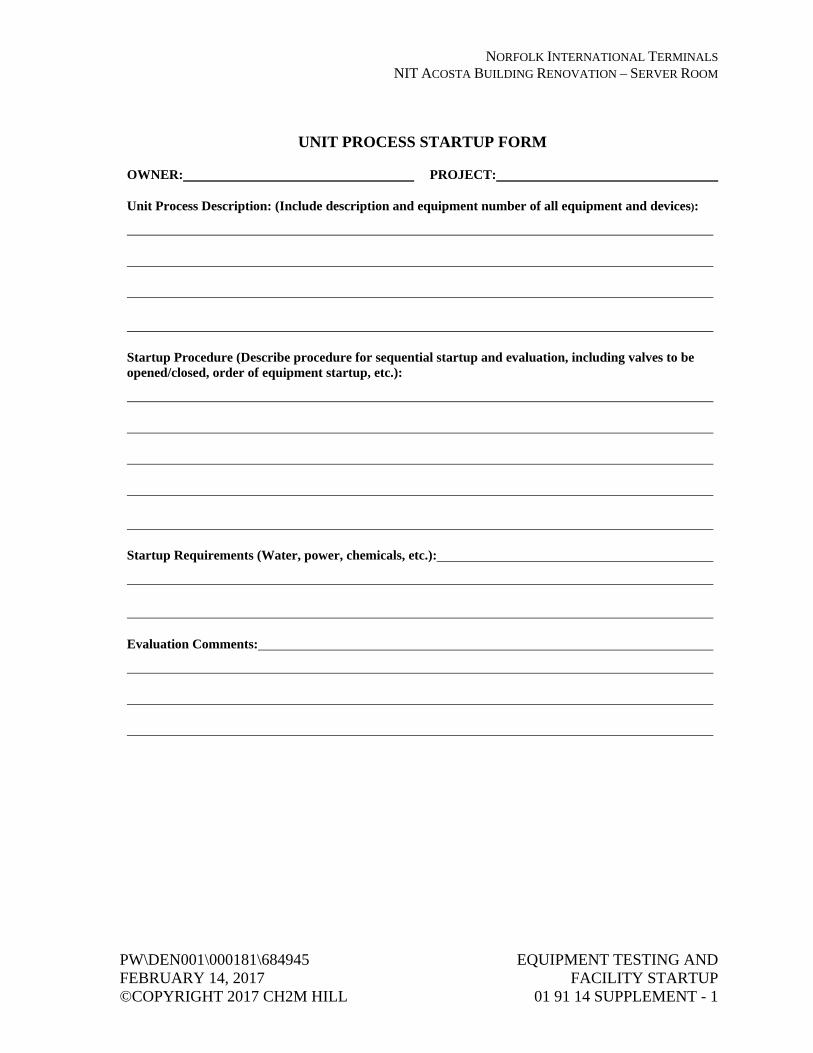
NORFOLK INTERNATIONAL TERMINALS NIT ACOSTA BUILDING RENOVATION – SERVER ROOM
PW\DEN001\000181\684945 EQUIPMENT TESTING AND FEBRUARY 14, 2017 FACILITY STARTUP ©COPYRIGHT 2017 CH2M HILL 01 91 14 SUPPLEMENT - 1
UNIT PROCESS STARTUP FORM
OWNER: PROJECT:
Unit Process Description: (Include description and equipment number of all equipment and devices):
Startup Procedure (Describe procedure for sequential startup and evaluation, including valves to be opened/closed, order of equipment startup, etc.):
Startup Requirements (Water, power, chemicals, etc.):
Evaluation Comments:


NORFOLK INTERNATIONAL TERMINALS NIT ACOSTA BUILDING RENOVATION – SERVER ROOM
PW\DEN001\000181\684945 EQUIPMENT TESTING FEBRUARY 14, 2017 AND FACILITY STARTUP ©COPYRIGHT 2017 CH2M HILL 01 91 14 SUPPLEMENT - 1
FACILITY PERFORMANCE DEMONSTRATION/CERTIFICATION FORM
OWNER: PROJECT:
Unit Processes Description (List unit processes involved in facility startup):
Unit Processes Startup Sequence (Describe sequence for startup, including computerized operations, if any):
Contractor Certification that Facility is capable of performing its intended function(s), including fully automatic operation:
Contractor: Date: _________________________, 20____
Engineer: (Authorized Signature)
Date: _________________________, 20____


NORFOLK INTERNATIONAL TERMINALS NIT ACOSTA BUILDING RENOVATION – SERVER ROOM
PW\DEN001\000181\684945 DEMOLITION FEBRUARY 14, 2017 02 41 00 - 1 ©COPYRIGHT 2017 CH2M HILL
SECTION 02 41 00 DEMOLITION
PART 1 GENERAL
1.01 REFERENCES
A. The following is a list of standards which may be referenced in this section:
1. American National Standards Institute (ANSI): A10.6, Safety Requirements for Demolition Operations.
2. Occupational Safety and Health Administration (OSHA), U.S. Code of Federal Regulations (CFR) Title 29 Part 1926—Occupational Safety and Health Regulations for Construction.
3. Environmental Protection Agency (EPA), U.S. Code of Federal Regulations (CFR), Title 40: a. Part 61—National Emission Standards for Hazardous Air
Pollutants. b. Part 82—Protection of Stratospheric Ozone. c. Part 273—Standards for Universal Waste Management.
1.02 DEFINITIONS
A. ACM: Asbestos-containing material.
B. Demolition: Dismantling, razing, destroying, or wrecking of any fixed building or structure or any part thereof.
C. Modify: Provide all necessary material and labor to modify an existing item to the condition indicated or specified.
D. Relocate: Remove, protect, clean and reinstall equipment, including electrical, instrumentation, and all ancillary components required to make the equipment fully functional, to the new location identified on the Drawings.
E. Renovation: Altering a facility or one or more facility components in any way.
F. Salvage/Salvageable: Remove and deliver, to the specified location(s), the equipment, building materials, or other items so identified to be saved from destruction, damage, or waste; such property to remain that of Owner. Unless otherwise specified, title to items identified for demolition shall revert to Contractor.
G. Universal Waste Lamp: In accordance with 40 CFR 273, the bulb or tube portion of an electric lighting device, examples of which include, but are not

NORFOLK INTERNATIONAL TERMINALS NIT ACOSTA BUILDING RENOVATION – SERVER ROOM
DEMOLITION PW\DEN001\000181\684945 02 41 00 - 2 FEBRUARY 14, 2017 ©COPYRIGHT 2017 CH2M HILL
limited to, fluorescent, high-intensity discharge, neon, mercury vapor, high-pressure sodium, and metal halide lamps.
H. Universal Waste Thermostat: A temperature control device that contains metallic mercury in an ampule attached to a bimetal sensing element, and mercury-containing ampules that have been removed from these temperature control devices in compliance with the requirements of 40 CFR 273.
1.03 SUBMITTALS
A. Informational Submittals:
1. Submit proposed demolition/renovation plan, in accordance with requirements specified herein, for approval before such Work is started.
2. Submit copies of any notifications, authorizations and permits required to perform the Work.
1.04 REGULATORY AND SAFETY REQUIREMENTS
A. When applicable, demolition Work shall be accomplished in strict accordance with 29 CFR 1926-Subpart T.
B. Comply with federal, state, and local hauling and disposal regulations. In addition to the requirements of the General Conditions, Contractor’s safety requirements shall conform to ANSI A10.6.
C. Furnish timely notification of this project to applicable federal, state, regional, and local authorities in accordance with 40 CFR 61-Subpart M.
1.05 DEMOLITION/RENOVATION PLAN
A. Demolition/renovation plan shall provide for safe conduct of the Work and shall include:
1. Detailed description of methods and equipment to be used for each operation;
2. The Contractor’s planned sequence of operations, including coordination with other work in progress;
3. Procedures for removal and disposition of materials specified to be salvaged.
B. Include statements affirming Contractor inspection of the framing members, and their suitability to perform as a safe working platform or, if inspection reveals a safety hazard to workers, state provisions for securing the safety of the workers throughout the performance of the Work.

NORFOLK INTERNATIONAL TERMINALS NIT ACOSTA BUILDING RENOVATION – SERVER ROOM
PW\DEN001\000181\684945 DEMOLITION FEBRUARY 14, 2017 02 41 00 - 3 ©COPYRIGHT 2017 CH2M HILL
1.06 SEQUENCING AND SCHEDULING
A. The Work of this Specification shall not commence until Contractor’s Demolition/Renovation Plan has been approved by Engineer.
B. Include the Work of this Specification in the progress schedule, as specified in Section 01 32 00, Construction Progress Documentation.
PART 2 PRODUCTS (NOT USED)
PART 3 EXECUTION
3.01 EXISTING FACILITIES TO BE DEMOLISHED OR RENOVATED
A. Facilities: Portions of buildings and other areas scheduled for selective demolition, partial demolition, and renovation Work are as shown.
B. Structures: Sidewalks, curbs, gutters and street light bases shall be removed as indicated.
C. Paving and Slabs:
1. Sawcut concrete and asphaltic concrete paving and slabs as indicated. 2. Provide neat sawcuts at limits of pavement removal as indicated.
D. Concrete: Saw concrete along straight lines to a depth of not less than 2 inches, or as indicated. Make each cut in walls perpendicular to the face and in alignment with the cut in the opposite face. Break out the remainder of the concrete provided that the broken area is concealed in the finished Work, and the remaining concrete is sound. At locations where the broken face cannot be concealed, grind smooth or saw cut entirely through the concrete. Where new concrete adjoins existing, the new Work shall abut or tie into the existing construction as specified.
E. Patching:
1. Where removals leave holes and damaged surfaces exposed in the finished Work, patch and repair to match adjacent finished surfaces as to texture and finish.
2. Where new Work is to be applied to existing surfaces, perform removals and patching in a manner to produce surfaces suitable for receiving new Work.

NORFOLK INTERNATIONAL TERMINALS NIT ACOSTA BUILDING RENOVATION – SERVER ROOM
DEMOLITION PW\DEN001\000181\684945 02 41 00 - 4 FEBRUARY 14, 2017 ©COPYRIGHT 2017 CH2M HILL
F. Electrical:
1. Cut off concealed or embedded conduit, boxes, or other materials a minimum of 3/4 inch below final finished surface.
2. When removing designated equipment, conduit and wiring may require rework to maintain service to other equipment.
3. Rework existing circuits, or provide temporary circuits as necessary during renovation to maintain service to existing lighting and equipment not scheduled to be renovated. Existing equipment and circuiting shown are based upon limited field surveys. Verify existing conditions, make all necessary adjustments, and record the Work on the Record Drawings. This shall include, but is not limited to, swapping and other adjustments to branch circuits and relocation of branch circuit breakers within panelboards as required to accomplish the finished work.
4. Reuse of existing luminaires, devices, conduits, boxes, or equipment will be permitted only where specifically indicated.
5. Raceways and cabling not scheduled for reuse. 6. Inaccessibly Concealed: Cut off and abandon in place. 7. Exposed or Concealed Above Accessible Ceilings: Remove. 8. Raceways and Cabling Scheduled for Future Use: Cap/seal and tag. 9. Relocating Equipment: Extend existing wiring or run new wiring from
the source. 10. Where the existing raceway is concealed, the outlet box shall be
cleaned, and a blank cover plate installed. 11. Where the concealed raceway is uncovered remove raceway (or
extended to new location if appropriate). 12. Provide new typewritten panelboard circuit directory cards.
G. Universal Waste Lamps and Thermostats: Manage, contain, package, and label in strict accordance with 40 CFR 273.
3.02 PROTECTION
A. Existing Work:
1. Survey the site and examine the Drawings and Specifications to determine the extent of the Work before beginning any demolition or renovation.
2. Take necessary precautions to avoid damage to existing items scheduled to remain in place, to be reused, or to remain the property of Owner; any Contractor-damaged items shall be repaired or replaced as directed by Engineer.
3. Do not overload pavements to remain.

NORFOLK INTERNATIONAL TERMINALS NIT ACOSTA BUILDING RENOVATION – SERVER ROOM
PW\DEN001\000181\684945 DEMOLITION FEBRUARY 14, 2017 02 41 00 - 5 ©COPYRIGHT 2017 CH2M HILL
B. Facilities:
1. Protect electrical and mechanical services and utilities. Where removal of existing utilities and pavement is specified or indicated, provide approved barricades, temporary covering of exposed areas, and temporary services or connections for electrical and mechanical utilities.
2. Protect all facility elements not scheduled for demolition. 3. Provide interior shoring, bracing, or support to prevent movement,
settlement, or collapse of structure or element to be demolished and adjacent facilities.
C. Protection of Personnel:
1. During demolition, continuously evaluate the condition of the structure being demolished and take immediate action to protect all personnel working in and around the demolition site.
2. Provide temporary barricades and other forms of protection to protect Owner’s personnel and the general public from injury due to demolition Work.
3. Provide protective measures as required to provide free and safe passage of Owner’s personnel and the general public to occupied portions of the structure.
3.03 TITLE TO MATERIALS
A. All salvaged equipment and materials will remain the property of Owner.
3.04 DISPOSITION OF MATERIAL
A. Do not remove equipment and materials without approval of Contractor’s Demolition/Renovation Plan by Engineer.
B. Salvage equipment to the maximum extent possible.
3.05 ACM
A. If ACM is discovered, notify Owner immediately. Use best practices for protecting the area until direction is provided.

NORFOLK INTERNATIONAL TERMINALS NIT ACOSTA BUILDING RENOVATION – SERVER ROOM
DEMOLITION PW\DEN001\000181\684945 02 41 00 - 6 FEBRUARY 14, 2017 ©COPYRIGHT 2017 CH2M HILL
3.06 CLEANUP
A. Debris and rubbish shall be removed from basement and similar excavations. Debris and rubbish shall be removed and transported in a manner that prevents spillage on streets or adjacent areas. Local regulations regarding hauling and disposal shall apply.
END OF SECTION

NORFOLK INTERNATIONAL TERMINALS NIT ACOSTA BUILDING RENOVATION – SERVER ROOM
PW\DEN001\000181\684945 BASIC ELECTRICAL REQUIREMENTS FEBRUARY 14, 2017 26 05 02 - 1 ©COPYRIGHT 2017 CH2M HILL
SECTION 26 05 02 BASIC ELECTRICAL REQUIREMENTS
PART 1 GENERAL
1.01 RELATED SECTIONS
A. Requirements specified within this section apply to Division 26, Electrical. Work specified herein shall be performed as if specified in the individual sections.
1.02 REFERENCES
A. The following is a list of standards which may be referenced in this section:
1. National Electrical Contractors Association (NECA): National Electrical Installation Standards.
2. National Electrical Manufacturers Association (NEMA): a. 250, Enclosures for Electrical Equipment (1000 Volts Maximum). b. Z535.4, Product Safety Signs and Labels.
3. National Fire Protection Association (NFPA): 70, National Electrical Code (NEC).
4. Underwriters Laboratories, Inc. (UL).
1.03 ELECTRIC SERVICE DIVISION OF RESPONSIBILITY
A. Incoming underground electrical service facilities provided by the serving utility as part of its normal obligation to customers is work provided outside this Contract. Duct bank and conduit from existing utility service point to the new utility pad-mounted transformer and also from new utility transformer to the new metering cabinet as shown on drawings shall be sized by the utility. Under this contract install referenced duct banks. Feeder conductors associated with these duct banks will be provided and installed by the utility. Under this Contract provide customer required service provisions and electrical work including, but not limited to, the metering cabinet, CTs, PTs components, associated conduit, and secondary facilities. Schedule and coordinate work of serving utility as required to provide electric service to the Work.

NORFOLK INTERNATIONAL TERMINALS NIT ACOSTA BUILDING RENOVATION – SERVER ROOM
BASIC ELECTRICAL REQUIREMENTS PW\DEN001\000181\684945 26 05 02 - 2 FEBRUARY 14, 2017 ©COPYRIGHT 2017 CH2M HILL
1.04 SUBMITTALS
A. Action Submittals:
1. Provide manufacturers’ data for the following: a. Nameplates, signs, and labels.
1.05 QUALITY ASSURANCE
A. Provide the Work in accordance with NFPA 70. Where required by authority having jurisdiction (AHJ), material and equipment shall be labeled or listed by a nationally recognized testing laboratory or other organization acceptable to the AHJ, in order to provide a basis for approval under the NEC.
B. Materials and equipment manufactured within the scope of standards published by Underwriters Laboratories Inc. (UL) shall conform to those standards and shall have an applied UL listing mark or label.
C. Provide materials and equipment acceptable to AHJ for Class, Division, and Group of hazardous area indicated.
1.06 ENVIRONMENTAL CONDITIONS
A. The following areas are classified hazardous Class I, Division 1, Group D, due to the potential for occurrence of hazardous concentrations of combustible gases, and for exposure to corrosive environment. Use materials and methods required for such areas.
1. Inside wet well containing wastewater, 300.
B. The following areas are classified as finished, indoor, dry for the purpose of Division 26, Electrical:
1. Electrical room, 101. 2. Entry room, 100.
C. The following area is classified as finished, indoor, damp for the purpose of Division 26, Electrical:
1. Dry well/pump room, 301.
D. All outdoor areas not listed above are classified as outdoor, wet, and corrosive for the purpose of Division 26, Electrical.

NORFOLK INTERNATIONAL TERMINALS NIT ACOSTA BUILDING RENOVATION – SERVER ROOM
PW\DEN001\000181\684945 BASIC ELECTRICAL REQUIREMENTS FEBRUARY 14, 2017 26 05 02 - 3 ©COPYRIGHT 2017 CH2M HILL
PART 2 PRODUCTS
2.01 GENERAL
A. Where two or more units of the same class of material or equipment are required, provide products of a single manufacturer. Component parts of materials or equipment need not be products of the same manufacturer.
B. Material and equipment installed in heated and ventilated areas shall be capable of continuous operation at their specified ratings within an ambient temperature range of 40 to 104 degrees F.
C. Materials and equipment installed outdoors shall be capable of continuous operation at their specified rating within the ambient temperature range stated in Section 01 61 00, Common Product Requirements.
2.02 EQUIPMENT FINISH
A. Manufacturer’s standard finish color, except where specific color is indicated. If manufacturer has no standard color, finish equipment in light gray color finish as approved by Owner.
2.03 NAMEPLATES
A. Material: Laminated plastic.
B. Attachment Screws: Stainless steel.
C. Color: White, engraved to a black core.
D. Letter Height:
1. Pushbuttons/Selector Switches: 1/8 inch. 2. Other Electrical Equipment: 1/4 inch.
2.04 SIGNS AND LABELS
A. Sign size, lettering, and color shall be in accordance with NEMA Z535.4.
PART 3 EXECUTION
3.01 GENERAL
A. Electrical Drawings show general locations of equipment, devices, and raceway, unless specifically dimensioned. Contractor shall be responsible for

NORFOLK INTERNATIONAL TERMINALS NIT ACOSTA BUILDING RENOVATION – SERVER ROOM
BASIC ELECTRICAL REQUIREMENTS PW\DEN001\000181\684945 26 05 02 - 4 FEBRUARY 14, 2017 ©COPYRIGHT 2017 CH2M HILL
actual location of equipment and devices and for proper routing and support of raceways, subject to approval of Engineer.
B. Check approximate locations of light fixtures, switches, electrical outlets, equipment, and other electrical system components shown on Drawings for conflicts with openings, structural members, and components of other systems and equipment having fixed locations. In the event of conflicts, notify Engineer in writing.
C. Install work in accordance with NECA Standard of Installation, unless otherwise specified.
D. Keep openings in boxes and equipment closed during construction.
E. Lay out work carefully in advance. Do not cut or notch any structural member or building surface without specific approval of Engineer. Carefully perform cutting, channeling, chasing, or drilling of floors, walls, partitions, ceilings, paving, or other surfaces required for the installation, support, or anchorage of conduit, raceways, or other electrical materials and equipment. Following such work, restore surfaces to original condition.
3.02 ANCHORING AND MOUNTING
A. Equipment anchoring and mounting shall be in accordance with manufacturer’s requirements for seismic zone criteria given in Section 01 61 00, Common Product Requirements.
3.03 COMBINING CIRCUITS INTO COMMON RACEWAY
A. Homerun circuits shown on Drawings indicate functional wiring requirements for power and control circuits. Circuits may be combined into common raceways in accordance with the following requirements:
1. Analog control circuits from devices in same general area to same destination. a. No power or ac discrete control circuits shall be combined in same
conduit with analog circuits. b. No Class 2 or Class 3 circuits including, but not limited to, HVAC
control circuits, fire alarm circuits, paging system circuits shall be combined with power or Class 1 circuits.
c. Analog circuits shall be continuous from source to destination. Do not add TJB, splice, or combine into a multi-pair cable without authorization of Engineer.

NORFOLK INTERNATIONAL TERMINALS NIT ACOSTA BUILDING RENOVATION – SERVER ROOM
PW\DEN001\000181\684945 BASIC ELECTRICAL REQUIREMENTS FEBRUARY 14, 2017 26 05 02 - 5 ©COPYRIGHT 2017 CH2M HILL
d. Raceways shall be sized in accordance with General Circuit and Raceway Schedule and do not exceed 40 percent fill.
e. Changes shall be documented on record drawings. 2. Discrete control circuits from devices in the same general area to the
same destination. a. No power or analog control circuits shall be combined in same
conduit with discrete circuits. b. No Class 2 or Class 3 circuits including, but not limited to, HVAC
control circuits, fire alarm circuits, and paging system circuits shall be combined with power or Class 1 circuits.
c. Raceways shall be sized according to the General Circuit and Raceway Schedule and do not exceed 40 percent fill.
d. Changes shall be documented on record drawings. 3. Power circuits from loads in same general area to same source location
(such as: panelboard, switchboard, low voltage motor control center). a. Lighting Circuits: Combine no more than three circuits to a single
raceway. Contractor shall be responsible for increasing conduit and conductor size if derating is required by NEC.
b. Receptacle Circuits, 120-Volt Only: Combine no more than three circuits to a single raceway. Provide a separate neutral conductor for each circuit. Contractor shall be responsible for increasing conduit and conductor size if derating is required by NEC.
c. All Other Power Circuits: Do not combine power circuits without authorization of Engineer.
3.04 NAMEPLATES, SIGNS, AND LABELS
A. Arc Flash Protection Warning Signs:
1. Field mark main circuit breakers, automatic transfer switch, motor control centers, AFDs, panelboards, dry transformer, disconnect switches, sump pump control panel, comminutor control panel to warn qualified persons of potential arc-flash hazards. Locate marking so to be clearly visible to persons before working on energized equipment.
2. Use arc flash hazard boundary, energy level, PPE level and description, shock hazard, bolted fault current, and equipment name from study required in Section 26 05 70, Electrical Systems Analysis, from Engineer as basis for warning signs.
B. Equipment Nameplates:
1. Provide a nameplate to label electrical equipment including switchgear, switchboards, motor control centers, panelboards, motor starters,

NORFOLK INTERNATIONAL TERMINALS NIT ACOSTA BUILDING RENOVATION – SERVER ROOM
BASIC ELECTRICAL REQUIREMENTS PW\DEN001\000181\684945 26 05 02 - 6 FEBRUARY 14, 2017 ©COPYRIGHT 2017 CH2M HILL
transformers, terminal junction boxes, disconnect switches, switches and control stations.
2. Switchgear, motor control center, transformer, and terminal junction box nameplates shall include equipment designation.
3. Disconnect switch, starter, and control station nameplates shall include name and number of equipment powered or controlled by that device.
4. Main circuit breakers, motor control center, and panelboard nameplates shall include equipment designation, service voltage, and phases.
3.05 LOAD BALANCE
A. Drawings and Specifications indicate circuiting to electrical loads and distribution equipment.
B. Balance electrical load between phases as nearly as possible on switchboards, panelboards, motor control centers, and other equipment where balancing is required.
C. When loads must be reconnected to different circuits to balance phase loads, maintain accurate record of changes made, and provide circuit directory that lists final circuit arrangement.
3.06 CLEANING AND TOUCHUP PAINTING
A. Cleaning: Throughout the Work, clean interior and exterior of devices and equipment by removing debris and vacuuming.
B. Touchup Paint:
1. Touchup scratches, scrapes and chips on exterior and interior surfaces of devices and equipment with finish matching type, color, and consistency and type of surface of original finish.
2. If extensive damage is done to equipment paint surfaces, refinish entire equipment in a manner that provides a finish equal to or better than factory finish, that meets requirements of Specification, and is acceptable to Engineer.
3.07 PROTECTION FOLLOWING INSTALLATION
A. Protect materials and equipment from corrosion, physical damage, and effects of moisture on insulation and contact surfaces.

NORFOLK INTERNATIONAL TERMINALS NIT ACOSTA BUILDING RENOVATION – SERVER ROOM
PW\DEN001\000181\684945 BASIC ELECTRICAL REQUIREMENTS FEBRUARY 14, 2017 26 05 02 - 7 ©COPYRIGHT 2017 CH2M HILL
B. When equipment intended for indoor installation is installed at Contractor’s convenience in areas where subject to dampness, moisture, dirt or other adverse atmosphere until completion of construction, ensure adequate protection from these atmospheres is provided and acceptable to Engineer.
END OF SECTION


NORFOLK INTERNATIONAL TERMINALS NIT ACOSTA BUILDING RENOVATION – SERVER ROOM
PW\DEN001\000181\684945 BASIC ELECTRICAL MATERIALS FEBRUARY 14, 2017 AND METHODS ©COPYRIGHT 2017 CH2M HILL 26 05 04 - 1
SECTION 26 05 04 BASIC ELECTRICAL MATERIALS AND METHODS
PART 1 GENERAL
1.01 REFERENCES
A. The following is a list of standards which may be referenced in this section:
1. ASTM International (ASTM): a. A167, Standard Specification for Stainless and Heat-Resisting
Chromium-Nickel Steel Plate, Sheet, and Strip. b. A1011/A1011M, Standard Specification for Steel, Sheet, and
Strip, Hot-Rolled, Carbon, Structural, High-Strength Low Alloy and High-Strength Low Alloy Formability.
c. E814, Method of Fire Tests of Through-Penetration Fire Stops. 2. Canadian Standards Association (CSA). 3. Institute of Electrical and Electronics Engineers, Inc. (IEEE): 18,
Standard for Shunt Power Capacitors. 4. International Society of Automation (ISA): RP12.06.01, Wiring
Practices for Hazardous (Classified) Locations Instrumentation–Part 1: Intrinsic Safety.
5. National Electrical Manufacturers Association (NEMA): a. 250, Enclosures for Electrical Equipment (1,000 Volts
Maximum). b. AB 1, Molded Case Circuit Breakers, Molded Case Switches, and
Circuit-Breaker Enclosures. c. C12.1 Code for Electricity Metering d. C12.6 Phase-Shifting Devices Used in Metering, Marking and
Arrangement of, Terminals for e. CP 1, Shunt Capacitors. f. ICS 2, Industrial Control and Systems: Controllers, Contactors,
and Overload Relays Rated 600 Volts. g. ICS 5, Industrial Control and Systems: Control Circuit and Pilot
Devices. h. KS 1, Enclosed and Miscellaneous Distribution Switches
(600 Volts Maximum). 6. National Fire Protection Association (NFPA): 70, National Electrical
Code (NEC). 7. Underwriters Laboratories Inc. (UL):
a. 98, Standard for Enclosed and Dead-Front Switches. b. 248, Standard for Low Voltage Fuses.

NORFOLK INTERNATIONAL TERMINALS NIT ACOSTA BUILDING RENOVATION – SERVER ROOM
BASIC ELECTRICAL MATERIALS PW\DEN001\000181\684945 AND METHODS FEBRUARY 14, 2017 26 05 04 - 2 ©COPYRIGHT 2017 CH2M HILL
c. 486E, Standard for Equipment Wiring Terminals for use with Aluminum and/or Copper Conductors.
d. 489, Standard for Molded-Case Circuit Breakers, Molded-Case Switches, and Circuit Breaker Enclosures.
e. 508, Standard for Industrial Control Equipment. f. 810, Standard for Capacitors. g. 943, Standard for Ground-Fault Circuit-Interrupters. h. 1059, Standard for Terminal Blocks. i. 1479, Fire Tests of Through-Penetration Fire Stops.
1.02 SUBMITTALS
A. Action Submittals:
1. Provide manufacturers’ data for the following: a. Control devices. b. Control relays. c. Circuit breakers. d. Fused switches. e. Nonfused switches. f. Timers. g. Fuses. h. Magnetic contactors. i. Intrinsic safety barriers. j. Firestopping. k. Enclosures: Include enclosure data for products having
enclosures.
1.03 EXTRA MATERIALS
A. Furnish, tag, and box for shipment and storage the following spare parts and special tools:
1. Fuses, 0 to 600 Volts: Six of each type and each current rating installed.
PART 2 PRODUCTS
2.01 MOLDED CASE CIRCUIT BREAKER THERMAL MAGNETIC, LOW VOLTAGE
A. General:
1. Type: Molded case. 2. Trip Ratings: 500 amps as shown. 3. Voltage Ratings: 480 ac, three-phase.

NORFOLK INTERNATIONAL TERMINALS NIT ACOSTA BUILDING RENOVATION – SERVER ROOM
PW\DEN001\000181\684945 BASIC ELECTRICAL MATERIALS FEBRUARY 14, 2017 AND METHODS ©COPYRIGHT 2017 CH2M HILL 26 05 04 - 3
4. Suitable for mounting and operating in any position. 5. NEMA AB 1 and UL 489. 6. UL labeled as suitable for service entrance where shown on drawings. 7. Short Circuit Interrupting Rating: 65,000 amperes rms symmetrical at
480 volts.
B. Operating Mechanism:
1. Overcenter, trip-free, toggle type handle. 2. Quick-make, quick-break action. 3. Locking provisions for padlocking breaker in open position. 4. ON/OFF and TRIPPED indicating positions of operating handle. 5. Operating handle to assume a center position when tripped.
C. Protective Device:
1. Incoming Service Feeder: Cable. 2. Solid State Trip Circuit Breaker:
a. In accordance with UL 489. b. Molded case breakers with ambient insensitive solid-state trips
and having current sensors and logic circuits integral in breaker frame.
c. Solid-state current control with adjustable ampere setting, adjustable long-time delay, adjustable short-time trip and delay band, fixed or adjustable instantaneous trip.
d. Setting adjustments to be covered by a sealable, tamper-proof, transparent cover (insulated case breakers only) or by compartment door (for other breakers).
e. Locate trip button on front cover of breaker to permit mechanical simulation overcurrent tripping for test purposes and to trip breaker quickly in emergency situation.
f. Indicate tripping by operating-handle position. g. Suitable for use with 75 degrees C wire at full NEC 75 degrees C
ampacity.
D. Digital Power Meter (DPM):
1. General: a. Solid state device with LED displays. b. Direct voltage input up to 600V ac. c. Current input via current transformer with 5-ampere secondary. d. Programmable current and potential transformer ratios. e. Programmable limits to activate up to four alarms. f. Selectable Voltage Measurements: Line-to-line or line-to-neutral
and wye or delta.

NORFOLK INTERNATIONAL TERMINALS NIT ACOSTA BUILDING RENOVATION – SERVER ROOM
BASIC ELECTRICAL MATERIALS PW\DEN001\000181\684945 AND METHODS FEBRUARY 14, 2017 26 05 04 - 4 ©COPYRIGHT 2017 CH2M HILL
2. Simultaneous Display: a. Volts, three-phase. b. Amperes, three-phase. c. Kilowatts. d. Kilowatt hours. e. Frequency.
3. Manufacturers and Products: a. Allen Bradley; Model 1400 Series. b. Eaton; IQ DP-4000.
E. Connections:
1. Supply (line side) at either end. 2. Mechanical wire lugs, except crimp compression lugs where shown. 3. Lugs removable/replaceable for breaker frames greater than 100 amperes. 4. Suitable for 75 degrees C rated conductors without derating breaker or
conductor ampacity.
F. Enclosures for Independent Mounting:
1. Freestanding, NEMA 12, steel. 2. Service Entrance Use: Breakers in required enclosure and required
accessories shall be UL 489 listed. 3. Interlock: Enclosure and switch shall interlock to prevent opening cover
with switch in the ON position. Provide bypass feature for use by qualified personnel.
G. Nameplates:
1. Laminated plastic; white, engraved to black core. 2. Provide for each circuit breaker. 3. Engrave with inscription shown on single-line diagram. 4. Provide blank nameplates on spaces for future units. 5. Attach with stainless steel panhead screws on face of breaker.
H. Manufacturers:
1. Unless otherwise noted, materials, equipment, and accessories specified in this section shall be product of: a. Eaton Electrical/Cutler-Hammer. b. GE Industrial Systems. c. Schneider Electric/Square-D.

NORFOLK INTERNATIONAL TERMINALS NIT ACOSTA BUILDING RENOVATION – SERVER ROOM
PW\DEN001\000181\684945 BASIC ELECTRICAL MATERIALS FEBRUARY 14, 2017 AND METHODS ©COPYRIGHT 2017 CH2M HILL 26 05 04 - 5
2.02 PUSHBUTTON, INDICATING LIGHT, AND SELECTOR SWITCH
A. Contact Rating: 7,200VA make, 720VA break, at 600V, NEMA ICS 5 Designation A600.
B. Selector Switch Operating Lever: Standard.
C. Indicating Light: Push-to-test, transformer-type.
D. Pushbutton Color:
1. ON or START: Black. 2. OFF or STOP: Red.
E. Pushbutton and selector switch lockable in OFF position where indicated.
F. Legend Plate:
1. Material: Aluminum. 2. Engraving: Enamel filled in high contrasting color. 3. Text Arrangement: 11-character/spaces on one line, 14-character/spaces
on each of two lines, as required, indicating specific function. 4. Letter Height: 7/64-inch.
G. Manufacturers and Products:
1. Heavy-Duty, Oil-Tight Type: a. General Electric Co.; Type CR 104P. b. Square D Co.; Type T. c. Eaton/Cutler-Hammer; Type 10250T.
2. Heavy-Duty, Watertight, and Corrosion-Resistant Type: a. Square D Co.; Type SK. b. General Electric Co.; Type CR 104P. c. Eaton/Cutler-Hammer; Type E34. d. Crouse-Hinds; Type NCS.
2.03 TERMINAL BLOCK, 600 VOLTS
A. UL 486E and UL 1059.
B. Size components to allow insertion of necessary wire sizes.
C. Capable of termination of control circuits entering or leaving equipment, panels, or boxes.

NORFOLK INTERNATIONAL TERMINALS NIT ACOSTA BUILDING RENOVATION – SERVER ROOM
BASIC ELECTRICAL MATERIALS PW\DEN001\000181\684945 AND METHODS FEBRUARY 14, 2017 26 05 04 - 6 ©COPYRIGHT 2017 CH2M HILL
D. Screw clamp compression, dead front barrier type, with current bar providing direct contact with wire between compression screw and yoke.
E. Yoke, current bar, and clamping screw of high strength and high conductivity metal.
F. Yoke shall guide all strands of wire into terminal.
G. Current bar shall ensure vibration-proof connection.
H. Terminals:
1. Capable of wire connections without special preparation other than stripping.
2. Capable of jumper installation with no loss of terminal or rail space. 3. Individual, rail mounted.
I. Marking system, allowing use of preprinted or field-marked tags.
J. Manufacturers:
1. Weidmuller, Inc. 2. Ideal. 3. Electrovert USA Corp.
2.04 MAGNETIC CONTROL RELAY
A. Industrial control with field convertible contacts rated 10 amps continuous, 7,200VA make, 720VA break.
B. NEMA ICS 2, Designation: A600 (600 volts).
C. Time Delay Relay Attachment:
1. Pneumatic type, timer adjustable from 0.2 second to 60 seconds (minimum) as shown.
2. Field convertible from ON delay to OFF delay and vice versa.
D. Latching Attachment: Mechanical latch, having unlatching coil and coil clearing contacts.
E. Manufacturers and Products:
1. Eaton/Cutler-Hammer; Type M-600. 2. General Electric Co.; Type CR120B.

NORFOLK INTERNATIONAL TERMINALS NIT ACOSTA BUILDING RENOVATION – SERVER ROOM
PW\DEN001\000181\684945 BASIC ELECTRICAL MATERIALS FEBRUARY 14, 2017 AND METHODS ©COPYRIGHT 2017 CH2M HILL 26 05 04 - 7
2.05 TIME DELAY RELAY
A. Industrial relay with contacts rated 5 amps continuous, 3,600VA make, 360VA break.
B. NEMA ICS 2 Designation: B150 (150 volts).
C. Solid-state electronic, field convertible ON/OFF delay.
D. One normally open and one normally closed contact (minimum).
E. Repeat accuracy plus or minus 2 percent.
F. Timer adjustment from 1 second to 60 seconds, unless otherwise indicated on Drawings.
G. Manufacturers and Products:
1. Square D Co.; Type F. 2. Eaton/Cutler-Hammer. 3. General Electric Co.
2.06 SUPPORT AND FRAMING CHANNELS
A. Carbon Steel Framing Channel:
1. Material: Rolled, mild strip steel, 12-gauge minimum, ASTM A1011/A1011M, Grade 33.
2. Finish: Hot-dip galvanized after fabrication.
B. Paint Coated Framing Channel: Carbon steel framing channel with electro-deposited rust inhibiting acrylic or epoxy paint.
C. PVC Coated Framing Channel: Carbon steel framing channel with 40-mil polyvinyl chloride coating.
D. Stainless Steel Framing Channel: Rolled, ASTM A167, Type 316 stainless steel, 12-gauge minimum.
E. Extruded Aluminum Framing Channel:
1. Material: Extruded from Type 6063-T6 aluminum alloy. 2. Fittings fabricated from Alloy 5052-H32.

NORFOLK INTERNATIONAL TERMINALS NIT ACOSTA BUILDING RENOVATION – SERVER ROOM
BASIC ELECTRICAL MATERIALS PW\DEN001\000181\684945 AND METHODS FEBRUARY 14, 2017 26 05 04 - 8 ©COPYRIGHT 2017 CH2M HILL
F. Nonmetallic Framing Channel:
1. Material: Fire retardant, fiber reinforced vinyl ester resin. 2. Channel fitting of same material as channel. 3. Nuts and bolts of long glass fiber reinforced polyurethane.
G. Manufacturers:
1. B-Line Systems, Inc. 2. Unistrut Corp. 3. Aickinstrut.
2.07 SWITCHBOARD MATTING
A. Provide matting having a breakdown of 20 kV minimum.
B. Manufacturer: U.S. Mat and Rubber Company.
2.08 FIRESTOPS
A. General:
1. Provide UL 1479 classified hourly fire-rating equal to, or greater than, the assembly penetrated.
2. Prevent the passage of cold smoke, toxic fumes, and water before and after exposure to flame.
3. Sealants and accessories shall have fire-resistance ratings as established by testing identical assemblies in accordance with ASTM E814, by UL, or other testing and inspection agency acceptable to authorities having jurisdiction.
2.09 ENCLOSURES
A. Finish: Sheet metal structural and enclosure parts shall be completely painted using an electrodeposition process so interior and exterior surfaces as well as bolted structural joints have a complete finish coat on and between them.
B. Color: Manufacturer’s standard color (gray) baked-on enamel, unless otherwise shown.
C. Barriers: Provide metal barriers within enclosures to separate wiring of different systems and voltage.

NORFOLK INTERNATIONAL TERMINALS NIT ACOSTA BUILDING RENOVATION – SERVER ROOM
PW\DEN001\000181\684945 BASIC ELECTRICAL MATERIALS FEBRUARY 14, 2017 AND METHODS ©COPYRIGHT 2017 CH2M HILL 26 05 04 - 9
D. Enclosure Selections: Except as shown otherwise, provide electrical enclosures according to the following table:
ENCLOSURES
Location Finish Environment NEMA 250 Type
Indoor Finished Dry 12
Indoor and outdoor Any Wet 4X, Type 316 stainless steel
PART 3 EXECUTION
3.01 GENERAL
A. Install equipment in accordance with manufacturer’s recommendations.
3.02 PUSHBUTTON, INDICATING LIGHT, AND SELECTOR SWITCH
A. Unless otherwise shown, install heavy-duty, oil-tight type in nonhazardous, indoor, dry locations, including motor control centers, control panels, and individual stations.
B. Unless otherwise shown, install heavy-duty, watertight and corrosion-resistant type in nonhazardous, outdoor, or normally wet areas.
3.03 SUPPORT AND FRAMING CHANNEL
A. Install where required for mounting and supporting electrical equipment, raceway, and cable tray systems.
B. Channel Type:
1. Interior, Wet or Dry (Noncorrosive) Locations: a. Aluminum Raceway: Extruded aluminum. b. PVC-Coated Conduit: PVC coated. c. Steel Raceway and Other Systems Not Covered: Carbon steel or
paint coated. 2. Interior, Corrosive (Wet or Dry) Locations:
a. Aluminum Raceway: Extruded aluminum. b. PVC Conduit: Type 316 stainless steel or nonmetallic. c. PVC-Coated Steel Conduit and Other Systems Not Covered:
Type 316 stainless steel, nonmetallic, or PVC-coated steel.
NORFOLK INTERNATIONAL TERMINALS NIT ACOSTA BUILDING RENOVATION – SERVER ROOM
BASIC ELECTRICAL MATERIALS PW\DEN001\000181\684945 AND METHODS FEBRUARY 14, 2017 26 05 04 - 10 ©COPYRIGHT 2017 CH2M HILL
3. Outdoor, Noncorrosive Locations: a. Steel Raceway: Carbon steel or paint coated framing channel,
except where mounted on aluminum handrail, then use aluminum framing channel.
b. Aluminum Raceway and Other Systems Not Covered: Aluminum framing channel.
4. Outdoor Corrosive Locations: a. PVC Conduit: Type 316 stainless steel or nonmetallic. b. Aluminum Raceway: Aluminum. c. PVC-Coated Steel Conduit and Other Systems Not Covered:
Type 316 stainless steel, nonmetallic, or PVC coated steel.
C. Paint cut ends prior to installation with the following:
1. Carbon Steel Channel: Zinc-rich primer. 2. Painted Channel: Rust-inhibiting epoxy or acrylic paint. 3. Nonmetallic Channel: Epoxy resin sealer. 4. PVC-Coated Channel: PVC patch.
3.04 SWITCHBOARD MATTING
A. Install 36-inch width at switchgear, switchboard, motor control centers, and panelboards.
B. Matting shall run full length of all sides of equipment that have operator controls or afford access to devices.
3.05 FIRESTOPS
A. Install in strict conformance with manufacturer’s instructions. Comply with installation requirements established by testing and inspecting agency.
B. Sealant: Install sealant, including forming, packing, and other accessory materials, to fill openings around electrical services penetrating floors and walls, to provide firestops with fire-resistance ratings indicated for floor or wall assembly in which penetration occurs.
END OF SECTION

NORFOLK INTERNATIONAL TERMINALS NIT ACOSTA BUILDING RENOVATION – SERVER ROOM
PW\DEN001\000181\684945 CONDUCTORS FEBRUARY 14, 2017 26 05 05 - 1 ©COPYRIGHT 2017 CH2M HILL
SECTION 26 05 05 CONDUCTORS
PART 1 GENERAL
1.01 REFERENCES
A. The following is a list of standards which may be referenced in this section:
1. Association of Edison Illuminating Companies (AEIC): CS 8, Specification for Extruded Dielectric Shielded Power Cables Rated 5 kV through 46 kV.
2. ASTM International (ASTM): a. A167, Standard Specification for Stainless and Heat-Resisting
Chromium-Nickel Steel Plate, Sheet, and Strip. b. B3, Standard Specification for Soft or Annealed Copper Wire. c. B8, Standard Specification for Concentric-Lay-Stranded Copper
Conductors, Hard, Medium-Hard, or Soft. d. B496, Standard Specification for Compact Round Concentric-
Lay-Stranded Copper Conductors. 3. Institute of Electrical and Electronics Engineers, Inc. (IEEE):
a. 48, Standard Test Procedures and Requirements for Alternating-Current Cable Terminations Used on Shielded Cables Having Laminated Insulation Rated 2.5 kV through 765 kV or Extruded Insulation Rated 2.5 kV Through 500 kV.
b. 386, Standard for Separable Insulated Connector Systems for Power Distribution Systems Above 600V.
c. 404, Standard for Extruded and Laminated Dielectric Shielded Cable Joints Rated 2500 V to 500000 V.
4. Insulated Cable Engineer’s Association, Inc. (ICEA): a. S-58-679, Standard for Control Cable Conductor Identification. b. S-73-532, Standard for Control Thermocouple Extensions and
Instrumentation Cables. c. T-29-520, Conducting Vertical Cable Tray Flame Tests with
Theoretical Heat Input of 210,000 Btu/hour. 5. National Electrical Manufacturers’ Association (NEMA):
a. CC 1, Electric Power Connectors for Substations. b. WC 57, Standard for Control, Thermocouple Extension, and
Instrumentation Cables. c. WC 70, Standard for Power Cables Rated 2000 Volts or Less for
the Distribution of Electrical Energy. d. WC 71, Standard for Nonshielded Cables Rated 2001-5000 Volts
for Use in the Distribution of Electric Energy.

NORFOLK INTERNATIONAL TERMINALS NIT ACOSTA BUILDING RENOVATION – SERVER ROOM
CONDUCTORS PW\DEN001\000181\684945 26 05 05 - 2 FEBRUARY 14, 2017 ©COPYRIGHT 2017 CH2M HILL
e. WC 74, 5-46 kV Shielded Power Cable for Use in the Transmission and Distribution of Electric Energy.
6. National Fire Protection Association (NFPA): a. 70, National Electrical Code (NEC). b. 262, Standard Method of Test for Flame Travel and Smoke of
Wires and Cables for Use in Air-Handling Spaces. 7. Telecommunications Industry Association (TIA): TIA-568-C,
Commercial Building Telecommunications Cabling Standard. 8. Underwriters Laboratories Inc. (UL):
a. 13, Standard for Safety for Power-Limited Circuit Cables. b. 44, Standard for Safety for Thermoset-Insulated Wires and
Cables. c. 62, Standard for Safety for Flexible Cord and Cables. d. 486A-486B, Standard for Safety for Wire Connectors. e. 486C, Standard for Safety for Splicing Wire Connectors. f. 510, Standard for Safety for Polyvinyl Chloride, Polyethylene,
and Rubber Insulating Tape. g. 854, Standard for Safety for Service-Entrance Cables. h. 1072, Standard for Safety for Medium-Voltage Power Cables. i. 1277, Standard for Safety for Electrical Power and Control Tray
Cables with Optional Optical-Fiber Members. j. 1569, Standard for Safety for Metal-Clad Cables. k. 1581, Standard for Safety for Reference Standard for Electrical
Wires, Cables, and Flexible Cords.
1.02 SUBMITTALS
A. Action Submittals:
1. Product Data: a. Wire and cable. b. Wire and cable accessories. c. Cable fault detection system.
2. Cable Pulling Calculations: a. Ensure submitted and reviewed before cable installation. b. Provide for the following cable installations:
1) Multiconductor 600-volt cable sizes larger than 2 AWG that cannot be hand pulled.
B. Informational Submittals:
1. Journeyman lineman or electrician splicing credentials. 2. Certified factory test report in accordance with AEIC CS 8, including
AEIC qualification report for conductors above 600 volts.
NORFOLK INTERNATIONAL TERMINALS NIT ACOSTA BUILDING RENOVATION – SERVER ROOM
PW\DEN001\000181\684945 CONDUCTORS FEBRUARY 14, 2017 26 05 05 - 3 ©COPYRIGHT 2017 CH2M HILL
1.03 QUALITY ASSURANCE
A. Authority Having Jurisdiction (AHJ):
1. Provide the Work in accordance with NFPA 70. Where required by the AHJ, material and equipment shall be labeled or listed by a nationally recognized testing laboratory or other organization acceptable to the AHJ in order to provide a basis for approval under NEC.
2. Materials and equipment manufactured within the scope of standards published by UL shall conform to those standards and shall have an applied UL listing mark.
PART 2 PRODUCTS
2.01 CONDUCTORS 600 VOLTS AND BELOW
A. Conform to applicable requirements of NEMA WC 70.
B. Conductor Type:
1. 120-Volt and 277-Volt Lighting, 10 AWG and Smaller: Solid copper. 2. 120-Volt Receptacle Circuits, 10 AWG and Smaller: Solid copper. 3. All Other Circuits: Stranded copper.
C. Insulation: Type THHN/THWN-2, except for sizes No. 6 and larger, with XHHW-2 insulation.
2.02 600-VOLT RATED CABLE
A. General:
1. Type TC, meeting requirements of UL 1277, including Vertical Tray Flame Test at 70,000 Btu per hour, and NFPA 70, Article 340, or UL 13 meeting requirements of NFPA 70, Article 725.
2. Permanently and legibly marked with manufacturer’s name, maximum working voltage for which cable was tested, type of cable, and UL listing mark.
3. Suitable for installation in open air, in cable trays, or conduit. 4. Minimum Temperature Rating: 90 degrees C dry locations,
75 degrees C wet locations. 5. Overall Outer Jacket: PVC, flame-retardant, sunlight- and oil-resistant.

NORFOLK INTERNATIONAL TERMINALS NIT ACOSTA BUILDING RENOVATION – SERVER ROOM
CONDUCTORS PW\DEN001\000181\684945 26 05 05 - 4 FEBRUARY 14, 2017 ©COPYRIGHT 2017 CH2M HILL
2.03 GROUNDING CONDUCTORS
A. Equipment: Stranded copper with green, Type USE/RHH/RHW-XLPE or THHN/THWN, insulation.
B. Direct Buried: Bare stranded copper.
2.04 ACCESSORIES FOR CONDUCTORS 600 VOLTS AND BELOW
A. Tape:
1. General Purpose, Flame Retardant: 7-mil, vinyl plastic, Scotch Brand 33+, rated for 90 degrees C minimum, meeting requirements of UL 510.
2. Flame Retardant, Cold and Weather Resistant: 8.5-mil, vinyl plastic, Scotch Brand 88.
3. Arc and Fireproofing: a. 30-mil, elastomer. b. Manufacturers and Products:
1) 3M; Scotch Brand 77, with Scotch Brand 69 glass cloth tapebinder.
2) Plymouth; 53 Plyarc, with 77 Plyglas glass cloth tapebinder.
B. Identification Devices:
1. Sleeve: a. Permanent, PVC, yellow or white, with legible machine-printed
black markings. b. Manufacturers and Products:
1) Raychem; Type D-SCE or ZH-SCE. 2) Brady, Type 3PS.
2. Heat Bond Marker: a. Transparent thermoplastic heat bonding film with acrylic pressure
sensitive adhesive. b. Self-laminating protective shield over text. c. Machine printed black text. d. Manufacturer and Product: 3M Co.; Type SCS-HB.
3. Marker Plate: Nylon, with legible designations permanently hot stamped on plate.
4. Tie-On Cable Marker Tags: a. Chemical-resistant white tag. b. Size: 1/2 inch by 2 inches. c. Manufacturer and Product: Raychem; Type CM-SCE.
5. Grounding Conductor: Permanent green heat-shrink sleeve, 2-inch minimum.

NORFOLK INTERNATIONAL TERMINALS NIT ACOSTA BUILDING RENOVATION – SERVER ROOM
PW\DEN001\000181\684945 CONDUCTORS FEBRUARY 14, 2017 26 05 05 - 5 ©COPYRIGHT 2017 CH2M HILL
C. Connectors and Terminations:
1. Nylon, Self-Insulated Crimp Connectors: a. Manufacturers and Products:
1) Thomas & Betts; Sta-Kon. 2) Burndy; Insulug. 3) ILSCO.
2. Nylon, Self-Insulated, Crimp Locking-Fork, Torque-Type Terminator: a. Suitable for use with 75 degrees C wire at full NFPA 70,
75 degrees C ampacity. b. Seamless. c. Manufacturers and Products:
1) Thomas & Betts; Sta-Kon. 2) Burndy; Insulink. 3) ILSCO; ILSCONS.
3. Self-Insulated, Freespring Wire Connector (Wire Nuts): a. UL 486C. b. Plated steel, square wire springs. c. Manufacturers and Products:
1) Thomas & Betts. 2) Ideal; Twister.
4. Self-Insulated, Set Screw Wire Connector: a. Two piece compression type with set screw in brass barrel. b. Insulated by insulator cap screwed over brass barrel. c. Manufacturers:
1) 3M Co. 2) Thomas & Betts. 3) Marrette.
D. Cable Lugs:
1. In accordance with NEMA CC 1. 2. Rated 600 volts of same material as conductor metal. 3. Uninsulated Crimp Connectors and Terminators:
a. Suitable for use with 75 degrees C wire at full NFPA 70, 75 degrees C ampacity.
b. Manufacturers and Products: 1) Thomas & Betts; Color-Keyed. 2) Burndy; Hydent. 3) ILSCO.

NORFOLK INTERNATIONAL TERMINALS NIT ACOSTA BUILDING RENOVATION – SERVER ROOM
CONDUCTORS PW\DEN001\000181\684945 26 05 05 - 6 FEBRUARY 14, 2017 ©COPYRIGHT 2017 CH2M HILL
4. Uninsulated, Bolted, Two-Way Connectors and Terminators: a. Manufacturers and Products:
1) Thomas & Betts; Locktite. 2) Burndy; Quiklug. 3) ILSCO.
E. Cable Ties:
1. Nylon, adjustable, self-locking, and reusable. 2. Manufacturer and Product: Thomas & Betts; TY-RAP.
F. Heat Shrinkable Insulation:
1. Thermally stabilized cross-linked polyolefin. 2. Single wall for insulation and strain relief. 3. Dual Wall, adhesive sealant lined, for sealing and corrosion resistance. 4. Manufacturers and Products:
a. Thomas & Betts; SHRINK-KON. b. Raychem; RNF-100 and ES-2000.
2.05 PULLING COMPOUND
A. Nontoxic, noncorrosive, noncombustible, nonflammable, water-based lubricant; UL listed.
B. Suitable for rubber, neoprene, PVC, polyethylene, hypalon, CPE, and lead-covered wire and cable.
C. Approved for intended use by cable manufacturer.
D. Suitable for zinc-coated steel, aluminum, PVC, bituminized fiber, and fiberglass raceways.
E. Manufacturers:
1. Ideal Co. 2. Polywater, Inc. 3. Cable Grip Co.
2.06 WARNING TAPE
A. As specified in Section 26 05 33, Raceway and Boxes.
2.07 SOURCE QUALITY CONTROL
A. Conductors 600 Volts and Below: Test in accordance with UL 44 and UL 854.

NORFOLK INTERNATIONAL TERMINALS NIT ACOSTA BUILDING RENOVATION – SERVER ROOM
PW\DEN001\000181\684945 CONDUCTORS FEBRUARY 14, 2017 26 05 05 - 7 ©COPYRIGHT 2017 CH2M HILL
PART 3 EXECUTION
3.01 GENERAL
A. Conductor installation shall be in accordance with manufacturer’s recommendations.
B. Conductor and cable sizing shown is based on copper conductors, unless noted otherwise.
C. Do not exceed cable manufacturer’s recommendations for maximum pulling tensions and minimum bending radii.
D. Terminate conductors and cables, unless otherwise indicated.
E. Tighten screws and terminal bolts in accordance with UL 486A-486B for copper conductors and aluminum conductors.
F. Cable Lugs: Provide with correct number of holes, bolt size, and center-to-center spacing as required by equipment terminals.
G. Bundling: Where single conductors and cables in manholes, handholes, vaults, cable trays, and other indicated locations are not wrapped together by some other means, bundle conductors from each conduit throughout their exposed length with cable ties placed at intervals not exceeding 12 inches on center.
H. Ream, remove burrs, and clear interior of installed conduit before pulling wires or cables.
I. Concrete-Encased Raceway Installation: Prior to installation of conductors, pull through each raceway a mandrel approximately 1/4 inch smaller than raceway inside diameter.
3.02 POWER CONDUCTOR COLOR CODING
A. Conductors 600 Volts and Below:
1. 6 AWG and Larger: Apply general purpose, flame retardant tape at each end, and at accessible locations wrapped at least six full overlapping turns, covering area 1-1/2 inches to 2 inches wide.
2. 8 AWG and Smaller: Provide colored conductors.

NORFOLK INTERNATIONAL TERMINALS NIT ACOSTA BUILDING RENOVATION – SERVER ROOM
CONDUCTORS PW\DEN001\000181\684945 26 05 05 - 8 FEBRUARY 14, 2017 ©COPYRIGHT 2017 CH2M HILL
3. Colors:
System Conductor Color
All systems Equipment grounding Green
240/120 volts, single-phase, three-wire
Grounded neutral One Hot Leg
Other Hot Leg
White Black Red
208Y/120 volts, three-phase, four-wire
Grounded neutral Phase A Phase B Phase C
White Black Red Blue
240/120 volts, three-phase, four-wire, delta, center tap, ground on single-phase
Grounded neutral Phase A
High (wild) leg Phase C
White Black Orange Blue
480Y/277 volts, three-phase, four-wire
Grounded neutral Phase A Phase B Phase C
White Brown Orange Yellow
Note: Phase A, B, C implies direction of positive phase rotation.
4. Tracer: Outer covering of white with identifiable colored strip, other than green, in accordance with NFPA 70.
3.03 CIRCUIT IDENTIFICATION
A. Identify power, instrumentation, and control conductor circuits at each termination, and in accessible locations such as manholes, handholes, panels, switchboards, motor control centers, pull boxes, and terminal boxes.
B. Circuits Appearing in Circuit Schedules: Identify using circuit schedule designations.
C. Circuits Not Appearing in Circuit Schedules:
1. Assign circuit name based on device or equipment at load end of circuit. 2. Where this would result in same name being assigned to more than one
circuit, add number or letter to each otherwise identical circuit name to make it unique.

NORFOLK INTERNATIONAL TERMINALS NIT ACOSTA BUILDING RENOVATION – SERVER ROOM
PW\DEN001\000181\684945 CONDUCTORS FEBRUARY 14, 2017 26 05 05 - 9 ©COPYRIGHT 2017 CH2M HILL
D. Method:
1. Conductors 3 AWG and Smaller: Identify with sleeves or heat bond markers.
2. Cables and Conductors 2 AWG and Larger: a. Identify with marker plates or tie-on cable marker tags. b. Attach with nylon tie cord.
3. Taped-on markers or tags relying on adhesives not permitted.
3.04 CONDUCTORS 600 VOLTS AND BELOW
A. Install 10 AWG or 12 AWG conductors for branch circuit power wiring in lighting and receptacle circuits.
B. Do not splice incoming service conductors and branch power distribution conductors 6 AWG and larger, unless specifically indicated or approved by Engineer.
C. Connections and Terminations:
1. Install wire nuts only on solid conductors. Wire nuts are not allowed on stranded conductors.
2. Install nylon self-insulated crimp connectors and terminators for instrumentation and control, circuit conductors.
3. Install self-insulated, set screw wire connectors for two-way connection of power circuit conductors 12 AWG and smaller.
4. Install uninsulated crimp connectors and terminators for instrumentation, control, and power circuit conductors 4 AWG through 2/0 AWG.
5. Install uninsulated, bolted, two-way connectors and terminators for power circuit conductors 3/0 AWG and larger.
6. Install uninsulated terminators bolted together on motor circuit conductors 10 AWG and larger.
7. Place no more than one conductor in any single-barrel pressure connection. 8. Install crimp connectors with tools approved by connector manufacturer. 9. Install terminals and connectors acceptable for type of material used. 10. Compression Lugs:
a. Attach with a tool specifically designed for purpose. Tool shall provide complete, controlled crimp and shall not release until crimp is complete.
b. Do not use plier type crimpers.
D. Do not use soldered mechanical joints.

NORFOLK INTERNATIONAL TERMINALS NIT ACOSTA BUILDING RENOVATION – SERVER ROOM
CONDUCTORS PW\DEN001\000181\684945 26 05 05 - 10 FEBRUARY 14, 2017 ©COPYRIGHT 2017 CH2M HILL
E. Splices and Terminations:
1. Insulate uninsulated connections. 2. Indoors: Use general purpose, flame retardant tape or single wall heat shrink. 3. Outdoors, Dry Locations: Use flame retardant, cold- and weather-
resistant tape or single wall heat shrink. 4. Below Grade and Wet or Damp Locations: Use dual wall heat shrink.
F. Cap spare conductors with UL listed end caps.
G. Cabinets, Panels, and Motor Control Centers:
1. Remove surplus wire, bridle and secure. 2. Where conductors pass through openings or over edges in sheet metal,
remove burrs, chamfer edges, and install bushings and protective strips of insulating material to protect the conductors.
H. Extra Conductor Length: For conductors to be connected by others, install minimum 6 feet of extra conductor in freestanding panels and minimum 2 feet in other assemblies.
3.05 CONDUCTOR ARC AND FIREPROOFING
A. Install arc and fireproofing tape on 600-volt single conductors and cables, except those rated Type TC in manholes, handholes, vaults, cable trays, and other indicated locations.
B. Wrap conductors of same circuit entering from separate conduit together as single cable.
C. Follow tape manufacturer’s installation instructions.
D. Secure tape at intervals of 5 feet with bands of tapebinder. Each band to consist of a minimum of two wraps directly over each other.
END OF SECTION

NORFOLK INTERNATIONAL TERMINALS NIT ACOSTA BUILDING RENOVATION – SERVER ROOM
PW\DEN001\000181\684945 GROUNDING AND BONDING FEBRUARY 14, 2017 FOR ELECTRICAL SYSTEMS ©COPYRIGHT 2017 CH2M HILL 26 05 26 - 1
SECTION 26 05 26 GROUNDING AND BONDING FOR ELECTRICAL SYSTEMS
PART 1 GENERAL
1.01 REFERENCES
A. The following is a list of standards which may be referenced in this section:
1. Institute of Electrical and Electronics Engineers (IEEE): C2, National Electrical Safety Code (NESC).
2. National Fire Protection Association (NFPA): 70, National Electrical Code. (NEC).
1.02 SUBMITTALS
A. Action Submittals:
1. Shop Drawings: Product data for the following: a. Exothermic weld connectors. b. Mechanical connectors. c. Compression connectors.
1.03 QUALITY ASSURANCE
A. Authority Having Jurisdiction (AHJ):
1. Provide the Work in accordance with NFPA 70, National Electrical Code (NEC). Where required by the AHJ, material and equipment shall be labeled or listed by a nationally recognized testing laboratory or other organization acceptable to the AHJ in order to provide a basis for approval under NEC.
2. Materials and equipment manufactured within the scope of standards published by Underwriters Laboratories, Inc. (UL) shall conform to those standards and shall have an applied UL listing mark.
PART 2 PRODUCTS
2.01 GROUND ROD
A. Material: Copper-clad.
B. Diameter: Minimum 3/4 inch.
C. Length: 10 feet.
NORFOLK INTERNATIONAL TERMINALS NIT ACOSTA BUILDING RENOVATION – SERVER ROOM
GROUNDING AND BONDING PW\DEN001\000181\684945 FOR ELECTRICAL SYSTEMS FEBRUARY 14, 2017 26 05 26 - 2 ©COPYRIGHT 2017 CH2M HILL
2.02 GROUND CONDUCTORS
A. As specified in Section 26 05 05, Conductors.
2.03 CONNECTORS
A. Exothermic Weld Type:
1. Outdoor Weld: Suitable for exposure to elements or direct burial. 2. Indoor Weld: Utilize low-smoke, low-emission process. 3. Manufacturers and Products:
a. Erico Products, Inc.; Cadweld and Cadweld Exolon. b. Thermoweld.
B. Compression Type:
1. Compress-deforming type; wrought copper extrusion material. 2. Single indentation for conductors 6 AWG and smaller. 3. Double indentation with extended barrel for conductors 4 AWG and
larger. 4. Barrels prefilled with oxide-inhibiting and antiseizing compound and
sealed. 5. Manufacturers:
a. Burndy Corp. b. Thomas and Betts Co. c. ILSCO.
C. Mechanical Type: Split-bolt, saddle, or cone screw type; copper alloy material.
1. Manufacturers: a. Burndy Corp. b. Thomas and Betts Co.
2.04 GROUNDING WELLS
A. Ground rod box complete with cast iron riser ring and traffic cover marked GROUND ROD.
B. Manufacturers and Products:
1. Christy Co.; No. G5. 2. Lightning and Grounding Systems, Inc.; I-R Series.

NORFOLK INTERNATIONAL TERMINALS NIT ACOSTA BUILDING RENOVATION – SERVER ROOM
PW\DEN001\000181\684945 GROUNDING AND BONDING FEBRUARY 14, 2017 FOR ELECTRICAL SYSTEMS ©COPYRIGHT 2017 CH2M HILL 26 05 26 - 3
PART 3 EXECUTION
3.01 GENERAL
A. Grounding shall be in compliance with NFPA 70 and IEEE C2.
B. Ground electrical service neutral at service entrance equipment to supplementary grounding electrodes.
C. Ground each separately derived system neutral to nearest effectively grounded building structural steel member or separate grounding electrode.
D. Bond together system neutrals, service equipment enclosures, exposed noncurrent-carrying metal parts of electrical equipment, metal raceways, ground conductor in raceways and cables, receptacle ground connections, and metal piping systems.
E. Shielded Power Cables: Ground shields at each splice or termination in accordance with recommendations of splice or termination manufacturer.
F. Shielded Instrumentation Cables:
1. Ground shield to ground bus at power supply for analog signal. 2. Expose shield minimum 1 inch at termination to field instrument and
apply heat shrink tube. 3. Do not ground instrumentation cable shield at more than one point.
3.02 WIRE CONNECTIONS
A. Ground Conductors: Install in conduit containing power conductors and control circuits above 50 volts.
B. Nonmetallic Raceways and Flexible Tubing: Install equipment grounding conductor connected at both ends to noncurrent-carrying grounding bus.
C. Connect ground conductors to raceway grounding bushings.
D. Extend and connect ground conductors to ground bus in all equipment containing a ground bus.
E. Connect enclosure of equipment containing ground bus to that bus.
F. Bolt connections to equipment ground bus.
G. Bond grounding conductors to metallic enclosures at each end, and to intermediate metallic enclosures.

NORFOLK INTERNATIONAL TERMINALS NIT ACOSTA BUILDING RENOVATION – SERVER ROOM
GROUNDING AND BONDING PW\DEN001\000181\684945 FOR ELECTRICAL SYSTEMS FEBRUARY 14, 2017 26 05 26 - 4 ©COPYRIGHT 2017 CH2M HILL
H. Junction Boxes: Furnish materials and connect to equipment grounding system with grounding clips mounted directly on box, or with 3/8-inch machine screws.
3.03 MOTOR GROUNDING
A. Extend equipment ground bus via grounding conductor installed in motor feeder raceway; connect to motor frame.
B. Nonmetallic Raceways and Flexible Tubing: Install an equipment grounding conductor connected at both ends to noncurrent-carrying grounding bus.
C. Motors Less Than 10 hp: Furnish compression, spade-type terminal connected to conduit box mounting screw.
D. Motors 10 hp and Above: Tap motor frame or equipment housing; furnish compression, one-hole, lug type terminal connected with minimum 5/16-inch brass threaded stud with bolt and washer.
E. Circuits 20 Amps or Above: Tap motor frame or equipment housing; install solderless terminal with minimum 5/16-inch diameter bolt.
3.04 GROUND RODS
A. Install full length with conductor connection at upper end.
B. Install with connection point below finished grade, unless otherwise shown.
C. Space multiple ground rods by one rod length.
3.05 GROUNDING WELLS
A. Install inside buildings, asphalt, and paved areas.
B. Install riser ring and cover flush with surface.
C. Place 6 inches of crushed rock in bottom of each well.
3.06 CONNECTIONS
A. General:
1. Abovegrade Connections: Install exothermic weld, mechanical, or compression-type connectors; or brazing.
2. Belowgrade Connections: Install exothermic weld or compression type connectors.
NORFOLK INTERNATIONAL TERMINALS NIT ACOSTA BUILDING RENOVATION – SERVER ROOM
PW\DEN001\000181\684945 GROUNDING AND BONDING FEBRUARY 14, 2017 FOR ELECTRICAL SYSTEMS ©COPYRIGHT 2017 CH2M HILL 26 05 26 - 5
3. Remove paint, dirt, or other surface coverings at connection points to allow good metal-to-metal contact.
4. Notify Engineer prior to backfilling ground connections.
B. Exothermic Weld Type:
1. Wire brush or file contact point to bare metal surface. 2. Use welding cartridges and molds in accordance with manufacturer’s
recommendations. 3. Avoid using badly worn molds. 4. Mold to be completely filled with metal when making welds. 5. After completed welds have cooled, brush slag from weld area and
thoroughly clean joint.
C. Compression Type:
1. Install in accordance with connector manufacturer’s recommendations. 2. Install connectors of proper size for grounding conductors and ground
rods specified. 3. Install using connector manufacturer’s compression tool having proper
sized dies.
D. Mechanical Type:
1. Apply homogeneous blend of colloidal copper and rust and corrosion inhibitor before making connection.
2. Install in accordance with connector manufacturer’s recommendations. 3. Do not conceal mechanical connections.
3.07 METAL STRUCTURE GROUNDING
A. Ground metal sheathing and exposed metal vertical structural elements to grounding system.
B. Bond electrical equipment supported by metal platforms to the platforms.
C. Provide electrical contact between metal frames and railings supporting pushbutton stations, receptacles, and instrument cabinets, and raceways carrying circuits to these devices.
3.08 MANHOLE AND HANDHOLE GROUNDING
A. Install one ground rod inside each.
B. Ground Rod Floor Protrusion: 4 to 6 inches above floor.
NORFOLK INTERNATIONAL TERMINALS NIT ACOSTA BUILDING RENOVATION – SERVER ROOM
GROUNDING AND BONDING PW\DEN001\000181\684945 FOR ELECTRICAL SYSTEMS FEBRUARY 14, 2017 26 05 26 - 6 ©COPYRIGHT 2017 CH2M HILL
C. Make connections of grounding conductors fully visible and accessible.
D. Connect all noncurrent-carrying metal parts, and any metallic raceway grounding bushings to ground rod with No. 6 AWG copper conductor.
3.09 TRANSFORMER GROUNDING
A. Bond neutrals of transformers within buildings to system ground network, and to any additional indicated grounding electrodes.
3.10 SURGE PROTECTION EQUIPMENT GROUNDING
A. Connect surge arrestor ground terminals to equipment ground bus.
END OF SECTION

NORFOLK INTERNATIONAL TERMINALS NIT ACOSTA BUILDING RENOVATION – SERVER ROOM
PW\DEN001\000181\684945 RACEWAY AND BOXES FEBRUARY 14, 2017 26 05 33 - 1 ©COPYRIGHT 2017 CH2M HILL
SECTION 26 05 33 RACEWAY AND BOXES
PART 1 GENERAL
1.01 REFERENCES
A. The following is a list of standards which may be referenced in this section:
1. American Association of State Highway and Transportation Officials (AASHTO): HB, Standard Specifications for Highway Bridges.
2. ASTM International (ASTM): a. A123/123M, Standard Specification for Zinc (Hot-Dipped
Galvanized) Coatings on Iron and Steel Products. b. A167, Standard Specification for Stainless and Heat-Resisting
Chromium-Nickel Steel Plate, Sheet, and Strip. c. A240/A240M, Standard Specification for Chromium and
Chromium-Nickel Stainless Steel Plate, Sheet, and Strip for Pressure Vessels and for General Applications.
d. C857, Standard Practice for Minimum Structural Design Loading for Underground Precast Concrete Utility Structures.
e. D149, Standard Test Method for Dielectric Breakdown Voltage and Dielectric Strength of Solid Electrical Insulating Materials at Commercial Power Frequencies.
3. Telecommunications Industry Association (TIA): 569B, Commercial Building Standard for Telecommunications Pathways and Spaces.
4. National Electrical Contractor’s Association, Inc. (NECA): Installation standards.
5. National Electrical Manufacturers Association (NEMA): a. 250, Enclosures for Electrical Equipment (1000 Volts Maximum). b. C80.1, Electrical Rigid Steel Conduit (ERSC). c. C80.3, Steel Electrical Metallic Tubing (EMT). d. C80.5, Electrical Rigid Aluminum Conduit (ERAC). e. C80.6, Electrical Intermediate Metal Conduit (EIMC). f. RN 1, Polyvinyl Chloride (PVC) Externally Coated Galvanized
Rigid Steel Conduit and Intermediate Metal Conduit. g. TC 2, Electrical Polyvinyl Chloride (PVC) Conduit. h. TC 3, Polyvinyl Chloride (PVC) Fittings for Use with Rigid PVC
Conduit and Tubing. i. TC 6, Polyvinyl Chloride (PVC) Plastic Utilities Duct for
Underground Installation.
NORFOLK INTERNATIONAL TERMINALS NIT ACOSTA BUILDING RENOVATION – SERVER ROOM
RACEWAY AND BOXES PW\DEN001\000181\684945 26 05 33 - 2 FEBRUARY 15, 2017 ©COPYRIGHT 2017 CH2M HILL
j. TC 14, Reinforced Thermosetting Resin Conduit (RTRC) and Fittings.
k. VE 1, Metallic Cable Tray Systems. 6. National Fire Protection Association (NFPA): 70, National Electrical
Code (NEC). 7. Underwriters Laboratories Inc. (UL):
a. 1, Standard for Safety for Flexible Metal Conduit. b. 5, Standard for Safety for Surface Metal Raceways and Fittings. c. 6, Standard for Safety for Electrical Rigid Metal Conduit – Steel. d. 6A, Standard for Safety for Electrical Rigid Metal Conduit –
Aluminum, Red Brass and Stainless. e. 360, Standard for Safety for Liquid-Tight Flexible Steel Conduit. f. 514B, Standard for Safety for Conduit, Tubing, and Cable Fittings. g. 651, Standard for Safety for Schedule 40 and 80 Rigid PVC
Conduit and Fittings. h. 651A, Standard for Safety for Type EB and A Rigid PVC Conduit
and HDPE Conduit. i. 797, Standard for Safety for Electrical Metallic Tubing – Steel. j. 870, Standard for Safety for Wireways, Auxiliary Gutters, and
Associated Fittings. k. 1242, Standard for Safety for Electrical Intermediate Metal
Conduit – Steel. l. 1660, Standard for Safety for Liquid-Tight Flexible Nonmetallic
Conduit. m. 1684, Standard for Safety for Reinforced Thermosetting Resin
Conduit (RTRC) and Fittings. n. 2024, Standard for Safety for Optical Fiber and Communication
Cable Raceway.
1.02 SUBMITTALS
A. Action Submittals:
1. Manufacturer’s Literature: a. Rigid galvanized steel conduit. b. PVC Schedule 40 conduit. c. PVC-coated rigid galvanized steel. d. Flexible, metal, liquid-tight conduit. e. Flexible, nonmetallic, liquid-tight conduit. f. Conduit fittings. g. Wireways. h. Device boxes for use in hazardous areas. i. Junction and pull boxes used at or below grade.

NORFOLK INTERNATIONAL TERMINALS NIT ACOSTA BUILDING RENOVATION – SERVER ROOM
PW\DEN001\000181\684945 RACEWAY AND BOXES FEBRUARY 15, 2017 26 05 33 - 3 ©COPYRIGHT 2017 CH2M HILL
j. Large junction and pull boxes. k. Terminal junction boxes.
1.03 QUALITY ASSURANCE
A. Authority Having Jurisdiction (AHJ):
1. Provide the Work in accordance with NFPA 70, National Electrical Code (NEC). Where required by the AHJ, material and equipment shall be labeled or listed by a nationally recognized testing laboratory or other organization acceptable to the AHJ in order to provide a basis for approval under NEC.
2. Materials and equipment manufactured within scope of standards published by UL shall conform to those standards and shall have an applied UL listing mark.
B. PVC-Coated, Rigid Galvanized Steel Conduit Installer: Certified by conduit manufacturer as having received minimum 2 hours of training on installation procedures.
PART 2 PRODUCTS
2.01 CONDUIT AND TUBING
A. Rigid Galvanized Steel Conduit (RGS):
1. Meet requirements of NEMA C80.1 and UL 6. 2. Material: Hot-dip galvanized with chromated protective layer.
B. PVC Schedule 40 Conduit:
1. Meet requirements of NEMA TC 2 and UL 651. 2. UL listed for concrete encasement, underground direct burial, concealed
or direct sunlight exposure, and 90 degrees C insulated conductors.
C. PVC-Coated Rigid Galvanized Steel Conduit:
1. Meet requirements of NEMA RN 1. 2. Material:
a. Meet requirements of NEMA C80.1 and UL 6. b. Exterior Finish: PVC coating, 40-mil nominal thickness; bond to
metal shall have tensile strength greater than PVC. c. Interior finish: Urethane coating, 2-mil nominal thickness.

NORFOLK INTERNATIONAL TERMINALS NIT ACOSTA BUILDING RENOVATION – SERVER ROOM
RACEWAY AND BOXES PW\DEN001\000181\684945 26 05 33 - 4 FEBRUARY 15, 2017 ©COPYRIGHT 2017 CH2M HILL
3. Threads: Hot-dipped galvanized and factory coated with urethane. 4. Bendable without damage to interior or exterior coating.
D. Flexible Metal, Liquid-Tight Conduit:
1. UL 360 listed for 105 degrees C insulated conductors. 2. Material: Galvanized steel with extruded PVC jacket.
E. Flexible, Nonmetallic, Liquid-Tight Conduit:
1. Material: PVC core with fused flexible PVC jacket. 2. UL 1660 listed for:
a. Dry Conditions: 80 degrees C insulated conductors. b. Wet Conditions: 60 degrees C insulated conductors.
3. Manufacturers and Products: a. Carlon; Carflex or X Flex. b. T & B; Xtraflex LTC or EFC.
2.02 FITTINGS
A. Rigid Galvanized Steel Conduit:
1. General: a. Meet requirements of UL 514B. b. Type: Threaded, galvanized. Set screw and threadless
compression fittings not permitted. 2. Bushing:
a. Material: Malleable iron with integral insulated throat, rated for 150 degrees C.
b. Manufacturers and Products: 1) Appleton; Series BU-I. 2) O-Z/Gedney; Type HB.
3. Grounding Bushing: a. Material: Malleable iron with integral insulated throat rated for
150 degrees C, with solderless lugs. b. Manufacturers and Products:
1) Appleton; Series GIB. 2) O-Z/Gedney; Type HBLG.
4. Conduit Hub: a. Material: Malleable iron with insulated throat with bonding screw. b. UL listed for use in wet locations. c. Manufacturers and Products:
1) Appleton, Series HUB-B. 2) O-Z/Gedney; Series CH. 3) Meyers; ST Series.

NORFOLK INTERNATIONAL TERMINALS NIT ACOSTA BUILDING RENOVATION – SERVER ROOM
PW\DEN001\000181\684945 RACEWAY AND BOXES FEBRUARY 15, 2017 26 05 33 - 5 ©COPYRIGHT 2017 CH2M HILL
5. Conduit Bodies: a. Sized as required by NFPA 70. b. Manufacturers and Products (for Normal Conditions):
1) Appleton; Form 35 threaded unilets. 2) Crouse-Hinds; Form 7 or Form 8 threaded condulets. 3) Killark; Series O electrolets. 4) Thomas & Betts; Form 7 or Form 8.
c. Manufacturers (for Hazardous Locations): 1) Appleton. 2) Crouse-Hinds. 3) Killark.
6. Couplings: As supplied by conduit manufacturer. 7. Unions:
a. Concrete tight, hot-dip galvanized malleable iron. b. Manufacturers and Products:
1) Appleton; Series SCC bolt-on coupling or Series EC three-piece union.
2) O-Z/Gedney; Type SSP split coupling or Type 4 Series, three-piece coupling.
8. Conduit Sealing Fitting: a. Manufacturers and Products:
1) Appleton; Type EYF, EYM, or ESU. 2) Crouse-Hinds; Type EYS or EZS. 3) Killark; Type EY or Type EYS.
9. Drain Seal: a. Manufacturers and Products:
1) Appleton; Type EYD. 2) Crouse-Hinds; Type EYD or Type EZD.
10. Drain/Breather Fitting: a. Manufacturers and Products:
1) Appleton; Type ECDB. 2) Crouse-Hinds; ECD.
11. Expansion Fitting: a. Manufacturers and Products:
1) Deflection/Expansion Movement: a) Appleton; Type DF. b) Crouse-Hinds; Type XD.
2) Expansion Movement Only: a) Appleton; Type XJ. b) Crouse-Hinds; Type XJ. c) Thomas & Betts; XJG-TP.
NORFOLK INTERNATIONAL TERMINALS NIT ACOSTA BUILDING RENOVATION – SERVER ROOM
RACEWAY AND BOXES PW\DEN001\000181\684945 26 05 33 - 6 FEBRUARY 15, 2017 ©COPYRIGHT 2017 CH2M HILL
12. Cable Sealing Fitting: a. To form watertight nonslip cord or cable connection to conduit. b. For conductors with OD of 1/2 inch or Less: Neoprene bushing at
connector entry. c. Manufacturers and Products:
1) Appleton; CG-S. 2) Crouse-Hinds; CGBS.
B. PVC Conduit and Tubing:
1. Meet requirements of NEMA TC 3. 2. Type: PVC, slip-on.
C. PVC-Coated Rigid Galvanized Steel Conduit:
1. Meet requirements of UL 514B. 2. Fittings: Rigid galvanized steel type, PVC coated by conduit
manufacturer. 3. Conduit Bodies: Cast metal hot-dipped galvanized or urethane finish.
Cover shall be of same material as conduit body. PVC coated by conduit manufacturer.
4. Finish: 40-mil PVC exterior, 2-mil urethane interior. 5. Overlapping pressure-sealing sleeves. 6. Conduit Hangers, Attachments, and Accessories: PVC-coated. 7. Manufacturers:
a. Robroy Industries. b. Ocal.
8. Expansion Fitting: a. Manufacturer and Product: Ocal; OCAL-BLUE XJG.
D. Flexible Metal, Liquid-Tight Conduit:
1. Metal insulated throat connectors with integral nylon or plastic bushing rated for 105 degrees C.
2. Insulated throat and sealing O-rings. 3. Manufacturers and Products:
a. Thomas & Betts; Series 5331. b. O-Z/Gedney; Series 4Q.

NORFOLK INTERNATIONAL TERMINALS NIT ACOSTA BUILDING RENOVATION – SERVER ROOM
PW\DEN001\000181\684945 RACEWAY AND BOXES FEBRUARY 15, 2017 26 05 33 - 7 ©COPYRIGHT 2017 CH2M HILL
E. Flexible, Nonmetallic, Liquid-Tight Conduit:
1. Meet requirements of UL 514B. 2. Type: High strength plastic body, complete with lock nut, O-ring,
threaded ferrule, sealing ring, and compression nut. 3. Body/compression nut (gland) design to ensure high mechanical pullout
strength and watertight seal. 4. Manufacturers and Products:
a. Carlon; Type LT. b. O-Z/Gedney; Type 4Q-P. c. Thomas & Betts; Series 6300.
F. Flexible Coupling, Hazardous Locations:
1. Approved for use in atmosphere involved. 2. Rating: Watertight and UL listed for use in Class I, Division 1 and 2
areas. 3. Outer bronze braid and an insulating liner. 4. Conductivity equal to a similar length of rigid metal conduit. 5. Manufacturers and Products:
a. Crouse-Hinds; Type ECGJH or Type ECLK. b. Appleton; EXGJH or EXLK.
G. Watertight Entrance Seal Device:
1. New Construction: a. Material: Oversized sleeve, malleable iron body with sealing ring,
pressure ring, grommet seal, and pressure clamp. b. Manufacturer and Product: O-Z/Gedney; Type FSK or
Type WSK, as required. 2. Cored-Hole Application:
a. Material: Assembled dual pressure disks, neoprene sealing ring, and membrane clamp.
b. Manufacturer and Product: O-Z/Gedney; Series CSM.
2.03 OUTLET AND DEVICE BOXES
A. Sheet Steel: One-piece drawn type, zinc-plated or cadmium-plated.
B. Cast Metal:
1. Box: Malleable iron or cast ferrous metal. 2. Cover: Gasketed, weatherproof, malleable iron, or cast ferrous metal,
with stainless steel screws. 3. Hubs: Threaded.

NORFOLK INTERNATIONAL TERMINALS NIT ACOSTA BUILDING RENOVATION – SERVER ROOM
RACEWAY AND BOXES PW\DEN001\000181\684945 26 05 33 - 8 FEBRUARY 15, 2017 ©COPYRIGHT 2017 CH2M HILL
4. Lugs: Cast Mounting. 5. Manufacturers and Products, Nonhazardous Locations:
a. Crouse-Hinds; Type FS or Type FD. b. Appleton; Type FS or Type FD. c. Killark.
6. Manufacturers and Products, Hazardous Locations: a. Crouse-Hinds; Type GUA or Type EAJ. b. Appleton; Type GR.
C. Cast Aluminum:
1. Material: a. Box: Cast, copper-free aluminum. b. Cover: Gasketed, weatherproof, cast copper-free aluminum with
stainless steel screws. 2. Hubs: Threaded. 3. Lugs: Cast mounting. 4. Manufacturers and Products, Nonhazardous Locations:
a. Crouse-Hinds; Type FS-SA or Type FD-SA. b. Appleton; Type FS or Type FD. c. Killark.
5. Manufacturers and Products, Hazardous Locations: a. Crouse-Hinds; Type GUA-SA. b. Appleton; Type GR.
D. PVC-Coated Cast Metal:
1. Type: One-piece. 2. Material: Malleable iron, cast ferrous metal, or cast aluminum. 3. Coating:
a. Exterior Surfaces: 40-mil PVC. b. Interior Surfaces: 2-mil urethane.
4. Manufacturers: a. Robroy Industries. b. Ocal.
E. Nonmetallic:
1. Box: PVC. 2. Cover: PVC, weatherproof, with stainless steel screws. 3. Manufacturer and Product: Carlon; Type FS or Type FD, with Type E98
or Type E96 covers.

NORFOLK INTERNATIONAL TERMINALS NIT ACOSTA BUILDING RENOVATION – SERVER ROOM
PW\DEN001\000181\684945 RACEWAY AND BOXES FEBRUARY 15, 2017 26 05 33 - 9 ©COPYRIGHT 2017 CH2M HILL
2.04 JUNCTION AND PULL BOXES
A. Outlet Box Used as Junction or Pull Box: As specified under Article Outlet and Device Boxes.
B. Conduit Bodies Used as Junction Boxes: As specified under Article Fittings.
C. Large Sheet Steel Box:
1. NEMA 250, Type 1. 2. Box: Code-gauge, galvanized steel. 3. Cover: Full access, screw type. 4. Machine Screws: Corrosion-resistant.
D. Large Cast Metal Box:
1. NEMA 250, Type 4. 2. Box: Cast malleable iron, with drilled and tapped conduit entrances and
exterior mounting lugs. 3. Cover: Nonhinged. 4. Gasket: Neoprene. 5. Hardware and Machine Screws: ASTM A167, Type 316 stainless steel. 6. Manufacturers and Products, Surface Mounted Nonhinged Type:
a. Crouse-Hinds; Series W. b. O-Z/Gedney; Series Y.
7. Manufacturer and Product, Surface Mounted, Hinged Type: O-Z/Gedney; Series YW.
8. Manufacturers and Products, Recessed Type: a. Crouse-Hinds; Type WJBF. b. O-Z/Gedney; Series YR.
E. Large Cast Metal Box, Hazardous Locations:
1. NEMA 250 Type 7 or Type 9 as required for Class, Division, and Group involved.
2. Box: Cast ferrous metal, electro-galvanize finished or copper-free aluminum with drilled and tapped conduit entrances.
3. Cover: Nonhinged with screws. 4. Hardware and Machine Screws: ASTM A167, Type 316 stainless steel. 5. Manufacturers and Products:
a. Crouse-Hinds; Type EJB. b. Appleton; Type AJBEW.

NORFOLK INTERNATIONAL TERMINALS NIT ACOSTA BUILDING RENOVATION – SERVER ROOM
RACEWAY AND BOXES PW\DEN001\000181\684945 26 05 33 - 10 FEBRUARY 15, 2017 ©COPYRIGHT 2017 CH2M HILL
F. Large Cast Aluminum Box:
1. NEMA 250 Type 4. 2. Box: Cast copper-free aluminum, with drilled and tapped conduit
entrances and exterior mounting lugs. 3. Cover: Nonhinged. 4. Gasket: Neoprene. 5. Hardware and Machine Screws: ASTM A167, Type 316 stainless steel. 6. Manufacturers and Products, Surface Mounted Type:
a. Crouse-Hinds; Series W-SA. b. O-Z/Gedney; Series YS-A, YL-A. c. Killark.
G. Large Stainless Steel Box:
1. NEMA 250 Type 4X. 2. Box: 14-gauge, ASTM A240/A240M, Type 316 stainless steel, with
white enamel painted interior mounting panel. 3. Cover: Hinged with clamps. 4. Hardware and Machine Screws: ASTM A167, Type 316 stainless steel. 5. Manufacturers:
a. Hoffman Engineering Co. b. Robroy Industries. c. Wiegman.
H. Concrete Box, Nontraffic Areas:
1. Box: Reinforced, cast concrete with extension. 2. Cover: Steel diamond plate with locking bolts. 3. Cover Marking: ELECTRICAL, TELEPHONE, or as shown. 4. Size: 10 inches by 17 inches, minimum. 5. Manufacturers and Products:
a. Utility Vault Co.; Series 36-1017. b. Christy, Concrete Products, Inc.; N9. c. Quazite; “PG” Style.
I. Concrete Box, Traffic Areas:
1. Box: Reinforced, cast concrete with extension and bottom slab. 2. Cover: Steel checked plate; H/20 loading with screw down. 3. Cover Marking: ELECTRICAL, TELEPHONE, or as shown. 4. Manufacturers and Products:
a. Christy, Concrete Products, Inc.; B1017BOX. b. Utility Vault Co.; 3030 SB.

NORFOLK INTERNATIONAL TERMINALS NIT ACOSTA BUILDING RENOVATION – SERVER ROOM
PW\DEN001\000181\684945 RACEWAY AND BOXES FEBRUARY 15, 2017 26 05 33 - 11 ©COPYRIGHT 2017 CH2M HILL
2.05 METAL WIREWAYS
A. Meet requirements of UL 870.
B. Type: Steel-enclosed, lay-in type.
C. Cover: Removable, screw type.
D. Rating: Outdoor raintight.
E. Finish: Rust inhibiting phosphatizing primer and gray baked enamel.
F. Hardware: Plated to prevent corrosion; screws installed toward the inside protected by spring nuts or otherwise guarded to prevent wire insulation damage.
G. Knockouts: Without knockouts, unless otherwise indicated.
H. Manufacturers:
1. Circle AW. 2. Hoffman. 3. Square D.
2.06 NONMETALLIC WIREWAY
A. Rating: Outdoor, corrosion resistant, raintight, NEMA Type 12 and Type 3R.
B. Type: Fiberglass-enclosed, with removable cover.
C. Captivated, corrosion-resistant cover screws.
D. Oil-resistant gaskets.
E. Meet UL cold impact test to minus 35 degrees C.
F. Manufacturer: Hoffman.
2.07 ACCESSORIES
A. Identification Devices:
1. Raceway Tags: a. Material: Permanent, nonferrous metal polyethylene. b. Shape: Round.

NORFOLK INTERNATIONAL TERMINALS NIT ACOSTA BUILDING RENOVATION – SERVER ROOM
RACEWAY AND BOXES PW\DEN001\000181\684945 26 05 33 - 12 FEBRUARY 15, 2017 ©COPYRIGHT 2017 CH2M HILL
c. Raceway Designation: Pressure stamped, embossed, or engraved. d. Tags relying on adhesives or taped-on markers not permitted.
B. Raceway Coating: Clean and paint using standard finishes/coatings.
PART 3 EXECUTION
3.01 GENERAL
A. Conduit and tubing sizes shown are based on use of copper conductors. Reference Section 26 05 05, Conductors, concerning conduit sizing for aluminum conductors.
B. Comply with NECA installation standards.
C. Crushed or deformed raceways not permitted.
D. Maintain raceway entirely free of obstructions and moisture.
E. Immediately after installation, plug or cap raceway ends with watertight and dust-tight seals until time for pulling in conductors.
F. Aluminum Conduit: Do not install in direct contact with concrete. Install in PVC sleeve or cored hole through concrete walls and slabs.
G. Sealing Fittings: Provide drain seal in vertical raceways where condensate may collect above sealing fitting.
H. Avoid moisture traps where possible. When unavoidable in exposed conduit runs, provide junction box and drain fitting at conduit low point.
I. Group raceways installed in same area.
J. Proximity to Heated Piping: Install raceways minimum 12 inches from parallel runs.
K. Follow structural surface contours when installing exposed raceways. Avoid obstruction of passageways.
L. Run exposed raceways parallel or perpendicular to walls, structural members, or intersections of vertical planes.
M. Block Walls: Do not install raceways in same horizontal course or vertical cell with reinforcing steel.
N. Install watertight fittings in outdoor, underground, or wet locations.

NORFOLK INTERNATIONAL TERMINALS NIT ACOSTA BUILDING RENOVATION – SERVER ROOM
PW\DEN001\000181\684945 RACEWAY AND BOXES FEBRUARY 15, 2017 26 05 33 - 13 ©COPYRIGHT 2017 CH2M HILL
O. Paint threads and cut ends, before assembly of fittings, galvanized conduit, PVC-coated galvanized conduit, or IMC installed in exposed or damp locations with zinc-rich paint or liquid galvanizing compound.
P. Metal conduit shall be reamed, burrs removed, and cleaned before installation of conductors, wires, or cables.
Q. Do not install raceways in concrete equipment pads, foundations, or beams without Engineer approval.
R. Horizontal raceways installed under floor slabs shall lie completely under slab, with no part embedded within slab.
S. Install concealed, embedded, and buried raceways so that they emerge at right angles to surface and have no curved portion exposed.
T. Install conduits for fiber optic cables, telephone cables, and Category 6 data cables in strict conformance with the requirements of TIA 569B.
3.02 REUSE OF EXISTING CONDUITS
A. Where Drawings indicate existing conduits may be reused, they may be reused only where they meet the following criteria.
1. Conduit is in useable condition with no deformation, corrosion, or damage to exterior surface.
2. Conduit is sized in accordance with the NEC. 3. Conduit is of the type specified in Contract Documents. 4. Conduit is supported as specified in Contract Documents.
B. Conduit shall be reamed with wire brush, then with a mandrel approximately 1/4 inch smaller than raceway inside diameter then cleaned prior to pulling new conductors.
3.03 INSTALLATION IN CAST-IN-PLACE STRUCTURAL CONCRETE
A. Minimum Cover: 2 inches, including fittings.
B. Conduit placement shall not require changes in reinforcing steel location or configuration.
C. Provide nonmetallic support during placement of concrete to ensure raceways remain in position.
D. Conduit larger than 1 inch shall not be embedded in concrete slabs, walls, foundations, columns, or beams unless approved by Engineer.

NORFOLK INTERNATIONAL TERMINALS NIT ACOSTA BUILDING RENOVATION – SERVER ROOM
RACEWAY AND BOXES PW\DEN001\000181\684945 26 05 33 - 14 FEBRUARY 15, 2017 ©COPYRIGHT 2017 CH2M HILL
E. Slabs and Walls (Requires Engineer Approval):
1. Trade size of conduit not to exceed one-fourth of slab or wall thickness. 2. Install within middle two-fourths of slab or wall. 3. Separate conduit less than 2-inch trade size by a minimum ten times
conduit trade size, center-to-center, unless otherwise shown. 4. Separate conduit 2-inch and greater trade size by a minimum eight times
conduit trade size, center-to-center, unless otherwise shown. 5. Cross conduit at an angle greater than 45 degrees, with minimum
separation of 1 inch. 6. Separate conduit by a minimum six times the outside dimension of
expansion/deflection fittings at expansion joints. 7. Conduit shall not be installed below the maximum water surface
elevation in walls of water holding structures.
F. Columns and Beams (Requires Engineer Approval):
1. Trade size of conduit not to exceed one-fourth of beam thickness. 2. Conduit cross-sectional area not to exceed 4 percent of beam or column
cross section.
3.04 CONDUIT APPLICATION
A. Diameter: Minimum 3/4 inch.
B. Exterior, Exposed: PVC-coated rigid galvanized steel.
C. Interior, Exposed: Rigid galvanized steel.
D. Interior, Concealed (Not Embedded in Concrete): Rigid galvanized steel.
E. Aboveground, Embedded in Concrete Walls, Ceilings, or Floors: Rigid galvanized steel.
F. Direct Earth Burial:
1. PVC Schedule 40. 2. PVC-coated rigid galvanized steel.
G. Concrete-Encased Ductbank:
1. Rigid galvanized steel for analog circuit. 2. PVC Schedule 40 for power and discrete circuit.

NORFOLK INTERNATIONAL TERMINALS NIT ACOSTA BUILDING RENOVATION – SERVER ROOM
PW\DEN001\000181\684945 RACEWAY AND BOXES FEBRUARY 15, 2017 26 05 33 - 15 ©COPYRIGHT 2017 CH2M HILL
H. Under Slabs-On-Grade: Rigid galvanized steel.
I. Transition from Underground or Concrete Embedded to Exposed: PVC-coated rigid steel conduit.
J. Under Equipment Mounting Pads: PVC-coated rigid steel conduit.
K. Exterior Light Pole Foundations: PVC-coated rigid steel conduit.
L. Corrosive Areas: PVC-coated rigid galvanized steel.
M. Hazardous Gas Areas: Rigid galvanized steel.
N. All analog circuits (Type 3 and network cabling) shall be in rigid galvanized steel conduit, PVC-coated where required above.
O. Power circuits between an adjustable speed drive and its associated motor shall be in rigid galvanized steel conduit, PVC-coated where required above.
3.05 FLEXIBLE CONNECTIONS
A. For motors, wall or ceiling mounted fans and unit heaters, dry type transformers, electrically operated valves, instrumentation, and other locations approved by Engineer where flexible connection is required to minimize vibration:
1. Conduit Size 4 Inches or Less: Flexible, liquid-tight conduit. 2. Conduit Size Over 4 Inches: Nonflexible. 3. Wet or Corrosive Areas: Flexible, nonmetallic or flexible metal liquid-
tight. 4. Dry Areas: Flexible, metallic liquid-tight. 5. Hazardous Areas: Flexible coupling suitable for Class I, Division 1
and 2 areas.
B. Suspended Lighting Fixtures in Dry Areas: Flexible steel, nonliquid-tight conduit.
C. Outdoor Areas, Process Areas Exposed to Moisture, and Areas Required to be Oiltight and Dust-Tight: Flexible metal, liquid-tight conduit.
D. Flexible Conduit Length: 18 inches minimum, 60 inches maximum; sufficient to allow movement or adjustment of equipment.

NORFOLK INTERNATIONAL TERMINALS NIT ACOSTA BUILDING RENOVATION – SERVER ROOM
RACEWAY AND BOXES PW\DEN001\000181\684945 26 05 33 - 16 FEBRUARY 15, 2017 ©COPYRIGHT 2017 CH2M HILL
3.06 PENETRATIONS
A. Make at right angles, unless otherwise shown.
B. Notching or penetration of structural members, including footings and beams, not permitted.
C. Fire-Rated Walls, Floors, or Ceilings: Firestop openings around penetrations to maintain fire-resistance rating as specified in Section 26 05 04, Basic Electrical Materials and Methods.
D. Apply single layer of wraparound duct band to metallic conduit protruding through concrete floor slabs to a point 2 inches above and 2 inches below concrete surface.
E. Concrete Walls, Floors, or Ceilings (Aboveground): Provide nonshrink grout dry-pack, or use watertight seal device.
F. Entering Structures:
1. General: Seal raceway at first box or outlet with oakum or expandable plastic compound to prevent entrance of gases or liquids from one area to another.
2. Concrete Roof or Membrane Waterproofed Wall or Floor: a. Provide a watertight seal. b. Without Concrete Encasement: Install watertight entrance seal
device on each side. c. With Concrete Encasement: Install watertight entrance seal device
on accessible side. d. Securely anchor malleable iron body of watertight entrance seal
device into construction with one or more integral flanges. e. Secure membrane waterproofing to watertight entrance seal
device in a permanent, watertight manner. 3. Heating, Ventilating, and Air Conditioning Equipment:
a. Penetrate equipment in area established by manufacturer. b. Terminate conduit with flexible metal or nonmetallic conduit at
junction box or condulet attached to exterior surface of equipment prior to penetrating equipment.
c. Seal penetration with joint sealants as required. 4. Corrosive-Sensitive Areas:
a. Seal conduit entering equipment panel boards and field panels containing electronic equipment.
b. Seal penetration with joint sealants as required. 5. Existing or Precast Wall (Underground): Core drill wall and install
watertight entrance seal device.

NORFOLK INTERNATIONAL TERMINALS NIT ACOSTA BUILDING RENOVATION – SERVER ROOM
PW\DEN001\000181\684945 RACEWAY AND BOXES FEBRUARY 15, 2017 26 05 33 - 17 ©COPYRIGHT 2017 CH2M HILL
6. Nonwaterproofed Wall or Floor (Underground, without Concrete Encasement): a. Provide Schedule 40 galvanized pipe sleeve, or watertight
entrance seal device. b. Fill space between raceway and sleeve with expandable plastic
compound or oakum and lead joint, on each side. 7. Manholes and Handholes:
a. Metallic Raceways: Provide insulated grounding bushings. b. Nonmetallic Raceways: Provide bell ends flush with wall. c. Install such that raceways enter as near as possible to one end of
wall, unless otherwise shown.
3.07 SUPPORT
A. Support from structural members only, at intervals not exceeding NFPA 70 requirements. Do not exceed 10 feet in any application. Do not support from piping, pipe supports, or other raceways.
B. Multiple Adjacent Raceways: Provide ceiling trapeze. For trapeze-supported conduit, allow 50 percent extra space for future conduit.
C. Application/Type of Conduit Strap:
1. Aluminum Conduit: Aluminum or stainless steel. 2. Rigid Steel or EMT Conduit: Zinc coated steel, pregalvanized steel or
malleable iron. 3. PVC-Coated Rigid Steel Conduit: PVC-coated metal. 4. Nonmetallic Conduit: Nonmetallic or PVC-coated metal.
D. Provide and attach wall brackets, strap hangers, or ceiling trapeze as follows:
1. Wood: Wood screws. 2. Hollow Masonry Units: Toggle bolts. 3. Concrete or Brick: Expansion shields, or threaded studs driven in by
powder charge, with lock washers and nuts. 4. Steelwork: Machine screws. 5. Location/Type of Hardware:
a. Dry, Noncorrosive Areas: Galvanized. b. Wet, Noncorrosive Areas: Stainless steel. c. Corrosive Areas: Stainless steel.
E. Nails or wooden plugs inserted in concrete or masonry for attaching raceway not permitted. Do not weld raceways or pipe straps to steel structures. Do not use wire in lieu of straps or hangers.

NORFOLK INTERNATIONAL TERMINALS NIT ACOSTA BUILDING RENOVATION – SERVER ROOM
RACEWAY AND BOXES PW\DEN001\000181\684945 26 05 33 - 18 FEBRUARY 15, 2017 ©COPYRIGHT 2017 CH2M HILL
F. Support aluminum conduit on concrete surfaces with stainless steel or nonmetallic spacers, or aluminum or nonmetallic framing channel.
3.08 BENDS
A. Install concealed raceways with a minimum of bends in the shortest practical distance.
B. Make bends and offsets of longest practical radius. Bends in conduits and ducts being installed for fiber optic cables shall be not less than 20 times cable diameter, 15 inches minimum.
C. Install with symmetrical bends or cast metal fittings.
D. Avoid field-made bends and offsets, but where necessary, make with acceptable hickey or bending machine. Do not heat metal raceways to facilitate bending.
E. Make bends in parallel or banked runs from same center or centerline with same radius so that bends are parallel.
F. Factory elbows may be installed in parallel or banked raceways if there is change in plane of run, and raceways are same size.
G. PVC Conduit:
1. Bends 30 Degrees and Larger: Provide factory-made elbows. 2. 90-Degree Bends: Provide rigid steel elbows, PVC-coated where direct
buried. 3. Use manufacturer’s recommended method for forming smaller bends.
H. Flexible Conduit: Do not make bends that exceed allowable conductor bending radius of cable to be installed or that significantly restricts conduit flexibility.
3.09 EXPANSION/DEFLECTION FITTINGS
A. Provide on raceways at structural expansion joints and in long tangential runs.
B. Provide expansion/deflection joints for 50 degrees F maximum temperature variation.
C. Install in accordance with manufacturer’s instructions.

NORFOLK INTERNATIONAL TERMINALS NIT ACOSTA BUILDING RENOVATION – SERVER ROOM
PW\DEN001\000181\684945 RACEWAY AND BOXES FEBRUARY 15, 2017 26 05 33 - 19 ©COPYRIGHT 2017 CH2M HILL
3.10 PVC CONDUIT
A. Solvent Welding:
1. Apply manufacturer recommended solvent to joints. 2. Install in order that joint is watertight.
B. Adapters:
1. PVC to Metallic Fittings: PVC terminal type. 2. PVC to Rigid Metal Conduit or IMC: PVC female adapter.
C. Belled-End Conduit: Bevel unbelled end of joint prior to joining.
3.11 PVC-COATED RIGID STEEL AND RIGID ALUMINUM CONDUIT
A. Install in accordance with manufacturer’s instructions.
B. Tools and equipment used in cutting, bending, threading and installation of PVC-coated rigid conduit shall be designed to limit damage to PVC coating.
C. Provide PVC boot to cover exposed threading.
3.12 WIREWAYS
A. Install in accordance with manufacturer’s instructions.
B. Locate with cover on accessible vertical face of wireway, unless otherwise shown.
C. Applications:
1. Metal wireway in indoor dry locations. 2. Nonmetallic wireway in indoor wet, outdoor, and corrosive locations.
3.13 TERMINATION AT ENCLOSURES
A. Cast Metal Enclosure: Install manufacturer’s premolded insulating sleeve inside metallic conduit terminating in threaded hubs.
B. Nonmetallic, Cabinets, and Enclosures: Terminate conduit in threaded conduit hubs, maintaining enclosure integrity.

NORFOLK INTERNATIONAL TERMINALS NIT ACOSTA BUILDING RENOVATION – SERVER ROOM
RACEWAY AND BOXES PW\DEN001\000181\684945 26 05 33 - 20 FEBRUARY 15, 2017 ©COPYRIGHT 2017 CH2M HILL
C. Sheet Metal Boxes, Cabinets, and Enclosures:
1. General: a. Install insulated bushing on ends of conduit where grounding is
not required. b. Provide insulated throat when conduit terminates in sheet metal
boxes having threaded hubs. c. Utilize sealing locknuts or threaded hubs on sides and bottom of
NEMA 3R and NEMA 12 enclosures. d. Terminate conduits at threaded hubs at the tops of NEMA 3R and
NEMA 12 boxes and enclosures. e. Terminate conduits at threaded conduit hubs at NEMA 4 and
NEMA 4X boxes and enclosures. 2. Rigid Galvanized Conduit:
a. Provide one lock nut each on inside and outside of enclosure. b. Install grounding bushing at source enclosure. c. Provide bonding jumper from grounding bushing to equipment
ground bus or ground pad. 3. Electric Metallic Tubing: Provide gland compression, insulated
connectors. 4. Flexible Metal Conduit: Provide two screw type, insulated, malleable
iron connectors. 5. Flexible, Nonmetallic Conduit: Provide nonmetallic, liquid-tight strain
relief connectors. 6. PVC-Coated Rigid Galvanized Steel Conduit: Provide PVC-coated,
liquid-tight, metallic connector. 7. PVC Schedule 40 Conduit: Provide PVC terminal adapter with lock nut,
except where threaded hubs required above.
D. Motor Control Center and Free-Standing Enclosures:
1. Terminate metal conduit entering bottom with grounding bushing; provide grounding jumper extending to equipment ground bus or grounding pad.
2. Terminate PVC conduit entering bottom with bell end fittings.
3.14 UNDERGROUND RACEWAYS
A. Grade: Maintain minimum grade of 4 inches in 100 feet, either from one manhole, handhole, or pull box to the next, or from a high point between them, depending on surface contour.
B. Cover: Maintain minimum 2-foot cover above conduit and concrete encasement, unless otherwise shown.

NORFOLK INTERNATIONAL TERMINALS NIT ACOSTA BUILDING RENOVATION – SERVER ROOM
PW\DEN001\000181\684945 RACEWAY AND BOXES FEBRUARY 15, 2017 26 05 33 - 21 ©COPYRIGHT 2017 CH2M HILL
C. Make routing changes as necessary to avoid obstructions or conflicts.
D. Couplings: In multiple conduit runs, stagger so couplings in adjacent runs are not in same transverse line.
E. Union type fittings not permitted.
F. Spacers:
1. Provide preformed, nonmetallic spacers designed for such purpose, to secure and separate parallel conduit runs in a trench or concrete encasement.
2. Install at intervals not greater than that specified in NFPA 70 for support of the type conduit used, but in no case greater than 10 feet.
G. Support conduit so as to prevent bending or displacement during backfilling or concrete placement.
H. Transition from Underground to Exposed: Rigid galvanized steel or PVC-coated rigid steel conduit.
I. Installation with Other Piping Systems:
1. Crossings: Maintain minimum 12-inch vertical separation. 2. Parallel Runs: Maintain minimum 12-inch separation. 3. Installation over valves or couplings not permitted.
J. Provide expansion fittings that allow minimum of 4 inches of movement in vertical conduit runs from underground where exposed conduit will be fastened to or will enter building or structure.
K. Provide expansion/deflection fittings in conduit runs that exit building or structure belowgrade. Conduit from building wall to fitting shall be PVC-coated rigid steel.
L. Concrete Encasement:
1. Cast-in-place concrete as required, 4,000 psi minimum strength. 2. Concrete Color: Red.
M. Backfill: Backfill and compact in accordance with HRPDC standards. Do not backfill until inspected by Engineer.

NORFOLK INTERNATIONAL TERMINALS NIT ACOSTA BUILDING RENOVATION – SERVER ROOM
RACEWAY AND BOXES PW\DEN001\000181\684945 26 05 33 - 22 FEBRUARY 15, 2017 ©COPYRIGHT 2017 CH2M HILL
3.15 UNDER SLAB RACEWAYS
A. Make routing changes as necessary to avoid obstructions or conflicts.
B. Support raceways so as to prevent bending or displacement during backfilling or concrete placement.
C. Install raceways with no part embedded within slab and with no interference with slab on grade construction.
D. Raceway spacing, in a single layer or multiple layers:
1. 3 inches clear between adjacent 2-inch or larger raceway. 2. 2 inches clear between adjacent 1-1/2-inch or smaller raceway.
E. Multiple Layers of Raceways: Install under slab on grade in trench below backfill zone, in accordance with HRPDC standards.
F. Individual Raceways and Single Layer Multiple Raceways: Install at lowest elevation of backfill zone with spacing as specified herein. Where conduits cross at perpendicular orientation, installation of conduits shall not interfere with placement of under slab fill that meets compaction and void limitations of earthwork specifications.
G. Under slab raceways that emerge from below slab to top of slab as exposed, shall be located to avoid conflicts with structural slab rebar. Coordinate raceway stub ups with location of structural rebar.
H. Fittings:
1. Union type fittings are not permitted. 2. Provide expansion/deflection fittings in raceway runs that exit building
or structure below slab. Locate fittings 18 inches, maximum, beyond exterior wall. Raceway type between building exterior wall to fitting shall be PVC-coated rigid steel.
3. Couplings: In multiple raceway runs, stagger so couplings in adjacent runs are not in same traverse line.
3.16 OUTLET AND DEVICE BOXES
A. General:
1. Install plumb and level. 2. Install suitable for conditions encountered at each outlet or device in
wiring or raceway system, sized to meet NFPA 70 requirements.

NORFOLK INTERNATIONAL TERMINALS NIT ACOSTA BUILDING RENOVATION – SERVER ROOM
PW\DEN001\000181\684945 RACEWAY AND BOXES FEBRUARY 15, 2017 26 05 33 - 23 ©COPYRIGHT 2017 CH2M HILL
3. Open no more knockouts in sheet steel device boxes than are required; seal unused openings.
4. Install galvanized mounting hardware in industrial areas.
B. Size:
1. Depth: Minimum 2 inches, unless otherwise required by structural conditions. Box extensions not permitted. a. Hollow Masonry Construction: Install with sufficient depth such
that conduit knockouts or hubs are in masonry void space. 2. Ceiling Outlet: Minimum 4-inch octagonal device box, unless otherwise
required for installed fixture. 3. Switch and Receptacle: Minimum 2-inch by 4-inch device box.
C. Locations:
1. Drawing locations are approximate. 2. To avoid interference with mechanical equipment or structural features,
relocate outlets as directed by Engineer. 3. Light Fixture: Install in symmetrical pattern according to room layout,
unless otherwise shown.
D. Mounting Height:
1. General: a. Dimensions given to centerline of box. b. Where specified heights do not suit building construction or
finish, adjust up or down to avoid interference. c. Do not straddle CMU block or other construction joints.
2. Light Switch: a. 48 inches above floor. b. When located next to door, install on lock side of door.
3. Thermostat: 54 inches above floor. 4. Telephone Outlet:
a. 15 inches above floor. b. 6 inches above counter tops. c. Wall Mounted: 52 inches above floor.
5. Convenience Receptacle: a. General Interior Areas: 15 inches above floor. b. General Interior Areas (Counter Tops): Install device plate bottom
or side flush with top of backsplash, or 6 inches above counter tops without backsplash.
c. Industrial Areas, Workshops: 48 inches above floor. d. Outdoor Areas: 24 inches above finished grade.

NORFOLK INTERNATIONAL TERMINALS NIT ACOSTA BUILDING RENOVATION – SERVER ROOM
RACEWAY AND BOXES PW\DEN001\000181\684945 26 05 33 - 24 FEBRUARY 15, 2017 ©COPYRIGHT 2017 CH2M HILL
6. Special-Purpose Receptacle: 24 inches above floor or as shown. 7. Switch, Motor Starting: 48 inches above floor, unless otherwise
indicated on Drawings.
E. Flush Mounted:
1. Install with concealed conduit. 2. Install proper type extension rings or plaster covers to make edges of
boxes flush with finished surface. 3. Holes in surrounding surface shall be no larger than required to receive
box.
F. Supports:
1. Support boxes independently of conduit by attachment to building structure or structural member.
2. Install bar hangers in frame construction or fasten boxes directly as follows: a. Wood: Wood screws. b. Concrete or Brick: Bolts and expansion shields. c. Hollow Masonry Units: Toggle bolts. d. Steelwork: Machine screws.
3. Threaded studs driven in by powder charge and provided with lock washers and nuts are acceptable in lieu of expansion shields.
4. Provide plaster rings where necessary. 5. Boxes embedded in concrete or masonry need not be additionally
supported.
G. Install separate junction boxes for flush or recessed lighting fixtures where required by fixture terminal temperature.
H. Boxes Supporting Fixtures: Provide means of attachment with adequate strength to support fixture.
3.17 JUNCTION AND PULL BOXES
A. General:
1. Install plumb and level. 2. Installed boxes shall be accessible. 3. Do not install on finished surfaces. 4. Use outlet boxes as junction and pull boxes wherever possible and
allowed by applicable codes. 5. Use conduit bodies as junction and pull boxes where no splices are
required and allowed by applicable codes.

NORFOLK INTERNATIONAL TERMINALS NIT ACOSTA BUILDING RENOVATION – SERVER ROOM
PW\DEN001\000181\684945 RACEWAY AND BOXES FEBRUARY 15, 2017 26 05 33 - 25 ©COPYRIGHT 2017 CH2M HILL
6. Install pull boxes where necessary in raceway system to facilitate conductor installation.
7. Install where shown and where necessary to terminate, tap-off, or redirect multiple conduit runs.
8. Install in conduit runs at least every 150 feet or after the equivalent of three right-angle bends.
B. Flush Mounted:
1. Install with concealed conduit. 2. Holes in surrounding surface shall be no larger than required to receive
box. 3. Make edges of boxes flush with final surface.
C. Mounting Hardware:
1. Noncorrosive Dry Areas: Galvanized. 2. Noncorrosive Wet Areas: Stainless steel. 3. Corrosive Areas: Stainless steel.
D. Supports:
1. Support boxes independently of conduit by attachment to building structure or structural member.
2. Install bar hangers in frame construction or fasten boxes directly as follows: a. Wood: Wood screws. b. Concrete or Brick: Bolts and expansion shields. c. Hollow Masonry Units: Toggle bolts. d. Steelwork: Machine screws.
3. Threaded studs driven in by powder charge and provided with lock washers and nuts are acceptable in lieu of expansion shields.
4. Boxes embedded in concrete or masonry need not be additionally supported.
E. At or Below Grade:
1. Install boxes for below grade conduit flush with finished grade in locations outside of paved areas, roadways, or walkways.
2. If adjacent structure is available, box may be mounted on structure surface just above finished grade in accessible but unobtrusive location.
3. Obtain Engineer’s written acceptance prior to installation in paved areas, roadways, or walkways.
4. Use boxes and covers suitable to support anticipated weights.

NORFOLK INTERNATIONAL TERMINALS NIT ACOSTA BUILDING RENOVATION – SERVER ROOM
RACEWAY AND BOXES PW\DEN001\000181\684945 26 05 33 - 26 FEBRUARY 15, 2017 ©COPYRIGHT 2017 CH2M HILL
3.18 MANHOLES AND HANDHOLES
A. Excavate, shore, brace, backfill, and final grade in accordance with HRPDC standards.
B. Do not install until final raceway grading has been determined.
C. Install such that raceway enters at nearly right angle and as near as possible to end of wall, unless otherwise shown.
D. Grounding: As specified in Section 26 05 26, Grounding and Bonding for Electrical Systems.
E. Identification: Field stamp covers with manhole or handhole number as shown. Stamped numbers to be 1-inch minimum height.
3.19 EMPTY RACEWAYS
A. Provide permanent, removable cap over each end.
B. Provide PVC plug with pull tab for underground raceways with end bells.
C. Provide nylon pull cord.
D. Identify, as specified in Article Identification Devices, with waterproof tags attached to pull cord at each end, and at intermediate pull point.
3.20 IDENTIFICATION DEVICES
A. Raceway Tags:
1. Identify origin and destination. 2. For exposed raceways, install tags at each terminus, near midpoint, and
at minimum intervals of every 50 feet, whether in ceiling space or surface mounted.
3. Install tags at each terminus for concealed raceways. 4. Provide noncorrosive wire for attachment.
B. Warning Tape: Install approximately 12 inches above underground or concrete-encased raceways. Align parallel to, and within 12 inches of, centerline of run.
C. Buried Raceway Marker:
1. Install at grade to indicate direction of underground raceway. 2. Install at bends and at intervals not exceeding 100 feet in straight runs.

NORFOLK INTERNATIONAL TERMINALS NIT ACOSTA BUILDING RENOVATION – SERVER ROOM
PW\DEN001\000181\684945 RACEWAY AND BOXES FEBRUARY 15, 2017 26 05 33 - 27 ©COPYRIGHT 2017 CH2M HILL
3. Embed and secure to top of concrete base, sized 14 inches long, 6 inches wide, and 8 inches deep; top set flush with finished grade.
3.21 PROTECTION OF INSTALLED WORK
A. Protect products from effects of moisture, corrosion, and physical damage during construction.
B. Provide and maintain manufactured watertight and dust-tight seals over conduit openings during construction.
C. Touch up painted conduit threads after assembly to cover nicks or scars.
D. Touch up coating damage to PVC-coated conduit with patching compound approved by manufacturer. Compound shall be kept refrigerated according to manufacturers’ instructions until time of use.
END OF SECTION


NORFOLK INTERNATIONAL TERMINALS NIT ACOSTA BUILDING RENOVATION – SERVER ROOM
PW\DEN001\000181\684945 ELECTRICAL SYSTEMS ANALYSIS FEBRUARY 15, 2017 26 05 70 - 1 ©COPYRIGHT 2017 CH2M HILL
SECTION 26 05 70 ELECTRICAL SYSTEMS ANALYSIS
PART 1 GENERAL
1.01 REFERENCES
A. The following is a list of standards which may be referenced in this section:
1. American National Standards Institute (ANSI). 2. Institute of Electrical and Electronics Engineers, Inc. (IEEE):
a. C57.12.00, Standard General Requirements for Liquid-Immersed Distribution, Power, and Regulating Transformers.
b. 242, Recommended Practice for Protection and Coordination of Industrial and Commercial Power Systems.
c. 399, Recommended Practice for Industrial and Commercial Power System Analysis.
d. 1584, Guide for Performing Arc Flash Hazard Calculations. 3. National Electrical Manufacturers Association (NEMA): Z535.4,
Product Safety Signs and Labels. 4. National Fire Protection Association (NFPA):
a. 70, National Electrical Code (NEC). b. 70E, Standard for Electrical Safety in the Workplace.
5. Occupational Safety and Health Standards (OSHA): 29 CFR, Part 1910 Subpart S, Electrical.
1.02 SUBMITTALS
A. Action Submittals:
1. Short circuit study. 2. Protective Device Coordination Study: Submit within 90 days after
approval of short circuit study. 3. Arc flash study. 4. Arc flash warning labels.
1.03 QUALITY ASSURANCE
A. Short circuit and protective device coordination and arc flash studies shall be prepared by manufacturer furnishing equipment for incoming service or a professional electrical engineer registered in the State of Maryland.

NORFOLK INTERNATIONAL TERMINALS NIT ACOSTA BUILDING RENOVATION – SERVER ROOM
ELECTRICAL SYSTEMS ANALYSIS PW\DEN001\000181\684945 26 05 70 - 2 FEBRUARY 15, 2017 ©COPYRIGHT 2017 CH2M HILL
1.04 SEQUENCING AND SCHEDULING
A. Initial complete short circuit study shall be submitted and reviewed before Engineer will review Shop Drawings for equipment for incoming service equipment.
B. Initial complete protective device coordination and arc flash studies shall be submitted within 90 days after approval of initial short circuit study.
C. Revised short circuit, protective device coordination, and arc flash studies, and arc flash labels shall be submitted 10 days before energizing electrical equipment.
D. Final short circuit, protective device coordination, and arc flash studies shall be completed prior to Project Substantial Completion. Final version of study shall include as-installed equipment, materials, and parameter data or settings entered into equipment based on study.
E. Submit final arc flash labels described herein and in compliance with NEMA Z535.4 prior to Project Substantial Completion.
1.05 GENERAL STUDY REQUIREMENTS
A. Equipment and component titles used in the studies shall be identical to equipment and component titles shown on Drawings.
B. Perform studies using one of the following electrical engineering software packages:
1. SKM Power Tools for Windows. 2. ETAP. 3. EDSA. 4. Easy Power.
C. Perform complete fault calculations for each proposed source combination.
1. Source combination may include present and future power company supply circuits, large motors, or generators.
D. Obtain available fault current information from the local utility and utilize proposed load data for study obtained from Contract Documents provided by Engineer.
E. Device coordination time-current curves for low-voltage distribution system; include individual protective device time-current characteristics.

NORFOLK INTERNATIONAL TERMINALS NIT ACOSTA BUILDING RENOVATION – SERVER ROOM
PW\DEN001\000181\684945 ELECTRICAL SYSTEMS ANALYSIS FEBRUARY 15, 2017 26 05 70 - 3 ©COPYRIGHT 2017 CH2M HILL
1.06 SHORT CIRCUIT STUDY
A. General:
1. Prepare in accordance with IEEE 399. 2. Use cable impedances based on copper conductors, except where
aluminum conductors are specified or shown. 3. Use bus impedances based on copper bus bars, except where aluminum
bus bars are specified or shown. 4. Use cable and bus resistances calculated at 25 degrees C. 5. Use medium-voltage cable reactances based on use of typical
dimensions of shielded cables with 133 percent insulation levels. 6. Use 600-volt cable reactances based on use of typical dimensions of
XHHW conductors. 7. Use transformer impedances 92.5 percent of “nominal” impedance
based on tolerances specified in IEEE C57.12.00.
B. Provide:
1. Calculation methods and assumptions. 2. Typical calculation. 3. Tabulations of calculated quantities. 4. Results, conclusions, and recommendations. 5. Selected base per unit quantities. 6. One-line diagrams. 7. Source impedance data, including electric utility system and motor fault
contribution characteristics. 8. Impedance diagrams. 9. Zero-sequence impedance diagrams.
C. Calculate short circuit interrupting and momentary (when applicable) duties for an assumed three-phase bolted fault at each:
1. Electric utility’s supply termination point. 2. Main circuit breaker. 3. Low-voltage motor control center. 4. Motor control centers. 5. Branch circuit panelboards. 6. Future load contributions as shown on one-line diagram.
D. Provide bolted line-to-ground fault current study for areas as defined for three-phase bolted fault short circuit study.

NORFOLK INTERNATIONAL TERMINALS NIT ACOSTA BUILDING RENOVATION – SERVER ROOM
ELECTRICAL SYSTEMS ANALYSIS PW\DEN001\000181\684945 26 05 70 - 4 FEBRUARY 15, 2017 ©COPYRIGHT 2017 CH2M HILL
E. Verify:
1. Equipment and protective devices are applied within their ratings. 2. Adequacy of main circuit breaker and motor control center bus bars to
withstand short circuit stresses. 3. Adequacy of transformer windings to withstand short circuit stresses. 4. Cable and busway sizes for ability to withstand short circuit heating, in
addition to normal load currents.
F. Tabulations:
1. General Data: a. Short circuit reactances of rotating machines. b. Cable and conduit material data. c. Bus data. d. Transformer data. e. Circuit resistance and reactance values.
2. Short Circuit Data (for Each Source Combination): a. Fault impedances. b. X to R ratios. c. Asymmetry factors. d. Motor contributions. e. Short circuit kVA. f. Symmetrical and asymmetrical fault currents.
3. Equipment Evaluation: a. Equipment bus bracing, equipment short circuit rating,
transformer, cable, busway. b. Maximum fault current available.
G. Written Summary:
1. Scope of studies performed. 2. Explanation of bus and branch numbering system. 3. Prevailing conditions. 4. Selected equipment deficiencies. 5. Results of short circuit study. 6. Comments or suggestions.
H. Suggest changes and additions to equipment rating and/or characteristics.
I. Notify Engineer in writing of existing circuit protective devices improperly rated for new fault conditions.
J. Revise data for “as-installed” condition.

NORFOLK INTERNATIONAL TERMINALS NIT ACOSTA BUILDING RENOVATION – SERVER ROOM
PW\DEN001\000181\684945 ELECTRICAL SYSTEMS ANALYSIS FEBRUARY 15, 2017 26 05 70 - 5 ©COPYRIGHT 2017 CH2M HILL
1.07 PROTECTIVE DEVICE COORDINATION STUDY
A. General:
1. Prepare in accordance with IEEE 242. 2. Proposed protective device coordination time-current curves for
distribution system, graphically displayed on conventional log-log curve sheets. a. Provide separate curve sheets for phase and ground fault
coordination for each scenario. b. Each curve sheet to have title and one-line diagram that applies to
specific portion of system associated with time-current curves on that sheet. Limit number of devices shown to four to six.
c. Identify device associated with each curve by manufacturer type, function, and, if applicable, recommended tap, time delay, instantaneous and other settings recommended.
d. Terminate device characteristic curves at a point reflecting maximum symmetrical or asymmetrical fault current to which device is exposed.
e. Apply motor protection methods that comply with NFPA 70.
B. Plot Characteristics on Curve Sheets:
1. Electric utility’s relays. 2. Electric utility’s fuses including manufacturer’s minimum melt, total
clearing, tolerance, and damage bands. 3. Medium-voltage equipment relays. 4. Medium-voltage and low-voltage fuses including manufacturer’s
minimum melt, total clearing, tolerance, and damage bands. 5. Low-voltage equipment circuit breaker trip devices, including
manufacturers tolerance bands. 6. Pertinent transformer full-load currents at 100 percent. 7. Transformer magnetizing inrush currents. 8. Transformer damage curves; appropriate for system operation and
location. 9. ANSI transformer withstand parameters. 10. Significant symmetrical and asymmetrical fault currents. 11. Motor overload relay settings. 12. Ground fault protective device settings. 13. Other system load protective devices for largest branch circuit and
feeder circuit breaker in each motor control center.

NORFOLK INTERNATIONAL TERMINALS NIT ACOSTA BUILDING RENOVATION – SERVER ROOM
ELECTRICAL SYSTEMS ANALYSIS PW\DEN001\000181\684945 26 05 70 - 6 FEBRUARY 15, 2017 ©COPYRIGHT 2017 CH2M HILL
C. Primary Protective Device Settings for Delta-Wye Connected Transformer:
1. Secondary Line-to-Ground Fault Protection: Primary protective device operating band within transformer’s characteristics curve, including a point equal to 58 percent of IEEE C57.12.00 withstand point.
2. Secondary Line-To-Line Faults: 16 percent current margin between primary protective device and associated secondary device characteristic curves.
D. Separate medium voltage relay characteristics curves from curves for other devices by at least 0.4-second time margin.
E. Tabulate Recommended Protective Device Settings:
1. Relays: a. Current tap. b. Time dial. c. Instantaneous pickup. d. Electronic settings data file.
2. Circuit Breakers: a. Adjustable pickups. b. Adjustable time-current characteristics. c. Adjustable time delays. d. Adjustable instantaneous pickups. e. I2t In/Out. f. Zone interlocking. g. Electronic settings data file.
F. Written Summary:
1. Scope of studies performed. 2. Summary of protective device coordination methodology. 3. Prevailing conditions. 4. Selected equipment deficiencies. 5. Results of coordination study. 6. Appendix of complete relay and circuit breaker electronic setting files. 7. Comments or suggestions.
1.08 ARC FLASH STUDY
A. Perform arc flash hazard study after short circuit and protective device coordination study has been completed, reviewed and accepted.
B. Perform arc flash study in accordance with NFPA 70E, OSHA 29 CFR, Part 1910 Subpart S, and IEEE 1584.

NORFOLK INTERNATIONAL TERMINALS NIT ACOSTA BUILDING RENOVATION – SERVER ROOM
PW\DEN001\000181\684945 ELECTRICAL SYSTEMS ANALYSIS FEBRUARY 15, 2017 26 05 70 - 7 ©COPYRIGHT 2017 CH2M HILL
C. Base Calculation: For each major part of electrical power system, determine the following:
1. Flash hazard protection boundary. 2. Limited approach boundary. 3. Restricted approach boundary. 4. Prohibited approach boundary. 5. Incident energy level. 6. Personal protection equipment (PPE) hazard/risk category. 7. Type of PPE required.
D. Produce arc flash warning labels that list items in Paragraph Base Calculation and the following additional items.
1. Bus name. 2. Bus voltage.
E. Produce bus detail sheets that list items in Paragraph Base Calculation and the following additional items:
1. Bus name. 2. Upstream protective device name, type, and settings. 3. Bus line-to-line voltage.
F. Produce arc flash evaluation summary sheet listing the following additional items:
1. Bus name. 2. Upstream protective device name, type, settings. 3. Bus line-to-line voltage. 4. Bus bolted fault. 5. Protective device bolted fault current. 6. Arcing fault current. 7. Protective device trip/delay time. 8. Breaker opening time. 9. Solidly grounded column. 10. Equipment type. 11. Gap. 12. Arc flash boundary. 13. Working distance. 14. Incident energy. 15. Required protective fire rated clothing type and class.
G. Analyze short circuit, protective device coordination, and arc flash calculations and highlight equipment that is determined to be underrated or

NORFOLK INTERNATIONAL TERMINALS NIT ACOSTA BUILDING RENOVATION – SERVER ROOM
ELECTRICAL SYSTEMS ANALYSIS PW\DEN001\000181\684945 26 05 70 - 8 FEBRUARY 15, 2017 ©COPYRIGHT 2017 CH2M HILL
causes incident energy values greater than 8 cal/cm2. Propose approaches to reduce energy levels.
H. Prepare report summarizing arc flash study with conclusions and recommendations which may affect integrity of electric power distribution system. As a minimum, include the following:
1. Equipment manufacturer’s information used to prepare study. 2. Assumptions made during study. 3. Reduced copy of one-line drawing; 11 by 17 inches maximum. 4. Arc flash evaluations summary spreadsheet. 5. Bus detail sheets. 6. Arc flash warning labels printed in color on adhesive backed labels.
PART 2 PRODUCTS
2.01 ARC FLASH WARNING LABELS
A. Printed in multicolor on adhesive backed labels. An example label is located following “End of Section” in Figure 1.
PART 3 EXECUTION
3.01 GENERAL
A. Adjust relay and protective device settings according to values established by coordination study.
B. Make minor modifications to equipment as required to accomplish conformance with short circuit and protective device coordination studies.
C. Notify Engineer in writing of required major equipment modifications.
D. Provide laminated one-line diagrams (minimum size 11 inches by 17 inches) to post on interior of electrical room doors.
E. Provide arc flash warning labels on equipment as specified in this section.
3.02 SUPPLEMENT
A. The supplement listed below, following “End of Section,” is a part of this Specification:
1. Figure 1: Example Arc Flash Labels.
END OF SECTION
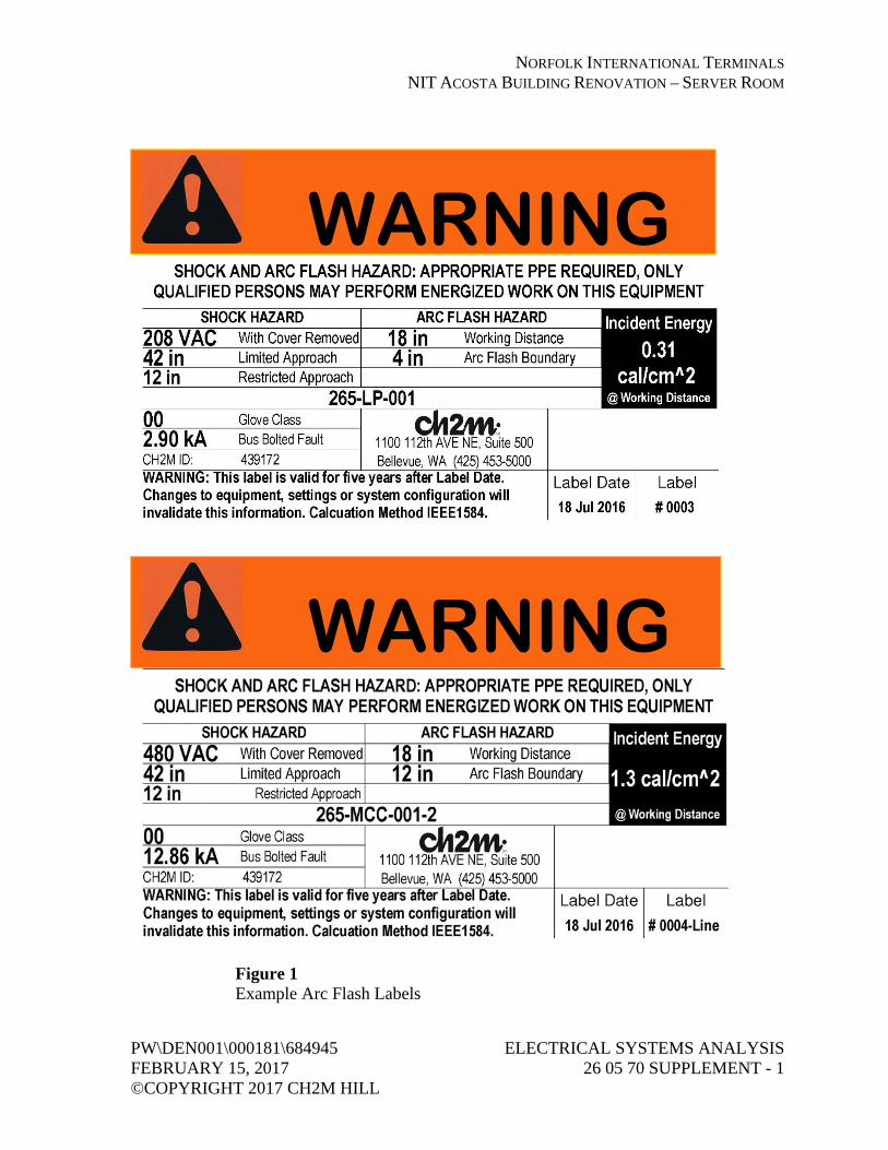
NORFOLK INTERNATIONAL TERMINALS NIT ACOSTA BUILDING RENOVATION – SERVER ROOM
PW\DEN001\000181\684945 ELECTRICAL SYSTEMS ANALYSIS FEBRUARY 15, 2017 26 05 70 SUPPLEMENT - 1 ©COPYRIGHT 2017 CH2M HILL
Figure 1 Example Arc Flash Labels
WARNING
WARNING

NORFOLK INTERNATIONAL TERMINALS NIT ACOSTA BUILDING RENOVATION – SERVER ROOM
PW\DEN001\000181\684945 COMMISSIONING OF FEBRUARY 14, 2017 ELECTRICAL SYSTEMS ©COPYRIGHT 2017 CH2M HILL 26 08 00 - 1
SECTION 26 08 00 COMMISSIONING OF ELECTRICAL SYSTEMS
PART 1 GENERAL
1.01 REFERENCES
A. The following is a list of standards which may be referenced in this section:
1. ASTM International (ASTM): a. D877, Standard Test Method for Dielectric Breakdown Voltage of
Insulating Liquids Using Disk Electrodes. b. D923, Standard Practice for Sampling Electrical Insulating
Liquids. c. D924, Standard Test Method for Dissipation Factor (or Power
Factor) and Relative Permittivity (Dielectric Constant) of Electrical Insulating Liquids.
d. D971, Standard Test Method for Interfacial Tension of Oil Against Water by the Ring Method.
e. D974, Standard Test Method for Acid and Base Number by Color-Indicator Titration.
f. D1298, Standard Test Method for Density, Relative Density (Specific Gravity), or API Gravity of Crude Petroleum and Liquid Petroleum Products by Hydrometer Method.
g. D1500, Standard Test Method for ASTM Color of Petroleum Products (ASTM Color Scale).
h. D1524, Standard Test Method for Visual Examination of Used Electrical Insulating Oils of Petroleum Origin in the Field.
i. D1533, Standard Test Method for Water in Insulating Liquids by Coulometric Karl Fischer Titration.
j. D1816, Standard Test Method for Dielectric Breakdown Voltage of Insulating Oils of Petroleum Origin Using VDE Electrodes.
2. Institute of Electrical and Electronics Engineers (IEEE): a. 43, Recommended Practice for Testing Insulating Resistance of
Rotating Machinery. b. 48, Standard Test Procedures and Requirements for Alternating-
Current Cable Terminators Used on Shielded Cables Having Laminated Insulation Rated 2.5 kV through 765 kV or Extruded Insulation Rated 2.5kV through 500kV.
c. 81, Guide for Measuring Earth Resistivity, Ground Impedance, and Earth Surface Potentials of a Ground System.
d. 95, Recommended Practice for Insulation Testing of AC Electric Machinery (2300V and Above) with High Direct Voltage.

NORFOLK INTERNATIONAL TERMINALS NIT ACOSTA BUILDING RENOVATION – SERVER ROOM
COMMISSIONING OF PW\DEN001\000181\684945 ELECTRICAL SYSTEMS FEBRUARY 14, 2017 26 08 00 - 2 ©COPYRIGHT 2017 CH2M HILL
e. 386, Standard for Separable Insulated Connector Systems for Power Distribution Systems Above 600V.
f. 400, Guide for Field Testing and Evaluation of the Insulation of Shielded Power Cable Systems.
g. 450, Recommended Practice for Maintenance, Testing, and Replacement of Vented Lead-Acid Batteries for Stationary Applications.
h. C2, National Electrical Safety Code. i. C37.20.1, Standard for Metal-Enclosed Low Voltage Power
Circuit Breaker Switchgear. j. C37.20.2, Standard for Metal-Clad Switchgear. k. C37.20.3, Standard for Metal-Enclosed Interrupter Switchgear. l. C37.23, Standard for Metal-Enclosed Bus. m. C62.33, Standard Test Specifications for Varistor Surge-
Protective Devices. 3. Insulated Cable Engineers Association (ICEA):
a. S-93-639, 5-46 kV Shielded Power Cables for Use in the Transmission and Distribution of Electric Energy.
b. S-94-649, Concentric Neutral Cables Rated 5 through 46 kV. c. S-97-682, Standard for Utility Shielded Power Cables Rated
5 through 46 kV. 4. National Electrical Manufacturers Association (NEMA):
a. AB 4, Guidelines for Inspection and Preventive Maintenance of Molded Case Circuit Breakers Used in Commercial and Industrial Applications.
b. PB 2, Deadfront Distribution Switchboards. c. WC 74, 5-46 kV Shielded Power Cable for Use in the
Transmission and Distribution of Electric Energy. 5. InterNational Electrical Testing Association (NETA): ATS, Acceptance
Testing Specifications for Electrical Power Distribution Equipment and Systems.
6. National Fire Protection Association (NFPA): a. 70, National Electrical Code (NEC). b. 70B, Recommended Practice for Electrical Equipment
Maintenance. c. 70E, Standard for Electrical Safety in the Workplace. d. 101, Life Safety Code.
7. National Institute for Certification in Engineering Technologies (NICET).
8. Occupational Safety and Health Administration (OSHA): CFR 29, Part 1910, Occupational Safety and Health Standards.

NORFOLK INTERNATIONAL TERMINALS NIT ACOSTA BUILDING RENOVATION – SERVER ROOM
PW\DEN001\000181\684945 COMMISSIONING OF FEBRUARY 14, 2017 ELECTRICAL SYSTEMS ©COPYRIGHT 2017 CH2M HILL 26 08 00 - 3
1.02 SUBMITTALS
A. Informational Submittals:
1. Submit 30 days prior to performing inspections or tests: a. Schedule for performing inspection and tests. b. List of references to be used for each test. c. Sample copy of equipment and materials inspection form(s). d. Sample copy of individual device test form. e. Sample copy of individual system test form.
2. Energization Plan: Prior to initial energization of electrical distribution equipment; include the following: a. Owner’s representative sign-off form for complete and accurate
arc flash labeling and proper protective device settings for equipment to be energized.
b. Staged sequence of initial energization of electrical equipment. c. Lock-out-tag-out plan for each stage of the progressive
energization. d. Barricading, signage, and communication plan notifying
personnel of newly energized equipment. 3. Submit test or inspection reports and certificates for each electrical item
tested within 30 days after completion of test: 4. Operation and Maintenance Data:
a. In accordance with Section 01 78 23, Operation and Maintenance Data.
b. After test or inspection reports and certificates have been reviewed by Engineer and returned, insert a copy of each in operation and maintenance manual.
5. Programmable Settings: At completion of performance demonstration test, submit final hardcopy printout and electronic files on compact disc of as-left setpoints, programs, and device configuration files for: a. Protective relays. b. Intelligent overload relays. c. Variable frequency drives. d. Power metering devices. e. Uninterruptible power supplies. f. Electrical communications modules.
1.03 QUALITY ASSURANCE
A. Testing Firm Qualifications:
1. Corporately and financially independent organization functioning as an unbiased testing authority.

NORFOLK INTERNATIONAL TERMINALS NIT ACOSTA BUILDING RENOVATION – SERVER ROOM
COMMISSIONING OF PW\DEN001\000181\684945 ELECTRICAL SYSTEMS FEBRUARY 14, 2017 26 08 00 - 4 ©COPYRIGHT 2017 CH2M HILL
2. Professionally independent of manufacturers, suppliers, and installers of electrical equipment and systems being tested.
3. Employer of engineers and technicians regularly engaged in testing and inspecting of electrical equipment, installations, and systems.
4. Supervising engineer accredited as Certified Electrical Test Technologist by NICET or NETA and having a minimum of 5 years’ testing experience on similar projects.
5. Technicians certified by NICET or NETA. 6. Assistants and apprentices assigned to Project at ratio not to exceed two
certified to one noncertified assistant or apprentice. 7. Registered professional engineer to provide comprehensive Project
report outlining services performed, results of such services, recommendations, actions taken, and opinions.
8. In compliance with OSHA CFR 29, Part 1910.7 criteria for accreditation of testing laboratories or a full member company of NETA.
B. Test equipment shall have an operating accuracy equal to or greater than requirements established by NETA ATS.
C. Test instrument calibration shall be in accordance with NETA ATS.
1.04 SEQUENCING AND SCHEDULING
A. Perform inspection and electrical tests after equipment listed herein has been installed.
B. Perform tests with apparatus de-energized whenever feasible.
C. Inspection and electrical tests on energized equipment shall be:
1. Scheduled with Owner prior to de-energization. 2. Minimized to avoid extended period of interruption to the operating
plant equipment.
D. Notify Owner at least 7 days prior to performing tests on energized electrical equipment.
PART 2 PRODUCTS (NOT USED)

NORFOLK INTERNATIONAL TERMINALS NIT ACOSTA BUILDING RENOVATION – SERVER ROOM
PW\DEN001\000181\684945 COMMISSIONING OF FEBRUARY 14, 2017 ELECTRICAL SYSTEMS ©COPYRIGHT 2017 CH2M HILL 26 08 00 - 5
PART 3 EXECUTION
3.01 GENERAL
A. Perform tests in accordance with requirements of Section 01 91 14, Equipment Testing and Facility Startup.
B. Tests and inspections shall establish:
1. Electrical equipment is operational within industry and manufacturer’s tolerances and standards.
2. Installation operates properly. 3. Equipment is suitable for energization. 4. Installation conforms to requirements of Contract Documents and
NFPA 70, NFPA 70E, NFPA 101, and IEEE C2.
C. Perform inspection and testing in accordance with NETA ATS, industry standards, and manufacturer’s recommendations.
D. Set, test, and calibrate circuit breakers, power monitoring meters, and other applicable devices in accordance with values established by short circuit, coordination, and harmonics studies as specified in Section 26 05 70, Electrical Systems Analysis.
E. Adjust mechanisms and moving parts of equipment for free mechanical movement.
F. Adjust and set electromechanical electronic relays and sensors to correspond to operating conditions, or as recommended by manufacturer.
G. Verify nameplate data for conformance to Contract Documents and approved Submittals.
H. Realign equipment not properly aligned and correct unlevelness.
I. Properly anchor electrical equipment found to be inadequately anchored.
J. Tighten accessible bolted connections, including wiring connections, with calibrated torque wrench/screw driver to manufacturer’s recommendations, or as otherwise specified in NETA ATS.
K. Clean contaminated surfaces with cleaning solvents as recommended by manufacturer.
L. Provide proper lubrication of applicable moving parts.

NORFOLK INTERNATIONAL TERMINALS NIT ACOSTA BUILDING RENOVATION – SERVER ROOM
COMMISSIONING OF PW\DEN001\000181\684945 ELECTRICAL SYSTEMS FEBRUARY 14, 2017 26 08 00 - 6 ©COPYRIGHT 2017 CH2M HILL
M. Inform Engineer of working clearances not in accordance with NFPA 70.
N. Investigate and repair or replace:
1. Electrical items that fail tests. 2. Active components not operating in accordance with manufacturer’s
instructions. 3. Damaged electrical equipment.
O. Electrical Enclosures:
1. Remove foreign material and moisture from enclosure interior. 2. Vacuum and wipe clean enclosure interior. 3. Remove corrosion found on metal surfaces. 4. Repair or replace, as determined by Engineer door and panel sections
having dented surfaces. 5. Repair or replace, as determined by Engineer poor fitting doors and
panel sections. 6. Repair or replace improperly operating latching, locking, or interlocking
devices. 7. Replace missing or damaged hardware. 8. Finish:
a. Provide matching paint and touch up scratches and mars. b. If required because of extensive damage, as determined by
Engineer, refinish entire assembly.
P. Replace fuses and circuit breakers that do not conform to size and type required by the Contract Documents or approved submittals.
3.02 CHECKOUT AND STARTUP
A. Voltage Field Test:
1. Check voltage at point of termination of power company supply system to Project when installation is essentially complete and is in operation.
2. Check voltage amplitude and balance between phases for loaded and unloaded conditions.
3. Unbalance Corrections: a. Make written request to power company to correct condition if
balance (as defined by NEMA) exceeds 1 percent, or if voltage varies throughout the day and from loaded to unloaded condition more than plus or minus 4 percent of nominal.
b. Obtain written certification from responsible power company official that voltage variations and unbalance are within their normal standards if corrections are not made.

NORFOLK INTERNATIONAL TERMINALS NIT ACOSTA BUILDING RENOVATION – SERVER ROOM
PW\DEN001\000181\684945 COMMISSIONING OF FEBRUARY 14, 2017 ELECTRICAL SYSTEMS ©COPYRIGHT 2017 CH2M HILL 26 08 00 - 7
B. Equipment Line Current Tests:
1. Check line current in each phase for each piece of equipment. 2. Make line current check after power company has made final
adjustments to supply voltage magnitude or balance. 3. If phase current for a piece of equipment is above rated nameplate
current, prepare equipment line phase current report that identifies cause of problem and corrective action taken.
3.03 PANELBOARDS
A. Visual and Mechanical Inspection: Include the following inspections and related work:
1. Inspect for defects and physical damage, labeling, and nameplate compliance with requirements of up-to-date drawings and panelboard schedules.
2. Exercise and perform operational tests of mechanical components and other operable devices in accordance with manufacturer’s instruction manual.
3. Check panelboard mounting, area clearances, and alignment and fit of components.
4. Check tightness of bolted electrical connections with calibrated torque wrench. Refer to manufacturer’s instructions for proper torque values.
5. Perform visual and mechanical inspection for overcurrent protective devices.
B. Electrical Tests: Include the following items performed in accordance with manufacturer’s instruction:
1. Insulation Resistance Tests: a. Applied megohmmeter dc voltage in accordance with
NETA ATS, Table 100.1. b. Each phase of each bus section. c. Phase-to-phase and phase-to-ground for 1 minute. d. With switches and breakers open. e. With switches and breakers closed. f. Control wiring except that connected to solid state components. g. Insulation resistance values equal to, or greater than, ohmic values
established by manufacturer. 2. Ground continuity test ground bus to system ground.

NORFOLK INTERNATIONAL TERMINALS NIT ACOSTA BUILDING RENOVATION – SERVER ROOM
COMMISSIONING OF PW\DEN001\000181\684945 ELECTRICAL SYSTEMS FEBRUARY 14, 2017 26 08 00 - 8 ©COPYRIGHT 2017 CH2M HILL
3.04 DRY TYPE TRANSFORMERS
A. Visual and Mechanical Inspection:
1. Physical and insulator damage. 2. Proper winding connections. 3. Bolt torque level in accordance with NETA ATS, Table 100.12, unless
otherwise specified by manufacturer. 4. Defective wiring. 5. Proper operation of fans, indicators, and auxiliary devices. 6. Removal of shipping brackets, fixtures, or bracing. 7. Free and properly installed resilient mounts. 8. Cleanliness and improper blockage of ventilation passages. 9. Verify tap-changer is set at correct ratio for rated output voltage under
normal operating conditions. 10. Verify proper secondary voltage phase-to-phase and phase-to-ground
after energization and prior to loading.
B. Electrical Tests:
1. Insulation Resistance Tests: a. Applied megohmmeter dc voltage in accordance with
NETA ATS, Table 100.5 for each: 1) Winding-to-winding. 2) Winding-to-ground.
b. Test Duration: 10 minutes with resistances tabulated at 30 seconds, 1 minute, and 10 minutes.
c. Results temperature corrected in accordance with NETA ATS, Table 100.14.
d. Temperature corrected insulation resistance values equal to, or greater than, ohmic values established by manufacturer.
e. Insulation resistance test results to compare within 1 percent of adjacent windings.
2. Perform tests and adjustments for fans, controls, and alarm functions as suggested by manufacturer.
3.05 LOW VOLTAGE CABLES, 600 VOLTS MAXIMUM
A. Visual and Mechanical Inspection:
1. Inspect each individual exposed power cable No. 6 and larger for: a. Physical damage. b. Proper connections in accordance with single-line diagram. c. Cable bends not in conformance with manufacturer’s minimum
allowable bending radius where applicable.

NORFOLK INTERNATIONAL TERMINALS NIT ACOSTA BUILDING RENOVATION – SERVER ROOM
PW\DEN001\000181\684945 COMMISSIONING OF FEBRUARY 14, 2017 ELECTRICAL SYSTEMS ©COPYRIGHT 2017 CH2M HILL 26 08 00 - 9
d. Color coding conformance with specification. e. Proper circuit identification.
2. Mechanical Connections for: a. Proper lug type for conductor material. b. Proper lug installation. c. Bolt torque level in accordance with NETA ATS, Table 100.12,
unless otherwise specified by manufacturer. 3. Shielded Instrumentation Cables for:
a. Proper shield grounding. b. Proper terminations. c. Proper circuit identification.
4. Control Cables for: a. Proper termination. b. Proper circuit identification.
5. Cables Terminated Through Window Type CTs: Verify neutrals and grounds are terminated for correct operation of protective devices.
B. Electrical Tests for Conductors No. 6 and Larger:
1. Insulation Resistance Tests: a. Utilize 1,000V dc megohmmeter for 600-volt insulated
conductors. b. Test each conductor with respect to ground and to adjacent
conductors for 1 minute. c. Evaluate ohmic values by comparison with conductors of same
length and type. d. Investigate values less than 50 megohms.
2. Continuity test by ohmmeter method to ensure proper cable connections.
C. Low-voltage cable tests may be performed by installer in lieu of independent testing firm.
3.06 MOLDED AND INSULATED CASE CIRCUIT BREAKERS
A. General: Inspection and testing limited to circuit breakers rated 70 amperes and larger and to motor circuit protector breakers rated 50 amperes and larger.
B. Visual and Mechanical Inspection:
1. Proper mounting. 2. Proper conductor size. 3. Feeder designation according to nameplate and one-line diagram. 4. Cracked casings.

NORFOLK INTERNATIONAL TERMINALS NIT ACOSTA BUILDING RENOVATION – SERVER ROOM
COMMISSIONING OF PW\DEN001\000181\684945 ELECTRICAL SYSTEMS FEBRUARY 14, 2017 26 08 00 - 10 ©COPYRIGHT 2017 CH2M HILL
5. Connection bolt torque level in accordance with NETA ATS, Table 100.12.
6. Operate breaker to verify smooth operation. 7. Compare frame size and trip setting with circuit breaker schedules or
one-line diagram. 8. Verify that terminals are suitable for 75 degrees C rated insulated
conductors.
C. Electrical Tests:
1. Insulation Resistance Tests: a. Utilize 1,000V dc megohmmeter for 480-volt and 600-volt circuit
breakers and 500V dc megohmmeter for 240-volt circuit breakers. b. Pole-to-pole and pole-to-ground with breaker contacts opened for
1 minute. c. Pole-to-pole and pole-to-ground with breaker contacts closed for
1 minute. d. Test values to comply with NETA ATS, Table 100.1.
2. Contact Resistance Tests: a. Contact resistance in microhms across each pole. b. Investigate deviation of 50 percent or more from adjacent poles
and similar breakers. 3. Primary Current Injection Test to Verify:
a. Long-time minimum pickup and delay. b. Short-time pickup and delay. c. Ground fault pickup and delay. d. Instantaneous pickup by run-up or pulse method. e. Trip characteristics of adjustable trip breakers shall be within
manufacturer’s published time-current characteristic tolerance band, including adjustment factors.
f. Trip times shall be within limits established by NEMA AB 4, Table 5-3. Alternatively, use NETA ATS, Table 100.7.
g. Instantaneous pickup value shall be within values established by NEMA AB 4, Table 5-4. Alternatively, use NETA ATS, Table 100.8.
3.07 METERING
A. Visual and Mechanical Inspection:
1. Verify meter connections in accordance with appropriate diagrams. 2. Verify meter multipliers. 3. Verify meter types and scales conform to Contract Documents. 4. Check calibration of meters at cardinal points. 5. Check calibration of electrical transducers.

NORFOLK INTERNATIONAL TERMINALS NIT ACOSTA BUILDING RENOVATION – SERVER ROOM
PW\DEN001\000181\684945 COMMISSIONING OF FEBRUARY 14, 2017 ELECTRICAL SYSTEMS ©COPYRIGHT 2017 CH2M HILL 26 08 00 - 11
3.08 GROUNDING SYSTEMS
A. Visual and Mechanical Inspection:
1. Equipment and circuit grounds in motor control center, panelboard assemblies for proper connection and tightness.
2. Ground bus connections in motor control center, panelboard assemblies for proper termination and tightness.
3. Effective transformer core and equipment grounding. 4. Accessible connections to grounding electrodes for proper fit and
tightness. 5. Accessible exothermic-weld grounding connections to verify that molds
were fully filled and proper bonding was obtained.
B. Electrical Tests:
1. Fall-of-Potential Test: a. In accordance with IEEE 81, Section 8.2.1.5 for measurement of
main ground system’s resistance. b. Main ground electrode system resistance to ground to be no
greater than 3 ohms. 2. Two-Point Direct Method Test:
a. In accordance with IEEE 81, Section 8.2.1.1 for measurement of ground resistance between main ground system, equipment frames, and system neutral and derived neutral points.
b. Equipment ground resistance shall not exceed main ground system resistance by 0.50 ohm.
3.09 AUTOMATIC TRANSFER SWITCHES
A. Visual and Mechanical Inspection:
1. Check doors and panels for proper interlocking. 2. Check connections for high resistance by low-resistance ohmmeter and
calibrated torque wrench applied to bolted joints. 3. Check positive mechanical and electrical interlock between normal and
alternate sources. 4. Check for proper operation:
a. Manual transfer function switch. b. Generator under load and nonload conditions. c. Auto-exerciser of generator under load and no-load conditions.
5. Verify settings and operation of control devices.

NORFOLK INTERNATIONAL TERMINALS NIT ACOSTA BUILDING RENOVATION – SERVER ROOM
COMMISSIONING OF PW\DEN001\000181\684945 ELECTRICAL SYSTEMS FEBRUARY 14, 2017 26 08 00 - 12 ©COPYRIGHT 2017 CH2M HILL
B. Electrical Tests:
1. Insulation Resistance Tests: a. Applied megohmmeter dc voltage in accordance with
NETA ATS, Table 100.1, for each phase with switch CLOSED in both source positions.
b. Phase-to-phase and phase-to-ground for 1 minute. c. Test values in accordance with manufacturer’s published data.
2. Contact Resistance Test: a. Contact resistance in microhms across each switch blade for both
source positions. b. Investigate values exceeding 500 micro-ohms. c. Investigate values deviating from adjacent pole by more than
50 percent. 3. Set and calibrate in accordance with Specifications, manufacturer’s
recommendations, and coordination study. a. Voltage and frequency sensing relays. b. Time delay relays. c. Engine start and shutdown relays.
4. Perform automatic transfer tests by: a. Simulating loss of normal power. b. Return to normal power. c. Simulating loss of alternate power. d. Simulating single-phase conditions for normal and alternate
sources. 5. Monitor and verify operation and timing of:
a. Normal and alternate voltage sensing relays. b. Engine-start sequence. c. Timing delay upon transfer and retransfer. d. Engine cool down and shutdown. e. Interlocks and limit switch functions. f. Engine cool down and shutdown feature.
3.10 EMERGENCY GENERATOR SYSTEMS
A. Visual and Mechanical Inspection:
1. Proper grounding. 2. Blockage of ventilating passageways. 3. Proper operation of jack water heaters. 4. Integrity of engine cooling and fuel supply systems. 5. Excessive mechanical and electrical noise. 6. Overheating of engine or generator. 7. Proper installation of vibration isolators.

NORFOLK INTERNATIONAL TERMINALS NIT ACOSTA BUILDING RENOVATION – SERVER ROOM
PW\DEN001\000181\684945 COMMISSIONING OF FEBRUARY 14, 2017 ELECTRICAL SYSTEMS ©COPYRIGHT 2017 CH2M HILL 26 08 00 - 13
8. Proper cooling liquid type and level. 9. Operate engine-generator and check for:
a. Excessive mechanical and electrical noise. b. Overheating. c. Correct rotation. d. Check resistance temperature detectors or generator inherent
thermal protectors for functionability and proper operation. e. Excessive vibration.
10. Verify voltage regulator and governor operation will cause unit speed and output voltage to stabilize at proper values within reasonable length of time.
11. Proper operation of meters and instruments. 12. Compare generator nameplate rating and connection with one-line
diagram or approved Submittal.
B. Electrical and Mechanical Tests:
1. Cold start test by interrupting normal power source with test load consisting of connected building load to verify: a. Transfer switch operation. b. Automatic starting operation. c. Operating ability of engine-generator. d. Overcurrent devices capability to withstand inrush currents.
2. Phase rotation tests. 3. Test engine protective shutdown features for:
a. Low oil pressure. b. Overtemperature. c. Overspeed.
4. Vibration baseline test on generator in accordance with manufacturer’s recommendations.
5. Load bank test with reactors and resistors adjusted to 80 percent power factor for each load step. Record voltage, frequency, load current, oil pressure, and engine coolant temperature at 15-minute intervals: a. 25 percent applied load for 30 minutes. b. 50 percent applied load for 30 minutes. c. 75 percent applied load for 30 minutes. d. 100 percent applied load for 3 hours. e. Load test results to demonstrate ability of unit to deliver rated load
for test period. 6. One-Step Rated kW Load Pickup Test:
a. Perform test immediately after performing load bank test. b. Apply rated load, minus largest rated hp motor, to generator.

NORFOLK INTERNATIONAL TERMINALS NIT ACOSTA BUILDING RENOVATION – SERVER ROOM
COMMISSIONING OF PW\DEN001\000181\684945 ELECTRICAL SYSTEMS FEBRUARY 14, 2017 26 08 00 - 14 ©COPYRIGHT 2017 CH2M HILL
c. Start largest rated horsepower motor and record voltage drop for 20 cycles minimum with high-speed chart recorder or digital storage oscilloscope.
d. Compare voltage drop with maximum allowable voltage dip for specified starting situation.
END OF SECTION

NORFOLK INTERNATIONAL TERMINALS NIT ACOSTA BUILDING RENOVATION – SERVER ROOM
PW\DEN001\000181\684945 LOW-VOLTAGE TRANSFORMERS FEBRUARY 15, 2017 26 22 00 - 1 ©COPYRIGHT 2017 CH2M HILL
SECTION 26 22 00 LOW-VOLTAGE TRANSFORMERS
PART 1 GENERAL
1.01 REFERENCES
A. The following is a list of standards which may be referenced in this section:
1. Institute of Electrical and Electronics Engineers (IEEE): C57.96, Guide for Loading Dry Type Transformers.
2. National Electrical Contractor’s Association (NECA): 409, Recommended Practice for Installing and Maintaining Dry-Type Transformers.
3. National Electrical Manufacturers Association (NEMA): a. 250, Enclosures for Electrical Equipment (1000 Volts Maximum). b. ST 20, Dry-Type Transformers for General Applications. c. TP 1, Guide For Determining Energy Efficiency for Distribution
Transformers. 4. National Fire Protection Association (NFPA): 70, National Electrical
Code (NEC). 5. Underwriters Laboratories Inc. (UL):
a. 486E, Standard for Equipment Wiring Terminals for use with Aluminum and/or Copper Conductors.
b. 489, Standard for Molded-Case Circuit Breakers, Molded-Case Switches, and Circuit Breaker Enclosures.
c. 1561, Standard for Dry-Type, General Purpose, and Power Transformers.
1.02 SUBMITTALS
A. Action Submittals:
1. Descriptive information. 2. Dimensions and weight. 3. Transformer nameplate data. 4. Schematic and connection diagrams.
B. Informational Submittals:
1. Test Report: Sound test certification for dry type power transformers (0- to 600-volt, primary).

NORFOLK INTERNATIONAL TERMINALS NIT ACOSTA BUILDING RENOVATION – SERVER ROOM
LOW-VOLTAGE TRANSFORMERS PW\DEN001\000181\684945 26 22 00 - 2 FEBRUARY 15, 2017 ©COPYRIGHT 2017 CH2M HILL
2. Component and attachment testing seismic certificate of compliance as required by Section 01 45 33, Special Inspection, Observation, and Testing.
PART 2 PRODUCTS
2.01 GENERAL
A. UL 1561, NEMA ST 20, unless otherwise indicated.
B. Dry-type, self-cooled, two-winding, with copper windings.
C. Units larger than 5 kVA suitable for use with 75 degrees C wire at full NFPA 70, 75 degrees C ampacity.
D. Efficiency: Meet or exceed DOE 2016 efficiency requirements.
E. Maximum Sound Level per NEMA ST 20:
1. 40 decibels for 0 to 9 kVA. 2. 45 decibels for 10 to 50 kVA. 3. 50 decibels for 51 to 150 kVA. 4. 55 decibels for 151 to 300 kVA. 5. 60 decibels for 301 to 500 kVA.
F. Overload Capability: Short-term overload in accordance with IEEE C57.96.
G. Wall Bracket: For single-phase units, 15 to 37-1/2 kVA, and for three-phase units, 15 to 30 kVA.
H. Vibration Isolators:
1. Rated for transformer’s weight. 2. Isolation Efficiency: 99 percent, at fundamental frequency of sound
emitted by transformer. 3. Less Than 30 kVA: Isolate entire unit from structure with external
vibration isolators. 4. 30 kVA and Above: Isolate core and coil assembly from transformer
enclosure with integral vibration isolator.
I. Manufacturers:
1. General Electric Co. 2. Square D Co. 3. Eaton/Cutler-Hammer.

NORFOLK INTERNATIONAL TERMINALS NIT ACOSTA BUILDING RENOVATION – SERVER ROOM
PW\DEN001\000181\684945 LOW-VOLTAGE TRANSFORMERS FEBRUARY 15, 2017 26 22 00 - 3 ©COPYRIGHT 2017 CH2M HILL
2.02 K-RATED TRANSFORMER
A. Insulation Class and Temperature Rise: Manufacturer’s standard. 115 degrees C temperature rise.
B. Core and Coil: Sized and configured to reduce overheating caused by harmonic components.
C. Enclosure: NEMA 250, Type 2.
D. Voltage Taps: Six 2.5 percent, full capacity; two above and four below normal voltage rating.
E. K Factor: K-4.
F. Neutral Bus and Terminal: 200 percent of rated current.
G. Electrostatic shield.
PART 3 EXECUTION
3.01 INSTALLATION
A. Install in accordance with NECA and manufacturer’s instructions.
B. Load external vibration isolator such that no direct transformer unit metal is in direct contact with mounting surface.
C. Provide moisture-proof, flexible conduit for electrical connections.
D. Connect voltage taps to achieve (approximately) rated output voltage under normal plant load conditions.
E. Provide wall brackets for single-phase units, 15 to 167-1/2 kVA, and three-phase units, 15 to 112 kVA.
F. Isolation Transformer: Ground isolation shields to unit enclosure with conductor of same material, and same size minimum, as shield ground lead provided with unit.
END OF SECTION

NORFOLK INTERNATIONAL TERMINALS NIT ACOSTA BUILDING RENOVATION – SERVER ROOM
PW\DEN001\000181\684945 PANELBOARDS FEBRUARY 15, 2017 26 24 16 - 1 ©COPYRIGHT 2017 CH2M HILL
SECTION 26 24 16 PANELBOARDS
PART 1 GENERAL
1.01 REFERENCES
A. The following is a list of standards which may be referenced in this section:
1. National Electrical Contractor’s Association (NECA): 407, Recommended Practice for Installing and Maintaining Panelboards.
2. National Electrical Manufacturers Association (NEMA): a. 250, Enclosures for Electrical Equipment (1000 Volts Maximum). b. 289, Application Guide for Ground Fault Circuit Interrupters. c. KS 1, Enclosed Switches. d. PB 1, Panelboards. e. PB 1.1, General Instructions for Proper Installation, Operation and
Maintenance of Panelboards Rated 600 Volts or Less. 3. National Fire Protection Association (NFPA): 70, National Electrical
Code (NEC). 4. Underwriters Laboratories, Inc. (UL):
a. 67, Standard for Panelboards. b. 98, Standard for Enclosed and Dead-Front Switches. c. 486E, Standard for Equipment Wiring Terminals for use with
Aluminum and/or Copper Conductors. d. 489, Molded-Case Circuit Breakers, Molded-Case Switches, and
Circuit Breaker Enclosures. e. 508, Standard for Industrial Control Equipment. f. 870, Wireways, Auxiliary Gutters and Associated Fittings. g. 943, Ground-Fault Circuit-Interrupters. h. 1699, Standard for Arc-Fault Circuit-Interrupters.
1.02 SUBMITTALS
A. Action Submittals:
1. Manufacturer’s data sheets for each type of panelboard, protective device, accessory item, and component.
2. Manufacturer’s shop drawings including dimensioned plan, section, and elevation for each panelboard type, enclosure, and general arrangement.
3. Tabulation of features for each panelboard to include the following: a. Protective devices with factory settings. b. Provisions for future protective devices. c. Space for future protective devices.

NORFOLK INTERNATIONAL TERMINALS NIT ACOSTA BUILDING RENOVATION – SERVER ROOM
PANELBOARDS PW\DEN001\000181\684945 26 24 16 - 2 FEBRUARY 15, 2017 ©COPYRIGHT 2017 CH2M HILL
d. Voltage, frequency, and phase ratings. e. Enclosure type. f. Bus and terminal bar configurations and current ratings. g. Provisions for circuit terminations with wire range. h. Short circuit current rating of assembled panelboard at system
voltage. i. Features, characteristics, ratings, and factory settings of auxiliary
components. j. Anchorage and bracing drawings and cut sheets, as required by
Section 01 88 15, Anchorage and Bracing.
B. Informational Submittals:
1. Anchorage and bracing calculations as required by Section 01 88 15, Anchorage and Bracing.
2. Manufacturer’s recommended installation instructions. 3. Component and attachment testing seismic certificate of compliance as
required by Section 01 45 33, Special Inspection, Observation, and Testing.
1.03 QUALITY ASSURANCE
A. Listing and Labeling: Provide products specified in this section that are listed and labeled as defined in NEC Article 100.
1.04 EXTRA MATERIALS
A. Extra Materials: Furnish, tag, and box for shipment and storage the following:
Item Quantity
Touch-up paint for panelboards One half-pint container
PART 2 PRODUCTS
2.01 MANUFACTURERS
A. Materials, equipment, and accessories specified in this section shall be products of:
1. Eaton/Cutler-Hammer. 2. General Electric Co. 3. Square D Co. 4. Siemens.

NORFOLK INTERNATIONAL TERMINALS NIT ACOSTA BUILDING RENOVATION – SERVER ROOM
PW\DEN001\000181\684945 PANELBOARDS FEBRUARY 15, 2017 26 24 16 - 3 ©COPYRIGHT 2017 CH2M HILL
2.02 GENERAL
A. Provide low voltage panelboards for application at 600V or less in accordance with this section.
B. Provide equipment in accordance with NEMA PB 1, NFPA 70, and UL 67.
C. Wire Terminations: Provide panelboard assemblies, including protective devices, suitable for use with 75 degrees C or greater wire insulation systems at NFPA 70, 75 degrees C conductor ampacity, and in accordance with UL 486E.
D. Load Current Ratings:
1. Unless otherwise indicated, load current ratings for panelboard assemblies, including bus and circuit breakers, are noncontinuous as defined by NEC. Continuous ratings shall be 80 percent of noncontinuous rating.
2. Where indicated “continuous” or “100 percent,” selected components and protective devices shall be rated for continuous load current at value shown.
E. Short Circuit Current Rating (SCCR): Integrated equipment short circuit rating for each panelboard assembly shall be no less than the following:
1. Minimum SCCR at 208Y/120 or 120/240 volts shall be 22,000 amperes rms symmetrical.
2. Minimum SCCR at 480Y/277 volts shall be 65,000 amperes rms symmetrical.
2.03 OVERCURRENT PROTECTIVE DEVICES
A. Overcurrent Device Mounting and Arrangement: Design panelboards to accommodate device installation and replacement without disturbing adjacent devices and without removing main bus.
B. Overcurrent Protective Devices: In accordance with NEMA KS 1, UL 98, and UL 489. Protective devices shall be adapted to panelboard installation.
C. Provisions for Future Overcurrent Device:
1. Provide space, mountings and bus connections such that like device may be installed without additional hardware.
2. Panel openings shall be closed with individual removable cover for each provision for future device.
NORFOLK INTERNATIONAL TERMINALS NIT ACOSTA BUILDING RENOVATION – SERVER ROOM
PANELBOARDS PW\DEN001\000181\684945 26 24 16 - 4 FEBRUARY 15, 2017 ©COPYRIGHT 2017 CH2M HILL
3. Unless otherwise indicated, “spaces” in panelboards shall be fully equipped provision for future like devices.
4. Provisions for future devices shall be suitable devices rated no less than 60 amperes.
D. Branch Protective Devices:
1. Provide Wire Lug Load Connections: Removable/replaceable, and suitable for 75 degrees C rated conductors without derating switch nor conductor ampacity.
2. Provide a nameplate for each circuit, blanks for spares.
2.04 CIRCUIT BREAKERS
A. General: Thermal-magnetic unless otherwise indicated, quick-make, quick-break, molded case, of indicating type showing ON/OFF and TRIPPED positions of operating handle.
B. Bus Connection: Bolt-on circuit breakers in all panelboards.
C. Trip Mechanism:
1. Individual permanent thermal and magnetic trip elements in each pole. 2. Variable magnetic trip elements with a single continuous adjustment
3X to 10X for frames greater than 100 amps. 3. Two and three pole, common trip. 4. Automatically opens all poles when overcurrent occurs on one pole. 5. Test button on cover. 6. Calibrated for 40 degrees C ambient, unless shown otherwise.
D. Unacceptable Substitution:
1. Do not substitute single-pole circuit breakers with handle ties for multi-pole breakers.
2. Do not use tandem or dual circuit breakers in normal single-pole spaces.
E. Specialty Breakers: Where indicated, provide breakers with the following features:
1. Ground Fault Circuit Interrupter (GFCI): Rated to trip on 5-mA ground fault within 0.025 second (UL 943, Class A sensitivity, for protection of personnel). Ground fault sensor shall be rated same as circuit breaker. Breaker shall include push-to-test and reset buttons.

NORFOLK INTERNATIONAL TERMINALS NIT ACOSTA BUILDING RENOVATION – SERVER ROOM
PW\DEN001\000181\684945 PANELBOARDS FEBRUARY 15, 2017 26 24 16 - 5 ©COPYRIGHT 2017 CH2M HILL
F. Solid State Trip Units: Where indicated, equip breakers with solid state trip units as listed below.
1. Long (Time) Short (Time) Instantaneous (LSI): Electronic trip unit with fixed long-time trip, adjustable short-time trip and delay, and adjustable instantaneous trip settings.
2.05 ENCLOSURES
A. General:
1. Provide as specified in Section 26 05 04, Basic Electrical Materials and Methods.
2. Type 1, Type 3R, and Type 3S material code-gauge, hot-dip galvanized sheet steel with reinforced steel frame.
3. Provide surface-mount panelboard from trim with same dimensions as box front.
B. Finish: Rust inhibitor prime followed by manufacturer’s standard gray baked enamel or lacquer.
C. NEMA 250 Type 1 Branch Panelboard Enclosure:
1. Secure front trim to box with concealed trim clamps. 2. Overlap flush panelboards front trims with box nominal 3/4 inch on all sides. 3. Provide door in panelboard front trim, with concealed hinges, to access
protective device operating handles. 4. Provide multi-point latching for doors over 30 inches in height. 5. Door Lock: Secure with flush catch and tumbler lock; all panelboards keyed
alike, with two milled keys each lock. 6. Circuit Directory: Metal frame with transparent plastic face and enclosed
card, mounted inside each panel door.
D. Multi-Section Panelboards: Where more than one section is required, provide multiple panelboard sections with separate fronts.
1. Sections shall be suitable for individual mounting to be field interconnected to form a single electrical unit.
2. Recessed-mount sections of the same panel shall all have the same size tubs and flush covers.
3. Surface-mount multi-section panelboards may be comprised of sections of unequal heights.
4. Provide feed-through and main lugs in individual sections as required for field assembly of a complete multi-section panelboard. Unless otherwise indicated, provide feed-through lugs on each section but last.
5. Provide neutral and ground terminal bars in each section.

NORFOLK INTERNATIONAL TERMINALS NIT ACOSTA BUILDING RENOVATION – SERVER ROOM
PANELBOARDS PW\DEN001\000181\684945 26 24 16 - 6 FEBRUARY 15, 2017 ©COPYRIGHT 2017 CH2M HILL
2.06 BUSSING AND TERMINAL BARS
A. Bus:
1. Material: Tin-plated copper full sized throughout length. 2. Provide for mounting of future protective devices along full length of
bus regardless of number of units and spaces shown. Machine, drill, and tap as required for current and future positions.
B. Equipment Ground Terminal Bus: Copper with suitably sized provisions for termination of ground conductors, and bonded to box.
1. Provide individual mechanical termination points no less than the quantity of breaker pole positions.
2. Provide individual termination points for all other grounding conductors such as feeder, grounding electrode, etc.
3. Termination points shall be bolted crimp compression lugs for conductors 6 AWG and larger.
C. Neutral Terminal Bus: Copper with suitably sized provisions for termination of neutral conductors, and isolated from box.
1. Provide individual mechanical termination points no less than the quantity of breaker pole positions.
2. Provide individual termination points for all other neutral conductors. 3. Termination Points: Bolted crimp compression lugs for conductors
6 AWG and larger.
D. Provision for Future Devices: Equip with mounting brackets, bus connections, and necessary appurtenances for future protective device ampere ratings indicated.
2.07 SPECIAL FEATURES
A. General: Where indicated on Drawings or schedules, provide special features as specified.
B. Surge Arresters:
1. Comply with Section 26 43 00, Transient Voltage Suppression. 2. Provide protective device within panelboard as disconnecting means
and short circuit protection per manufacturer’s recommendation.

NORFOLK INTERNATIONAL TERMINALS NIT ACOSTA BUILDING RENOVATION – SERVER ROOM
PW\DEN001\000181\684945 PANELBOARDS FEBRUARY 15, 2017 26 24 16 - 7 ©COPYRIGHT 2017 CH2M HILL
C. Shunt Trip Mechanism: Provide shunt trip mechanism for the main circuit breaker where shown or indicated. Shunt trip control circuit shall be 120V ac rated.
PART 3 EXECUTION
3.01 GENERAL
A. Install in accordance with NECA 407, NEMA PB 1.1, and manufacturers’ written installation instructions.
B. Install securely, plumb, in-line and square with walls.
C. Install top of cabinet trim 78 inches above floor, unless otherwise shown. Install cabinet so tops of protective device operating handles are no more than 78 inches above the floor.
D. Ground Fault Protection: Install panelboard ground fault circuit interrupter devices in accordance with installation guidelines of NEMA 289.
E. Install filler plates in unused spaces.
F. Wiring in Panel Gutters: Train conductors neatly in groups; bundle and wrap with nylon wire ties.
G. Mount flush panels uniformly flush with wall finish.
H. Provide typewritten circuit directory for each panelboard.
I. Provide engraved identification for each protective device.
END OF SECTION


NORFOLK INTERNATIONAL TERMINALS NIT ACOSTA BUILDING RENOVATION – SERVER ROOM
PW\DEN001\000181\684945 WIRING DEVICES FEBRUARY 15, 2017 26 27 26 - 1 ©COPYRIGHT 2017 CH2M HILL
SECTION 26 27 26 WIRING DEVICES
PART 1 GENERAL
1.01 REFERENCES
A. The following is a list of standards which may be referenced in this section:
1. ASTM International (ASTM): A167, Standard Specification for Stainless and Heat-Resisting Chromium-Nickel Steel Plate, Sheet, and Strip.
2. Federal Specifications (FS): a. W-C-596G, General Specification for Connector, Electrical,
Power. b. W-S-896F, Switches, Toggle (Toggle and Lock), Flush Mounted
(General Specification). 3. Institute of Electrical and Electronic Engineers, Inc. (IEEE):
a. C62.41.2, Recommended Practice on Characterization of Surges in Low-Voltage (1000V and less) AC Power Circuits.
b. C62.45, Recommended Practice on Surge Testing for Equipment Connected to Low-Voltage (1000V and less) AC Power Circuits.
4. National Electrical Contractors Association (NECA): 1, Standard Practice of Good Workmanship in Electrical Contracting.
5. National Electrical Manufacturers Association (NEMA): a. 250, Enclosures for Electrical Equipment (1000 Volts Maximum). b. FB 11, Plugs, Receptacles, and Connectors of the Pin and Sleeve
Type for Hazardous Locations. c. WD 1, General Color Requirements for Wiring Devices. d. WD 6, Wiring Devices – Dimensional Specifications.
6. National Fire Protection Association (NFPA): 70, National Electrical Code (NEC).
7. Underwriters Laboratories Inc. (UL): a. 498, Standard for Safety for Attachment Plugs and Receptacles. b. 508, Standard for Safety for Industrial Control Equipment. c. 943, Standard for Safety for Ground-Fault Circuit-Interrupters. d. 1010, Standard for Safety for Receptacle-Plug Combinations for
Use in Hazardous (Classified) Locations. e. 1436, Standard for Safety for Outlet Circuit Testers and Similar
Indicating Devices. f. 1449, Standard for Safety for Surge Protective Devices (SPD).

NORFOLK INTERNATIONAL TERMINALS NIT ACOSTA BUILDING RENOVATION – SERVER ROOM
WIRING DEVICES PW\DEN001\000181\684945 26 27 26 - 2 FEBRUARY 15, 2017 ©COPYRIGHT 2017 CH2M HILL
1.02 SUBMITTALS
A. Action Submittals: Manufacturer’s product data for wiring devices.
PART 2 PRODUCTS
2.01 SWITCHES
A. Switch, General Purpose:
1. NEMA WD 1 and FS W-S-896F. 2. Totally enclosed, ac type, with quiet tumbler switch and screw terminal. 3. Rivetless one-piece brass or copper alloy contact arm with silver alloy
contact. 4. Capable of controlling 100 percent tungsten filament and fluorescent
lamp loads. 5. Rating: 20 amps, 120/277 volts. 6. Automatic grounding clip and integral grounding terminal on mounting
strap. 7. Manufacturers and Products, Industrial Grade:
a. Bryant; 4901 Series. b. Hubbell; 1221 Series. c. Leviton; 1221 Series.
2.02 RECEPTACLES
A. Receptacle, General Purpose:
1. NEMA WD 1 and FS W-C-596G. 2. Duplex, two-pole, three-wire grounding type with screw type wire
terminals. 3. Impact resistant nylon cover and body, with finder grooves in face,
unless otherwise indicated. 4. One-piece mounting strap with integral ground contact (rivetless
construction). 5. Contact Arrangement: Contact to be made on two sides of each inserted
blade without detent. 6. Rating: 125 volts, NEMA WD 1, Configuration 5-20R, 20 amps, unless
otherwise indicated. 7. Size: For 2-inch by 4-inch outlet box. 8. Industrial Grade Manufacturers and Products:
a. Cooper Arrow Hart; 5362 Series. b. Hubbell Bryant; HBL5362 Series. c. Leviton; 5362 Series.

NORFOLK INTERNATIONAL TERMINALS NIT ACOSTA BUILDING RENOVATION – SERVER ROOM
PW\DEN001\000181\684945 WIRING DEVICES FEBRUARY 15, 2017 26 27 26 - 3 ©COPYRIGHT 2017 CH2M HILL
B. Receptacle, Ground Fault Circuit Interrupter:
1. Meet requirements of general-purpose receptacle. 2. Listed Class A to UL 943, tripping at 5 mA. 3. Rectangular smooth face with push-to-test and reset buttons. 4. Listed weather-resistant per NEC 406.8. 5. Feed-through Capability: 20 amps. 6. Manufacturers and Products:
a. Hubbell Bryant; GFTR20 Series. b. Cooper Arrow Hart; WRVGF20 Series. c. Leviton; 7599 or 7899 Series.
2.03 DEVICE PLATES
A. Sectional type plate not permitted.
B. Nylon:
1. Material: Specification grade, 0.10-inch minimum thickness, noncombustible, thermosetting.
2. Color: To match associated wiring device. 3. Mounting Screw: Oval-head metal, color matched to plate.
C. Metal:
1. Material: Specification grade, one-piece, 0.040-inch nominal thickness stainless steel.
2. Finish: ASTM A167, Type 302/304, satin. 3. Mounting Screw: Oval-head, finish matched to plate.
D. Cast Metal:
1. Material: Malleable ferrous metal or copper-free aluminum, with gaskets.
2. Screw: Oval-head stainless steel.
E. Sheet Steel:
1. Finish: Zinc electroplate. 2. Screws: Oval-head stainless steel. 3. Manufacturers:
a. Appleton. b. Crouse-Hinds.

NORFOLK INTERNATIONAL TERMINALS NIT ACOSTA BUILDING RENOVATION – SERVER ROOM
WIRING DEVICES PW\DEN001\000181\684945 26 27 26 - 4 FEBRUARY 15, 2017 ©COPYRIGHT 2017 CH2M HILL
F. Engraved:
1. Character Height: 1/8-inch. 2. Filler: Black.
G. Raised Sheet Metal: 1/2-inch high zinc- or cadmium-plated steel designed for one-piece drawn type sheet steel box.
H. Sheet Steel: Formed sheet steel or Feraloy designed for installation on cast-metal box.
PART 3 EXECUTION
3.01 INSTALLATION, GENERAL
A. Comply with NECA 1.
B. Coordination with Other Trades:
1. Ensure device and its box are protected. Do not place wall finish materials over device box and do not cut holes for box with router that is guided by riding against outside of box.
2. Keep outlet box free of plaster, drywall joint compound, mortar, cement, concrete, dust, paint, and other material that may contaminate raceway system, conductors, and cables.
3. Install device box in brick or block wall such that cover plate does not cross a joint, unless otherwise indicated. Where indicated or directed to cross joint, trowel joint flush with face of wall.
4. Install wiring device after wall preparation, including painting, is complete.
C. Conductors:
1. Do not strip insulation from conductors until just before they are spliced or terminated on devices.
2. Strip insulation evenly around conductor using tools designed for the purpose. Avoid scoring or nicking of solid wire or cutting strands from stranded wire.
3. Length of free conductors at outlets for devices shall meet provisions of NFPA 70, Article 300, without pigtails.
4. Existing Conductors: a. Cut back and pigtail, or replace damaged conductors. b. Straighten conductors that remain and remove corrosion and
foreign matter.

NORFOLK INTERNATIONAL TERMINALS NIT ACOSTA BUILDING RENOVATION – SERVER ROOM
PW\DEN001\000181\684945 WIRING DEVICES FEBRUARY 15, 2017 26 27 26 - 5 ©COPYRIGHT 2017 CH2M HILL
c. Pigtailing existing conductors is permitted provided outlet box is large enough.
D. Device Installation:
1. Replace devices that have been in temporary use during construction or that show signs they were installed before building finishing operations were complete.
2. Keep each wiring device in its package or otherwise protected until it is time to connect conductors.
3. Do not remove surface protection, such as plastic film and smudge covers, until last possible moment.
4. Connect devices to branch circuits using pigtails that are not less than 6 inches in length.
5. Use torque screwdriver when a torque is recommended or required by manufacturer.
6. When conductors larger than 12 AWG are installed on 15- or 20-amp circuits, splice 12 AWG pigtails for device connections.
7. Tighten unused terminal screws on device. 8. Device Plates:
a. Do not use oversized or extra deep plate. b. Repair wall finishes and remount outlet box when standard device
plate does not fit flush or does not cover rough wall opening.
3.02 SWITCH INSTALLATION
A. Switch, General Purpose:
1. Mounting Height: See Section 26 05 33, Raceway and Boxes. 2. Install with switch operation in vertical position. 3. Install single-pole, two-way switch such that toggle is in up position
when switch is on.
3.03 RECEPTACLE INSTALLATION
A. Duplex Receptacle:
1. Install with grounding slot up, except where horizontal mounting is shown, in which case install with neutral slot up.
2. Ground receptacle to box with grounding wire only. 3. Ground Fault Interrupter: Install feed-through model at locations where
ground fault protection is specified for “downstream” conventional receptacles.

NORFOLK INTERNATIONAL TERMINALS NIT ACOSTA BUILDING RENOVATION – SERVER ROOM
WIRING DEVICES PW\DEN001\000181\684945 26 27 26 - 6 FEBRUARY 15, 2017 ©COPYRIGHT 2017 CH2M HILL
3.04 DEVICE PLATE INSTALLATION
A. Securely fasten to wiring device; ensure tight fit to box.
B. Flush Mounted: Install with all four edges in continuous contact with finished wall surface without use of mat or similar material. Plaster fillings will not be acceptable.
C. Surface Mounted: Plate shall not extend beyond sides of box, unless plate has no sharp corners or edges.
D. Install with alignment tolerance to box of 1/16 inch.
E. Engrave with designated title.
F. Type (Unless Otherwise Shown):
1. Office Areas: Metal. 2. Exterior:
a. Switch: Weatherproof. b. Receptacle in Damp Location: Weatherproof Type 1. c. Receptacle in Wet Location: Weatherproof Type 2.
G. Interior:
1. Flush Mounted Box: Metal. 2. Surface Mounted, Metal Box:
a. General Purpose Areas: Sheet steel. b. Other Areas: Cast.
3. Surface Mounted, Aluminum Box: a. General Purpose Areas: Stamped. b. Other Areas: Cast.
4. Surface Mounted, Sheet Steel Box: Raised sheet steel. 5. Surface Mounted, Nonmetallic Box: Manufacturer’s standard.
3.05 IDENTIFICATION
A. Use tape labels for identification of individual wall switches and receptacles in dry indoor locations.
1. Degrease and clean device plate surface to receive tape labels. 2. Use 3/16-inch Kroy black letters on white background, unless otherwise
indicated. 3. Identify panelboard and circuit number from which item is served on
face of plate.

NORFOLK INTERNATIONAL TERMINALS NIT ACOSTA BUILDING RENOVATION – SERVER ROOM
PW\DEN001\000181\684945 WIRING DEVICES FEBRUARY 15, 2017 26 27 26 - 7 ©COPYRIGHT 2017 CH2M HILL
B. Identify conductors with durable wire markers or tags inside outlet boxes where more than one circuit is present.
3.06 FIELD QUALITY CONTROL
A. Perform tests and inspections, and prepare test reports.
B. Test Instrument for 125-Volt 20-Amp Receptacle: Digital wiring analyzer with digital readout or illuminated LED indicators of measurement.
C. Using test plug, verify device and its outlet box are securely mounted.
D. Line Voltage Range: 105 to 132 volts.
E. Percent Voltage Drop under 15-Amp Load: Less than 6 percent; 6 percent or higher is not acceptable.
F. Ground Impedance: 2 ohms, maximum.
G. GFCI Trip: Test for tripping values specified in UL 1436 and UL 943.
H. Tests shall be diagnostic, indicating damaged conductors, high resistance at circuit breaker, poor connections, inadequate fault current path, defective devices, or similar problems. Correct circuit conditions, remove malfunctioning units and replace with new ones, and retest as specified above.
END OF SECTION

NORFOLK INTERNATIONAL TERMINALS NIT ACOSTA BUILDING RENOVATION – SERVER ROOM
PW\DEN001\000181\684945 AUTOMATIC TRANSFER SWITCHES FEBRUARY 15, 2017 26 36 23 - 1 ©COPYRIGHT 2017 CH2M HILL
SECTION 26 36 23 AUTOMATIC TRANSFER SWITCHES
PART 1 GENERAL
1.01 REFERENCES
A. The following is a list of standards which may be referenced in this section:
1. Institute of Electrical and Electronics Engineers (IEEE): C37.90.1, Standard for Surge Withstand Capability (SWC) Tests for Relays and Relay Systems Associated with Electric Power Apparatus.
2. National Electrical Manufacturers Association (NEMA): a. ICS 1, General Standards for Industrial Control and Systems:
General Requirements. b. ICS 2, Industrial Control and Systems Controllers, Contactors,
and Overload Relays not more than 2000 volts ac or 750 volts ac. c. ICS 6, Industrial Control And Systems: Enclosures 250,
Enclosures for Electrical Equipment (1,000 Volts Maximum). 3. National Fire Protection Association (NFPA): 70, National Electrical
Code (NEC). 4. Underwriters Laboratories, Inc. (UL): 1008, Transfer Switch Equipment.
1.02 SUBMITTALS
A. Action Submittals:
1. Descriptive product information. 2. Dimensional drawings. 3. Control diagrams. 4. Conduit entrance locations. 5. Equipment ratings.
B. Informational Submittals:
1. Manufacturer’s Certificate of Compliance, in accordance with Section 01 43 33, Manufacturers’ Field Services.
2. Factory certified test reports. 3. Component and attachment testing seismic certificate of compliance as
required by Section 01 45 33, Special Inspection, Observation, and Testing.
4. Operation and Maintenance Data: As specified in Section 01 78 23, Operation and Maintenance Data.

NORFOLK INTERNATIONAL TERMINALS NIT ACOSTA BUILDING RENOVATION – SERVER ROOM
AUTOMATIC TRANSFER SWITCHES PW\DEN001\000181\684945 26 36 23 - 2 FEBRUARY 15, 2017 ©COPYRIGHT 2017 CH2M HILL
1.03 QUALITY ASSURANCE
A. Authority Having Jurisdiction (AHJ):
1. Provide the Work in accordance with NFPA 70, National Electrical Code (NEC). Where required by the AHJ, material and equipment shall be labeled or listed by a nationally recognized testing laboratory or other organization acceptable to the AHJ in order to provide a basis for approval under NEC.
2. Materials and equipment manufactured within the scope of standards published by UL shall conform to those standards and shall have an applied UL listing mark.
PART 2 PRODUCTS
2.01 MANUFACTURERS
A. ASCO.
B. GE Zenith.
2.02 GENERAL
A. Transfer switch to be product of a single manufacturer in order to achieve standardization for appearance, operation, maintenance, spare parts, and manufacturer’s service.
B. In accordance with applicable standards of NFPA 70, NEMA ICS 1, NEMA ICS 2, NEMA ICS 6, IEEE C37.90.1, and UL 1008.
C. Transfer switch consisting of inherently double-throw power switch unit with interconnected control module.
D. Rated 100 percent, in amperes, for total system transfer of motor, electric heating, discharge lamp loads, and tungsten-filament lamp loads.
1. Switches rated 400 amperes and below suitable for 100 percent tungsten-filament lamp loads.
2. Switches rated above 400 amperes suitable for 30 percent tungsten-filament lamp loads.

NORFOLK INTERNATIONAL TERMINALS NIT ACOSTA BUILDING RENOVATION – SERVER ROOM
PW\DEN001\000181\684945 AUTOMATIC TRANSFER SWITCHES FEBRUARY 15, 2017 26 36 23 - 3 ©COPYRIGHT 2017 CH2M HILL
E. Main and arcing contacts visible for inspection with cabinet door and barrier covers removed.
F. Suitable for 480 volts, three-phase, three-wire, grounded-wye electrical service having an available short circuit current at line terminals of 65,000 amperes rms symmetrical.
G. Switch Rating: 600 continuous amperes in nonventilated enclosure.
H. Current carrying capacity of arcing contacts shall not be used to determine the transfer switch rating.
I. Suitable for use with 75 degrees C wire at full NFPA 70, 75 degrees C ampacity.
J. Operating Conditions:
1. Ambient Temperature: Maximum 40 degrees C. 2. Equipment to be fully rated without any derating for operating
conditions listed above.
K. Install the current transformer (CT) and CT shorting (or test block) supplied by load bank manufacturer on the load side of transfer switch inside the transfer switch enclosure as shown on Drawings.
2.03 ENCLOSURE
A. Type: Nonventilated NEMA 250, Type 12 with enclosure grounding terminal.
B. Dead front, front accessible floor mounted cabinet with 14-gauge welded steel construction.
C. Continuously hinged single door, with handle and lock cylinder.
D. Finish: Baked enamel applied over rust-inhibiting, phosphated base coating.
1. Exterior and Interior Color: Provide gray finish as approved by Engineer.
2. Unpainted Metal Parts: Plated for corrosion resistance.
2.04 TRANSFER SWITCH
A. Type: Electrically operated, mechanically held, double-throw.
B. Momentarily energized, single-electrically operated mechanism energized from source to which load is to be transferred.

NORFOLK INTERNATIONAL TERMINALS NIT ACOSTA BUILDING RENOVATION – SERVER ROOM
AUTOMATIC TRANSFER SWITCHES PW\DEN001\000181\684945 26 36 23 - 4 FEBRUARY 15, 2017 ©COPYRIGHT 2017 CH2M HILL
C. Locking mechanism to maintain constant contact pressure.
D. Mechanical interlock switch to ensure only one of two possible switch positions.
E. Silver alloy contacts protected by arcing contacts.
F. Main and arcing contacts visible when door is open and barrier covers removed.
G. Manual operating handle for transfer in either direction under either loaded or unloaded conditions.
H. Internal control wire connections made with ring or spade type terminals, lock washers, and sleeve type marking labels.
2.05 CONTROL MODULE
A. Completely enclosed and mounted separately from the transfer switch unit.
B. Microprocessor for sensing and logic control with inherent digital communications capability.
C. Plug-in, industrial grade interfacing relays with dust covers.
D. Connected to transfer switch by wiring harness having keyed disconnect plug.
E. Plug-in printed circuit boards for sensing and control logic.
F. Adjustable solid state undervoltage sensors for all three phases of normal and for one phase of standby source:
1. Pickup 85 to 100 percent nominal. 2. Dropout 75 to 98 percent of pickup setting.
G. Adjustable frequency sensors for standby emergency source:
1. Pickup 90 to 100 percent nominal. 2. Dropout 87 to 89 percent of pickup setting.
H. Control module with adjustable time delays:
1. 0.5- to 6-second engine start delay. 2. 0- to 5-minute load transfer to emergency delay. 3. 0- to 30-minute retransfer to normal delay. 4. 0- to 30-minute unload running time delay. 5. Switch to bypass any of the above time delays during testing.

NORFOLK INTERNATIONAL TERMINALS NIT ACOSTA BUILDING RENOVATION – SERVER ROOM
PW\DEN001\000181\684945 AUTOMATIC TRANSFER SWITCHES FEBRUARY 15, 2017 26 36 23 - 5 ©COPYRIGHT 2017 CH2M HILL
I. Form-C start contacts, rated 10 amperes, 32V dc, for two-wire engine control, wired to terminal block.
2.06 METERING INSTRUMENTS
A. Meters to be connected to load side of transfer switch.
B. Ammeter: LED digital type with current transformers, three-phase, line-to-line, OFF, four-position selector switch.
C. Voltmeter: LED digital type with three-phase, line-to-line, OFF, four-position selector switch and 600-volt scale.
2.07 INDICATORS
A. Type: Manufacturer’s standard.
B. Green lens to indicate switch position for normal power source.
C. Red lens to indicate switch position for standby power source.
D. White lens to indicate normal power source is available within parameters established by pickup and dropout settings.
E. Amber lens to indicate standby power source is available within parameters established by pickup and dropout settings.
F. Provide one normally open and one normally closed, 5 amperes, 120-volt contact for remote indication when transfer switch is in either position.
2.08 FACTORY TESTS
A. Test to Ensure Correct:
1. Operation of individual components. 2. Sequence of operation. 3. Transfer time, voltage, frequency, and time delay settings.
B. Dielectric strength test in accordance with NEMA ICS 1.

NORFOLK INTERNATIONAL TERMINALS NIT ACOSTA BUILDING RENOVATION – SERVER ROOM
AUTOMATIC TRANSFER SWITCHES PW\DEN001\000181\684945 26 36 23 - 6 FEBRUARY 15, 2017 ©COPYRIGHT 2017 CH2M HILL
PART 3 EXECUTION
3.01 INSTALLATION
A. Install in accordance with manufacturer’s instructions.
END OF SECTION
NORFOLK INTERNATIONAL TERMINALS NIT ACOSTA BUILDING RENOVATION – SERVER ROOM
PW\DEN001\000181\684945 TRANSIENT VOLTAGE SUPPRESSION FEBRUARY 15, 2017 26 43 00 - 1 ©COPYRIGHT 2017 CH2M HILL
SECTION 26 43 00 TRANSIENT VOLTAGE SUPPRESSION
PART 1 GENERAL
1.01 SUBMITTALS
A. Submit product data on each suppressor type, indicating component values, part numbers, and conductor sizes. Include dimensional drawing for each, showing mounting arrangements.
B. Submit manufacturer’s Underwriters Laboratories, Inc. (UL) certified test data and nameplate data for each TVSS.
C. Submit electrical single-line diagram showing location of each TVSS.
1.02 QUALITY ASSURANCE
A. UL Compliance and Labeling:
1. For power and signal circuits, TVSS devices shall comply with UL 1449 and complimentary listed to UL 1283 as an electromagnetic interference filter. Provide units that are listed and labeled by UL.
2. For telephone circuit protection, TVSS devices shall comply with UL 497A.
B. ANSI Compliance: Use TVSS devices in compliance with the recommendations of IEEE C62.41.1, IEEE C62.41.2, and IEEE C62.45.
PART 2 PRODUCTS
2.01 GENERAL
A. All TVSS devices for power circuits, provided under this section, shall be the product of a single manufacturer.
B. TVSS devices shall be capable of performance at ambient temperatures between minus 40 and 60 degrees C, at relative humidity ranging from 0 to 95 percent, and at altitudes ranging from sea level to 12,000 feet.
C. TVSS devices shall be fused to disconnect the suppressor from the electrical source should the suppressor fail. The fusing shall allow full surge handling capabilities and to afford safety protection from thermal overloads and short circuits.

NORFOLK INTERNATIONAL TERMINALS NIT ACOSTA BUILDING RENOVATION – SERVER ROOM
TRANSIENT VOLTAGE SUPPRESSION PW\DEN001\000181\684945 26 43 00 - 2 FEBRUARY 15, 2017 ©COPYRIGHT 2017 CH2M HILL
D. Design TVSS devices for the specific type and voltage of the electrical service. Single-phase and three-phase wye-configured systems shall have L-N, L-G, and N-G protection. Grounded delta-configured systems shall have L-L and L-G protection.
E. Power Filter: The TVSS shall include a high frequency extended range power filter complimentary listed to UL 1283 as an electromagnetic interference filter.
2.02 MANUFACTURER
A. Innovative Technology, VanGuard Series.
B. Advanced Protection Technologies, Inc.
C. General Electric.
2.03 MAIN DISTRIBUTION TVSS
A. Provide TVSS meeting IEEE C62.41.1 and IEEE C62.41.2 Location in accordance with Category C.
B. Surge current capacity shall be not less than the following:
1. L-N Capacity: 200 kA. 2. L-G Capacity: 120 kA. 3. N-G Capacity: 120 kA.
C. Suppressor housing shall be in an enclosure that has the same NEMA rating as the equipment it protects and painted to match.
D. UL 1449 maximum suppression voltage shall not be more than:
System Voltage Phase L-L or L-N
Suppression Voltage
120 1 400
208Y/120 3 400
240 3 800
480Y/277 3 800

NORFOLK INTERNATIONAL TERMINALS NIT ACOSTA BUILDING RENOVATION – SERVER ROOM
PW\DEN001\000181\684945 TRANSIENT VOLTAGE SUPPRESSION FEBRUARY 15, 2017 26 43 00 - 3 ©COPYRIGHT 2017 CH2M HILL
2.04 PANELBOARD TVSS
A. Provide TVSS meeting IEEE C62.41.1 and IEEE C62.41.2 Location Category B.
B. Surge current capacity shall be not less than the following:
1. L-L Capacity: 80 kA. 2. L-N Capacity: 80 kA. 3. L-G Capacity: 80 kA. 4. N-G Capacity: 80 kA.
C. Suppressor shall be in an enclosure that has the same NEMA rating as the panel it protects or the TVSS may be integral to a panelboard.
D. UL 1449 maximum clamp voltage shall not be more than:
System Voltage Phase L-L or L-N Clamp
Voltage
120 1 400
208Y/120 3 400
240 3 800
480Y/277 3 800
2.05 ANNUNCIATION
A. Provide unit or separately mounted LED-type indication lights to show the normal and failed status of each module. Provide one normally open and one normally closed contacts which operate when the unit fails.
2.06 SURGE COUNTER
A. Provide each TVSS rated above 100 kA with a counter displaying the number of voltage transients that have occurred on the unit input. The counter shall be battery backed and retain the count through system power outages.
2.07 PAIRED CABLE DATA LINE INTERIOR SUPPRESSORS
A. Provide units meeting IEEE C62.41, Location Category A.
B. Use bi-polar 1,500-watt silicon avalanche diodes between the protected conductor and earth ground.

NORFOLK INTERNATIONAL TERMINALS NIT ACOSTA BUILDING RENOVATION – SERVER ROOM
TRANSIENT VOLTAGE SUPPRESSION PW\DEN001\000181\684945 26 43 00 - 4 FEBRUARY 15, 2017 ©COPYRIGHT 2017 CH2M HILL
C. Provide units with a maximum single impulse current rating of 80 amperes (10 by 1,000 microsecond-waveform).
D. Breakdown voltage shall not exceed 36 volts.
2.08 PAIRED CABLE DATA LINE EXTERIOR SUPPRESSORS
A. Provide units meeting IEEE C62.41, Location Category A.
B. Suppressors shall be a hybrid design with a minimum of three stages, utilizing solid-state components and operating bi-directionally.
C. Suppressors shall meet or exceed the following criteria:
1. Maximum single impulse current rating of 10,000 amperes (8- by 20-microsecond-waveform).
2. Pulse Life Rating: 3,000 amperes (8- by 20-microsecond-waveform): 2,000 occurrences.
3. Maximum clamping voltage at 10,000 amperes (8- by 20-microsecond current waveform), shall not exceed the peak of the normal applied signal voltage by 200 percent.
PART 3 EXECUTION
3.01 APPLICATION REQUIREMENTS
A. Install TVSS when indicated on the Drawings and:
1. Main Distribution TVSS in or near each low-voltage switchgear (load center).
2. Main distribution TVSS in or near each motor control center. 3. Panelboard TVSS In or near each distribution panelboard unless
otherwise indicated.
B. Electronic Equipment Paired Cable Conductors: Install data line suppressors at the low voltage input and output of each piece of equipment, including telephone cable entrance.
1. Use secondary protectors on lines that do not exit the structure. 2. Use primary protectors on lines that exit and enter the structure.
3.02 GENERAL INSTALLATION REQUIREMENTS
A. Install suppressors according to manufacturer’s recommendations.

NORFOLK INTERNATIONAL TERMINALS NIT ACOSTA BUILDING RENOVATION – SERVER ROOM
PW\DEN001\000181\684945 TRANSIENT VOLTAGE SUPPRESSION FEBRUARY 15, 2017 26 43 00 - 5 ©COPYRIGHT 2017 CH2M HILL
B. Install suppressors directly to the cabinet which houses the circuit to be protected so that the suppressor leads are straight and short, with all conductors laced, running directly to the point of connection within the panel, without loops or bends. If bends are unavoidable, no bend may exceed 90 degrees and bending radius may not be less than 6 inches.
C. Connecting wires shall be as short as possible with gently twisted conductors, tied together, to prevent separation. Connecting wires shall not exceed 24 inches in length at any point.
D. Field installed conductors shall be the same as specified for building wire, not smaller than No. 8 AWG and not larger than No. 4 AWG. Device leads shall not be longer than the length recommended by the manufacturer, unless specifically reviewed and approved by the manufacturer.
E. Provide dedicated disconnecting means for TVSS devices installed at main service entrance location, switchgear, and motor control centers. Provide dedicated 30- to 60-ampere circuit breakers (size dependent upon wire size used) with number of poles as required, as disconnecting means for TVSS devices installed at panelboards. The interrupting capacity of the circuit breakers shall be that specified for the other breakers at that location.
END OF SECTION


NORFOLK INTERNATIONAL TERMINALS NIT ACOSTA BUILDING RENOVATION – SERVER ROOM
PW\DEN001\000181\684945 LIGHTING FEBRUARY 15, 2017 26 50 00 - 1 ©COPYRIGHT 2017 CH2M HILL
SECTION 26 50 00 LIGHTING
PART 1 GENERAL
1.01 REFERENCES
A. The following is a list of standards which may be referenced in this section:
1. ASTM International (ASTM): a. A123/A123M, Standard Specification for Zinc (Hot-Dip Galvanized) Coatings
on Iron and Steel Products. b. A153/A153M, Standard Specification for Zinc Coating (Hot-Dip) on Iron and
Steel Hardware. c. A572/A572A, Standard Specification for High-Strength Low-Alloy Columbium-
Vanadium Structural Steel. d. A588/A588M, Standard Specification for High-Strength Low-Alloy Structural
Steel, with 50 ksi [345 MPa] Minimum Yield Point to 4-in. [100-mm] Thick. e. A595/A595M, Standard Specification for Steel Tubes, Low-Carbon or High-
Strength Low-Alloy, Tapered for Structural Use. f. A615/A615M, Standard Specification for Deformed and Plain Carbon-Steel Bars
for Concrete Reinforcement. g. A1011/A1011M, Standard Specification for Steel, Sheet and Strip, Hot-Rolled,
Carbon, Structural, High-Strength Low-Alloy, High-Strength Low-Alloy with Improved Formability, and Ultra-High Strength.
h. D6576, Standard Specification for Flexible Cellular Rubber Chemically Blown. i. G154, Standard Practice for Operating Fluorescent Light Apparatus for UV
Exposure of Nonmetallic Materials. 2. American Wood Protection Association (AWPA): M6, Brands Used on Forest
Products. 3. Canadian Standards Association (CSA). 4. Certified Ballast Manufacturer (CBM). 5. Federal Communications Commission (FCC). 6. Illuminating Engineering Society of North America (IESNA).
a. HB-9, Lighting Handbook. b. LM-79, IES Electrical and Photometric Measurements of Solid-State Lighting
Products. c. LM-80, IESNA Approved Method for Measuring Lumen Maintenance of LED
Light Sources. d. RP (Recommended Practices) Series. e. TM-21, Projecting Long Term Lumen Maintenance of LED Light Sources.
7. Institute of Electrical and Electronics Engineers (IEEE): C62.41, Recommended Practice on Surge Voltages in Low-Voltage AC Power Circuits.

NORFOLK INTERNATIONAL TERMINALS NIT ACOSTA BUILDING RENOVATION – SERVER ROOM
LIGHTING PW\DEN001\000181\684945 26 50 00 - 2 FEBRUARY 15, 2017 ©COPYRIGHT 2017 CH2M HILL
8. National Electrical Manufacturers Association (NEMA): a. 250, Enclosures for Electrical Equipment (1,000 Volts Maximum). b. ICS 6, Industrial Control and Systems: Enclosures.
9. National Energy Policy Act. 10. National Fire Protection Association (NFPA): 70, National Electrical Code (NEC) –
Softbound Version. 11. Rural Utilities Service (RUS): 1728F-700, Specification for Wood Poles, Stubs and
Anchor Logs. 12. Underwriters Laboratories, Inc. (UL):
a. 773, UL Standard for Safety Plug-In Locking Type Photocontrols for Use with Area Lighting - Fourth Edition; Reprint with Revisions Through and Including March 08, 2002.
b. 844, Electric Lighting Fixtures for Use in Hazardous (Classified) Locations. c. 924, Emergency Lighting and Power Equipment. d. 1598, UL Standard for Safety Luminaires. e. 2108, UL Standard for Safety Low Voltage Lighting Systems - First Edition;
Reprint with Revisions through and Including February 24, 2014. f. 8750, UL Standard for Safety Light Emitting Diode (LED) Equipment for Use in
Lighting Products - First Edition; Reprint with Revisions Through and Including April 1, 2015.
13. U.S. Environmental Protection Agency and U.S. Department of Energy: Energy Star.
1.02 SUBMITTALS
A. Action Submittals:
1. Shop Drawings: a. General:
1) Provide catalog data sheets and pictures for all products listed below. 2) Proposed Luminaire Substitutions (Interior and Exterior): Provide an
electronic photometric file in standard ‘.ies’ file format in accordance with the Illumination Engineering Society of North America (IESNA) for any proposed luminaire substitution not identified on the project Luminaire Schedule. Obtain file from the luminaire manufacturer or approved independent photometric testing laboratory. Include the proposed substitute luminaire with all options identified on the project Luminaire Schedule.
b. Interior Luminaires: 1) Catalog data sheets with pictures. 2) Luminaire material, finish, dimensions, and metal gauge. 3) Lens material, pattern, and thickness. 4) Candle power distribution curves in two or more planes. 5) Candle power chart 0 degree to 90 degrees. 6) Lumen output chart.

NORFOLK INTERNATIONAL TERMINALS NIT ACOSTA BUILDING RENOVATION – SERVER ROOM
PW\DEN001\000181\684945 LIGHTING FEBRUARY 15, 2017 26 50 00 - 3 ©COPYRIGHT 2017 CH2M HILL
7) Average maximum brightness data in foot lamberts. 8) Coefficients of utilization for zonal cavity calculations. 9) Mounting or suspension details.
c. Lamps: 1) Voltages. 2) Watts. 3) Correlated color temperature (CCT). 4) Color rendering index (CRI). 5) Published rated life (in hours). Provide number of hours per start and
operating temperature for published rated life hours indicated. 6) Published rated initial and mean lumens. 7) Lumen maintenance curve. 8) Lamp type (ANSI designation, dimensions, shape, and base).
d. Ballasts: 1) Type. 2) Wiring diagram. 3) Ballast factor. 4) Nominal watts and input watts. 5) Input voltage and power factor. 6) Starting current, line current, and restrike current values. 7) Sound rating. 8) Temperature rating. 9) Efficiency ratings. 10) Low temperature characteristics. 11) Emergency Ballasts:
a) Electrical ratings. b) Lamp type compatibility. c) Battery capacity.
12) Dimming Ballasts: Operating principle (0V to 10V, etc.), dimming range, manufacturer certification for operation with proposed dimmers.
e. LED Source Systems: 1) General:
a) IESNA LM-80 test reports. b) IESNA TM-21 ratings. c) Operating temperature range. Data sheet (chart/graph) describing life
as a function of temperature. d) Warranty: Light engine and driver. e) Rated life. f) Surge protection. g) Thermal control device, heat sink. h) Enclosure and wiring information. i) Operating voltage range.
NORFOLK INTERNATIONAL TERMINALS NIT ACOSTA BUILDING RENOVATION – SERVER ROOM
LIGHTING PW\DEN001\000181\684945 26 50 00 - 4 FEBRUARY 15, 2017 ©COPYRIGHT 2017 CH2M HILL
2) Electronic Module/Light Engine: a) CCT. b) CRI.
3) Drivers: a) Input current total harmonic distortion. b) Power factor. c) Sound rating.
B. Informational Submittals:
1. Anchorage and bracing calculations as required by Section 01 88 15, Anchorage and Bracing.
2. Manufacturer’s printed installation instructions. 3. Operation and maintenance data as specified in Section 01 78 23, Operation and
Maintenance Data.
1.03 QUALITY ASSURANCE
A. Authority Having Jurisdiction (AHJ):
1. Provide Work in accordance with NFPA 70, National Electrical Code (NEC). Where required by the AHJ, provide material and equipment labeled or listed by a nationally recognized testing laboratory or other organization acceptable to the AHJ to provide a basis for approval under NEC.
2. Provide materials and equipment manufactured within the scope of standards published by Underwriters Laboratories, Inc. in conformance with those standards and with an applied UL listing mark.
B. Standard Products:
1. Provide materials and equipment of manufacturers regularly engaged in production of products specified in this section and that are of equal material, design, and workmanship.
2. Provide products that have been in satisfactory commercial or industrial use for 2 years prior to Bid opening in similar applications under similar circumstances and of similar size. Provide products that have been on sale on the commercial market through advertisements, manufacturers’ catalogs, or brochures during the 2-year period.
3. Material and Equipment Manufacturing Date: Do not use products manufactured more than 3 years prior to date of delivery to Site.
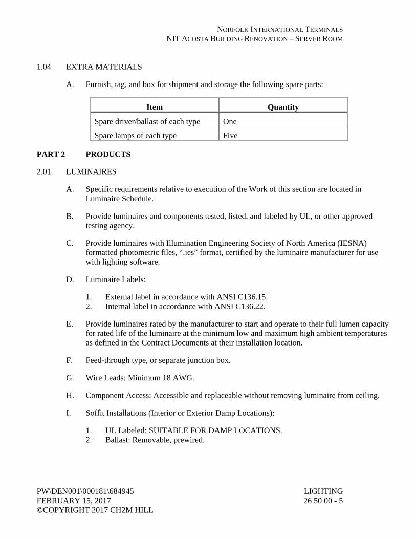
NORFOLK INTERNATIONAL TERMINALS NIT ACOSTA BUILDING RENOVATION – SERVER ROOM
PW\DEN001\000181\684945 LIGHTING FEBRUARY 15, 2017 26 50 00 - 5 ©COPYRIGHT 2017 CH2M HILL
1.04 EXTRA MATERIALS
A. Furnish, tag, and box for shipment and storage the following spare parts:
Item Quantity
Spare driver/ballast of each type One
Spare lamps of each type Five
PART 2 PRODUCTS
2.01 LUMINAIRES
A. Specific requirements relative to execution of the Work of this section are located in Luminaire Schedule.
B. Provide luminaires and components tested, listed, and labeled by UL, or other approved testing agency.
C. Provide luminaires with Illumination Engineering Society of North America (IESNA) formatted photometric files, “.ies” format, certified by the luminaire manufacturer for use with lighting software.
D. Luminaire Labels:
1. External label in accordance with ANSI C136.15. 2. Internal label in accordance with ANSI C136.22.
E. Provide luminaires rated by the manufacturer to start and operate to their full lumen capacity for rated life of the luminaire at the minimum low and maximum high ambient temperatures as defined in the Contract Documents at their installation location.
F. Feed-through type, or separate junction box.
G. Wire Leads: Minimum 18 AWG.
H. Component Access: Accessible and replaceable without removing luminaire from ceiling.
I. Soffit Installations (Interior or Exterior Damp Locations):
1. UL Labeled: SUITABLE FOR DAMP LOCATIONS. 2. Ballast: Removable, prewired.

NORFOLK INTERNATIONAL TERMINALS NIT ACOSTA BUILDING RENOVATION – SERVER ROOM
LIGHTING PW\DEN001\000181\684945 26 50 00 - 6 FEBRUARY 15, 2017 ©COPYRIGHT 2017 CH2M HILL
J. Illuminated Exit Signs:
1. Body: As scheduled. 2. Face:
a. Letters: 1) 6-inch high by 3/4-inch stroke. 2) Color: Red.
3. Mounting: As indicated. 4. Directional Arrows: As indicated on Drawings.
2.02 LAMPS
A. General:
1. Refer to Luminaire Schedule for specific lamp descriptions. 2. Lamps shall pass the Federal TCLP test in force at the time of manufacture.
2.03 LED SOURCE SYSTEMS
A. General:
1. Provide IESNA LM-80 test reports. 2. Provide Energy Star compliance for solid state luminaires. 3. Listed To: UL 8750 Standard for Safety for Light Emitting Diode (LED) Equipment
for use in Lighting Products. 4. Provide RoHS compliant LED light source(s) and driver(s). 5. Rated operating temperature range as indicated on the Luminaire Schedule. 6. Warranty: 5 years minimum.
B. Electronic Module/Light Engine:
1. Mount all components to a single plate and factory prewired with quick-disconnect plugs.
2. Include a driver, thermal control device, thermal protector device, and surge protector device. a. Provide surge protector tested in accordance with IEEE/ANSI C62.41.2 to
Category C Low. 3. Provide LEDs mounted to a metal-core circuit board and aluminum heat sink for
optimal thermal management and long life. 4. Light Engine Rating per TM-21: 100,000 at 25 degrees C, L70. 5. CCT: As indicated on the Luminaire Schedule. 6. CRI: Minimum of 70.

NORFOLK INTERNATIONAL TERMINALS NIT ACOSTA BUILDING RENOVATION – SERVER ROOM
PW\DEN001\000181\684945 LIGHTING FEBRUARY 15, 2017 26 50 00 - 7 ©COPYRIGHT 2017 CH2M HILL
C. Drivers:
1. Expected life of 100,000 hours at 25 degrees C. 2. Provide drivers mounted in an all metal can. 3. Operating Voltage Range: 50/60-Hz input source, voltage range as indicated on the
Luminaire Schedule with sustained variations of plus or minus 10 percent voltage with no damage to the driver.
4. Input Current Total Harmonic Distortion: Less than 20 percent up to 50 percent of full load rating.
5. Power Factor: Greater than 0.90 for primary application up to 50 percent of full load rating.
6. Sound rating: Class A. 7. Comply with NEMA 410 for inrush current limits.
2.04 LIGHTING CONTROL
A. Occupancy Sensors:
1. General: a. Capable of operating normally with any electronic ballast and PL lamp systems. b. Coverage of sensors shall remain constant after sensitivity control has been set.
No automatic reduction shall occur in coverage due to cycling of air conditioner or heating fans.
c. Provide sensors with readily accessible, user adjustable controls for time delay and sensitivity.
d. Provide a bypass manual OVERRIDE ON key on each sensor to allow operation in the event of sensor failure. When bypass is used, lighting shall remain on constantly or control shall divert to a wall switch until sensor is replaced. Recess bypass control to prevent tampering.
2. Sensor Technology: a. Dual Technology:
1) Sensors use a combination of passive infrared and ultrasonic technologies to detect occupants in coverage area.
2) Provide technology mode selection to allow installer to configure the operation mode between dual technology, passive infrared only, or ultrasonic only functionality.
3) Detection Range (IR Range) on Axis: 2,000 square feet. 4) No audio dual technology units will be accepted.
3. Sensor Mounting: a. Ceiling:
1) Directional Coverage: 360 degrees. b. Wall:
1) Directional Coverage: 180 degrees.

NORFOLK INTERNATIONAL TERMINALS NIT ACOSTA BUILDING RENOVATION – SERVER ROOM
LIGHTING PW\DEN001\000181\684945 26 50 00 - 8 FEBRUARY 15, 2017 ©COPYRIGHT 2017 CH2M HILL
c. Corner: 1) Coverage: 90 degrees.
d. Switch Box: 1) Directional Coverage: 180 degrees. 2) Coverage Area: At desk top level up to 300 square feet and gross motion
up to 1,000 square feet. 3) Switch Types:
a) Single circuit switches shall control a single switched circuit. b) Bi-level switches shall accommodate up to two switched circuits.
4) Loads: a) Wall box switches shall include an integral power supply. b) Switches shall accommodate loads from 0 watt to 800 watts at
120 volts; 0 watt to 1,200 watts at 277 volts. 4. Circuit Control Hardware—CU Power Packs:
a. Control Units: Able to mount through a 1/2-inch knockout in a standard electrical enclosure and be an integrated, self-contained unit consisting internally of an isolated load switching control relay and a transformer to provide low-voltage power. Transformer shall provide power to a minimum of two sensors.
b. Relay Contact Ratings: 1) 13A, 120V ac tungsten. 2) 20A, 120V ac ballast.
5. Wiring: Control wiring between sensors and control units shall be Class II, 14 AWG, stranded, UL Classified, PVC insulated or Teflon jacketed cable approved for use in plenums, where applicable.
6. Manufacturers: a. Unenco, Inc. b. The Watt Stopper, Inc.
2.05 BRACKETS AND SUPPORTS
A. Features:
1. Not less than 1-1/4-inch aluminum secured to pole. 2. Slip-fitter or pipe-threaded brackets may be used, but coordinate brackets to luminaires
provided. Provide identical brackets for use with one type of luminaire unless otherwise approved by Engineer.
3. Select brackets for pole-mounted street lights to correctly position luminaire no lower than mounting height indicated.
4. Mount brackets not less than 24 feet above street. 5. Provide special mountings or brackets as indicated on Drawings fabricated of metal
which will not promote galvanic reaction with luminaire head.
NORFOLK INTERNATIONAL TERMINALS NIT ACOSTA BUILDING RENOVATION – SERVER ROOM
PW\DEN001\000181\684945 LIGHTING FEBRUARY 15, 2017 26 50 00 - 9 ©COPYRIGHT 2017 CH2M HILL
PART 3 EXECUTION
3.01 LUMINAIRES
A. General:
1. Install in accordance with manufacturer’s recommendations. 2. Provide proper hangers, pendants, and canopies as necessary for complete installation. 3. Provide additional ceiling bracing, hanger supports, and other structural reinforcements
to building required to safely mount. 4. Install plumb and level. 5. Install each luminaire outlet box with galvanized stud.
B. Mounting:
1. General: Coordinate mounting, fastening, and environmental conditions with Section 26 05 02, Basic Electrical Requirements.
2. Wall Mounted: Measure mounting heights from center of mounting plate to finished floor or finished grade, whichever is applicable.
3. Pendant Mounted: a. Provide swivel type hangers and canopies to match luminaires, unless otherwise
noted. b. Space single-stem hangers on continuous-row fluorescent luminaires nominally
48 inches apart. c. Provide twin-stem hangers on single luminaires. d. Measure mounting heights from bottom of luminaire to finished floor or finished
grade, whichever is applicable.
C. Finished Areas:
1. Install symmetrically with tile pattern. 2. Locate with centerlines either on centerline of tile or on joint between adjacent tile
runs. 3. Install recessed luminaires tight to finished surface such that no spill light will show
between ceilings and sealing rings. 4. Combustible Low Density Cellulose Fiberboard: Provide spacers and mount luminaires
1-1/2 inches from ceiling surface, or use fixtures suitable for mounting on low density ceilings.
5. Junction Boxes: a. Flush and Recessed Luminaires: Locate minimum 1-foot from luminaire. b. In concealed locations, install junction boxes to be accessible by removing
luminaire. 6. Wiring and Conduit:
a. Provide wiring of temperature rating required by luminaire. b. Provide flexible steel conduit.

NORFOLK INTERNATIONAL TERMINALS NIT ACOSTA BUILDING RENOVATION – SERVER ROOM
LIGHTING PW\DEN001\000181\684945 26 50 00 - 10 FEBRUARY 15, 2017 ©COPYRIGHT 2017 CH2M HILL
7. Provide plaster frames when required by ceiling construction. 8. Independent Supports:
a. Provide each recessed fluorescent luminaire with two safety chains or two No. 12 soft-annealed galvanized steel wires of length needed to secure luminaire to building structure independent of ceiling structure.
b. Select chain or wire with tensile strength and method of fastening to structure adequate to support luminaire weight.
c. Fasten chain or wire to each end of luminaire.
D. Unfinished Areas: Locate luminaires to avoid conflict with other building systems or blockage of luminaire light output.
1. Fixture Suspension: Provide threaded steel hanger rods. Scissor type hangers not permitted.
2. Attachment to Steel Beams: Provide flanged beam clips and straight or angled hangers.
3.02 LAMPS
A. Provide in each fixture, number and type for which fixture is designed, unless otherwise noted.
3.03 LIGHTING CONTROL
A. Occupancy Sensors: Locate and aim sensors in correct location required for complete and proper volumetric coverage within range of coverage(s) of controlled areas per manufacturer’s recommendations. Provide 90 percent to 100 percent room coverage to accommodate all occupancy habits of single or multiple occupants at any location within room(s). Locations and quantities of sensors shown on Drawings are diagrammatic and only indicate which rooms are to be provided with sensors. Provide additional sensors if required to properly and completely cover respective room.
3.04 FIELD FINISHES
A. Paint electrical equipment as required to match finish of adjacent surfaces or to meet the indicated or specified safety criteria. Paint using standard finishes and coatings.
3.05 FIELD QUALITY CONTROL
A. Upon completion of installation, verify equipment is properly installed, connected, and adjusted. Conduct an operating test to show equipment operates in accordance with the requirements of this section.
B. Coordinate lighting and controls installation and testing with commissioning as specified in Section 01 91 14, Equipment Testing and Facility Startup.

NORFOLK INTERNATIONAL TERMINALS NIT ACOSTA BUILDING RENOVATION – SERVER ROOM
PW\DEN001\000181\684945 LIGHTING FEBRUARY 15, 2017 26 50 00 - 11 ©COPYRIGHT 2017 CH2M HILL
3.06 MANUFACTURER’S SERVICES
A. Occupancy Sensors: Furnish manufacturer’s representative at Job Site in accordance with Section 01 43 33, Manufacturers’ Field Services, to inspect installation, test unit, and put into service.
3.07 CLEANING
A. Remove labels and markings, except UL listing mark.
B. Wipe luminaires inside and out to remove construction dust.
C. Clean luminaire plastic lenses with antistatic cleaners only.
D. Touch up painted surfaces of luminaires and poles with matching paint ordered from manufacturer.
E. Replace defective lamps at time of Substantial Completion.
END OF SECTION


NORFOLK INTERNATIONAL TERMINALS NIT ACOSTA BUILDING RENOVATION – SERVER ROOM
PW\DEN001\000181\684945 HORIZONTAL AIR FLOW FEBRUARY 15, 2017 OUTDOOR RESISTIVE LOAD BANK ©COPYRIGHT 2017 CH2M HILL (50 TO 150 KW) 26 60 00 - 1
SECTION 26 60 00 HORIZONTAL AIR FLOW OUTDOOR RESISTIVE LOAD BANK
(50 TO 150 KW)
PART 1 GENERAL
1.01 SCOPE
A. This specification contains the minimum requirements for the design, manufacture and testing of a UL-listed, air-cooled, outdoor weatherproof resistive load bank.
B. The load bank is required for periodic exercising and testing of the (standby) emergency power source. The load bank shall be permanently mounted in a weatherproof enclosure, forced-air cooled with remotely mounted control panel.
C. Related Sections: Section 26 36 23, Automatic Transfer Switches.
1.02 SUBMITTALS
A. The manufacturer shall submit for review technical data including features, performance, electrical characteristics, physical characteristics, ratings, accessories, and finishes
B. Action Submittals:
1. Shop Drawings: Shall include dimensional plans, front and side elevations and mounting details sufficient to properly install the load bank. Load bus configuration and load connections termination area shall be clearly identified.
C. Informational Submittals: Electrical schematic drawings shall be provided to detail the operation of the load bank and the provided safety circuits. Over-current protection and control devices shall be identified and their ratings marked. A system interconnection drawing shall be included for control wiring related to the load bank.
1.03 STANDARDS
A. The equipment covered by this specification shall be designed with the latest applicable NEMA, NEC, and ANSI standards.
B. The load bank shall be listed to UL Standard 508A.

NORFOLK INTERNATIONAL TERMINALS NIT ACOSTA BUILDING RENOVATION – SERVER ROOM
HORIZONTAL AIR FLOW PW\DEN001\000181\684945 OUTDOOR RESISTIVE LOAD BANK FEBRUARY 15, 2017 (50 TO 150 KW) ©COPYRIGHT 2017 CH2M HILL 26 60 00 - 2
1.04 QUALITY CONTROL
A. The load bank shall be fully tested using a test specification written by the supplier. Tests shall include electrical functional testing, verifying conformance to assembly drawings and specifications. Each load step shall be cold resistance checked to verify proper calibration of resistive load steps and proper ohmic value.
B. The manufacturer shall maintain this data on file for inspection purposes by the purchaser. Tests using high potential equipment shall be performed to ensure isolation of the load circuits from the control circuits and to determine isolation of the load circuits from the load bank frame. Tests of all safety circuits shall be performed to verify conformance to the specification.
C. All electrical circuits shall have a high potential insulation resistance test performed at twice rated voltage plus 1,000V ac to assure insulation integrity.
D. All quality control test equipment shall be regularly maintained and calibrated to traceable national standards.
E. The company’s quality system shall be ISO 9001 certified.
1.05 QUALIFICATIONS OF MANUFACTURER
A. The load bank shall be manufactured by a firm regularly engaged in the manufacture of load banks and who can demonstrate at least 20 years experience with at least 20 installations of load banks similar or equal to the ones specified herein.
B. The manufacturer shall have a written quality control procedure available for review by the purchaser, which will document all phases of operations, engineering, and manufacturing.
C. Manufacturer must have a field service organization with service personnel having a minimum of an associate degree in electrical engineering.
D. The load bank shall be Avtron Loadbank, as manufactured by Emerson Network Power, or preapproved equal.

NORFOLK INTERNATIONAL TERMINALS NIT ACOSTA BUILDING RENOVATION – SERVER ROOM
PW\DEN001\000181\684945 HORIZONTAL AIR FLOW FEBRUARY 15, 2017 OUTDOOR RESISTIVE LOAD BANK ©COPYRIGHT 2017 CH2M HILL (50 TO 150 KW) 26 60 00 - 3
PART 2 PRODUCTS
2.01 RATINGS
A. The total capacity of the load bank shall be rated 150 KW at 480 volts, 3-phase, 3-wire, 60-Hz, 300 amps per phase at unity power factor and 5 KW minimum load step resolution.
B. The load bank shall be designed for continuous duty cycle operation with no limitations. The load bank shall operate in an ambient temperature of minus 28 to 49 degrees C (minus 20 to 120 degrees F).
2.02 MATERIAL AND CONSTRUCTION
A. The load bank shall be outdoor weatherproof construction, suitable for installation on a concrete pad or structural base. All exterior fasteners shall be stainless steel. The load bank shall include forklift channels in the base for lifting.
B. The load bank shall be constructed of heavy gauge aluminized steel in accordance with ASTM A463.
C. The main input load bus, load step relays, fuses and blower/control relays shall be located within the load bank enclosure. A thermostatically controlled heater shall be located within the control section to provide protection to the control devices from the effects of moisture and condensation.
D. Airflow throughout the load bank shall be horizontal. Intake openings shall be designed to prevent objects greater than 0.50-inch diameter from entering the unit.
E. The load bank exhaust hood shall be angled downward. The exhaust hood shall be constructed of non-corrosive aluminized steel or aluminum.
F. The load bank enclosure shall have a baked polyester powder-coated finish with a film thickness of 2.8 plus or minus 0.4 mils per coat.
G. Load elements shall be contained in an integral resistor case. Resistors can be individually removed for inspection or service.
2.03 RESISTIVE LOAD ELEMENTS
A. Load elements shall be Avtron Helidyne™, helically wound chromium alloy rated to operate at approximately one-half of maximum continuous rating of

NORFOLK INTERNATIONAL TERMINALS NIT ACOSTA BUILDING RENOVATION – SERVER ROOM
HORIZONTAL AIR FLOW PW\DEN001\000181\684945 OUTDOOR RESISTIVE LOAD BANK FEBRUARY 15, 2017 (50 TO 150 KW) ©COPYRIGHT 2017 CH2M HILL 26 60 00 - 4
wire. Elements must be fully supported across the entire length within the air stream by segmented ceramic insulators on stainless steel rods. Element supports shall be designed to prevent a short circuit to adjacent elements or to ground.
B. The change in resistance due to temperature shall be minimized by maintaining conservative watt densities.
C. The overall tolerance of the load bank shall be minus 0 to 5 percent KW at rated voltage. A minus 5 percent, plus 5 percent rating allows the load bank to deliver less than rated KW and shall not be used. The load bank must deliver full rated KW at rated voltage.
2.04 COOLING
A. The load bank shall be cooled by integral TEFC or TEAO motor(s), direct-coupled to the cooling fan blade. The fan motor must be electrically protected against overload using a motor overload device and short circuit protected using 3 current limiting fuses with an interrupting rating of 200 K A.I.C.
B. The fan blade is to be an airfoil design constructed from aluminum or non-corroding material.
C. An integral control power transformer shall be provided to supply 120V, 1-phase, 60-Hz to the load banks control and motor starter circuitry. Transformer primary and secondary control circuits shall be fuse protected.
2.05 PROTECTIVE DEVICES
A. A differential pressure switch shall be provided to detect air loss. The switch shall be electrically interlocked with the load application controls to prevent load from being applied if cooling air is not present.
B. An over-temperature switch shall be provided to sense the load bank exhaust in the heater case assembly. The switch shall be electrically interlocked with the load application controls to remove load from being applied in the event of an over temperature condition.
C. To provide for major fault protection, branch fuses shall be provided on all three phases of switched load steps above 50 KW. Branch fuses shall be current limiting type with an interrupting rating of 200 K A.I.C.
D. The exterior of the load bank shall have appropriate warning/caution statements on access panels.

NORFOLK INTERNATIONAL TERMINALS NIT ACOSTA BUILDING RENOVATION – SERVER ROOM
PW\DEN001\000181\684945 HORIZONTAL AIR FLOW FEBRUARY 15, 2017 OUTDOOR RESISTIVE LOAD BANK ©COPYRIGHT 2017 CH2M HILL (50 TO 150 KW) 26 60 00 - 5
2.06 CONTROL PANEL
A. The control panel shall be a remote 19-inch rack mounted panel housed in a NEMA 4 type wall mount enclosure.
1. The control panel shall contain the following manual controls: a. Power ON/OFF switch. b. Blower START/STOP pushbuttons. c. Master load ON/OFF switch. d. Load step switches for ON/OFF application of individual load
steps. 2. Control panel visual indicators shall be as follows:
a. Power ON indication light. b. Blower ON light. c. Blower/Air FAILURE light. d. OVERTEMPERATURE light.
B. A standard remote load dump circuit shall be provided as part of the load bank control circuit. Provisions shall be provided to remove the load bank off-line from the operation of a remote normally closed set of auxiliary contacts from a transfer switch or other device. In the event of the remote contact opening, all load is removed.
C. An automatic load step controller shall be provided for maintaining a minimum load on the generator set. The controller shall monitor the connected downstream loads and will automatically add or subtract load steps in response to building load changes as to maintain a minimum load level on the generator set. The controller includes an initial time-delay circuit, and automatic time delayed load step application circuit. A remote contact closure is required for activation and transfer of control. A separate current transformer (CT) and a CT shorting switch (or test block) shall be supplied loose for mounting and sensing of downstream loads. CT and associated CT shorting switch (or test block) shall be mounted in an automatic transfer switch enclosure as shown by others.
2.07 DOCUMENTATION
A. Installation and operation manuals shall be provided with the equipment and shall include complete details for the installation, commissioning, operation, and maintenance of the load bank.
B. The manuals shall include the electrical schematic and interconnect drawings for the power and control wiring for the load bank and all control devices.

NORFOLK INTERNATIONAL TERMINALS NIT ACOSTA BUILDING RENOVATION – SERVER ROOM
HORIZONTAL AIR FLOW PW\DEN001\000181\684945 OUTDOOR RESISTIVE LOAD BANK FEBRUARY 15, 2017 (50 TO 150 KW) ©COPYRIGHT 2017 CH2M HILL 26 60 00 - 6
C. A complete parts list with part numbers, device identification, and rating shall be included in the manuals. The original manufacturers name and part number shall be included in the parts listing.
D. Two sets of manuals shall be provided with the load bank.
PART 3 EXECUTION
3.01 INSTALLATION
A. Level and securely mount load bank set in accordance with manufacturer’s recommendations.
3.02 FIELD FINISHING
A. Touch up damaged coating with paint system compatible to existing.
3.03 FIELD TESTS
A. Performance Test: Perform upon completion of installation, including the following.
1. Operate 2 hours minimum. 2. Manufacturer’s representative shall make necessary adjustments. 3. Demonstrate ability of load bank set to provide and automatically shed
specified loads. 4. Demonstrate proper operation of equipment, including automatic
operation with control from automatic transfer switch, to Engineer and Owner.
5. Refer to Section 26 08 00, Commissioning of Electrical Systems for testing requirements.
6. Test Report: Record and include in the report the following: a. Electric load on load bank. b. Load bank load and load shedding. c. Load bank temperature. d. Verification of automatic operation with control from automatic
transfer switch. 7. Post-test Requirements: Make final adjustments.

NORFOLK INTERNATIONAL TERMINALS NIT ACOSTA BUILDING RENOVATION – SERVER ROOM
PW\DEN001\000181\684945 HORIZONTAL AIR FLOW FEBRUARY 15, 2017 OUTDOOR RESISTIVE LOAD BANK ©COPYRIGHT 2017 CH2M HILL (50 TO 150 KW) 26 60 00 - 7
3.04 MANUFACTURER’S SERVICES
A. Manufacturer’s Representative: Present at Site or classroom designated by Owner, for minimum person-days listed below, travel time excluded.
1. 1 person-day for installation assistance and inspection. 2. 0.5 person-day for functional and performance testing and completion
of Manufacturer’s Certificate of Proper Installation. 3. 0.5 person-day for prestartup classroom or Site training. 4. 0.5 person-day for facility startup. 5. 0.5 person-day for post-startup training of Owner’s personnel.
B. See Section 01 43 33, Manufacturers’ Field Services and Section 01 91 14, Equipment Testing and Facility Startup.
C. Level and securely mount load bank set in accordance with manufacturer’s recommendations.
3.05 FIELD FINISHING
A. Touch up damaged coating with paint system compatible to existing.
3.06 FIELD TESTS
A. Performance Test: Perform upon completion of installation, including the following.
1. Operate 2 hours minimum. 2. Manufacturer’s representative shall make necessary adjustments. 3. Demonstrate ability of load bank set to provide and automatically shed
specified loads. 4. Demonstrate proper operation of equipment, including automatic
operation with control from automatic transfer switch, to Engineer and Owner.
5. Refer to Section 26 08 00, Commissioning of Electrical Systems for testing requirements.
6. Test Report: Record and include in the report the following: a. Electric load on load bank. b. Load bank load and load shedding. c. Load bank temperature. d. Verification of automatic operation with control from automatic
transfer switch. 7. Post-test Requirements: Make final adjustments.

NORFOLK INTERNATIONAL TERMINALS NIT ACOSTA BUILDING RENOVATION – SERVER ROOM
HORIZONTAL AIR FLOW PW\DEN001\000181\684945 OUTDOOR RESISTIVE LOAD BANK FEBRUARY 15, 2017 (50 TO 150 KW) ©COPYRIGHT 2017 CH2M HILL 26 60 00 - 8
3.07 MANUFACTURER’S SERVICES
A. Manufacturer’s Representative: Present at Site or classroom designated by Owner, for minimum person-days listed below, travel time excluded.
1. 1 person-day for installation assistance and inspection. 2. 0.5 person-day for functional and performance testing and completion
of Manufacturer’s Certificate of Proper Installation. 3. 0.5 person-day for prestartup classroom or Site training. 4. 0.5 person-day for facility startup. 5. 0.5 person-day for post-startup training of Owner’s personnel.
B. See Section 01 43 33, Manufacturers’ Field Services and Section 01 91 14, Equipment Testing and Facility Startup.
END OF SECTION

DRAWINGS
(BOUND SEPARATELY)