PROJECT MANUAL 04/04/2018
252
PROJECT MANUAL Interfaith Youth Chapel Cache Valley Youth Center 2051 North 600 West, Logan, Utah 84321 DFCM Project Number 15318430 595 SOUTH RIVERWOODS PARKWAY, SUITE 270 LOGAN, UTAH 84321 (435) 753-2850 WWW.CARTWRIGHT-AEC.COM CONFORMANCE SET MARCH 20, 2018 04/04/2018
Transcript of PROJECT MANUAL 04/04/2018

PROJECT MANUAL
Interfaith Youth Chapel Cache Valley Youth Center
2051 North 600 West, Logan, Utah 84321
DFCM Project Number 15318430
595 SOUTH RIVERWOODS PARKWAY, SUITE 270 LOGAN, UTAH 84321 (435) 753-2850 WWW.CARTWRIGHT-AEC.COM
CONFORMANCE SET MARCH 20, 2018
04/04/2018

THIS PAGE INTENTIONALLY LEFT BLANK

Cache Valley Youth Center Chapel November 16, 2015
PROJECT TITLE PAGE 000101 - 1
DOCUMENT 000101 - PROJECT TITLE PAGE
1.1 PROJECT MANUAL
A. Interfaith Youth Chapel
Cache Valley Youth Center
B. Department of Juvenile Justice Services
C. Project Address: 2051 North 600 West, Logan, Utah 84321
D. DFCM Project Number: 15318430
E. Architect: Cartwright Architects and Engineers
595 Riverwoods Parkway, Suite 270
Logan, Utah 84321
(435) 753-2850
F. Architect Project Number: 115040
G. Issued: November 16, 2015
END OF DOCUMENT 000101
CONFORMANCE SETMarch 20, 2018
Cache Valley Youth Center Chapel November 16, 2015
PROJECT TITLE PAGE 000101 - 2
THIS PAGE INTENTIONALLY LEFT BLANK
CONFORMANCE SETMarch 20, 2018

Cache Valley Youth Center Chapel November 16, 2015
TABLE OF CONTENTS 000110 - 1
DOCUMENT 000110 - TABLE OF CONTENTS
DIVISION 00 – PROCUREMENT AND CONTRACTING REQUIREMENTS
000101 PROJECT TITLE PAGE
000110 TABLE OF CONTENTS
000115 LIST OF DRAWING SHEETS
DFCM 010213 DFCM AND DESIGN/BUILD TEAM AGREEMENT
DFCM 052505 GENERAL CONDITIONS
DIVISION 03 - CONCRETE
033000 CAST-IN-PLACE CONCRETE
DIVISION 04 - MASONRY
042200 CONCRETE UNIT MASONRY
042300 GLASS UNIT MASONRY
047200 CAST STONE MASONRY
DIVISION 05 - METALS
051200 STRUCTURAL STEEL FRAMING
052100 STEEL JOIST FRAMING
053100 STEEL DECKING
055000 METAL FABRICATIONS
DIVISION 07 - THERMAL AND MOISTURE PROTECTION
072100 THERMAL INSULATION
074113.16 STANDING-SEAM METAL ROOF PANELS
074293 SOFFIT PANELS
078100 APPLIED FIREPROOFING
079200 JOINT SEALANTS
DIVISION 08 - OPENINGS
081113 HOLLOW METAL DOORS AND FRAMES
087100 DOOR HARDWARE
DIVISION 09 - FINISHES
092216 NON-STRUCTURAL METAL FRAMING
092900 GYPSUM BOARD
099113 EXTERIOR PAINTING
099123 INTERIOR PAINTING
CONFORMANCE SETMarch 20, 2018

Cache Valley Youth Center Chapel November 16, 2015
TABLE OF CONTENTS 000110 - 2
DIVISION 32 – EXTERIOR IMPROVEMENTS
321313 CONCRETE PAVING
ENERGY COMPLIANCE DOCUMENTATION
COMcheck Envelope Compliance Certificate
COMcheck Envelope Inspection Checklist
COMcheck Mechanical Compliance Certificate
COMcheck Mechanical Inspection Checklist
COMcheck Interior Lighting Compliance Certificate
COMcheck Interior Lighting Inspection Checklist
END OF DOCUMENT 000110
CONFORMANCE SETMarch 20, 2018
Cache Valley Youth Center Chapel November 16, 2015
LIST OF DRAWING SHEETS 000115 - 1
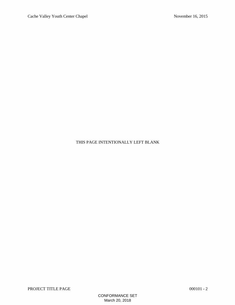
DOCUMENT 000115 - LIST OF DRAWING SHEETS
1.1 LIST OF DRAWINGS
A. Drawings: Drawings consist of the Contract Drawings and other drawings listed on the Table of
Contents page of the separately bound drawing set titled Interfaith Youth Chapel – Cache
Valley Youth Center, dated November 16, 2015, as modified by subsequent Addenda and
Contract modifications.
B. List of Drawings: Drawings consist of the following Contract Drawings and other drawings of
type indicated:
1. GENERAL:
G001 COVER SHEET
G002 GENERAL INFORMATION
2. CIVIL:
C101 SITE DEMOLITION PLAN
C201 SITE PLAN
C401 GRADING PLAN
3. STRUCTURAL:
S001 GENERAL STRUCTURAL NOTES
S002 GENERAL STRUCTURAL NOTES
S101 FOOTING & FOUNDATION PLAN
S102 ROOF FRAMING PLAN
S501 TYPICAL STRUCTURAL DETAILS
S502 STRUCTURAL DETAILS
S503 STRUCTURAL DETAILS
4. ARCHITECTURAL:
AS101 ARCHITECTURAL SITE PLAN
A101 FLOOR PLAN
A121 ROOF PLAN
A151 REFLECTED CEILING PLAN
A201 BUILDING ELEVATIONS
A202 BUILDING ELEVATIONS
A203 BUILDING ELEVATION
A501 ARCHITECTURAL DETAILS
A502 ARCHITECTURAL DETAILS
A503 ARCHITECTURAL DETAILS
5. MECHANICAL:
M001 MECHANICAL SCHEDULES, LEGENDS AND NOTES
M101 MECHANICAL ROOF PLAN
M201 MECHANICAL FLOOR PLAN
M601 MECHANICAL AND PLUMBING DETAILS
CONFORMANCE SETMarch 20, 2018
Cache Valley Youth Center Chapel November 16, 2015
LIST OF DRAWING SHEETS 000115 - 2
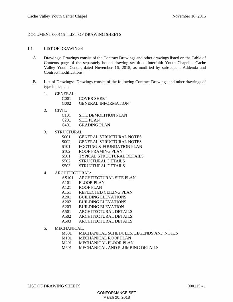
6. ELECTRICAL:
E100 ELECTRICAL NOTES AND SYMBOLS
E201 POWER PLAN
E301 LIGHTING PLAN
E401 ONE LINE DIAGRAMS
E501 ELECTRICAL DETAILS
END OF DOCUMENT 000115
CONFORMANCE SETMarch 20, 2018

DFCM Project No. ________ DFCM Contract No. ______
DFCM FORM 010213 1
DFCM AND DESIGN/BUILD TEAM
AGREEMENT THIS AGREEMENT made and entered into this _____ day of ____, 20__, by and between the DIVISION OF FACILITIES CONSTRUCTION AND MANAGEMENT, hereinafter referred to as the "DFCM", and (FILL IN DESIGN/BUILD FIRM) _____________________, a corporation authorized to do business in the State of Utah and consisting of a legally recognized business entity in the State of Utah and general contracting/ construction management and architectural/engineering components, which are to be performed by (FILL IN DESIGN/BUILD FIRM) _____________________, or entities under contract with (FILL IN DESIGN/BUILD FIRM) _______________, as appropriate. (FILL IN DESIGN/ BUILD FIRM) _____________________, shall hereinafter be referred to as "DESIGN/BUILD TEAM". WITNESSETH: WHEREAS, DFCM intends to have Work performed at _____________________________ _____________________________ _____________________________ WHEREAS, DESIGN/BUILD TEAM agrees to perform the Work for the sum stated herein. NOW, THEREFORE, DFCM and DESIGN/BUILD TEAM for the consideration provided in this Agreement, agree as follows: INTRODUCTION: This Agreement is between DFCM and DESIGN/BUILD TEAM, consisting of the prime general contractor who shall also responsibly represent it’s A/E’s, architect’s, engineer’s, suppliers, consultants, subconsultants and subcontractors at any tier. There are designer and general contractor responsibilities identified in this Agreement. There are important documents incorporated by reference. While the DESIGN/BUILD TEAM maintains liability for all design and general contractor functions, the specific functions referred to in this Agreement as well as the documents incorporated by reference, shall be performed by the respective personnel of the DESIGN/ BUILD TEAM that are qualified architects/engineers and general contractors. The identity of the leaders of the specific functions of the DESIGN/BUILD TEAM are attached to this Agreement, entitled Exhibit “A.” and made a part of this Agreement. Said leadership shall not be changed or substituted without written approval of the DFCM.
ARTICLE 1. DOCUMENTS INCORPORATED BY REFERENCE
AND GENERAL PROVISIONS 1.1 DOCUMENTS INCORPORATED BY REFERENCE:
1.1.1 Request for Proposals and General Conditions. The DESIGN/ BUILD TEAM and DFCM shall be bound by their respective obligations, duties and rights as referred to in the Request for Proposals
CONFORMANCE SETMarch 20, 2018

DFCM Project No. ________ DFCM Contract No. ______
DFCM FORM 010213 2
identified as "Announcement of Design/Build Competition for the Design and Construction of the (FILL IN TITLE OF RFP DOCUMENT) _____________________________________, herein after identified as “Announcement of Design/Build Competition” and dated ___________, inclusive of all addenda, as well as the DFCM General Conditions dated May 25, 2005 (“General Conditions”) and the DFCM Supplemental General Conditions (“also referred to as the DFCM General Conditions”), (www.dfcm.utah.gov/dfcm-forms.html) and on file with the Division of Facilities Construction and Management and by this reference incorporated herein. The Cost Proposal Form is hereby attached and made part of this agreement and is entitled Exhibit “B". It is intended that this DESIGN/BUILD TEAM's Agreement not reiterate all the applicable provisions of said Request for Proposals and the General Conditions and the fact that some provisions are reiterated herein does not lessen the importance of the provisions that are not so reiterated. Unless the context provides otherwise, all the definitions and interpretations of provisions of this DESIGN/BUILD TEAM's Agreement shall be as stated in said Announcement of Design Build Competition and the General Conditions. In case of conflict between the provisions of this DESIGN/BUILD TEAM's Agreement, the Announcement of Design/Build and the General Conditions, the following shall indicate which provision controls:
(1) This Agreement shall control over conflicting provisions in the Announcement of Design/Build Competition and/or General Conditions.
(2) The Announcement of Design/Build Competition shall control over conflicting provisions in the General Conditions. Said General Conditions shall be construed in such a manner as that any reference to a right, responsibility, or duty of the General Contractor (Contractor) referred to in the General Conditions shall be deemed to refer to the DESIGN/BUILD TEAM. Any reference to A/E in the General Conditions shall be deemed to refer to the DESIGN/BUILD TEAM Architect/Engineer as applicable, and shall also be bound by the provisions in the General Conditions that refer to the duties and responsibilities of the A/E in the General Conditions. Unless otherwise specified by this Agreement, the definitions in the General Conditions shall apply to this Agreement.
1.1.2 The Project Defined. The Project is the total design and construction for which the DESIGN/BUILD TEAM is responsible, including all professional design services and all labor, materials and equipment used or incorporated in such design and construction for the project referenced by the Announcement of Design/Build Competition in Paragraph 1.1.1 above. .
1.1.3 The Work Defined. The Work comprises the completed construction designed under the Project and includes labor necessary to produce such construction, and materials and equipment incorporated or to be incorporated in such construction. 1.2 EXECUTION, CORRELATION, CONTRACTUAL RELATIONSHIP AND INTENT
1.2.1 This Agreement shall be signed in not less than duplicate by the DFCM and DESIGN/ BUILD TEAM.
1.2.2 Nothing contained in this Agreement and the Contract Documents shall create a professional obligation or contractual relationship between the DFCM and any third party, including subcontractors, A/E’s, consultants and suppliers at any tier of the DESIGN/BUILD TEAM.
CONFORMANCE SETMarch 20, 2018
DFCM Project No. ________ DFCM Contract No. ______
DFCM FORM 010213 3
Notwithstanding this, it is understood and agreed that the DFCM is the intended third party beneficiary of all contracts for design or engineering services, all subcontracts, purchase orders and other agreements between the DESIGN/BUILD TEAM and third parties. The DESIGN/BUILD TEAM shall incorporate the obligations of this Agreement into its respective subcontracts, supply agreements and purchase orders. The DESIGN/BUILD TEAM shall also be responsible to the DFCM for wrongful or negligent acts, errors or omissions of it’s A/E, consultants, subcontractors, suppliers, agents and employees or those in privity with the DESIGN/BUILD TEAM, at any tier. 1.3 CONTRACT DOCUMENTS. The Contract Documents consist of the General Conditions adopted by the Utah State Building Board on May 25, 2005; the current DFCM Design Manual on file with the office of DFCM; this Agreement; the Conditions of the Contract (General and Supplementary Conditions); and all competition documents provided by DFCM to DESIGN/BUILD TEAM and all competition documents provided by DESIGN/BUILD TEAM to DFCM, which are identified in a list entitled Exhibit “C”, hereby attached and made part of this Agreement. Clarifications to said proposal documents are hereby identified in Exhibit “D”, which is hereby attached and made part of this Agreement. All such Contract Documents referred to in this Paragraph 1.3 are hereby incorporated by reference herein. Any reference in this Agreement to certain provisions of the Contract Documents shall in no way be construed as to lessen the importance or applicability of any other provisions of the Contract Documents. 1.4 CONTRACT DOCUMENTS COMPLIANCE, TERMS, INDEPENDENT CONTRACTOR. The Work to be performed shall be in accordance with all of the Contract Documents. All terms used in this Agreement shall be as defined in the Contract Documents, and in particular, the General Conditions, except as otherwise provided in this Agreement. The DESIGN/ BUILD TEAM Agrees to furnish labor, materials and equipment to complete the Work as required in the Contract Documents which are hereby incorporated by reference. It is understood and agreed by the parties hereto that all Work shall be performed as required in the Contract Documents and shall be subject to inspection and approval of DFCM or its authorized representative. The relationship of the DESIGN/BUILD TEAM to the DFCM hereunder is that of an independent contractor.
ARTICLE 2. DESIGN/BUILD TEAM
2.1 RESPONSIBILITY ALLOCATION. The components of the Design Team shall have primary responsibilities as follows: 2.1.1 Design services shall be performed by the A/E of the DESIGN/BUILD TEAM as well as the appropriate consultants (engineers, etc) selected and paid by the DESIGN/BUILD TEAM and acting in the interest of the DESIGN/BUILD TEAM. As part of the proposal of DESIGN/ BUILD TEAM, (FILL IN NAME OF DESIGN FIRM) __________________ has been selected as the A/E for the Project and is, or shall be promptly, under contract with the DESIGN/BUILD TEAM. DESIGN/BUILD TEAM shall notify DFCM of any substantial change in the composition of the A/E assigned to the Project, including but not limited to any major changes of staffing or assignments of architects to the Project. Any substantial change in the composition of the A/E must be approved by DFCM in writing. The identity of the leader of the specific functions of (FILL IN NAME OF DESIGN FIRM) _____________________ is (FILL IN NAME OF DESIGN FIRM REPRESENTATIVE) ___________________, principal in charge of
CONFORMANCE SETMarch 20, 2018

DFCM Project No. ________ DFCM Contract No. ______
DFCM FORM 010213 4
coordination of all design services. Said leadership shall not be changed or substituted without written approval of the DFCM.
2.1.2 Construction shall be performed in accordance with this Agreement and the Contract Documents by the qualified general contractor component of the DESIGN/BUILD TEAM as well as the appropriate subcontractors and suppliers at any tier in privity with the DESIGN/BUILD TEAM. Design Work shall be performed in accordance with this Agreement and the Contract Documents by the A/E component of the DESIGN/BUILD TEAM as well as the appropriate consultants at any tier in privity with the A/E.
2.1.3 The DESIGN/BUILD TEAM shall be responsible to the DFCM for wrongful or negligent acts, errors or omissions of the DESIGN/BUILD TEAM's employees and parties in privity of contract with the DESIGN/BUILD TEAM, at any tier, to perform any portion of the Work, including their agents and employees.
2.2 BASIC DESIGN SERVICES. The DESIGN/BUILD TEAM's Basic Design Services consist of those described below and any other services identified in this DESIGN/BUILD TEAM Agreement as part of Basic Services related to design, including normal structural, mechanical, electrical, and architectural as well as other consulting services reasonably necessary to fulfill the design duties and responsibilities under this Agreement and the Contract Documents. The DESIGN/BUILD TEAM shall prepare and promptly distribute minutes of all meetings. Said minutes shall not be considered official minutes until approved by the DFCM. 2.3 DESIGN DEVELOPMENT PHASE.
2.3.1 Design Development Documents. Based on the approved Design/Build Proposal, written
authorization to proceed to Design Development signed by the DFCM, and any adjustments authorized by the DFCM in the program, or scope of work, schedule or construction budget, the DESIGN/BUILD TEAM shall prepare, for approval by the DFCM, Design Development Documents consisting of drawings and other documents to fix and describe the size and character of the Project as to architectural, structural, mechanical and electrical systems, materials and such other elements as may be appropriate. The Design Development Documents shall include the items listed in the Design Development Phase Checklist of the DFCM Design Manual incorporated by reference into this Agreement.
2.3.2 Design Revisions. The DFCM reserves the right to request minor design revisions and the DESIGN/BUILD TEAM shall promptly perform such revisions with no increase in cost beyond the Guaranteed Fixed Costs for all the Work of this Project. 2.4 CONSTRUCTION DOCUMENTS PHASE.
2.4.1 Construction Documents. Based on the approved Design Development Documents, and written authorization to proceed to the Construction Documents Phase signed by the DFCM, and any further adjustments in the scope or quality of the Project or in the construction budget authorized by the DFCM, the DESIGN/BUILD TEAM shall prepare, for approval by the DFCM, Construction Documents consisting of Drawings and Specifications setting forth in detail the requirements for the construction of the Project. The Construction Documents shall include the items listed in the Contract Document Phase Checklist of the DFCM Design Manual incorporated by reference into this Agreement.
CONFORMANCE SETMarch 20, 2018
DFCM Project No. ________ DFCM Contract No. ______
DFCM FORM 010213 5
2.4.2 Market Changes. It is understood that the DESIGN/BUILD TEAM assumes the risk and cost of market changes with respect to the DESIGN/BUILD TEAM’s scope of work. In the event any supplier under a Purchase Agreement with the State of Utah fails to perform according to the terms of his agreement, the DESIGN/BUILD TEAM will be entitled to an equitable adjustment of the contract price and time. The DESIGN/BUILD TEAM will use its best efforts in managing those suppliers to maintain the project schedule.
2.4.3 Assist With Filing For Governmental Approval. When requested by the DFCM, the DESIGN/BUILD TEAM shall assist the DFCM in all reasonable requests in connection with the DFCM’s responsibility for filing documents required for approval of governmental authorities having jurisdiction over the Project. 2.5 BIDDING OR NEGOTIATION PHASE. 2.5.1 Duties; In General. After receipt of the written authorization to proceed to the Bidding or Negotiation Phase by DFCM, the DESIGN/BUILD TEAM shall obtain bids or negotiate proposals and award contracts to subcontractors, subconsultants and suppliers which are consistent with the Design/Build Agreement. The term “bid” in the Agreement is also meant to mean “proposal” where the DESIGN/BUILD TEAM is using a request for proposal procurement process.
(1) The DESIGN/BUILD TEAM shall promptly supply ten (10) complete sets of Final Construction Documents to DFCM.
(2) Specified Subcontractors: The specifically cited subcontractors, along with their license number (if required) and estimated cost, have been listed as a submission with the DESIGN/ BUILD TEAM cost proposal. Any substantial variation from the original estimate, submitted on (FILL IN DATE PROPOSAL WAS SUBMITTED) ____________ as part of the Cost Proposal, shall be accompanied by a written explanation from the Contractor justifying the variation and describing how the variation meets or exceeds the “value” to the DFCM on the project. (3) Non-Specified Subcontractors: The non-specified subcontractor’s scope of work and estimated costs shall be listed as a submission with the DESIGN/BUILD TEAM cost proposal. Within 24 hours after the Contractor “opens” the non-specified subcontractors bid and if the bid is from a subcontractor that would otherwise be required to be part of a sublist under UCA 63-5a-208 if the procurement was performed directly by DFCM in bidding process, the DESIGN/BUILD TEAM shall submit name of the subcontractor along with their license number (if required) and estimated cost to DFCM. During the competitive bid process by the DESIGN/BUILD TEAM for these subcontractors, DFCM shall have a representative at the bid opening and subcontractor’s selection.
(4) The DESIGN/BUILD TEAM shall at all reasonable times be available personally, or have available, a responsible member of his or her staff to make such interpretations of the Contract Documents as are necessary to facilitate completion of the construction contract by the DESIGN/BUILD TEAM's subcontractors and suppliers.
(5) If subcontractor’s are selected through a proposal process and the DESIGN/
BUILD TEAM fails to comply with the sublist requirements of UCA 63-5a-208 for bids made applicable in this Agreement to proposals, the DESIGN/BUILD TEAM shall have 24 hours to cure such failure after receiving written notice from DFCM.
CONFORMANCE SETMarch 20, 2018
DFCM Project No. ________ DFCM Contract No. ______
DFCM FORM 010213 6
2.6 CONSTRUCTION PHASE-ADMINISTRATION OF THE CONSTRUCTION.
2.6.1 Advise And Consult. The DESIGN/BUILD TEAM shall advise and consult with the DFCM during the Construction Phase. No one shall be entitled to rely upon any representation by the DESIGN/BUILD TEAM unless it is in writing and signed by the DESIGN/BUILD TEAM Project Manager or a principal of the DESIGN/BUILD TEAM.
2.6.2 Representations by Third Parties, and Officials, Other Than DFCM. DESIGN/
BUILD TEAM may not rely on any representations of other state agencies, officials or any third parties unless specifically approved in writing by DFCM.
2.6.3 Record Copy at Site. The DESIGN/BUILD TEAM shall maintain in good order at the site one record copy of the drawings, specifications, product data, samples, shop drawings, Change Orders and other Modifications, marked currently to record changes made during construction. At the conclusion of the Construction Phase the DESIGN/BUILD TEAM shall prepare and furnish to the DFCM a complete set of Record Drawings (corrected original tracings or re-plotted CADD drawings), one set of mylar reproducible Record Drawings and two (2) sets of Specifications depicting the Project. CADD Criteria. The “DFCM CADD Criteria” which is a part of the Design Manual shall be reviewed by the A/E and shall be used to define and/or supplement any terms or responsibilities under this Agreement. The DFCM CADD Criteria in the Design Manual in case of conflict, shall supersede any provision of this Agreement. 2.7 ADDITIONAL SERVICES: IN GENERAL.
2.7.1 Written Authorization Required. The DESIGN/BUILD TEAM shall perform all duties and responsibilities required by this Agreement and the Contract Documents for the Guaranteed Fixed Price. If the DESIGN/BUILD TEAM reasonably believes that a particular duty or responsibility is beyond that identified by this Agreement or the Contract Documents, then the DESIGN/ BUILD TEAM shall not be entitled to any amount which would result in an increase in the Guaranteed Fixed Price unless, prior to performing the subject duty or responsibility, the DESIGN/BUILD TEAM has requested in writing a Modification to this Agreement and the Modification has been approved, in writing, by DFCM. The provisions of the General Conditions regarding Modifications, requests for additional time and additional monies shall apply to this Agreement.
2.7.2 When Not Paid by DFCM. Notwithstanding anything to the contrary in this Agreement, DFCM shall not be responsible to pay and the DESIGN/BUILD TEAM shall not be entitled to receive, compensation for any Contingent Additional Services if such services were required due to the fault of the DESIGN/BUILD TEAM or the DESIGN/BUILD TEAM's failure to perform in accordance with the terms of this Agreement. Notwithstanding this, there shall be no right to payment for additional services or contingent additional services if such services are not approved in advance by DFCM in writing. 2.8 STANDARD FOR PERFORMANCE.
2.8.1 Due Care and Diligence; In General. DESIGN/BUILD TEAM shall exercise the degree of skill and diligence as exercised by members of the DESIGN BUILD TEAM’S profession having substantial experience on projects similar in type, magnitude and complexity to the Project that is the
CONFORMANCE SETMarch 20, 2018

DFCM Project No. ________ DFCM Contract No. ______
DFCM FORM 010213 7
subject of this Agreement and all of the services under this Agreement shall be performed as expeditiously as is consistent with said standards. The DESIGN/BUILD TEAM shall be liable to the Owner for claims, liabilities, additional burdens, penalties, damages or third party claims, to the extent caused by wrongful or negligent acts, errors or omissions that do not meet this standard of care.
2.8.2 Due Care and Diligence; Discovering and Reporting Defects and Deficiencies. The DESIGN/BUILD TEAM shall exercise due care and diligence in discovering and promptly reporting to the DFCM any defects or deficiencies in the Work. Any defective Designs or Specifications furnished by the DESIGN/BUILD TEAM shall be promptly corrected by the DESIGN/ BUILD TEAM at no cost to the DFCM, and the DESIGN/BUILD TEAM shall promptly reimburse the DFCM for all damages, if any, resulting from the use of such defective Designs or Specifications. The DFCM's approval, acceptance, use of or payment for all or any part of the DESIGN/ BUILD TEAM'S services hereunder or of the Project itself shall in no way alter the DESIGN/BUILD TEAM'S obligations or the DFCM's rights hereunder. 2.9 TESTS, INSPECTIONS AND REPORTS.
2.9.1 DFCM shall be responsible for all structural (soils and concrete), mechanical, electrical testing required by law or code. It shall be DESIGN/BUILD TEAM's responsibility to determine when, which, and to the extent that such tests, inspections and reports are required by the Contract Documents. The DFCM may review and comment, when appropriate, on the accuracy of the tests and information furnished by the DESIGN/BUILD TEAM pursuant to this Paragraph 2.9.1. The DFCM will be monitoring tests and inspections for the subject work. The DESIGN/BUILD TEAM shall coordinate all test and inspections with the DFCM. All other tests or inspections required by contract documents shall be furnished at the DESIGN/BUILD TEAM’s expense. 2.9.2 The DFCM shall be responsible for all chemical, air and water pollution tests, tests for hazardous material, and other laboratory and environmental tests, inspections and reports, including those required by law or the Contract Documents. It shall be DFCM’s responsibility to determine when, which, and to the extent that such tests, inspections and reports are required by the Contract Documents. The DFCM may review and comment, when appropriate, on the accuracy of the tests and information furnished by the DESIGN/BUILD TEAM pursuant to this Paragraph 2.9.2. The services, information, surveys and reports required by this Paragraph 2.9.2 shall be furnished at the DFCM’s expense. The DFCM will be monitoring tests and inspections for the subject work. The DESIGN/BUILD TEAM shall coordinate all test and inspections with the DFCM.
ARTICLE 3.
DFCM'S RESPONSIBILITIES 3.1 INFORMATION. The DFCM shall provide full information regarding requirements for the Project, including a program or scope of work which shall set forth the DFCM's objectives, schedule, constraints, and criteria, including space requirements and relationships, flexibility, expandability, special equipment, systems and site requirements. 3.2 RESPONSE TO DESIGN/BUILD TEAM. The DFCM shall give reasonable consideration to all sketches, estimates, working drawings, specifications, proposals, and other documents presented by the
CONFORMANCE SETMarch 20, 2018
DFCM Project No. ________ DFCM Contract No. ______
DFCM FORM 010213 8
DESIGN/BUILD TEAM; and to inform the DESIGN/BUILD TEAM of the decisions, in writing, within a fourteen (14) day time period. 3.3 DFCM PROJECT MANAGER. The DFCM shall designate a DFCM Project Manager authorized to act on the DFCM's behalf with respect to the Project. The DFCM or such Project Manager shall render decisions within a fourteen (14) day time period pertaining to documents submitted by the DESIGN/BUILD TEAM in order to avoid unreasonable delay in the orderly and sequential progress of the DESIGN/BUILD TEAM's services and Work. The DFCM may appoint an on-site project representative to observe the Work and to have such other responsibilities as the DFCM deems necessary to facilitate this Agreement. 3.4 COMMUNICATIONS. DFCM shall communicate with subcontractors at any tier and material suppliers of the DESIGN/BUILD TEAM only through the DESIGN/BUILD TEAM. DESIGN/BUILD TEAM shall communicate to DFCM directly and not through the User or any other governmental agency. DESIGN/BUILD TEAM shall not rely on any comments or writings of User without express consent in writing of DFCM.
ARTICLE 4. TIME
4.1 DESIGN FUNCTION SCHEDULE. Time limits provided by the RFP shall not be exceeded by the DESIGN/BUILD TEAM or DFCM. Any extensions of time from the schedule shall be void and of no force and effect until such adjustments are agreed to in writing by the DFCM and DESIGN/BUILD TEAM. 4.2 CONSTRUCTION FUNCTION SCHEDULE. TIME OF COMPLETION OF CONSTRUCTION WORK AND DELAY REMEDY. The Construction Work shall be Substantially Complete by (FILL IN COMPLETION DATE) _____________ . DESIGN/BUILD TEAM agrees to pay liquidated damages in the amount of $________ per day for each day after expiration of the Contract Time until the DESIGN/BUILD TEAM achieves Substantial Completion in accordance with the Contract Documents, if the DESIGN/BUILD TEAM’s delay makes the damages applicable. The provision for liquidated damages is: (a) to compensate the DFCM for delay only; (b) is provided for herein because actual damages can not be readily ascertained at the time of execution of this Design/Build Agreement; (c) is not a penalty; and (d) shall not prevent the DFCM from maintaining Claims for other non-delay damages, such as costs to complete or remedy defective Work. No PRE, Claim or action shall be maintained by the DESIGN/BUILD TEAM or Subcontractor or material supplier of DESIGN/BUILD TEAM at any tier, against the DFCM for damages or other claims due to losses attributable to hindrances or delays from any cause whatsoever, including acts and omissions of the DFCM or its officers, employees or agents, except as expressly provided in the General Conditions, including procedural, timing and substantive provisions of the General Conditions.
ARTICLE 5. PAYMENTS
5.1 COMPENSATION. The DFCM shall compensate the DESIGN/BUILD TEAM for work properly performed in accordance with the Contract Documents after the DFCM's receipt and approval of the DESIGN/BUILD TEAM's detailed monthly statement and any lien waivers or releases previously requested by DFCM.
CONFORMANCE SETMarch 20, 2018

DFCM Project No. ________ DFCM Contract No. ______
DFCM FORM 010213 9
5.1.1 Guaranteed Fixed Contract Amount. The DFCM agrees to pay and the
DESIGN/BUILD TEAM agrees to accept in full performance of the design work and the construction Work under this DESIGN/BUILD TEAM's Agreement, not more than the sum of (FILL IN CONTRACT AMOUNT) ____________________________ DOLLARS AND NO CENTS ($__________.00) which sum is the proposal amount submitted on ______________ and which sum shall be the guaranteed fixed contract amount. Payment to the DESIGN/BUILD TEAM will be made within thirty (30) calendar days of receipt of payment application by DFCM. The DESIGN/BUILD TEAM shall provide DFCM within thirty (30) days of request by DFCM, a schedule of accounts and budgets for Work which will be used as a basis for applications for payment. The DFCM agrees to pay the DESIGN/BUILD TEAM for the construction Work and the design services from time to time as the Work progresses, but not more than once each month after the date of Notice to Proceed, and only upon Certificate of the A/E as approved by DFCM which approval may not be unreasonably withheld, for Work performed during the preceding calendar month, ninety-five percent (95%) of the value of the labor performed and ninety-five percent (95%) of the value of materials furnished in place or on the site. The DESIGN/BUILD TEAM agrees to furnish to the DFCM invoices for materials purchased and on the site but not installed, for which the DESIGN/BUILDER requests payment and agrees to safeguard and protect such equipment or materials and is responsible for the safekeeping thereof and if such be stolen, lost or destroyed, to replace same. Such evidence of labor performed and materials furnished as the DFCM may reasonably require shall be supplied by the DESIGN/BUILD TEAM at the time of request for Certificate of Payment on account. Materials for which payment has been made cannot be removed from the job site without DFCM's written approval. Five percent (5%) of the earned amount shall be retained from each monthly payment. Additional retainage shall be imposed if, in the written opinion of the Director of the Division of Facilities Construction and Management, special circumstances or considerations justify the imposition of additional retainage in the interest of the State.
5.1.2 DESIGN/BUILD TEAM Expenses. The guaranteed fixed contract amount shall include all expenses of the DESIGN/BUILD TEAM, including travel, lodging, per diem and other costs associated with the performance of the duties and work under this Agreement. 5.2 DESIGN/BUILD TEAM'S ACCOUNTING RECORDS. All Accounting Records shall be available to the DFCM or the DFCM’s authorized representative at mutually convenient times.
ARTICLE 6. CHANGES IN THE WORK
6.1 ADDITIONAL WORK. It is understood and agreed by the parties hereto that no money will be paid to the DESIGN/BUILD TEAM for additional labor or materials furnished unless a new contract in writing or a Modification hereof in accordance with the General Conditions and Contract Documents for such additional labor or materials has been executed. The DFCM specifically reserves the right to modify or amend this Agreement and the total sum due hereunder either by enlarging or restricting the scope of the Work. Modifications shall be issued in accordance with the General Conditions. No action, conduct, omission, prior failure or course of dealing by the DFCM shall act to waive, modify, change, or alter this requirement. Written modifications are the exclusive method for effecting any change to the contract sum or contract
CONFORMANCE SETMarch 20, 2018

DFCM Project No. ________ DFCM Contract No. ______
DFCM FORM 010213 10
time. The DESIGN/BUILD TEAM understands and agrees that the contract sum and contract time cannot be changed by implication, oral agreements, actions, inactions, course of conduct or contractor initiated change order.
ARTICLE 7. INSURANCE, BONDS AND INDEMNIFICATION
7.1 IN GENERAL. To protect against liability, loss and/or expense arising in connection with the performance of services described under this DESIGN/BUILD TEAM's Agreement, the DESIGN/BUILD TEAM shall obtain and maintain in force during the entire period of this DESIGN/BUILD TEAM's Agreement, at its own expense, the following insurance from insurance companies authorized to do business in the State of Utah and rated "A" or better with a financial size category of Class X or larger. An exception to the above-stated rating and financial size category requirements is for the professional liability insurance referred to in 7.2.1(1) below, in which case the rating must be "B" or better with a financial size category of Class VIII or larger. All said ratings and financial size categories shall be as published by A.M. Best Company at the time this DESIGN/BUILD TEAM's Agreement is executed. 7.2 DESIGN/BUILD TEAM INSURANCE. Insurance for the general construction management and architectural components of the DESIGN/BUILD TEAM shall be provided as required below:
7.2.1 General Contractor’s Insurance. In addition to the insurance required in Section 7.4 below, the DESIGN/BUILD TEAM shall meet all the insurance requirements for a General Contractors as required by the General Conditions. 7.3 GENERAL CONTRACTOR'S BONDS. In addition to the insurance required above, the bonds for the General Contractor functions under this Agreement shall be provided as required by the General Conditions. The 100% performance and payment bonds may exclude the amount attributable to design services as agreed to by DFCM. The performance and payment bonds must be in effect and provided to DFCM on the standard DFCM forms prior to the issuance of a notice to proceed for the actual construction work. 7.4 DESIGN INSURANCE. In addition to the insurance required above, the following insurance for the design services under this Agreement shall be provided:
7.4.1 DESIGN/BUILD TEAM Designer's Professional Liability Insurance. The DESIGN/ BUILD TEAM shall maintain a professional liability insurance policy on a claims made basis, annual aggregate policy limit based on the following chart, unless modified in an attachment to this Agreement.
Construction Budget Minimum Liability Coverage
$50,000,000 and above $2,000,000 per claim, $4,000,000 aggregate $25,000,000 and above, but under $50,000,000 $2,000,000 per claim, $2,000,000 aggregate $1,500,000 and above but under $25,000,000 $1,000,000 per claim, $1,000,000 aggregate Under $1,500,000 $ 500,000 per claim, $ 500,000 aggregate
CONFORMANCE SETMarch 20, 2018

DFCM Project No. ________ DFCM Contract No. ______
DFCM FORM 010213 11
7.4.2 Valuable papers and Records Coverage and/or Electronic Data Processing (Data and Media) Coverage. The DESIGN/BUILD TEAM and all engineering consultants of the DESIGN/BUILD TEAM shall provide coverage for the physical loss of or destruction to their work product including drawings, specifications and electronic data and media.
7.5 ADDITIONAL COVERAGE. The DFCM reserves the right to require additional coverage from that stated hereinabove, at the DFCM's expense for the additional coverage portion only. DFCM also reserves the right to require project specific insurance, and if such right has been exercised it shall be indicated as an exhibit to this DESIGN/BUILD TEAM's Agreement. Unless project specific insurance is required by the DFCM, the coverage may be written under a practice policy with limits applicable to all projects undertaken by the firm but must be maintained in force for the discovery of claims for a period of three (3) years after the date final payment is made to the DESIGN/BUILD TEAM under this DESIGN/ BUILD TEAM's Agreement. All policies provided by the DESIGN/BUILD TEAM must contain a "retroactive" or "prior-acts" date which precedes the earlier of, the date of the DESIGN/BUILD TEAM's Agreement or the commencement of the DESIGN/BUILD TEAM's services. The DESIGN/BUILD TEAM's policy must also include a contractual liability endorsement applicable to the indemnity provision contained under this Article of this DESIGN/ BUILD TEAM's Agreement. Any review and approval by the DFCM does not relieve the DESIGN/BUILD TEAM of any responsibility of liability for an error, omission, submittal or work. 7.6 FURNISH EVIDENCE OF INSURANCE, CERTIFICATES, ADDITIONAL INSURED. The DESIGN/BUILD TEAM shall submit certificates in form and substance satisfactory to the DFCM as evidence of the insurance requirements of this Article. Such certificates shall provide the DFCM with thirty (30) days notice prior to the cancellation, material change or non-renewal of the applicable coverage, as evidenced by return receipt, certified mail, sent to DFCM. The DESIGN/BUILD TEAM shall notify DFCM within thirty (30) days of any claim(s) against the DESIGN/BUILD TEAM which singly or in the aggregate exceed 20% of the applicable required insured limits, and the DFCM may require the DESIGN/BUILD TEAM to reinstate the policy to provide full protection at the original limits. The State of Utah shall be named as an insured party, as primary coverage and not contributing, on all the insurance policies required by this Article except the professional liability and workers' compensation policies. The DFCM reserves the right to request the DESIGN/BUILD TEAM to provide a loss report from their insurance carrier. 7.7 DFCM RECOURSE. The DESIGN/BUILD TEAM agrees to maintain the insurance described in this Article during the required term. If the DESIGN/BUILD TEAM fails to furnish and maintain said required insurance, the DFCM may purchase such insurance on behalf of the DESIGN/BUILD TEAM, and the DESIGN/BUILD TEAM shall pay the cost thereof to the DFCM upon demand and shall furnish to the DFCM any information needed to obtain such insurance. 7.8 INDEMNIFICATION.
7.8.1 In General. To the fullest extent permitted by law, the DESIGN/BUILD TEAM shall indemnify and hold harmless the State of Utah, its institutions, agencies, departments, divisions, authorities, and instrumentalities, boards, commissions, elected or appointed officers, employees, agents, authorized volunteers (hereinafter the above listing of entities and persons is referred to as "indemnities") from and against every kind and character of claims, damages, losses and expenses, including but not limited to
CONFORMANCE SETMarch 20, 2018

DFCM Project No. ________ DFCM Contract No. ______
DFCM FORM 010213 12
attorneys' fees, arising out of or resulting from any act or omission in the performance of the Work under this DESIGN/ BUILD TEAM's Agreement including the work of anyone directly or indirectly employed by the DESIGN/ BUILD TEAM, the DESIGN/BUILD TEAM's agent, consultant or independent contractor, or anyone for whose acts any of them may be liable, provided that any such claim, damage, loss or expense is caused in whole or in part by the negligent or intentional act or omission of the DESIGN/BUILD TEAM, anyone directly or indirectly employed by the DESIGN/BUILD TEAM, the agent, consultant or independent contractor of any of them or anyone for whose acts any of them may be liable, regardless of whether or not it is caused in part by a part indemnified hereunder. The DESIGN/ BUILD TEAM shall defend all actions brought upon such matters to be indemnified hereunder and pay all costs and expenses incidental thereto, but the State of Utah shall have the right, at its option, to participate in the defense of any such action without relieving the DESIGN/BUILD TEAM of any obligation hereunder.
7.8.2 Not Reduce Current Rights. Such obligation shall not be construed to negate, abridge, or otherwise reduce any other right or obligation of indemnity which would otherwise exist as to any party or person under this DESIGN/BUILD TEAM's Agreement.
7.8.3 Not Bound By Damage Limitations Under Certain Acts. In claims against any person or entity indemnified under this Paragraph 7.8 by an employee of the DESIGN/BUILD TEAM, anyone directly or indirectly employed by the DESIGN/BUILD TEAM, the agent, consultant or independent contractor of any of them or anyone for whose acts any of them may be liable, the indemnification obligation under this Paragraph 7.8 shall not be limited by a limitation on the amount or type of damages, compensation or benefits payable by or for the DESIGN/BUILD TEAM or said employee, agent, consultant, independent contractor or anyone for whose acts any of them may be liable, under workers' or workmen's compensation acts, disability benefits acts or other employee benefit acts.
ARTICLE 8. DISPUTE RESOLUTION
8.1 DISPUTES. Any dispute, PRE or Claim between the parties shall be subject to the provisions of Article 7 of the General Conditions. DFCM reserves all rights to pursue its rights and remedies as provided in the General Conditions.
ARTICLE 9. TERMINATION, SUSPENSION OR ABANDONMENT
9.1 IN GENERAL. This Agreement may be terminated, suspended or abandoned in accordance with the General Conditions.
ARTICLE 10. OWNERSHIP AND USE OF DRAWINGS,
SPECIFICATIONS AND OTHER DOCUMENTS 10.1 IN GENERAL. All Drawings, Specifications, other Contract Documents, as well as studies and projects prepared by the DESIGN/BUILD TEAM under this Agreement, are and shall remain the property of the DFCM, and DFCM shall retain all common law, statutory and other reserved rights with respect thereto. All other provisions regarding the use, re-use and other provision regarding such items as stated in the General Conditions shall apply.
CONFORMANCE SETMarch 20, 2018

DFCM Project No. ________ DFCM Contract No. ______
DFCM FORM 010213 13
ARTICLE 11. MISCELLANEOUS PROVISIONS
11.1 GOVERNING LAW AND VENUE. Unless otherwise provided, this DESIGN/BUILD TEAM's Agreement shall be governed by the laws of the State of Utah. Salt Lake County, State of Utah, shall be the venue of any legal proceeding regarding the terms or enforcement of this DESIGN/BUILD TEAM's Agreement. 11.2 WAIVER TO EXTENT OF RECOVERY OF INSURANCE MONIES. The DFCM and DESIGN/BUILD TEAM waive all rights against each other and against the DESIGN/BUILD TEAM's consultants, subcontractors, agents and employees of the other for damages, but only to the extent covered by the DFCM provided Builder's Risk Policy concerning damage to the Work during construction, except such rights as they may have to the proceeds of such insurance as set forth in the General Conditions. The DFCM and DESIGN/BUILD TEAM each shall require similar waivers from their contractors, subcontractors, consultants and agents at any tier. 11.3 BINDING AGREEMENT AND ASSIGNMENT PROVISIONS. The DFCM and DESIGN/ BUILD TEAM respectively, bind themselves, their successors, assigns and legal representatives to the other party to this DESIGN/BUILD TEAM's Agreement and to the partners, successors, assigns and legal representatives of such other party with respect to all covenants of this DESIGN/BUILD TEAM's Agreement. Neither the DFCM nor the DESIGN/BUILD TEAM shall assign its interest in this Agreement without the written consent of the other, except that the Contractor hereby consents to the assignment of the DFCM's interest herein as provided in this Article 11. 11.4 INTEGRATION AND AMENDMENT. This DESIGN/BUILD TEAM's Agreement represents the entire and integrated agreement between the DFCM and DESIGN/BUILD TEAM and supersedes all prior negotiations, representations or agreements, either written or oral. Except for Construction Change Directives issued under the General Conditions, this Agreement may be amended only by written instrument signed by both DFCM and DESIGN/BUILD TEAM. 11.5 THIRD PARTIES. Except for DFCM’s third party beneficiary rights described in this Agreement, nothing contained in this Agreement shall create a contractual relationship with or a cause of action in favor of a third party against either the DFCM or DESIGN/BUILD TEAM. 11.6 HAZARDOUS MATERIALS. The responsibilities of the DFCM and the DESIGN/BUILD TEAM regarding Hazardous Materials shall be as specified in the General Conditions and the Contract Documents. 11.7 PROMOTION. The DESIGN/BUILD TEAM shall have the right to include accurate representations of the design of the Project, including photographs of the exterior and interior, among the DESIGN/BUILD TEAM's promotional and professional materials. The DESIGN/BUILD TEAM's materials shall not include the DFCM's or the State’s confidential or proprietary information if the DFCM has previously advised the DESIGN/BUILD TEAM in writing of the specific information considered by the DFCM to be confidential or proprietary. The DFCM shall provide professional credit for the DESIGN/ BUILD TEAM on the construction sign and in the promotional materials for the Project. For purposes of this Paragraph 11.7, reference to the "DESIGN/BUILD TEAM" shall include the DESIGN/BUILD TEAM's consultants.
CONFORMANCE SETMarch 20, 2018

DFCM Project No. ________ DFCM Contract No. ______
DFCM FORM 010213 14
11.8 INDEPENDENT CONTRACTOR. The DESIGN/BUILD TEAM shall be considered an independent DESIGN/BUILD TEAM, and as such, shall have no authorization, express or implied, to bind the State of Utah or the DFCM to any agreement, settlement, liability or understanding whatsoever, nor to perform any acts as agent for the State of Utah or DFCM, except as specifically set forth in this DESIGN/BUILD TEAM's Agreement. 11.9 WRITTEN NOTICE. DFCM and DESIGN/BUILD TEAM shall be subject to the written notice provisions of the General Conditions. 11.10 DFCM/AGENCY REVIEW. DFCM or any other entity’s (including agency user’s of the State of Utah) plan reviews or any other type or nature of review shall in no way relieve the DESIGN/BUILD TEAM of design liability or contractual responsibility under this DESIGN/BUILD TEAM's Agreement. Any guidelines, specifications, drawings or plans provided by the DFCM or any other entity to the DESIGN/ BUILD TEAM shall not relieve the DESIGN/BUILD TEAM of design liability or contractual responsibility under this Agreement. 11.11 CONSULTANTS. 11.11.1 Not Use "Sales" or "Agent" A/E’s or Consultants. The DESIGN/ BUILD TEAM agrees not to use "sales" or "agent" A/E’s or consultants. Said A/E’s or Consultants are not to benefit financially either directly or indirectly from the sale or use of any product on or in the Project.
11.11.2 A/E and Consultant Qualifications. All A/E and Consultants must be licensed in Utah for the professional practice used on the Project and be approved in writing, in advance, by the DFCM. 11.12 A/E, CONSULTANTS, SUBCONTRACTORS OF DESIGN/BUILD TEAM. Any A/E, subcontract, supplier, or consultants agreement that the DESIGN/BUILD TEAM may enter into in regard to the Project of this DESIGN/BUILD TEAM's Agreement, shall require conformance with the provisions of this DESIGN/ BUILD TEAM's Agreement, to the extent applicable. 11.13 WORK BY DFCM OR DFCM'S CONTRACTORS. The DFCM reserves the right to perform work related to, but not part of, the Project and to award separate contracts in connection with other work at the site. The DESIGN/BUILD TEAM shall cooperate with the DFCM to afford the DFCM's other contractors a reasonable opportunity for access and storage of their materials and equipment for execution of their work. The DESIGN/BUILD TEAM shall incorporate and coordinate the DESIGN/BUILD TEAM's Work with work of the DFCM's separate contractors as required by the Contract Documents. The DESIGN/BUILD TEAM shall promptly notify the DFCM if any such independent action will in any way compromise the DESIGN/ BUILD TEAM's ability to meet the DESIGN/BUILD TEAM's responsibilities under this Agreement. 11.14 SEVERABILITY. In case a provision of this Agreement is held to be invalid, illegal or unenforceable, the validity, legality and enforceability of the remaining provisions shall not be affected. 11.15 OBSERVATIONS. The Work shall be observed for acceptance in accordance with the General Conditions. DESIGN/BUILD TEAM shall have a Utah duly licensed architect or engineer, visit the site at least once per week during construction and shall make appropriate observations and promptly write and send to the DFCM written reports for each site visit. DFCM may request more periodic site observations by
CONFORMANCE SETMarch 20, 2018
DFCM Project No. ________ DFCM Contract No. ______
DFCM FORM 010213 15
the A/E if needed. The A/E shall be compensated for additional work properly performed and approved in advance in writing by DFCM as well as not caused by errors and/or omissions of DESIGN/BUILD TEAM. The A/E shall report promptly any deficiencies, defects or problems with the Work or site conditions. 11.16 RELATIONSHIP OF THE PARTIES AND ASSIGNMENT. The DESIGN/BUILD TEAM accepts the relationship of trust and confidence established by this DESIGN/BUILD TEAM's Agreement and covenants with the DFCM to cooperate with the DFCM and utilize the DESIGN/ BUILD TEAM's best skill, efforts and judgment in furthering the interest of the DFCM; to furnish efficient business administration and supervision; to make best efforts to furnish at all times an adequate supply of workers and materials; and to perform the Work in the best and most expeditious and economic manner consistent with the interests of the DFCM. 11.17 SUCCESSORS AND ASSIGNS. The DFCM and DESIGN/BUILD TEAM, respectively bind themselves, their partners, successors, assigns and legal representatives to the other party to this Agreement, and to partners, successors, assigns and legal representatives of such other party with respect to all covenants, provisions, rights and responsibilities of this Agreement. The DESIGN/BUILD TEAM shall not assign the Contract without the prior written consent of the DFCM, nor shall the DESIGN/BUILD TEAM assign any moneys due or to become due as well as any rights under the Contract, without prior written consent of the DFCM. The DFCM agrees to exercise reasonable best efforts to enable the DESIGN/BUILD TEAM to perform the Work by furnishing and approving in a timely way, information required by the DESIGN/BUILD TEAM in accordance with the requirements of the Contract Documents. 11.18 AUTHORITY TO EXECUTE AND PERFORM AGREEMENT. DESIGN/BUILD TEAM and DFCM each represent that the execution of this DESIGN/BUILD TEAM's Agreement and the performance thereunder is within their respective duly authorized powers. 11.19 ATTORNEY FEES AND COSTS. Except as otherwise provided in the dispute resolution provisions of the General Conditions, the prevailing party shall be entitled to reasonable attorney fees and costs incurred in any action in the District Court and/or appellate body to enforce this DESIGN/BUILD TEAM's Agreement or recover damages or any other action as a result of a breach thereof. 11.20 EXTENT OF AGREEMENT. This Agreement represents the entire agreement between the DFCM and DESIGN/BUILD TEAM and supersedes any prior negotiations, representations or agreements. This Agreement may be amended only by written instrument signed by both DFCM and DESIGN/BUILD TEAM. The DESIGN/BUILD TEAM and DFCM for themselves, their heirs, successors, executors, and administrators, whichever may be applicable, hereby agree to the full performance of this Agreement and the Contract Documents. DESIGN/BUILD TEAM and DFCM each represent that the execution of this DESIGN/BUILD TEAM's Agreement and the performance thereunder is within their respective duly authorized powers.
CONFORMANCE SETMarch 20, 2018

DFCM Project No. ________ DFCM Contract No. ______
DFCM FORM 010213 16
IN WITNESS WHEREOF, the parties hereto have executed this DESIGN/BUILD TEAM's Agreement on the day and year stated hereinabove. D/B TEAM: Signature Date Title: State of _____________) ) ss. County of _____________) Please type/print name clearly On this ____ day of _________, 20____, personally appeared before me, __________________, whose identity is personally known to me (or proved to me on the basis of satisfactory evidence) and who by me duly sworn (or affirmed), did say that he (she) is the ________________ (title or office) of the firm and that said document was signed by him (her) in behalf of said firm. _____________________________ Notary Public (SEAL) My Commission Expires _________ APPROVED AS TO AVAILABILITY DIVISION OF FACILITIES OF FUNDS: CONSTRUCTION AND MANAGEMENT */S/ David D. Williams, Jr._____________ */S/ Region Director David D. Williams, Jr. Region Director CBA Financial Director APPROVED AS TO FORM: APPROVED FOR EXPENDITURE: ATTORNEY GENERAL January 2, 2013 */S/ Division of Finance By: Alan S. Bachman Division of Finance Asst Attorney General *Electronic signatures are effective when the AIM Status History page is attached to this agreement following this signature page. The AIM Status History page identifies the State signatures.
CONFORMANCE SETMarch 20, 2018

DFCM Project No. ________ DFCM Contract No. ______
DFCM FORM 010213 17
EXHIBIT “A”
DESIGN/BUILD TEAM Leaders
CONFORMANCE SETMarch 20, 2018

DFCM Project No. ________ DFCM Contract No. ______
DFCM FORM 010213 18
EXHIBIT “B” Cost Proposal Form with Cost Breakdown
CONFORMANCE SETMarch 20, 2018
DFCM Project No. ________ DFCM Contract No. ______
DFCM FORM 010213 19
EXHIBIT “C”
List of Competition Documents
CONFORMANCE SETMarch 20, 2018
DFCM Project No. ________ DFCM Contract No. ______
DFCM FORM 010213 20
EXHIBIT “D” Clarification Items
CONFORMANCE SETMarch 20, 2018
DFCM General Conditions 052505 i
G E N E R A L C O N D I T I O N S
May 25, 2005
Table of Contents
ARTICLE 1. GENERAL PROVISIONS. 1.1 Basic Definitions. ARTICLE 2. DFCM. 2.1 Information and Services Required of the
DFCM. 2.1.1 DFCM’s Representative. 2.1.2 Specialists and Inspectors. 2.1.3 Surveys and Legal Description. 2.1.4 Prompt Information and Services. 2.1.5 Copies of Drawings and Project
Manuals (For Construction). 2.1.6 Other Duties. 2.2 Construction By DFCM or By Separate Contractors
2.2.1 DFCM’s Right To Perform Construction and to Award Separate Contracts. (1) In General. (2) Coordination and Revisions.
2.2.2 Mutual Responsibility. (1) Contractor Coordination. (2) Reporting Problems to
DFCM. (3) Costs. (4) Contractor Remedial Work.
ARTICLE 3. A/E 3.1 A/E's Administration of the Contract.
3.1.1 In General. 3.1.2 Site Visits. 3.1.3 Communications Facilitating
Contract Administration. 3.1.4 A/E May Reject Work, Order
Inspection, Tests. 3.1.5 A/E Review Contractor's Submittals.
3.2 Ownership and Use of A/E's Drawings, Specifications and Other Documents.
ARTICLE 4. CONTRACTOR 4.1 Review of Contract Documents and Field
Conditions By Contractor. 4.1.1 Reviewing Contract Documents,
Information, Reporting Errors, Inconsistencies or Omissions.
4.1.2 Field Conditions. 4.1.3 Perform in Accordance with
Contract Documents and Submittals. 4.1.4 Performance to Produce the Complete
System and Intended Results. 4.1.5 Intent and Hierarchy. 4.1.6 Dividing Work and Contractor
Representation. 4.1.7 Planning and Priority.
4.2 Supervision and Construction Procedures. 4.2.1 Supervision and Control. 4.2.2 Responsibility. 4.2.3 Not Relieved of Obligations. 4.2.4 Inspections and Approvals.
4.3 Labor and Materials. 4.3.1 Payment by Contractor. 4.3.2 Discipline and Competence.
4.4 Taxes and Other Payments to Government. 4.5 Permits, Fees, Notices, Labor and Materials.
4.5.1 Permits and Fees. 4.5.2 Compliance With Public Authorities,
Notices. 4.5.3 Correlation of Contract Documents
and Enactments.
STATE OF UTAH - DEPARTMENT OF ADMINISTRATIVE SERVICES
Division of Facilities Construction and Management DFCM
CONFORMANCE SETMarch 20, 2018

DFCM General Conditions 052505 ii
4.5.4 Failure to Give Notice. 4.6 Superintendent. 4.7 Time and Contractor's Construction
Schedules. 4.7.1 Progress and Completion. (1) Time Is of the Essence;
Complete Within Contract Time.
(2) Notice to Proceed and Insurance.
4.7.2 Schedule Preparation. 4.7.3 Initial Contract Time. 4.7.4 Interim Completion Dates and
Milestones. 4.7.5 Schedule Content Requirements. 4.7.6 DFCM's Right to Take Exceptions. 4.7.7 Float Time. 4.7.8 Initial Schedule Submission. 4.7.9 Updates. 4.7.10 Schedule of Submittals. 4.7.11 Schedule Recovery. 4.7.12 Schedule Changes and
Modifications. (1) Contract Time Change
Requires Modification. (2) Contractor Reordering,
Resequencing and Changing Activity Durations.
(3) Changes In Contract Time. 4.7.13 Excusable Delay.
(1) In General. (2) Weather-Related Excusable
Delays. 4.7.14 Compensable Delay, Suspension or
Interruption. (1) Basic Conditions.
(2) Compensable Delay Formula.
(3) Period of Compensable Delay, Suspension or Interruption
(4) Concurrent Delay. 4.7.15 Time Extension Requests. 4.7.16 Liquidated Damages.
(1) In General. (2) No Waiver of DFCM’s
Rights. 4.8 Documents and Samples at the Site,
Certifying "As-Builts". 4.9 Shop Drawings, Product Data and Samples.
4.9.1 Not Contract Documents. 4.9.2 Promptness. 4.9.3 Not Perform Until A/E Approves. 4.9.4 Representations by Contractor. 4.9.5 Contractor's Liability. 4.9.6 Direct Specific Attention to
Revisions.
4.9.7 Informational Submittals. 4.9.8 Reliance on Professional
Certification. 4.10 Use of Site.
4.10.1 In General. 4.10.2 Access to Neighboring Properties.
4.11 Access to Work. 4.12 Royalties and Patents. 4.13 Indemnification.
4.13.1 In General. ARTICLE 5. SUBCONTRACTORS. 5.1 Award of Subcontracts and Other Contracts
For Portions of the Work. 5.1.1 Approval Required. 5.1.2 Business and Licensing
Requirements. 5.1.3 Subsequent Changes. 5.1.4 Bonding of Subcontractors.
5.2 Subcontractual Relations. 5.2.1 Comply With Contract Documents. 5.2.2 Rights. 5.2.3 Sub-Subcontractors. 5.2.4 Document Copies.
5.3 Contingent Assignment of Subcontracts. 5.3.1 Conditions for Assignment to DFCM.
ARTICLE 6. PROTECTION OF PERSONS AND PROPERTY. 6.1 Safety of Persons and Property.
6.1.1 Contractor Responsibility. 6.1.2 Safety Program, Precautions. 6.1.3 Compliance With Laws. 6.1.4 Erect and Maintain Safeguards. 6.1.5 Utmost Care. 6.1.6 Prompt Remedy. 6.1.7 Safety Designee. 6.1.8 Load Safety. 6.1.9 Off-Site Responsibility. 6.1.10 Emergencies.
6.2 Hazardous Materials. 6.3 Historical and Archeological Considerations. 6.4 Contractor Liability. ARTICLE 7. MODIFICATIONS, REQUEST FOR INFORMATION, PROPOSED CHANGE ORDER, PRELIMINARY RESOLUTION EFFORTS AND CLAIMS PROCESS. 7.1 Modifications: In General.
7.1.1 Types of Modifications and Limitations.
7.1.2 By Whom Issued. 7.1.3 Contractor to Proceed Unless
Otherwise Stated. 7.1.4 Adjusting Unit Prices.
CONFORMANCE SETMarch 20, 2018
DFCM General Conditions 052505 iii
7.1.5 Special Notices Required In Order to Be Eligible For Any Contract Modification.
(1) Concealed or Unknown Conditions.
(2) Increase in Contract Time. 7.2 Contractor Initiated Requests.
7.2.1 The Request for Information, RFI, Process and Time to File.
7.2.2 Proposed Change Order (“PCO”). 7.3 Proposal Request Initiated by DFCM.
7.3.1 If Agreement, Change Order Issued. 7.3.2 If Disagreement.
7.4 Evaluation of Proposal For Issuing Change Orders. 7.4.1 Adjusting Sum Based Upon
Agreement. 7.4.2 DFCM Resolution of Sum and
Standards in the Absence of an Agreement Under Paragraph 7.4.1.
7.4.3 Credits. 7.5 Construction Change Directives.
7.5.1 When Used and Contractor’s Right to Challenge.
7.5.2 Proceed With Work and Notify DFCM About Adjustment Method.
7.5.3 Interim Payments by DFCM. 7.6 A/E’s Supplemental Instruction 7.7 Procedure For Preliminary Resolution
Efforts. 7.7.1 Request For Preliminary Resolution
Effort (Pre). 7.7.2 Time For Filing. 7.7.3 Content Requirement. 7.7.4 Supplementation. 7.7.5 Subcontractors. 7.7.6 Pre Resolution Procedure. 7.7.7 Contractor Required to Continue
Performance. 7.7.8 Decision. 7.7.9 Decision Final Unless Claim
Submitted. 7.7.10 Extension Requires Mutual
Agreement. 7.7.11 If Decision Not Issued.
7.7.12 Payment for Performance. 7.8 Resolution of Claim.
7.8.1 Claim. 7.8.2 Subcontractors. 7.8.3 Time for Filing. 7.8.4 Content Requirement. 7.8.5 Extension of Time to Submit
Documentation. 7.8.6 Contractor Required to Continue
Performance. 7.8.7 Agreement of Claimant on Method
and Person(s) Evaluating the Claim. 7.8.8 The Evaluation Process,
7.8.9 Timeframes of Evaluator(s), Director’s Determination, Administrative Appeal to the Executive Director and Judicial Review.
7.8.9 Appeal Process Prerequisite for Further Consideration or Judicial Review.
7.9 Payment of Claim. 7.10 Allocation of Costs of Claim Resolution
Process. 7.11 Alternative Procedures. 7.12 Impact on Future Selections. 7.13 Report to Building Board. 7.14 DFCM’s Right to Have Issues, Disputes or
Claims Considered ARTICLE 8. PAYMENTS AND COMPLETION. 8.1 Schedule of Values. 8.2 Applications for Payment. 8.2.1 In General. 8.2.2 Payment for Material and Equipment. 8.2.3 Warranty of Title. 8.2.4 Holdback by DFCM. 8.3 Certificates for Payment. 8.3.1 Issued by A/E. 8.3.2 A/E's Representations. 8.4 Decisions to Withhold Certification. 8.4.1 When Withheld. 8.4.2 Certification Issued When Reasons For Withholding Removed. 8.4.3 Continue Work Even if Contractor
Disputes A/E's Determination. 8.4.4 DFCM Not in Breach. 8.5 Progress Payments. 8.5.1 In General, Interest on Late
Payments. 8.5.2 Contractor and Subcontractor
Responsibility. 8.5.3 Information Furnished by A/E or
DFCM to Subcontractor. 8.5.4 DFCM and A/E Not Liable. 8.5.5 Certificate, Payment or Use Not
Acceptance of Improper Work. 8.6 Payment Upon Substantial Completion. 8.7 Partial Occupancy or Use.
8.7.1 In General. 8.7.2 Inspection. 8.7.3 Not Constitute Acceptance.
8.8 Final Payment. 8.8.1 Certificate for Payment. 8.8.2 Conditions for Final Payment. 8.8.3 Waiver of Claims: Final Payment. 8.8.4 Delays Not Contractor's Fault. 8.8.5 Waiver by Accepting Final
Payment.
CONFORMANCE SETMarch 20, 2018

DFCM General Conditions 052505 iv
ARTICLE 9. TESTS AND INSPECTIONS, SUBSTANTIAL AND FINAL COMPLETION, UNCOVERING, CORRECTION OF WORK AND GUARANTY PERIOD. 9.1 Tests and Inspections.
9.1.1 In General. 9.1.2 Failure of an Inspector to Appear.
9.1.3 Nonconforming Work. 9.1.4 Certificates. 9.1.5 A/E Observing. 9.1.6 Promptness.
9.2 Inspections: Substantial and Final. 9.2.1 Substantial Completion Inspection.
9.2.2 Final Completion Inspection. 9.3 Uncovering of Work.
9.3.1 Uncover Uninspected Work. 9.3.2 Observation Prior to Covering.
9.3.3 When an Inspector Fails to Appear or A/E or DFCM Did Not Make Prior Request.
9.4 Correction of Work and Guaranty Period. 9.4.1 Contractor Correct the Work. 9.4.2 Guaranty and Correction After
Substantial Completion. 9.4.3 Removal of Work.
9.4.4 Not Limit Other Obligations. 9.5 Additional Warranties. 9.5.1 In General.
9.5.2 Exclusion. 9.5.3 Furnish Evidence on Request.
9.6 Acceptance of Nonconforming Work. ARTICLE 10. INSURANCE AND BONDS. 10.1 Liability Insurance. 10.1.1 In General.
10.1.2 Configurations. 10.1.3 Contractor Liability. 10.1.4 Certificate, Notice Requirements,
Additional Insured. 10.1.5 Deductible Liability. 10.1.6 Additional Requirements:
10.2 "Builder's Risk" Property Insurance. 10.2.1 In General. 10.2.2 Inspections, Recommendations. 10.2.3 Deductible. 10.2.4 Adjusted With and Payable to Risk
Manager as Trustee. 10.2.5 Waiver. 10.2.6 Special Hazards.
10.3 Performance Bond and Payment Bond. ARTICLE 11. MISCELLANEOUS PROVISIONS. 11.1 A/E's Responsibilities. 11.2 Successors and Assigns. 11.3 Written Notice. 11.3.1 Personal Delivery and Registered or
Certified Mail.
11.3.2 Fax. 11.4 Rights and Remedies. 11.4.1 Not Limit. 11.4.2 Not Waiver. 11.5 Commencement of Statutory Limitation
Period. 11.5.1 Before Substantial Completion. 12.5.2 Between Substantial Completion
and Final Certification for Payment. 11.5.3 After Final Certification for Payment. 11.5.4 Exception. 11.6 Not Discriminate, No Sexual Harassment. 11.7 Applicable Laws. 11.8 Interpretation. 11.9 Venue. 11.10 Severability. 11.11 Construction of Words. 11.12 No Third Party Rights. ARTICLE 12. TERMINATION OR SUSPENSION OF THE CONTRACT. 12.1 Termination by Contractor. 12.1.1 In General. 12.1.2 Notice. 12.2 Termination by the DFCM for Cause. 12.2.1 In General. 12.2.2 DFCM's Right to Carry Out the
Work. 12.2.3 Items Required to Be Transferred or
Delivered. 12.2.4 Payment. 12.2.5 DFCM Protection if Lienable. 12.2.6 Credits and Deficits. 12.2.7 If Contractor Found Not in Default
or Excusable. 12.2.8 Rights and Remedies Not Exclusive. 12.3 Suspension, Delay or Interruption of Work by
the DFCM for Convenience. 12.3.1 By DFCM in Writing. 12.3.2 Time Period for Claims. 12.3.3 Adjustments. 12.4 Termination for Convenience of the DFCM. 12.4.1 In General. 12.4.2 Contractor Obligations. 12.4.3 Termination Claim. 12.4.4 Agreed Upon Payment. 12.4.5 Payment Not Agreed Upon.
12.4.6 Deductions. 12.4.7 Partial Termination. 12.4.8 Partial Payments. 12.4.9 Preserve and Make Available
Records. 12.5 DFCM’s Right to Stop the Work.
CONFORMANCE SETMarch 20, 2018

DFCM General Conditions 052505 1
G E N E R A L C O N D I T I O N S
May 25, 2005 ARTICLE 1. GENERAL PROVISIONS. 1.1 BASIC DEFINITIONS. A/E (including all design professionals). "A/E" means the person lawfully licensed to practice architecture or engineering or an entity lawfully practicing architecture or engineering identified as such in the A/E's Agreement and is referred to throughout the Contract Documents as if singular in number. The term "A/E" also means the A/E's representative and its subconsultants. When these General Conditions are part of a Contract in which the design professional is an interior designer, landscape subconsultant or other design professional, the term "A/E" as used in these General Conditions shall be deemed to refer to such design professional. A license is not required when the type of design professional is one which is not subject to a professional license, but such professional must meet the prevailing standards in the State of Utah for such practice. For projects where there is no A/E hired by DFCM, the references in the General Conditions to A/E shall be deemed to refer to DFCM as may be practicably applied. ADDENDA. "Addenda" means the written or graphic instruments issued prior to the opening of Bids which clarify, correct or change the bidding documents or the Contract Documents. ASI. “ASI” shall mean a Supplemental Instruction issued by the A/E to the Contractor which may result in clarifications or minor changes in the Work and does not affect the contract time or the contract amount.
BID. "Bid" means the offer or proposal of the bidder submitted on the prescribed form setting forth the prices for the Work to be performed. BONDS. "Bonds" mean the bid bond, performance and payment bonds and other instruments of security. CHANGE ORDER. "Change Order" means a written instrument signed by the DFCM and Contractor, stating their agreement for changes of the Contract as specified on the required DFCM’s change order form. CLAIM. “Claim” means a dispute, demand, assertion or other matter submitted by the Contractor, including a Subcontractor at any tier subject to the provisions of these General Conditions. The claimant may seek, as a matter of right, modification, adjustment or interpretation of Contract terms, payment of money, extension of time or other relief with respect to the terms of the Contract. A request for Preliminary Resolution Effort (PRE) shall not be considered a “Claim.” A requested amendment, requested change order, or a Construction Change Directive (CCD) is not a PRE or Claim unless agreement cannot be reached and the procedures of these General Conditions are followed. CONSTRUCTION CHANGE DIRECTIVE. A "Construction Change Directive" means a written order signed by the DFCM, directing a change in the Work and stating a proposed basis for adjustment, if any, in the Contract Sum or Contract Time, or both. The DFCM may by Construction Change Directive, without
STATE OF UTAH - DEPARTMENT OF ADMINISTRATIVE SERVICES
Division of Facilities Construction and Management DFCM
CONFORMANCE SETMarch 20, 2018

DFCM General Conditions 052505 2
invalidating the Contract, order changes in the Work within the general scope of the Contract consisting of additions, deletions or other revisions; even if it may impact the Contract Sum and Contract Time. CONTRACT. The Contract Documents form the Contract for Construction. The term "Contract" represents the entire and integrated agreement between the parties hereto and supersedes prior negotiations, representations or agreements, either written or oral. The Contract Documents shall not be construed to create a contractual relationship of any kind (1) between the A/E and Contractor, (2) between the DFCM and a Subcontractor or (3) between any persons or entities other than the DFCM and Contractor. CONTRACT DOCUMENTS. The term "Contract Documents" means the Contractor's Agreement between the DFCM and Contractor (hereinafter referred to as "Contractor's Agreement"), the Conditions of the Contract (General, Supplementary and other Conditions), the Drawings, Specifications, Addenda, other documents listed in the Contractor's Agreement and Modifications issued after execution of the Contractor's Agreement. The Contract Documents shall also include the bidding/proposal documents, including the Instructions to Bidders/Proposers, Notice to Contractors and the Bid/Proposal Form, to the extent not in conflict with the other above-stated Contract Documents and other documents and oral presentations as part of the Selection which are documented as an attachment to the Contract. CONTRACT SUM. The term "Contract Sum" means the Contract Sum as stated in the Contractor's Agreement and, including authorized and signed adjustments to this agreement (modifications), is the total amount payable by the DFCM to the Contractor for performance of the Work under the Contract Documents. CONTRACT TIME. "Contract Time", unless otherwise provided in the Contract Documents, means the period of time, including authorized and signed adjustments (modifications), stated in the Contract Documents for Substantial Completion of the Work.
CONTRACTOR. The Contractor is the person or entity identified as such in the DFCM Contractor's Agreement and is referred to throughout the Contract Documents as if singular in number. The term "Contractor" means the Contractor or the Contractor's authorized representative. When separate contracts are awarded for different portions of the Project or other construction or operations on the site, the term "Contractor" in the Contract Documents in each case, shall mean the Contractor who executes each separate DFCM Contractor Agreement. CONTRACTOR’S AGREEMENT. “Contractor’s Agreement” means, unless the context requires otherwise, the agreement executed by the Contractor and DFCM for the Project. DAY. The term "day" or “days” as used in the Contract Documents shall mean calendar day unless otherwise specifically defined. DEFECTIVE. "Defective" is an adjective which when modifying the word "Work" refers to Work that does not conform to the Contract Documents, or does not meet the requirements of any inspection, referenced standard, code, test or approval referred to in the Contract Documents, or has been damaged. DFCM REPRESENTATIVE. “DFCM Representative” means the Division of Facilities Construction and Management person directly assigned to work with the Contractor on a regular basis. Unless the context requires otherwise, the “DFCM Representative” is the “Owner’s Representative.” DIRECTOR. “Director” means the Director of the Division of Facilities Construction and Management unless the context requires otherwise. Director may include a designee selected by the Director for the particular function referred to in the General Conditions.
DFCM. “DFCM” means the Division of Facilities Construction and Management established pursuant to Utah Code Annotated Section 63A-5-201 et seq. Unless the context requires otherwise, DFCM is the “Owner” as that term is commonly referred to in the construction industry.
CONFORMANCE SETMarch 20, 2018

DFCM General Conditions 052505 3
DRAWINGS. The "Drawings" are the graphic and pictorial portions of the Contract Documents, wherever located and whenever issued, showing the design, location and dimensions of the Work, and generally include the drawings, elevations, sections, details, schedules and diagrams. EXECUTIVE DIRECTOR. “Executive Director” means the Executive Director of the Department of Administrative Services, including unless otherwise stated, his/her duly authorized designee.
INSPECTION. The word “inspection” or its derivatives shall mean a review of the Project, including but not limited to a visual review of the Work completed to date to ascertain if the Work is in accordance with the Contract Documents, including all applicable building codes and construction standards. MODIFICATION. A "Modification" is (1) a Change Order (2) Construction Change Directive or (3) ASI. The Contract may be amended or modified only by (1) a written amendment executed by both the DFCM and Contractor, or (2) by a Modification. NOTICE TO PROCEED. A "Notice to Proceed" is a document prepared by the DFCM and by its terms authorizes the Contractor to commence Work on the Project. It is deemed issued upon being sent by the DFCM to the Contractor's specified address within the bid or proposal. PARTIAL USE. "Partial Use" means placing a portion of the Work in service for the purpose for which it is intended (or a related purpose) before reaching Substantial Completion for all the Work. This partial use does not constitute "substantial completion".
PRELIMINARY RESOLUTION EFFORT. “Preliminary Resolution Effort” or “PRE” means the processing of a request for preliminary resolution or any similar notice about a problem that could potentially lead to a Claim and is prior to reaching the status of a Claim.
PRODUCT DATA. "Product Data" means illustrations, standard schedules, performance charts, instructions, brochures, diagrams and other information furnished by the Contractor to illustrate materials or equipment for some portion of the Work. PROJECT. The "Project" means the total construction of the Work performed under the Contract Documents. PROJECT MANUAL (FOR CONSTRUCTION). The "Project Manual" is the volume assembled for the Work and may include the bidding/proposal requirements, sample forms, General or Supplementary Conditions of the Contract and Specifications. PROPOSAL REQUEST OR “PR.” A “Proposal Request” or “PR” is a proposal request filed with the Contractor for the purposes of seeking a proposal in order to resolve an issue as part of the Change Order or Contract Modification process. PROPOSED CHANGE ORDER. A “Proposed Change Order” (“PCO”), is an informal request by the Contractor filed with the DFCM Representative, in an effort to commence the Contract Modification Process. It shall not be considered a “PRE” or a “Claim.” The PCO may be related to any potential, or actual delay, disruption, unforeseen condition or materials or any other matter in which the Contractor intends to seek additional monies or time.
REQUEST FOR INFORMATION or RFI. A “Request for Information” or “RFI” is a request filed by the Contractor with the A/E regarding any request for information, direction or clarification related to the Contract Documents, plans or specifications. RESOLUTION OF THE CLAIM. “Resolution of the Claim” means the final resolution of the Claim by the Director, but does not include any administrative appeal, judicial review or judicial appeal thereafter. RULE. “Rule,” unless the context requires otherwise, shall mean a Rule of the Utah Administrative Code.
CONFORMANCE SETMarch 20, 2018

DFCM General Conditions 052505 4
SALES TAX and/or USE TAX. Sales Tax and/or Use Tax, unless the context requires otherwise, shall mean the sales tax and/or use tax collected or to be collected by the Utah State Tax Commission and shall include any sales and/or use tax that the Utah State Tax Commission collects on behalf of any special district, local government or political subdivision. SAMPLES. "Samples" mean physical examples, which illustrate materials, equipment or workmanship and establishes standards by which the Work will be judged. SHOP DRAWINGS. "Shop Drawings" means drawings, diagrams, schedules and other data specially prepared for the Work by the Contractor or a Subcontractor, Sub-subcontractor, manu- facturer, supplier or distributor to illustrate some portion of the Work. SPECIFICATIONS. The "Specifications" are that portion of the Contract Documents consisting of the written requirements for materials, equipment, construction systems, standards, installation and workmanship for the Work, and performance of related systems and services. SUBCONTRACTOR. “Subcontractor” means the person or entity that has a direct contract with the Contractor, including any trade contractor or specialty contractor, or with another Subcontractor at any tier to provide labor or materials for the work but does not include suppliers who provide only materials, equipment or supplies to a contractor or subcontractor. Notwithstanding the foregoing, the text in which the term is used may provide for the exclusion of Subcontractors of other Subcontractors or the exclusion of suppliers. The term “Subcontractor” is referred to throughout the Contract Documents as if singular in number and means a Subcontractor or authorized representative of the Subcontractor. The Term “Subcontractor” does not include a separate contractor or subcontractors of a separate contractor. SUBSTANTIAL COMPLETION. "Substantial Completion" is the date certified in accordance with Article 9.2 and means the date the Work or designated portion thereof is sufficiently complete,
and any lack of completion or performance does not reasonably interfere with the DFCM’s intended use of the Project, in accordance with the Contract Documents so that the DFCM can occupy and use the Work for its intended use. DFCM’s “intended use” or “occupy” as used in this definition, shall include any intended use or occupation by any agency or entity for which DFCM has intended to so occupy the Project. SUPPLEMENTARY CONDITIONS OR SUPPLEMENTARY GENERAL CONDITIONS. "Supplementary Conditions" or "Supplementary General Conditions" means the part of the Contract Documents which amends or supplements these General Conditions. WORK. The term "Work" means the construction and services required by the Contract Documents, whether completed or partially completed, and includes all labor, materials, equipment and services provided, or to be provided, by the Contractor to fulfill the Contractor's obligations. ARTICLE 2. DFCM. 2.1 INFORMATION AND SERVICES REQUIRED OF THE DFCM. 2.1.1 DFCM’S REPRESENTATIVE. The DFCM shall designate a DFCM Representative authorized to act in the DFCM’s behalf with respect to the Project. The DFCM or such authorized representative shall render decisions within a reasonable time pertaining to documents submitted by the A/E and/or Contractor in order to avoid a compensable delay in the orderly and sequential progress of the Project. 2.1.2 SPECIALISTS AND INSPECTORS. The DFCM will provide certified building inspection services in accordance with the adopted Building Codes. This includes 'routine' and 'special' inspections unless otherwise noted in the A/E Agreement. The DFCM may assign an inspector or specialist to note deviations from, or necessary adjustments to, the Contract Documents or to report deficiencies or defects in the Work. The inspector or specialist's activities in no way relieves the
CONFORMANCE SETMarch 20, 2018

DFCM General Conditions 052505 5
Contractor of the responsibilities set forth in the Contract Documents. 2.1.3 SURVEYS AND LEGAL DESCRIPTION. The DFCM shall furnish surveys describing physical characteristics, legal limitations and utility locations for the site of the Project, and a legal description of the site. The Contractor shall review this information, including the surveys and any provided soils tests, and compare such information with observable physical conditions and the Contract Documents. 2.1.4 PROMPT INFORMATION AND SERVICES. Upon receipt of a written request from the Contractor, the DFCM shall furnish information or services under the DFCM’s control with reasonable promptness to avoid delay in the orderly progress of the Work. 2.1.5 COPIES OF DRAWINGS AND PROJECT MANUALS (FOR CONSTRUCTION). Unless otherwise provided in the Contract Documents, the Contractor will be furnished, free of charge, such copies of Drawings and Project Manuals (for construction) as are reasonably necessary for execution of the Work. DFCM’s Web Page may also provide referenced documents for the Project. 2.1.6 OTHER DUTIES. The foregoing is in addition to other duties and responsibilities of the DFCM enumerated herein and especially those in respect to Article 2.2 (Construction by DFCM or by Separate Contractors), Article 8 (Payments and Completion) and Article 10 (Insurance and Bonds). 2.2 CONSTRUCTION BY DFCM OR BY SEPARATE CONTRACTORS
2.2.1 DFCM’S RIGHT TO PERFORM CONSTRUCTION AND TO AWARD SEPARATE CONTRACTS.
(1) IN GENERAL. The DFCM reserves the right to perform construction or operations related to the Project with the DFCM’s own forces, and to award separate contracts in connection with other portions of the Project or other construction or operations on the site under Conditions of the Contract identical or
substantially similar to these including those portions related to insurance and waiver of subrogation.
(2) COORDINATION AND REVISIONS. The DFCM shall provide for coordination of the activities of the DFCM’s own forces and of each separate Contractor with the Work of the Contractor, who shall cooperate with them. The Contractor shall participate with other separate contractors and the DFCM in reviewing their construction schedules when directed to do so. The Contractor shall make any revisions to the construction schedule and Contract Sum deemed necessary after a joint review and agreement by the DFCM. The construction schedules shall then constitute the schedules to be used by the Contractor, separate contractors and the DFCM until subsequently revised.
2.2.2 MUTUAL RESPONSIBILITY.
(1) CONTRACTOR COORDINATION. The Contractor shall afford the DFCM and separate contractor(s) a reasonable opportunity for delivery and storage of their materials and equipment and performance of their activities and shall connect and coordinate the Contractor's construction and operations with theirs as required by the Contract Documents.
(2) REPORTING
PROBLEMS TO DFCM. If part of the Contractor's Work depends on work by the DFCM or a separate contractor, the Contractor shall, prior to proceeding with that portion of the Work, promptly report in writing to the DFCM apparent defects in workmanship that would render it unsuitable for proper execution. Failure of the Contractor to make said report shall constitute an acknowledgment that the DFCM’s or separate contractor's completed or partially completed construction is fit and proper to receive the Contractor's Work, except as to defects in workmanship not then reasonably discoverable.
(3) COSTS. Costs caused by delays or by improperly timed activities or defective construction shall be borne by the responsible party in accordance with the procedures and provisions of the Contract Documents.
CONFORMANCE SETMarch 20, 2018

DFCM General Conditions 052505 6
(4) CONTRACTOR
REMEDIAL WORK. The Contractor shall promptly remedy damage caused by the Contractor to completed or partially completed Work or to property of the DFCM or separate contractors and subcontractors as provided in Article 6. ARTICLE 3. A/E. 3.1 A/E'S ADMINISTRATION OF THE CONTRACT.
3.1.1 IN GENERAL. The A/E assists the DFCM with the administration of the Contract as described in the Contract Documents. The A/E shall have the authority to act on behalf of the DFCM only to the extent provided in the Contract Documents or A/E's Agreement.
3.1.2 SITE VISITS.
(1) Site visits or inspections by the A/E, the DFCM or any DFCM representative shall in no way limit or affect the Contractor's responsibility to comply with all the requirements and the overall design concept of the Contract Documents as well as all applicable laws, statutes, ordinances, resolutions, codes, rules, regulations, orders and decrees. (2) WRITTEN REPORT. The A/E shall promptly submit to the DFCM a written report subsequent to each site visit.
3.1.3 COMMUNICATIONS FACILITATING CONTRACT ADMINISTRATION. Except as authorized by the DFCM Representative or as otherwise provided in the Contract Documents, including these General Conditions, the A/E and Contractor shall communicate through the DFCM Representative on issues regarding the timing of the Work, cost of the Work or scope of the Work. Contractor shall comply with communication policies agreed upon at any pre-construction meeting with the DFCM. Communications by and with the A/E subconsultants shall be through the A/E. Communications by and with Subcontractors shall be through the Contractor. Communications
by and with separate contractors shall be through the DFCM.
3.1.4 A/E MAY REJECT WORK,
ORDER INSPECTION, TESTS. The A/E shall have the responsibility and authority to reject Work which, based upon the A/E’s knowledge or what may be reasonably inferred from the A/E’s site observations and review of data, does not conform to the Contract Documents. Whenever the A/E considers it necessary or advisable for implementation of the intent of the Contract Documents, the A/E shall have the responsibility and authority to require additional inspections or testing of the Work in accordance with the provisions of the Contract Documents, whether or not such Work is fabricated, installed or completed, provided, however, the A/E must obtain the DFCM’s prior written approval of any such additional inspections or testing. However, neither this authority of the A/E nor a decision made in good faith either to exercise or not to exercise such authority shall give rise to a duty or responsibility of the A/E to the Contractor, Subcontractors, their agents or employees or other persons performing portions of the Work, including separate contractors. If the Contractor disputes the rejection of any Work and the correction thereof shall involve additional cost or time, it shall be the DFCM’s option to accept such Work whether it be conforming or nonconforming.
3.1.5 A/E REVIEW CONTRACTOR'S SUBMITTALS. (1) Contractor shall submit shop drawings, product data, and samples and other submittals required by the Contract Documents to the A/E as required by the approved submittal schedule. (2) The A/E shall review and approve or take other appropriate action upon Contractor's submittals such as Shop Drawings, Product Data and Samples, but only for the purpose of checking for conformance with the information and design concepts expressed in the Contract Documents. A/E action taken on a submittal shall not constitute a Modification of this Agreement.
CONFORMANCE SETMarch 20, 2018

DFCM General Conditions 052505 7
(3) The A/E’s action shall be taken no later than 15 days following A/E’s receipt of the submittal, unless agreed to otherwise by Contractor and DFCM, in order to avoid a delay in the Work of the Contractor or of separate contractors while allowing sufficient time in the A/E’s professional judgment to permit adequate review. (4) Review of such submittals is not conducted for the purpose of determining the accuracy and completeness of other details such as dimensions and quantities or for substantiating instructions for installation or performance of equipment or systems, all of which remain the responsibility of the Contractor as required by the Contract Documents. (5) The A/E’s review of the Contractor's submittals shall not relieve the Contractor of the obligations under the Contract Documents. (6) The A/E’s review shall not constitute approval of safety precautions or, unless otherwise specifically stated by the A/E, of any construction means, methods, techniques, sequences or procedures. (7) The A/E’s approval of a specific item shall not indicate approval of an assembly of which the item is a component. (8) When professional certification of performance characteristics of materials, systems or equipment is required by the Contract Documents, the A/E shall be entitled to rely upon such certifications to establish that the materials systems or equipment will meet the performance criteria required by the Contract Documents. 3.2 OWNERSHIP AND USE OF A/E'S DRAWINGS, SPECIFICATIONS AND OTHER DOCUMENTS. All Drawings, Specifications and other documents prepared by the A/E are and shall remain the property of the DFCM, and DFCM shall retain all common law, statutory and other reserved rights with respect thereto. Said documents were prepared and are intended for use as an integrated set for the Project which is the subject of this Contractor's
Agreement. The Contractor shall not modify or use Contract Documents on any other project without the prior written consent of the DFCM and A/E. Any such non-permissive use or modification, by Contractor, the Contractor's Subcontractors at any tier or anyone for whose acts the Contractor is liable, shall be at Contractor's sole risk. Contractor shall hold harmless and indemnify the DFCM from and against any and all claims, actions, suits, costs, damages, loss, expenses and attorney fees arising out of such non-permissive use or modification by the Contractor. The Contractor and Subcontractors are granted a limited license to use and reproduce applicable portions of the Drawings, Specifications and other documents prepared by the A/E appropriate to and for use in the execution of their Work under the Contract Documents. All copies made under this license shall bear the statutory copyright notice, if any, shown on the Drawings, Specifications and other documents prepared by the A/E. Submittals or distributions necessary to meet official regulatory requirements or for other purposes relating to completion of the Project are not to be construed as a publication in derogation of the DFCM's copyright or other reserved rights. ARTICLE 4. CONTRACTOR 4.1 REVIEW OF CONTRACT DOCUMENTS AND FIELD CONDITIONS BY CONTRACTOR.
4.1.1 REVIEWING CONTRACT DOCUMENTS, INFORMATION, REPORTING ERRORS, INCONSISTENCIES OR OMISSIONS. The Contractor shall carefully study and compare the Contract Documents with each other and with information furnished by the DFCM pursuant to Article 2.1 hereinabove and shall at once report to the DFCM and A/E errors, inconsistencies or omissions discovered. The Contractor shall not be liable to the DFCM or A/E for damage resulting from errors, inconsistencies or omission in the Contract Documents, unless the Contractor recognized such error, inconsistency or omission or a Contractor of ordinary skill and expertise for the type of Work involved would have readily so recognized such error, inconsistency or omission, and the Contractor
CONFORMANCE SETMarch 20, 2018

DFCM General Conditions 052505 8
failed to report such to the DFCM and A/E. If the Contractor performs any construction activity without such notice to the DFCM and A/E and prior to the resolution of the error, inconsistency or omission, the Contractor shall assume appropriate responsibility for such performance and shall bear an appropriate amount of the attributable costs for correction. 4.1.2 FIELD CONDITIONS. The Contractor shall take field measurements and verify field conditions and shall carefully compare such field measurements and conditions and other information known to the Contractor, or information which a Contractor of ordinary skill and expertise for the type of Work involved would have known, before commencing activities. Errors, inconsistencies or omissions discovered shall be reported to the DFCM and A/E at once. If the Contractor performs any construction activity without such notice to the DFCM and A/E and prior to the resolution of the error, inconsistency or omission, the Contractor shall assume appropriate responsibility for such performance and shall bear an appropriate amount of the attributable costs for correction. 4.1.3 PERFORM IN ACCORDANCE WITH CONTRACT DOCUMENTS AND SUBMITTALS. The Contractor shall perform the Work in accordance with the Contract Documents and submittals approved in accordance with the Contract Documents 4.1.4 PERFORMANCE TO PRODUCE THE COMPLETE SYSTEM AND INTENDED RESULTS. Performance by the Contractor shall be required to the extent consistent with the Contract Documents and reasonably inferable from the Contract Documents as being necessary to allow the system to function within its intended use. 4.1.5 INTENT AND HIERARCHY. The Contract Documents should be read as a whole and wherever possible, the provisions should be construed in order that all provisions are operable. The intent of the Contract Documents is to include all items necessary for the proper execution and completion of the Work by the Contractor. The Contract Documents are
complimentary, and what is required by one Document or provisions thereof shall be as binding as if required by all the Documents or provisions thereof. In case of an irreconcilable conflict between provisions within a Contract Document or between Contract Documents, the following priorities shall govern as listed below: (1) A particular Modification shall govern over all Contract Document provisions or Modifications issued prior to said particular Modification. (2) Attachments to the Contractor’s Agreement resulting from the Selection process including any management plan or documented interview information shall govern over addenda, the General Conditions, plans and specifications. (3) A particular Addendum shall govern over all other Contract Document provisions issued prior to said particular Addendum. Subsequent Addenda shall govern over all prior Addenda. (4) The Supplementary General Conditions shall govern over the General Conditions. (5) These General Conditions shall govern over all other Contract Documents except for the Supplementary General Conditions, Addenda, Modifications and Attachments resulting from the selection process. (6) The drawings and specifications shall not govern over any of the documents listed above. (7) In case of a conflict or ambiguity within the same level of hierarchy of described documents, DFCM reserves the right to select the most stringent requirement unless the preponderance of the contract indicates the less stringent requirement. 4.1.6 DIVIDING WORK AND CONTRACTOR REPRESENTATION. Organization of the specifications into divisions, sections and articles, and arrangement of Drawings, shall not control the Contractor in
CONFORMANCE SETMarch 20, 2018

DFCM General Conditions 052505 9
dividing the Work among Subcontractors or in establishing the extent of Work to be performed by any trade. Contractor represents that the Subcontractors, Sub-subcontractors, manufacturers and suppliers engaged or to be engaged by it are and will be familiar with the requirements for performance by them of their obligations.
4.1.7 PLANNING AND PRIORITY. The Contractor shall plan and schedule its work to facilitate the Project and shall maintain a work schedule to place proper priority to sequence work to complete the project timely. 4.2 SUPERVISION AND CONSTRUCTION PROCEDURES.
4.2.1 SUPERVISION AND CONTROL. The Contractor shall supervise and direct the Work, using the Contractor's best skill and attention. The Contractor shall be solely responsible for and have control over the construction means, methods, techniques, sequences and procedures and for coordinating all portions of the Work under the Contract, except to the extent that the Contract Documents expressly and specifically state otherwise.
4.2.2 RESPONSIBILITY. The Contractor shall be responsible to the State of Utah and DFCM for acts and omissions of the Contractor's employees, Subcontractors, and their agents and employees, and other persons performing portions of the Work under a contract with the Contractor or on behalf of the Contractor.
4.2.3 NOT RELIEVED OF OBLIGATIONS. The Contractor shall not be relieved of obligations to perform the Work in accordance with the Contract Documents either by activities or duties of the DFCM or its agents in the DFCM's administration of the Contract, or by tests, inspections or approvals required or performed by persons other than the Contractor or for those that the Contractor is liable.
4.2.4 INSPECTIONS AND APPROVALS.
(1) The Contractor is responsible for requesting inspections for various
stages and portions of the Work required under the Contract Documents in a timely manner.
(2) If any of the Work is required to be inspected or approved by the terms of the Contract Documents by any public authority, the Contractor shall timely request such inspection or approval to be performed in accordance with Article 9. Except as provided in Article 9, work shall not proceed without any required inspection and the associated authorization to proceed. Contractor shall promptly notify DFCM if the inspector fails to appear at the site. 4.3 LABOR AND MATERIALS.
4.3.1 PAYMENT BY CONTRACTOR. Except to the extent it is otherwise stated in the Contract Documents, the Contractor shall provide and pay for labor, materials, equipments, tools, construction equipment and machinery, water, heat, utilities, transportation, and other facilities, supplies, consumables and services necessary for the proper execution and completion of the Work, whether temporary or permanent and whether or not incorporated or to be incorporated in the Work.
4.3.2 DISCIPLINE AND COMPETENCE. The Contractor shall enforce strict discipline and good order among the Contractor's employees, its Subcontractors, agents, representatives and other persons performing under the Contract Documents. The Contractor shall not permit employment of unfit persons or persons not skilled in tasks assigned to them. 4.4 TAXES AND OTHER PAYMENTS TO GOVERNMENT. The Contractor shall pay sales, consumer, use, employment-related and similar taxes related to the Work or portions thereof provided by the Contractor which are legally enacted when bids are received or negotiations concluded, whether or not yet effective or merely scheduled to go into effect. The Contractor shall comply with the laws and regulations regarding the payment of Sales and/or Use Tax and any exemptions. The procurement documents may have a provision regarding specific items which are exempt from State of Utah Sales Tax and/or Use Tax. Any such
CONFORMANCE SETMarch 20, 2018

DFCM General Conditions 052505 10
exemption shall be used only for the items and the project specified in the procurement documents. Any such exemption does not apply to taxes levied by the federal government or any taxing entity outside of the State of Utah. If a Contractor properly relies upon a provision(s) of the bidding or proposal documents, and if State of Utah Sales and/or Use Tax subsequently becomes due, then the Contractor shall be paid such tax amount not included in the bid/proposal amount due to the reliance upon such provision. 4.5 PERMITS, FEES, NOTICES, LABOR AND MATERIALS.
4.5.1 PERMITS AND FEES. Unless required in the Supplementary General Conditions or an Addendum, it will not be necessary for the Contractor to obtain or pay for local building permits, plan check fees, electrical permits, plumbing permits, connection fees, or impact fees, nor will it be necessary to pay fees for inspections pertaining thereto.
4.5.2 COMPLIANCE WITH PUBLIC
AUTHORITIES, NOTICES. The Contractor shall comply with and give notices required by laws, ordinances, resolutions, rules, regulations and lawful orders of public authorities bearing on the performance of the Work.
4.5.3 CORRELATION OF CONTRACT DOCUMENTS AND ENACTMENTS. It is not the Contractor's responsibility to ascertain that the Contract Documents are in accordance with applicable laws, statutes, ordinances, resolutions, building codes, and rules and regulations. Notwithstanding this, if the Contractor observes, or if such is readily observable to a Contractor of ordinary skill and expertise for the type of Work involved, that a portion of the Contract Documents is at variance therewith, the Contractor shall promptly notify the A/E and DFCM in writing, and necessary changes shall be accomplished by appropriate Modification.
4.5.4 FAILURE TO GIVE NOTICE. If the Contractor, or any Subcontractor thereof performs Work without complying with the requirements of this Article 4.5 hereinabove, the Contractor shall assume appropriate responsibility
for such Work and shall bear the appropriate amount of the attributable costs. 4.6 SUPERINTENDENT. The Contractor shall employ a competent superintendent and necessary assistants who shall be in attendance at the Project site during performance of the Work. The superintendent shall represent the Contractor, and communications given to the superintendent shall be as binding as if given to the Contractor. Important communications shall be confirmed in writing. Other communications shall be similarly confirmed on written request in each case. 4.7 TIME AND CONTRACTOR'S CONSTRUCTION SCHEDULES.
4.7.1 PROGRESS AND COMPLETION.
(1) TIME IS OF THE ESSENCE; COMPLETE WITHIN CONTRACT TIME. Time is of the essence. By executing the Contractor's Agreement, the Contractor confirms that the Contract Time is adequate to perform the Work. The Contractor shall proceed expeditiously with adequate forces to achieve Substantial Completion within the Contract Time. (2) NOTICE TO PROCEED AND INSURANCE. The Contractor shall not prematurely commence operations on the site or elsewhere prior to the issuance of a Notice to Proceed by the DFCM or prior to the effective date of insurance required by Article 10 to be furnished by the Contractor, whichever is the latter. 4.7.2 SCHEDULE PREPARATION. The Contractor, promptly after being awarded the Contract, shall prepare and submit for the DFCM's and A/E's review, a reasonably detailed CPM schedule for the Work. The schedule shall indicate the order, sequence, and interdependence of all items known to be necessary to complete the Work including construction, procurement, fabrication, and delivery of materials and equipment, submittals and approvals of samples, shop drawings, procedures, or other documents. Work items of the DFCM, other Contractors, utilities and other third parties that may affect or
CONFORMANCE SETMarch 20, 2018

DFCM General Conditions 052505 11
be affected by the Contractor shall be included. If the DFCM is required, by the Contract Documents, to furnish any materials, equipment, or the like, to be incorporated into the Work by the Contractor, Contractor shall submit, with the first schedule submittal, a letter clearly indicating the dates that such items are required at the Project Site. The critical path should be identified, including the critical paths for interim completion dates and milestones. The CPM schedule shall be developed using Primavera, MS Project, or Suretrack unless otherwise authorized by the DFCM Representative. The Contractor's schedule shall be updated at least once a month and submitted with each pay request.
4.7.3 INITIAL CONTRACT TIME.
Unless otherwise specified in the bidding documents, the initial Contract Time is the time identified in the Contractor’s Agreement.
4.7.4 INTERIM COMPLETION DATES AND MILESTONES. The schedule must include contractually specified interim completion dates and milestones. The milestone completion dates indicated are considered essential to the satisfactory performance of this Contract and to the coordination of all Work on the Project. The milestone dates listed are not intended to be a complete listing of all Work under this Contract or of interfaces with other Project Contractors.
4.7.5 SCHEDULE CONTENT REQUIREMENTS. The schedule shall indicate an early completion date for the Project that is no later than the Project's required completion date. The schedule, including all activity duration's shall be given in calendar days. The Schedule shall also indicate all of the following: (1) Interfaces with the work of outside contractors (e.g., utilities, power and with any separate Contractor);
(2) Description of activity including activity number/numbers; (3) Estimated duration time for each activity;
(4) Early start, late start, early finish, late finish date, and predecessor/successors including stop-start relationships with lead and lag time for each activity;
(5) Float available to each path of activities; (6) Actual start date for each activity begun; (7) Actual finish date for each activity completed; (8) The percentage complete of each activity in progress or completed;
(9) Identification of all critical path activities;
(10) The critical path for the Project, with said path of activities being clearly and easily recognizable on the time-scaled network diagram. The path(s) with the least amount of float must be identified. Unless otherwise authorized by the DFCM Representative, no more than 40% of all activities may be identified as critical path items. The relationship between non-critical activities and activities on the critical path shall be clearly shown on the network diagram;
(11) Unless otherwise authorized by the DFCM Representative, all activities on the schedule representing construction on the site may not have a duration longer than 14 days. Construction items that require more than 14 days to complete must be broken into identifiable activities on the schedule with durations less than 14 days. The sum of these activities represents the total length required to complete that construction item; and (12) Additional requirements as specified in the Supplemental General Conditions.
4.7.6 DFCM'S RIGHT TO TAKE EXCEPTIONS. The DFCM reserves the right to take reasonable exception to activity duration, activity placement, construction logic or time frame for any element of the Work to be scheduled.
CONFORMANCE SETMarch 20, 2018
DFCM General Conditions 052505 12
4.7.7 FLOAT TIME. Float or slack
time is defined as the amount of time between the earliest start date and the latest start date or between the earliest finish date and the latest finish date of a chain of activities on the Schedule. By a proposal request or modification delivered to the Contractor, the DFCM has the right to use the float time for non-critical path activities until the Contractor has reallocated such time on a newly submitted schedule.
4.7.8 INITIAL SCHEDULE SUBMISSION. No progress payments will be approved until the Contractor has submitted a Project detailed CPM schedule covering the first 90 days of the Work with a general CPM schedule for the entire project. The detailed schedule for the entire project is to be completed prior to the second pay request unless otherwise authorized in writing by the DFCM Representative.
4.7.9 UPDATES. Prior to any approval of a pay request, the DFCM, A/E and Contractor shall review the Contractor's schedule compared to the Work completed. The DFCM approves the amount of Work completed as supported by the schedule of values and as verified by the determination of Work completed. If necessary, the Contractor shall then update and submit to the DFCM the schedule with the pay request; all of which in accordance with the DFCM’s approval. All updates shall be provided in electronic and hard copy formats. At each scheduled meeting with the DFCM Representative, the Contractor shall provide a "three week look ahead" with long lead items identified.
4.7.10 SCHEDULE OF SUBMITTALS. The Contractor shall prepare and keep current, for the A/E’s and DFCM’s review, a schedule of submittals required under the Contract Documents which is coordinated with the Contractor's construction schedule and allows the A/E a reasonable time to review the submittals. This submittal schedule is to be included as part of the construction schedule. Submittals requiring expedited review must be clearly identified as such in the schedule of submittals.
4.7.11 SCHEDULE RECOVERY. If the Work represented by the critical path falls behind
more than 7 days, the project schedule shall be redone within 14 days showing how the Contractor shall recover the time. A narrative that addresses the changes in the schedule from the previously submitted schedule shall be submitted along with the schedule in both hard copy (appropriate report formats to be determined by the DFCM Representative) and electronic copy. The Contractor shall comply with the most recent schedules.
4.7.12 SCHEDULE CHANGES AND MODIFICATIONS.
(1) CONTRACT TIME CHANGE REQUIRES MODIFICATION. The Contract Time may only be shortened or extended by a written modification fully executed by the DFCM.
(2) CONTRACTOR REORDERING, RESEQUENCING AND CHANGING ACTIVITY DURATIONS. Should the Contractor, after approval of the complete detailed construction schedule, desire to change his plan of construction, he shall submit his requested revisions to the DFCM and the A/E along with a written statement of the revisions including a description of the sequence and duration changes for rescheduling the work, methods of maintaining adherence to intermediate milestones and the contract completion date and the reasons for the revisions. If the requested changes are acceptable to the DFCM, which acceptance shall not be unreasonably withheld, they will be incorporated into the Schedule in the next reporting period. If after submitting a request for change in the Contract Schedule, the DFCM does not agree with the request, the DFCM will schedule a meeting with the Contractor to discuss the differences.
(3) CHANGES IN CONTRACT TIME. The critical path schedule as the term is used in the provisions herein shall be based on the current version of the Contractor's schedule for the Project and accepted by the DFCM just prior to the commencement of the modification, asserted delay, suspension or interruption. If the Contractor believes it is entitled to an extension of Contract Time under the Contract Documents, the Contractor shall submit a
CONFORMANCE SETMarch 20, 2018
DFCM General Conditions 052505 13
PCO in accordance with Article 7.2 to the A/E and the DFCM Representative accompanied by an analysis ("Requested Time Adjustment Schedule") in accordance with the Contract Documents for time extensions. The "Requested Time Adjustment Schedule" shall include "fragnets" that represent the added or changed work to the Schedule. The impact on unchanged activities caused by the changes and/or delays being analyzed shall be included in these fragnets. A "fragnet" as used in these General Conditions and when used in the context of project scheduling is a subset of project activities that are inter-related by predecessor and successor relationships that are tied into the main schedule with identified start and completion points. Each fragnet may or may not be on the critical path. An entire schedule consists of a series of inter-related fragnets.
4.7.13 EXCUSABLE DELAY.
(1) IN GENERAL. If the Contractor is delayed at any time in the progress of the Work on the critical path schedule by an act or neglect of the DFCM or other causes beyond the Contractor's control or by other causes which the DFCM determines may justify delay, then the Contract Time shall be extended by Change Order. The Contractor shall immediately take all steps reasonably possible to lessen the adverse impact of such delay. Notwithstanding the above, to the extent any of the causes for delay were caused by the Contractor, reasonably foreseeable by the Contractor or avoidable by the Contractor, then to such extent the delay shall not be cause for extension of the Contract Time. For purposes of this paragraph, Contractors shall include all subcontractors and others under the responsibility of the Contractor. The determination of the total number of days extension will be based upon the current construction schedule in effect at the inception of the change and/or delay and upon all data relevant to the extension as it exists in the project record. Once approved, such data shall be incorporated in the next monthly update of the schedule. Contractor acknowledges and agrees that delays in work items which, according to the schedule analysis, do not affect any milestone dates or the
Contract completion dates shown on the CPM at the time of the delay, will not be the basis for a contract extension. (2) WEATHER-RELATED EXCUSABLE DELAYS. Completion time will not be extended for normal bad weather or any weather that is reasonably foreseeable at the time of entering into the contract. The time for completion as stated in the contract documents includes due allowance for calendar days on which Work cannot be performed out of doors. The Contractor acknowledges that it may lose days due to weather conditions. Contract time may be extended at no cost to the DFCM if all of the following are met which must be established by the Contractor: (a) That the weather prevented Work from occurring that is on the critical path for the project based upon a critical path schedule previously submitted to the DFCM and to the extent accepted by the DFCM; (b) There are no concurrent delays attributed to the Contractor; (c) The Contractor took all reasonable steps to alleviate the impact of the weather and took reasonable attempts to prevent the delay and despite such reasonable actions of Contractor, the weather impacted the critical path as described above; and (d) One of the following occurred: 1. The weather was catastrophic, such as a tornado, hurricane, severe wind storm, severe hail storm; or 2. Based on the full history of information published from the closest station as indicated from the Western Regional Climate Center (Desert Research Institute 2215 Raggio Parkway Reno, Nevada 89512, and as may be described on the website at http://www.wrcc.dri.edu/summary/), one or more of the following occurred: a. For any day between November 1 and March 31, the
CONFORMANCE SETMarch 20, 2018
DFCM General Conditions 052505 14
minimum temperature fell below the average minimum temperature plus the extreme low temperature recorded for the month divided by 2. b. For any day between November 1 and March 31, the maximum temperature fell below the monthly average for the minimum temperature. c. The daily precipitation exceeded 75% of the historical one day maximum for the month. d. The snowfall for the month exceeded 175% of the historical average snow fall for the month.
4.7.14 COMPENSABLE DELAY, SUSPENSION OR INTERRUPTION.
(1) BASIC CONDITIONS. In addition to the other requirements of the Contract Documents, a compensable delay, suspension or interruption of the work occurs only when the following are met: (a) Is wholly unanticipated by the parties at the time of execution of the Contractor's Agreement or is caused by the breach of a fundamental obligation of the Contract Documents attributable to the DFCM; and (b) The Contractor delivers a written notice to A/E and DFCM within seven (7) days that the Contractor knows or should have known of the condition giving rise to the purported compensable delay, disruption, suspension or interruption, and said continuation affects the Contract Time as indicated by the last submitted and reasonable critical path schedule.
(2) COMPENSABLE DELAY FORMULA. To the extent of the compensable delay, the Contractor's total entitlement for all compensable delay damages is the computed result of the following formula: Contract Sum divided by Contract Time (in calendar days); the result of which is then multiplied by 0.05; and the result of which is multiplied by the number of calendar days of compensable days allowed under these General Conditions that are beyond the Contract
Time. Notwithstanding any other provision of these General Conditions or the Contract Documents, to the extent the Contractor is entitled to receive the 10% or 15% markup under Article 7.4, this provision shall be inapplicable and the markup shall be deemed to include all the compensable delay damages provided by this paragraph.
(3) PERIOD OF
COMPENSABLE DELAY, SUSPENSION OR INTERRUPTION. The length and extent of compensable delay, shall be determined, with the use of the Project's critical path schedule, by ascertaining the number of additional days to the Contract Time that are needed in order to perform the Work in accordance with the Contract Documents as a result of the continuation of the aforesaid delay, disruption, suspension or interruption after receipt of the written notice received by the A/E and DFCM under Section 4.7.14(1)(b) above. (4) CONCURRENT DELAY. Notwithstanding any other provision of these General Conditions, to the extent a non-compensable delay occurs at the same time as a compensable delay, the DFCM shall not be responsible for any compensation for the period of the non-compensable delay.
4.7.15 TIME EXTENSION REQUESTS. Any time extension shall be requested within 21 days after the Contractor knew or should have known about the delay and shall be supported by the critical path schedule analysis.
4.7.16 LIQUIDATED DAMAGES. (1) IN GENERAL. Should the Contractor fail to complete the Work within the Contract Time, there shall be deducted from any amount due or that may become due the Contractor, the sum as stated in the Contractor's Agreement. Such sum is fixed and agreed upon by the DFCM and Contractor as liquidated damages due the DFCM by reason of the inconvenience and added costs of administration, engineering, supervision and other costs resulting from the Contractor's default, and not as a penalty. Actual damages related to delay can not be ascertained at
CONFORMANCE SETMarch 20, 2018

DFCM General Conditions 052505 15
the time of execution of the Contract. To the extent that the liquidated damages exceed any amounts that would otherwise be due the Contractor, the Contractor shall be liable for such excess to the DFCM. DFCM may seek enforcement of such obligation by legal action, and if such is necessary, shall recover the related costs and attorney fees. Notwithstanding any other provision of these General Conditions, the availability of liquidated damages to the DFCM shall not limit the DFCM's right to seek damages or other remedies available under law or equity to the extent such damages or remedies are not based upon delay. (2) NO WAIVER OF DFCM'S RIGHTS. Permitting the Contractor to continue any part of the Work after the time fixed for completion or beyond any authorized extension thereof, shall in no way operate as a waiver or estoppel on the part of the DFCM of any of its rights under the Contract Documents, including the right to liquidated damages or any other remedies or compensation. 4.8 DOCUMENTS AND SAMPLES AT THE SITE, CERTIFYING "AS-BUILTS". The Contractor shall maintain at the site for the DFCM, one record copy of the Drawings, Specifications, Addenda, Change Orders and other Modifications, in good order and marked weekly to record changes and selections made during construction, as well as approved Shop Drawings, Product Data, Samples and similar submittals. These aforesaid items shall be available to the A/E and shall be delivered to the A/E for submittal to the DFCM upon completion of the Work, signed by the Contractor, certifying that they show complete and exact "as-built" conditions, stating sizes, kind of materials, vital piping, conduit locations and similar matters. All notes of encountered or changed conditions shall be included. 4.9 SHOP DRAWINGS, PRODUCT DATA AND SAMPLES.
4.9.1 NOT CONTRACT DOCUMENTS. Shop Drawings, Product Data, Samples and similar submittals are not Contract Documents. The submittal shall demonstrate, for those portions of the Work for which the submittal is required,
the way the Contractor proposes to conform to the information given and the design concept expressed in the Contract Documents.
4.9.2 PROMPTNESS. The Contractor
shall review, approve and submit to the A/E, Shop Drawings, Product Data, Samples and similar submittals required by the Contract Documents with reasonable promptness and in such sequence as to cause no delay in the Work, or the activities of the DFCM or separate contractors.
4.9.3 NOT PERFORM UNTIL A/E
APPROVES. The Contractor shall perform no portion of the Work requiring submittal and review of Shop Drawings, Product Data, Samples or similar submittals until the respective submittal has been approved in writing by the A/E. Such Work shall be in accordance with the approved submittals.
4.9.4 REPRESENTATIONS BY CONTRACTOR. By approving and submitting Shop Drawings, Product Data, Samples and similar submittals, the Contractor represents that the Contractor has determined and verified materials, field measurements and field construction criteria related thereto, and has checked and coordinated the information contained within such submittals with the requirements of the Work and of the Contract Documents.
4.9.5 CONTRACTOR'S LIABILITY. The Contractor shall not be relieved of responsibility for deviations from the requirements of the Contract Documents by the A/E's approval of Shop Drawings, Product Data, Samples or similar submittals unless the Contractor has specifically informed the A/E in writing of such deviation at the time of the submittal and the A/E has given written approval to the specific deviation. The Contractor shall not be relieved of responsibility for errors or omissions in Shop Drawings, Product Data, Samples or similar submittals by the A/E's review and comment.
4.9.6 DIRECT SPECIFIC ATTENTION TO REVISIONS. The Contractor shall direct specific attention in writing to all revisions on resubmitted Shop Drawings, Product Data, Samples or similar submittals, except those
CONFORMANCE SETMarch 20, 2018

DFCM General Conditions 052505 16
requested by the A/E and indicated on previous submittals.
4.9.7 INFORMATIONAL SUBMITTALS. Informational submittals upon which the A/E is not expected to take responsive action may be so identified in the Contract Documents.
4.9.8 RELIANCE ON PROFESSIONAL CERTIFICATION. When professional certification of performance criteria of materials, systems or equipment is required by the Contract Documents, the DFCM and A/E shall be entitled to rely upon the accuracy and completeness of such calculations and certifications. If a professional stamp is required, the professional shall be licensed in the State of Utah unless otherwise approved by the DFCM in writing. Likewise, the Contractor is entitled to rely upon the accuracy and completeness of the calculations made by the A/E in developing the Contract Documents, unless a Contractor of ordinary skill and expertise for the type of Work involved would know that such is inaccurate or incomplete and therefore must immediately notify the DFCM in writing. 4.10 USE OF SITE.
4.10.1 IN GENERAL. The Contractor shall confine operations at the site to areas permitted by the Contract Documents, law, ordinances, resolutions, rules and regulations, and permits and shall not unreasonably encumber the site with materials or equipment. Contractor shall take all reasonable means to secure the site, protect the site and protect the Work from any damage. The site shall be left free and clear of refuse, equipment, materials, etc. and the site shall not be subject to spilled liquids and chemicals, toxic or otherwise. Should such an incident occur while the Contractor has control of the site, the Contractor shall be responsible to clean the site and pay all associated costs, fines and penalties. Notwithstanding this, Contractor is not responsible for any damage to the site or the Work to the extent caused by the DFCM or the DFCM's agents.
4.10.2 ACCESS TO NEIGHBORING
PROPERTIES. The Contractor shall not, except
as provided in the Contract Documents or with the DFCM's advance written consent when necessary to perform the Work, interfere with access to properties neighboring the Project site by the owners of such properties and their respective tenants, agents, invitees and guests. 4.11 ACCESS TO WORK. The Contractor shall provide the DFCM and A/E access to the Work in preparation and progress, wherever located. 4.12 ROYALTIES AND PATENTS. The Contractor shall pay all royalties and license fees. The Contractor shall defend suits or claims for infringement of patent rights and shall hold the DFCM and A/E harmless from loss on account thereof, but shall not be responsible for such defense or loss when a particular design, process or product of a particular manufacturer or manufacturers is required by the Contract Documents. However, if the Contractor has reason to believe that the required design, process or product is an infringement of a patent, the Contractor shall be responsible for such loss unless such information is promptly furnished to the DFCM in writing. 4.13 INDEMNIFICATION.
4.13.1 IN GENERAL. (1) To the fullest extent permitted by law, the Contractor shall indemnify and hold harmless the State of Utah, the State of Utah's institutions, agencies, departments, divisions, authorities, and instrumentalities, boards, commissions, elected or appointed officers, employees, agents, authorized volunteers (hereinafter the above listing of entities and persons is referred to an “indemnities”) from and against every kind and character of claims, damages, losses and expenses, including but not limited to attorneys’ fees, and including those events covered under the blanket Contractual Liability Coverage required under the Contract Documents, arising out of or resulting from any act or omission in the performance of the Work including the work of all the Subcontractors and their employees, provided that any such claim, damage, loss or expense is caused in whole or in part by the negligent or wrongful act or omission
CONFORMANCE SETMarch 20, 2018

DFCM General Conditions 052505 17
of the Contractor, any Subcontractor, and their employees, provided that any such claim, damage loss or expense is caused in whole or in part by the negligent or intentional act or omission of the Contractor, any Subcontractor, or anyone directly or indirectly employed or the agent of any of them or anyone for whose acts any of them may be liable, regardless of whether or not it is caused in part by a party indemnified hereunder. The Contractor shall defend all actions brought upon such matters to be indemnified hereunder and pay all costs and expenses incidental thereto, but the State of Utah shall have the right, at its option, to participate in the defense of any such action without relieving the Contractor of any obligation hereunder. Notwithstanding any of the above, to the extent the Contractor is complying with a written directive from the DFCM, that is not based on the Contractor's recommendation, the Contractor shall not be held liable under the indemnification provision of this Agreement if the Contractor has promptly disagreed with the written directive by delivering such objection to the DFCM in writing. (2) Such obligation shall not be construed to negate, abridge, or otherwise reduce any other right or obligation of indemnity which would otherwise exist as to any party or person under Contract Documents. (3) In claims against any person or entity indemnified under this Article 4.13 by an employee of the Contractor, Subcontractor, anyone directly or indirectly employed by them or anyone for whose acts they may be liable, the indemnification obligation under this Article 3.13 shall not be limited by a limitation on amount or type of damages, compensation or benefits payable by or for the Contractor or Subcontractor under workers' or workmen's compensation acts, disability benefits acts or other employee benefit acts. ARTICLE 5. SUBCONTRACTORS. 5.1 AWARD OF SUBCONTRACTS AND OTHER CONTRACTS FOR PORTIONS OF THE WORK.
5.1.1 APPROVAL REQUIRED. (1) Listing of Subcontractors shall be as required by U.C.A. 63A-5-208 as amended and/or as stated in the Contract Documents, including but not limited to the "DFCM Subcontractors List Form". (2) The Contractor shall not contract with a proposed person or entity to whom the DFCM has made a reasonable and timely objection. The Contractor shall not be required to contract with anyone to whom the Contractor has made reasonable objection.
5.1.2 BUSINESS AND LICENSING REQUIREMENTS. All Subcontractors used by the Contractor shall comply with all applicable business and licensing requirements.
5.1.3 SUBSEQUENT CHANGES. After the lapse of twenty-four (24) hours from the bid opening, the Contractor may change its listed Subcontractors only in accordance with Rule R 23-1 and the Contract Documents and with written approval of the Director of the Division of Facilities Construction and Management.
(1) DFCM will pay the additional costs for a DFCM requested change in subcontractor if all of the following are met:
(a) If the DFCM in
writing requests the change of a subcontractor;
(b) The original subcontractor is a responsible subcontractor that meets the requirements of the Contract Documents; and
(c) The original
subcontractor did not withdraw as a subcontractor on the project.
(2) In all other circumstances, the Contractor shall pay the additional cost for a change in a subcontractor.
5.1.4 BONDING OF SUBCONTRACTORS. Subcontractors as identified by DFCM in the procurement documents, may be required to submit
CONFORMANCE SETMarch 20, 2018

DFCM General Conditions 052505 18
performance and payment bonds to cover the full extent of their portion of the Work. This provision does not in any way limit the right of the Contractor to have subcontractors at any tier be required to have a performance and/or payment bond. 5.2 SUBCONTRACTUAL RELATIONS.
5.2.1 COMPLY WITH CONTRACT DOCUMENTS. By appropriate enforceable agreement, and to the extent it can be practically applied, the Contractor shall require each Subcontractor to be bound to the Contractor by the terms of the Contract Documents, and to assume toward the Contractor all the obligations and responsibilities which the Contractor, by these Documents, assumes towards the DFCM and A/E.
5.2.2 RIGHTS. Each Subcontractor
agreement shall preserve and protect the rights of the DFCM and A/E under the Contract Documents with respect to the Work to be performed by the Subcontractor so that subcontracting thereof will not prejudice such rights, and shall allow to the Subcontractor, unless specifically provided otherwise in the Subcontractor agreement, the benefit of all rights and remedies against the Contractor that the Contractor, by the Contract Documents, has against the DFCM.
5.2.3 SUB-SUBCONTRACTORS. The Contractor shall require each Subcontractor to enter into similar agreements with its Subcontractors which complies with the requirements of Paragraphs 5.2.1 and 5.2.2 hereinabove.
5.2.4 DOCUMENT COPIES. The Contractor shall make available to each proposed Subcontractor, prior to execution of the subcontract agreement, copies of the Contract Documents to which the Subcontractor will be bound. Subcontractors shall similarly make copies of applicable portions of the Contract Documents available to their respective proposed Subcontractors. 5.3 CONTINGENT ASSIGNMENT OF SUBCONTRACTS.
5.3.1 CONDITIONS FOR ASSIGNMENT TO DFCM. Each subcontract agreement for a subcontractor at any tier for a portion of the Work is assigned by the Contractor to the DFCM provided that the assignment is effective only after termination of the Contract by the DFCM for cause pursuant to Article 12.2 or stoppage of the Work by DFCM pursuant to Article 12.5, and only for those subcontract agreements which the DFCM accepts by notifying the Subcontractor in writing. The subcontract shall be equitably adjusted to meet the new conditions of the work. ARTICLE 6. PROTECTION OF PERSONS AND PROPERTY. 6.1 SAFETY OF PERSONS AND PROPERTY.
6.1.1 CONTRACTOR RESPONSIBILITY. The Contractor shall be solely responsible for initiating, maintaining and supervising all safety precautions and programs in connection with the performance of the Contract. The Contractor shall take all reasonable precautions for the safety of, and shall provide reasonable protection to prevent damage, injury or loss to: (1) Employees on the Work and other persons who may be affected thereby;
(2) The Work and materials and equipment to be incorporated therein, whether in storage on or off the site, under care, custody or control of the Contractor or a Subcontractor; and
(3) Other property at the site or adjacent thereto, such as trees, shrubs, lawns, walks, pavements, roadways, structures and utilities not designated for removal, relocation or replacement in the course of construction.
6.1.2 SAFETY PROGRAM, PRECAUTIONS. The Contractor shall institute a safety program at the start of construction to minimize accidents. Said program shall continue to the final completion of the Project and conform to applicable laws and regulations including the Utah Occupational Safety and Health Rules and
CONFORMANCE SETMarch 20, 2018

DFCM General Conditions 052505 19
Regulations as published by the Utah Industrial Commission - UOSH Division. The Contractor shall post signs, erect barriers, and provide those items necessary to implement the safety program. As soon as the Contractor proceeds with the Work, the Contractor shall have all workers and all visitors on the site wear safety hard hats, as well as all other appropriate safety apparel such as safety glasses and shoes, and obey all safety rules and regulations and statutes. The Contractor shall post a sign in a conspicuous location indicating the necessity of wearing hard hats and the Contractor shall loan such hats to visitors.
6.1.3 COMPLIANCE WITH LAWS.
The Contractor shall give notices and comply with applicable laws, ordinances, rules, regulations and lawful orders of public authorities bearing on safety of persons or property or their protection from damage, injury or loss. In particular, the Contractor shall comply with all applicable provisions of Federal, State and municipal safety laws, rules and regulations as well as building codes to prevent accidents or injury to persons on, about, or adjacent to the premises where the Work is being performed.
6.1.4 ERECT AND MAINTAIN SAFEGUARDS. The Contractor shall erect and maintain, as required by existing conditions and performance of the Contract, reasonable safeguards for safety and protection, including effective fences, posting danger signs and other warnings against hazards, promulgating safety regulations and notifying owners and users of adjacent sites and utilities.
6.1.5 UTMOST CARE. When use or storage of explosives or other hazardous materials or equipment or unusual methods are necessary for execution of the Work, the Contractor shall exercise utmost care and carry on such activities under supervision of properly qualified personnel.
6.1.6 PROMPT REMEDY. The Contractor shall promptly remedy damage and loss (other than damage or loss insured under property insurance required by the Contract Documents) to property referred to in Paragraph 6.1.1 of these General Conditions caused in whole or in part by the Contractor, a Subcontractor, or anyone directly or indirectly employed by any of them, or by
anyone for whose acts they may be liable and for which the Contractor is responsible under said Paragraph 6.1.1, except to the extent such damage or loss is directly due to errors in the Contract Documents or caused by agents or employees of the A/E or DFCM. The foregoing obligations of the Contractor are in addition to the Contractor's obligations under the Contract Documents.
6.1.7 SAFETY DESIGNEE. The Contractor shall designate a responsible member of the Contractor's organization at the site whose duty shall be the prevention of accidents, damage, injury or loss. This person shall be the Contractor's superintendent unless otherwise designated by the Contractor in writing to the DFCM and A/E.
6.1.8 LOAD SAFETY. The Contractor shall not load or permit any part of the construction or site to be loaded so as to endanger its safety.
6.1.9 OFF-SITE RESPONSIBILITY. In addition to its other obligations under this Article 6, the Contractor shall, at its sole cost and expense, promptly repair any damage or disturbance to walls, utilities, streets, ways, sidewalks, curbs and the property of the State and third parties (including municipalities and other governmental agencies) resulting from the performance of the Work, whether by it or by its Subcontractors at any tier. The Contractor shall not cause materials, including soil and debris, to be placed or left on streets or ways.
6.1.10 EMERGENCIES.
In an emergency affecting safety of persons or property, the Contractor shall act, at the Contractor's discretion, to prevent threatened damage, injury or loss. Contractor shall promptly notify the DFCM Representative of the action taken. 6.2 HAZARDOUS MATERIALS. In the event the Contractor encounters on the site material reasonably believed to be asbestos or polychlorinated biphenyl (PCB) or any other hazardous waste or substance which may endanger the health of those persons performing the Work or being on the site, the Contractor shall immediately stop Work in the area affected and
CONFORMANCE SETMarch 20, 2018
DFCM General Conditions 052505 20
immediately report the condition to the DFCM Representative and A/E by phone with a follow-up document in writing. The Work in the affected area shall be resumed when written direction is provided by the DFCM Representative. Except to the extent provided otherwise in the Contract Documents or if the presence of hazardous materials is due to the fault of the Contractor, the Contractor shall not be required to perform without the Contractor’s consent, any Work relating to asbestos, polychlorinated biphenyl (PCB) or any other hazardous waste or substance. DFCM shall procure a licensed abatement contractor qualified to remove the hazardous material. The abatement contractor shall submit notification of demolition to the Utah Division of Air Quality. Abatement contractor shall pay the notification fee. A copy of the hazardous material survey report shall be available to all persons who have access to the construction site.
6.3 HISTORICAL AND ARCHEOLOGICAL CONSIDERATIONS. In the event the Contractor knows or should have known of any cultural, historical or archeological material that is either recognized as an item to be protected under Federal, State, or local law or regulation, or is an item of obvious value to the State of Utah, the Contractor shall cease any work that would interfere with such discovery and immediately report the condition to the DFCM Representative and A/E by phone with a follow-up document in writing. Work shall resume based upon the direction of the DFCM Representative. Contractor cooperation with any DFCM recognized archaeologist or other cultural/historical expert is required.
6.4 CONTRACTOR LIABILITY. If the Contractor fails in any of its obligations in Articles 6.1 through 6.3 above, the Contractor shall be liable to any damages to DFCM, the State of Utah or any third party resulting from such noncompliance. The Contractor shall also be liable for any mitigation or restoration effort resulting from such noncompliance. To the extent all the following is met, the Contractor may treat the discovery of such material similarly to an unforeseen condition:
6.4.1 The discovery of such material is reasonably unforeseeable given the site conditions that the Contractor should have been aware;
6.4.2 The presence of such material was not identified in any part of the Contract Documents;
6.4.3 The Contractor has undertaken all proper action to mitigate any impact of such discovery on the critical path or monies related to the Project;
6.4.4 The discovery affects the critical path or contract price from that which was contemplated by the Contract Documents; and
6.4.5 The requirements of 7.1.5 and the Contract documents are met. ARTICLE 7. MODIFICATIONS, REQUEST FOR INFORMATION, PROPOSED CHANGE ORDER, PRELIMINARY RESOLUTION EFFORTS AND CLAIMS PROCESS. 7.1 MODIFICATIONS: IN GENERAL.
7.1.1 TYPES OF MODIFICATIONS AND LIMITATIONS. Changes in the Work may be accomplished after execution of the Contract, and without invalidating the Contract, by Change Order, Construction Change Directive or ASI, subject to the limitations stated in this Article 7 and elsewhere in the Contract Documents. The Contractor must have a written Modification executed by DFCM under this Article 7 prior to proceeding with any Work sought to be an extra.
7.1.2 BY WHOM ISSUED. A Change Order or Construction Change Directive shall be issued by the DFCM Representative. An ASI is issued by the A/E or by the DFCM Representative. The A/E shall prepare Change Orders and Construction Change Directives with specific documentation and data for the DFCM’s approval and execution in accordance with the Contract Documents, and may issue ASIs not involving an adjustment in the contract sum or an extension of the Contract Time which are not
CONFORMANCE SETMarch 20, 2018

DFCM General Conditions 052505 21
inconsistent with the intent of the Contract Documents.
7.1.3 CONTRACTOR TO PROCEED UNLESS OTHERWISE STATED. Changes in the Work shall be performed under applicable provisions of the Contract Documents, and the Contractor shall proceed promptly, unless otherwise provided in the Change Order, Construction Change Directive or ASI.
7.1.4 ADJUSTING UNIT PRICES. If unit prices are stated in the Contract Documents or subsequently agreed upon, and if quantities originally contemplated are so changed in a proposed Change Order or Construction Change Directive that application of such unit prices to quantities of Work proposed will cause a substantial inequity to the DFCM or Contractor, the applicable unit prices may be equitably adjusted.
7.1.5 SPECIAL NOTICES REQUIRED IN ORDER TO BE ELIGIBLE FOR ANY CONTRACT MODIFICATION. In order to be eligible for any Modification under this Article 7, the Contractor must have met the following special notice requirements:
(1) CONCEALED OR UNKNOWN CONDITIONS. The Contractor must file a written notice with the DFCM Representative within seven (7) calendar days of that the Contractor knew or should have known of a site condition described below or the Contractor shall be deemed to waive any right to file any PCO, PRE or Claim for additional monies or time related to such condition:
(a) If the Contractor encounters unknown and reasonably unforeseeable subsurface or otherwise concealed physical conditions, including hazardous or historical/cultural materials under Article 6, which differ materially from those indicated by the Contract Documents or a site inspection; or
(b) If the Contractor
encounters unknown physical conditions of an unusual nature which differ materially from those ordinarily found to exist and generally recognized
as inherent in construction activities of the character provided for in the Contract Documents.
(2) INCREASE IN
CONTRACT TIME. If the Contractor encounters a situation in which the Contractor knows or should have known that such situation would cause a delay, disruption, interruption, suspension or the like to the Project, the Contractor must file a notice with the DFCM Representative within seven (7) working days of when the Contractor knew or should have known of such circumstance or the Contractor shall be deemed to waive any right to file any PCO, PRE or Claim for additional monies or time related to such circumstance. To the extent the DFCM and/or the State of Utah is damaged by the failure of the Contractor to provide such notice after the Contractor knows or should have known of such circumstance, the Contractor shall be liable for liquidated damages attributable thereto, as well as any damages to the State of Utah and/or DFCM that are allowable in addition to liquidated damages. 7.2 CONTRACTOR INITIATED REQUESTS.
7.2.1 THE REQUEST FOR INFORMATION, RFI, PROCESS AND TIME TO FILE. The Contractor may file an RFI with the A/E regarding any concern which will assist the Contractor in the proper completion of the Work including, but not limited to issues related to the Contract Documents, plans and specifications. The RFI shall be filed with the A/E in a timely manner so as not to prejudice the DFCM as to the quality, time or money related to the Work.
7.2.2 PROPOSED CHANGE ORDER
(“PCO”). Within twenty-one (21) days after the Contractor knows or should have known of a situation or concern where the Contractor is going to request additional monies or time, the Contractor must file a Proposed Change Order (“PCO”) with the DFCM Representative, or the Contractor shall be deemed to waive any right to claim additional monies or time related to such situation or concern. The PCO shall include all available documentation supporting the PCO available to the Contractor at the time of filing and the Contractor shall thereafter diligently pursue the
CONFORMANCE SETMarch 20, 2018
DFCM General Conditions 052505 22
supplementation(s) of such documentation and promptly deliver such supplementation(s) to the DFCM Representative.
(1) DFCM REPRESENTATIVE RESPONSE. One of the following may occur after a PCO is filed with the DFCM Representative:
(a) The DFCM
Representative, after considering any input by the A/E, may reach an agreement with the Contractor and issue a Change Order.
(b) The DFCM, after
considering any input by the A/E, may issue a Construction Change Directive.
(c) If the DFCM
Representative, after considering any input by the A/E, disagrees with the Contractor’s PCO, the DFCM representative may seek additional information or verification from the Contractor, the A/E or other sources, may negotiate with the Contractor, may issue a Change Order upon such later agreement, may retract the PR, or may issue a Construction Change Directive.
(d) If a Construction
Change Directive is issued which identifies the DFCM Representative’s position in regard to the subject contract sum and/or time adjustment or if the PCO is denied by the DFCM Representative, the Contractor must file a PRE under Article 7.7 below no later than twenty-one (21) days after the Contractor’s receipt of the Construction Change Directive or such denial of the PCO. Failure to file a PRE in these instances shall be deemed to waive any right to additional time or money related to the PCO, Construction Change Directive or denial of the PCO. Such waiver shall entitle the DFCM to convert the Construction Change Directive into a Change Order, whether or not executed by the Contractor.
If the Construction Change Directive leaves open the determination of additional time or money related to the directed change, then the time period for commencement of filing the PRE shall not accrue until such time as the DFCM has conveyed to the Contractor a position as to the time and money owing as a result of the directed change.
The A/E must continually work with the DFCM in providing data, documentation and efforts to resolve the issues related to the PR. 7.3 PROPOSAL REQUEST INITIATED BY DFCM. DFCM may file a Proposal Request with the Contractor seeking information, data and/or pricing relating to a change in the contract time and or monies owing for particular scope changes or other modifications to the Contract Documents. The PR shall provide a time limit for the Contractor to file a response with the A/E and the DFCM Representative. If a proposal is not timely provided by the Contractor, DFCM may calculate the Change Order under Article 7.4.2 below. Upon such timely receipt of the proposal, one of the following shall occur:
7.3.1 IF AGREEMENT, CHANGE ORDER ISSUED. The DFCM Representative, after considering any input by the A/E, may reach an agreement with the Contractor and issue a Change Order.
7.3.2 IF DISAGREEMENT. If the
DFCM Representative disagrees with the Contractor’s proposal, after considering any input from the A/E, the DFCM representative may seek additional information or verification from the Contractor or other sources, may negotiate with the Contractor, may issue a Change Order upon such later agreement, may retract the PR, or may issue a Construction Change Directive. If a Construction Change Directive is issued which identifies the DFCM representative’s position in regard to the subject contract sum and/or time adjustment, the Contractor must file a PRE within twenty-one (21) days of the Contractor’s receipt of the Construction Change Directive, or the Contractor shall be deemed to waive any such request for additional time or money as a result of the issuance of the Construction Change Directive. Such waiver shall entitle the DFCM to convert the Construction Change Directive into a Change Order, whether or not executed by the Contractor. If the Construction Change Directive leaves open the determination of additional time or money related to the directed change, then the time period for commencement of filing the PRE shall not accrue until such time as the DFCM has conveyed
CONFORMANCE SETMarch 20, 2018

DFCM General Conditions 052505 23
to the Contractor a position as to the time and money owing as a result of the directed change. 7.4 EVALUATION OF PROPOSAL FOR ISSUING CHANGE ORDERS.
7.4.1 ADJUSTING SUM BASED UPON AGREEMENT. If the Change Order provides for an adjustment to the Contract Sum, the adjustment shall be based on the mutual agreement of the Contractor and DFCM, including any terms mandated by unit price agreements or other terms of the Contract Documents.
7.4.2 DFCM RESOLUTION OF SUM AND STANDARDS IN THE ABSENCE OF AN AGREEMENT UNDER PARAGRAPH 7.4.1. In the absence of an agreement under Paragraph 7.4.1 above, the adjustment shall be based on an itemized accounting of costs and savings supported by appropriate data. Unless otherwise provided in the Contract Documents, costs for the purposes of this Paragraph shall be limited to the following: (1) All direct and indirect costs of labor; including workers compensation insurance, social security and other federal and state payroll based taxes, and payroll based fringe benefits paid by Contractor so long as they are reasonable and no higher than that charged to other clients; (2) Costs of materials, on-site temporary facilities, supplies and equipment (except hand tools) required for or incorporated into the work; (3) Rental costs of machinery, equipment, tools (except hand tools), and on-site temporary facilities, whether rented from the Contractor or others; (4) Costs of permits and other fees, sales, use or similar taxes related to the Work; (5) Additional costs of field supervision and field office personnel directly attributable to the change; and
(6) Overhead and profit by the following liquidated formula which is not a penalty but a reasonable calculation agreed upon at the time of execution of the Contractor's Agreement, and provided by formula herein due to the fact that the actual amount due for said overhead and profit cannot easily be ascertained at the time of such execution. The markups in 7.4.2(6)(a) and (b) below are to cover the Contractor's additional payment and performance bond premiums, insurance premiums not specified under Paragraph 7.4.2(1), home office and on-site overhead and profit. Overhead and profit includes, but is not limited to the Contractor’s Project Manager and Cost Estimator. Each request for pricing shall stand on its own and not be combined with other requests for pricing in determining the allowed markup described below. A particular request for pricing shall include all items reasonably related together and determinable at the time of the request. If several unrelated requests for pricing are grouped together in a single Change Order, each request for pricing will be considered separately for purposes of calculating the markup under the following formula: (a) A markup of 15% shall be applied to the cost of each individual charge up to $20,000 in cost, but in no case shall the markup be less than $150; (b) A markup of 10% shall be applied to the portion of the cost of each individual charge in excess of $20,000; (c) Subcontractors at any tier shall be entitled to markup their costs related to a Change Order with the same percentages as specified in Paragraphs 7.4.2(6)(a) and (b) above, except that the minimum markup shall be $50 for any individual change. 7.4.3 CREDITS. The amount of credit to be allowed by the Contractor to the DFCM for a deletion or change which results in a net decrease in the Contract Sum shall be actual net cost as confirmed to DFCM based upon corroboration by an appropriate source.
CONFORMANCE SETMarch 20, 2018

DFCM General Conditions 052505 24
7.5 CONSTRUCTION CHANGE DIRECTIVES.
7.5.1 WHEN USED AND CONTRACTOR’S RIGHT TO CHALLENGE. A Construction Change Directive may be issued by the DFCM Representative in the case of a need for the Work to commence. If the Construction Change Directive leaves open the determination of additional time or money related to the directed change, then the Construction Change Directive shall indicate the timeframe(s) in which further information is to be provided to resolve the matter. At any time that the DFCM and the Contractor agree upon the time and money related to a Construction Change Directive, a Change Order shall be executed by the parties. Additionally, the Construction Change Directive may be converted to a Change Order under Paragraph 7.2.2 or Article 7.3 above.
7.5.2 PROCEED WITH WORK AND NOTIFY DFCM ABOUT ADJUSTMENT METHOD. Upon receipt of a Construction Change Directive, the Contractor shall promptly proceed with the change in the Work involved.
7.5.3 INTERIM PAYMENTS BY DFCM. Pending the final determination of the total cost of the Construction Change Directive, DFCM shall pay any undisputed amount to the Contractor. 7.6 A/E’S SUPPLEMENTAL INSTRUCTION (Commonly referred to as an “ASI”). The A/E may at any time that is consistent with maintaining the quality, safety, time, budget and function of the Work, issue to the Contractor a supplemental instruction (“ASI”) after approval from the DFCM Representative is obtained. The Contractor must file with the DFCM Representative a PCO under Paragraph 7.2.2 above, within 21 calendar days of the Contractor’s receipt of the ASI, or the Contactor shall be deemed to have waived any right to additional time or monies as a result of such ASI. 7.7 PROCEDURE FOR PRELIMINARY RESOLUTION EFFORTS.
7.7.1 REQUEST FOR PRELIMINARY RESOLUTION EFFORT (PRE). A Contractor raising an issue related to a breach of contract or an issue concerning time or money shall file a PRE as a prerequisite for any consideration of the issue by the DFCM. The labeling of the notice or request shall not preclude the consideration of the issue by the DFCM.
7.7.2 TIME FOR FILING. The PRE
must be filed in writing with the DFCM Representative within twenty-one (21) days of any of the following:
(1) Issuance of a Construction
Change Directive that defines the time and sum due the Contractor but the Contractor disagrees with such assessment;
(2) Issuance of DFCM’s
position in regard to a Construction Change Directive that originally left open the time and/or sum due to the Contractor;
(3) Issuance of a denial of a PCO by DFCM;
(4) In the case of a Subcontractor, after the expiration of the time period for the Contractor/Subcontractor PRE process under Paragraph 7.7.5 below; or
(5) When the Contractor knows or should have known about any other issue where the Contractor seeks additional monies, time or other relief from the State of Utah or DFCM.
7.7.3 CONTENT REQUIREMENT. The PRE shall be required to include in writing to the extent information is reasonably available at the time of such filing:
(1) A description of the issue;
(2) The potential impact on
cost and time or other breach of contract; and
(3) An indication of the relief sought.
CONFORMANCE SETMarch 20, 2018

DFCM General Conditions 052505 25
7.7.4 SUPPLEMENTATION. Additional detail of the content requirement under Paragraph 7.7.3 above shall be provided later if the detail is not yet available at the initial filing as follows:
(1) While the issue is continuing or the impact is being determined, the Contractor shall provide a written updated status report every 30 days or as otherwise reasonably requested by the DFCM Representative; and
(2) After the scope of work or
other factors addressing the issue are completed, the complete information, including any impacts on time, cost or other relief requested, must be provided to the DFCM Representative within twenty-one (21) days of such completion.
7.7.5 SUBCONTRACTORS.
(1) Under no circumstances shall any provision of these Contract Documents be intended or construed to create any contractual relationship between the DFCM and any Subcontractor.
(2) The Contractor must
include the provisions of this Paragraph 7.7.5 in its contract with the first tier Subcontractor, and each Subcontractor must do likewise. At the Contractor’s discretion, the Contractor may allow a Subcontractor at the 2nd tier and beyond to submit the PRE directly with the Contractor.
(3) In order for a
Subcontractor at any tier to be involved with the PRE of the DFCM, the following conditions and process shall apply:
(a) The Subcontractor must have attempted to resolve the issue with the Contractor including the submission of a PRE with the Contractor.
(b) The Subcontractor must file a copy of the PRE with the DFCM Representative;
(c) The PRE to the
Contractor must meet the time, content and supplementation requirements of Paragraphs 7.7.2, 7.7.3 and 7.7.4. The triggering event for a
Subcontractor to file a PRE shall be the time at which the issue cannot be resolved through the normal business practices associated with the contract, excluding arbitration and litigation;
(d) The PRE submitted to the Contractor shall only be eligible for consideration in the DFCM’s PRE process to the extent the issue is reasonably related to the performance of the DFCM or an entity for which the DFCM is liable;
(e) The Contractor shall
resolve the PRE to the satisfaction of the Subcontractor within sixty (60) days of its submittal to the Contractor or such other time period as subsequently agreed to by the Subcontractor in writing. If the Contractor fails to resolve the PRE with the Subcontractor within such required time period, the Subcontractor may submit in writing the PRE with the Contractor and the DFCM. In order to be eligible for DFCM consideration of the PRE, the Subcontractor must submit the PRE within twenty-one (21) days of the expiration of the time period for the Contractor/Subcontractor PRE process. The DFCM shall consider the PRE as being submitted by the Contractor on behalf of the Subcontractor;
(f) Upon such PRE
being submitted, the Contractor shall cooperate with the DFCM Representative in reviewing the issue;
(g) The DFCM shall not be obligated to consider any submission which is not in accordance with any provision of this Article 7.7;
(h) The Subcontractor
may accompany the Contractor in participating with the DFCM regarding the PRE raised by the Subcontractor. The DFCM is not precluded from meeting with the Contractor separately and it shall be the responsibility of the Contractor to keep the Subcontractor informed of any such meetings; and
(i) Notwithstanding any provision of this Paragraph 7.7.5, a Subcontractor shall be entitled to pursue a payment bond claim.
CONFORMANCE SETMarch 20, 2018

DFCM General Conditions 052505 26
7.7.6 PRE RESOLUTION PROCEDURE. The DFCM Representative may request additional information and may meet with the parties involved with the issue.
7.7.7 CONTRACTOR REQUIRED TO CONTINUE PERFORMANCE. Pending the final resolution of the issue, unless otherwise agreed upon in writing by the DFCM Representative, the Contractor shall proceed diligently with performance of the Contract and the DFCM shall continue to make payments in accordance with the Contract Documents.
7.7.8 DECISION. The DFCM shall issue to the Contractor, and any other party brought into the process by the DFCM Representative as being liable to the DFCM, a written decision providing the basis for the decision on the issues presented by all of the parties within thirty (30) days of receipt of all the information required under Paragraphs 7.7.3 and 7.7.4.
7.7.9 DECISION FINAL UNLESS
CLAIM SUBMITTED. The decision by the DFCM shall be final, and not subject to any further administrative or judicial review (not including judicial enforcement) unless a Claim is submitted in accordance with these General Conditions.
7.7.10 EXTENSION REQUIRES
MUTUAL AGREEMENT. Any time period specified in this Article 7.7 may be extended by mutual agreement of the Contractor and the DFCM.
7.7.11 IF DECISION NOT ISSUED. If
the decision is not issued within the thirty (30) day period, including any agreed to extensions, the issue may be pursued as a Claim.
7.7.12 PAYMENT FOR PERFORMANCE.
(1) Except as otherwise
provided in the Contract Documents, any final decision where the DFCM is to pay additional monies to the Contractor, shall not be delayed by any PRE, Claim or appeal by another party.
(2) Payment to the Contractor of any final decision shall be made by the DFCM in accordance with the contract for the completed work.
(3) Notwithstanding any other
provision of the Contract Documents, payment to the Contractor shall be subject to any set-off, claims or counterclaims of the DFCM.
(4) Payment to the Contractor for a Subcontractor issue submitted by the Contractor shall be paid by the Contractor to the Subcontractor in accordance with the contract between the Contractor and the Subcontractor.
(5) Any payment or performance determined owing by the Contractor to the DFCM shall be made in accordance with the Contract Documents. 7.8. RESOLUTION OF CLAIM.
7.8.1 CLAIM. If the decision on the PRE is not issued within the required timeframe or if the Contractor is not satisfied with the decision, the Contractor or other party brought into the process by the DFCM, may submit a Claim in accordance with this Article 7.8 as a prerequisite for any further consideration by the DFCM or the right to any judicial review of the issue giving rise to the claim.
7.8.2 SUBCONTRACTORS. In order
for a Subcontractor to have its issue considered in the Claim process by the DFCM, the Subcontractor that had its issue considered under Paragraph 7.7.5 may submit the issue as a Claim by filing it with the Contractor and the DFCM within the same timeframe and with the same content requirements as required of a Claim submitted by the Contractor under this rule. The DFCM shall consider the Claim as being submitted by the Contractor on behalf of the Subcontractor. Under no circumstances shall any provision of these General Conditions or the Contract Documents be intended or construed so as to create any contractual relationship between the DFCM and any Subcontractor.
(1) Upon such Claim being submitted, the Contractor shall fully cooperate
CONFORMANCE SETMarch 20, 2018
DFCM General Conditions 052505 27
with the Director, the person(s) evaluating the claim and any subsequent reviewing authority.
(2) The Director shall not be
obligated to consider any submission which is not in accordance with this Paragraph 7.8.2.
(3) The Subcontractor may
accompany the Contractor in participating with the Director, the person(s) evaluating the Claim and any subsequent reviewing authority regarding the Claim. The Director, the person(s) evaluating the Claim and any subsequent reviewing authority is not precluded from meeting with the Contractor separately, and it shall be the responsibility of the Contractor to keep the Subcontractor informed of any such meetings and matters discussed.
(4) Notwithstanding any
provision of this Article 7.8, a Subcontractor shall be entitled to pursue a payment bond claim.
7.8.3 TIME FOR FILING. The Claim
must be filed in writing promptly with the Director, but in no case more than twenty-one (21) days after the decision is issued on the PRE under Paragraph 7.7.8 or no more than twenty-one (21) days after the thirty (30) day period under Paragraph 7.7.11 has expired with a decision not issued, whichever is later.
7.8.4 CONTENT REQUIREMENT. The
written Claim shall include:
(1) A description of the issues in dispute;
(2) The basis for the Claim,
including documentation and analysis required by the contract and applicable law and rules that allow for the proper determination of the Claim;
(3) A detailed cost estimate for
any amount sought, including copies of any related invoices; and
(4) A specific identification of
the relief sought.
7.8.5 EXTENSION OF TIME TO SUBMIT DOCUMENTATION. The time period for submitting documentation and any
analysis to support a Claim may be extended by the Director upon written request of the claimant showing just cause for such extension, which request must be included in the initial Claim submittal.
7.8.6 CONTRACTOR REQUIRED
TO CONTINUE PERFORMANCE. Pending the final determination of the Claim, including any judicial review or appeal process, and unless otherwise agreed upon in writing by the Director, the Contractor shall proceed diligently with performance of the Contract and the DFCM shall continue to make payments in accordance with the Contract Documents.
7.8.7 AGREEMENT OF CLAIMANT
ON METHOD AND PERSON(S) EVALUATING THE CLAIM. The Director shall first attempt to reach agreement with the claimant on the method and person(s) to evaluate the Claim. If such agreement cannot be made within fourteen (14) days of filing of the Claim, the Director shall select the method and person(s), considering the purposes described in Rule R23-26-1. Unless agreed to by the Director and the claimant, any selected person shall not have a conflict of interest or appearance of impropriety. Any party and the person(s) evaluating the Claim has a duty to promptly raise any circumstances regarding a conflict of interest or appearance of impropriety. If such a reasonable objection is raised, and unless otherwise agreed to by the Director and the claimant, the Director shall take appropriate action to eliminate the conflict of interest or appearance of impropriety. The dispute resolution methods and person(s) may include any of the following:
(1) A single expert and/or hearing officer qualified in the field that is the subject of the Claim; (2) An expert panel, consisting of members that are qualified in a field that is the subject of the Claim; (3) An arbitration process which may be binding if agreed to by the parties to the Claim; (4) A mediator; or
CONFORMANCE SETMarch 20, 2018

DFCM General Conditions 052505 28
(5) Any other method that best accomplishes the purposes set forth in Rule R23-26-1. 7.8.8 THE EVALUATION PROCESS, TIMEFRAMES OF EVALUATOR(S), DIRECTOR’S DETERMINATION, ADMINISTRATIVE APPEAL TO THE EXECUTIVE DIRECTOR AND JUDICIAL REVIEW. The Claim shall be evaluated, the timeframe for specific events related to the person(s) evaluating the Claim, the Director’s determination, any appeal to the Executive Director and any judicial review shall be subject to the provisions of Rule R23-26-5(8), R23-26-5(9), R23-26-6 and R23-26-8. A copy of these Administrative Rules are available at DFCM.
7.8.9 APPEAL PROCESS
PREREQUISITE FOR FURTHER CONSIDERATION OR JUDICIAL REVIEW. The administrative appeal to the Executive Director is a prerequisite for any further consideration by the State of Utah, or to judicial review of the issue giving rise to the Claim. It shall be considered that the Contractor, or another party brought into the process by the DFCM, has not exhausted its administrative remedies if such an administrative appeal is not undertaken. 7.9 PAYMENT OF CLAIM.
7.9.1 When a stand alone component of a Claim has received a final determination, and is no longer subject to review or appeal, that amount shall be paid in accordance with the payment provisions of the Contract Documents or judicial order.
7.9.2 When the entire Claim has received
a final determination, and is no longer subject to review or appeal, the full amount shall be paid within fourteen (14) days of the date of the final determination unless the work or services has not been completed, in which case the amount shall be paid in accordance with the payment provisions of the Contract Documents to the point that the work or services is completed.
7.9.3 The final determination date is the
earlier of the date upon which the claimant accepted the settlement in writing with an
executed customary release document and waived its rights of appeal, or the expiration of the appeal period, with no appeal filed, or the determination made resulting from the final appeal.
7.9.4 Any final determination where the
Division is to pay additional monies to the Contractor shall not be delayed by any appeal or request for judicial review by another party brought into the process by the Division as being liable to the DFCM.
7.9.5 Notwithstanding any other provision of the Contract Documents, payment of all or part of a Claim is subject to any set-off, claims or counterclaims of the DFCM.
7.9.6 Payment to the Contractor for a
Subcontractor issue (Claim) deemed filed by the Contractor, shall be paid by the Contractor to the Subcontractor in accordance with the contract between the Contractor and the Subcontractor.
7.9.7 The execution of a customary
release document related to any payment may be required as a condition of making the payment. 7.10 ALLOCATION OF COSTS OF CLAIM RESOLUTION PROCESS.
7.10.1 In order to file a Claim, a claimant must pay a $1500 filing fee to the DFCM. When the Claim is a pass-through from a Subcontractor in accordance with Paragraph 7.7.5, the payment of the fee shall be made by the Subcontractor.
7.10.2 Unless otherwise agreed to by the
parties to the Claim, the costs of resolving the Claim shall be allocated among the parties on the same proportionate basis as the determination of financial responsibility for the Claim.
7.10.3 The costs of resolving the Claim
that are subject to allocation include the claimant’s filing fee, the costs of any person(s) evaluating the Claim, the costs of making any required record of the process, and any additional testing or inspection procured to investigate and/or evaluate the Claim.
7.10.4 Each party is responsible for its
own attorney fees.
CONFORMANCE SETMarch 20, 2018

DFCM General Conditions 052505 29
7.11 ALTERNATIVE PROCEDURES. To the extent otherwise permitted by law, if all parties to a Claim agree in writing, a protocol for resolving a Claim may be used that differs from the process described in this Article 7. 7.12 IMPACT ON FUTURE SELECTIONS.
7.12.1 The presentation of a good faith and non-frivolous issue or Claim shall not be considered by the DFCM’s selection process for a future award of contract; and
7.12.2 The submission of a bad faith and frivolous issue or Claim, or the failure by a Contractor to facilitate resolution of a Claim, may be considered in the DFCM’s evaluation of performance. 7.13 REPORT TO BUILDING BOARD. The DFCM may report on the claim to the Utah State Building Board. 7.14 DFCM’S RIGHT TO HAVE ISSUES, DISPUTES OR CLAIMS CONSIDERED. As stated in Rule R23-26-1(6), Articles 7.7 through 7.13 above do not limit the right of DFCM to have any of its issues, disputes or claims considered. DFCM reserves all rights to pursue its issues, disputes or claims in law or equity including, but not limited to, any or all of the following: damages, delay damages and impacts, losses, liability, patent or latent defects, or failure to perform under the Contract Documents. If the Director appoints an expert or a panel to consider any such issue(s), dispute(s) or claim(s) of DFCM, the Contractor shall cooperate with such expert or panel process. ARTICLE 8. PAYMENTS AND COMPLETION. 8.1 SCHEDULE OF VALUES. With the first Application for Payment, the Contractor shall submit to the A/E and the DFCM Representative a schedule of values allocated to all the various portions of the Work. The Schedule of Values shall be submitted on the form approved and provided by DFCM. The A/E shall make recommendations to the DFCM Representative
regarding the Schedule of Values including any suggested modifications. When approved, including any approved modifications, by the DFCM Representative, it shall be the basis for future Contractor Applications for Payments. The Contractor shall not be entitled to payment until receipt and acceptance of the Schedule of Values. 8.2 APPLICATIONS FOR PAYMENT. 8.2.1 IN GENERAL. The following general requirements shall be met:
(1) The Contractor shall submit to the A/E an itemized Application for Payment for Work completed in accordance with the schedule of values and that reflects retainage as provided for in the Contractor's Agreement. The Application for Payment shall be on a special form approved and provided by DFCM.
(2) Such application shall be
supported by such data substantiating the Contractor's right to payment as the DFCM or A/E may require. Said data may include, but is not limited to, copies of requisitions from Subcontractors. (3) Such applications may include requests for payment pursuant to approved Change Orders or Construction Change Directives. (4) Such applications may not include requests for payment for portions of the Work performed by a subcontractor when the Contractor does not intend to pay to a Subcontractor because of a dispute or other reason.
(5) In executing the Application for Payment, the Contractor shall attest that subcontractors involved with prior applications for payment have been paid, unless the Contractor provides a detailed explanation why such payment may not have occurred. DFCM reserves the right to require the Contractor to submit a payment waiver from one or more subcontractors. 8.2.2 PAYMENT FOR MATERIAL AND EQUIPMENT. Unless otherwise provided in the Contract Documents, payments shall be made on account of materials and equipment
CONFORMANCE SETMarch 20, 2018

DFCM General Conditions 052505 30
delivered and suitably stored at the site for subsequent incorporation in the Work. If approved in advance by the DFCM and A/E, payment may similarly be made for materials and equipment suitably stored off the site at a location agreed upon in writing. Payment for materials and equipment stored on or off the site shall be conditioned upon compliance by the Contractor with procedures satisfactory to the DFCM to establish the DFCM's title to such materials and equipment or otherwise protect the DFCM's interest, and shall include applicable insurance, storage and transportation to the site for such materials and equipment stored off the site. The DFCM may require copies of invoices or other suitable documentation. 8.2.3 WARRANTY OF TITLE. The Contractor warrants that title to all Work covered by an Application for Payment will pass to the DFCM no later than the time for payment. The Contractor further warrants that upon submittal of an Application for Payment, all Work for which Certificates for Payment have been previously issued and payments received from the DFCM shall, to the best of the Contractor's knowledge, information and belief, be free and clear of liens, claims, security interests or encumbrances in favor of the Contractor, Subcontractors, or other persons or entities making a claim by reason of having provided labor, materials and/or equipment relating to the Work. 8.2.4 HOLDBACK BY DFCM. Notwithstanding anything to the contrary contained in the Contract Documents, the DFCM may, as a result of the claims resolution process, withhold any payment to the Contractor hereunder if and for so long as the Contractor fails to perform any of its obligations hereunder or otherwise is in default under any of the Contract Documents. 8.3 CERTIFICATES FOR PAYMENT. 8.3.1 ISSUED BY A/E. The A/E shall within ten (10) days after receipt of the Contractor's Application for Payment, either issue to the DFCM a Certificate for Payment, with a copy to the Contractor, for such amount as the A/E determines due, or notify the Contractor and DFCM in writing of the A/E's reasons for withholding certification in whole or in part as
provided in Paragraph 8.4.1. If the A/E fails to act within said ten (10) day period, the Contractor may file the Application for Payment directly with the DFCM Representative and the DFCM will thereafter have twenty (20) days from the date of the DFCM’s receipt to resolve the amount to be paid and to pay the undisputed amount. The accuracy of the Contractor's Applications for Payment shall be Contractor's responsibility, not A/E's. 8.3.2 A/E'S REPRESENTATIONS. The A/E’s issuance of a Certificate for Payment shall constitute a representation to the DFCM that to the best of the A/E’s knowledge, information and belief, based upon the A/E’s observations at the site, the data comprising the Application for Payment, and what is reasonably inferable from the observations and data, that the Work has progressed to the point indicated in the Application and that the quality of the work is in accordance with the Contract Documents. The foregoing representations are subject to minor deviations from the Contract Documents correctable prior to completion and to specific qualifications expressed by the A/E. The issuance of a Certificate for Payment will further constitute a representation that the Contractor is entitled to payment in the amount certified. However, the issuance of a Certificate for Payment shall not be a representation that the A/E has (a) made exhaustive or continuous on-site inspections to check the quality or quantity of the Work, (b) reviewed construction means, methods, techniques, sequences or procedures, (c) reviewed copies of requisitions received from Subcontractors and material suppliers and other data requested by the DFCM to substantiate the Contractor's right to payment, (d) ascertained how or for what purpose the Contractor used money previously paid on account of Contract Sum, or (e) any duty to make such inquiries. 8.4 DECISIONS TO WITHHOLD CERTIFICATION. 8.4.1 WHEN WITHHELD. The A/E may decide not to certify payment and may withhold a Certificate for Payment in whole or in part, to the extent reasonably necessary to protect the DFCM, if in the A/E's judgment the representations to the DFCM required in
CONFORMANCE SETMarch 20, 2018

DFCM General Conditions 052505 31
Paragraph 8.3.2 above can not be made. If the A/E is unable to certify payment in the amount of the Application, the A/E shall notify the Contractor and DFCM as provided in Paragraph 8.3.1 above. If the Contractor and A/E can not agree on a revised amount, the A/E shall promptly issue a Certificate for Payment for the amount to which the A/E makes such representations to the DFCM. The A/E may also decide not to certify payment or, because of subsequently discovered evidence or observations, may nullify the whole or part of a Certificate for Payment previously issued, to such extent as may be necessary in the A/E's opinion to protect the DFCM from loss because of: (1) Defective Work not remedied; (2) Third party claims filed or reasonable evidence indicating probable filing of such claims; (3) Failure of the Contractor to make payments properly to Subcontractors or for labor, materials or equipment; (4) Reasonable evidence that the Work cannot be completed for the unpaid balance of the Contract Sum; (5) Damage to the DFCM or another contractor; (6) Reasonable evidence that the Work will not be completed within the Contract Time, and that the unpaid balance would not be adequate to cover actual or liquidated damages for the anticipated delay; or (7) Failure to carry out the Work in accordance with the Contract Documents. 8.4.2 CERTIFICATION ISSUED WHEN REASONS FOR WITHHOLDING REMOVED. When the reasons stated in Paragraph 8.4.1 for withholding certification are removed, certification will be made for such related amounts. 8.4.3 CONTINUE WORK EVEN IF CONTRACTOR DISPUTES A/E'S DETERMINATION. If the Contractor disputes
any determination by the A/E or the result of the claims resolution process with regard to any Certification of Payment, the Contractor nevertheless shall expeditiously continue to prosecute the Work. 8.4.4 DFCM NOT IN BREACH. The DFCM shall not be deemed to be in breach of this Contract by reason of the withholding of any payment pursuant to any provision of the Contract Documents provided the DFCM's action or such withholding is consistent with the results of the dispute resolution process. 8.5 PROGRESS PAYMENTS. 8.5.1 IN GENERAL, INTEREST OR LATE PAYMENTS.
(1) Except as provided in
Paragraph 8.3.1, the DFCM shall pay any undisputed amount within thirty (30) days of the date that the application for payment was submitted to the A/E. In no event shall DFCM be required to pay any disputed amount.
(2) Except as otherwise
provided by law, if any payment is late based upon the provisions of the Contract Documents, the Contractor shall be paid interest in an amount equal to the published Wall Street Journal prime rate plus 2%. The published Wall Street Journal Prime Rate shall be determined using such rate that is published closest to the 1st of the month for each month of the late period. The amount of payment of interest shall be apportioned using such rate(s) for the late period.
8.5.2 CONTRACTOR AND SUBCONTRACTOR RESPONSIBILITY. The Contractor shall promptly pay each Subcontractor, upon receipt of payment from the DFCM, out of the amount paid to the Contractor on account of such Subcontractor's portion of the Work, the amount to which said Subcontractor is entitled. The Contractor shall, by appropriate agreement with each Subcontractor, require each Subcontractor to make payment to its Subcontractors in a similar manner.
CONFORMANCE SETMarch 20, 2018

DFCM General Conditions 052505 32
8.5.3 INFORMATION FURNISHED BY A/E OR DFCM TO SUBCONTRACTOR. The A/E or DFCM shall, on request, furnish to the Subcontractor, if practicable, information regarding percentages of completion or amounts applied for by the Contractor and action taken thereon by the A/E and DFCM on account of portions of the Work done by such Subcontractor.
8.5.4 DFCM AND A/E NOT LIABLE. Neither the DFCM or A/E shall have an obligation to pay, monitor or enforce the payment of money to a Subcontractor, except to the extent as may otherwise be required by law.
8.5.5 CERTIFICATE, PAYMENT OR USE NOT ACCEPTANCE OF IMPROPER WORK. A Certificate for Payment, a progress payment, or partial or entire use or occupancy of the Project by the DFCM shall not constitute acceptance of Work that is not in accordance with the Contract Documents. 8.6 PAYMENT UPON SUBSTANTIAL COMPLETION. Upon Substantial Completion of the Work or designated portion thereof and upon application by the Contractor and certification by the A/E, the DFCM shall make payment, reflecting adjustment in retainage, if any, for such Work or portion thereof as provided in the Contract Documents. To the extent allowed by law, the DFCM may retain up to 200% of the fair market value of the work that has not been completed in accordance with the Contract Documents. 8.7 PARTIAL OCCUPANCY OR USE.
8.7.1 IN GENERAL. The DFCM may occupy or use any completed or partially completed portion of the Work at any stage when such portion is designated by separate agreement with the Contractor, and authorized by public authorities having jurisdiction over the Work. Such partial occupancy or use may commence whether or not the portion is Substantially Complete, provided the DFCM and Contractor have accepted in writing the responsibilities assigned to each of them for payments, retainage if any, security, maintenance, heat, utilities, damage to the Work and insurance, and have agreed in writing concerning the period for correction of the
Work and commencement of the warranties required by the Contract Documents. When the Contractor considers a portion to be substantially complete, the Contractor shall prepare and submit a list to the A/E as previously provided for herein. Consent of the Contractor to partial occupancy or use shall not be unreasonably withheld. Contractor shall have continuing responsibility to protect the site and the Work during such partial occupancy and shall be responsible for damage except to the extent caused solely by the DFCM during such partial occupancy or use. The stage of progress of the Work shall be determined by written agreement between the DFCM and Contractor.
8.7.2 INSPECTION. Immediately prior to such partial occupancy or use, the DFCM, Contractor and A/E shall jointly inspect the area to be occupied or portion of the Work to be used in order to determine and record the condition of the Work.
8.7.3 NOT CONSTITUTE ACCEPTANCE. Except to the extent it is agreed upon in writing by the DFCM, partial occupancy or use of a portion or portion of the Work shall not constitute acceptance of Work not complying with the requirement of the Contract Documents. 8.8 FINAL PAYMENT.
8.8.1 CERTIFICATE FOR PAYMENT. The A/E's final Certificate for Payment shall constitute a further representation that the conditions listed in Paragraph 8.8.2 as precedent to the Contractor's being entitled to final payment have been fulfilled.
8.8.2 CONDITIONS FOR FINAL PAYMENT. Neither final payment nor any remaining retained percentage shall become due until the Contractor submits to the A/E the following to the extent required by the DFCM Representative: (1) An affidavit that payrolls, bills for material and equipment, and other indebtedness connected with the Work for which the DFCM or the State of Utah’s property might be responsible or encumbered (less amounts
CONFORMANCE SETMarch 20, 2018

DFCM General Conditions 052505 33
withheld by DFCM) have been paid or otherwise satisfied; (2) A current or additional certificate evidencing that insurance required by the Contract Documents to remain in force after final payment is currently in effect and will not be canceled or allowed to expire until at least 30 days prior written notice, by certified mail, return receipt requested, has been given to the DFCM; (3) A written statement that the Contractor knows of no substantial reason that the insurance will not be renewable to cover the period required by the Contract Documents; (4) If requested by surety in a timely manner or by DFCM, consent of surety, to final payment; (5) Receipt of Record Drawings, Specifications, Addenda, Change Orders and other Modifications maintained at the site; the warranties, instructions, operation and maintenance manuals, and training videos required to be furnished by the Contract Documents; (6) Other data establishing payment or satisfaction of obligations, such as receipts, releases and waivers of liens, claims, security interests or encumbrances arising out of the Contract, to the extent and in such form as may be designated by the DFCM. If a Subcontractor refuses to furnish a release or waiver required by the DFCM, the DFCM may require consent of Surety to the final payment. If such liens, claims, security interests or encumbrances remain unsatisfied after payments are made, the Contractor shall refund to the DFCM all money that the DFCM may be compelled to pay in discharging such lien, including all costs and reasonable attorneys' fees; and (7) A written statement demonstrating how the Contractor will distribute interest earned on retention to Subcontractors as required by Section 13.8.5, U.C.A.
8.8.3 WAIVER OF CLAIMS: FINAL PAYMENT. The making of final payment shall constitute a waiver of Claims by the DFCM except those arising from:
(1) Liens, Claims, security
interests or encumbrances arising out of the Contract and unsettled;
(2) Failure of the Work to comply with the requirements of the Contract Documents;
(3) Terms of warranties required by the Contract Documents; or (4) The one-year guaranty period and any corrected Work.
8.8.4 DELAYS NOT CONTRACTOR'S FAULT. If, after Substantial Completion of the Work, final completion thereof is materially delayed through no fault of the Contractor or by issuance of Change Orders affecting final completion, the DFCM shall, upon application by the Contractor and certification by the A/E, and without terminating the Contract, make payment of the balance due for that portion of the Work fully completed and accepted. Such payment shall be made under terms and conditions governing final payment, except that it shall not constitute a waiver of claims. Unless otherwise stated by the DFCM in writing, the making of final payment shall constitute a waiver of claims by the DFCM as provided in Paragraph 8.8.3 for that portion of that Work fully completed and accepted by the DFCM.
8.8.5 WAIVER BY ACCEPTING FINAL PAYMENT. Acceptance of final payment by the Contractor or a Subcontractor shall constitute a waiver of Claims by that payee except those Claims previously made in writing and identified by that payee as unsettled at the time of final Application for Payment. Such waivers shall be in addition to the waiver described in Paragraph 8.8.3. ARTICLE 9. TESTS AND INSPECTIONS, SUBSTANTIAL AND FINAL COMPLETION, UNCOVERING, CORRECTION OF WORK AND GUARANTY PERIOD. 9.1 TESTS AND INSPECTIONS.
CONFORMANCE SETMarch 20, 2018
DFCM General Conditions 052505 34
9.1.1 IN GENERAL. Tests, inspections and approvals of portions of the Work required by the Contract Documents or by laws, ordinances, rules, regulations, resolutions or orders of public authorities having jurisdiction shall be made at an appropriate time. Unless otherwise specifically set forth in the Contract Documents or agreed to by the DFCM in writing, the DFCM shall contract for such tests, inspections and approvals with an independent entity, or with the appropriate public authority, and the DFCM shall bear all related costs of tests, inspections and approvals except as provided below. If any of the Work is required to be inspected or approved by the terms of the Contract Documents or by any public authority, the Contractor shall, at least two working days prior to the time of the desired inspection, and following the procedures established by the DFCM, request such inspection or approval to be performed. The Contractor shall give the A/E timely notice of when and where tests and inspections are to be made so that the A/E may observe such procedures.
9.1.2 FAILURE OF AN INSPECTOR
TO APPEAR. Work shall not proceed without any required inspection and the associated authorization by DFCM to proceed unless the following procedures and requirements have been met:
(1) The inspection or approval was requested in a timely manner as provided in Paragraph 9.1.1;
(2) The Contractor received written confirmation from the inspection entity that the inspection was scheduled;
(3) The Contractor has contacted or attempted to contact the inspector to confirm that the inspector is unable to perform the inspection as scheduled;
(4) If the inspector has confirmed that it is unable to perform the inspection as scheduled or if the Contractor is unable to contact the inspector, the contractor shall attempt to contact the State Building Official or DFCM Representative for instruction; and
(5) The Contractor has documented the condition of the work prior to being covered through photos or other means.
9.1.3 NONCONFORMING WORK. If such procedures for testing, inspection or approval under Paragraph 9.1.1 reveal failure of portions of the Work to comply with the requirements established by the Contract Documents, the Contractor shall bear all costs made necessary by such failure including those of repeated procedures and compensation for the DFCM's expenses, including the cost of retesting for verification of compliance if necessary, until the DFCM accepts the Work in question as complying with the requirements of the Contract Documents.
9.1.4 CERTIFICATES. Required certificates of testing, inspection or approval shall, unless otherwise required by the Contract Documents, be secured by the Contractor and promptly delivered to the A/E.
9.1.5 A/E OBSERVING. If the A/E is to observe tests, inspections or approvals required by the Contract Documents, the A/E shall do so with reasonable promptness and, where practicable, at the normal place of testing.
9.1.6 PROMPTNESS. Tests, inspections and arrangements for approvals conducted pursuant to the Contract Documents shall be made promptly to avoid unreasonable delay in the Work. 9.2 INSPECTIONS: SUBSTANTIAL AND FINAL. 9.2.1 SUBSTANTIAL COMPLETION INSPECTION. Prior to requesting a substantial completion inspection, the Contractor shall prepare a comprehensive initial punchlist, including unresolved items from prior inspections, for review by the DFCM and A/E to determine if the Project is ready for a substantial completion inspection. If the DFCM determines that the initial punchlist indicates that the Project is not substantially complete, the initial punchlist will be returned to the Contractor with written comments. If the DFCM determines that the initial punchlist indicates that the Project may be substantially complete, the A/E shall promptly organize and
CONFORMANCE SETMarch 20, 2018
DFCM General Conditions 052505 35
perform a Substantial Completion inspection in the presence of the DFCM and all appropriate authorities. (1) If the A/E reasonably determines that the initial punchlist prepared by the Contractor substantially understates the amount of the Work remaining to be completed and the Project is not substantially complete, the A/E shall report this promptly to the DFCM, and upon concurrence of the DFCM, the Contractor will be assessed the costs of the inspection and punchlist preparation incurred by the A/E and the DFCM. (2) When the Work or designated portion thereof is Substantially Complete, the A/E shall prepare a Certificate of Substantial Completion which shall establish the date of Substantial Completion; shall establish responsibilities of the DFCM and Contractor for security, maintenance, heat, utilities, damage to the work and insurance; and shall fix the time within which the Contractor shall finish all items on the punchlist accompanying the Certificate. The Certificate of Substantial Completion shall require approval by the DFCM Representative. If there is a punchlist, the Contractor shall proceed promptly to complete and correct items on the list. Failure to include an item on the punchlist does not alter the responsibility of the Contractor to complete all Work in accordance with the Contract Documents. (3) Warranties required by the Contract Documents shall commence on the date of Substantial Completion of the Work or designated portion thereof except to the extent as provided otherwise in the Contract Documents or if such warranty is related to an item where the work is not complete. Such warranty documents shall state the length of the warranty, which must comply with the Contract Documents. (4) The Certificate of Substantial Completion shall be submitted by the A/E to the DFCM and Contractor for their written acceptance of responsibilities assigned to them in such Certificate. (5) Except to the extent the DFCM Representative otherwise approves in
advance and in writing, the Contractor shall submit the following documents in order to achieve Substantial Completion: written warranties, guarantees, operation and maintenance manuals, and all complete as-built drawings. The Contractor must also provide or obtain any required approvals for occupancy. The Contractor is responsible for the guaranty of all Work, whether performed by it or by its Subcontractors at any tier.
9.2.2 FINAL COMPLETION INSPECTION. Prior to requesting a final inspection, the Contractor shall verify all punchlist items are corrected/completed. Once all punchlist items are corrected/completed the Contractor shall notify the DFCM and request a final inspection. The DFCM shall notify the A/E and perform a final inspection. Two final inspections may be allowed due to required weather changes required to complete some items. When all punchlist items are completed a final pay request will be provided by the Contractor, authorized by the A/E and processed by the DFCM. 9.3 UNCOVERING OF WORK.
9.3.1 UNCOVER UNINSPECTED WORK. Except as provided in Paragraph 9.3.3, if a portion of the Work is covered prior to an Inspector's approval to proceed, it must, be uncovered for the Inspector's inspection and be replaced at the Contractor's expense without change in the Contract Time. 9.3.2 OBSERVATION PRIOR TO COVERING. Except as provided in Paragraph 9.3.3, if the DFCM or the A/E has requested in writing to observe conditions prior to any Work being covered or if such observation is specified in the Contract Documents, and the Work is covered without such observation, the Contractor shall be required to uncover and appropriately replace the Work at the Contractor's expense without change in the Contract Time. If the Contractor requests an inspection and the DFCM or A/E, including any inspector of each, does not appear, the Contractor shall immediately notify the DFCM of such lack of appearance, but shall not cover the Work without such inspection.
CONFORMANCE SETMarch 20, 2018

DFCM General Conditions 052505 36
9.3.3 WHEN AN INSPECTOR FAILS TO APPEAR OR A/E OR DFCM DID NOT MAKE PRIOR REQUEST. If Work is performed by the Contractor without an inspection as provided in Paragraph 9.1.2 or if a portion of the Work has been covered which the A/E or DFCM has not specifically requested to observe prior to its being covered or such observation is not specified by the Contract Documents, the A/E or DFCM may request to see such Work and it shall be uncovered by the Contractor. If such Work is in accordance with the Contract Documents, costs of uncovering and replacement, shall, by appropriate Change Order, be charged to the DFCM. If such Work is not in accordance with the Contract Documents, the Contractor shall pay such costs unless the condition was caused by the DFCM or a separate contractor in which event the DFCM shall be responsible for payment of such costs. 9.4 CORRECTION OF WORK AND GUARANTY PERIOD.
9.4.1 CONTRACTOR CORRECT THE WORK. The Contractor shall correct Work rejected by the A/E, Inspector or DFCM, or failing to conform to the requirements of the Contract Documents, whether observed before or after Substantial Completion and whether or not fabricated, installed or completed. The Contractor shall bear the costs of correcting such rejected Work, including additional testing and inspections and compensation for the A/E's and Inspector's services and expenses made necessary thereby.
9.4.2 GUARANTY AND CORRECTION AFTER SUBSTANTIAL COMPLETION. If within one year after the date of Substantial Completion of the Work or designated portion thereof, or after the date for commencement of warranties established under Paragraph 9.2.1 or by terms of an applicable special warranty or guaranty required by the Contract Documents, any of the Work is found to be not in accordance with the requirements of the Contract Documents, including failure to perform for its intended purpose, the Contractor shall correct it promptly after receipt of written notice from the DFCM to do so unless the DFCM has previously given the Contractor a written acceptance of such condition. The period of one
year shall be extended with respect to portions of the Work first performed after Substantial Completion by the period of time between Substantial Completion and the actual performance of the Work. This obligation of the Contractor under this Paragraph 9.4.2 shall be operative notwithstanding the acceptance of the Work under the Contract, the final certificate of payment, partial or total occupancy and/or termination of the Contract. The DFCM shall give notice of observed defects with reasonable promptness, however, failure to give such notice shall not relieve the Contractor of its obligation to correct the Work at the cost that the Contractor would have incurred if the DFCM did so report with reasonable promptness. All corrected Work shall be subject to a one-year guaranty period the same in all respects as the original Work, except that such guaranty period shall commence from the time of Substantial Completion of the corrected Work. This guaranty period does not affect the DFCM's right to pursue any available remedies against Contractor.
9.4.3 REMOVAL OF WORK. (1) The Contractor shall promptly remove from the premises all Work that the DFCM and/or the A/E determines as being in nonconformance with the Contract Documents, whether incorporated or not. (2) The Contractor shall promptly replace and re-execute the Work in accordance with the Contract Documents and without expense to the DFCM. (3) The Contractor shall bear the expense of correcting destroyed or damaged construction, whether completed or partially completed, of the DFCM or of other contractors destroyed or damaged by such removal or replacement. (4) If the Contractor does not remove such rejected Work within a reasonable time, fixed by written notice, the DFCM may have the materials removed and stored at the expense of the Contractor. (5) If the Contractor does not correct the nonconforming Work within a
CONFORMANCE SETMarch 20, 2018
DFCM General Conditions 052505 37
reasonable time, fixed by written notice, the DFCM may correct it in accordance with Paragraph 12.2.2 of these General Conditions. 9.4.4 NOT LIMIT OTHER OBLIGATIONS. Nothing contained in this Article 9.4 shall be construed to establish a period of limitation with respect to other obligations which the Contractor may have under the Contract Documents. Establishment of the time period of one year as described in Paragraph 9.4.2 relates only to the specific obligation of the Contractor to correct the Work, and has no relationship to the time within which the obligation to comply with the Contract Documents may be sought to be enforced, nor to the time within which proceedings may be commenced to establish the Contractor's liability with respect to the Contractor's obligations other than specifically to correct the Work. 9.5 ADDITIONAL WARRANTIES. 9.5.1 IN GENERAL. In addition to any other provisions of this Article 9, the following warranties shall apply: (1) The Contractor warrants to the DFCM that materials and equipment furnished under the Contract will be of good quality and new, except to the extent otherwise required or expressly permitted by the Contract Documents. (2) The Contractor also warrants to the DFCM that the Work will be free from defects not inherent in the quality required or permitted and that the Work will conform with the requirements of the Contract Documents. Work not conforming to said requirements, including substitutions not properly approved and authorized, may be considered defective at the DFCM's option.
9.5.2 EXCLUSION. Unless due to the negligent or intentional act or omission of the Contractor or those under the Contractor's control, or as otherwise stated in the Contract Documents, the Contractor's guaranty excludes remedy for damage or defect caused by abuse, modifications not executed by the Contractor, improper or insufficient maintenance, improper operation, or normal wear and tear under normal usage.
9.5.3 FURNISH EVIDENCE ON
REQUEST. If requested by the A/E or DFCM, the Contractor shall furnish satisfactory evidence as to the type and quality of materials and equipment. 9.6 ACCEPTANCE OF NONCONFORMING WORK. If the DFCM prefers to accept Work which is not in accordance with the requirements of the Contract Documents, the DFCM may do so in writing instead of requiring its removal and correction, in which case the Contract Sum shall be reduced as appropriate and equitable. Such adjustment shall be effected whether or not final payment has been made. ARTICLE 10. INSURANCE AND BONDS. 10.1 LIABILITY INSURANCE. 10.1.1 IN GENERAL. To protect against liability, loss and/or expense arising from damage to property or injury or death of any person or persons incurred in any way out of, in connection with or resulting from the Work provided hereunder, Contractor shall obtain and maintain in force during the entire period of this Contract without interruption, at its own expense, the following insurance from insurance companies authorized to do business in the State of Utah in a form and content satisfactory to the DFCM and rated “A-“or better with a financial size category of (a) Class X or larger where the Contract Sum is $1,000,000 or greater or (b) Class VII or larger where the Contract Sum is under $1,000,000. Said rating and financial size category shall be as published by A.M. Best Company at the time the Contract is executed. (1) Workers' Compensation Insurance and Employers' Liability Insurance. Worker's Compensation Insurance shall cover full liability under the Worker's Compensation Laws of the jurisdiction in which the Project is located at the statutory limits required by said jurisdiction's laws. Employer's Liability Insurance shall provide the following limits of liability: $100,000 for each accident; $500,000 for Disease-Policy Limit; and $100,000 for Disease-Each Employee. The Contractor shall require all Subcontractors to take
CONFORMANCE SETMarch 20, 2018
DFCM General Conditions 052505 38
and maintain similar policies of Workers' Compensation Insurance.
(2) Commercial General Liability Insurance.
a. Commercial General
Liability Insurance, on an “occurrence basis,” including insurance for operations, independent contractors, subcontractors at any tier, products/completed operations and contractual liability specifically designating the Indemnity provisions of these General Conditions as an insured contract on the Certificate of Insurance. Such Commercial General Liability Insurance must be endorsed with a Broad Form Property Damage Endorsement (including Completed Operations) and afford coverage for explosion, collapse and underground hazards. Such Commercial General Liability Insurance shall be in limits not less than the following:
$2,000,000 General Aggregate, plus:
i.. If the Construction Value is $25,000,000 or more, an additional $5,000,000 umbrella policy (which covers aggregate and per occurrence) is required; or
ii. if the Construction Value is $10,000,000 or more but less than $25,000,000, an additional $2,000,000 umbrella policy (which covers aggregate and per occurrence) is required.
$1,000,000 Products-Completed Operations Aggregate $1,000,000 Personal and Advertising Injury $1,000,000 Each Occurrence
b. For purposes of this subparagraph 2(a), Construction Value means:
i. the Contract
Sum if the work is being performed under a Standard Construction Contractor’s Agreement;
ii. the Fixed
Limit of Construction Costs if the work is being performed under a Construction Manager/General Contractor Agreement; or
iii. the Guaranteed Fixed contract Amount if the work is to be performed under a Design/Build Agreement.
(3) Automobile liability
insurance for claims arising from the ownership, maintenance, or use of a motor vehicle. The insurance shall cover all owned, non-owned, and hired automobiles used in connection with the Work, with the following minimum limits of liability: $1,000,000 Combined Single Limit Bodily Injury and Property Damage Per Occurrence (4) Aircraft Use. Contractor using its own aircraft, or employing aircraft in connection with the Work performed under this Agreement shall maintain Aircraft Liability Insurance with a combined single limit of not less than $1,000,000 per occurrence. Said certificate shall state that the policy required by this paragraph has been endorsed to name the State of Utah as Additional Insureds. (5) Unless otherwise provided by the procurement documents, the insurance requirements in 10.1.1(1) through (4) above do not apply to subcontractors or suppliers at any tier under the Contractor and any insurance requirements of subcontractors and suppliers at any tier is a matter between the General Contractor and such subcontractor or supplier.
10.1.2 CONFIGURATIONS. Any policy required by this Article may be arranged under a single policy for the full limit required, or by a combination of underlying policies with the balance provided by an Excess or Umbrella Liability Policy.
10.1.3 CONTRACTOR LIABILITY.
Irrespective of the requirements as to insurance to be carried by Contractor as provided herein; insolvency, bankruptcy or failure of any insurance company to pay all claims accruing, shall not be held to relieve Contractor of any obligations hereunder.
10.1.4 CERTIFICATE, NOTICE
REQUIREMENTS, ADDITIONAL INSURED. Before the Contract Agreement is executed,
CONFORMANCE SETMarch 20, 2018

DFCM General Conditions 052505 39
certificates evidencing coverages as specified above are in effect, shall be furnished to the DFCM. Such insurance certificates shall contain provisions that no cancellation, material change therein or non-renewal shall become effective except upon thirty (30) days prior written notice to the DFCM as evidenced by return receipt, certified mail sent to DFCM. The Contractor shall notify the DFCM within thirty (30) days of any claims(s) against the Contractor, and if such claim(s) exceed 20% of the applicable required insured limits, the DFCM may require the Contractor to re-instate the policy to provide full protection at the original limits. For any risk not covered by the Worker’s Compensation Policy, the State of Utah shall be named as additional insured parties. All insurance policies provided shall be primary and non-contributing with, and not in excess of, any other insurance or self-insurance available to the State of Utah.
10.1.5 DEDUCTIBLE LIABILITY. Any and all deductibles in the above described policies shall be assumed by, for the account of, and at sole risk of Contractor. The allowable deductible for any of the policies required by these General Conditions shall be no more than $1,000 or 0.1 percent of the Contract Amount, whichever is greater. When there is an FLCC, the FLCC shall be the Contract Amount for purposes of calculating the allowable deductible.
10.1.6 ADDITIONAL REQUIREMENTS:
(1) Any type of insurance or any increase of limits of liability not described in this Agreement which the Contractor requires for its own protection or on account of any statute, rule or regulation, shall be its own responsibility and at its own expense.
(2) The carrying of any insurance required by this Agreement shall in no way be interpreted as relieving the Contractor or Subcontractors of any other responsibility or liability under this Agreement or any applicable law, statute, rule, regulation or order.
(3) Contractor shall not violate or knowingly permit to be violated any of the
provisions of the policies on insurance required under these General Conditions. 10.2 "BUILDER'S RISK" PROPERTY INSURANCE.
10.2.1 IN GENERAL. The State shall provide "Builder's Risk" property insurance to protect the State, as well as all Contractors and Subcontractors, and include them as insureds, with respect to Work performed hereunder at the State’s own cost and expense, according to the policies and forms currently in force with insurance carriers selected by the State’s Risk Manager or issued by the State of Utah Risk Management Fund. The State of Utah’s Risk Manager shall furnish, upon request, all parties in interest with copies of said policies authenticated by authorized agents of the insurers or the State of Utah’s Risk Management Fund.
10.2.2 INSPECTIONS, RECOMMENDATIONS. DFCM, the Division of Risk Management and the Builder's Risk insurers shall have the right to inspect the Work. The Contractor shall comply with reasonable risk control recommendations made by insurers or the Division of Risk Management. Such inspections or recommendations do not relieve the Contractor of any of its responsibilities under the Contract Documents.
10.2.3 DEDUCTIBLE. The above
described "Builders Risk" policies shall be subject to a total deductible of $5,000 per loss occurrence, which shall be assumed by all Contractors or Subcontractors, in proportion to their share of the total amount of an insured loss occurrence.
10.2.4 ADJUSTED WITH AND
PAYABLE TO RISK MANAGER AS TRUSTEE. Any insured property loss is to be adjusted with the State of Utah Risk Manager, and made payable to the State of Utah Risk Manager as trustee for the Contractor and Subcontractors, as their interests may appear, subject to the requirements of any applicable loss payable clause.
10.2.5 WAIVER. Contractor, including all Subcontractors, and DFCM hereby waive all rights against each other for damages caused by
CONFORMANCE SETMarch 20, 2018

DFCM General Conditions 052505 40
perils insured against under the "Builder's Risk" insurance provided by DFCM, except such rights as Contractor may have to the proceeds of such insurance held by the State of Utah’s Risk Manager as trustee. The DFCM and the Contractor each shall require similar waivers from their contractors, subcontractors, subconsultants and agents, at any tier.
10.2.6 SPECIAL HAZARDS. DFCM shall bear the risk of loss, delay and/or damage due to earthquake and/or flood and may either insure or self-insure that risk. If the Contractor requests in writing that insurance for other special hazards be included in the "Builder's Risk" policy, the State of Utah’s Risk Manager shall, if possible, include such insurance in the policy and the cost thereof shall be charged to the Contractor by Change Order. 10.3 PERFORMANCE BOND AND PAYMENT BOND. The Contractor shall submit and maintain in full force and effect as required by law and the Contract Documents, at its own expense, on forms provided by the Division of Facilities Construction and Management, and include as part of the quoted total all costs involved in securing and furnishing, the bonds listed below, based on the completed cost of the Contract and effective upon execution of the Contract. Said bonds shall be from surety companies which are authorized to do business in the State of Utah, listed in the U. S. Department of Treasury Circular 570, Companies Holding Certificates of Authority as Acceptable Sureties on Federal Bonds and as Acceptable Reinsuring Companies, and acting within the limitation listed therein. 10.3.1 A full 100 percent performance bond covering the faithful execution of the Contract in accordance with the Contract Documents; and 10.3.2 A full 100 percent payment bond covering payment of all obligations arising under the Contract Documents, for the protection of each person supplying labor, service, equipment, or material for the performance of the Work. 10.3.3 Any required insurance required under the U.S. Terrorism Risk Insurance Act of
2002, any similar applicable law, or as such Act may be amended. ARTICLE 11. MISCELLANEOUS PROVISIONS. 11.1 A/E’S RESPONSIBILITIES. These General Conditions are not intended to provide an exhaustive or complete list of the A/E's responsibilities. A separate agreement between the DFCM and A/E incorporates these General Conditions by reference and includes additional Design responsibilities. 11.2 SUCCESSORS AND ASSIGNS. The DFCM and Contractor respectively bind themselves, their partners, successors, assigns and legal representatives to the other party hereto and to partners, successors, assigns and legal representatives of such other party in respect to covenants, agreements and obligations contained in the Contract Documents. The Contractor shall not assign the Contract without the prior written consent of the DFCM, nor shall the Contractor assign any amount due or to become due as well as any rights under the Contract, without prior written consent of the DFCM. 11.3 WRITTEN NOTICE. 11.3.1 PERSONAL DELIVERY AND REGISTERED OR CERTIFIED MAIL. Written notice shall be deemed to have been duly served if delivered in person to the individual or a member of the firm or entity or to an officer of the corporation for which it was intended, or if delivered at or sent by registered or certified mail, return receipt requested, to the last business address known to the party giving notice. 11.3.2 FAX. Notwithstanding any other provision of these General Conditions, written notice shall also be deemed to have been duly served by verified use of a FAX system by using the known and operative calling number. Service by use of the FAX system is encouraged when timely notice will benefit the DFCM, A/E or Contractor. Notice shall be considered complete and verified upon the sending and confirmation of delivery using the FAX system, if on the same day notice is also sent by registered or certified mail,
CONFORMANCE SETMarch 20, 2018

DFCM General Conditions 052505 41
return receipt requested, to the last business address known to the party giving notice, confirming the FAX delivery. 11.4 RIGHTS AND REMEDIES. 11.4.1 NOT LIMIT. Duties and obligations imposed by the Contract Documents and rights and remedies available thereunder shall be in addition to and not a limitation of duties, obligations, rights and remedies otherwise imposed or available by law. 11.4.2 NOT WAIVER. Except as expressly provided elsewhere in the Contract Documents, no action or failure to act by the DFCM, A/E or Contractor shall constitute a waiver of a right or duty afforded them under the Contract Documents, nor shall such action or failure to act constitute approval or acquiescence in a breach thereunder, except as any of the above may be specifically agreed to in writing. In no case shall the Contractor or any Subcontractors be entitled to rely upon any waiver of any of these General Conditions unless agreed to in writing by the DFCM. 11.5 COMMENCEMENT OF STATUTORY LIMITATION PERIOD. 11.5.1 BEFORE SUBSTANTIAL COMPLETION. Except as provided in 11.5.4 below, as to acts or failures to act occurring prior to the relevant date of Substantial Completion, any applicable statute of limitations shall commence to run and any alleged cause of action shall be deemed to have accrued in any and all events not later than such date of Substantial Completion. 12.5.2 BETWEEN SUBSTANTIAL COMPLETION AND FINAL CERTIFICATION FOR PAYMENT. Except as provided in Paragraph 11.5.4 below, as to acts or failures to act occurring subsequent to the relevant date of Substantial Completion and prior to issuance of the final Certification for Payment, any applicable statute of limitations shall commence to run and any alleged cause of action shall be deemed to have accrued in any and all events not later than the date of issuance of the final Certification for Payment.
11.5.3 AFTER FINAL CERTIFICATION FOR PAYMENT. Except as provided in Paragraph 11.5.4 below, as to acts or failures to act occurring after the relevant date of issuance of the final Certificate for Payment, any applicable statute of limitations shall commence to run and any alleged cause of action shall be deemed to have accrued in any and all events not later than the date of any act or failure to act by the Contractor pursuant to any guaranty provided under Article 9 the date of any correction of the Work or failure to correct the Work by the Contractor under Paragraph 9.4.2, or the date of actual commission of any other act or failure to perform any duty or obligation by the Contractor or DFCM, whichever occurs last. 11.5.4 EXCEPTION. Notwithstanding any other provision of this Article 11.5 to the contrary, no applicable statute of limitations shall be deemed to have commenced with respect to any portion of the Work which is not in accordance with the requirements of the Contract Documents, which would not be visible or apparent upon conducting a reasonable investigation, and which is not discovered by the DFCM until after the date which, but for this Paragraph 11.5.4, would be the date of commencement of the applicable statute of limitations; the applicable statute of limitations instead shall be deemed to have commenced on the date of such discovery by the DFCM. 11.6 NOT DISCRIMINATE, NO SEXUAL HARASSMENT. Pursuant to the laws of the State of Utah, the Contractor, Subcontractors, or anyone for whose act any of them may be liable, will take affirmative action to not discriminate against any employee or applicant for employment because of race, creed, color, sex, religion, ancestry or national origin. To the extent applicable, said persons will comply with all provisions of Executive Order No. 11246 dated September 24, 1965 and rules, regulations, orders, instructions, designations and other directives promulgated pursuant thereto. Contractor, Subcontractors, or anyone for whose act any of them may be liable, shall not act in any manner as would violate the laws, regulations and policies of the United States or the State of Utah prohibiting sexual harassment.
CONFORMANCE SETMarch 20, 2018
DFCM General Conditions 052505 42
11.7 APPLICABLE LAWS. The applicable laws and regulations of the State of Utah, as well as any applicable local laws and regulations not superseded or exempted by State law, shall govern the execution of the Work embodied in the Contract Documents as well as the interpretation of the Contract Documents. 11.8 INTERPRETATION. In the interest of brevity, the Contract Documents frequently omit modifying words such as “all” and “any” and articles such as “the” and “an”, but the fact that a modification or an article is absent from the statement and appears in another is not intended to affect the interpretation of either statement. 11.9 VENUE. In case of any dispute, which may arise under the Contract Documents, the place of venue shall be in the County of Salt Lake, Utah, unless otherwise agreed to by all the parties in writing. 11.10 SEVERABILITY. The invalidity of any part, paragraph, subparagraph, phase, provision or aspect of the Contract documents shall not impair or affect in any manner the validity, enforceability or effect of the remainder of the Contract Documents. 11.11 CONSTRUCTION OF WORDS. Unless otherwise stated in the Contract Documents, words, which have well-known technical or construction industry meanings, shall be construed as having such recognized meanings. Unless the context requires otherwise, all other technical words shall be construed in accordance with the meaning normally established by the particular, applicable profession or industry. All other words, unless the context requires otherwise, shall be construed with an ordinary, plain meaning. 11.12 NO THIRD PARTY RIGHTS. These General Conditions create rights and duties only as between DFCM and Contractor, and DFCM and A/E. Nothing contained herein shall be deemed as creating third party beneficiary contract rights or other actionable rights or duties as between Contractor and A/E, or as between DFCM, Contractor, or A/E on the one hand, and any other person or entity.
ARTICLE 12. TERMINATION OR SUSPENSION OF THE CONTRACT. 12.1 TERMINATION BY CONTRACTOR. 12.1.1 IN GENERAL. If the Work is stopped for a period of sixty (60) days through no act or fault of the Contractor or a Subcontractor, or their agents or employees or any other persons performing portions of the Work under contract with any of the above, the Contractor, may terminate the Contract in accordance with 12.1.2 hereinbelow for any of the following reasons: (1) Because the DFCM has persistently failed to fulfill fundamental DFCM's obligations under the Contract Documents with respect to matters important to the progress of the Work; (2) Issuance of an order of a court or other public authority having jurisdiction which necessitates such termination, except that where the Contractor has standing, the Contractor must cooperate in efforts to stay and/or appeal such order; (3) An act of government, such as a declaration of national emergency, making material unavailable; or (4) Unavoidable casualties or other similar causes as listed in Paragraph 12.2.2(2) hereinbelow. 12.1.2 NOTICE. If one of the reasons for termination in Paragraph 12.1.1 hereinabove exist, the Contractor may, upon ten (10) additional days' written notice to the DFCM and A/E, and such condition giving cause for termination still not cured, terminate the Contract and recover from the DFCM payment for Work executed and for proven loss with respect to materials, equipment, tools, and construction equipment and machinery, including reasonable overhead, profit and damages associated only with work completed prior to the notice of termination. 12.2 TERMINATION BY THE DFCM FOR CAUSE.
CONFORMANCE SETMarch 20, 2018

DFCM General Conditions 052505 43
12.2.1 IN GENERAL. The DFCM Director or Designee may terminate the Contract if the Contractor fails to cure any of the following within a period of ten (10) days (or longer if the DFCM so approves in writing) after receipt of notice from the DFCM specifying the cause for termination: (1) The Contractor persistently or repeatedly refuses or fails to supply enough properly skilled workers or proper materials; (2) The Contractor fails to make payment to Subcontractors for materials or labor in accordance with the respective agreements between the Contractor and the Subcontractors; (3) The Contractor persistently disregards laws, ordinances, or rules, regulations, resolutions or orders of a public authority having jurisdiction; or (4) The Contractor fails to perform the Work within the time specified in the Contract Documents or any authorized extension thereof or the Contractor fails to make progress with the Work as to endanger such compliance; (5) The Contractor fails to perform the Work or is otherwise in breach of a material provision of the Contract Documents; (6) The Contractor fails to respond promptly to the financial responsibility inquiry under the Contractor's Agreement; (7) As permissible by law for a reason to terminate, the Contractor is adjudged bankrupt; (8) As permissible by law for a reason to terminate, the Contractor should make a general assignment for the benefit to creditors; (9) As permissible by law for a reason to terminate, the Contractor should have a receiver appointed on account of the Contractor's insolvency; or (10) The Contractor fails to follow the material safety requirements and precautions either as expressly provided in the
Contract Documents or as consistent with the customary practices in the industry. 12.2.2 DFCM'S RIGHT TO CARRY OUT THE WORK. (1) If the Contractor defaults or neglects to carry out the Work in accordance with the Contract Documents and fails within a ten (10) day period (or longer if approved by the DFCM in writing) after receipt of written notice from the DFCM to cure such default or neglect, the DFCM may without prejudice to other remedies the DFCM may have, correct such deficiencies, including taking over the Work and prosecuting the same to completion, by contract or otherwise, and may take possession of, and utilize in completing the Work, such materials, appliances, and facilities as may be on the site of the Work as well as the site as necessary for its proper completion. In such case, the DFCM shall offset from payments then or thereafter due the Contractor the cost of correcting such deficiencies, including compensation for the A/E, DFCM's staff and legal counsel's additional services and expenses made necessary by such default, neglect or failure. If payments then or thereafter due the Contractor are not sufficient to cover such amounts, the Contractor shall pay the difference to the DFCM. The Contractor shall continue performance of the Contract to the extent not terminated. (2) Except with respect to defaults of Subcontractors, the Contractor shall not be liable for any excess costs if the failure to perform the Contract arises out of causes beyond the control and without the fault or negligence of the Contractor or anyone for whom the Contractor may be liable. Such causes may include, but are not limited to, acts of God or of the public enemy, acts of the State of Utah or federal government in either their sovereign or contractual capacity, fires, floods, epidemics, quarantine restrictions, strikes, freight embargoes, and unusually severe weather; but in every case the failure to perform must be beyond the control and without the fault or negligence of the Contractor or anyone for whom the Contractor may be liable. If the failure to perform is caused by the default of a Subcontractor, and if such default arises out of causes beyond the control of both the Contractor
CONFORMANCE SETMarch 20, 2018

DFCM General Conditions 052505 44
and the Subcontractor, and without the fault or negligence of either of them or anyone for whom either may be liable, the Contractor shall not be liable for any excess costs for failure to perform unless the supplies or services to be furnished by the Subcontractor were obtainable from other sources in sufficient time to permit the Contractor to meet the required delivery or completion schedule. 12.2.3 ITEMS REQUIRED TO BE TRANSFERRED OR DELIVERED. The DFCM may require the Contractor to transfer title and deliver to the DFCM, in the manner and to the extent directed by the DFCM: (1) Any completed portion of the Work; and (2) Any partially completed portion of the Work and any parts, tools, dies, jigs, fixtures, drawings, information, and contract rights (hereinafter called "construction materials") as the Contractor has specifically produced or specifically acquired for the performance of such part of this Contract as has been terminated; and the Contractor shall, upon direction of the DFCM, protect and preserve property in the possession of the Contractor in which the DFCM has an interest. 12.2.4 PAYMENT. When the DFCM terminates the Contract for one or more of the reasons stated in Paragraph 12.2.1, the DFCM may withhold payment and/or pursue all available remedies. 12.2.5 DFCM PROTECTION IF LIENABLE. When the subject property is lienable, the DFCM may withhold from amounts otherwise due the Contractor for such completed Work or construction materials such sum as the DFCM determines to be necessary to protect the State against loss because of outstanding liens or claims for former lien holders. 12.2.6 CREDITS AND DEFICITS. If the unpaid balance of the Contract Sum exceeds the full cost of finishing the Work, including compensation for the A/E's services and expenses made necessary thereby, such excess shall be paid to the Contractor. If such cost exceeds the unpaid balance, the Contractor shall pay the difference to
the DFCM this obligation for payment shall survive the termination of the Contract. 12.2.7 IF CONTRACTOR FOUND NOT IN DEFAULT OR EXCUSABLE. If, after notice of termination of the Contract under the provisions of this Article, it is determined for any reason that the Contractor was not in default under the provisions of this Article, or that the default was excusable under the provisions of this Article, the rights and obligations of the parties shall be the same as if the notice of termination had been issued pursuant to the termination for convenience provisions. 12.2.8 RIGHTS AND REMEDIES NOT EXCLUSIVE. The rights and remedies of the DFCM provided in this Article 12.2 shall not be exclusive and are in addition to any other rights and remedies provided by law or under this Contract. 12.3 SUSPENSION, DELAY OR INTERRUPTION OF WORK BY THE DFCM FOR CONVENIENCE. 12.3.1 BY DFCM IN WRITING. The DFCM may in writing and without cause, order the Contractor to suspend, delay or interrupt the Work in whole or in part for such period of time as the DFCM may determine to be appropriate for the convenience of the DFCM. 12.3.2 TIME PERIOD FOR CLAIMS. Any PRE by the Contractor for adjustment under this Article 12.3 must be asserted by the Contractor, in writing, within twenty-one (21) days from the date of termination of such suspension, delay or interruption; provided that the DFCM may, in its sole discretion, receive and act upon any such PRE asserted at any time prior to final payment under this Contract. 12.3.3 ADJUSTMENTS. Any adjustment in Contract Sum and Time shall be in accordance with Articles 3, 4, and 7. 12.4 TERMINATION FOR CONVENIENCE OF THE DFCM. 12.4.1 IN GENERAL.
CONFORMANCE SETMarch 20, 2018
DFCM General Conditions 052505 45
The performance of Work under this Contract may be terminated by the DFCM in accordance with this Article 12.4 in whole, or from time to time, in part, whenever the DFCM shall determine that such termination is in the best interest of the DFCM or any person for whom the DFCM is acting under this Contract. Any such termination shall be effected by delivery to the Contractor of a notice of termination specifying the extent to which performance of Work under the Contract is terminated, and the date upon which such termination becomes effective. 12.4.2 CONTRACTOR OBLIGATIONS. After receipt of a notice of termination, and except as otherwise directed by the DFCM in writing, the Contractor shall: (1) Stop work under the Contract on the date and to the extent specified in the notice of termination; (2) Place no further orders or subcontracts for materials, services or facilities, except as may be necessary for completion of such portion of the Work under the Contract as is not terminated; (3) Terminate all orders and subcontracts to the extent that they relate to performance of Work terminated by the notice of termination; (4) Assign to the DFCM in the manner, at the times, and to the extent directed by the DFCM, all of the right, title and interest of the Contractor under the orders and subcontracts so terminated, in which case the DFCM shall have the right, in its discretion, to settle or pay any or all claims arising out of the termination of such orders and subcontracts; (5) Settle all outstanding liabilities and all claims arising out of such termination of orders and subcontracts, with the approval or ratification of the DFCM, which approval or ratification shall be final for all the purposes of this Article 12.4; (6) Transfer title and deliver to the DFCM in the manner, at the times, and to the extent, if any, directed by the DFCM:
(a) The fabricated or unfabricated parts, work in process, completed work, supplies, and other material produced as a part of, or acquired in connection with the performance of the Work terminated by the notice of termination; and (b) The completed or partially completed drawings, information, and other property which, if the Contract had been completed, would have been required to be furnished to the DFCM; (7) Use best efforts to sell, in the manner, at the times, to the extent, and at the price or prices directed or authorized by the DFCM, any property of the types referred to in Paragraph 12.4.2(6) above; provided, however, that the Contractor: (a) Shall not be required to extend credit to any purchaser; and (b) May acquire any such property under the conditions prescribed by and at a price or prices approved by the DFCM; and provided further that the proceeds of any such transfer of or disposition shall be applied in reduction of any payments to be made by the DFCM to the Contractor under this Contract or shall otherwise be credited to the price or cost of the Work covered by this Contract or paid in such other manner as the DFCM may direct; (8) Complete performance of such part of the Work as shall not have been terminated by the notice of termination; and (9) Take such action as may be necessary, or as the DFCM may direct, for the protection and preservation of the property related to this Contract which is in the possession of the Contractor in which the State has or may acquire an interest. 12.4.3 TERMINATION CLAIM. After receipt of a notice of termination, the Contractor may submit to the DFCM a PRE, in the form and with certification prescribed by the DFCM. Such PRE shall be submitted promptly
CONFORMANCE SETMarch 20, 2018

DFCM General Conditions 052505 46
but in no event not later than sixty (60) days from the effective date of termination. 12.4.4 AGREED UPON PAYMENT. Subject to the provisions of Paragraph 12.4.3 above, the Contractor and the DFCM may agree upon the amount to be paid to the Contractor by reason of the total or partial termination of Work pursuant to this Article 12.4. 12.4.5 PAYMENT NOT AGREED UPON. In the event of the failure of the Contractor and the DFCM to agree, as provided in Paragraph 12.4.4, upon the whole amount to be paid to the Contractor by reason of the termination of Work pursuant to this Article 12.4, the DFCM shall pay to the Contractor the amounts determined by the DFCM as follows, but without duplication of any amounts agreed upon in accordance with Paragraph 12.4.4: (1) With respect to all Contract Work performed prior to effective date of the notice of termination, the total (without duplication of any items) of: (a) The cost of such Work including undisputed Claim amounts; (b) The cost of terminating, settling and paying claims arising out of the termination of Work under subcontracts or orders as provided in Paragraph 12.4.2(5) above, exclusive of the amounts paid or payable on account of supplies or materials delivered or services furnished by Subcontractors prior to the effective date of the notice of termination under this Contract, which amounts shall be included in the cost on account of which payment is made under Paragraph 12.4.5(1)(a) above; (c) A sum, as overhead and profit on Paragraph 12.4.5(1)(a) above, determined by the DFCM to be fair and reasonable; (d) The reasonable cost of the preservation and protection of property incurred pursuant to Paragraph 12.4.2(9); and any other reasonable cost incidental to termination of Work under this Contract, including expenses incidental to the determination of the amount due
to the Contractor as the result of the termination of Work under this Contract. (2) The total sum to be paid to the Contractor under Paragraph 12.4.5(1) above shall not exceed the total Contract Sum as reduced by the amount of payments otherwise made and as further reduced by the Contract price of work not terminated. Except for normal spoilage, and except to the extent that the DFCM shall have otherwise expressly assumed the risk of loss in writing, there shall be excluded from the amounts payable to the Contractor under Paragraph 12.4.5(1) above, the fair value of property which is destroyed, lost, stolen, or damaged so as to become undeliverable to the DFCM, or to a buyer pursuant to Paragraph 12.4.2(7).
12.4.6 DEDUCTIONS. In arriving at the amount due the Contractor under this Article 12.4, there shall be deducted: (1) All unliquidated advance or other payments on account theretofore made to the Contractor, applicable to the terminated portion of this Contract; (2) Any Claim which the State may have against the Contractor in connection with this Contract; and (3) The agreed price for, or the proceeds of sale of, any materials, supplies, or other things acquired by the Contractor or sold, pursuant to the provisions of this Article 13.4, and not otherwise recovered by or credited to the DFCM.
12.4.7 PARTIAL TERMINATION. If the termination is partial, the Contractor may file with the DFCM a PRE for the amounts specified in the Contract relating to the continued portion of the Contract and such equitable adjustment as may be agreed upon shall be made in such amounts. Any PRE under this Paragraph 12.4.7 must be filed within twenty-one (21) days from the effective date of the notice of termination.
12.4.8 PARTIAL PAYMENTS. The DFCM may, from time to time, under such terms and conditions as it may prescribe, make partial payments and payments on account against costs
CONFORMANCE SETMarch 20, 2018
DFCM General Conditions 052505 47
incurred by the Contractor in connection with the terminated portion of this Contract whenever, in the opinion of the DFCM the aggregate of such payments shall be within the amount to which the Contractor will be entitled hereunder. If the total of such payments is in excess of the amount finally agreed or determined to be due under this Article 12.4, such excess shall be payable by the Contractor to the DFCM upon demand, together with interest at a rate equal to the average rate at the time being received from the investment of state funds, as determined by the State Treasurer, for the period until the date such excess is repaid to the DFCM; provided, however, that no interest shall be charged with respect to any such excess payment attributable to a reduction in the Contractor's claim by reason of retention or other disposition of termination inventory until ten (10) days after the date of such retention or disposition, or such later date as determined by the DFCM by reason of the circumstances.
12.4.9 PRESERVE AND MAKE AVAILABLE RECORDS. Unless otherwise provided for in this Contract, or by applicable law, the Contractor shall, from the effective date of termination until the expiration of three years after final settlement under this Contract, preserve and make available to the DFCM at all reasonable times at the office of the Contractor, but without direct charge to the DFCM, all books, records, documents and other evidence bearing on the costs and expenses of the Contractor under this Contract and relating to the Work terminated hereunder, or, to the extent approved by the DFCM Representative, photographs, micrographs, or other authentic reproductions thereof. 12.5 DFCM’S RIGHT TO STOP THE WORK. If the Contractor fails to correct Work or fails to carry our Work, as required by the Contract Documents or fails to comply with all required and customary safety precautions; the DFCM, by written order signed personally or by an agent specifically so empowered by the DFCM in writing, may order the Contractor to stop the Work, or any portion thereof, until the cause for such order has been eliminated; however, the right of the DFCM to stop the Work shall not give rise to a duty on the part of the DFCM to exercise this right for the benefit of the Contractor or any other person or entity.
CONFORMANCE SETMarch 20, 2018

THIS PAGE INTENTIONALLY LEFT BLANK
CONFORMANCE SETMarch 20, 2018
Cache Valley Youth Center Chapel November 16, 2015
CAST-IN-PLACE CONCRETE 033000 - 1
SECTION 033000 - CAST-IN-PLACE CONCRETE
PART 1 - GENERAL
1.1 RELATED DOCUMENTS
A. Drawings and general provisions of the Contract, including General and Supplementary
Conditions and Division 01 Specification Sections, apply to this Section.
1.2 SUMMARY
A. Section includes cast-in-place concrete, including formwork, reinforcement, concrete materials,
mixture design, placement procedures, and finishes.
1.3 DEFINITIONS
A. Cementitious Materials: Portland cement alone or in combination with one or more of the
following: blended hydraulic cement, fly ash, slag cement, other pozzolans, and silica fume;
materials subject to compliance with requirements.
B. W/C Ratio: The ratio by weight of water to cementitious materials.
1.4 PREINSTALLATION MEETINGS
A. Preinstallation Conference: Conduct conference at Project site.
1. Before submitting design mixtures, review concrete design mixture and examine
procedures for ensuring quality of concrete materials. Require representatives of each
entity directly concerned with cast-in-place concrete to attend, including the following:
a. Contractor's superintendent.
b. Independent testing agency responsible for concrete design mixtures.
c. Ready-mix concrete manufacturer.
d. Concrete Subcontractor.
2. Review special inspection and testing and inspecting agency procedures for field quality
control, concrete finishes and finishing, cold- and hot-weather concreting procedures,
curing procedures, and concrete protection.
1.5 ACTION SUBMITTALS
A. Product Data: For each type of product.
B. Design Mixtures: For each concrete mixture. Submit alternate design mixtures when
characteristics of materials, Project conditions, weather, test results, or other circumstances
warrant adjustments.
1. Indicate amounts of mixing water to be withheld for later addition at Project site.
CONFORMANCE SETMarch 20, 2018

Cache Valley Youth Center Chapel November 16, 2015
CAST-IN-PLACE CONCRETE 033000 - 2
C. Steel Reinforcement Shop Drawings: Placing Drawings that detail fabrication, bending, and
placement. Include bar sizes, lengths, material, grade, bar schedules, stirrup spacing, bent bar
diagrams, bar arrangement, splices and laps, mechanical connections, tie spacing, hoop spacing,
and supports for concrete reinforcement.
D. Construction Joint Layout: Indicate proposed construction joints required to construct the
structure.
1. Location of construction joints is subject to approval of the Architect.
1.6 INFORMATIONAL SUBMITTALS
A. Qualification Data: For Installer.
B. Welding certificates.
C. Material Certificates: For each of the following, signed by manufacturers:
1. Cementitious materials.
2. Admixtures.
3. Form materials and form-release agents.
4. Steel reinforcement and accessories.
5. Curing compounds.
6. Floor and slab treatments.
7. Bonding agents.
8. Adhesives.
9. Vapor retarders.
10. Repair materials.
D. Material Test Reports: For the following, from a qualified testing agency:
1. Aggregates: Include service record data indicating absence of deleterious expansion of
concrete due to alkali aggregate reactivity].
E. Formwork Shop Drawings: Prepared by or under the supervision of a qualified professional
engineer, detailing fabrication, assembly, and support of formwork.
1. Shoring and Reshoring: Indicate proposed schedule and sequence of stripping formwork,
shoring removal, and reshoring installation and removal.
F. Floor surface flatness and levelness measurements indicating compliance with specified
tolerances.
G. Minutes of preinstallation conference.
1.7 QUALITY ASSURANCE
A. Installer Qualifications: A qualified installer who employs on Project personnel qualified as
ACI-certified Flatwork Technician and Finisher and a supervisor who is an ACI-certified
Concrete Flatwork Technician.
CONFORMANCE SETMarch 20, 2018

Cache Valley Youth Center Chapel November 16, 2015
CAST-IN-PLACE CONCRETE 033000 - 3
B. Manufacturer Qualifications: A firm experienced in manufacturing ready-mixed concrete
products and that complies with ASTM C 94/C 94M requirements for production facilities and
equipment.
1. Manufacturer certified according to NRMCA's "Certification of Ready Mixed Concrete
Production Facilities."
C. Testing Agency Qualifications: An independent agency, acceptable to authorities having
jurisdiction, qualified according to ASTM C1077 and ASTM E329 for testing indicated.
1. Personnel conducting field tests shall be qualified as ACI Concrete Field Testing
Technician, Grade 1, according to ACI CP-1 or an equivalent certification program.
2. Personnel performing laboratory tests shall be ACI-certified Concrete Strength Testing
Technician and Concrete Laboratory Testing Technician, Grade I. Testing agency
laboratory supervisor shall be an ACI-certified Concrete Laboratory Testing Technician,
Grade II.
D. Welding Qualifications: Qualify procedures and personnel according to AWS D1.4/D 1.4M.
1.8 PRECONSTRUCTION TESTING
A. Preconstruction Testing Service: Engage a qualified testing agency to perform preconstruction
testing on concrete mixtures.
1.9 DELIVERY, STORAGE, AND HANDLING
A. Steel Reinforcement: Deliver, store, and handle steel reinforcement to prevent bending and
damage. Avoid damaging coatings on steel reinforcement.
1.10 FIELD CONDITIONS
A. Cold-Weather Placement: Comply with ACI 306.1 and as follows. Protect concrete work from
physical damage or reduced strength that could be caused by frost, freezing actions, or low
temperatures.
1. When average high and low temperature is expected to fall below 40 degrees F degrees
for three successive days, maintain delivered concrete mixture temperature within the
temperature range required by ACI 301.
2. Do not use frozen materials or materials containing ice or snow. Do not place concrete on
frozen subgrade or on subgrade containing frozen materials.
3. Do not use calcium chloride, salt, or other materials containing antifreeze agents or
chemical accelerators unless otherwise specified and approved in mixture designs.
B. Hot-Weather Placement: Comply with ACI 301 and as follows:
1. Maintain concrete temperature below 90 degrees F degrees at time of placement. Chilled
mixing water or chopped ice may be used to control temperature, provided water
equivalent of ice is calculated to total amount of mixing water. Using liquid nitrogen to
cool concrete is Contractor's option.
2. Fog-spray forms, steel reinforcement, and subgrade just before placing concrete. Keep
subgrade uniformly moist without standing water, soft spots, or dry areas.
CONFORMANCE SETMarch 20, 2018

Cache Valley Youth Center Chapel November 16, 2015
CAST-IN-PLACE CONCRETE 033000 - 4
PART 2 - PRODUCTS
2.1 CONCRETE, GENERAL
A. ACI Publications: Comply with the following unless modified by requirements in the Contract
Documents:
1. ACI 301.
2. ACI 117.
2.2 FORM-FACING MATERIALS
A. Smooth-Formed Finished Concrete: Form-facing panels that provide continuous, true, and
smooth concrete surfaces. Furnish in largest practicable sizes to minimize number of joints.
1. Plywood, metal, or other approved panel materials.
2. Exterior-grade plywood panels, suitable for concrete forms, complying with DOC PS 1,
and as follows:
a. High-density overlay, Class 1 or better.
b. Medium-density overlay, Class 1 or better; mill-release agent treated and edge
sealed.
c. Structural 1, B-B or better; mill oiled and edge sealed.
d. B-B (Concrete Form), Class 1 or better; mill oiled and edge sealed.
B. Rough-Formed Finished Concrete: Plywood, lumber, metal, or another approved material.
Provide lumber dressed on at least two edges and one side for tight fit.
C. Forms for Cylindrical Columns, Pedestals, and Supports: Metal, glass-fiber-reinforced plastic,
paper, or fiber tubes that produce surfaces with gradual or abrupt irregularities not exceeding
specified formwork surface class. Provide units with sufficient wall thickness to resist plastic
concrete loads without detrimental deformation.
D. Chamfer Strips: Wood, metal, PVC, or rubber strips, 3/4 by 3/4 inch, minimum.
E. Form-Release Agent: Commercially formulated form-release agent that does not bond with,
stain, or adversely affect concrete surfaces and does not impair subsequent treatments of
concrete surfaces.
1. Formulate form-release agent with rust inhibitor for steel form-facing materials.
F. Form Ties: Factory-fabricated, removable or snap-off glass-fiber-reinforced plastic or metal
form ties designed to resist lateral pressure of fresh concrete on forms and to prevent spalling of
concrete on removal.
1. Furnish units that leave no corrodible metal closer than 1 inch to the plane of exposed
concrete surface.
2. Furnish ties that, when removed, leave holes no larger than 1 inch in diameter in concrete
surface.
3. Furnish ties with integral water-barrier plates to walls indicated to receive dampproofing
or waterproofing.
CONFORMANCE SETMarch 20, 2018
Cache Valley Youth Center Chapel November 16, 2015
CAST-IN-PLACE CONCRETE 033000 - 5
2.3 STEEL REINFORCEMENT
A. Reinforcing Bars: ASTM A615/A615M, Grade 60, deformed.
B. Low-Alloy-Steel Reinforcing Bars: ASTM A706/A706M, deformed.
C. Plain-Steel Wire: ASTM A1064/A1064M, galvanized.
D. Deformed-Steel Wire: ASTM A1064/A1064M.
2.4 REINFORCEMENT ACCESSORIES
A. Joint Dowel Bars: ASTM A615/A615M, Grade 60, plain-steel bars, cut true to length with ends
square and free of burrs.
B. Bar Supports: Bolsters, chairs, spacers, and other devices for spacing, supporting, and fastening
reinforcing bars and welded-wire reinforcement in place. Manufacture bar supports from steel
wire, plastic, or precast concrete according to CRSI's "Manual of Standard Practice," of greater
compressive strength than concrete and as follows:
1. For concrete surfaces exposed to view, where legs of wire bar supports contact forms, use
CRSI Class 1 plastic-protected steel wire or CRSI Class 2 stainless-steel bar supports.
2.5 CONCRETE MATERIALS
A. Source Limitations: Obtain each type or class of cementitious material of the same brand from
the same manufacturer's plant, obtain aggregate from single source, and obtain admixtures from
single source from single manufacturer.
B. Cementitious Materials:
1. Portland Cement: ASTM C150/C150M, Type I, gray.
C. Normal-Weight Aggregates: ASTM C33/C33M, Class 3S coarse aggregate or better, graded.
Provide aggregates from a single source with documented service record data of at least 10
years' satisfactory service in similar applications and service conditions using similar aggregates
and cementitious materials.
1. Maximum Coarse-Aggregate Size: 3/4 inch nominal.
2. Fine Aggregate: Free of materials with deleterious reactivity to alkali in cement.
D. Lightweight Aggregate: ASTM C330/C330M, 3/4-inch nominal maximum aggregate size.
E. Air-Entraining Admixture: ASTM C260/C260M.
F. Chemical Admixtures: Certified by manufacturer to be compatible with other admixtures and
that do not contribute water-soluble chloride ions exceeding those permitted in hardened
concrete. Do not use calcium chloride or admixtures containing calcium chloride.
1. Water-Reducing Admixture: ASTM C494/C494M, Type A.
2. Retarding Admixture: ASTM C494/C494M, Type B.
3. Water-Reducing and Retarding Admixture: ASTM C494/C494M, Type D.
4. Plasticizing and Retarding Admixture: ASTM C1017/C1017M, Type II.
CONFORMANCE SETMarch 20, 2018

Cache Valley Youth Center Chapel November 16, 2015
CAST-IN-PLACE CONCRETE 033000 - 6
G. Set-Accelerating Corrosion-Inhibiting Admixture: Commercially formulated, anodic inhibitor
or mixed cathodic and anodic inhibitor; capable of forming a protective barrier and minimizing
chloride reactions with steel reinforcement in concrete and complying with
ASTM C494/C494M, Type C.
H. Non-Set-Accelerating Corrosion-Inhibiting Admixture: Commercially formulated, non-set-
accelerating, anodic inhibitor or mixed cathodic and anodic inhibitor; capable of forming a
protective barrier and minimizing chloride reactions with steel reinforcement in concrete.
I. Water: ASTM C94/C94M and potable.
2.6 VAPOR RETARDERS
A. Sheet Vapor Retarder: ASTM E1745, Class A, except with maximum water-vapor permeance
of 0.1 perms. Include manufacturer's recommended adhesive or pressure-sensitive tape.
1. Manufacturers and Products: Subject to compliance with requirements, provide one of
the following:
a. Barrier-Bac VB-350 (16 mil) by Inteplast Group.
b. Griffolyn 15 by Reef Industries.
c. Moistop Ultra 15 Underslab Vapor Retarder by Fortifiber.
d. Perminator (15 mil) by W R Meadows.
e. Stego Wrap by Stego.
f. Vapor Block 15 by Raven Industries.
g. Viper Vaporcheck II 15 mil by Insulation Solutions.
2.7 CURING MATERIALS
A. Clear, Waterborne, Membrane-Forming Curing and Sealing Compound: ASTM C1315, Type 1,
Class A.
B. Water: Potable.
2.8 RELATED MATERIALS
A. Bonding Agent: ASTM C1059/C1059M, Type II, nonredispersible, acrylic emulsion or styrene
butadiene.
2.9 REPAIR MATERIALS
A. Repair Overlayment: Cement-based, polymer-modified, self-leveling product that can be
applied in thicknesses from 1/4 inch and that can be filled in over a scarified surface to match
adjacent floor elevations.
1. Cement Binder: ASTM C150/C 150M, portland cement or hydraulic or blended
hydraulic cement as defined in ASTM C219.
2. Primer: Product of topping manufacturer recommended for substrate, conditions, and
application.
CONFORMANCE SETMarch 20, 2018

Cache Valley Youth Center Chapel November 16, 2015
CAST-IN-PLACE CONCRETE 033000 - 7
3. Aggregate: Well-graded, washed gravel, 1/8 to 1/4 inch or coarse sand as recommended
by topping manufacturer.
4. Compressive Strength: Not less than 5000 psiat 28 days when tested according to
ASTM C109/C109M.
2.10 CONCRETE MIXTURES, GENERAL
A. Prepare design mixtures for each type and strength of concrete, proportioned on the basis of
laboratory trial mixture or field test data, or both, according to ACI 301.
1. Use a qualified independent testing agency for preparing and reporting proposed mixture
designs based on laboratory trial mixtures.
B. Limit water-soluble, chloride-ion content in hardened concrete to 1.00 percent by weight of
cement.
C. Admixtures: Use admixtures according to manufacturer's written instructions.
1. Use water-reducing or plasticizing admixture in concrete, as required, for placement and
workability.
2. Use water-reducing and -retarding admixture when required by high temperatures, low
humidity, or other adverse placement conditions.
3. Use water-reducing admixture in pumped concrete and concrete with a w/c ratio below
0.50.
4. Use corrosion-inhibiting admixture in concrete mixtures where indicated.
2.11 CONCRETE MIXTURES FOR BUILDING ELEMENTS
A. Footings: Normal-weight concrete.
1. Minimum Compressive Strength: 3000 psi at 28 days.
2. Maximum W/C Ratio: 0.50.
3. Slump Limit: 4 inches, plus or minus 1 inch.
4. Air Content: 6 percent, plus or minus 1.5 percent at point of delivery for 3/4-inch
nominal maximum aggregate size.
B. Foundation Walls: Normal-weight concrete.
1. Minimum Compressive Strength: 3000 psi at 28 days.
2. Maximum W/C Ratio: 0.50.
3. Slump Limit: 4 inches, plus or minus 1 inch.
4. Air Content: 5.5 percent, plus or minus 1.5 percent at point of delivery for 1-1/2-inch
nominal maximum aggregate size.
5. Air Content: 6 percent, plus or minus 1.5 percent at point of delivery for 3/4-inch
nominal maximum aggregate size.
C. Slabs-on-Grade: Normal-weight concrete.
1. Minimum Compressive Strength: 3500 psi at 28 days.
2. Maximum W/C Ratio: 0.45 .
3. Minimum Cementitious Materials Content: 540 pounds/cubic yard.
4. Slump Limit: 4 inches, plus or minus 1 inch.
5. Air Content: 6 percent, plus or minus 1.5 percent at point of delivery for 3/4-inch
nominal maximum aggregate size.
CONFORMANCE SETMarch 20, 2018
Cache Valley Youth Center Chapel November 16, 2015
CAST-IN-PLACE CONCRETE 033000 - 8
a. Air Content: Do not allow air content of trowel-finished floors.
D. Suspended Slabs: Lightweight concrete.
1. Minimum Compressive Strength: 3,500 psi at 28 days.
2. Calculated Equilibrium Unit Weight: 105 pounds/cubic foot, plus or minus 3
pounds/cubic foot as determined by ASTM C567/C567M.
3. Slump Limit: 4 inches, plus or minus 1 inch.
4. Air Content: Do not allow air content of trowel-finished floors to exceed 3 percent.
2.12 FABRICATING REINFORCEMENT
A. Fabricate steel reinforcement according to CRSI's "Manual of Standard Practice."
2.13 CONCRETE MIXING
A. Ready-Mixed Concrete: Measure, batch, mix, and deliver concrete according to
ASTM C94/C94M and ASTM C1116/C1116M, and furnish batch ticket information.
1. When air temperature is between 85 and 90 degrees F, reduce mixing and delivery time
from 1-1/2 hours to 75 minutes; when air temperature is above 90 degrees F, reduce
mixing and delivery time to 60 minutes.
PART 3 - EXECUTION
3.1 FORMWORK INSTALLATION
A. Design, erect, shore, brace, and maintain formwork, according to ACI 301, to support vertical,
lateral, static, and dynamic loads, and construction loads that might be applied, until structure
can support such loads.
B. Construct formwork so concrete members and structures are of size, shape, alignment,
elevation, and position indicated, within tolerance limits of ACI 117.
C. Limit concrete surface irregularities, designated by ACI 347 as abrupt or gradual, as follows:
1. Class B, 1/4 for rough-formed finished surfaces.
D. Construct forms tight enough to prevent loss of concrete mortar.
E. Construct forms for easy removal without hammering or prying against concrete surfaces.
Provide crush or wrecking plates where stripping may damage cast-concrete surfaces. Provide
top forms for inclined surfaces steeper than 1.5 horizontal to 1 vertical.
1. Install keyways, reglets, recesses, and the like, for easy removal.
2. Do not use rust-stained steel form-facing material.
F. Set edge forms, bulkheads, and intermediate screed strips for slabs to achieve required
elevations and slopes in finished concrete surfaces. Provide and secure units to support screed
strips; use strike-off templates or compacting-type screeds.
CONFORMANCE SETMarch 20, 2018

Cache Valley Youth Center Chapel November 16, 2015
CAST-IN-PLACE CONCRETE 033000 - 9
G. Provide temporary openings for cleanouts and inspection ports where interior area of formwork
is inaccessible. Close openings with panels tightly fitted to forms and securely braced to prevent
loss of concrete mortar. Locate temporary openings in forms at inconspicuous locations.
H. Chamfer exterior corners and edges of permanently exposed concrete.
I. Form openings, chases, offsets, sinkages, keyways, reglets, blocking, screeds, and bulkheads
required in the Work. Determine sizes and locations from trades providing such items.
J. Clean forms and adjacent surfaces to receive concrete. Remove chips, wood, sawdust, dirt, and
other debris just before placing concrete.
K. Retighten forms and bracing before placing concrete, as required, to prevent mortar leaks and
maintain proper alignment.
L. Coat contact surfaces of forms with form-release agent, according to manufacturer's written
instructions, before placing reinforcement.
3.2 EMBEDDED ITEM INSTALLATION
A. Place and secure anchorage devices and other embedded items required for adjoining work that
is attached to or supported by cast-in-place concrete. Use setting drawings, templates, diagrams,
instructions, and directions furnished with items to be embedded.
1. Install anchor rods, accurately located, to elevations required and complying with
tolerances in Section 7.5 of AISC 303.
3.3 REMOVING AND REUSING FORMS
A. General: Formwork for sides of beams, walls, columns, and similar parts of the Work that does
not support weight of concrete may be removed after cumulatively curing at not less than 50
degrees F for 24 hours after placing concrete. Concrete has to be hard enough to not be
damaged by form-removal operations, and curing and protection operations need to be
maintained.
1. Leave formwork for beam soffits, joists, slabs, and other structural elements that support
weight of concrete in place until concrete has achieved at least 70 percent of its 28-day
design compressive strength.
2. Remove forms only if shores have been arranged to permit removal of forms without
loosening or disturbing shores.
B. Clean and repair surfaces of forms to be reused in the Work. Split, frayed, delaminated, or
otherwise damaged form-facing material are not acceptable for exposed surfaces. Apply new
form-release agent.
C. When forms are reused, clean surfaces, remove fins and laitance, and tighten to close joints.
Align and secure joints to avoid offsets. Do not use patched forms for exposed concrete surfaces
unless approved by Architect.
CONFORMANCE SETMarch 20, 2018

Cache Valley Youth Center Chapel November 16, 2015
CAST-IN-PLACE CONCRETE 033000 - 10
3.4 VAPOR-RETARDER INSTALLATION
A. Sheet Vapor Retarders: Place, protect, and repair sheet vapor retarder according to
ASTM E1643 and manufacturer's written instructions.
1. Lap joints 6 inches and seal with manufacturer's recommended tape.
3.5 STEEL REINFORCEMENT INSTALLATION
A. General: Comply with CRSI's "Manual of Standard Practice" for fabricating, placing, and
supporting reinforcement.
1. Do not cut or puncture vapor retarder. Repair damage and reseal vapor retarder before
placing concrete.
B. Clean reinforcement of loose rust and mill scale, earth, ice, and other foreign materials that
reduce bond to concrete.
C. Accurately position, support, and secure reinforcement against displacement. Locate and
support reinforcement with bar supports to maintain minimum concrete cover. Do not tack weld
crossing reinforcing bars.
1. Weld reinforcing bars according to AWS D1.4/D 1.4M, where indicated.
D. Set wire ties with ends directed into concrete, not toward exposed concrete surfaces.
3.6 JOINTS
A. General: Construct joints true to line with faces perpendicular to surface plane of concrete.
B. Construction Joints: Install so strength and appearance of concrete are not impaired, at
locations indicated or as approved by Architect.
1. Place joints perpendicular to main reinforcement. Continue reinforcement across
construction joints unless otherwise indicated.
2. Form keyed joints as indicated. Embed keys at least 1-1/2 inches into concrete.
3. Use a bonding agent at locations where fresh concrete is placed against hardened or
partially hardened concrete surfaces.
C. Contraction Joints in Slabs-on-Grade: Form weakened-plane contraction joints, sectioning
concrete into areas as indicated. Construct contraction joints for a depth equal to at least one-
fourth of concrete thickness as follows:
1. Sawed Joints: Form contraction joints with power saws equipped with shatterproof
abrasive or diamond-rimmed blades. Cut 1/8-inch-wide joints into concrete when cutting
action does not tear, abrade, or otherwise damage surface and before concrete develops
random contraction cracks.
D. Isolation Joints in Slabs-on-Grade: After removing formwork, install joint-filler strips at slab
junctions with vertical surfaces, such as column pedestals, foundation walls, grade beams, and
other locations, as indicated.
1. Terminate full-width joint-filler strips not less than 1/2 inch or more than 1 inch below
finished concrete surface where joint sealants, specified in Section 079200 "Joint
Sealants," are indicated.
CONFORMANCE SETMarch 20, 2018

Cache Valley Youth Center Chapel November 16, 2015
CAST-IN-PLACE CONCRETE 033000 - 11
2. Install joint-filler strips in lengths as long as practicable. Where more than one length is
required, lace or clip sections together.
3.7 CONCRETE PLACEMENT
A. Before placing concrete, verify that installation of formwork, reinforcement, and embedded
items is complete and that required inspections are completed.
B. Before test sampling and placing concrete, water may be added at Project site, subject to
limitations of ACI 301. DO NOT ADD WATER TO CONCRETE IF TESTING IS NOT
BEING PERFORMED.
C. Deposit concrete continuously in one layer or in horizontal layers of such thickness that no new
concrete is placed on concrete that has hardened enough to cause seams or planes of weakness.
If a section cannot be placed continuously, provide construction joints as indicated. Deposit
concrete to avoid segregation.
1. Deposit concrete in horizontal layers of depth not to exceed formwork design pressures
and in a manner to avoid inclined construction joints.
2. Consolidate placed concrete with mechanical vibrating equipment according to ACI 301.
3. Do not use vibrators to transport concrete inside forms. Insert and withdraw vibrators
vertically at uniformly spaced locations to rapidly penetrate placed layer and at least 6
inches into preceding layer. Do not insert vibrators into lower layers of concrete that have
begun to lose plasticity. At each insertion, limit duration of vibration to time necessary to
consolidate concrete and complete embedment of reinforcement and other embedded
items without causing mixture constituents to segregate.
D. Deposit and consolidate concrete for floors and slabs in a continuous operation, within limits of
construction joints, until placement of a panel or section is complete.
1. Consolidate concrete during placement operations, so concrete is thoroughly worked
around reinforcement and other embedded items and into corners.
2. Maintain reinforcement in position on chairs during concrete placement.
3. Screed slab surfaces with a straightedge and strike off to correct elevations.
4. Slope surfaces uniformly to drains where required.
5. Begin initial floating using bull floats or darbies to form a uniform and open-textured
surface plane, before excess bleedwater appears on the surface. Do not further disturb
slab surfaces before starting finishing operations.
3.8 FINISHING FORMED SURFACES
A. Rough-Formed Finish: As-cast concrete texture imparted by form-facing material with tie holes
and defects repaired and patched. Remove fins and other projections that exceed specified
limits on formed-surface irregularities.
1. Apply to concrete surfaces not exposed to public view.
B. Smooth-Formed Finish: As-cast concrete texture imparted by form-facing material, arranged in
an orderly and symmetrical manner with a minimum of seams. Repair and patch tie holes and
defects. Remove fins and other projections that exceed specified limits on formed-surface
irregularities.
1. Apply to concrete surfaces exposed to public view.
CONFORMANCE SETMarch 20, 2018
Cache Valley Youth Center Chapel November 16, 2015
CAST-IN-PLACE CONCRETE 033000 - 12
3.9 FINISHING FLOORS AND SLABS
A. General: Comply with ACI 302.1R recommendations for screeding, restraightening, and
finishing operations for concrete surfaces. Do not wet concrete surfaces.
B. Float Finish: Consolidate surface with power-driven floats or by hand floating if area is small
or inaccessible to power-driven floats. Restraighten, cut down high spots, and fill low spots.
Repeat float passes and restraightening until surface is left with a uniform, smooth, granular
texture.
1. Apply float finish to surfaces to receive trowel finish.
C. Trowel Finish: After applying float finish, apply first troweling and consolidate concrete by
hand or power-driven trowel. Continue troweling passes and restraighten until surface is free of
trowel marks and uniform in texture and appearance.
1. Apply a trowel finish to floor slab exposed to view.
2. Finish slab-on-grade floor to the following tolerances, according to ASTM E1155, for a
randomly trafficked floor surface:
a. Specified overall values of flatness, F(F) 50; and of levelness, F(L) 30; with
minimum local values of flatness, F(F) 35; and of levelness, F(L) 20.
3. Finish and measure surface of suspended mechanical floor slab, so gap at any point
between concrete surface and an unleveled, freestanding, 10-foot-long straightedge
resting on two high spots and placed anywhere on the surface does not exceed 1/4 inch.
3.10 MISCELLANEOUS CONCRETE ITEM INSTALLATION
A. Filling In: Fill in holes and openings left in concrete structures after work of other trades is in
place unless otherwise indicated. Mix, place, and cure concrete, as specified, to blend with in-
place construction. Provide other miscellaneous concrete filling indicated or required to
complete the Work.
3.11 CONCRETE PROTECTING AND CURING
A. General: Protect freshly placed concrete from premature drying and excessive cold or hot
temperatures. Comply with ACI 306.1 for cold-weather protection and ACI 301 for hot-
weather protection during curing.
B. Unformed Surfaces: Begin curing immediately after finishing concrete. Cure unformed
surfaces, including floors and slabs, and other surfaces.
C. Cure concrete according to ACI 308.1, by one or a combination of the following methods:
1. Curing and Sealing Compound: Apply uniformly to floors and slabs indicated in a
continuous operation by power spray or roller according to manufacturer's written
instructions. Recoat areas subjected to heavy rainfall within three hours after initial
application. Repeat process 24 hours later and apply a second coat. Maintain continuity
of coating and repair damage during curing period.
CONFORMANCE SETMarch 20, 2018
Cache Valley Youth Center Chapel November 16, 2015
CAST-IN-PLACE CONCRETE 033000 - 13
3.12 JOINT FILLING
A. Prepare, clean, and install joint filler according to manufacturer's written instructions.
1. Defer joint filling until concrete has aged at least one month. Do not fill joints until
construction traffic has permanently ceased.
B. Remove dirt, debris, saw cuttings, curing compounds, and sealers from joints; leave contact
faces of joints clean and dry.
3.13 CONCRETE SURFACE REPAIRS
A. Defective Concrete: Repair and patch defective areas when approved by Architect. Remove
and replace concrete that cannot be repaired and patched to Architect's approval.
B. Patching Mortar: Mix dry-pack patching mortar, consisting of 1 part portland cement to 2-1/2
parts fine aggregate passing a No. 16 sieve, using only enough water for handling and placing.
C. Repairing Formed Surfaces: Surface defects include color and texture irregularities, cracks,
spalls, air bubbles, honeycombs, rock pockets, fins and other projections on the surface, and
stains and other discolorations that cannot be removed by cleaning.
1. Immediately after form removal, cut out honeycombs, rock pockets, and voids more than
1/2 inch in any dimension to solid concrete. Limit cut depth to 3/4 inch. Make edges of
cuts perpendicular to concrete surface. Clean, dampen with water, and brush-coat holes
and voids with bonding agent. Fill and compact with patching mortar before bonding
agent has dried. Fill form-tie voids with patching mortar or cone plugs secured in place
with bonding agent.
2. Repair defects on surfaces exposed to view by blending white portland cement and
standard portland cement so that, when dry, patching mortar matches surrounding color.
Patch a test area at inconspicuous locations to verify mixture and color match before
proceeding with patching. Compact mortar in place and strike off slightly higher than
surrounding surface.
3. Repair defects on concealed formed surfaces that affect concrete's durability and
structural performance as determined by Architect.
D. Repairing Unformed Surfaces: Test unformed surfaces, such as floors and slabs, for finish and
verify surface tolerances specified for each surface. Correct low and high areas. Test surfaces
sloped to drain for trueness of slope and smoothness; use a sloped template.
1. Repair finished surfaces containing defects. Surface defects include spalls, popouts,
honeycombs, rock pockets, crazing and cracks in excess of 0.01 inch wide or that
penetrate to reinforcement or completely through unreinforced sections regardless of
width, and other objectionable conditions.
2. After concrete has cured at least 14 days, correct high areas by grinding.
3. Correct localized low areas during or immediately after completing surface finishing
operations by cutting out low areas and replacing with patching mortar. Finish repaired
areas to blend into adjacent concrete.
4. Repair defective areas, except random cracks and single holes 1 inch or less in diameter,
by cutting out and replacing with fresh concrete. Remove defective areas with clean,
square cuts and expose steel reinforcement with at least a 3/4-inch clearance all around.
Dampen concrete surfaces in contact with patching concrete and apply bonding agent.
Mix patching concrete of same materials and mixture as original concrete, except without
CONFORMANCE SETMarch 20, 2018
Cache Valley Youth Center Chapel November 16, 2015
CAST-IN-PLACE CONCRETE 033000 - 14
coarse aggregate. Place, compact, and finish to blend with adjacent finished concrete.
Cure in same manner as adjacent concrete.
5. Repair random cracks and single holes 1 inch or less in diameter with patching mortar.
Groove top of cracks and cut out holes to sound concrete and clean off dust, dirt, and
loose particles. Dampen cleaned concrete surfaces and apply bonding agent. Place
patching mortar before bonding agent has dried. Compact patching mortar and finish to
match adjacent concrete. Keep patched area continuously moist for at least 72 hours.
E. Perform structural repairs of concrete, subject to Architect's approval, using epoxy adhesive and
patching mortar.
F. Repair materials and installation not specified above may be used, subject to Architect's
approval.
3.14 FIELD QUALITY CONTROL
A. Special Inspections: Owner will engage a special inspector and qualified testing and inspecting
agency to perform field tests and inspections and prepare test reports.
B. Inspections:
1. Steel reinforcement placement.
2. Steel reinforcement welding.
3. Headed bolts and studs.
4. Concrete placement, including conveying and depositing.
C. Concrete Tests: Testing of composite samples of fresh concrete obtained according to
ASTM C 172/C 172M shall be performed according to the following requirements:
1. Testing Frequency: Obtain at least one composite sample for each 100 cubic yards or
fraction thereof of each concrete mixture placed each day.
a. When frequency of testing provides fewer than five compressive-strength tests for
each concrete mixture, testing shall be conducted from at least five randomly
selected batches or from each batch if fewer than five are used.
2. Slump: ASTM C143/C143M; one test at point of placement for each composite sample,
but not less than one test for each day's pour of each concrete mixture. Perform additional
tests when concrete consistency appears to change.
3. Air Content: ASTM C231/C231M, pressure method, for normal-weight concrete;
ASTM C173/C173M, volumetric method, for structural lightweight concrete; one test for
each composite sample, but not less than one test for each day's pour of each concrete
mixture.
4. Concrete Temperature: ASTM C1064/C1064M; one test hourly when air temperature is
40 degrees F and below or 80 degrees F and above, and one test for each composite
sample.
5. Compression Test Specimens: ASTM C31/C31M.
a. Cast and laboratory cure two sets of two standard cylinder specimens for each
composite sample.
b. Cast and field cure two sets of two standard cylinder specimens for each composite
sample.
6. Compressive-Strength Tests: ASTM C39/C39M; test one set of two laboratory-cured
specimens at 7 days and one set of two specimens at 28 days.
CONFORMANCE SETMarch 20, 2018
Cache Valley Youth Center Chapel November 16, 2015
CAST-IN-PLACE CONCRETE 033000 - 15
a. Test one set of two field-cured specimens at 7 days and one set of two specimens
at 28 days.
b. A compressive-strength test shall be the average compressive strength from a set of
two specimens obtained from same composite sample and tested at age indicated.
7. When strength of field-cured cylinders is less than 85 percent of companion laboratory-
cured cylinders, Contractor shall evaluate operations and provide corrective procedures
for protecting and curing in-place concrete.
8. Strength of each concrete mixture will be satisfactory if every average of any three
consecutive compressive-strength tests equals or exceeds specified compressive strength
and no compressive-strength test value falls below specified compressive strength by
more than 500 psi.
9. Test results shall be reported in writing to Architect, concrete manufacturer, and
Contractor within 48 hours of testing. Reports of compressive-strength tests shall contain
Project identification name and number, date of concrete placement, name of concrete
testing and inspecting agency, location of concrete batch in Work, design compressive
strength at 28 days, concrete mixture proportions and materials, compressive breaking
strength, and type of break for both 7- and 28-day tests.
10. Nondestructive Testing: Impact hammer, sonoscope, or other nondestructive device may
be permitted by Architect but will not be used as sole basis for approval or rejection of
concrete.
11. Additional Tests: Testing and inspecting agency shall make additional tests of concrete
when test results indicate that slump, air entrainment, compressive strengths, or other
requirements have not been met, as directed by Architect. Testing and inspecting agency
may conduct tests to determine adequacy of concrete by cored cylinders complying with
ASTM C42/C42M or by other methods as directed by Architect.
12. Additional testing and inspecting, at Contractor's expense, will be performed to determine
compliance of replaced or additional work with specified requirements.
13. Correct deficiencies in the Work that test reports and inspections indicate do not comply
with the Contract Documents.
D. Measure floor and slab flatness and levelness according to ASTM E1155 within 24 hours of
finishing.
END OF SECTION 033000
CONFORMANCE SETMarch 20, 2018

Cache Valley Youth Center Chapel November 16, 2015
CAST-IN-PLACE CONCRETE 033000 - 16
BLANK PAGE
CONFORMANCE SETMarch 20, 2018

Cache Valley Youth Center Chapel November 16, 2015
CONCRETE UNIT MASONRY 042200 - 1
SECTION 042200 - CONCRETE UNIT MASONRY
PART 1 - GENERAL
1.1 RELATED DOCUMENTS
A. Drawings and general provisions of the Contract, including General and Supplementary
Conditions and Division 01 Specification Sections, apply to this Section.
1.2 SUMMARY
A. Section Includes:
1. Insulated concrete masonry units.
2. Mortar and grout.
3. Steel reinforcing bars.
4. Masonry-joint reinforcement.
5. Miscellaneous masonry accessories.
B. Products Installed but not Furnished under This Section:
1. Cast-stone trim in concrete unit masonry.
1.3 DEFINITIONS
A. CMU(s): Concrete masonry unit(s).
B. Reinforced Masonry: Masonry containing reinforcing steel in grouted cells.
1.4 PREINSTALLATION MEETINGS
A. Preinstallation Conference: Conduct conference at Project site.
1.5 ACTION SUBMITTALS
A. Product Data: For each type of product.
B. Shop Drawings: For the following:
1. Masonry Units: Show sizes, profiles, coursing, and locations of special shapes.
2. Reinforcing Steel: Detail bending, lap lengths, and placement of unit masonry
reinforcing bars. Comply with ACI 315. Show elevations of reinforced walls.
C. Samples for Verification: For each type and color of the following:
1. Exposed CMUs.
2. Pigmented mortar. Make Samples using same sand and mortar ingredients to be used on
Project.
CONFORMANCE SETMarch 20, 2018
Cache Valley Youth Center Chapel November 16, 2015
CONCRETE UNIT MASONRY 042200 - 2
1.6 INFORMATIONAL SUBMITTALS
A. Qualification Data: For testing agency.
B. Material Certificates: For each type and size of the following:
1. Masonry units.
a. Include data on material properties.
b. For masonry units used in structural masonry, include data and calculations
establishing average net-area compressive strength of units.
2. Integral water repellant used in CMUs.
3. Cementitious materials. Include name of manufacturer, brand name, and type.
4. Mortar admixtures.
5. Preblended, dry mortar mixes. Include description of type and proportions of ingredients.
6. Grout mixes. Include description of type and proportions of ingredients.
7. Reinforcing bars.
8. Joint reinforcement.
C. Mix Designs: For each type of mortar and grout. Include description of type and proportions of
ingredients.
1. Include test reports for mortar mixes required to comply with property specification. Test
according to ASTM C109/C109M for compressive strength, ASTM C1506 for water
retention, and ASTM C91/C91M for air content.
2. Include test reports, according to ASTM C1019, for grout mixes required to comply with
compressive strength requirement.
D. Statement of Compressive Strength of Masonry: For each combination of masonry unit type
and mortar type, provide statement of average net-area compressive strength of masonry units,
mortar type, and resulting net-area compressive strength of masonry determined according to
TMS 602/ACI 530.1/ASCE 6.
E. Cold-Weather and Hot-Weather Procedures: Detailed description of methods, materials, and
equipment to be used to comply with requirements.
1.7 DELIVERY, STORAGE, AND HANDLING
A. Store masonry units on elevated platforms in a dry location. If units are not stored in an
enclosed location, cover tops and sides of stacks with waterproof sheeting, securely tied. If
units become wet, do not install until they are dry.
B. Store cementitious materials on elevated platforms, under cover, and in a dry location. Do not
use cementitious materials that have become damp.
C. Store aggregates where grading and other required characteristics can be maintained and
contamination avoided.
D. Deliver preblended, dry mortar mix in moisture-resistant containers. Store preblended, dry
mortar mix in delivery containers on elevated platforms in a dry location or in covered
weatherproof dispensing silos.
CONFORMANCE SETMarch 20, 2018

Cache Valley Youth Center Chapel November 16, 2015
CONCRETE UNIT MASONRY 042200 - 3
E. Store masonry accessories, including metal items, to prevent corrosion and accumulation of dirt
and oil.
1.8 FIELD CONDITIONS
A. Protection of Masonry: During construction, cover tops of walls, projections, and sills with
waterproof sheeting at end of each day's work. Cover partially completed masonry when
construction is not in progress.
1. Extend cover a minimum of 24 inches down both sides of walls, and hold cover securely
in place.
B. Do not apply uniform floor or roof loads for at least 12 hours and concentrated loads for at least
three days after building masonry walls or columns.
C. Stain Prevention: Prevent grout, mortar, and soil from staining the face of masonry to be left
exposed or painted. Immediately remove grout, mortar, and soil that come in contact with such
masonry.
1. Protect base of walls from rain-splashed mud and from mortar splatter by spreading
coverings on ground and over wall surface.
2. Protect sills, ledges, and projections from mortar droppings.
3. Protect surfaces of window and door frames, as well as similar products with painted and
integral finishes, from mortar droppings.
4. Turn scaffold boards near the wall on edge at the end of each day to prevent rain from
splashing mortar and dirt onto completed masonry.
D. Cold-Weather Requirements: Do not use frozen materials or materials mixed or coated with ice
or frost. Do not build on frozen substrates. Remove and replace unit masonry damaged by frost
or by freezing conditions. Comply with cold-weather construction requirements contained in
TMS 602/ACI 530.1/ASCE 6.
1. Cold-Weather Cleaning: Use liquid cleaning methods only when air temperature is 40
degrees F and higher and will remain so until masonry has dried, but not less than seven
days after completing cleaning.
E. Hot-Weather Requirements: Comply with hot-weather construction requirements contained in
TMS 602/ACI 530.1/ASCE 6.
PART 2 - PRODUCTS
2.1 MANUFACTURERS
A. Source Limitations for Masonry Units: Obtain exposed masonry units of a uniform texture and
color, or a uniform blend within the ranges accepted for these characteristics, from single source
from single manufacturer for each product required.
B. Source Limitations for Mortar Materials: Obtain mortar ingredients of a uniform quality,
including color for exposed masonry, from single manufacturer for each cementitious
component and from single source or producer for each aggregate.
CONFORMANCE SETMarch 20, 2018

Cache Valley Youth Center Chapel November 16, 2015
CONCRETE UNIT MASONRY 042200 - 4
2.2 PERFORMANCE REQUIREMENTS
A. Provide unit masonry that develops indicated net-area compressive strengths at 28 days.
1. Determine net-area compressive strength of masonry from average net-area compressive
strengths of masonry units and mortar types (unit-strength method) according to
TMS 602/ACI 530.1/ASCE 6.
2.3 UNIT MASONRY, GENERAL
A. Masonry Standard: Comply with TMS 602/ACI 530.1/ASCE 6 except as modified by
requirements in the Contract Documents.
B. Defective Units: Referenced masonry unit standards may allow a certain percentage of units to
contain chips, cracks, or other defects exceeding limits stated. Do not use units where such
defects are exposed in the completed Work and will be within 20 feet vertically and horizontally
of a walking surface.
2.4 CONCRETE MASONRY UNITS
A. Shapes: Provide shapes indicated and as follows, with exposed surfaces matching exposed
faces of adjacent units unless otherwise indicated.
1. Provide special shapes for lintels, corners, jambs, sashes, movement joints, headers,
bonding, and other special conditions.
2. Provide square-edged units for outside corners unless otherwise indicated.
B. Insulated CMUs: Fully thermally broken units and system consisting of pre-assembled
structural masonry unit, molded EPS insulation insert and thin veneer face, with internal
stainless steel metal anchors molded into the EPS inserts for connection to the back wall.
1. Size: Nominal 12 inches wide x 8 inches high x 16 inches long.
2. Colors and Finishes:
a. Structural masonry unit: As selected by Architect from manufacturer’s standard
colors.
b. Thin veneer faces: As selected by Architect from manufacturer’s standard colors.
3. Integral Water Repellant: CMUs and thin veneer faces produced with Manufacturer-
approved integral water repellant.
4. Basis-of-Design Product: Subject to compliance with requirements, provide InsulTech
Insulated Concrete Masonry System manufactured by Northfield, an Oldcastle Company,
Mundelein, Illinois, or comparable product by other manufacturers.
2.5 MASONRY LINTELS
A. Masonry Lintels: Prefabricated or built-in-place masonry lintels made from bond beam CMUs
matching adjacent CMUs in color, texture, and density classification, with reinforcing bars
placed as indicated and filled with coarse grout. Cure precast lintels before handling and
installing. Temporarily support built-in-place lintels until cured.
CONFORMANCE SETMarch 20, 2018

Cache Valley Youth Center Chapel November 16, 2015
CONCRETE UNIT MASONRY 042200 - 5
2.6 MORTAR AND GROUT MATERIALS
A. Portland Cement: ASTM C150/C150M, Type I or II, except Type III may be used for cold-
weather construction. Provide natural color or white cement as required to produce mortar
color indicated.
1. Alkali content shall not be more than 0.1 percent when tested according to ASTM C114.
B. Hydrated Lime: ASTM C207, Type S.
C. Portland Cement-Lime Mix: Packaged blend of portland cement and hydrated lime containing
no other ingredients.
D. Mortar Pigments: Natural and synthetic iron oxides and chromium oxides, compounded for use
in mortar mixes and complying with ASTM C979/C979M. Use only pigments with a record of
satisfactory performance in masonry mortar.
E. Aggregate for Mortar: ASTM C144.
1. For mortar that is exposed to view, use washed aggregate consisting of natural sand or
crushed stone.
F. Aggregate for Grout: ASTM C404.
G. Cold-Weather Admixture: Nonchloride, noncorrosive, accelerating admixture complying with
ASTM C 494/C 494M, Type C, and recommended by manufacturer for use in masonry mortar
of composition indicated.
H. Water-Repellent Admixture: Liquid water-repellent mortar admixture intended for use with
CMUs containing integral water repellent, from same manufacturer.
I. Water: Potable.
2.7 REINFORCEMENT
A. Uncoated Steel Reinforcing Bars: ASTM A615/A615M or ASTM A996/A996M, Grade 60.
B. Reinforcing Bar Positioners: Wire units designed to fit into mortar bed joints spanning masonry
unit cells and to hold reinforcing bars in center of cells. Units are formed from 0.148-inch steel
wire, hot-dip galvanized after fabrication. Provide units designed for number of bars indicated.
C. Masonry-Joint Reinforcement, General: Ladder type complying with ASTM A951/A951M.
1. Exterior Walls: Hot-dip galvanized carbon steel.
2. Wire Size for Side Rods: 0.148-inch diameter.
3. Wire Size for Cross Rods: 0.148-inch diameter.
4. Spacing of Cross Rods: Not more than 16 inches on center.
5. Provide in lengths of not less than 10 feet.
CONFORMANCE SETMarch 20, 2018
Cache Valley Youth Center Chapel November 16, 2015
CONCRETE UNIT MASONRY 042200 - 6
2.8 MISCELLANEOUS MASONRY ACCESSORIES
A. Compressible Filler: Premolded filler strips complying with ASTM D 1056, Grade 2A1;
compressible up to 35 percent; of width and thickness indicated; formulated from neoprene,
urethane or PVC.
B. Preformed Control-Joint Gaskets: Made from styrene-butadiene-rubber compound, complying
with ASTM D2000, Designation M2AA-805 or PVC, complying with ASTM D 2287,
Type PVC-65406 and designed to fit standard sash block and to maintain lateral stability in
masonry wall; size and configuration as indicated.
C. Bond-Breaker Strips: Asphalt-saturated felt complying with ASTM D226/D226M, Type I
(No. 15 asphalt felt).
2.9 MORTAR AND GROUT MIXES
A. General: Do not use admixtures, including pigments, air-entraining agents, accelerators,
retarders, water-repellent agents, antifreeze compounds, or other admixtures unless otherwise
indicated.
1. Do not use calcium chloride in mortar or grout.
2. For reinforced masonry, use portland cement-lime mortar.
3. Add cold-weather admixture (if used) at same rate for all mortar that will be exposed to
view, regardless of weather conditions, to ensure that mortar color is consistent.
B. Mortar for Unit Masonry: Comply with ASTM C270, Proportion Specification. Provide the
following types of mortar for applications stated unless another type is indicated or needed to
provide required compressive strength of masonry.
1. For masonry below grade or in contact with earth, use Type S.
2. For reinforced masonry, use Type S.
3. For exterior, above-grade, load-bearing and nonload-bearing walls and for other
applications where another type is not indicated, use Type N.
C. Pigmented Mortar: Select and proportion pigments with other ingredients to produce color
required.
1. Pigments shall not exceed 10 percent of portland cement by weight.
2. Mix to match Architect's sample.
3. Application: Use pigmented mortar for exposed mortar joints with the following units:
a. Decorative CMUs.
b. Cast-stone trim units.
D. Grout for Unit Masonry: Comply with ASTM C476.
1. Use grout of type indicated or, if not otherwise indicated, of type (fine or coarse) that will
comply with TMS 602/ACI 530.1/ASCE 6 for dimensions of grout spaces and pour
height.
2. Proportion grout in accordance with ASTM C476, Table 1 for specified 28-day
compressive strength indicated, but not less than 2,000 psi.
3. Provide grout with a slump of 8 to 11 inches as measured according to
ASTM C143/C143M.
CONFORMANCE SETMarch 20, 2018
Cache Valley Youth Center Chapel November 16, 2015
CONCRETE UNIT MASONRY 042200 - 7
PART 3 - EXECUTION
3.1 EXAMINATION
A. Examine conditions, with Installer present, for compliance with requirements for installation
tolerances and other conditions affecting performance of the Work.
1. For the record, prepare written report, endorsed by Installer, listing conditions detrimental
to performance of the Work.
2. Verify that foundations are within tolerances specified.
3. Verify that reinforcing dowels are properly placed.
4. Verify that substrates are free of substances that would impair mortar bond.
B. Before installation, examine rough-in and built-in construction for piping systems to verify
actual locations of piping.
C. Proceed with installation only after unsatisfactory conditions have been corrected.
3.2 INSTALLATION, GENERAL
A. Build chases and recesses to accommodate items specified in this and other Sections.
B. Leave openings for equipment to be installed before completing masonry. After installing
equipment, complete masonry to match construction immediately adjacent to opening.
C. Use full-size units without cutting if possible. If cutting is required to provide a continuous
pattern or to fit adjoining construction, cut units with motor-driven saws; provide clean, sharp,
unchipped edges. Allow units to dry before laying unless wetting of units is specified. Install cut
units with cut surfaces and, where possible, cut edges concealed.
3.3 TOLERANCES
A. Dimensions and Locations of Elements:
1. For dimensions in cross section or elevation, do not vary by more than plus 1/2 inch or
minus 1/4 inch.
2. For location of elements in plan, do not vary from that indicated by more than plus or
minus 1/2 inch.
3. For location of elements in elevation, do not vary from that indicated by more than plus
or minus 1/4 inch in a story height or 1/2 inch total.
B. Lines and Levels:
1. For bed joints and top surfaces of bearing walls, do not vary from level by more than 1/4
inch in 10 feet, or 1/2-inch maximum.
2. For conspicuous horizontal lines, such as lintels, sills, parapets, and reveals, do not vary
from level by more than 1/8 inch in 10 feet, 1/4 inch in 20 feet, or 1/2-inch maximum.
3. For vertical lines and surfaces do not vary from plumb by more than 1/4 inch in 10 feet,
3/8 inch in 20 feet, or 1/2-inch maximum.
CONFORMANCE SETMarch 20, 2018

Cache Valley Youth Center Chapel November 16, 2015
CONCRETE UNIT MASONRY 042200 - 8
4. For conspicuous vertical lines, such as external corners, door jambs, reveals, and
expansion and control joints, do not vary from plumb by more than 1/8 inch in 10 feet,
1/4 inch in 20 feet, or 1/2-inch maximum.
5. For lines and surfaces, do not vary from straight by more than 1/4 inch in 10 feet, 3/8
inch in 20 feet, or 1/2-inch maximum.
6. For vertical alignment of exposed head joints, do not vary from plumb by more than 1/4
inch in 10 feet, or 1/2-inch maximum.
7. For faces of adjacent exposed masonry units, do not vary from flush alignment by more
than 1/16 inch.
C. Joints:
1. For bed joints, do not vary from thickness indicated by more than plus or minus 1/8 inch,
with a maximum thickness limited to 1/2 inch.
2. For exposed bed joints, do not vary from bed-joint thickness of adjacent courses by more
than 1/8 inch.
3. For head and collar joints, do not vary from thickness indicated by more than plus 3/8
inch or minus 1/4 inch.
4. For exposed head joints, do not vary from thickness indicated by more than plus or minus
1/8 inch.
3.4 LAYING MASONRY WALLS
A. Lay out walls in advance for accurate spacing of surface bond patterns with uniform joint
thicknesses and for accurate location of openings, movement-type joints, returns, and offsets.
Avoid using less-than-half-size units, particularly at corners, jambs, and, where possible, at
other locations.
B. Bond Pattern for Exposed Masonry: Unless otherwise indicated, lay exposed masonry in
running bond; do not use units with less-than-nominal 4-inch horizontal face dimensions at
corners or jambs.
C. Lay concealed masonry with all units in a wythe in running bond or bonded by lapping not less
than 4 inches. Bond and interlock each course of each wythe at corners. Do not use units with
less-than-nominal 4-inch horizontal face dimensions at corners or jambs.
D. Stopping and Resuming Work: Stop work by stepping back units in each course from those in
course below; do not tooth. When resuming work, clean masonry surfaces that are to receive
mortar, remove loose masonry units and mortar, and wet brick if required before laying fresh
masonry.
E. Built-in Work: As construction progresses, build in items specified in this and other Sections.
Fill in solidly with masonry around built-in items.
F. Where built-in items are to be embedded in cores of hollow masonry units, place a layer of
metal lath, wire mesh, or plastic mesh in the joint below, and rod mortar or grout into core.
G. Fill cores in hollow CMUs with grout 24 inches under bearing plates, beams, lintels, posts, and
similar items unless otherwise indicated.
CONFORMANCE SETMarch 20, 2018
Cache Valley Youth Center Chapel November 16, 2015
CONCRETE UNIT MASONRY 042200 - 9
3.5 MORTAR BEDDING AND JOINTING
A. Lay hollow CMUs as follows:
1. Bed face shells in mortar and make head joints of depth equal to bed joints.
2. Bed webs in mortar in all courses of piers, columns, and pilasters.
3. Bed webs in mortar in grouted masonry, including starting course on footings.
4. Fully bed entire units, including areas under cells, at starting course on footings where
cells are not grouted.
B. Set cast-stone trim units in full bed of mortar with full vertical joints. Fill dowel, anchor, and
similar holes.
1. Clean soiled surfaces with fiber brush and soap powder and rinse thoroughly with clear
water.
2. Wet joint surfaces thoroughly before applying mortar.
3. Rake out mortar joints for pointing with sealant.
C. Tool exposed joints slightly concave when thumbprint hard, using a jointer larger than joint
thickness unless otherwise indicated.
3.6 MASONRY-JOINT REINFORCEMENT
A. General: Install entire length of longitudinal side rods in mortar with a minimum cover of 5/8
inch on exterior side of walls, 1/2 inch elsewhere. Lap reinforcement a minimum of 6 inches.
1. Space reinforcement not more than 16 inches on center.
2. Space reinforcement not more than 8 inches on center in foundation walls and parapet
walls.
3. Provide reinforcement not more than 8 inches above and below wall openings and
extending 12 inches beyond openings in addition to continuous reinforcement].
B. Interrupt joint reinforcement at control and expansion joints unless otherwise indicated.
C. Cut and bend reinforcing units as directed by manufacturer for continuity at corners, returns,
offsets, column fireproofing, pipe enclosures, and other special conditions.
3.7 CONTROL AND EXPANSION JOINTS
A. General: Install control- and expansion-joint materials in unit masonry as masonry progresses.
Do not allow materials to span control and expansion joints without provision to allow for in-
plane wall or partition movement.
B. Form control joints in concrete masonry using one of the following methods:
1. Fit bond-breaker strips into hollow contour in ends of CMUs on one side of control joint.
Fill resultant core with grout, and rake out joints in exposed faces for application of
sealant.
CONFORMANCE SETMarch 20, 2018

Cache Valley Youth Center Chapel November 16, 2015
CONCRETE UNIT MASONRY 042200 - 10
3.8 LINTELS
A. Provide steel lintels where shown and where openings of more than 12 inches for brick-size
units and 24 inches for block-size units are shown without structural steel or other supporting
lintels.
B. Provide minimum bearing of 4 inches at each jamb unless otherwise indicated.
3.9 REINFORCED UNIT MASONRY INSTALLATION
A. Temporary Formwork and Shores: Construct formwork and shores as needed to support
reinforced masonry elements during construction.
1. Construct formwork to provide shape, line, and dimensions of completed masonry as
indicated. Make forms sufficiently tight to prevent leakage of mortar and grout. Brace,
tie, and support forms to maintain position and shape during construction and curing of
reinforced masonry.
2. Do not remove forms and shores until reinforced masonry members have hardened
sufficiently to carry their own weight and other loads that may be placed on them during
construction.
B. Placing Reinforcement: Comply with requirements in TMS 602/ACI 530.1/ASCE 6.
C. Grouting: Do not place grout until entire height of masonry to be grouted has attained enough
strength to resist grout pressure.
1. Comply with requirements in TMS 602/ACI 530.1/ASCE 6 for cleanouts and for grout
placement, including minimum grout space and maximum pour height.
2. Limit height of vertical grout pours to not more than 60 inches.
3.10 FIELD QUALITY CONTROL
A. Testing and Inspecting: Owner will engage special inspectors to perform tests and inspections
and prepare reports. Allow inspectors access to scaffolding and work areas as needed to
perform tests and inspections. Retesting of materials that fail to comply with specified
requirements shall be done at Contractor's expense.
B. Inspections: Special inspections according to Level B in TMS 402/ACI 530/ASCE 5.
1. Begin masonry construction only after inspectors have verified proportions of site-
prepared mortar.
2. Place grout only after inspectors have verified compliance of grout spaces and of grades,
sizes, and locations of reinforcement.
3. Place grout only after inspectors have verified proportions of site-prepared grout.
C. Testing Prior to Construction: One set of tests.
D. Testing Frequency: One set of tests for each 5000 square feet of wall area or portion thereof.
E. Concrete Masonry Unit Test: For each type of unit provided, according to ASTM C140 for
compressive strength.
CONFORMANCE SETMarch 20, 2018

Cache Valley Youth Center Chapel November 16, 2015
CONCRETE UNIT MASONRY 042200 - 11
F. Mortar Aggregate Ratio Test (Proportion Specification): For each mix provided, according to
ASTM C780.
G. Mortar Test (Property Specification): For each mix provided, according to ASTM C780. Test
mortar for mortar air content and compressive strength.
H. Grout Test (Compressive Strength): For each mix provided, according to ASTM C1019.
I. Prism Test: For each type of construction provided, according to ASTM C1314 at 7 days and
at ]28 days.
3.11 REPAIRING, POINTING, AND CLEANING
A. Remove and replace masonry units that are loose, chipped, broken, stained, or otherwise
damaged or that do not match adjoining units. Install new units to match adjoining units; install
in fresh mortar, pointed to eliminate evidence of replacement.
B. Pointing: During the tooling of joints, enlarge voids and holes, except weep holes, and
completely fill with mortar. Point up joints, including corners, openings, and adjacent
construction, to provide a neat, uniform appearance. Prepare joints for sealant application,
where indicated.
C. In-Progress Cleaning: Clean unit masonry as work progresses by dry brushing to remove
mortar fins and smears before tooling joints.
D. Final Cleaning: After mortar is thoroughly set and cured, clean exposed masonry as follows:
1. Remove large mortar particles by hand with wooden paddles and nonmetallic scrape hoes
or chisels.
2. Test cleaning methods on sample wall panel; leave one-half of panel uncleaned for
comparison purposes. Obtain Architect's approval of sample cleaning before proceeding
with cleaning of masonry.
3. Protect adjacent stone and nonmasonry surfaces from contact with cleaner by covering
them with liquid strippable masking agent or polyethylene film and waterproof masking
tape.
4. Wet wall surfaces with water before applying cleaners; remove cleaners promptly by
rinsing surfaces thoroughly with clear water.
5. Clean concrete masonry by applicable cleaning methods indicated in NCMA TEK 8-4A.
3.12 MASONRY WASTE DISPOSAL
A. Salvageable Materials: Unless otherwise indicated, excess masonry materials are Contractor's
property. At completion of unit masonry work, remove from Project site.
B. Masonry Waste Recycling: Return broken CMUs to manufacturer for recycling.
CONFORMANCE SETMarch 20, 2018

Cache Valley Youth Center Chapel November 16, 2015
CONCRETE UNIT MASONRY 042200 - 12
C. Excess Masonry Waste: Remove excess clean masonry waste that cannot be used as fill, as
described above or recycled, and other masonry waste, and legally dispose of off Owner's
property.
END OF SECTION 042200
CONFORMANCE SETMarch 20, 2018

Cache Valley Youth Center Chapel November 16, 2015
GLASS UNIT MASONRY 042300 - 1
SECTION 042300 - GLASS UNIT MASONRY
PART 1 - GENERAL
1.1 RELATED DOCUMENTS
A. Drawings and general provisions of the Contract, including General and Supplementary
Conditions and Division 01 Specification Sections, apply to this Section.
1.2 SUMMARY
A. Section Includes:
1. Glass block set in mortar.
2. Prefabricated detention and security glass block system.
1.3 SEQUENCING AND SCHEDULING
A. Sequence and coordinate completion of glass unit masonry assemblies so sealants can be
installed immediately after mortar has attained final set.
1.4 ACTION SUBMITTALS
A. Product Data: For each type of product.
B. Shop Drawings: Show fabrication and installation details for glass unit masonry, including
vertical and horizontal coursing, anchors, reinforcement, and expansion strips.
C. Samples for Verification: Glass-block units.
1.5 DELIVERY, STORAGE, AND HANDLING
A. Store glass block in unopened cartons on elevated platforms, under cover, and in a dry location.
If units are not stored in an enclosed location, cover tops and sides of stacks with waterproof
sheeting, securely tied.
B. Store cementitious materials on elevated platforms, under cover, and in a dry location. Do not
use cementitious materials that have become damp.
C. Store aggregates where grading and other required characteristics can be maintained and
contamination avoided.
D. Store accessories, including metal items, to prevent corrosion and accumulation of dirt and oil.
CONFORMANCE SETMarch 20, 2018

Cache Valley Youth Center Chapel November 16, 2015
GLASS UNIT MASONRY 042300 - 2
1.6 FIELD CONDITIONS
A. Environmental Limitations: Proceed with installation of glass unit masonry assemblies only
when ambient and material temperatures are 40 degrees For higher.
1. Maintain temperature in installation areas at 40 degrees For above for 48 hours after
installing.
2. Do not install sealants when ambient and substrate temperatures are outside limits
permitted by sealant manufacturer or when joint substrates are wet.
PART 2 - PRODUCTS
2.1 MANUFACTURERS
A. Source Limitations for Glass Block: Obtain each type and pattern of glass block from single
source from single manufacturer.
B. Source Limitations for Accessory Materials: Obtain each cementitious material, admixture and
accessory component through single source from single manufacturer and each aggregate from
single source or producer.
2.2 PREFABRICATED DETENTION AND SECURITY GLASS BLOCK SYSTEM
A. Glass Block:
1. Solid glass units; made of clear colorless glass with a polyvinyl butyral edge coating.
2. Size: Nominal 8 inches high by 8 inches long by 3 inches thick.
B. Steel Grid:
1. Face plate: Stainless steel 0.25 inch thick.
2. Fins: Stainless steel, 0.120 inch (11 gage) thick; welded to face plate.
C. Performance Requirements:
1. UL 752 level of ballistic resistance (Levels 1, 2 and 6); as required for project.
2. Tested resistance to UV light transmission: 99%.
3. Visible Light Transmission: 50% to 80%.
4. Sound Transmission Class (STC): Minimum STC 53 (with mortar).
5. Heat Transmission Value (U-value): 0.87 (with mortar).
6. Solar Heat Gain Coefficient (SHGC: 0.75 to 0.78.
D. Basis-of-Design Product: Pittsburgh Corning Corporation “LightWise Architectural Systems
Detention and Security Windows” with VISTABRIK glass block.
2.3 ACCESSORIES
A. Asphalt Emulsion: Water-based, fiber-free, cold-applied asphalt emulsion complying with
ASTM D1187/D1187M or ASTM D1227.
CONFORMANCE SETMarch 20, 2018

Cache Valley Youth Center Chapel November 16, 2015
GLASS UNIT MASONRY 042300 - 3
B. Plastic-Foam Expansion Strips: Polyethylene foam complying with requirements of glass-block
manufacturer; 3/8 inch thick.
1. Use plastic-foam expansion strips for non-fire-rated assemblies.
C. Sealants: Manufacturer's standard pick-proof, elastomeric sealants of base polymer and
characteristics indicated below that comply with applicable requirements in Section 079200
"Joint Sealants."
1. Silicone security sealant.
D. Sealant Accessories: Provide sealant accessories, including primers, bond-breaker tape, and
cylindrical sealant backing, that comply with applicable requirements in Section 079200 "Joint
Sealants."
E. Fasteners and anchors: Per manufacturer’s current recommendations.
PART 3 - EXECUTION
3.1 EXAMINATION
A. Examine sills, jambs, and heads surrounding glass unit masonry assemblies, with Installer
present, for compliance with requirements for installation tolerances and other conditions
affecting performance of the Work.
B. Proceed with installation only after unsatisfactory conditions have been corrected.
3.2 INSTALLING PREFABRICATED DETENTION AND SECURITY GLASS BLOCK
SYSTEM
A. Preparation:
1. Prepare surfaces using the methods recommended by the manufacturer for achieving the
best result for the substrate under the project conditions.
B. Installation:
1. Install prefabricated detention and security glass block system in strict compliance with
the manufacturers’ specifications, sizing, anchorage charts and installation instructions
including all materials, accessories, workmanship and cleaning.
3.3 CLEANING
A. On surfaces adjacent to glass unit masonry assemblies, remove mortar, sealants, and other
residue resulting from glass-block installation, in a manner approved by manufacturers of
materials involved.
B. Remove excess sealant from glass surfaces immediately following application.
C. Remove excess sealants with commercial solvents according to sealant manufacturer's written
instructions. Exercise care not to damage sealant in joints.
CONFORMANCE SETMarch 20, 2018

Cache Valley Youth Center Chapel November 16, 2015
GLASS UNIT MASONRY 042300 - 4
D. Perform final cleaning of glass unit masonry assemblies when surface is not exposed to direct
sunlight. Start at top of panel using generous amounts of clean water. Remove water with
clean, dry, soft cloths; change cloths frequently to eliminate dried mortar particles and
aggregate.
3.4 PROTECTION
A. Protect installed products until completion of project.
B. Touch-up, repair or replace damaged products before Substantial Completion.
END OF SECTION 042300
CONFORMANCE SETMarch 20, 2018

Cache Valley Youth Center Chapel November 16, 2015
CAST STONE MASONRY 047200 - 1
SECTION 047200 - CAST STONE MASONRY
PART 1 - GENERAL
1.1 RELATED DOCUMENTS
A. Drawings and general provisions of the Contract, including General and Supplementary
Conditions and Division 01 Specification Sections, apply to this Section.
1.2 SUMMARY
A. Section Includes:
1. Cast-stone trim including, but not limited to, the following:
a. Window sills, jambs and heads.
B. Related Sections:
1. Section 042200 "Concrete Unit Masonry" for installing cast-stone units in unit masonry.
2. Section 042300 “Glass Unit Masonry” for installing cast-stone units with glass unit
masonry.
1.3 ACTION SUBMITTALS
A. Product Data: For each type of product.
1. For cast-stone units, include construction details, material descriptions, dimensions of
individual components and profiles, and finishes.
B. Shop Drawings: Show fabrication and installation details for cast-stone units. Include
dimensions, details of reinforcement and anchorages if any, and indication of finished faces.
1. Include building elevations showing layout of units and locations of joints and anchors.
C. Samples for Verification:
1. For each color and texture of cast stone required, 10 inches square in size.
2. For each trim shape required, 10 inches in length.
D. Full-Size Samples: For each color, texture and shape of cast-stone unit required.
1. Make available for Architect's review at Project site.
2. Make Samples from materials to be used for units used on Project.
3. Approved Samples may be installed in the Work.
1.4 INFORMATIONAL SUBMITTALS
A. Qualification Data: For manufacturer and testing agency.
1. Include copies of material test reports for completed projects, indicating compliance of
cast stone with ASTM C1364.
CONFORMANCE SETMarch 20, 2018

Cache Valley Youth Center Chapel November 16, 2015
CAST STONE MASONRY 047200 - 2
1.5 QUALITY ASSURANCE
A. Manufacturer Qualifications: A qualified manufacturer of cast-stone units similar to those
indicated for this Project, that has sufficient production capacity to manufacture required units,
and is a plant certified by the Cast Stone Institute, the Architectural Precast Association or the
Precast/Prestressed Concrete Institute for Group A, Category AT.
B. Testing Agency Qualifications: Qualified according to ASTM E329 for testing indicated.
1.6 DELIVERY, STORAGE, AND HANDLING
A. Coordinate delivery of cast stone with unit masonry work to avoid delaying the Work and to
minimize the need for on-site storage.
B. Pack, handle, and ship cast-stone units in suitable packs or pallets.
1. Lift with wide-belt slings; do not use wire rope or ropes that might cause staining. Move
cast-stone units if required, using dollies with wood supports.
2. Store cast-stone units on wood skids or pallets with nonstaining, waterproof covers,
securely tied. Arrange to distribute weight evenly and to prevent damage to units.
Ventilate under covers to prevent condensation.
PART 2 - PRODUCTS
2.1 MANUFACTURERS
A. Source Limitations for Cast Stone: Obtain cast-stone units from single source from single
manufacturer.
2.2 CAST-STONE MATERIALS
A. General: Comply with ASTM C1364.
B. Portland Cement: ASTM C150/C150M, Type I or Type III, containing not more than 0.60
percent total alkali when tested according to ASTM C114. Provide natural color or white
cement as required to produce cast-stone color indicated.
C. Coarse Aggregates: Granite, quartz, or limestone complying with ASTM C33/C33M; gradation
and colors as needed to produce required cast-stone textures and colors.
D. Fine Aggregates: Natural sand or crushed stone complying with ASTM C33/C33M, gradation
and colors as needed to produce required cast-stone textures and colors.
E. Color Pigment: ASTM C979/C979M, synthetic mineral-oxide pigments or colored water-
reducing admixtures; color stable, free of carbon black, nonfading, and resistant to lime and
other alkalis.
CONFORMANCE SETMarch 20, 2018

Cache Valley Youth Center Chapel November 16, 2015
CAST STONE MASONRY 047200 - 3
F. Admixtures: Use only admixtures specified or approved in writing by Architect.
1. Do not use admixtures that contain more than 0.1 percent water-soluble chloride ions by
mass of cementitious materials. Do not use admixtures containing calcium chloride.
2. Use only admixtures that are certified by manufacturer to be compatible with cement and
other admixtures used.
3. Air-Entraining Admixture: ASTM C260/C260M. Add to mixes for units exposed to the
exterior at manufacturer's prescribed rate to result in an air content of 4 to 6 percent,
except do not add to zero-slump concrete mixes.
4. Water-Reducing Admixture: ASTM C494/C494M, Type A.
5. Water-Reducing, Retarding Admixture: ASTM C494/C494M, Type D.
6. Water-Reducing, Accelerating Admixture: ASTM C494/C494M, Type E.
G. Reinforcement: Deformed steel bars complying with ASTM A615/A615M, Grade 60. Use
epoxy-coated reinforcement when covered with less than 1-1/2 inches of cast-stone material.
1. Epoxy Coating: ASTM A775/A775M.
2.3 CAST-STONE UNITS
A. Cast-Stone Units: Comply with ASTM C1364.
1. Units shall be resistant to freezing and thawing as determined by laboratory testing
according to ASTM C666/C666M, Procedure A, as modified by ASTM C1364.
B. Fabricate units with sharp arris and accurately reproduced details, with indicated texture on all
exposed surfaces unless otherwise indicated.
1. Slope exposed horizontal surfaces 1:12 to drain unless otherwise indicated.
2. Provide raised fillets at backs of sills and at ends indicated to be built into jambs.
3. Provide drips on projecting elements unless otherwise indicated.
C. Fabrication Tolerances:
1. Variation in Cross Section: Do not vary from indicated dimensions by more than 1/8
inch.
2. Variation in Length: Do not vary from indicated dimensions by more than 1/360 of the
length of unit or 1/8 inch, whichever is greater, but in no case by more than 1/4 inch.
3. Warp, Bow, and Twist: Not to exceed 1/360 of the length of unit or 1/8 inch, whichever
is greater.
4. Location of Grooves, False Joints, Holes, Anchorages, and Similar Features: Do not vary
from indicated position by more than 1/8 inch on formed surfaces of units and 3/8 inch on
unformed surfaces.
D. Cure Units as Follows:
1. Cure units in enclosed, moist curing room at 95 to 100 percent relative humidity and
temperature of 100 degrees F for 12 hours or 70 degrees F for 16 hours.
2. Keep units damp and continue curing to comply with one of the following:
a. No fewer than five days at mean daily temperature of 70 F or above.
b. No fewer than six days at mean daily temperature of 60 F or above.
c. No fewer than seven days at mean daily temperature of 50 F or above.
d. No fewer than eight days at mean daily temperature of 45 F or above.
E. Acid etch units after curing to remove cement film from surfaces to be exposed to view.
CONFORMANCE SETMarch 20, 2018
Cache Valley Youth Center Chapel November 16, 2015
CAST STONE MASONRY 047200 - 4
F. Colors and Textures: As selected by Architect from manufacturer's full range.
2.4 ACCESSORIES
A. Anchors: Type and size indicated, fabricated from Type 304 stainless steel complying with
ASTM A240/A240M, ASTM A276, or ASTM A666.
B. Dowels: 1/2-inch- diameter round bars, fabricated from Type 304 stainless steel complying with
ASTM A240/A240M, ASTM A276, or ASTM A666.
2.5 MORTAR MIXES
A. Comply with requirements in Section 042200 "Concrete Unit Masonry" for mortar mixes.
PART 3 - EXECUTION
3.1 EXAMINATION
A. Examine substrates and conditions, with Installer present, for compliance with requirements for
installation tolerances and other conditions affecting performance of the Work.
B. Proceed with installation only after unsatisfactory conditions have been corrected.
3.2 SETTING CAST STONE IN MORTAR
A. Install cast-stone units to comply with requirements in Section 042200 "Concrete Unit
Masonry."
B. Set cast stone as indicated on Drawings. Set units accurately in locations indicated, with edges
and faces aligned according to established relationships and indicated tolerances.
1. Install anchors, supports, fasteners, and other attachments indicated or necessary to
secure units in place.
C. Wet joint surfaces thoroughly before applying mortar or setting in mortar.
D. Set units in full bed of mortar with full head joints unless otherwise indicated.
1. Set units with joints 3/8 to 1/2 inch wide unless otherwise indicated.
2. Build anchors and ties into mortar joints as units are set.
3. Fill dowel holes and anchor slots with mortar.
4. Keep head joints in copings and between other units with exposed horizontal surfaces
open to receive sealant.
5. Keep joints at shelf angles open to receive sealant.
E. Tool exposed joints slightly concave when thumbprint hard. Use a smooth plastic jointer larger
than joint thickness.
CONFORMANCE SETMarch 20, 2018
Cache Valley Youth Center Chapel November 16, 2015
CAST STONE MASONRY 047200 - 5
F. Provide sealant joints at head joints of copings and other horizontal surfaces; at expansion,
control, and pressure-relieving joints; and at locations indicated.
1. Keep joints free of mortar and other rigid materials.
2. Build in compressible foam-plastic joint fillers where indicated.
3. Form joint of width indicated, but not less than 3/8 inch.
4. Prime cast-stone surfaces to receive sealant and install compressible backer rod in joints
before applying sealant unless otherwise indicated.
5. Prepare and apply sealant of type and at locations indicated to comply with applicable
requirements in Section 079200 "Joint Sealants."
3.3 ADJUSTING AND CLEANING
A. Remove and replace stained and otherwise damaged units and units not matching approved
Samples. Cast stone may be repaired if methods and results are approved by Architect.
B. Replace units in a manner that results in cast stone matching approved Samples, complying with
other requirements, and showing no evidence of replacement.
END OF SECTION 047200
CONFORMANCE SETMarch 20, 2018

Cache Valley Youth Center Chapel November 16, 2015
CAST STONE MASONRY 047200 - 6
THIS PAGE INTENTIONALLY LEFT BLANK
CONFORMANCE SETMarch 20, 2018

Cache Valley Youth Center Chapel November 16, 2015
STRUCTURAL STEEL FRAMING 051200 - 1
SECTION 051200 - STRUCTURAL STEEL FRAMING
PART 1 - GENERAL
1.1 RELATED DOCUMENTS
A. Drawings and general provisions of the Contract, including General and Supplementary
Conditions and Division 01 Specification Sections, apply to this Section.
1.2 SUMMARY
A. Section Includes:
1. Structural steel.
2. Field-installed shear connectors.
3. Grout.
B. Related Requirements:
1. Section 053100 "Steel Decking" for field installation of shear connectors through deck.
2. Section 055000 "Metal Fabrications" for steel lintels and shelf angles not attached to
structural-steel frame, miscellaneous steel fabrications and other steel items not defined
as structural steel.
1.3 DEFINITIONS
A. Structural Steel: Elements of the structural frame indicated on Drawings and as described in
AISC 303, "Code of Standard Practice for Steel Buildings and Bridges."
1.4 COORDINATION
A. Coordinate selection of shop primers with topcoats to be applied over them. Comply with paint
and coating manufacturers' written recommendations to ensure that shop primers and topcoats
are compatible with one another.
B. Coordinate installation of anchorage items to be embedded in or attached to other construction
without delaying the Work. Provide setting diagrams, sheet metal templates, instructions, and
directions for installation.
1.5 PREINSTALLATION MEETINGS
A. Preinstallation Conference: Conduct conference at Project site.
1.6 ACTION SUBMITTALS
A. Product Data: For each type of product.
CONFORMANCE SETMarch 20, 2018

Cache Valley Youth Center Chapel November 16, 2015
STRUCTURAL STEEL FRAMING 051200 - 2
B. Shop Drawings: Show fabrication of structural-steel components.
1. Include details of cuts, connections, splices, camber, holes, and other pertinent data.
2. Include embedment Drawings.
3. Indicate welds by standard AWS symbols, distinguishing between shop and field welds,
and show size, length, and type of each weld. Show backing bars that are to be removed
and supplemental fillet welds where backing bars are to remain.
4. Indicate type, size, and length of bolts, distinguishing between shop and field bolts.
1.7 INFORMATIONAL SUBMITTALS
A. Qualification Data: For Installer.
B. Welding certificates.
C. Mill test reports for structural steel, including chemical and physical properties.
D. Product Test Reports: For the following:
1. Bolts, nuts, and washers including mechanical properties and chemical analysis.
2. Shop primers.
3. Nonshrink grout.
E. Survey of existing conditions.
1.8 QUALITY ASSURANCE
A. Fabricator Qualifications: A qualified fabricator that participates in the AISC Quality
Certification Program and is designated an AISC-Certified Plant, Category STD.
B. Installer Qualifications: A qualified installer who participates in the AISC Quality Certification
Program and is designated an AISC-Certified Erector.
C. Welding Qualifications: Qualify procedures and personnel according to AWS D1.1/D1.1M,
"Structural Welding Code - Steel."
D. Comply with applicable provisions of the following specifications and documents:
1. AISC 303.
1.9 DELIVERY, STORAGE, AND HANDLING
A. Store materials to permit easy access for inspection and identification. Keep steel members off
ground and spaced by using pallets, dunnage, or other supports and spacers. Protect steel
members and packaged materials from corrosion and deterioration.
1. Do not store materials on structure in a manner that might cause distortion, damage, or
overload to members or supporting structures. Repair or replace damaged materials or
structures as directed.
B. Store fasteners in a protected place in sealed containers with manufacturer's labels intact.
1. Fasteners may be repackaged provided Owner's testing and inspecting agency observes
repackaging and seals containers.
CONFORMANCE SETMarch 20, 2018

Cache Valley Youth Center Chapel November 16, 2015
STRUCTURAL STEEL FRAMING 051200 - 3
2. Clean and relubricate bolts and nuts that become dry or rusty before use.
3. Comply with manufacturers' written recommendations for cleaning and lubricating
ASTM F 1852 fasteners and for retesting fasteners after lubrication.
PART 2 - PRODUCTS
2.1 PERFORMANCE REQUIREMENTS
A. Connections: Provide details of simple shear connections required by the Contract Documents
to be selected or completed by structural-steel fabricator, including comprehensive engineering
analysis by a qualified professional engineer, to withstand loads indicated and comply with
other information and restrictions indicated.
2.2 STRUCTURAL-STEEL MATERIALS
A. Channels, Angles-Shapes: ASTM A36/A36M.
B. Plate and Bar: ASTM A36/A36M.
C. Cold-Formed Hollow Structural Sections: ASTM A500/A500M, Grade B, structural tubing.
D. Steel Pipe: ASTM A53/A53M, Type E or Type S, Grade B.
E. Welding Electrodes: Comply with AWS requirements.
2.3 BOLTS, CONNECTORS, AND ANCHORS
A. High-Strength Bolts, Nuts, and Washers: ASTM A325, Type 1, heavy-hex steel structural
bolts; ASTM A563, Grade C, heavy-hex carbon-steel nuts; and ASTM F436, Type 1, hardened
carbon-steel washers; all with plain finish.
B. Shear Connectors: ASTM A108, Grades 1015 through 1020, headed-stud type, cold-finished
carbon steel; AWS D1.1/D1.1M, Type B.
C. Threaded Rods: ASTM A36/A36M.
1. Nuts: ASTM A563 hex carbon steel.
2. Washers: ASTM F436, Type 1, hardened carbon steel.
3. Finish: Plain.
2.4 PRIMER
A. Primer: Fabricator's standard lead- and chromate-free, nonasphaltic, rust-inhibiting primer
complying with MPI#79 and compatible with topcoat.
CONFORMANCE SETMarch 20, 2018

Cache Valley Youth Center Chapel November 16, 2015
STRUCTURAL STEEL FRAMING 051200 - 4
2.5 GROUT
A. Metallic, Shrinkage-Resistant Grout: ASTM C1107/C1107M, factory-packaged, metallic
aggregate grout, mixed with water to consistency suitable for application and a 30-minute
working time.
B. Nonmetallic, Shrinkage-Resistant Grout: ASTM C1107/C1107M, factory-packaged,
nonmetallic aggregate grout, noncorrosive and nonstaining, mixed with water to consistency
suitable for application and a 30-minute working time.
2.6 FABRICATION
A. Structural Steel: Fabricate and assemble in shop to greatest extent possible. Fabricate according
to AISC 303, "Code of Standard Practice for Steel Buildings and Bridges," and to AISC 360.
1. Camber structural-steel members where indicated.
2. Fabricate beams with rolling camber up.
3. Identify high-strength structural steel according to ASTM A6/A6M and maintain
markings until structural steel has been erected.
4. Mark and match-mark materials for field assembly.
5. Complete structural-steel assemblies, including welding of units, before starting shop-
priming operations.
B. Thermal Cutting: Perform thermal cutting by machine to greatest extent possible.
1. Plane thermally cut edges to be welded to comply with requirements in
AWS D1.1/D1.1M.
C. Bolt Holes: Cut, drill, or punch standard bolt holes perpendicular to metal surfaces
D. Cleaning: Clean and prepare steel surfaces that are to remain unpainted according to SSPC-
SP 1, "Solvent Cleaning" or SSPC-SP 2, "Hand Tool Cleaning."
E. Shear Connectors: Prepare steel surfaces as recommended by manufacturer of shear connectors.
Use automatic end welding of headed-stud shear connectors according to AWS D1.1/D1.1M
and manufacturer's written instructions.
F. Holes: Provide holes required for securing other work to structural steel and for other work to
pass through steel members.
1. Cut, drill, or punch holes perpendicular to steel surfaces.
2. Baseplate Holes: Cut, drill, mechanically thermal cut, or punch holes perpendicular to
steel surfaces.
3. Weld threaded nuts to framing and other specialty items indicated to receive other work.
2.7 SHOP CONNECTIONS
A. High-Strength Bolts: Shop install high-strength bolts according to RCSC's "Specification for
Structural Joints Using ASTM A325 or A490 Bolts" for type of bolt and type of joint specified.
1. Joint Type: Snug tightened.
CONFORMANCE SETMarch 20, 2018

Cache Valley Youth Center Chapel November 16, 2015
STRUCTURAL STEEL FRAMING 051200 - 5
B. Weld Connections: Comply with AWS D1.1/D1.1M for tolerances, appearances, welding
procedure specifications, weld quality, and methods used in correcting welding work.
1. Assemble and weld built-up sections by methods that maintain true alignment of axes
without exceeding tolerances in AISC 303 for mill material.
2.8 SHOP PRIMING
A. Shop prime steel surfaces except the following:
1. Surfaces embedded in concrete or mortar. Extend priming of partially embedded
members to a depth of 2 inches.
2. Surfaces to be field welded.
3. Surfaces of high-strength bolted, slip-critical connections.
4. Surfaces to receive sprayed fire-resistive materials (applied fireproofing).
5. Surfaces enclosed in interior construction.
B. Surface Preparation: Clean surfaces to be painted. Remove loose rust and mill scale and spatter,
slag, or flux deposits. Prepare surfaces according to the following specifications and standards:
1. SSPC-SP 2, "Hand Tool Cleaning."
2. SSPC-SP 3, "Power Tool Cleaning."
C. Priming: Immediately after surface preparation, apply primer according to manufacturer's
written instructions and at rate recommended by SSPC to provide a minimum dry film thickness
of 1.5 mils. Use priming methods that result in full coverage of joints, corners, edges, and
exposed surfaces.
1. Apply two coats of shop paint to surfaces that are inaccessible after assembly or erection.
Change color of second coat to distinguish it from first.
PART 3 - EXECUTION
3.1 EXAMINATION
A. Verify, with certified steel erector present, elevations of concrete- and masonry-bearing surfaces
and locations of anchor rods, bearing plates, and other embedments for compliance with
requirements.
1. Prepare a certified survey of existing conditions. Include bearing surfaces, anchor rods,
bearing plates, and other embedments showing dimensions, locations, angles, and
elevations.
B. Proceed with installation only after unsatisfactory conditions have been corrected.
3.2 PREPARATION
A. Provide temporary shores, guys, braces, and other supports during erection to keep structural
steel secure, plumb, and in alignment against temporary construction loads and loads equal in
intensity to design loads. Remove temporary supports when permanent structural steel,
connections, and bracing are in place unless otherwise indicated.
CONFORMANCE SETMarch 20, 2018

Cache Valley Youth Center Chapel November 16, 2015
STRUCTURAL STEEL FRAMING 051200 - 6
3.3 ERECTION
A. Set structural steel accurately in locations and to elevations indicated and according to
AISC 303 and AISC 360.
B. Baseplates and Bearing Plates: Clean concrete- and masonry-bearing surfaces of bond-reducing
materials, and roughen surfaces prior to setting plates. Clean bottom surface of plates.
1. Set plates for structural members on wedges, shims, or setting nuts as required.
2. Weld plate washers to top of baseplate.
3. Snug-tighten anchor rods after supported members have been positioned and plumbed.
Do not remove wedges or shims but, if protruding, cut off flush with edge of plate before
packing with grout.
4. Promptly pack grout solidly between bearing surfaces and plates so no voids remain.
Neatly finish exposed surfaces; protect grout and allow to cure.
C. Maintain erection tolerances of structural steel within AISC 303, "Code of Standard Practice for
Steel Buildings and Bridges."
D. Align and adjust various members that form part of complete frame or structure before
permanently fastening. Before assembly, clean bearing surfaces and other surfaces that are in
permanent contact with members. Perform necessary adjustments to compensate for
discrepancies in elevations and alignment.
1. Level and plumb individual members of structure.
2. Make allowances for difference between temperature at time of erection and mean
temperature when structure is completed and in service.
E. Splice members only where indicated.
F. Do not use thermal cutting during erection unless approved by Architect. Finish thermally cut
sections within smoothness limits in AWS D1.1/D1.1M.
G. Do not enlarge unfair holes in members by burning or using drift pins. Ream holes that must be
enlarged to admit bolts.
H. Shear Connectors: Prepare steel surfaces as recommended by manufacturer of shear connectors.
Use automatic end welding of headed-stud shear connectors according to AWS D1.1/D1.1M
and manufacturer's written instructions.
3.4 FIELD CONNECTIONS
A. High-Strength Bolts: Install high-strength bolts according to RCSC's "Specification for
Structural Joints Using ASTM A325 or A490 Bolts" for type of bolt and type of joint specified.
1. Joint Type: Snug tightened.
B. Weld Connections: Comply with AWS D1.1/D1.1M for tolerances, appearances, welding
procedure specifications, weld quality, and methods used in correcting welding work.
1. Comply with AISC 303 and AISC 360 for bearing, alignment, adequacy of temporary
connections, and removal of paint on surfaces adjacent to field welds.
2. Remove backing bars or runoff tabs where indicated, back gouge, and grind steel smooth.
CONFORMANCE SETMarch 20, 2018
Cache Valley Youth Center Chapel November 16, 2015
STRUCTURAL STEEL FRAMING 051200 - 7
3. Assemble and weld built-up sections by methods that maintain true alignment of axes
without exceeding tolerances in AISC 303, "Code of Standard Practice for Steel
Buildings and Bridges," for mill material.
3.5 FIELD QUALITY CONTROL
A. Special Inspections: Owner will engage a qualified special inspector to perform the following
special inspections:
1. Verify structural-steel materials and inspect steel frame joint details.
2. Verify weld materials and inspect welds.
3. Verify connection materials and inspect high-strength bolted connections.
B. Testing Agency: Owner will engage a qualified testing agency to perform tests and inspections.
C. Bolted Connections: Inspect bolted connections according to RCSC's "Specification for
Structural Joints Using ASTM A325 or A490 Bolts."
D. Welded Connections: Visually inspect field welds according to AWS D1.1/D1.1M.
3.6 REPAIRS AND PROTECTION
A. Touchup Painting: Immediately after erection, clean exposed areas where primer is damaged or
missing and paint with the same material as used for shop painting to comply with SSPC-PA 1
for touching up shop-painted surfaces.
1. Clean and prepare surfaces by SSPC-SP 2 hand-tool cleaning or SSPC-SP 3 power-tool
cleaning.
END OF SECTION 051200
CONFORMANCE SETMarch 20, 2018
Cache Valley Youth Center Chapel November 16, 2015
STRUCTURAL STEEL FRAMING 051200 - 8
THIS PAGE INTENTIONALLY LEFT BLANK
CONFORMANCE SETMarch 20, 2018

Cache Valley Youth Center Chapel November 16, 2015
STEEL JOIST FRAMING 052100 - 1
SECTION 052100 - STEEL JOIST FRAMING
PART 1 - GENERAL
1.1 RELATED DOCUMENTS
A. Drawings and general provisions of the Contract, including General and Supplementary
Conditions and Division 01 Specification Sections, apply to this Section.
1.2 SUMMARY
A. Section Includes:
1. K-series steel joists.
2. Joist accessories.
B. Related Requirements:
1. Section 042000 "Unit Masonry" for installing bearing plates in unit masonry.
2. Section 051200 "Structural Steel Framing" for field-welded shear connectors.
1.3 DEFINITIONS
A. SJI's "Specifications": Steel Joist Institute's "Standard Specifications, Load Tables and Weight
Tables for Steel Joists and Joist Girders."
B. Special Joists: Steel joists or joist girders requiring modification by manufacturer to support
nonuniform, unequal, or special loading conditions that invalidate load tables in SJI's
"Specifications."
1.4 ACTION SUBMITTALS
A. Product Data: For each type of joist, accessory, and product.
B. Shop Drawings:
1. Include layout, designation, number, type, location, and spacing of joists.
2. Include joining and anchorage details; bracing, bridging, and joist accessories; splice and
connection locations and details; and attachments to other construction.
3. Indicate locations and details of bearing plates to be embedded in other construction.
1.5 INFORMATIONAL SUBMITTALS
A. Qualification Data: For manufacturer.
B. Welding certificates.
C. Manufacturer certificates.
CONFORMANCE SETMarch 20, 2018
Cache Valley Youth Center Chapel November 16, 2015
STEEL JOIST FRAMING 052100 - 2
D. Mill Certificates: For each type of bolt.
E. Comprehensive engineering analysis of special joists signed and sealed by the qualified
professional engineer responsible for its preparation.
F. Field quality-control reports.
1.6 QUALITY ASSURANCE
A. Manufacturer Qualifications: A manufacturer certified by SJI to manufacture joists complying
with applicable standard specifications and load tables in SJI's "Specifications."
1. Manufacturer's responsibilities include providing professional engineering services for
designing special joists to comply with performance requirements.
B. Welding Qualifications: Qualify field-welding procedures and personnel according to
AWS D1.1/D1.1M, "Structural Welding Code - Steel."
1.7 DELIVERY, STORAGE, AND HANDLING
A. Deliver, store, and handle joists as recommended in SJI's "Specifications."
B. Protect joists from corrosion, deformation, and other damage during delivery, storage, and
handling.
1.8 SEQUENCING
A. Deliver steel bearing plates to be built into masonry construction.
PART 2 - PRODUCTS
2.1 PERFORMANCE REQUIREMENTS
A. Structural Performance: Provide special joists and connections capable of withstanding design
loads indicated.
1. Use ASD; data are given at service-load level.
2. Design special joists to withstand design loads with live-load deflections no greater than
the following:
a. Roof Joists: Vertical deflection of 1/240 of the span.
2.2 K-SERIES STEEL JOISTS
A. Manufacture steel joists of type indicated according to "Standard Specification for Open Web
Steel Joists, K-Series" in SJI's "Specifications," with steel-angle top- and bottom-chord
members, underslung ends, and parallel top chord.
1. Joist Type: K-series steel joists.
CONFORMANCE SETMarch 20, 2018

Cache Valley Youth Center Chapel November 16, 2015
STEEL JOIST FRAMING 052100 - 3
B. Steel Joist Substitutes: Manufacture according to "Standard Specifications for Open Web Steel
Joists, K-Series" in SJI's "Specifications," with steel-angle or -channel members.
C. Provide holes in chord members for connecting and securing other construction to joists.
D. Top-Chord Extensions: Extend top chords of joists with SJI's Type S top-chord extensions
where indicated, complying with SJI's "Specifications."
E. Extended Ends: Extend bearing ends of joists with SJI's Type R extended ends where indicated,
complying with SJI's "Specifications."
F. Camber joists according to SJI's "Specifications." as required.
G. Equip bearing ends of joists with manufacturer's standard beveled ends or sloped shoes if joist
slope exceeds 1/4 inch per 12 inches (1:48).
2.3 PRIMERS
A. Primer: SSPC-Paint 15, or manufacturer's standard shop primer complying with performance
requirements in SSPC-Paint 15.
2.4 JOIST ACCESSORIES
A. Bridging: Provide bridging anchors and number of rows of horizontal bridging of material, size,
and type required by SJI's "Specifications" for type of joist, chord size, spacing, and span.
Furnish additional erection bridging if required for stability.
B. Fabricate steel bearing plates from ASTM A36/A36M steel with integral anchorages of sizes
and thicknesses indicated.
1. Finish: Plain, ASTM A153/A153M, Class C.
C. Welding Electrodes: Comply with AWS standards.
D. Furnish miscellaneous accessories including splice plates and bolts required by joist
manufacturer to complete joist assembly.
2.5 CLEANING AND SHOP PAINTING
A. Clean and remove loose scale, heavy rust, and other foreign materials from fabricated joists and
accessories by hand-tool cleaning, SSPC-SP 2 or power-tool cleaning, SSPC-SP 3.
B. Do not prime paint joists and accessories to receive sprayed fire-resistive materials.
C. Apply one coat of shop primer to joists and joist accessories to be primed to provide a
continuous, dry paint film not less than 1 mil (0.025 mm) thick.
CONFORMANCE SETMarch 20, 2018

Cache Valley Youth Center Chapel November 16, 2015
STEEL JOIST FRAMING 052100 - 4
PART 3 - EXECUTION
3.1 EXAMINATION
A. Examine supporting substrates, embedded bearing plates, and abutting structural framing for
compliance with requirements for installation tolerances and other conditions affecting
performance of the Work.
B. Proceed with installation only after unsatisfactory conditions have been corrected.
3.2 INSTALLATION
A. Do not install joists until supporting construction is in place and secured.
B. Install joists and accessories plumb, square, and true to line; securely fasten to supporting
construction according to SJI's "Specifications", joist manufacturer's written instructions, and
requirements in this Section.
1. Before installation, splice joists delivered to Project site in more than one piece.
2. Space, adjust, and align joists accurately in location before permanently fastening.
3. Install temporary bracing and erection bridging, connections, and anchors to ensure that
joists are stabilized during construction.
C. Field weld joists to supporting steel bearing plates. Coordinate welding sequence and procedure
with placement of joists. Comply with AWS requirements and procedures for welding,
appearance and quality of welds, and methods used in correcting welding work.
D. Install and connect bridging concurrently with joist erection, before construction loads are
applied. Anchor ends of bridging lines at top and bottom chords if terminating at walls or
beams.
3.3 FIELD QUALITY CONTROL
A. Testing Agency: Owner will engage a qualified testing agency to perform tests and inspections.
B. Visually inspect field welds according to AWS D1.1/D1.1M.
1. In addition to visual inspection, test field welds according to AWS D1.1/D1.1M and the
following procedures, at testing agency's option:
a. Liquid Penetrant Inspection: ASTM E165/E165M.
b. Magnetic Particle Inspection: ASTM E709.
c. Ultrasonic Testing: ASTM E164.
d. Radiographic Testing: ASTM E94.
C. Visually inspect bolted connections.
D. Prepare test and inspection reports.
CONFORMANCE SETMarch 20, 2018

Cache Valley Youth Center Chapel November 16, 2015
STEEL JOIST FRAMING 052100 - 5
3.4 PROTECTION
A. Touchup Painting: After installation, promptly clean, prepare, and prime or reprime field
connections, rust spots, and abraded surfaces of prime-painted joists abutting structural steel,
and accessories.
1. Clean and prepare surfaces by hand-tool cleaning according to SSPC-SP 2 or power-tool
cleaning according to SSPC-SP 3.
2. Apply a compatible primer of same type as primer used on adjacent surfaces.
END OF SECTION 052100
CONFORMANCE SETMarch 20, 2018
Cache Valley Youth Center Chapel November 16, 2015
STEEL JOIST FRAMING 052100 - 6
THIS PAGE INTENTIONALLY LEFT BLANK
CONFORMANCE SETMarch 20, 2018

Cache Valley Youth Center Chapel November 16, 2015
STEEL DECKING 053100 - 1
SECTION 053100 - STEEL DECKING
PART 1 - GENERAL
1.1 RELATED DOCUMENTS
A. Drawings and general provisions of the Contract, including General and Supplementary
Conditions and Division 01 Specification Sections, apply to this Section.
1.2 SUMMARY
A. Section Includes:
1. Roof deck.
2. Composite floor deck.
B. Related Requirements:
1. Section 033000 "Cast-in-Place Concrete" for lightweight structural concrete fill over steel
deck.
2. Section 051200 "Structural Steel Framing" for shop- and field-welded shear connectors.
3. Section 055000 "Metal Fabrications" for framing deck openings with miscellaneous steel
shapes.
1.3 ACTION SUBMITTALS
A. Product Data: For each type of deck, accessory, and product indicated.
B. Shop Drawings:
1. Include layout and types of deck panels, anchorage details, reinforcing channels, pans,
cut deck openings, special jointing, accessories, and attachments to other construction.
1.4 INFORMATIONAL SUBMITTALS
A. Welding certificates.
B. Product Certificates: For each type of steel deck.
C. Product Test Reports: For tests performed by a qualified testing agency, indicating that each of
the following complies with requirements:
1. Power-actuated mechanical fasteners.
D. Evaluation Reports: For steel deck, from ICC-ES.
E. Field quality-control reports.
CONFORMANCE SETMarch 20, 2018

Cache Valley Youth Center Chapel November 16, 2015
STEEL DECKING 053100 - 2
1.5 QUALITY ASSURANCE
A. Welding Qualifications: Qualify procedures and personnel according to AWS D1.3/D1.3M,
"Structural Welding Code - Sheet Steel."
B. FM Global Listing: Provide steel roof deck evaluated by FM Global and listed in its "Approval
Guide, Building Materials" for Class 1 fire rating and Class 1-90 windstorm ratings.
1.6 DELIVERY, STORAGE, AND HANDLING
A. Protect steel deck from corrosion, deformation, and other damage during delivery, storage, and
handling.
B. Stack steel deck on platforms or pallets and slope to provide drainage. Protect with a waterproof
covering and ventilate to avoid condensation.
PART 2 - PRODUCTS
2.1 PERFORMANCE REQUIREMENTS
A. AISI Specifications: Comply with calculated structural characteristics of steel deck according
to AISI's "North American Specification for the Design of Cold-Formed Steel Structural
Members."
B. Fire-Resistance Ratings: Comply with ASTM E119; testing by a qualified testing agency.
Identify products with appropriate markings of applicable testing agency.
1. Indicate design designations from UL's "Fire Resistance Directory" or from the listings of
another qualified testing agency.
2.2 ROOF DECK
A. Roof Deck: Fabricate panels, without top-flange stiffening grooves, to comply with "SDI
Specifications and Commentary for Steel Roof Deck," in SDI Publication No. 31, and with the
following:
1. Prime-Painted Steel Sheet: ASTM A1008/A1008M, Structural Steel (SS), Grade 33
minimum, shop primed with manufacturer's standard baked-on, rust-inhibitive primer.
a. Color: Manufacturer's standard.
2. Deck Profile: As indicated in structural drawings.
3. Profile Depth: 1-1/2 inches.
4. Design Uncoated-Steel Thickness: As indicated.
5. Span Condition: As indicated in structural drawings.
6. Side Laps: Overlapped.
2.3 COMPOSITE FLOOR DECK
A. Composite Floor Deck: Fabricate panels, with integrally embossed or raised pattern ribs and
interlocking side laps, to comply with "SDI Specifications and Commentary for Composite
CONFORMANCE SETMarch 20, 2018

Cache Valley Youth Center Chapel November 16, 2015
STEEL DECKING 053100 - 3
Steel Floor Deck," in SDI Publication No. 31, with the minimum section properties indicated,
and with the following:
1. Prime-Painted Steel Sheet: ASTM A 1008/A 1008M, Structural Steel (SS), Grade 33
minimum, with top surface phosphatized and unpainted and underside surface shop
primed with manufacturers' standard gray or white baked-on, rust-inhibitive primer.
2. Profile Depth: 1-1/2 inches.
3. Design Uncoated-Steel Thickness: As indicated.
4. Span Condition: As indicated in structural drawings.
2.4 ACCESSORIES
A. General: Provide manufacturer's standard accessory materials for deck that comply with
requirements indicated.
B. Mechanical Fasteners: Corrosion-resistant, low-velocity, power-actuated or pneumatically
driven carbon-steel fasteners; or self-drilling, self-threading screws.
C. Side-Lap Fasteners: Corrosion-resistant, hexagonal washer head; self-drilling, carbon-steel
screws, No. 10 minimum diameter.
D. Miscellaneous Sheet Metal Deck Accessories: Steel sheet, minimum yield strength of 33,000
psi, not less than 0.0359-inch design uncoated thickness, of same material and finish as deck; of
profile indicated or required for application.
E. Repair Paint: Manufacturer's standard rust-inhibitive primer of same color as primer.
PART 3 - EXECUTION
3.1 EXAMINATION
A. Examine supporting frame and field conditions for compliance with requirements for
installation tolerances and other conditions affecting performance of the Work.
B. Proceed with installation only after unsatisfactory conditions have been corrected.
3.2 INSTALLATION, GENERAL
A. Install deck panels and accessories according to applicable specifications and commentary in
SDI Publication No. 31, manufacturer's written instructions, and requirements in this Section.
B. Install temporary shoring before placing deck panels if required to meet deflection limitations.
C. Locate deck bundles to prevent overloading of supporting members.
D. Place deck panels on supporting frame and adjust to final position with ends accurately aligned
and bearing on supporting frame before being permanently fastened. Do not stretch or contract
side-lap interlocks.
CONFORMANCE SETMarch 20, 2018

Cache Valley Youth Center Chapel November 16, 2015
STEEL DECKING 053100 - 4
E. Place deck panels flat and square and fasten to supporting frame without warp or deflection.
F. Cut and neatly fit deck panels and accessories around openings and other work projecting
through or adjacent to deck.
G. Provide additional reinforcement and closure pieces at openings as required for strength,
continuity of deck, and support of other work.
H. Comply with AWS requirements and procedures for manual shielded metal arc welding,
appearance and quality of welds, and methods used for correcting welding work.
I. Mechanical fasteners may be used in lieu of welding to fasten deck. Locate mechanical
fasteners and install according to deck manufacturer's written instructions.
3.3 ROOF-DECK INSTALLATION
A. Fasten roof-deck panels to steel supporting members by arc spot (puddle) welds of the surface
diameter indicated or arc seam welds with an equal perimeter that is not less than 1-1/2 inches
long, and as follows:
1. Weld Diameter: 1/2 inch, nominal.
2. Weld Spacing: Weld edge and interior ribs of deck units with a minimum of seven welds
per deck unit at each support. Space welds 6 inches apart in roof corners and perimeter.
B. Side-Lap Fastening: Fasten side laps of panels between supports, at intervals not exceeding the
lesser of one-half of the span or 12 inches, and as follows:
1. Mechanically fasten with self-drilling, No. 10diameter or larger, carbon-steel screws.
2. Mechanically clinch or button punch.
3. Fasten with a minimum of 1-1/2-inch-long welds.
C. End Bearing: Install deck ends over supporting frame with a minimum end bearing of 1-1/2
inches, with end joints as follows:
1. End Joints: Lapped 2 inchesminimum.
D. Miscellaneous Roof-Deck Accessories: Install ridge and valley plates, finish strips, end
closures, and reinforcing channels according to deck manufacturer's written instructions. Weld
or mechanically fasten to substrate to provide a complete deck installation.
1. Weld cover plates at changes in direction of roof-deck panels unless otherwise indicated.
3.4 FIELD QUALITY CONTROL
A. Testing Agency: Owner will engage a qualified testing agency to perform tests and inspections.
B. Field welds will be subject to inspection.
CONFORMANCE SETMarch 20, 2018
Cache Valley Youth Center Chapel November 16, 2015
STEEL DECKING 053100 - 5
3.5 PROTECTION
A. Repair Painting: Wire brush and clean rust spots, welds, and abraded areas on both surfaces of
prime-painted deck immediately after installation, and apply repair paint.
1. Apply repair paint, of same color as adjacent shop-primed deck, to bottom surfaces of
deck exposed to view.
END OF SECTION 053100
CONFORMANCE SETMarch 20, 2018

Cache Valley Youth Center Chapel November 16, 2015
STEEL DECKING 053100 - 6
THIS PAGE INTENTIONALLY LEFT BLANK
CONFORMANCE SETMarch 20, 2018

Cache Valley Youth Center Chapel November 16, 2015
METAL FABRICATIONS 055000 - 1
SECTION 055000 - METAL FABRICATIONS
PART 1 - GENERAL
1.1 RELATED DOCUMENTS
A. Drawings and general provisions of the Contract, including General and Supplementary
Conditions and Division 01 Specification Sections, apply to this Section.
1.2 SUMMARY
A. Section Includes:
1. Steel framing and supports for applications where framing and supports are not specified
in other Sections.
2. Loose bearing and leveling plates for applications where they are not specified in other
Sections.
B. Products furnished, but not installed, under this Section include the following:
1. Anchor bolts and wedge-type inserts indicated to be cast into concrete or built into unit
masonry.
C. Related Requirements:
1. Section 033000 "Cast-in-Place Concrete" for installing anchor bolts, wedge-type inserts,
and other items cast into concrete.
2. Section 042200 "Concrete Unit Masonry" for installing anchor bolts and other items built
into unit masonry.
1.3 COORDINATION
A. Coordinate selection of shop primers with topcoats to be applied over them. Comply with paint
and coating manufacturers' written recommendations to ensure that shop primers and topcoats
are compatible with one another.
B. Coordinate installation of metal fabrications that are anchored to or that receive other work.
Furnish setting drawings, templates, and directions for installing anchorages, including sleeves,
concrete inserts, anchor bolts, and items with integral anchors, that are to be embedded in
concrete or masonry. Deliver such items to Project site in time for installation.
1.4 ACTION SUBMITTALS
A. Product Data: For the following:
1. Paint products.
2. Grout.
CONFORMANCE SETMarch 20, 2018
Cache Valley Youth Center Chapel November 16, 2015
METAL FABRICATIONS 055000 - 2
B. Shop Drawings: Show fabrication and installation details. Include plans, elevations, sections,
and details of metal fabrications and their connections. Show anchorage and accessory items.
Provide Shop Drawings for the following:
1. Steel framing and supports for applications where framing and supports are not specified
in other Sections.
1.5 INFORMATIONAL SUBMITTALS
A. Welding certificates.
B. Paint Compatibility Certificates: From manufacturers of topcoats applied over shop primers,
certifying that shop primers are compatible with topcoats.
C. Research/Evaluation Reports: For post-installed anchors, from ICC-ES.
1.6 QUALITY ASSURANCE
A. Welding Qualifications: Qualify procedures and personnel according to AWS D1.1/D1.1M,
"Structural Welding Code - Steel."
1.7 FIELD CONDITIONS
A. Field Measurements: Verify actual locations of walls and other construction contiguous with
metal fabrications by field measurements before fabrication.
PART 2 - PRODUCTS
2.1 PERFORMANCE REQUIREMENTS
A. Thermal Movements: Allow for thermal movements from ambient and surface temperature
changes acting on exterior metal fabrications by preventing buckling, opening of joints,
overstressing of components, failure of connections, and other detrimental effects.
1. Temperature Change: 120 degrees F, ambient; 180 degrees F, material surfaces.
2.2 METALS
A. Metal Surfaces, General: Provide materials with smooth, flat surfaces unless otherwise
indicated. For metal fabrications exposed to view in the completed Work, provide materials
without seam marks, roller marks, rolled trade names, or blemishes.
B. Steel Plates, Shapes, and Bars: ASTM A36/A36M.
C. Steel Tubing: ASTM A500/A500M, cold-formed steel tubing.
CONFORMANCE SETMarch 20, 2018

Cache Valley Youth Center Chapel November 16, 2015
METAL FABRICATIONS 055000 - 3
2.3 FASTENERS
A. General: Unless otherwise indicated, provide Type 304 stainless-steel fasteners for exterior use
and zinc-plated fasteners with coating complying with ASTM B633 or ASTM F1941,
Class Fe/Zn 5, at exterior walls. Select fasteners for type, grade, and class required.
1. Provide stainless-steel fasteners for fastening aluminum.
B. Steel Bolts and Nuts: Regular hexagon-head bolts, ASTM A307, Grade A; with hex nuts,
ASTM A563; and, where indicated, flat washers.
C. Anchor Bolts: ASTM F1554, Grade 36, of dimensions indicated; with nuts, ASTM A563; and,
where indicated, flat washers.
1. Hot-dip galvanize or provide mechanically deposited, zinc coating where item being
fastened is indicated to be galvanized.
D. Anchors, General: Anchors capable of sustaining, without failure, a load equal to six times the
load imposed when installed in unit masonry and four times the load imposed when installed in
concrete, as determined by testing according to ASTM E488/E488M, conducted by a qualified
independent testing agency.
E. Cast-in-Place Anchors in Concrete: Either threaded type or wedge type unless otherwise
indicated; galvanized ferrous castings, either ASTM A47/A47M malleable iron or
ASTM A27/A27M cast steel. Provide bolts, washers, and shims as needed, all hot-dip
galvanized per ASTM F 2329.
F. Post-Installed Anchors: Torque-controlled expansion anchors or chemical anchors.
1. Material for Interior Locations: Carbon-steel components zinc plated to comply with
ASTM B633 or ASTM F1941, Class Fe/Zn 5, unless otherwise indicated.
2. Material for Exterior Locations and Where Stainless Steel Is Indicated: Alloy Group 1
stainless-steel bolts, ASTM F593, and nuts, ASTM F594.
2.4 MISCELLANEOUS MATERIALS
A. Universal Shop Primer: Fast-curing, lead- and chromate-free, universal modified-alkyd primer
complying with MPI#79 and compatible with topcoat.
1. Use primer containing pigments that make it easily distinguishable from zinc-rich primer.
B. Bituminous Paint: Cold-applied asphalt emulsion complying with ASTM D 1187/D 1187M.
C. Nonshrink, Nonmetallic Grout: Factory-packaged, nonstaining, noncorrosive, nongaseous grout
complying with ASTM C1107/C1107M. Provide grout specifically recommended by
manufacturer for interior and exterior applications.
2.5 FABRICATION, GENERAL
A. Shop Assembly: Preassemble items in the shop to greatest extent possible. Disassemble units
only as necessary for shipping and handling limitations. Use connections that maintain
structural value of joined pieces. Clearly mark units for reassembly and coordinated installation.
CONFORMANCE SETMarch 20, 2018

Cache Valley Youth Center Chapel November 16, 2015
METAL FABRICATIONS 055000 - 4
B. Cut, drill, and punch metals cleanly and accurately. Remove burrs and ease edges to a radius of
approximately 1/32 inch unless otherwise indicated. Remove sharp or rough areas on exposed
surfaces.
C. Form bent-metal corners to smallest radius possible without causing grain separation or
otherwise impairing work.
D. Form exposed work with accurate angles and surfaces and straight edges.
E. Weld corners and seams continuously to comply with the following:
1. Use materials and methods that minimize distortion and develop strength and corrosion
resistance of base metals.
2. Obtain fusion without undercut or overlap.
3. Remove welding flux immediately.
4. At exposed connections, finish exposed welds and surfaces smooth and blended so no
roughness shows after finishing and contour of welded surface matches that of adjacent
surface.
F. Form exposed connections with hairline joints, flush and smooth, using concealed fasteners or
welds where possible. Where exposed fasteners are required, use Phillips flat-head
(countersunk) fasteners unless otherwise indicated. Locate joints where least conspicuous.
G. Fabricate seams and other connections that are exposed to weather in a manner to exclude
water. Provide weep holes where water may accumulate.
H. Cut, reinforce, drill, and tap metal fabrications as indicated to receive finish hardware, screws,
and similar items.
I. Provide for anchorage of type indicated; coordinate with supporting structure. Space anchoring
devices to secure metal fabrications rigidly in place and to support indicated loads.
J. Where units are indicated to be cast into concrete or built into masonry, equip with integrally
welded steel strap anchors, 1/8 by 1-1/2 inches, with a minimum 6-inch embedment and 2-inch
hook, not less than 8 inches from ends and corners of units and 24 inches on center, unless
otherwise indicated.
2.6 MISCELLANEOUS FRAMING AND SUPPORTS
A. General: Provide steel framing and supports not specified in other Sections as needed to
complete the Work.
B. Fabricate units from steel shapes, plates, and bars of welded construction unless otherwise
indicated. Fabricate to sizes, shapes, and profiles indicated and as necessary to receive adjacent
construction.
2.7 LOOSE BEARING AND LEVELING PLATES
A. Provide loose bearing and leveling plates for steel items bearing on masonry or concrete
construction. Drill plates to receive anchor bolts and for grouting.
CONFORMANCE SETMarch 20, 2018

Cache Valley Youth Center Chapel November 16, 2015
METAL FABRICATIONS 055000 - 5
B. Prime plates with zinc-rich primer. Retain first paragraph below if bearing lengths are not
indicated on Drawings or in schedules.
2.8 FINISHES, GENERAL
A. Finish metal fabrications after assembly.
B. Finish exposed surfaces to remove tool and die marks and stretch lines, and to blend into
surrounding surface.
2.9 STEEL AND IRON FINISHES
A. Shop prime iron and steel items unless they are to be embedded in concrete, sprayed-on
fireproofing, or masonry, or unless otherwise indicated.
1. Shop prime with universal shop primer unless zinc-rich primer is indicated.
B. Preparation for Shop Priming: Prepare surfaces to comply with requirements indicated below:
1. Exterior Items: SSPC-SP 6/NACE No. 3, "Commercial Blast Cleaning."
2. Items Indicated to Receive Zinc-Rich Primer: SSPC-SP 6/NACE No. 3, "Commercial
Blast Cleaning."
3. Other Items: SSPC-SP 3, "Power Tool Cleaning."
C. Shop Priming: Apply shop primer to comply with SSPC-PA 1, "Paint Application Specification
No. 1: Shop, Field, and Maintenance Painting of Steel," for shop painting.
1. Stripe paint corners, crevices, bolts, welds, and sharp edges.
PART 3 - EXECUTION
3.1 INSTALLATION, GENERAL
A. Cutting, Fitting, and Placement: Perform cutting, drilling, and fitting required for installing
metal fabrications. Set metal fabrications accurately in location, alignment, and elevation; with
edges and surfaces level, plumb, true, and free of rack; and measured from established lines and
levels.
B. Fit exposed connections accurately together to form hairline joints. Weld connections that are
not to be left as exposed joints but cannot be shop welded because of shipping size limitations.
Do not weld, cut, or abrade surfaces of exterior units that have been hot-dip galvanized after
fabrication and are for bolted or screwed field connections.
C. Field Welding: Comply with the following requirements:
1. Use materials and methods that minimize distortion and develop strength and corrosion
resistance of base metals.
2. Obtain fusion without undercut or overlap.
3. Remove welding flux immediately.
4. At exposed connections, finish exposed welds and surfaces smooth and blended so no
roughness shows after finishing and contour of welded surface matches that of adjacent
surface.
CONFORMANCE SETMarch 20, 2018

Cache Valley Youth Center Chapel November 16, 2015
METAL FABRICATIONS 055000 - 6
D. Fastening to In-Place Construction: Provide anchorage devices and fasteners where metal
fabrications are required to be fastened to in-place construction. Provide threaded fasteners for
use with concrete and masonry inserts, toggle bolts, through bolts, lag screws, wood screws, and
other connectors.
E. Provide temporary bracing or anchors in formwork for items that are to be built into concrete,
masonry, or similar construction.
3.2 INSTALLING BEARING AND LEVELING PLATES
A. Clean concrete and masonry bearing surfaces of bond-reducing materials, and roughen to
improve bond to surfaces. Clean bottom surface of plates.
B. Set bearing and leveling plates on wedges, shims, or leveling nuts. After bearing members have
been positioned and plumbed, tighten anchor bolts. Do not remove wedges or shims but, if
protruding, cut off flush with edge of bearing plate before packing with nonshrink grout. Pack
grout solidly between bearing surfaces and plates to ensure that no voids remain.
3.3 ADJUSTING AND CLEANING
A. Touchup Painting: Immediately after erection, clean field welds, bolted connections, and
abraded areas. Paint uncoated and abraded areas with the same material as used for shop
painting to comply with SSPC-PA 1 for touching up shop-painted surfaces.
1. Apply by brush or spray to provide a minimum 2.0-mil dry film thickness.
END OF SECTION 055000
CONFORMANCE SETMarch 20, 2018

Cache Valley Youth Center Chapel November 16, 2015
THERMAL INSULATION 072100 - 1
SECTION 072100 - THERMAL INSULATION
PART 1 - GENERAL
1.1 RELATED DOCUMENTS
A. Drawings and general provisions of the Contract, including General and Supplementary
Conditions and Division 01 Specification Sections, apply to this Section.
1.2 SUMMARY
A. Section Includes:
1. Molded polystyrene foam-plastic board.
2. Polyisocyanurate foam-plastic board.
B. Related Requirements:
1.3 ACTION SUBMITTALS
A. Product Data: For each type of product.
1.4 INFORMATIONAL SUBMITTALS
A. Product Test Reports: For each product, for tests performed by a qualified testing agency.
B. Evaluation Reports: For foam-plastic insulation, from ICC-ES.
1.5 DELIVERY, STORAGE, AND HANDLING
A. Protect insulation materials from physical damage and from deterioration due to moisture,
soiling, and other sources. Store inside and in a dry location. Comply with manufacturer's
written instructions for handling, storing, and protecting during installation.
B. Protect foam-plastic board insulation as follows:
1. Do not expose to sunlight except to necessary extent for period of installation and
concealment.
2. Protect against ignition at all times. Do not deliver foam-plastic board materials to
Project site until just before installation time.
3. Quickly complete installation and concealment of foam-plastic board insulation in each
area of construction.
CONFORMANCE SETMarch 20, 2018

Cache Valley Youth Center Chapel November 16, 2015
THERMAL INSULATION 072100 - 2
PART 2 - PRODUCTS
2.1 MOLDED POLYSTYRENE FOAM-PLASTIC BOARD
A. Molded Polystyrene Board, Type IX: ASTM C578, Type IX, 25-psi minimum compressive
strength.
2.2 POLYISOCYANURATE FOAM-PLASTIC BOARD
A. Polyisocyanurate Board, Glass-Fiber-Mat Faced: ASTM C1289, glass-fiber-mat faced, Type II,
Class 2.
1. Fire Propagation Characteristics: Passes NFPA 285 testing as part of an approved
assembly.
2.3 ACCESSORIES
A. Insulation for Miscellaneous Voids:
1. Glass-Fiber Insulation: ASTM C764, Type II, loose fill; with maximum flame-spread
and smoke-developed indexes of 5, per ASTM E84.
PART 3 - EXECUTION
3.1 PREPARATION
A. Clean substrates of substances that are harmful to insulation, including removing projections
capable of puncturing insulation or vapor retarders, or that interfere with insulation attachment.
3.2 INSTALLATION, GENERAL
A. Comply with insulation manufacturer's written instructions applicable to products and
applications.
B. Install insulation that is undamaged, dry, and unsoiled and that has not been left exposed to ice,
rain, or snow at any time.
C. Extend insulation to envelop entire area to be insulated. Fit tightly around obstructions and fill
voids with insulation. Remove projections that interfere with placement.
D. Provide sizes to fit applications and selected from manufacturer's standard thicknesses, widths,
and lengths. Apply single layer of insulation units unless multiple layers are otherwise shown or
required to make up total thickness or to achieve R-value.
CONFORMANCE SETMarch 20, 2018
Cache Valley Youth Center Chapel November 16, 2015
THERMAL INSULATION 072100 - 3
3.3 INSTALLATION OF SLAB INSULATION
A. On vertical slab edge and foundation surfaces, set insulation units using manufacturer's
recommended adhesive according to manufacturer's written instructions.
1. If not otherwise indicated, extend insulation a minimum of 36 inches below exterior
grade line.
B. On horizontal surfaces, loosely lay insulation units according to manufacturer's written
instructions. Stagger end joints and tightly abut insulation units.
3.4 PROTECTION
A. Protect installed insulation from damage due to harmful weather exposures, physical abuse, and
other causes. Provide temporary coverings or enclosures where insulation is subject to abuse
and cannot be concealed and protected by permanent construction immediately after
installation.
END OF SECTION 072100
CONFORMANCE SETMarch 20, 2018
Cache Valley Youth Center Chapel November 16, 2015
THERMAL INSULATION 072100 - 4
THIS PAGE INTENTIONALLY LEFT BLANK
CONFORMANCE SETMarch 20, 2018

Cache Valley Youth Center Chapel November 16, 2015
STANDING-SEAM METAL ROOF PANELS 074113.16 - 1
SECTION 074113.16 - STANDING-SEAM METAL ROOF PANELS
PART 1 - GENERAL
1.1 RELATED DOCUMENTS
A. Drawings and general provisions of the Contract, including General and Supplementary
Conditions and Division 01 Specification Sections, apply to this Section.
1.2 SUMMARY
A. Section includes standing-seam metal roof panels.
B. Related Sections:
1. Section 05 3100 “Steel Decking” for steel deck substrate.
2. Section 072100 “Thermal Insulation” for rigid board insulation under metal roof panels.
3. Section 074293 "Soffit Panels" for metal panels used in horizontal soffit applications.
1.3 PREINSTALLATION MEETINGS
A. Preinstallation Conference: Conduct conference at Project site.
1. Meet with Owner, Architect, Owner's insurer if applicable, metal panel Installer, metal
panel manufacturer's representative, structural-support Installer, and installers whose
work interfaces with or affects metal panels, including installers of roof accessories and
roof-mounted equipment.
2. Review and finalize construction schedule and verify availability of materials, Installer's
personnel, equipment, and facilities needed to make progress and avoid delays.
3. Review methods and procedures related to metal panel installation, including
manufacturer's written instructions.
4. Examine support conditions for compliance with requirements, including alignment
between and attachment to structural members.
5. Review structural loading limitations of deck and joists during and after roofing.
6. Review flashings, special details, drainage, penetrations, equipment curbs, and condition
of other construction that affect metal panels.
7. Review governing regulations and requirements for insurance, certificates, and tests and
inspections if applicable.
8. Review temporary protection requirements for metal panel systems during and after
installation.
9. Review procedures for repair of metal panels damaged after installation.
10. Document proceedings, including corrective measures and actions required, and furnish
copy of record to each participant.
CONFORMANCE SETMarch 20, 2018

Cache Valley Youth Center Chapel November 16, 2015
STANDING-SEAM METAL ROOF PANELS 074113.16 - 2
1.4 ACTION SUBMITTALS
A. Product Data: For each type of product.
1. Include construction details, material descriptions, dimensions of individual components
and profiles, and finishes for each type of panel and accessory.
B. Shop Drawings:
1. Include fabrication and installation layouts of metal panels; details of edge conditions,
joints, panel profiles, corners, anchorages, attachment system, trim, flashings, closures,
and accessories; and special details.
2. Accessories: Include details of the flashing, trim, and anchorage systems, at a scale of
not less than 1-1/2 inches per 12 inches.
C. Samples for Verification: For each type of exposed finish required, prepared on Samples of size
indicated below.
1. Metal Panels: 12 inches long by actual panel width. Include clips, fasteners, closures, and
other metal panel accessories.
1.5 INFORMATIONAL SUBMITTALS
A. Qualification Data: For Installer.
B. Product Test Reports: For each product, for tests performed by a qualified testing agency.
C. Field quality-control reports.
D. Sample Warranties: For special warranties.
1.6 CLOSEOUT SUBMITTALS
A. Maintenance Data: For metal panels to include in maintenance manuals.
1.7 QUALITY ASSURANCE
A. Installer Qualifications: An entity that employs installers and supervisors who are trained and
approved by manufacturer.
B. UL-Certified, Portable Roll-Forming Equipment: UL-certified, portable roll-forming
equipment capable of producing metal panels warranted by manufacturer to be the same as
factory-formed products. Maintain UL certification of portable roll-forming equipment for
duration of work.
1.8 DELIVERY, STORAGE, AND HANDLING
A. Deliver components, metal panels, and other manufactured items so as not to be damaged or
deformed. Package metal panels for protection during transportation and handling.
CONFORMANCE SETMarch 20, 2018

Cache Valley Youth Center Chapel November 16, 2015
STANDING-SEAM METAL ROOF PANELS 074113.16 - 3
B. Unload, store, and erect metal panels in a manner to prevent bending, warping, twisting, and
surface damage.
C. Stack metal panels horizontally on platforms or pallets, covered with suitable weathertight and
ventilated covering. Store metal panels to ensure dryness, with positive slope for drainage of
water. Do not store metal panels in contact with other materials that might cause staining,
denting, or other surface damage.
D. Retain strippable protective covering on metal panels during installation.
1.9 FIELD CONDITIONS
A. Weather Limitations: Proceed with installation only when existing and forecasted weather
conditions permit assembly of metal panels to be performed according to manufacturers' written
instructions and warranty requirements.
1.10 COORDINATION
A. Coordinate sizes and locations of roof curbs, equipment supports, and roof penetrations with
actual equipment provided.
B. Coordinate metal panel installation with rain drainage work, flashing, trim, construction of
soffits, and other adjoining work to provide a leakproof, secure, and noncorrosive installation.
1.11 WARRANTY
A. Special Warranty: Manufacturer's standard form in which manufacturer agrees to repair or
replace components of metal panel systems that fail in materials or workmanship within
specified warranty period.
1. Failures include, but are not limited to, the following:
a. Structural failures including rupturing, cracking, or puncturing.
b. Deterioration of metals and other materials beyond normal weathering.
2. Warranty Period: Two years from date of Substantial Completion.
B. Special Warranty on Panel Finishes: Manufacturer's standard form in which manufacturer
agrees to repair finish or replace metal panels that show evidence of deterioration of factory-
applied finishes within specified warranty period.
PART 2 - PRODUCTS
2.1 PERFORMANCE REQUIREMENTS
A. Structural Performance: Provide metal panel systems capable of withstanding the effects of the
following loads, based on testing according to ASTM E1592:
1. Wind Loads: As indicated on Drawings.
2. Other Design Loads: As indicated on Drawings.
3. Deflection Limits: For wind loads, no greater than 1/240 of the span.
CONFORMANCE SETMarch 20, 2018

Cache Valley Youth Center Chapel November 16, 2015
STANDING-SEAM METAL ROOF PANELS 074113.16 - 4
B. Wind-Uplift Resistance: Provide metal roof panel assemblies that comply with UL 580 for
wind-uplift-resistance class indicated.
1. Uplift Rating: UL 90.
C. Thermal Movements: Allow for thermal movements from ambient and surface temperature
changes by preventing buckling, opening of joints, overstressing of components, failure of joint
sealants, failure of connections, and other detrimental effects. Base calculations on surface
temperatures of materials due to both solar heat gain and nighttime-sky heat loss.
1. Temperature Change (Range): 120 degrees F, ambient; 180 degrees F, material surfaces.
2.2 STANDING-SEAM METAL ROOF PANELS
A. General: Provide factory-formed metal roof panels designed to be installed by lapping and
interconnecting raised side edges of adjacent panels with joint type indicated and mechanically
attaching panels to supports using concealed clips in side laps. Include clips, cleats, pressure
plates, and accessories required for weathertight installation.
1. Steel Panel Systems: Unless more stringent requirements are indicated, comply with
ASTM E1514.
B. Vertical-Rib, Seamed-Joint, Standing-Seam Metal Roof Panels: Formed with vertical ribs at
panel edges and a flat pan between ribs; designed for sequential installation by mechanically
attaching panels to supports using concealed clips located under one side of panels, engaging
opposite edge of adjacent panels, and mechanically seaming panels together.
1. Aluminum Sheet: Coil-coated sheet, ASTM B 209, alloy as standard with manufacturer,
with temper as required to suit forming operations and structural performance required.
a. Thickness: 0.032 inch.
b. Surface: Smooth, flat finish.
c. Exterior Finish: Clear anodized.
2. Clips: Manufacturer’s standard one-piece fixed or two-piece floating to accommodate
thermal movement.
a. Material: 0.028-inch (24 gauge) nominal thickness, zinc-coated (galvanized) or
aluminum-zinc alloy-coated steel sheet, or 0.025-inch thick, stainless-steel sheet,
as recommended by manufacturer.
3. Joint Type: As standard with manufacturer.
4. Panel Coverage: 13-1/2 inches.
5. Panel Height: 1 inch.
6. Basis-of-Design Product: ATAS International, Inc. “ 1” Field-Lok™
Panel FLL135.”
2.3 UNDERLAYMENT MATERIALS
A. Self-Adhering, High-Temperature Underlayment: Provide self-adhering, cold-applied, sheet
underlayment, a minimum of 30 mils thick, consisting of slip-resistant, polyethylene-film top
surface laminated to a layer of butyl or SBS-modified asphalt adhesive, with release-paper
backing. Provide primer when recommended by underlayment manufacturer.
1. Thermal Stability: Stable after testing at 240 degrees F; ASTM D1970.
2. Low-Temperature Flexibility: Passes after testing at minus 20 degrees Fdegrees;
ASTM D1970.
B. Slip Sheet: Manufacturer's recommended slip sheet, of type required for application.
CONFORMANCE SETMarch 20, 2018

Cache Valley Youth Center Chapel November 16, 2015
STANDING-SEAM METAL ROOF PANELS 074113.16 - 5
2.4 MISCELLANEOUS MATERIALS
A. Miscellaneous Metal Subframing and Furring: ASTM C645; cold-formed, metallic-coated steel
sheet, ASTM A653/A653M, G90 coating designation or ASTM A792/A792M, Class AZ50
coating designation unless otherwise indicated. Provide manufacturer's standard sections as
required for support and alignment of metal panel system.
B. Panel Accessories: Provide components required for a complete, weathertight panel system
including trim, copings, fasciae, mullions, sills, corner units, clips, flashings, sealants, gaskets,
fillers, closure strips, and similar items. Match material and finish of metal panels unless
otherwise indicated.
1. Closures: Provide closures at eaves and ridges, fabricated of same metal as metal panels.
2. Backing Plates: Provide metal backing plates at panel end splices, fabricated from
material recommended by manufacturer.
3. Closure Strips: Closed-cell, expanded, cellular, rubber or crosslinked, polyolefin-foam or
closed-cell laminated polyethylene; minimum 1-inch- thick, flexible closure strips; cut or
premolded to match metal panel profile. Provide closure strips where indicated or
necessary to ensure weathertight construction.
C. Flashing and Trim: Provide flashing and trim formed from same material as metal panels as
required to seal against weather and to provide finished appearance. Locations include, but are
not limited to, eaves, rakes, corners, bases, framed openings, ridges, fasciae, and fillers. Finish
flashing and trim with same finish system as adjacent metal panels.
D. Gutters: Formed from same material as roof panels, complete with end pieces, outlet tubes,
and other special pieces as required. Fabricate in minimum 96-inch- long sections, of size and
metal thickness according to SMACNA's "Architectural Sheet Metal Manual." Furnish gutter
supports spaced a maximum of 36 inches on center, fabricated from same metal as gutters.
Provide wire ball strainers of compatible metal at outlets. Finish gutters to match roof fascia
and rake trim.
E. Panel Fasteners: Self-tapping screws designed to withstand design loads.
F. Panel Sealants: Provide sealant type recommended by manufacturer that are compatible with
panel materials, are nonstaining, and do not damage panel finish.
1. Sealant Tape: Pressure-sensitive, 100 percent solids, gray polyisobutylene compound
sealant tape with release-paper backing. Provide permanently elastic, nonsag, nontoxic,
nonstaining tape 1/2 inch wide and 1/8 inch thick.
2. Joint Sealant: ASTM C920; elastomeric polyurethane or silicone sealant; of type, grade,
class, and use classifications required to seal joints in metal panels and remain
weathertight; and as recommended in writing by metal panel manufacturer.
3. Butyl-Rubber-Based, Solvent-Release Sealant: ASTM C1311.
2.5 FABRICATION
A. General: Fabricate and finish metal panels and accessories at the factory, by manufacturer's
standard procedures and processes, as necessary to fulfill indicated performance requirements
demonstrated by laboratory testing. Comply with indicated profiles and with dimensional and
structural requirements.
CONFORMANCE SETMarch 20, 2018

Cache Valley Youth Center Chapel November 16, 2015
STANDING-SEAM METAL ROOF PANELS 074113.16 - 6
B. On-Site Fabrication: Subject to compliance with requirements of this Section, metal panels may
be fabricated on-site using UL-certified, portable roll-forming equipment if panels are of same
profile and warranted by manufacturer to be equal to factory-formed panels. Fabricate
according to equipment manufacturer's written instructions and to comply with details shown.
C. Provide panel profile, including major ribs and intermediate stiffening ribs, if any, for full
length of panel.
D. Fabricate metal panel joints with factory-installed captive gaskets or separator strips that
provide a weathertight seal and prevent metal-to-metal contact, and that minimize noise from
movements.
E. Sheet Metal Flashing and Trim: Fabricate flashing and trim to comply with manufacturer's
recommendations and recommendations in SMACNA's "Architectural Sheet Metal Manual"
that apply to design, dimensions, metal, and other characteristics of item indicated.
1. Form exposed sheet metal accessories that are without excessive oil canning, buckling,
and tool marks and that are true to line and levels indicated, with exposed edges folded
back to form hems.
2. Seams for Aluminum: Fabricate nonmoving seams with flat-lock seams. Form seams
and seal with epoxy seam sealer. Rivet joints for additional strength.
3. Sealed Joints: Form nonexpansion, but movable, joints in metal to accommodate sealant
and to comply with SMACNA standards.
4. Conceal fasteners and expansion provisions where possible. Exposed fasteners are not
allowed on faces of accessories exposed to view.
5. Fabricate cleats and attachment devices from same material as accessory being anchored
or from compatible, noncorrosive metal recommended in writing by metal panel
manufacturer.
a. Size: As recommended by SMACNA's "Architectural Sheet Metal Manual" or
metal panel manufacturer for application, but not less than thickness of metal being
secured.
2.6 FINISHES
A. Protect mechanical and painted finishes on exposed surfaces from damage by applying a
strippable, temporary protective covering before shipping.
B. Appearance of Finished Work: Variations in appearance of abutting or adjacent pieces are
acceptable if they are within one-half of the range of approved Samples. Noticeable variations
in same piece are unacceptable. Variations in appearance of other components are acceptable if
they are within the range of approved Samples and are assembled or installed to minimize
contrast.
C. Aluminum Panels and Accessories:
1. Exposed Anodized Finish:
a. Clear Anodic Finish: AAMA 611, AA-M12C22A41, Class I, 0.018 mm or thicker.
CONFORMANCE SETMarch 20, 2018

Cache Valley Youth Center Chapel November 16, 2015
STANDING-SEAM METAL ROOF PANELS 074113.16 - 7
PART 3 - EXECUTION
3.1 EXAMINATION
A. Examine substrates, areas, and conditions, with Installer present, for compliance with
requirements for installation tolerances, metal panel supports, and other conditions affecting
performance of the Work.
1. Examine primary and secondary roof framing to verify that rafters, purlins, angles,
channels, and other structural panel support members and anchorages have been installed
within alignment tolerances required by metal roof panel manufacturer.
2. Examine solid roof sheathing to verify that sheathing joints are supported by framing or
blocking and that installation is within flatness tolerances required by metal roof panel
manufacturer.
a. Verify that air- or water-resistive barriers have been installed over sheathing or
backing substrate to prevent air infiltration or water penetration.
B. Examine roughing-in for components and systems penetrating metal panels to verify actual
locations of penetrations relative to seam locations of metal panels before installation.
C. Proceed with installation only after unsatisfactory conditions have been corrected.
3.2 PREPARATION
A. Miscellaneous Supports: Install subframing, furring, and other miscellaneous panel support
members and anchorages according to ASTM C754 and metal panel manufacturer's written
recommendations.
3.3 UNDERLAYMENT INSTALLATION
A. Self-Adhering Sheet Underlayment: Apply primer if required by manufacturer. Comply with
temperature restrictions of underlayment manufacturer for installation. Apply at locations
indicated below, wrinkle free, in shingle fashion to shed water, and with end laps of not less
than 6 inches staggered 24 inches between courses. Overlap side edges not less than 3-1/2
inches. Extend underlayment into gutter trough. Roll laps with roller. Cover underlayment
within 14 days.
1. Apply over the entire roof surface.
B. Slip Sheet: Apply slip sheet over underlayment before installing metal roof panels.
C. Flashings: Install flashings to cover underlayment.
3.4 METAL PANEL INSTALLATION
A. General: Install metal panels according to manufacturer's written instructions in orientation,
sizes, and locations indicated. Install panels perpendicular to supports unless otherwise
indicated. Anchor metal panels and other components of the Work securely in place, with
provisions for thermal and structural movement.
1. Shim or otherwise plumb substrates receiving metal panels.
CONFORMANCE SETMarch 20, 2018

Cache Valley Youth Center Chapel November 16, 2015
STANDING-SEAM METAL ROOF PANELS 074113.16 - 8
2. Flash and seal metal panels at perimeter of all openings. Fasten with self-tapping screws.
Do not begin installation until air- or water-resistive barriers and flashings that will be
concealed by metal panels are installed.
3. Install screw fasteners in predrilled holes.
4. Locate and space fastenings in uniform vertical and horizontal alignment.
5. Install flashing and trim as metal panel work proceeds.
6. Locate panel splices over, but not attached to, structural supports. Stagger panel splices
and end laps to avoid a four-panel lap splice condition.
7. Align bottoms of metal panels and fasten with blind rivets, bolts, or self-tapping screws.
Fasten flashings and trim around openings and similar elements with self-tapping screws.
8. Provide weathertight escutcheons for pipe- and conduit-penetrating panels.
B. Fasteners:
1. Aluminum Panels: Use aluminum or stainless-steel fasteners for surfaces exposed to the
exterior; use aluminum or galvanized-steel fasteners for surfaces exposed to the interior.
C. Anchor Clips: Anchor metal roof panels and other components of the Work securely in place,
using manufacturer's approved fasteners according to manufacturers' written instructions.
D. Metal Protection: Where dissimilar metals contact each other or corrosive substrates, protect
against galvanic action as recommended in writing by metal panel manufacturer.
E. Standing-Seam Metal Roof Panel Installation: Fasten metal roof panels to supports with
concealed clips at each standing-seam joint at location, spacing, and with fasteners
recommended in writing by manufacturer.
1. Install clips to supports with self-tapping fasteners.
2. Install pressure plates at locations indicated in manufacturer's written installation
instructions.
3. Seamed Joint: Crimp standing seams with manufacturer-approved, motorized seamer
tool so clip, metal roof panel, and factory-applied sealant are completely engaged.
F. Accessory Installation: Install accessories with positive anchorage to building and weathertight
mounting, and provide for thermal expansion. Coordinate installation with flashings and other
components.
1. Install components required for a complete metal panel system including trim, copings,
corners, seam covers, flashings, sealants, gaskets, fillers, closure strips, and similar items.
Provide types indicated by metal roof panel manufacturers; or, if not indicated, types
recommended by metal roof panel manufacturer.
G. Flashing and Trim: Comply with performance requirements, manufacturer's written installation
instructions, and SMACNA's "Architectural Sheet Metal Manual." Provide concealed fasteners
where possible, and set units true to line and level as indicated. Install work with laps, joints,
and seams that will be permanently watertight and weather resistant.
1. Install exposed flashing and trim that is without buckling and tool marks, and that is true
to line and levels indicated, with exposed edges folded back to form hems. Install sheet
metal flashing and trim to fit substrates and achieve waterproof and weather-resistant
performance.
2. Expansion Provisions: Provide for thermal expansion of exposed flashing and trim.
Space movement joints at a maximum of 10 feet with no joints allowed within 24 inches
of corner or intersection. Where lapped expansion provisions cannot be used or would
not be sufficiently weather resistant and waterproof, form expansion joints of
CONFORMANCE SETMarch 20, 2018

Cache Valley Youth Center Chapel November 16, 2015
STANDING-SEAM METAL ROOF PANELS 074113.16 - 9
intermeshing hooked flanges, not less than 1 inch deep, filled with mastic sealant
(concealed within joints).
3.5 FIELD QUALITY CONTROL
A. Manufacturer's Field Service: Engage a factory-authorized service representative to test and
inspect metal roof panel installation, including accessories. Report results in writing.
B. Remove and replace applications of metal roof panels where tests and inspections indicate that
they do not comply with specified requirements.
C. Additional tests and inspections, at Contractor's expense, are performed to determine
compliance of replaced or additional work with specified requirements.
D. Prepare test and inspection reports.
3.6 CLEANING AND PROTECTION
A. Remove temporary protective coverings and strippable films, if any, as metal panels are
installed, unless otherwise indicated in manufacturer's written installation instructions. On
completion of metal panel installation, clean finished surfaces as recommended by metal panel
manufacturer. Maintain in a clean condition during construction.
B. Replace metal panels that have been damaged or have deteriorated beyond successful repair by
finish touchup or similar minor repair procedures.
END OF SECTION 074113.16
CONFORMANCE SETMarch 20, 2018

Cache Valley Youth Center Chapel November 16, 2015
STANDING-SEAM METAL ROOF PANELS 074113.16 - 10
THIS PAGE INTENTIONALLY LEFT BLANK
CONFORMANCE SETMarch 20, 2018

Cache Valley Youth Center Chapel November 16, 2015
SOFFIT PANELS 074293 - 1
SECTION 074293 - SOFFIT PANELS
PART 1 - GENERAL
1.1 RELATED DOCUMENTS
A. Drawings and general provisions of the Contract, including General and Supplementary
Conditions and Division 01 Specification Sections, apply to this Section.
1.2 SUMMARY
A. Section includes metal soffit panels.
1.3 PREINSTALLATION MEETINGS
A. Preinstallation Conference: Conduct conference at Project site.
1.4 ACTION SUBMITTALS
A. Product Data: For each type of product.
1. Include construction details, material descriptions, dimensions of individual components
and profiles, and finishes for each type of panel and accessory.
B. Shop Drawings:
1. Include fabrication and installation layouts of metal panels; details of edge conditions,
joints, panel profiles, corners, anchorages, attachment system, trim, flashings, closures,
and accessories; and special details.
2. Accessories: Include details of flashing, trim, and anchorage systems, at a scale of not
less than 1-1/2 inches per 12 inches.
C. Samples for Initial Selection: For each type of metal panel indicated with factory-applied color
finishes.
1. Include similar Samples of trim and accessories involving color selection.
1.5 INFORMATIONAL SUBMITTALS
A. Product Test Reports: For each product, tests performed by a qualified testing agency.
B. Sample Warranties: For special warranties.
1.6 CLOSEOUT SUBMITTALS
A. Maintenance Data: For metal panels to include in maintenance manuals.
CONFORMANCE SETMarch 20, 2018
Cache Valley Youth Center Chapel November 16, 2015
SOFFIT PANELS 074293 - 2
1.7 QUALITY ASSURANCE
A. Installer Qualifications: An entity that employs installers and supervisors who are trained and
approved by manufacturer.
B. Mockups: Build mockups to verify selections made under Sample submittals and to
demonstrate aesthetic effects and set quality standards for fabrication and installation.
1. Build mockup of typical roof eave, including fascia, and soffit as shown on Drawings;
approximately four panels wide by full eave width, including attachments and
accessories.
2. Approval of mockups does not constitute approval of deviations from the Contract
Documents contained in mockups unless Architect specifically approves such deviations
in writing.
3. Subject to compliance with requirements, approved mockups may become part of the
completed Work if undisturbed at time of Substantial Completion.
1.8 DELIVERY, STORAGE, AND HANDLING
A. Deliver components, metal panels, and other manufactured items so as not to be damaged or
deformed. Package metal panels for protection during transportation and handling.
B. Unload, store, and erect metal panels in a manner to prevent bending, warping, twisting, and
surface damage.
C. Stack metal panels horizontally on platforms or pallets, covered with suitable weathertight and
ventilated covering. Store metal panels to ensure dryness, with positive slope for drainage of
water. Do not store metal panels in contact with other materials that might cause staining,
denting, or other surface damage.
D. Retain strippable protective covering on metal panels during installation.
1.9 FIELD CONDITIONS
A. Weather Limitations: Proceed with installation only when existing and forecasted weather
conditions permit assembly of metal panels to be performed according to manufacturers' written
instructions and warranty requirements.
1.10 COORDINATION
A. Coordinate metal panel installation with rain drainage work, flashing, trim, construction of
walls, and other adjoining work to provide a leakproof, secure, and noncorrosive installation.
CONFORMANCE SETMarch 20, 2018
Cache Valley Youth Center Chapel November 16, 2015
SOFFIT PANELS 074293 - 3
1.11 WARRANTY
A. Special Warranty: Manufacturer's standard form in which manufacturer agrees to repair or
replace components of metal panel systems that fail in materials or workmanship within
specified warranty period.
1. Failures include, but are not limited to, the following:
a. Structural failures including rupturing, cracking, or puncturing.
b. Deterioration of metals and other materials beyond normal weathering.
2. Warranty Period: Two years from date of Substantial Completion.
B. Special Warranty on Panel Finishes: Manufacturer's standard form in which manufacturer
agrees to repair finish or replace metal panels that show evidence of deterioration of factory-
applied finishes within specified warranty period.
PART 2 - PRODUCTS
2.1 PERFORMANCE REQUIREMENTS
A. Structural Performance: Provide metal panel systems capable of withstanding the effects of the
following loads, based on testing according to ASTM E 1592:
1. Wind Loads: As indicated on Drawings.
2. Other Design Loads: As indicated on Drawings.
3. Deflection Limits: For wind loads, no greater than 1/180 of the span.
B. Air Infiltration: Air leakage of not more than 0.06 cfm/square foot when tested according to
ASTM E283 at the following test-pressure difference:
1. Test-Pressure Difference: 6.24 lbf/square foot.
C. Water Penetration under Static Pressure: No water penetration when tested according to
ASTM E331 at the following test-pressure difference:
1. Test-Pressure Difference: 6.24 lbf/square foot.
D. Thermal Movements: Allow for thermal movements from ambient and surface temperature
changes by preventing buckling, opening of joints, overstressing of components, failure of joint
sealants, failure of connections, and other detrimental effects. Base calculations on surface
temperatures of materials due to both solar heat gain and nighttime-sky heat loss.
1. Temperature Change (Range): 120 degrees F, ambient; 180 degrees F, material surfaces.
2.2 METAL SOFFIT PANELS
A. General: Provide metal soffit panels designed to be installed by lapping and interconnecting
side edges of adjacent panels and mechanically attaching through panel to supports using
concealed fasteners in side laps. Include accessories required for weathertight installation.
CONFORMANCE SETMarch 20, 2018

Cache Valley Youth Center Chapel November 16, 2015
SOFFIT PANELS 074293 - 4
B. Flush-Profile Metal Soffit Panels: Solid panels formed with vertical panel edges and
intermediate stiffening ribs symmetrically spaced between panel edges; with flush joint between
panels.
1. Aluminum Sheet: Coil-coated sheet, ASTM B 209, alloy as standard with manufacturer,
with temper as required to suit forming operations and structural performance required.
a. Thickness: 0.032 inch.
b. Surface: Smooth, flat finish.
c. Exterior Finish: Clear anodized.
2. Panel Coverage: 4 inches.
3. Panel Height: 0.75 inch.
4. Texture: Smooth.
5. Basis-of-Design Product: ATAS International, Inc. “Opaline OPF.”
2.3 MISCELLANEOUS MATERIALS
A. Miscellaneous Metal Subframing and Furring: ASTM C645, cold-formed, metallic-coated steel
sheet, ASTM A653/A653M, G90 coating designation or ASTM A792/A792M, Class AZ50
aluminum-zinc-alloy coating designation unless otherwise indicated. Provide manufacturer's
standard sections as required for support and alignment of metal panel system.
B. Panel Accessories: Provide components required for a complete, weathertight panel system
including trim, clips, flashings, sealants, gaskets, fillers, closure strips, and similar items. Match
material and finish of metal panels unless otherwise indicated.
1. Closure Strips: Closed-cell, expanded, cellular, rubber or crosslinked, polyolefin-foam or
closed-cell laminated polyethylene; minimum 1-inch- thick, flexible closure strips; cut or
premolded to match metal panel profile. Provide closure strips where indicated or
necessary to ensure weathertight construction.
C. Flashing and Trim: Provide flashing and trim formed from same material as metal panels as
required to seal against weather and to provide finished appearance. Finish flashing and trim
with same finish system as adjacent metal panels.
D. Panel Fasteners: Self-tapping screws designed to withstand design loads. Provide exposed
fasteners with heads matching color of metal panels by means of plastic caps or factory-applied
coating. Provide EPDM or PVC sealing washers for exposed fasteners.
E. Panel Sealants: Provide sealant types recommended by manufacturer that are compatible with
panel materials, are nonstaining, and do not damage panel finish.
1. Sealant Tape: Pressure-sensitive, 100 percent solids, gray polyisobutylene compound
sealant tape with release-paper backing. Provide permanently elastic, nonsag, nontoxic,
nonstaining tape 1/2 inch wide and 1/8 inch thick.
2. Joint Sealant: ASTM C920; elastomeric polyurethane or silicone sealant; of type, grade,
class, and use classifications required to seal joints in metal panels and remain
weathertight; and as recommended in writing by metal panel manufacturer.
3. Butyl-Rubber-Based, Solvent-Release Sealant: ASTM C1311.
CONFORMANCE SETMarch 20, 2018
Cache Valley Youth Center Chapel November 16, 2015
SOFFIT PANELS 074293 - 5
2.4 FABRICATION
A. General: Fabricate and finish metal panels and accessories at the factory, by manufacturer's
standard procedures and processes, as necessary to fulfill indicated performance requirements
demonstrated by laboratory testing. Comply with indicated profiles and with dimensional and
structural requirements.
B. Provide panel profile, including major ribs and intermediate stiffening ribs, if any, for full
length of panel.
C. Fabricate metal panel joints with factory-installed captive gaskets or separator strips that
provide a weathertight seal and prevent metal-to-metal contact, and that minimize noise from
movements.
D. Sheet Metal Flashing and Trim: Fabricate flashing and trim to comply with manufacturer's
recommendations and recommendations in SMACNA's "Architectural Sheet Metal Manual"
that apply to design, dimensions, metal, and other characteristics of item indicated.
1. Form exposed sheet metal accessories that are without excessive oil canning, buckling,
and tool marks and that are true to line and levels indicated, with exposed edges folded
back to form hems.
2. Seams for Aluminum: Fabricate nonmoving seams with flat-lock seams. Form seams
and seal with epoxy seam sealer. Rivet joints for additional strength.
3. Sealed Joints: Form nonexpansion, but movable, joints in metal to accommodate sealant
and to comply with SMACNA standards.
4. Conceal fasteners and expansion provisions where possible. Exposed fasteners are not
allowed on faces of accessories exposed to view.
5. Fabricate cleats and attachment devices from same material as accessory being anchored
or from compatible, noncorrosive metal recommended in writing by metal panel
manufacturer.
a. Size: As recommended by SMACNA's "Architectural Sheet Metal Manual" or
metal soffit panel manufacturer for application but not less than thickness of metal
being secured.
2.5 FINISHES
A. Protect mechanical and painted finishes on exposed surfaces from damage by applying a
strippable, temporary protective covering before shipping.
B. Appearance of Finished Work: Variations in appearance of abutting or adjacent pieces are
acceptable if they are within one-half of the range of approved Samples. Noticeable variations
in same piece are not acceptable. Variations in appearance of other components are acceptable
if they are within the range of approved Samples and are assembled or installed to minimize
contrast.
C. Aluminum Panels and Accessories:
1. Exposed Anodized Finish:
a. Clear Anodic Finish: AAMA 611, AA-M12C22A41, Class I, 0.018 mm or thicker.
CONFORMANCE SETMarch 20, 2018

Cache Valley Youth Center Chapel November 16, 2015
SOFFIT PANELS 074293 - 6
PART 3 - EXECUTION
3.1 EXAMINATION
A. Examine substrates, areas, and conditions, with Installer present, for compliance with
requirements for installation tolerances, metal panel supports, and other conditions affecting
performance of the Work.
1. Examine framing to verify that girts, angles, channels, studs, and other structural panel
support members and anchorage have been installed within alignment tolerances required
by metal panel manufacturer.
a. Verify that air- or water-resistive barriers been installed over sheathing or backing
substrate to prevent air infiltration or water penetration.
B. Examine roughing-in for components and systems penetrating metal panels to verify actual
locations of penetrations relative to seam locations of metal panels before installation.
C. Proceed with installation only after unsatisfactory conditions have been corrected.
3.2 PREPARATION
A. Miscellaneous Supports: Install subframing, furring, and other miscellaneous panel support
members and anchorages according to ASTM C 754 and metal panel manufacturer's written
recommendations.
3.3 METAL PANEL INSTALLATION
A. General: Install metal panels according to manufacturer's written instructions in orientation,
sizes, and locations indicated. Install panels perpendicular to supports unless otherwise
indicated. Anchor metal panels and other components of the Work securely in place, with
provisions for thermal and structural movement.
1. Shim or otherwise plumb substrates receiving metal panels.
2. Flash and seal metal panels at perimeter of all openings. Fasten with self-tapping screws.
Do not begin installation until air- or water-resistive barriers and flashings that will be
concealed by metal panels are installed.
3. Install screw fasteners in predrilled holes.
4. Locate and space fastenings in uniform vertical and horizontal alignment.
5. Install flashing and trim as metal panel work proceeds.
6. Locate panel splices over, but not attached to, structural supports. Stagger panel splices
and end laps to avoid a four-panel lap splice condition.
7. Provide weathertight escutcheons for pipe- and conduit-penetrating panels.
B. Fasteners:
1. Aluminum Panels: Use aluminum or stainless-steel fasteners for surfaces exposed to the
exterior; use aluminum or galvanized-steel fasteners for surfaces exposed to the interior.
C. Metal Protection: Where dissimilar metals contact each other or corrosive substrates, protect
against galvanic action as recommended in writing by metal panel manufacturer.
CONFORMANCE SETMarch 20, 2018

Cache Valley Youth Center Chapel November 16, 2015
SOFFIT PANELS 074293 - 7
D. Watertight Installation:
1. Apply a continuous ribbon of sealant or tape to seal lapped joints of metal panels, using
sealant or tape as recommend by manufacturer on side laps of nesting-type panels and
elsewhere as needed to make panels watertight.
2. Provide sealant or tape between panels and protruding equipment, vents, and accessories.
3. At panel splices, nest panels with minimum 6-inch end lap, sealed with sealant and
fastened together by interlocking clamping plates.
E. Accessory Installation: Install accessories with positive anchorage to building and weathertight
mounting, and provide for thermal expansion. Coordinate installation with flashings and other
components.
1. Install components required for a complete metal panel system including trim, corners,
seam covers, flashings, sealants, gaskets, fillers, closure strips, and similar items. Provide
types indicated by metal panel manufacturer; or, if not indicated, provide types
recommended by metal panel manufacturer.
F. Flashing and Trim: Comply with performance requirements, manufacturer's written installation
instructions, and SMACNA's "Architectural Sheet Metal Manual." Provide concealed fasteners
where possible, and set units true to line and level as indicated. Install work with laps, joints,
and seams that are permanently watertight.
1. Install exposed flashing and trim that is without buckling, and tool marks, and that is true
to line and levels indicated, with exposed edges folded back to form hems. Install sheet
metal flashing and trim to fit substrates and to achieve waterproof performance.
2. Expansion Provisions: Provide for thermal expansion of exposed flashing and trim.
Space movement joints at a maximum of 10 feet with no joints allowed within 24 inches
of corner or intersection. Where lapped expansion provisions cannot be used or would not
be waterproof, form expansion joints of intermeshing hooked flanges, not less than 1 inch
deep, filled with mastic sealant (concealed within joints).
3.4 CLEANING AND PROTECTION
A. Remove temporary protective coverings and strippable films, if any, as metal panels are
installed unless otherwise indicated in manufacturer's written installation instructions. On
completion of metal panel installation, clean finished surfaces as recommended by metal panel
manufacturer. Maintain in a clean condition during construction.
B. After metal panel installation, clear weep holes and drainage channels of obstructions, dirt, and
sealant.
C. Replace metal panels that have been damaged or have deteriorated beyond successful repair by
finish touchup or similar minor repair procedures.
END OF SECTION 074293
CONFORMANCE SETMarch 20, 2018

Cache Valley Youth Center Chapel November 16, 2015
SOFFIT PANELS 074293 - 8
THIS PAGE INTENTIONALLY LEFT BLANK
CONFORMANCE SETMarch 20, 2018

Cache Valley Youth Center Chapel November 16, 2015
APPLIED FIREPROOFING 078100 - 1
SECTION 078100 - APPLIED FIREPROOFING
PART 1 - GENERAL
1.1 RELATED DOCUMENTS
A. Drawings and general provisions of the Contract, including General and Supplementary
Conditions and Division 01 Specification Sections, apply to this Section.
1.2 SUMMARY
A. Section includes sprayed fire-resistive materials.
1.3 DEFINITIONS
A. SFRM: Sprayed fire-resistive materials.
1.4 ACTION SUBMITTALS
A. Product Data: For each type of product.
1.5 INFORMATIONAL SUBMITTALS
A. Qualification Data: For Installer.
B. Product Certificates: For each type of fireproofing.
C. Evaluation Reports: For fireproofing, from ICC-ES.
1.6 QUALITY ASSURANCE
A. Installer Qualifications: A firm or individual certified, licensed, or otherwise qualified by
fireproofing manufacturer as experienced and with sufficient trained staff to install
manufacturer's products according to specified requirements.
1.7 FIELD CONDITIONS
A. Environmental Limitations: Do not apply fireproofing when ambient or substrate temperature is
44 degrees or lower unless temporary protection and heat are provided to maintain temperature
at or above this level for 24 hours before, during, and for 24 hours after product application.
CONFORMANCE SETMarch 20, 2018

Cache Valley Youth Center Chapel November 16, 2015
APPLIED FIREPROOFING 078100 - 2
B. Ventilation: Ventilate building spaces during and after application of fireproofing, providing
complete air exchanges according to manufacturer's written instructions. Use natural means or,
if they are inadequate, forced-air circulation until fireproofing dries thoroughly.
PART 2 - PRODUCTS
2.1 PERFORMANCE REQUIREMENTS
A. Assemblies: Provide fireproofing, including auxiliary materials, according to requirements of
each fire-resistance design and manufacturer's written instructions.
B. Source Limitations: Obtain fireproofing from single source.
C. Fire-Resistance Design: Indicated on Drawings, tested according to ASTM E 119 or UL 263;
testing by a qualified testing agency. Identify products with appropriate markings of applicable
testing agency.
1. Steel members are to be considered unrestrained unless specifically noted otherwise.
D. Asbestos: Provide products containing no detectable asbestos.
2.2 SPRAYED FIRE-RESISTIVE MATERIALS
A. Sprayed Fire-Resistive Material - UL-Design Number P722: Manufacturer's standard, factory-
mixed, lightweight, dry formulation, complying with indicated fire-resistance design, and mixed
with water at Project site to form a slurry or mortar before conveyance and application.
1. Bond Strength: Minimum 150-lbf/square foot cohesive and adhesive strength based on
field testing according to ASTM E736.
2. Density: Not less than density specified in the approved fire-resistance design, according
to ASTM E605.
3. Thickness: As required for fire-resistance design indicated, measured according to
requirements of fire-resistance design or ASTM E605, whichever is thicker, but not less
than 0.375 inch.
4. Combustion Characteristics: ASTM E136.
5. Surface-Burning Characteristics: Comply with ASTM E84; testing by a qualified testing
agency. Identify products with appropriate markings of applicable testing agency.
a. Flame-Spread Index: 10 or less.
b. Smoke-Developed Index: 10 or less.
6. Compressive Strength: Minimum 10 lbf/square inch according to ASTM E761.
7. Corrosion Resistance: No evidence of corrosion according to ASTM E937.
8. Deflection: No cracking, spalling, or delamination according to ASTM E759.
9. Effect of Impact on Bonding: No cracking, spalling, or delamination according to
ASTM E760.
10. Air Erosion: Maximum weight loss of 0.025 g/square foot in 24 hours according to
ASTM E859.
CONFORMANCE SETMarch 20, 2018

Cache Valley Youth Center Chapel November 16, 2015
APPLIED FIREPROOFING 078100 - 3
2.3 AUXILIARY MATERIALS
A. General: Provide auxiliary materials that are compatible with fireproofing and substrates and
are approved by UL or another testing and inspecting agency acceptable to authorities having
jurisdiction for use in fire-resistance designs indicated.
B. Metal Lath: Expanded metal lath fabricated from material of weight, configuration, and finish
required, according to fire-resistance designs indicated and fireproofing manufacturer's written
instructions. Include clips, lathing accessories, corner beads, and other anchorage devices
required to attach lath to substrates and to receive fireproofing.
C. Reinforcing Fabric: Glass- or carbon-fiber fabric of type, weight, and form required to comply
with fire-resistance designs indicated; approved and provided by fireproofing manufacturer.
D. Reinforcing Mesh: Metallic mesh reinforcement of type, weight, and form required to comply
with fire-resistance design indicated; approved and provided by fireproofing manufacturer.
Include pins and attachment.
PART 3 - EXECUTION
3.1 EXAMINATION
A. Examine substrates, areas, and conditions, with Installer present, for compliance with
requirements for substrates and other conditions affecting performance of the Work and
according to each fire-resistance design.
1. Verify that substrates are free of dirt, oil, grease, release agents, rolling compounds, mill
scale, loose scale, incompatible primers, paints, and encapsulants, or other foreign
substances capable of impairing bond of fireproofing with substrates under conditions of
normal use or fire exposure.
2. Verify that objects penetrating fireproofing, including clips, hangers, support sleeves, and
similar items, are securely attached to substrates.
3. Verify that substrates receiving fireproofing are not obstructed by ducts, piping,
equipment, or other suspended construction that will interfere with fireproofing
application.
B. Verify that roof construction, installation of rooftop HVAC equipment, and other related work
are complete before beginning fireproofing work.
C. Conduct tests according to fireproofing manufacturer's written instructions to verify that
substrates are free of substances capable of interfering with bond.
D. Prepare written report, endorsed by Installer, listing conditions detrimental to performance of
the Work.
E. Proceed with installation only after unsatisfactory conditions have been corrected.
CONFORMANCE SETMarch 20, 2018

Cache Valley Youth Center Chapel November 16, 2015
APPLIED FIREPROOFING 078100 - 4
3.2 PREPARATION
A. Cover other work subject to damage from fallout or overspray of fireproofing materials during
application.
B. Clean substrates of substances that could impair bond of fireproofing.
3.3 APPLICATION
A. Construct fireproofing assemblies that are identical to fire-resistance design indicated and
products as specified, tested, and substantiated by test reports; for thickness, primers, sealers,
topcoats, finishing, and other materials and procedures affecting fireproofing work.
B. Comply with fireproofing manufacturer's written instructions for mixing materials, application
procedures, and types of equipment used to mix, convey, and apply fireproofing; as applicable
to particular conditions of installation and as required to achieve fire-resistance ratings
indicated.
C. Coordinate application of fireproofing with other construction to minimize need to cut or
remove fireproofing.
1. Do not begin applying fireproofing until clips, hangers, supports, sleeves, and other items
penetrating fireproofing are in place.
2. Defer installing ducts, piping, and other items that would interfere with applying
fireproofing until application of fireproofing is completed.
D. Metal Decks:
1. Do not apply fireproofing to underside of metal roof deck until roofing is completed;
prohibit roof traffic during application and drying of fireproofing.
E. Install auxiliary materials as required, as detailed, and according to fire-resistance design and
fireproofing manufacturer's written instructions for conditions of exposure and intended use. For
auxiliary materials, use attachment and anchorage devices of type recommended in writing by
fireproofing manufacturer.
F. Spray apply fireproofing to maximum extent possible. After the spraying operation in each area,
complete the coverage by trowel application or other placement method recommended in
writing by fireproofing manufacturer.
G. Extend fireproofing in full thickness over entire area of each substrate to be protected.
H. Install body of fireproofing in a single course unless otherwise recommended in writing by
fireproofing manufacturer.
I. Cure fireproofing according to fireproofing manufacturer's written instructions.
J. Do not install enclosing or concealing construction until after fireproofing has been applied,
inspected, and tested and corrections have been made to deficient applications.
CONFORMANCE SETMarch 20, 2018

Cache Valley Youth Center Chapel November 16, 2015
APPLIED FIREPROOFING 078100 - 5
3.4 FIELD QUALITY CONTROL
A. Special Inspections: Owner will engage a qualified special inspector to perform the following
special inspections:
1. Test and inspect as required by the IBC, Subsection 1705.13, "Sprayed Fire-Resistant
Materials.
B. Perform the tests and inspections of completed Work in successive stages. Do not proceed with
application of fireproofing for the next area until test results for previously completed
applications of fireproofing show compliance with requirements. Tested values must equal or
exceed values as specified and as indicated and required for approved fire-resistance design.
C. Fireproofing will be considered defective if it does not pass tests and inspections.
1. Remove and replace fireproofing that does not pass tests and inspections, and retest.
2. Apply additional fireproofing, per manufacturer's written instructions, where test results
indicate insufficient thickness, and retest.
3.5 CLEANING, PROTECTING, AND REPAIRING
A. Cleaning: Immediately after completing spraying operations in each containable area of
Project, remove material overspray and fallout from surfaces of other construction and clean
exposed surfaces to remove evidence of soiling.
B. Protect fireproofing, according to advice of manufacturer and Installer, from damage resulting
from construction operations or other causes, so fireproofing is without damage or deterioration
at time of Substantial Completion.
C. As installation of other construction proceeds, inspect fireproofing and repair damaged areas
and fireproofing removed due to work of other trades.
D. Repair fireproofing damaged by other work before concealing it with other construction.
E. Repair fireproofing by reapplying it using same method as original installation or using
manufacturer's recommended trowel-applied product.
END OF SECTION 078100
CONFORMANCE SETMarch 20, 2018

Cache Valley Youth Center Chapel November 16, 2015
APPLIED FIREPROOFING 078100 - 6
THIS PAGE INTENTIONALLY LEFT BLANK
CONFORMANCE SETMarch 20, 2018

Cache Valley Youth Center Chapel November 16, 2015
JOINT SEALANTS 079200 - 1
SECTION 079200 - JOINT SEALANTS
PART 1 - GENERAL
1.1 RELATED DOCUMENTS
A. Drawings and general provisions of the Contract, including General and Supplementary
Conditions and Division 01 Specification Sections, apply to this Section.
1.2 SUMMARY
A. Section Includes:
1. Silicone joint sealants.
2. Urethane joint sealants.
1.3 PREINSTALLATION MEETINGS
A. Preinstallation Conference: Conduct conference at Project site.
1.4 ACTION SUBMITTALS
A. Product Data: For each joint-sealant product.
B. Samples for Initial Selection: Manufacturer's color charts consisting of strips of cured sealants
showing the full range of colors available for each product exposed to view.
1.5 INFORMATIONAL SUBMITTALS
A. Qualification Data: For qualified testing agency.
B. Product Test Reports: For each kind of joint sealant, for tests performed by manufacturer and
witnessed by a qualified testing agency, or a qualified testing agency.
C. Sample Warranties: For special warranties.
1.6 QUALITY ASSURANCE
A. Installer Qualifications: An authorized representative who is trained and approved by
manufacturer.
CONFORMANCE SETMarch 20, 2018

Cache Valley Youth Center Chapel November 16, 2015
JOINT SEALANTS 079200 - 2
1.7 FIELD CONDITIONS
A. Do not proceed with installation of joint sealants under the following conditions:
1. When ambient and substrate temperature conditions are outside limits permitted by joint-
sealant manufacturer or are below 40 degrees F.
2. When joint substrates are wet.
3. Where joint widths are less than those allowed by joint-sealant manufacturer for
applications indicated.
4. Where contaminants capable of interfering with adhesion have not yet been removed
from joint substrates.
1.8 WARRANTY
A. Special Installer's Warranty: Installer agrees to repair or replace joint sealants that do not
comply with performance and other requirements specified in this Section within specified
warranty period.
1. Warranty Period: Two years from date of Substantial Completion.
B. Special Manufacturer's Warranty: Manufacturer agrees to furnish joint sealants to repair or
replace those joint sealants that do not comply with performance and other requirements
specified in this Section within specified warranty period.
1. Warranty Period: Five years from date of Substantial Completion.
C. Special warranties specified in this article exclude deterioration or failure of joint sealants from
the following:
1. Movement of the structure caused by stresses on the sealant exceeding sealant
manufacturer's written specifications for sealant elongation and compression.
2. Disintegration of joint substrates from causes exceeding design specifications.
3. Mechanical damage caused by individuals, tools, or other outside agents.
4. Changes in sealant appearance caused by accumulation of dirt or other atmospheric
contaminants.
PART 2 - PRODUCTS
2.1 JOINT SEALANTS, GENERAL
A. Compatibility: Provide joint sealants, backings, and other related materials that are compatible
with one another and with joint substrates under conditions of service and application, as
demonstrated by joint-sealant manufacturer, based on testing and field experience.
B. Colors of Exposed Joint Sealants: As selected by Architect from manufacturer's full range.
2.2 NONSTAINING SILICONE JOINT SEALANTS
A. Nonstaining Joint Sealants: No staining of substrates when tested according to ASTM C1248.
CONFORMANCE SETMarch 20, 2018

Cache Valley Youth Center Chapel November 16, 2015
JOINT SEALANTS 079200 - 3
B. Silicone: Nonstaining, single-component, nonsag, plus 50 percent and minus 50 percent
movement capability, nontraffic-use, neutral-curing silicone joint sealant; ASTM C920, Type S,
Grade NS, Class 50, Use NT.
1. Manufacturers: Subject to compliance with requirements, provide products by one of the
following:
a. GE Construction Sealants; Momentive Performance Materials Inc.
b. May National Associates, Inc.; a subsidiary of Sika Corporation.
c. Sika Corporation; Joint Sealants.
d. Sonneborn Building Products.
e. Tremco Incorporated.
C. Silicone Security Sealant: Nonstaining, single-component, nonsag, plus 25 percent and
minus 25 percent movement capability, neutral-curing silicone joint sealant; ASTM C920,
Type S, Grade NS, Class 25, Use G, A, O.
1. Manufacturers: Subject to compliance with requirements, provide the following:
a. Pecora Corporation 896HIS.
b. Equal approved by Architect.
2.3 URETHANE JOINT SEALANTS
A. Urethane: Single-component, nonsag, nontraffic-use, plus 25 percent and minus 25 percent
movement capability, urethane joint sealant; ASTM C920, Type S, Grade NS, Class 25,
Use NT.
1. Manufacturers: Subject to compliance with requirements, provide products by one of the
following:
a. BASF Corporation; Construction Systems.
b. Bostik, Inc.
c. Pecora Corporation.
d. Polymeric Systems, Inc.
e. Sika Corporation; Joint Sealants.
2.4 JOINT-SEALANT BACKING
A. Sealant Backing Material, General: Nonstaining; compatible with joint substrates, sealants,
primers, and other joint fillers; and approved for applications indicated by sealant manufacturer
based on field experience and laboratory testing.
B. Cylindrical Sealant Backings: ASTM C1330, Type C (closed-cell material with a surface skin),
Type O (open-cell material), Type B (bicellular material with a surface skin), or any of the
preceding types, as approved in writing by joint-sealant manufacturer for joint application
indicated, and of size and density to control sealant depth and otherwise contribute to producing
optimum sealant performance.
C. Bond-Breaker Tape: Polyethylene tape or other plastic tape recommended by sealant
manufacturer for preventing sealant from adhering to rigid, inflexible joint-filler materials or
joint surfaces at back of joint. Provide self-adhesive tape where applicable.
CONFORMANCE SETMarch 20, 2018

Cache Valley Youth Center Chapel November 16, 2015
JOINT SEALANTS 079200 - 4
2.5 MISCELLANEOUS MATERIALS
A. Primer: Material recommended by joint-sealant manufacturer where required for adhesion of
sealant to joint substrates indicated, as determined from preconstruction joint-sealant-substrate
tests and field tests.
B. Cleaners for Nonporous Surfaces: Chemical cleaners acceptable to manufacturers of sealants
and sealant backing materials, free of oily residues or other substances capable of staining or
harming joint substrates and adjacent nonporous surfaces in any way, and formulated to
promote optimum adhesion of sealants to joint substrates.
C. Masking Tape: Nonstaining, nonabsorbent material compatible with joint sealants and surfaces
adjacent to joints.
PART 3 - EXECUTION
3.1 EXAMINATION
A. Examine joints indicated to receive joint sealants, with Installer present, for compliance with
requirements for joint configuration, installation tolerances, and other conditions affecting
performance of the Work.
B. Proceed with installation only after unsatisfactory conditions have been corrected.
3.2 PREPARATION
A. Surface Cleaning of Joints: Clean out joints immediately before installing joint sealants to
comply with joint-sealant manufacturer's written instructions and the following requirements:
1. Remove all foreign material from joint substrates that could interfere with adhesion of
joint sealant, including dust, paints (except for permanent, protective coatings tested and
approved for sealant adhesion and compatibility by sealant manufacturer), old joint
sealants, oil, grease, waterproofing, water repellents, water, surface dirt, and frost.
2. Clean porous joint substrate surfaces by brushing, grinding, mechanical abrading, or a
combination of these methods to produce a clean, sound substrate capable of developing
optimum bond with joint sealants. Remove loose particles remaining after cleaning
operations above by vacuuming or blowing out joints with oil-free compressed air.
Porous joint substrates include the following:
a. Concrete.
b. Masonry.
c. Unglazed surfaces of ceramic tile.
3. Remove laitance and form-release agents from concrete.
4. Clean nonporous joint substrate surfaces with chemical cleaners or other means that do
not stain, harm substrates, or leave residues capable of interfering with adhesion of joint
sealants. Nonporous joint substrates include the following:
a. Metal.
b. Glass.
CONFORMANCE SETMarch 20, 2018
Cache Valley Youth Center Chapel November 16, 2015
JOINT SEALANTS 079200 - 5
B. Joint Priming: Prime joint substrates where recommended by joint-sealant manufacturer or as
indicated by preconstruction joint-sealant-substrate tests or prior experience. Apply primer to
comply with joint-sealant manufacturer's written instructions. Confine primers to areas of joint-
sealant bond; do not allow spillage or migration onto adjoining surfaces.
C. Masking Tape: Use masking tape where required to prevent contact of sealant or primer with
adjoining surfaces that otherwise would be permanently stained or damaged by such contact or
by cleaning methods required to remove sealant smears. Remove tape immediately after tooling
without disturbing joint seal.
3.3 INSTALLATION OF JOINT SEALANTS
A. General: Comply with joint-sealant manufacturer's written installation instructions for products
and applications indicated, unless more stringent requirements apply.
B. Sealant Installation Standard: Comply with recommendations in ASTM C1193 for use of joint
sealants as applicable to materials, applications, and conditions indicated.
C. Install sealant backings of kind indicated to support sealants during application and at position
required to produce cross-sectional shapes and depths of installed sealants relative to joint
widths that allow optimum sealant movement capability.
1. Do not leave gaps between ends of sealant backings.
2. Do not stretch, twist, puncture, or tear sealant backings.
3. Remove absorbent sealant backings that have become wet before sealant application, and
replace them with dry materials.
D. Install bond-breaker tape behind sealants where sealant backings are not used between sealants
and backs of joints.
E. Install sealants using proven techniques that comply with the following and at the same time
backings are installed:
1. Place sealants so they directly contact and fully wet joint substrates.
2. Completely fill recesses in each joint configuration.
3. Produce uniform, cross-sectional shapes and depths relative to joint widths that allow
optimum sealant movement capability.
F. Tooling of Nonsag Sealants: Immediately after sealant application and before skinning or
curing begins, tool sealants according to requirements specified in subparagraphs below to form
smooth, uniform beads of configuration indicated; to eliminate air pockets; and to ensure
contact and adhesion of sealant with sides of joint.
1. Remove excess sealant from surfaces adjacent to joints.
2. Use tooling agents that are approved in writing by sealant manufacturer and that do not
discolor sealants or adjacent surfaces.
3. Provide concave joint profile per Figure 8A in ASTM C1193 unless otherwise indicated.
CONFORMANCE SETMarch 20, 2018

Cache Valley Youth Center Chapel November 16, 2015
JOINT SEALANTS 079200 - 6
3.4 FIELD QUALITY CONTROL
A. Field-Adhesion Testing: Field test joint-sealant adhesion to joint substrates as follows:
1. Extent of Testing: Test completed and cured sealant joints as follows:
a. Perform 10 tests for the first 1000 feetof joint length for each kind of sealant and
joint substrate.
b. Perform one test for each 1000 feetof joint length thereafter.
2. Test Method: Test joint sealants according to Method A, Field-Applied Sealant Joint
Hand Pull Tab, in Appendix X1 in ASTM C1193 or Method A, Tail Procedure, in
ASTM C1521.
a. For joints with dissimilar substrates, verify adhesion to each substrate separately;
extend cut along one side, verifying adhesion to opposite side. Repeat procedure
for opposite side.
3. Inspect tested joints and report on the following:
a. Whether sealants filled joint cavities and are free of voids.
b. Whether sealant dimensions and configurations comply with specified
requirements.
c. Whether sealants in joints connected to pulled-out portion failed to adhere to joint
substrates or tore cohesively. Include data on pull distance used to test each kind of
product and joint substrate. Compare these results to determine if adhesion
complies with sealant manufacturer's field-adhesion hand-pull test criteria.
4. Record test results in a field-adhesion-test log. Include dates when sealants were
installed, names of persons who installed sealants, test dates, test locations, whether joints
were primed, adhesion results and percent elongations, sealant material, sealant
configuration, and sealant dimensions.
5. Repair sealants pulled from test area by applying new sealants following same procedures
used originally to seal joints. Ensure that original sealant surfaces are clean and that new
sealant contacts original sealant.
B. Evaluation of Field-Adhesion-Test Results: Sealants not evidencing adhesive failure from
testing or noncompliance with other indicated requirements will be considered satisfactory.
Remove sealants that fail to adhere to joint substrates during testing or to comply with other
requirements. Retest failed applications until test results prove sealants comply with indicated
requirements.
3.5 CLEANING
A. Clean off excess sealant or sealant smears adjacent to joints as the Work progresses by methods
and with cleaning materials approved in writing by manufacturers of joint sealants and of
products in which joints occur.
3.6 PROTECTION
A. Protect joint sealants during and after curing period from contact with contaminating substances
and from damage resulting from construction operations or other causes so sealants are without
deterioration or damage at time of Substantial Completion. If, despite such protection, damage
or deterioration occurs, cut out, remove, and repair damaged or deteriorated joint sealants
immediately so installations with repaired areas are indistinguishable from original work.
END OF SECTION 079200
CONFORMANCE SETMarch 20, 2018

Cache Valley Youth Center Chapel November 16, 2015
HOLLOW METAL DOORS AND FRAMES 081113 - 1
SECTION 081113 - HOLLOW METAL DOORS AND FRAMES
PART 1 - GENERAL
1.1 RELATED DOCUMENTS
A. Drawings and general provisions of the Contract, including General and Supplementary
Conditions and Division 01 Specification Sections, apply to this Section.
1.2 SUMMARY
A. Section includes hollow-metal work.
B. Related Requirements:
1. Section 087100 "Door Hardware” for door hardware for hollow-metal doors.
1.3 DEFINITIONS
A. Minimum Thickness: Minimum thickness of base metal without coatings according to
NAAMM-HMMA 803 or SDI A250.8.
1.4 COORDINATION
A. Coordinate anchorage installation for hollow-metal frames. Furnish setting drawings, templates,
and directions for installing anchorages, including sleeves, concrete inserts, anchor bolts, and
items with integral anchors. Deliver such items to Project site in time for installation.
1.5 ACTION SUBMITTALS
A. Product Data: For each type of product.
1. Include construction details, material descriptions, core descriptions, and finishes.
B. Shop Drawings: Include the following:
1. Elevations of each door type.
2. Details of doors, including vertical- and horizontal-edge details and metal thicknesses.
3. Frame details for each frame type, including dimensioned profiles and metal thicknesses.
4. Locations of reinforcement and preparations for hardware.
5. Details of anchorages, joints, field splices, and connections.
6. Details of accessories.
7. Details of moldings, removable stops, and glazing.
8. Details of conduit and preparations for power, signal, and control systems.
C. Samples for Verification:
1. For each type of exposed finish required, prepared on Samples of not less than 3 by 5
inches.
CONFORMANCE SETMarch 20, 2018

Cache Valley Youth Center Chapel November 16, 2015
HOLLOW METAL DOORS AND FRAMES 081113 - 2
D. Schedule: Provide a schedule of hollow-metal work prepared by or under the supervision of
supplier, using same reference numbers for details and openings as those on Drawings.
Coordinate with final Door Hardware Schedule.
1.6 DELIVERY, STORAGE, AND HANDLING
A. Deliver hollow-metal work palletized, packaged, or crated to provide protection during transit
and Project-site storage. Do not use nonvented plastic.
1. Provide additional protection to prevent damage to factory-finished units.
B. Deliver welded frames with two removable spreader bars across bottom of frames, tack welded
to jambs and mullions.
C. Store hollow-metal work vertically under cover at Project site with head up. Place on minimum
4-inch- high wood blocking. Provide minimum 1/4-inch space between each stacked door to
permit air circulation.
PART 2 - PRODUCTS
2.1 MANUFACTURERS
A. Source Limitations: Obtain hollow-metal work from single source from single manufacturer.
2.2 EXTERIOR HOLLOW-METAL DOORS AND FRAMES
A. Construct exterior doors and frames to comply with the standards indicated for materials,
fabrication, hardware locations, hardware reinforcement, tolerances, and clearances, and as
specified.
B. Extra-Heavy-Duty Doors and Frames: SDI A250.8, Level 3.
1. Physical Performance: Level A according to SDI A250.4.
2. Doors:
a. Type: As indicated in the Door and Frame Schedule.
b. Thickness: 1-3/4 inches
c. Face: Metallic-coated steel sheet, minimum thickness of 0.053 inch, with
minimum A60 coating.
d. Edge Construction: Model 2, Seamless.
e. Core: Manufacturer's standard kraft-paper honeycomb, polystyrene, polyurethane,
polyisocyanurate, mineral-board, or vertical steel-stiffener core at manufacturer's
discretion.
3. Frames:
a. Materials: Metallic-coated steel sheet, minimum thickness of 0.053 inch, with
minimum A60 coating.
b. Construction: Full profile welded.
4. Exposed Finish: Prime.
CONFORMANCE SETMarch 20, 2018
Cache Valley Youth Center Chapel November 16, 2015
HOLLOW METAL DOORS AND FRAMES 081113 - 3
2.3 INTERIOR STANDARD STEEL DOORS AND FRAMES
A. Construct hollow-metal doors and frames to comply with standards indicated for materials,
fabrication, hardware locations, hardware reinforcement, tolerances, and clearances, and as
specified.
B. Extra-Heavy-Duty Doors and Frames: SDI A250.8, Level 3; SDI A250.4, Level A..
1. Doors:
a. Type: As indicated in the Door and Frame Schedule.
b. Thickness: 1-3/4 inches.
c. Face: Uncoated steel sheet, minimum thickness of 0.053 inch.
d. Edge Construction: Model 2, Seamless.
e. Edge Bevel: Provide manufacturer's standard beveled or square edges.
f. Core: Manufacturer's standard.
2. Frames:
a. Materials: Uncoated steel sheet, minimum thickness of 0.053 inch.
b. Construction: Full profile welded.
3. Exposed Finish: Prime.
2.4 FRAME ANCHORS
A. Jamb Anchors:
1. Type: Anchors of minimum size and type required by applicable door and frame
standard, and suitable for performance level indicated.
2. Quantity: Minimum of three anchors per jamb, with one additional anchor for frames
with no floor anchor.
3. Postinstalled Expansion Anchor: Minimum 3/8-inch- diameter bolts with expansion
shields or inserts, with manufacturer's standard pipe spacer.
B. Floor Anchors: Formed from same material as frames, minimum thickness of 0.042 inch, and as
follows:
1. Monolithic Concrete Slabs: Clip-type anchors, with two holes to receive fasteners.
2.5 MATERIALS
A. Cold-Rolled Steel Sheet: ASTM A1008/A 1008M, Commercial Steel (CS), Type B; suitable
for exposed applications.
B. Hot-Rolled Steel Sheet: ASTM A1011/A1011M, Commercial Steel (CS), Type B; free of scale,
pitting, or surface defects; pickled and oiled.
C. Metallic-Coated Steel Sheet: ASTM A653/A653M, Commercial Steel (CS), Type B.
D. Frame Anchors: ASTM A879/A879M, Commercial Steel (CS), 04Z coating designation; mill
phosphatized.
1. For anchors built into exterior walls, steel sheet complying with ASTM A1008/A1008M
or ASTM A1011/A1011M, hot-dip galvanized according to ASTM A153/A153M,
Class B.
CONFORMANCE SETMarch 20, 2018

Cache Valley Youth Center Chapel November 16, 2015
HOLLOW METAL DOORS AND FRAMES 081113 - 4
E. Inserts, Bolts, and Fasteners: Hot-dip galvanized according to ASTM A153/A153M.
F. Power-Actuated Fasteners in Concrete: Fastener system of type suitable for application
indicated, fabricated from corrosion-resistant materials, with clips or other accessory devices for
attaching hollow-metal frames of type indicated.
G. Grout: ASTM C476, except with a maximum slump of 4 inches, as measured according to
ASTM C143/C143M.
H. Glazing: Fully Tempered Float Glass; ASTM C1048, Kind FT (fully tempered), Condition A
(uncoated) unless otherwise indicated, Type I, Class 1 (clear), Quality-Q3.
I. Bituminous Coating: Cold-applied asphalt mastic, compounded for 15-mil dry film thickness
per coat. Provide inert-type noncorrosive compound free of asbestos fibers, sulfur components,
and other deleterious impurities.
2.6 FABRICATION
A. Fabricate hollow-metal work to be rigid and free of defects, warp, or buckle. Accurately form
metal to required sizes and profiles, with minimum radius for metal thickness. Where practical,
fit and assemble units in manufacturer's plant. To ensure proper assembly at Project site, clearly
identify work that cannot be permanently factory assembled before shipment.
B. Hollow-Metal Doors:
1. Steel-Stiffened Door Cores: Provide minimum thickness 0.026 inch, steel vertical
stiffeners of same material as face sheets extending full-door height, with vertical webs
spaced not more than 6 inches apart. Spot weld to face sheets no more than 5 inches on
center. Fill spaces between stiffeners with glass- or mineral-fiber insulation.
2. Vertical Edges for Single-Acting Doors: Provide beveled or square edges at
manufacturer's discretion.
3. Top Edge Closures: Close top edges of doors with flush closures of same material as face
sheets.
4. Bottom Edge Closures: Close bottom edges of doors with end closures or channels of
same material as face sheets.
5. Exterior Doors: Provide weep-hole openings in bottoms of exterior doors to permit
moisture to escape. Seal joints in top edges of doors against water penetration.
C. Hollow-Metal Frames:
1. Frames: Provide closed tubular members with no visible face seams or joints, fabricated
from same material as door frame. Fasten members at crossings and to jambs by butt
welding.
2. Provide countersunk, flat- or oval-head exposed screws and bolts for exposed fasteners
unless otherwise indicated.
3. Grout Guards: Weld guards to frame at back of hardware mortises in frames to be
grouted.
4. Floor Anchors: Weld anchors to bottoms of jambs with at least four spot welds per
anchor; however, for slip-on drywall frames, provide anchor clips or countersunk holes at
bottoms of jambs.
CONFORMANCE SETMarch 20, 2018

Cache Valley Youth Center Chapel November 16, 2015
HOLLOW METAL DOORS AND FRAMES 081113 - 5
5. Jamb Anchors: Provide number and spacing of anchors as follows:
a. Masonry Type: Locate anchors not more than 16 inches from top and bottom of
frame. Space anchors not more than 32 inches on center, to match coursing, and as
follows:
1) Three anchors per jamb from 60 to 90 inches high.
6. Door Silencers: Except on weather-stripped frames, drill stops to receive door silencers
as follows. Keep holes clear during construction.
a. Single-Door Frames: Drill stop in strike jamb to receive three door silencers.
7. Terminated Stops: Terminate stops 6 inches above finish floor with a 45-degree angle
cut, and close open end of stop with steel sheet closure. Cover opening in extension of
frame with welded-steel filler plate, with welds ground smooth and flush with frame.
D. Fabricate concealed stiffeners and edge channels from either cold- or hot-rolled steel sheet.
E. Hardware Preparation: Factory prepare hollow-metal work to receive templated mortised
hardware; include cutouts, reinforcement, mortising, drilling, and tapping according to
SDI A250.6, the Door Hardware Schedule, and templates.
1. Reinforce doors and frames to receive nontemplated, mortised, and surface-mounted door
hardware.
2. Comply with applicable requirements in SDI A250.6 and BHMA A156.115 for
preparation of hollow-metal work for hardware.
F. Stops and Moldings: Provide stops and moldings around glazed lites where indicated. Form
corners of stops and moldings with butted or mitered hairline joints.
1. Single Glazed Lites: Provide fixed stops and moldings welded on secure side of hollow-
metal work.
2. Provide loose stops and moldings on inside of hollow-metal work.
3. Coordinate rabbet width between fixed and removable stops with glazing and installation
types indicated.
2.7 STEEL FINISHES
A. Prime Finish: Clean, pretreat, and apply manufacturer's standard primer.
1. Shop Primer: Manufacturer's standard, fast-curing, lead- and chromate-free primer
complying with SDI A250.10; recommended by primer manufacturer for substrate;
compatible with substrate and field-applied coatings despite prolonged exposure.
2.8 ACCESSORIES
A. Grout Guards: Formed from same material as frames, not less than 0.016 inch thick.
CONFORMANCE SETMarch 20, 2018
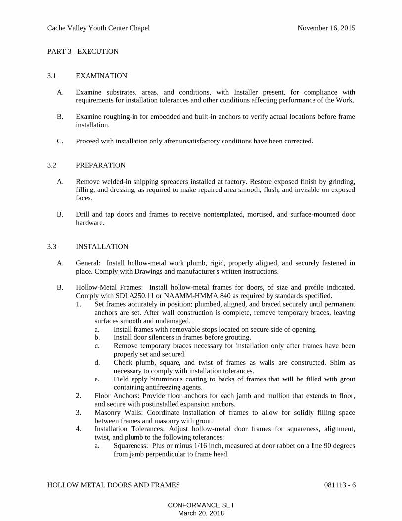
Cache Valley Youth Center Chapel November 16, 2015
HOLLOW METAL DOORS AND FRAMES 081113 - 6
PART 3 - EXECUTION
3.1 EXAMINATION
A. Examine substrates, areas, and conditions, with Installer present, for compliance with
requirements for installation tolerances and other conditions affecting performance of the Work.
B. Examine roughing-in for embedded and built-in anchors to verify actual locations before frame
installation.
C. Proceed with installation only after unsatisfactory conditions have been corrected.
3.2 PREPARATION
A. Remove welded-in shipping spreaders installed at factory. Restore exposed finish by grinding,
filling, and dressing, as required to make repaired area smooth, flush, and invisible on exposed
faces.
B. Drill and tap doors and frames to receive nontemplated, mortised, and surface-mounted door
hardware.
3.3 INSTALLATION
A. General: Install hollow-metal work plumb, rigid, properly aligned, and securely fastened in
place. Comply with Drawings and manufacturer's written instructions.
B. Hollow-Metal Frames: Install hollow-metal frames for doors, of size and profile indicated.
Comply with SDI A250.11 or NAAMM-HMMA 840 as required by standards specified.
1. Set frames accurately in position; plumbed, aligned, and braced securely until permanent
anchors are set. After wall construction is complete, remove temporary braces, leaving
surfaces smooth and undamaged.
a. Install frames with removable stops located on secure side of opening.
b. Install door silencers in frames before grouting.
c. Remove temporary braces necessary for installation only after frames have been
properly set and secured.
d. Check plumb, square, and twist of frames as walls are constructed. Shim as
necessary to comply with installation tolerances.
e. Field apply bituminous coating to backs of frames that will be filled with grout
containing antifreezing agents.
2. Floor Anchors: Provide floor anchors for each jamb and mullion that extends to floor,
and secure with postinstalled expansion anchors.
3. Masonry Walls: Coordinate installation of frames to allow for solidly filling space
between frames and masonry with grout.
4. Installation Tolerances: Adjust hollow-metal door frames for squareness, alignment,
twist, and plumb to the following tolerances:
a. Squareness: Plus or minus 1/16 inch, measured at door rabbet on a line 90 degrees
from jamb perpendicular to frame head.
CONFORMANCE SETMarch 20, 2018

Cache Valley Youth Center Chapel November 16, 2015
HOLLOW METAL DOORS AND FRAMES 081113 - 7
b. Alignment: Plus or minus 1/16 inch, measured at jambs on a horizontal line
parallel to plane of wall.
c. Twist: Plus or minus 1/16 inch, measured at opposite face corners of jambs on
parallel lines, and perpendicular to plane of wall.
d. Plumbness: Plus or minus 1/16 inch, measured at jambs at floor.
C. Hollow-Metal Doors: Fit hollow-metal doors accurately in frames, within clearances specified
below. Shim as necessary.
1. Non-Fire-Rated Steel Doors:
a. Between Door and Frame Jambs and Head: 1/8 inch plus or minus 1/32 inch.
b. At Bottom of Door: 3/4 inch plus or minus 1/32 inch.
c. Between Door Face and Stop: 1/16 inch to 1/8 inch plus or minus 1/32 inch.
D. Glazing: Comply with hollow-metal manufacturer's written instructions.
1. Secure stops with countersunk flat- or oval-head machine screws spaced uniformly not
more than 9 inches on center and not more than 2 inches from each corner.
3.4 ADJUSTING AND CLEANING
A. Final Adjustments: Check and readjust operating hardware items immediately before final
inspection. Leave work in complete and proper operating condition. Remove and replace
defective work, including hollow-metal work that is warped, bowed, or otherwise unacceptable.
B. Remove grout and other bonding material from hollow-metal work immediately after
installation.
C. Prime-Coat Touchup: Immediately after erection, sand smooth rusted or damaged areas of
prime coat and apply touchup of compatible air-drying, rust-inhibitive primer.
D. Metallic-Coated Surface Touchup: Clean abraded areas and repair with galvanizing repair paint
according to manufacturer's written instructions.
END OF SECTION 081113
CONFORMANCE SETMarch 20, 2018

Cache Valley Youth Center Chapel November 16, 2015
HOLLOW METAL DOORS AND FRAMES 081113 - 8
THIS PAGE INTENTIONALLY LEFT BLANK
CONFORMANCE SETMarch 20, 2018

Cache Valley Youth Center Chapel November 16, 2015
DOOR HARDWARE 087100 - 1
SECTION 087100 - DOOR HARDWARE
PART 1 - GENERAL
1.1 RELATED DOCUMENTS
A. Drawings and general provisions of the Contract, including General and Supplementary
Conditions and Division 01 Specification Sections, apply to this Section.
1.2 SUMMARY
A. Section Includes:
1. Mechanical door hardware for the following:
a. Swinging doors.
1.3 COORDINATION
A. Installation Templates: Distribute for doors, frames, and other work specified to be factory
prepared. Check Shop Drawings of other work to confirm that adequate provisions are made
for locating and installing door hardware to comply with indicated requirements.
B. Security: Coordinate installation of door hardware, keying, and access control with Owner's
security consultant.
1.4 ACTION SUBMITTALS
A. Product Data: For each type of product.
1. Include construction details, material descriptions, dimensions of individual components
and profiles, and finishes.
B. Door Hardware Schedule: Prepared by or under the supervision of Installer's Architectural
Hardware Consultant. Coordinate door hardware schedule with doors, frames, and related work
to ensure proper size, thickness, hand, function, and finish of door hardware.
1. Submittal Sequence: Submit door hardware schedule concurrent with submissions of
Product Data, Samples, and Shop Drawings. Coordinate submission of door hardware
schedule with scheduling requirements of other work to facilitate the fabrication of other
work that is critical in Project construction schedule.
2. Format: Use same scheduling sequence and format as in door hardware schedule in the
Contract Documents.
3. Content: Include the following information:
a. Identification number, location, hand, fire rating, size, and material of each door
and frame.
b. Locations of each door hardware set, cross-referenced to Drawings on floor plans
and to door and frame schedule.
c. Complete designations, including name and manufacturer, type, style, function,
size, quantity, function, and finish of each door hardware product.
CONFORMANCE SETMarch 20, 2018
Cache Valley Youth Center Chapel November 16, 2015
DOOR HARDWARE 087100 - 2
d. Fastenings and other installation information.
e. Explanation of abbreviations, symbols, and designations contained in door
hardware schedule.
f. Mounting locations for door hardware.
g. List of related door devices specified in other Sections for each door and frame.
1.5 INFORMATIONAL SUBMITTALS
A. Product Test Reports: For compliance with accessibility requirements, for tests performed by
manufacturer and witnessed by a qualified testing agency, for door hardware on doors located in
accessible routes.
B. Sample Warranty: For special warranty.
1.6 CLOSEOUT SUBMITTALS
A. Maintenance Data: For each type of door hardware to include in maintenance manuals.
B. Schedules: Final door hardware and keying schedule.
1.7 QUALITY ASSURANCE
A. Installer Qualifications: Supplier of products and an employer of workers trained and approved
by product manufacturers and of an Architectural Hardware Consultant who is available during
the course of the Work to consult Contractor, Architect, and Owner about door hardware and
keying.
1. Scheduling Responsibility: Preparation of door hardware and keying schedule.
B. Architectural Hardware Consultant Qualifications: A person who is experienced in providing
consulting services for door hardware installations that are comparable in material, design, and
extent to that indicated for this Project and who is currently certified by DHI as an Architectural
Hardware Consultant (AHC).
1.8 DELIVERY, STORAGE, AND HANDLING
A. Inventory door hardware on receipt and provide secure lock-up for door hardware delivered to
Project site.
B. Tag each item or package separately with identification coordinated with the final door
hardware schedule, and include installation instructions, templates, and necessary fasteners with
each item or package.
C. Deliver keys and permanent cores to Owner by personal delivery.
CONFORMANCE SETMarch 20, 2018

Cache Valley Youth Center Chapel November 16, 2015
DOOR HARDWARE 087100 - 3
1.9 WARRANTY
A. Special Warranty: Manufacturer agrees to repair or replace components of door hardware that
fail in materials or workmanship within specified warranty period.
1. Failures include, but are not limited to, the following:
a. Structural failures including excessive deflection, cracking, or breakage.
b. Faulty operation of doors and door hardware.
c. Deterioration of metals, metal finishes, and other materials beyond normal
weathering and use.
2. Warranty Period: Three years from date of Substantial Completion unless otherwise
indicated below:
a. Manual Closers: 10 years from date of Substantial Completion.
PART 2 - PRODUCTS
2.1 MANUFACTURERS
A. Source Limitations: Obtain each type of door hardware from single manufacturer.
2.2 PERFORMANCE REQUIREMENTS
A. Means of Egress Doors: Latches do not require more than 15 lbf to release the latch. Locks do
not require use of a key, tool, or special knowledge for operation.
B. Accessibility Requirements: For door hardware on doors in an accessible route, comply with
ICC A117.1.
1. Provide operating devices that do not require tight grasping, pinching, or twisting of the
wrist and that operate with a force of not more than 5 lbf.
2. Bevel raised thresholds with a slope of not more than 1:2. Provide thresholds not more
than 1/2 inch high.
3. Adjust door closer sweep periods so that, from an open position of 90 degrees, the door
will take at least 5 seconds to move to a position of 12 degrees from the latch.
2.3 SCHEDULED DOOR HARDWARE
A. Provide products for each door that comply with requirements indicated in Part 2 and door
hardware schedule.
1. Door hardware is scheduled in Part 3.
2.4 HINGES
A. Hinges: BHMA A156.1.
1. Five knuckle, plain bearing.
2. Non-removable pin (NRP).
CONFORMANCE SETMarch 20, 2018
Cache Valley Youth Center Chapel November 16, 2015
DOOR HARDWARE 087100 - 4
2.5 MECHANICAL LOCKS AND LATCHES
A. Lock Functions: As indicated in door hardware schedule.
B. Lock Throw: Comply with testing requirements for length of bolts required for labeled fire
doors, and as follows:
1. Mortise Locks: Minimum 3/4-inch latchbolt throw.
2. Deadbolts: Minimum 1-inch bolt throw.
C. Lock Backset: 2-3/4 inches unless otherwise indicated.
D. Lock Trim:
1. Levers: Forged or cast.
2. Escutcheons (Roses): Wrought.
E. Strikes: Provide manufacturer's standard strike for each lock bolt or latchbolt complying with
requirements indicated for applicable lock or latch and with strike box and curved lip extended
to protect frame; finished to match lock or latch.
F. Mortise Locks: BHMA A156.13; Security Grade 1; stamped steel case with steel or brass parts;
Series 1000.
1. Schlage L9000 Series.
2. No substitutions.
2.6 LOCK CYLINDERS
A. Lock Cylinders: Tumbler type, constructed from brass or bronze, stainless steel, or nickel silver.
B. Standard Lock Cylinders: BHMA A156.5; Grade 1 permanent cores; face finished to match
lockset.
1. Core Type: Interchangeable.
2.7 KEYING
1. Existing System:
a. Master key or grand master key locks to Owner's existing system.
B. Keys: Nickel silver.
1. Stamping: Permanently inscribe each key with a visual key control number and include
the following notation:
a. Notation: "DO NOT DUPLICATE."
2.8 MANUAL FLUSH BOLTS
A. Manual Flush Bolts: BHMA A156.16; minimum 3/4-inch throw; designed for mortising into
door edge.
CONFORMANCE SETMarch 20, 2018
Cache Valley Youth Center Chapel November 16, 2015
DOOR HARDWARE 087100 - 5
2.9 CONCEALED CLOSERS
A. Concealed Closers: BHMA A156.4; rack-and-pinion hydraulic type with adjustable sweep and
latch speeds controlled by key-operated valves. Comply with manufacturer's written instructions
for size of door closers depending on size of door, exposure to weather, and anticipated
frequency of use. Provide factory-sized closers, adjustable to meet field conditions and
requirements for opening force.
2.10 MECHANICAL STOPS AND HOLDERS
A. Wall- and Floor-Mounted Stops: BHMA A156.16.
1. As specified by Department of Juvenile Justice Services.
2.11 DOOR GASKETING
A. Door Gasketing: BHMA A156.22; with resilient or flexible seal strips that are easily
replaceable and readily available from stocks maintained by manufacturer.
B. Maximum Air Leakage: When tested according to ASTM E283 with tested pressure differential
of 0.3-inch wg, as follows:
1. Gasketing on Double Doors: 0.50 cfm per foot of door opening.
2.12 THRESHOLDS
A. Thresholds: BHMA A156.21; fabricated to full width of opening indicated.
2.13 EXIT DEVICES AND AUXILIARY ITEMS
A. Exit Devices and Auxiliary Items: BHMA A156.3, Grade 1.
2.14 FABRICATION
A. Base Metals: Produce door hardware units of base metal indicated, fabricated by forming
method indicated, using manufacturer's standard metal alloy, composition, temper, and
hardness. Furnish metals of a quality equal to or greater than that of specified door hardware
units and BHMA A156.18.
B. Fasteners: Provide door hardware manufactured to comply with published templates prepared
for machine, wood, and sheet metal screws. Provide screws that comply with commercially
recognized industry standards for application intended, except aluminum fasteners are not
permitted. Provide Phillips flat-head screws with finished heads to match surface of door
hardware unless otherwise indicated.
1. Concealed Fasteners: For door hardware units that are exposed when door is closed,
except for units already specified with concealed fasteners. Do not use through bolts for
installation where bolt head or nut on opposite face is exposed unless it is the only means
of securely attaching the door hardware. Where through bolts are used on hollow door
and frame construction, provide sleeves for each through bolt.
CONFORMANCE SETMarch 20, 2018
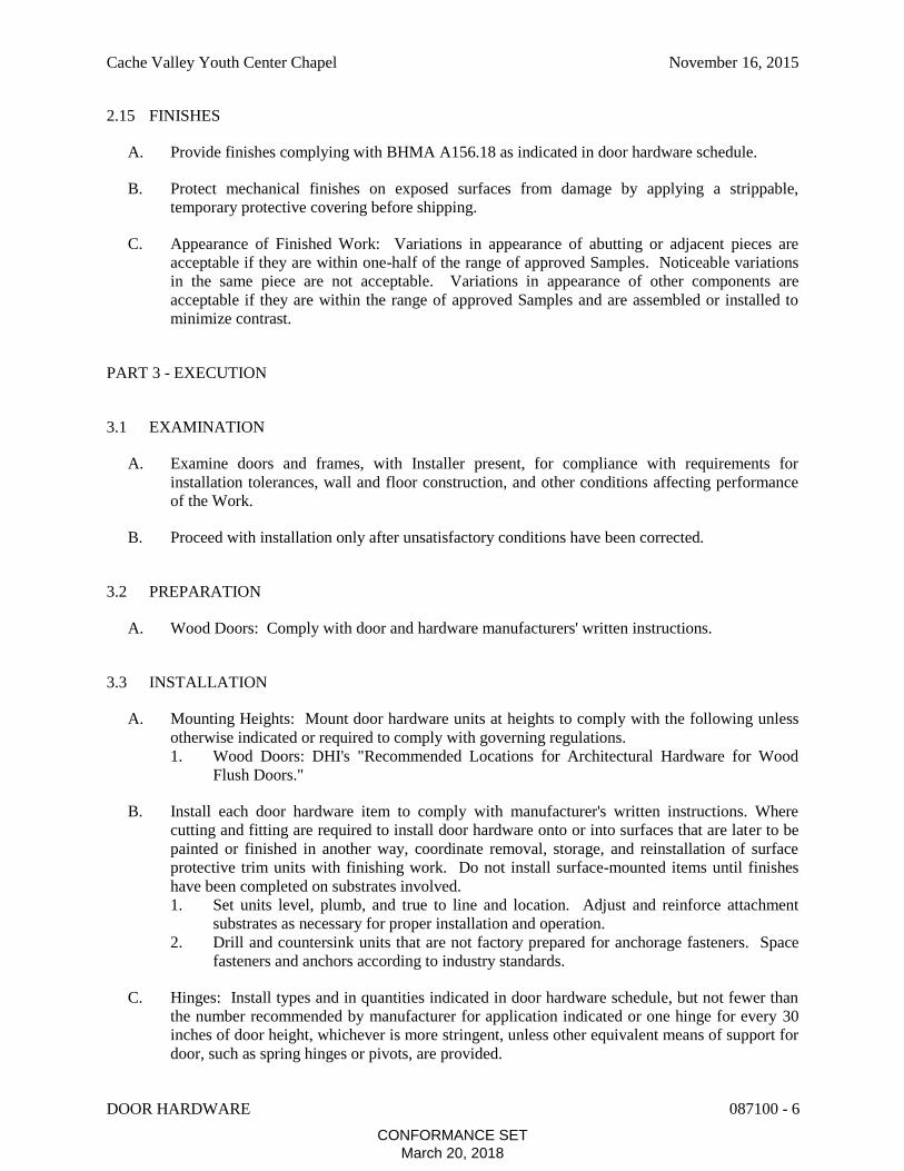
Cache Valley Youth Center Chapel November 16, 2015
DOOR HARDWARE 087100 - 6
2.15 FINISHES
A. Provide finishes complying with BHMA A156.18 as indicated in door hardware schedule.
B. Protect mechanical finishes on exposed surfaces from damage by applying a strippable,
temporary protective covering before shipping.
C. Appearance of Finished Work: Variations in appearance of abutting or adjacent pieces are
acceptable if they are within one-half of the range of approved Samples. Noticeable variations
in the same piece are not acceptable. Variations in appearance of other components are
acceptable if they are within the range of approved Samples and are assembled or installed to
minimize contrast.
PART 3 - EXECUTION
3.1 EXAMINATION
A. Examine doors and frames, with Installer present, for compliance with requirements for
installation tolerances, wall and floor construction, and other conditions affecting performance
of the Work.
B. Proceed with installation only after unsatisfactory conditions have been corrected.
3.2 PREPARATION
A. Wood Doors: Comply with door and hardware manufacturers' written instructions.
3.3 INSTALLATION
A. Mounting Heights: Mount door hardware units at heights to comply with the following unless
otherwise indicated or required to comply with governing regulations.
1. Wood Doors: DHI's "Recommended Locations for Architectural Hardware for Wood
Flush Doors."
B. Install each door hardware item to comply with manufacturer's written instructions. Where
cutting and fitting are required to install door hardware onto or into surfaces that are later to be
painted or finished in another way, coordinate removal, storage, and reinstallation of surface
protective trim units with finishing work. Do not install surface-mounted items until finishes
have been completed on substrates involved.
1. Set units level, plumb, and true to line and location. Adjust and reinforce attachment
substrates as necessary for proper installation and operation.
2. Drill and countersink units that are not factory prepared for anchorage fasteners. Space
fasteners and anchors according to industry standards.
C. Hinges: Install types and in quantities indicated in door hardware schedule, but not fewer than
the number recommended by manufacturer for application indicated or one hinge for every 30
inches of door height, whichever is more stringent, unless other equivalent means of support for
door, such as spring hinges or pivots, are provided.
CONFORMANCE SETMarch 20, 2018
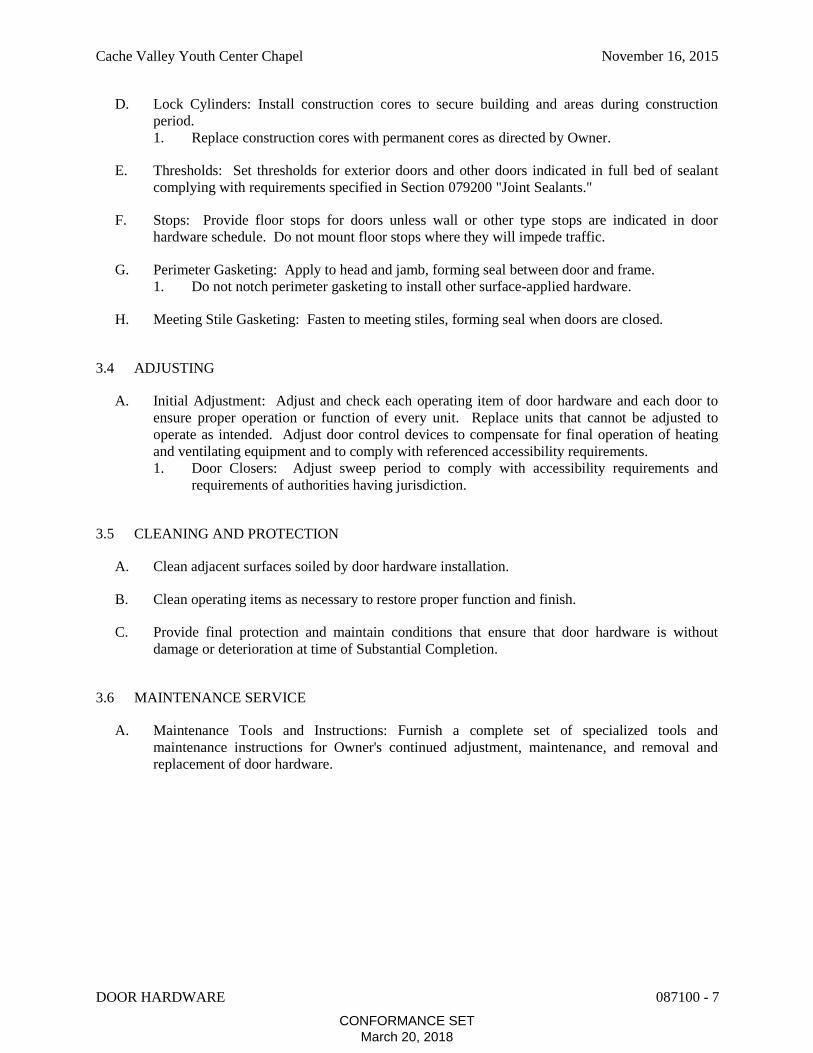
Cache Valley Youth Center Chapel November 16, 2015
DOOR HARDWARE 087100 - 7
D. Lock Cylinders: Install construction cores to secure building and areas during construction
period.
1. Replace construction cores with permanent cores as directed by Owner.
E. Thresholds: Set thresholds for exterior doors and other doors indicated in full bed of sealant
complying with requirements specified in Section 079200 "Joint Sealants."
F. Stops: Provide floor stops for doors unless wall or other type stops are indicated in door
hardware schedule. Do not mount floor stops where they will impede traffic.
G. Perimeter Gasketing: Apply to head and jamb, forming seal between door and frame.
1. Do not notch perimeter gasketing to install other surface-applied hardware.
H. Meeting Stile Gasketing: Fasten to meeting stiles, forming seal when doors are closed.
3.4 ADJUSTING
A. Initial Adjustment: Adjust and check each operating item of door hardware and each door to
ensure proper operation or function of every unit. Replace units that cannot be adjusted to
operate as intended. Adjust door control devices to compensate for final operation of heating
and ventilating equipment and to comply with referenced accessibility requirements.
1. Door Closers: Adjust sweep period to comply with accessibility requirements and
requirements of authorities having jurisdiction.
3.5 CLEANING AND PROTECTION
A. Clean adjacent surfaces soiled by door hardware installation.
B. Clean operating items as necessary to restore proper function and finish.
C. Provide final protection and maintain conditions that ensure that door hardware is without
damage or deterioration at time of Substantial Completion.
3.6 MAINTENANCE SERVICE
A. Maintenance Tools and Instructions: Furnish a complete set of specialized tools and
maintenance instructions for Owner's continued adjustment, maintenance, and removal and
replacement of door hardware.
CONFORMANCE SETMarch 20, 2018
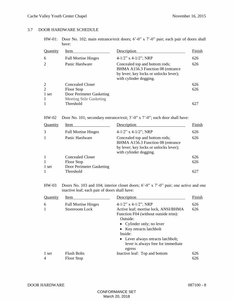
Cache Valley Youth Center Chapel November 16, 2015
DOOR HARDWARE 087100 - 8
3.7 DOOR HARDWARE SCHEDULE
HW-01: Door No. 102; main entrance/exit doors; 6’-0” x 7’-0” pair; each pair of doors shall
have:
Quantity Item Description Finish
6 Full Mortise Hinges 4-1/2” x 4-1/2”; NRP 626
2 Panic Hardware Concealed top and bottom rods; 626
BHMA A156.3 Function 08 (entrance
by lever; key locks or unlocks lever);
with cylinder dogging.
2 Concealed Closer 626
2 Floor Stop 626
1 set Door Perimeter Gasketing
1 Meeting Stile Gasketing
1 Threshold 627
HW-02 Door No. 101; secondary entrance/exit; 3’-0” x 7’-0”; each door shall have:
Quantity Item Description Finish
3 Full Mortise Hinges 4-1/2” x 4-1/2”; NRP 626
1 Panic Hardware Concealed top and bottom rods; 626
BHMA A156.3 Function 08 (entrance
by lever; key locks or unlocks lever);
with cylinder dogging.
1 Concealed Closer 626
1 Floor Stop 626
1 set Door Perimeter Gasketing
1 Threshold 627
HW-03 Doors No. 103 and 104; interior closet doors; 6’-0” x 7’-0” pair; one active and one
inactive leaf; each pair of doors shall have:
Quantity Item Description Finish
6 Full Mortise Hinges 4-1/2” x 4-1/2”; NRP 626
1 Storeroom Lock Active leaf; mortise lock, ANSI/BHMA 626
Function F04 (without outside trim):
Outside:
Cylinder only; no lever
Key retracts latchbolt
Inside:
Lever always retracts latchbolt;
lever is always free for immediate
egress
1 set Flush Bolts Inactive leaf: Top and bottom 626
4 Floor Stop 626
CONFORMANCE SETMarch 20, 2018

Cache Valley Youth Center Chapel November 16, 2015
DOOR HARDWARE 087100 - 9
HW-04 Door No. 105; interior HVAC equipment access doors; 6’-0” x 6’-5-1/2” pair; one
active and one inactive leaf; each pair of doors shall have:
Quantity Item Description Finish
6 Full Mortise Hinges 4-1/2” x 4-1/2”; NRP 626
1 Storeroom Lock Active leaf; mortise lock, ANSI/BHMA 626
Function F04 (without outside trim):
Outside:
Cylinder only; no lever
Key retracts latchbolt
Inside:
Lever always retracts latchbolt;
lever is always free for immediate
egress
1 set Flush Bolts Inactive leaf: Top and bottom 626
2 Wall Stop 626
HW-05 Door No. 100; security yard egress door; 3’-0” x 7’-0”; each door shall have:
Quantity Item Description Finish
3 Full Mortise Hinges 4-1/2” x 4-1/2”; NRP 626
1 Concealed Closer 626
Electric lockset and dual sided call box with camera as specified by
Wasatch Controls.
END OF SECTION 087100
CONFORMANCE SETMarch 20, 2018

Cache Valley Youth Center Chapel November 16, 2015
DOOR HARDWARE 087100 - 10
THIS PAGE INTENTIONALLY LEFT BLANK
CONFORMANCE SETMarch 20, 2018

Cache Valley Youth Center Chapel November 16, 2015
NON-STRUCTURAL METAL FRAMING 092216 - 1
SECTION 092216 - NON-STRUCTURAL METAL FRAMING
PART 1 - GENERAL
1.1 RELATED DOCUMENTS
A. Drawings and general provisions of the Contract, including General and Supplementary
Conditions and Division 01 Specification Sections, apply to this Section.
1.2 SUMMARY
A. Section Includes:
1. Non-load-bearing steel framing systems for interior partitions.
2. Steel framing system for interior ceiling.
3. Soffit framing.
1.3 ACTION SUBMITTALS
A. Product Data: For each type of product.
1. Studs and Runners: Provide documentation that framing members' certification is
according to SIFA's "Code Compliance Certification Program for Cold-Formed Steel
Structural and Non-Structural Framing Members."
PART 2 - PRODUCTS
2.1 PERFORMANCE REQUIREMENTS
A. Fire-Test-Response Characteristics: For fire-resistance-rated assemblies that incorporate non-
load-bearing steel framing, provide materials and construction identical to those tested in
assembly indicated, according to ASTM E119 by an independent testing agency.
2.2 FRAMING SYSTEMS
A. Framing Members, General: Comply with ASTM C754 for conditions indicated.
1. Steel Sheet Components: Comply with ASTM C645 requirements for metal unless
otherwise indicated.
2. Protective Coating: ASTM A653/A653M, G40, hot-dip galvanized unless otherwise
indicated.
B. Studs and Runners: ASTM C645.
1. Steel Studs and Runners:
a. Minimum Base-Metal Thickness: 0.0329 inch (20 gauge).
b. Depth: As indicated on Drawings.
CONFORMANCE SETMarch 20, 2018

Cache Valley Youth Center Chapel November 16, 2015
NON-STRUCTURAL METAL FRAMING 092216 - 2
C. Slip-Type Head Joints: Where indicated, provide one of the following:
1. Clip System: Clips designed for use in head-of-wall deflection conditions that provide a
positive attachment of studs to runners while allowing 2-inch minimum vertical
movement.
2. Single Long-Leg Runner System: ASTM C645 top runner with 2-inch- deep flanges in
thickness not less than indicated for studs, installed with studs friction fit into top runner
and with continuous bridging located within 12 inches of the top of studs to provide
lateral bracing.
3. Double-Runner System: ASTM C645 top runners, inside runner with 2-inch- deep
flanges in thickness not less than indicated for studs and fastened to studs, and outer
runner sized to friction fit inside runner.
4. Deflection Track: Steel sheet top runner manufactured to prevent cracking of finishes
applied to interior partition framing resulting from deflection of structure above; in
thickness not less than indicated for studs and in width to accommodate depth of studs.
D. Hat-Shaped, Rigid Furring Channels: ASTM C645.
1. Minimum Base-Metal Thickness: 0.0329 inch (20 gauge).
2. Depth: 7/8 inch.
E. Flat Strap and Backing Plate: Steel sheet for blocking and bracing in length and width
indicated.
1. Minimum Base-Metal Thickness: 0.0329 inch.
F. Tie Wire: ASTM A641/A641M, Class 1 zinc coating, soft temper, 0.062-inch- diameter wire,
or double strand of 0.048-inch- diameter wire.
2.3 AUXILIARY MATERIALS
A. General: Provide auxiliary materials that comply with referenced installation standards.
1. Fasteners for Metal Framing: Of type, material, size, corrosion resistance, holding
power, and other properties required to fasten steel members to substrates.
PART 3 - EXECUTION
3.1 EXAMINATION
A. Examine areas and substrates, with Installer present, and including welded hollow-metal frames,
cast-in anchors, and structural framing, for compliance with requirements and other conditions
affecting performance of the Work.
B. Proceed with installation only after unsatisfactory conditions have been corrected.
CONFORMANCE SETMarch 20, 2018

Cache Valley Youth Center Chapel November 16, 2015
NON-STRUCTURAL METAL FRAMING 092216 - 3
3.2 PREPARATION
A. Coordination with Sprayed Fire-Resistive Materials:
1. Before sprayed fire-resistive materials are applied, attach offset anchor plates or ceiling
runners (tracks) to surfaces indicated to receive sprayed fire-resistive materials. Where
offset anchor plates are required, provide continuous plates fastened to building structure
not more than 24 inches on center.
2. After sprayed fire-resistive materials are applied, remove them only to extent necessary
for installation of non-load-bearing steel framing. Do not reduce thickness of fire-
resistive materials below that are required for fire-resistance ratings indicated. Protect
adjacent fire-resistive materials from damage.
3.3 INSTALLATION, GENERAL
A. Installation Standard: ASTM C754.
1. Gypsum Board Assemblies: Also comply with requirements in ASTM C840 that apply
to framing installation.
B. Install framing and accessories plumb, square, and true to line, with connections securely
fastened.
C. Install supplementary framing, and blocking to support fixtures, equipment services, heavy trim,
grab bars, toilet accessories, furnishings, or similar construction.
D. Install bracing at terminations in assemblies.
3.4 INSTALLING FRAMED ASSEMBLIES
A. Install framing system components according to spacings indicated, but not greater than
spacings required by referenced installation standards for assembly types.
1. Single-Layer Application: 16 inches on center unless otherwise indicated.
2. Multilayer Application: 16 inches on center unless otherwise indicated.
B. Where studs are installed directly against exterior masonry walls or dissimilar metals at exterior
walls, install isolation strip between studs and exterior wall.
C. Install studs so flanges within framing system point in same direction.
D. Install tracks (runners) at floors and overhead supports. Extend framing full height to structural
supports or substrates above suspended ceilings except where partitions are indicated to
terminate at suspended ceilings. Continue framing around ducts that penetrate partitions above
ceiling.
1. Slip-Type Head Joints: Where framing extends to overhead structural supports, install to
produce joints at tops of framing systems that prevent axial loading of finished
assemblies.
2. Door Openings: Screw vertical studs at jambs to jamb anchor clips on door frames;
install runner track section (for cripple studs) at head and secure to jamb studs.
a. Install two studs at each jamb unless otherwise indicated.
CONFORMANCE SETMarch 20, 2018
Cache Valley Youth Center Chapel November 16, 2015
NON-STRUCTURAL METAL FRAMING 092216 - 4
b. Extend jamb studs through suspended ceilings and attach to underside of overhead
structure.
E. Installation Tolerance: Install each framing member so fastening surfaces vary not more than
1/8 inch from the plane formed by faces of adjacent framing.
END OF SECTION 092216
CONFORMANCE SETMarch 20, 2018
Cache Valley Youth Center Chapel November 16, 2015
GYPSUM BOARD 092900 - 1
SECTION 092900 - GYPSUM BOARD
PART 1 - GENERAL
1.1 RELATED DOCUMENTS
A. Drawings and general provisions of the Contract, including General and Supplementary
Conditions and Division 01 Specification Sections, apply to this Section.
1.2 SUMMARY
A. Section Includes:
1. Interior gypsum board.
B. Related Requirements:
1. Section 092216 "Non-Structural Metal Framing" for non-structural steel framing and
suspension systems that support gypsum board panels.
1.3 ACTION SUBMITTALS
A. Product Data: For each type of product.
1.4 DELIVERY, STORAGE AND HANDLING
A. Store materials inside under cover and keep them dry and protected against weather,
condensation, direct sunlight, construction traffic, and other potential causes of damage. Stack
panels flat and supported on risers on a flat platform to prevent sagging.
1.5 FIELD CONDITIONS
A. Environmental Limitations: Comply with ASTM C840 requirements or gypsum board
manufacturer's written instructions, whichever are more stringent.
B. Do not install paper-faced gypsum panels until installation areas are enclosed and conditioned.
C. Do not install panels that are wet, moisture damaged, and mold damaged.
1. Indications that panels are wet or moisture damaged include, but are not limited to,
discoloration, sagging, or irregular shape.
2. Indications that panels are mold damaged include, but are not limited to, fuzzy or
splotchy surface contamination and discoloration.
CONFORMANCE SETMarch 20, 2018

Cache Valley Youth Center Chapel November 16, 2015
GYPSUM BOARD 092900 - 2
PART 2 - PRODUCTS
2.1 PERFORMANCE REQUIREMENTS
A. Fire-Resistance-Rated Assemblies: For fire-resistance-rated assemblies, provide materials and
construction identical to those tested in assembly indicated according to ASTM E119 by an
independent testing agency.
2.2 GYPSUM BOARD, GENERAL
A. Size: Provide maximum lengths and widths available that will minimize joints in each area and
that correspond with support system indicated.
2.3 INTERIOR GYPSUM BOARD
A. Gypsum Board, Type X: ASTM C1396/C 1396M.
1. Thickness: 5/8 inch.
2. Long Edges: Tapered.
B. Flexible Gypsum Board: ASTM C1396/C1396M. Manufactured to bend to fit radii and to be
more flexible than standard regular-type gypsum board of same thickness.
1. Thickness: 1/4 inch.
2. Long Edges: Tapered.
2.4 TRIM ACCESSORIES
A. Interior Trim: ASTM C1047.
1. Material: Galvanized or aluminum-coated steel sheet or rolled zinc.
2. Shapes:
a. Cornerbead.
b. LC-Bead: J-shaped; exposed long flange receives joint compound.
B. Aluminum Trim: Extruded accessories of profiles and dimensions indicated.
1. Basis-of-Design: Fry Reglet Reveal Molding No. DRM-50-50; reveal width 1/2 inch.
2. Aluminum: Alloy and temper with not less than the strength and durability properties of
ASTM B221, Alloy 6063-T5.
3. Finish: Corrosion-resistant primer compatible with joint compound and finish materials
specified.
2.5 JOINT TREATMENT MATERIALS
A. General: Comply with ASTM C475/C475M.
B. Joint Tape:
1. Interior Gypsum Board: Paper.
CONFORMANCE SETMarch 20, 2018
Cache Valley Youth Center Chapel November 16, 2015
GYPSUM BOARD 092900 - 3
C. Joint Compound for Interior Gypsum Board: For each coat, use formulation that is compatible
with other compounds applied on previous or for successive coats.
1. Prefilling: At open joints and damaged surface areas, use setting-type taping compound.
2. Embedding and First Coat: For embedding tape and first coat on joints, fasteners, and
trim flanges, use setting-type taping compound.
3. Fill Coat: For second coat, use drying-type, all-purpose compound.
4. Finish Coat: For third coat, use drying-type, all-purpose compound.
2.6 AUXILIARY MATERIALS
A. General: Provide auxiliary materials that comply with referenced installation standards and
manufacturer's written instructions.
B. Laminating Adhesive: Adhesive or joint compound recommended for directly adhering
gypsum panels to continuous substrate.
C. Steel Drill Screws: ASTM C1002 unless otherwise indicated.
PART 3 - EXECUTION
3.1 EXAMINATION
A. Examine areas and substrates, with Installer present, for compliance with requirements and
other conditions affecting performance of the Work.
B. Examine panels before installation. Reject panels that are wet, moisture damaged, and mold
damaged.
C. Proceed with installation only after unsatisfactory conditions have been corrected.
3.2 APPLYING AND FINISHING PANELS, GENERAL
A. Comply with ASTM C840.
B. Install ceiling panels across framing to minimize the number of abutting end joints and to avoid
abutting end joints in central area of each ceiling. Stagger abutting end joints of adjacent panels
not less than one framing member.
C. Install panels with face side out. Butt panels together for a light contact at edges and ends with
not more than 1/16 inch of open space between panels. Do not force into place.
D. Locate edge and end joints over supports, except in ceiling applications where intermediate
supports or gypsum board back-blocking is provided behind end joints. Do not place tapered
edges against cut edges or ends. Stagger vertical joints on opposite sides of partitions. Do not
make joints other than control joints at corners of framed openings.
E. Form control and expansion joints with space between edges of adjoining gypsum panels.
CONFORMANCE SETMarch 20, 2018

Cache Valley Youth Center Chapel November 16, 2015
GYPSUM BOARD 092900 - 4
F. Cover both faces of support framing with gypsum panels in concealed spaces (above ceilings,
etc.), except in chases braced internally.
1. Unless concealed application is indicated or required for sound, fire, air, or smoke
ratings, coverage may be accomplished with scraps of not less than 8 square feet in area.
2. Fit gypsum panels around ducts, pipes, and conduits.
G. Isolate perimeter of gypsum board applied to non-load-bearing partitions at structural
abutments. Provide 1/4- to 1/2-inch- wide spaces at these locations and trim edges with edge
trim where edges of panels are exposed. Seal joints between edges and abutting structural
surfaces with acoustical sealant.
H. Attachment to Steel Framing: Attach panels so leading edge or end of each panel is attached to
open (unsupported) edges of stud flanges first.
3.3 APPLYING INTERIOR GYPSUM BOARD
A. Install interior gypsum board in the following locations:
1. Type X: Vertical surfaces unless otherwise indicated.
2. Flexible Type: Apply in double layer at ceiling.
B. Single-Layer Application:
1. On ceilings, apply gypsum panels before wall/partition board application to greatest
extent possible and at right angles to framing unless otherwise indicated.
2. On partitions/walls, apply gypsum panels vertically (parallel to framing) unless otherwise
indicated or required by fire-resistance-rated assembly, and minimize end joints.
a. Stagger abutting end joints not less than one framing member in alternate courses
of panels.
3. Fastening Methods: Apply gypsum panels to supports with steel drill screws.
C. Multilayer Application:
1. On ceilings, apply gypsum board indicated for base layers before applying base layers on
walls/partitions; apply face layers in same sequence. Apply base layers at right angles to
framing members and offset face-layer joints one framing member, 16 inches minimum,
from parallel base-layer joints, unless otherwise indicated or required by fire-resistance-
rated assembly.
2. Fastening Methods: Fasten base layers and face layers separately to supports with
screws.
D. Curved Surfaces:
1. Install panels horizontally (perpendicular to supports) and unbroken, to extent possible,
across curved surface plus 12-inch- long straight sections at ends of curves and tangent to
them.
2. For double-layer construction, fasten base layer to studs with screws 16 inches on center
Center gypsum board face layer over joints in base layer, and fasten to studs with screws
spaced 12 inches on center.
CONFORMANCE SETMarch 20, 2018

Cache Valley Youth Center Chapel November 16, 2015
GYPSUM BOARD 092900 - 5
3.4 INSTALLING TRIM ACCESSORIES
A. General: For trim with back flanges intended for fasteners, attach to framing with same
fasteners used for panels. Otherwise, attach trim according to manufacturer's written
instructions.
B. Interior Trim: Install in the following locations:
1. Cornerbead: Use at outside corners unless otherwise indicated.
2. LC-Bead: Use at exposed panel edges.
C. Aluminum Trim: Install in locations indicated on Drawings.
3.5 FINISHING GYPSUM BOARD
A. General: Treat gypsum board joints, interior angles, edge trim, control joints, penetrations,
fastener heads, surface defects, and elsewhere as required to prepare gypsum board surfaces for
decoration. Promptly remove residual joint compound from adjacent surfaces.
B. Prefill open joints and damaged surface areas.
C. Apply joint tape over gypsum board joints, except for trim products specifically indicated as not
intended to receive tape.
D. Gypsum Board Finish Levels: Finish panels to levels indicated below and according to
ASTM C840:
1. Level 4: At panel surfaces that will be exposed to view unless otherwise indicated.
a. Primer and its application to surfaces are specified in Section 099123 "Interior
Painting."
3.6 PROTECTION
A. Protect adjacent surfaces from drywall compound and promptly remove from floors and other
non-drywall surfaces. Repair surfaces stained, marred, or otherwise damaged during drywall
application.
B. Protect installed products from damage from weather, condensation, direct sunlight,
construction, and other causes during remainder of the construction period.
C. Remove and replace panels that are wet, moisture damaged, and mold damaged.
1. Indications that panels are wet or moisture damaged include, but are not limited to,
discoloration, sagging, or irregular shape.
2. Indications that panels are mold damaged include, but are not limited to, fuzzy or
splotchy surface contamination and discoloration.
END OF SECTION 092900
CONFORMANCE SETMarch 20, 2018
Cache Valley Youth Center Chapel November 16, 2015
GYPSUM BOARD 092900 - 6
THIS PAGE INTENTIONALLY LEFT BLANK
CONFORMANCE SETMarch 20, 2018
Cache Valley Youth Center Chapel November 16, 2015
EXTERIOR PAINTING 099113 - 1
SECTION 099113 - EXTERIOR PAINTING
PART 1 - GENERAL
1.1 RELATED DOCUMENTS
A. Drawings and general provisions of the Contract, including General and Supplementary
Conditions and Division 01 Specification Sections, apply to this Section.
1.2 SUMMARY
A. Section includes surface preparation and the application of paint systems on exterior substrates.
B. Related Requirements:
1. Section 051200 "Structural Steel Framing" for shop priming of metal substrates.
1.3 DEFINITIONS
A. MPI Gloss Level 5: 35 to 70 units at 60 degrees, according to ASTM D523.
1.4 ACTION SUBMITTALS
A. Product Data: For each type of product. Include preparation requirements and application
instructions.
1. Include printout of current "MPI Approved Products List" for each product category
specified, with the proposed product highlighted.
2. Indicate VOC content.
B. Samples for Initial Selection: For each type of topcoat product.
C. Samples for Verification: For each type of paint system and each color and gloss of topcoat.
1. Submit Samples on rigid backing, 8 inches square.
2. Apply coats on Samples in steps to show each coat required for system.
3. Label each coat of each Sample.
4. Label each Sample for location and application area.
D. Product List: Cross-reference to paint system and locations of application areas. Use same
designations indicated on Drawings and in schedules. Include color designations.
1.5 MAINTENANCE MATERIAL SUBMITTALS
A. Furnish extra materials that match products installed and that are packaged with protective
covering for storage and identified with labels describing contents.
1. Paint: 5 percent, but not less than 1 gallon of each material and color applied.
CONFORMANCE SETMarch 20, 2018

Cache Valley Youth Center Chapel November 16, 2015
EXTERIOR PAINTING 099113 - 2
1.6 DELIVERY, STORAGE, AND HANDLING
A. Store materials not in use in tightly covered containers in well-ventilated areas with ambient
temperatures continuously maintained at not less than 45 degrees F.
1. Maintain containers in clean condition, free of foreign materials and residue.
2. Remove rags and waste from storage areas daily.
1.7 FIELD CONDITIONS
A. Apply paints only when temperature of surfaces to be painted and ambient air temperatures are
between 50 and 95 degrees F.
B. Do not apply paints in snow, rain, fog, or mist; when relative humidity exceeds 85 percent; at
temperatures less than 5 degrees F above the dew point; or to damp or wet surfaces.
PART 2 - PRODUCTS
2.1 MANUFACTURERS
A. Products: Subject to compliance with requirements, provide products listed in the Exterior
Painting Schedule for the paint category indicated.
2.2 PAINT, GENERAL
A. MPI Standards: Products shall comply with MPI standards indicated and shall be listed in its
"MPI Approved Products Lists."
B. Material Compatibility:
1. Materials for use within each paint system shall be compatible with one another and
substrates indicated, under conditions of service and application as demonstrated by
manufacturer, based on testing and field experience.
2. For each coat in a paint system, products shall be recommended in writing by topcoat
manufacturers for use in paint system and on substrate indicated.
C. Colors: As selected by Architect from manufacturer's full range.
2.3 SOURCE QUALITY CONTROL
A. Testing of Paint Materials: Owner reserves the right to invoke the following procedure:
1. Owner will engage the services of a qualified testing agency to sample paint materials.
Contractor will be notified in advance and may be present when samples are taken. If
paint materials have already been delivered to Project site, samples may be taken at
Project site. Samples will be identified, sealed, and certified by testing agency.
2. Testing agency will perform tests for compliance with product requirements.
3. Owner may direct Contractor to stop applying paints if test results show materials being
used do not comply with product requirements. Contractor shall remove noncomplying
paint materials from Project site, pay for testing, and repaint surfaces painted with
CONFORMANCE SETMarch 20, 2018
Cache Valley Youth Center Chapel November 16, 2015
EXTERIOR PAINTING 099113 - 3
rejected materials. Contractor will be required to remove rejected materials from
previously painted surfaces if, on repainting with complying materials, the two paints are
incompatible.
PART 3 - EXECUTION
3.1 EXAMINATION
A. Examine substrates and conditions, with Applicator present, for compliance with requirements
for maximum moisture content and other conditions affecting performance of the Work.
B. Verify suitability of substrates, including surface conditions and compatibility, with existing
finishes and primers.
C. Proceed with coating application only after unsatisfactory conditions have been corrected.
1. Application of coating indicates acceptance of surfaces and conditions.
3.2 PREPARATION
A. Comply with manufacturer's written instructions and recommendations in "MPI Architectural
Painting Specification Manual" applicable to substrates and paint systems indicated.
B. Remove hardware, covers, plates, and similar items already in place that are removable and are
not to be painted. If removal is impractical or impossible because of size or weight of item,
provide surface-applied protection before surface preparation and painting.
1. After completing painting operations, use workers skilled in the trades involved to
reinstall items that were removed. Remove surface-applied protection.
C. Clean substrates of substances that could impair bond of paints, including dust, dirt, oil, grease,
and incompatible paints and encapsulants.
1. Remove incompatible primers and reprime substrate with compatible primers or apply tie
coat as required to produce paint systems indicated.
D. Steel Substrates: Remove rust, loose mill scale, and shop primer if any. Clean using methods
recommended in writing by paint manufacturer.
E. Shop-Primed Steel Substrates: Clean field welds, bolted connections, and areas where shop
paint is abraded. Paint exposed areas with the same material as used for shop priming to comply
with SSPC-PA 1 for touching up shop-primed surfaces.
F. Galvanized-Metal Substrates: Remove grease and oil residue from galvanized sheet metal by
mechanical methods to produce clean, lightly etched surfaces that promote adhesion of
subsequently applied paints.
CONFORMANCE SETMarch 20, 2018

Cache Valley Youth Center Chapel November 16, 2015
EXTERIOR PAINTING 099113 - 4
3.3 APPLICATION
A. Apply paints according to manufacturer's written instructions and recommendations in "MPI
Architectural Painting Specification Manual."
1. Use applicators and techniques suited for paint and substrate indicated.
2. Paint surfaces behind movable items same as similar exposed surfaces. Before final
installation, paint surfaces behind permanently fixed items with prime coat only.
3. Paint both sides and edges of exterior doors and entire exposed surface of exterior door
frames.
4. Do not paint over labels of independent testing agencies or equipment name,
identification, performance rating, or nomenclature plates.
5. Primers specified in painting schedules may be omitted on items that are factory primed
or factory finished if acceptable to topcoat manufacturers.
B. If undercoats or other conditions show through topcoat, apply additional coats until cured film
has a uniform paint finish, color, and appearance.
C. Apply paints to produce surface films without cloudiness, spotting, holidays, laps, brush marks,
roller tracking, runs, sags, ropiness, or other surface imperfections. Cut in sharp lines and color
breaks.
3.4 FIELD QUALITY CONTROL
A. Dry Film Thickness Testing: Owner may engage the services of a qualified testing and
inspecting agency to inspect and test paint for dry film thickness.
1. Contractor shall touch up and restore painted surfaces damaged by testing.
2. If test results show that dry film thickness of applied paint does not comply with paint
manufacturer's written recommendations, Contractor shall pay for testing and apply
additional coats as needed to provide dry film thickness that complies with paint
manufacturer's written recommendations.
3.5 CLEANING AND PROTECTION
A. At end of each workday, remove rubbish, empty cans, rags, and other discarded materials from
Project site.
B. After completing paint application, clean spattered surfaces. Remove spattered paints by
washing, scraping, or other methods. Do not scratch or damage adjacent finished surfaces.
C. Protect work of other trades against damage from paint application. Correct damage to work of
other trades by cleaning, repairing, replacing, and refinishing, as approved by Architect, and
leave in an undamaged condition.
D. At completion of construction activities of other trades, touch up and restore damaged or
defaced painted surfaces.
CONFORMANCE SETMarch 20, 2018
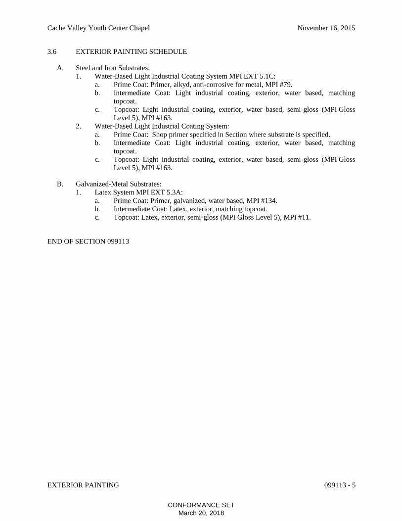
Cache Valley Youth Center Chapel November 16, 2015
EXTERIOR PAINTING 099113 - 5
3.6 EXTERIOR PAINTING SCHEDULE
A. Steel and Iron Substrates:
1. Water-Based Light Industrial Coating System MPI EXT 5.1C:
a. Prime Coat: Primer, alkyd, anti-corrosive for metal, MPI #79.
b. Intermediate Coat: Light industrial coating, exterior, water based, matching
topcoat.
c. Topcoat: Light industrial coating, exterior, water based, semi-gloss (MPI Gloss
Level 5), MPI #163.
2. Water-Based Light Industrial Coating System:
a. Prime Coat: Shop primer specified in Section where substrate is specified.
b. Intermediate Coat: Light industrial coating, exterior, water based, matching
topcoat.
c. Topcoat: Light industrial coating, exterior, water based, semi-gloss (MPI Gloss
Level 5), MPI #163.
B. Galvanized-Metal Substrates:
1. Latex System MPI EXT 5.3A:
a. Prime Coat: Primer, galvanized, water based, MPI #134.
b. Intermediate Coat: Latex, exterior, matching topcoat.
c. Topcoat: Latex, exterior, semi-gloss (MPI Gloss Level 5), MPI #11.
END OF SECTION 099113
CONFORMANCE SETMarch 20, 2018

Cache Valley Youth Center Chapel November 16, 2015
EXTERIOR PAINTING 099113 - 6
BLANK PAGE
CONFORMANCE SETMarch 20, 2018
Cache Valley Youth Center Chapel November 16, 2015
INTERIOR PAINTING 099123 - 1
SECTION 099123 - INTERIOR PAINTING
PART 1 - GENERAL
1.1 RELATED DOCUMENTS
A. Drawings and general provisions of the Contract, including General and Supplementary
Conditions and Division 01 Specification Sections, apply to this Section.
1.2 SUMMARY
A. Section includes surface preparation and the application of paint systems on the following
interior substrates:
1. Gypsum board.
2. Steel and iron.
1.3 DEFINITIONS
A. MPI Gloss Level 1: Not more than five units at 60 degrees and 10 units at 85 degrees, according
to ASTM D523.
B. MPI Gloss Level 5: 35 to 70 units at 60 degrees, according to ASTM D523.
1.4 ACTION SUBMITTALS
A. Product Data: For each type of product. Include preparation requirements and application
instructions.
1. Include Printout of current "MPI Approved Products List" for each product category
specified, with the proposed product highlighted.
2. Indicate VOC content.
B. Samples for Verification: For each type of paint system and in each color and gloss of topcoat.
1. Submit Samples on rigid backing, 8 inches square.
2. Apply coats on Samples in steps to show each coat required for system.
3. Label each coat of each Sample.
4. Label each Sample for location and application area.
C. Product List: Cross-reference to paint system and locations of application areas. Use same
designations indicated on Drawings and in schedules. Include color designations.
CONFORMANCE SETMarch 20, 2018

Cache Valley Youth Center Chapel November 16, 2015
INTERIOR PAINTING 099123 - 2
1.5 DELIVERY, STORAGE, AND HANDLING
A. Store materials not in use in tightly covered containers in well-ventilated areas with ambient
temperatures continuously maintained at not less than 45 degrees F.
1. Maintain containers in clean condition, free of foreign materials and residue.
2. Remove rags and waste from storage areas daily.
1.6 FIELD CONDITIONS
A. Apply paints only when temperature of surfaces to be painted and ambient air temperatures are
between 50 and 95 degrees F.
B. Do not apply paints when relative humidity exceeds 85 percent; at temperatures less than 5
degrees F above the dew point; or to damp or wet surfaces.
PART 2 - PRODUCTS
2.1 PAINT, GENERAL
A. MPI Standards: Products shall comply with MPI standards indicated and shall be listed in its
"MPI Approved Products Lists."
B. Material Compatibility:
1. Materials for use within each paint system shall be compatible with one another and
substrates indicated, under conditions of service and application as demonstrated by
manufacturer, based on testing and field experience.
2. For each coat in a paint system, products shall be recommended in writing by topcoat
manufacturers for use in paint system and on substrate indicated.
C. Colors: As selected by Architect from manufacturer's full range.
PART 3 - EXECUTION
3.1 EXAMINATION
A. Examine substrates and conditions, with Applicator present, for compliance with requirements
for maximum moisture content and other conditions affecting performance of the Work.
B. Maximum Moisture Content of Substrates: When measured with an electronic moisture meter
as follows:
1. Gypsum Board: 12 percent.
C. Gypsum Board Substrates: Verify that finishing compound is sanded smooth.
D. Proceed with coating application only after unsatisfactory conditions have been corrected.
1. Application of coating indicates acceptance of surfaces and conditions.
CONFORMANCE SETMarch 20, 2018

Cache Valley Youth Center Chapel November 16, 2015
INTERIOR PAINTING 099123 - 3
3.2 PREPARATION
A. Comply with manufacturer's written instructions and recommendations in "MPI Architectural
Painting Specification Manual" applicable to substrates and paint systems indicated.
B. Remove hardware, covers, plates, and similar items already in place that are removable and are
not to be painted. If removal is impractical or impossible because of size or weight of item,
provide surface-applied protection before surface preparation and painting.
1. After completing painting operations, use workers skilled in the trades involved to
reinstall items that were removed. Remove surface-applied protection if any.
C. Clean substrates of substances that could impair bond of paints, including dust, dirt, oil, grease,
and incompatible paints and encapsulants.
1. Remove incompatible primers and reprime substrate with compatible primers or apply tie
coat as required to produce paint systems indicated.
D. Shop-Primed Steel Substrates: Clean field welds, bolted connections, and areas where shop
paint is abraded. Paint exposed areas with the same material as used for shop priming to comply
with SSPC-PA 1 for touching up shop-primed surfaces.
3.3 APPLICATION
A. Apply paints according to manufacturer's written instructions and to recommendations in "MPI
Manual."
1. Use applicators and techniques suited for paint and substrate indicated.
2. Paint surfaces behind movable equipment and furniture same as similar exposed surfaces.
Before final installation, paint surfaces behind permanently fixed equipment or furniture
with prime coat only.
3. Paint front and backsides of access panels, removable or hinged covers, and similar
hinged items to match exposed surfaces.
4. Do not paint over labels of independent testing agencies or equipment name,
identification, performance rating, or nomenclature plates.
5. Primers specified in painting schedules may be omitted on items that are factory primed
or factory finished if acceptable to topcoat manufacturers.
B. Tint each undercoat a lighter shade to facilitate identification of each coat if multiple coats of
same material are to be applied. Tint undercoats to match color of topcoat, but provide
sufficient difference in shade of undercoats to distinguish each separate coat.
C. If undercoats or other conditions show through topcoat, apply additional coats until cured film
has a uniform paint finish, color, and appearance.
D. Apply paints to produce surface films without cloudiness, spotting, holidays, laps, brush marks,
roller tracking, runs, sags, ropiness, or other surface imperfections. Cut in sharp lines and color
breaks.
E. Paint portions of internal surfaces of metal ducts, without liner, behind air inlets and outlets that
are visible from occupied spaces.
CONFORMANCE SETMarch 20, 2018

Cache Valley Youth Center Chapel November 16, 2015
INTERIOR PAINTING 099123 - 4
3.4 CLEANING AND PROTECTION
A. At end of each workday, remove rubbish, empty cans, rags, and other discarded materials from
Project site.
B. After completing paint application, clean spattered surfaces. Remove spattered paints by
washing, scraping, or other methods. Do not scratch or damage adjacent finished surfaces.
C. Protect work of other trades against damage from paint application. Correct damage to work of
other trades by cleaning, repairing, replacing, and refinishing, as approved by Architect, and
leave in an undamaged condition.
D. At completion of construction activities of other trades, touch up and restore damaged or
defaced painted surfaces.
3.5 INTERIOR PAINTING SCHEDULE
A. Gypsum Board Substrates:
1. Latex over Latex Sealer System MPI INT 9.2A:
a. Prime Coat: Primer sealer, latex, interior, MPI #50.
b. Intermediate Coat: Latex, interior, matching topcoat.
c. Topcoat: Latex, interior, flat (MPI Gloss Level 1), MPI #53.
B. Steel Substrates:
1. Latex System, Shop Primer:
a. Prime Coat: Shop primer specified in Section where substrate is specified.
b. Intermediate Coat: Latex, interior, matching topcoat.
c. Topcoat: Latex, interior, semi-gloss (MPI Gloss Level 5), MPI #54.
END OF SECTION 099123
CONFORMANCE SETMarch 20, 2018

Cache Valley Youth Center Chapel November 16, 2015
CONCRETE PAVING 321313 - 1
SECTION 321313 - CONCRETE PAVING
PART 1 - GENERAL
1.1 RELATED DOCUMENTS
A. Drawings and general provisions of the Contract, including General and Supplementary
Conditions and Division 01 Specification Sections, apply to this Section.
1.2 SUMMARY
A. Section Includes Concrete Paving.
B. Related Requirements:
1. Section 033000 "Cast-in-Place Concrete for general building applications of concrete.
1.3 DEFINITIONS
A. Cementitious Materials: Portland cement alone or in combination with one or more of blended
hydraulic cement, fly ash, slag cement, and other pozzolans.
B. W/C Ratio: The ratio by weight of water to cementitious materials.
1.4 ACTION SUBMITTALS
A. Product Data: For each type of product.
B. Design Mixtures: For each concrete paving mixture. Include alternate design mixtures when
characteristics of materials, Project conditions, weather, test results, or other circumstances
warrant adjustments.
1.5 QUALITY ASSURANCE
A. Ready-Mix-Concrete Manufacturer Qualifications: A firm experienced in manufacturing ready-
mixed concrete products and that complies with ASTM C 94/C 94M requirements for
production facilities and equipment.
1.6 FIELD CONDITIONS
A. Traffic Control: Maintain access for vehicular and pedestrian traffic as required for other
construction activities.
CONFORMANCE SETMarch 20, 2018

Cache Valley Youth Center Chapel November 16, 2015
CONCRETE PAVING 321313 - 2
B. Cold-Weather Concrete Placement: Protect concrete work from physical damage or reduced
strength that could be caused by frost, freezing, or low temperatures. Comply with ACI 306.1
and the following:
1. When air temperature has fallen to or is expected to fall below 40 degrees F, uniformly
heat water and aggregates before mixing to obtain a concrete mixture temperature of not
less than 50 degrees F and not more than 80 degrees F at point of placement.
2. Do not use frozen materials or materials containing ice or snow.
3. Do not use calcium chloride, salt, or other materials containing antifreeze agents or
chemical accelerators unless otherwise specified and approved in design mixtures.
C. Hot-Weather Concrete Placement: Comply with ACI 301 and as follows when hot-weather
conditions exist:
1. Cool ingredients before mixing to maintain concrete temperature below 90 degrees F at
time of placement. Chilled mixing water or chopped ice may be used to control
temperature, provided water equivalent of ice is calculated in total amount of mixing
water. Using liquid nitrogen to cool concrete is Contractor's option.
2. Cover steel reinforcement with water-soaked burlap, so steel temperature will not exceed
ambient air temperature immediately before embedding in concrete.
3. Fog-spray forms, steel reinforcement, and subgrade just before placing concrete. Keep
subgrade moisture uniform without standing water, soft spots, or dry areas.
PART 2 - PRODUCTS
2.1 CONCRETE, GENERAL
A. ACI Publications: Comply with ACI 301 unless otherwise indicated.
2.2 FORMS
A. Form Materials: Plywood, metal, metal-framed plywood, or other approved panel-type
materials to provide full-depth, continuous, straight, and smooth exposed surfaces.
1. Use flexible or uniformly curved forms for curves with a radius of 100 feet or less.
B. Form-Release Agent: Commercially formulated form-release agent that will not bond with,
stain, or adversely affect concrete surfaces and that will not impair subsequent treatments of
concrete surfaces.
2.3 STEEL REINFORCEMENT
A. Plain-Steel Welded-Wire Reinforcement: ASTM A 1064/A 1064M, fabricated from as-drawn
steel wire into flat sheets.
B. Plain-Steel Wire: ASTM A 1064/A 1064M, as drawn.
C. Bar Supports: Bolsters, chairs, spacers, and other devices for spacing, supporting, and fastening
reinforcing bars, welded-wire reinforcement, and dowels in place. Manufacture bar supports
CONFORMANCE SETMarch 20, 2018

Cache Valley Youth Center Chapel November 16, 2015
CONCRETE PAVING 321313 - 3
according to CRSI's "Manual of Standard Practice" from steel wire, plastic, or precast concrete
of greater compressive strength than concrete specified, and as follows:
1. Equip wire bar supports with sand plates or horizontal runners where base material will
not support chair legs.
2.4 CONCRETE MATERIALS
A. Cementitious Materials: Use the following cementitious materials, of same type, brand, and
source throughout Project:
1. Portland Cement: ASTM C150/C150M, gray portland cement Type I.
2. Fly Ash: ASTM C618, Class C or Class F.
3. Slag Cement: ASTM C989/C989M, Grade 100 or 120.
B. Normal-Weight Aggregates: ASTM C33/C33M, Class 4S, uniformly graded. Provide
aggregates from a single.
1. Maximum Coarse-Aggregate Size: 3/4 inch nominal.
2. Fine Aggregate: Free of materials with deleterious reactivity to alkali in cement.
C. Air-Entraining Admixture: ASTM C260/C260M.
D. Water: Potable and complying with ASTM C94/C94M.
2.5 CURING MATERIALS
A. Absorptive Cover: AASHTO M 182, Class 3, burlap cloth made from jute or kenaf, weighing
approximately 9 ounces/square yard dry, or cotton mats.
B. Moisture-Retaining Cover: ASTM C 171, polyethylene film or white burlap-polyethylene
sheet.
C. Water: Potable.
D. Evaporation Retarder: Waterborne, monomolecular, film forming, manufactured for application
to fresh concrete.
2.6 RELATED MATERIALS
A. Joint Fillers: ASTMD 1751, asphalt-saturated cellulosic fiber or ASTM D1752, cork or self-
expanding cork in preformed strips.
B. Bonding Agent: ASTM C1059/C 1059M, Type II, non-redispersible, acrylic emulsion or
styrene butadiene.
CONFORMANCE SETMarch 20, 2018

Cache Valley Youth Center Chapel November 16, 2015
CONCRETE PAVING 321313 - 4
2.7 CONCRETE MIXTURES
A. Prepare design mixtures, proportioned according to ACI 301, for each type and strength of
normal-weight concrete, and as determined by either laboratory trial mixtures or field
experience.
1. Use a qualified independent testing agency for preparing and reporting proposed concrete
design mixtures for the trial batch method.
B. Cementitious Materials: Limit percentage, by weight, of cementitious materials other than
portland cement in concrete as follows:
1. Fly Ash or Pozzolan: 25 percent.
2. Slag Cement: 50 percent.
3. Combined Fly Ash or Pozzolan, and Slag Cement: 50 percent, with fly ash or pozzolan
not exceeding 25 percent.
C. Add air-entraining admixture at manufacturer's prescribed rate to result in normal-weight
concrete at point of placement having an air content as follows:
1. Air Content: 6 percent plus or minus 1-1/2 percent for 3/4-inch nominal maximum
aggregate size.
D. Limit water-soluble, chloride-ion content in hardened concrete to 0.15 percent by weight of
cement.
E. Concrete Mixtures: Normal-weight concrete.
1. Compressive Strength (28 Days): 3500 psi.
2. Maximum W/C Ratio at Point of Placement: 0.45.
3. Slump Limit: 4 inches, plus or minus 1 inch.
F. Ready-Mixed Concrete: Measure, batch, and mix concrete materials and concrete according to
ASTM C94/C94M. Furnish batch certificates for each batch discharged and used in the Work.
1. When air temperature is between 85 and 90 degrees F, reduce mixing and delivery time
from 1-1/2 hours to 75 minutes; when air temperature is above 90 degrees F, reduce
mixing and delivery time to 60 minutes.
G. Project-Site Mixing: Measure, batch, and mix concrete materials and concrete according to
ASTM C94/C94M. Mix concrete materials in appropriate drum-type batch machine mixer.
1. For concrete batches of 1 cubic yard or smaller, continue mixing at least 1-1/2 minutes,
but not more than 5 minutes after ingredients are in mixer, before any part of batch is
released.
2. For concrete batches larger than 1 cubic yard, increase mixing time by 15 seconds for
each additional 1 cubic yard.
3. Provide batch ticket for each batch discharged and used in the Work, indicating Project
identification name and number, date, mixture type, mixing time, quantity, and amount of
water added.
CONFORMANCE SETMarch 20, 2018
Cache Valley Youth Center Chapel November 16, 2015
CONCRETE PAVING 321313 - 5
PART 3 - EXECUTION
3.1 EXAMINATION
A. Examine exposed subgrades and subbase surfaces for compliance with requirements for
dimensional, grading, and elevation tolerances.
B. Proceed with installation only after unsatisfactory conditions have been corrected.
3.2 PREPARATION
A. Remove loose material from compacted subbase surface immediately before placing concrete.
3.3 EDGE FORMS AND SCREED CONSTRUCTION
A. Set, brace, and secure edge forms, bulkheads, and intermediate screed guides to required lines,
grades, and elevations. Install forms to allow continuous progress of work and so forms can
remain in place at least 24 hours after concrete placement.
B. Clean forms after each use and coat with form-release agent to ensure separation from concrete
without damage.
3.4 STEEL REINFORCEMENT INSTALLATION
A. General: Comply with CRSI's "Manual of Standard Practice" for fabricating, placing, and
supporting reinforcement.
B. Clean reinforcement of loose rust and mill scale, earth, ice, or other bond-reducing materials.
C. Arrange, space, and securely tie bars and bar supports to hold reinforcement in position during
concrete placement. Maintain minimum cover to reinforcement.
D. Install welded-wire reinforcement in lengths as long as practicable. Lap adjoining pieces at least
one full mesh, and lace splices with wire. Offset laps of adjoining widths to prevent continuous
laps in either direction.
3.5 JOINTS
A. General: Form construction, isolation, and contraction joints and tool edges true to line, with
faces perpendicular to surface plane of concrete. Construct transverse joints at right angles to
centerline unless otherwise indicated.
1. When joining existing paving, place transverse joints to align with previously placed
joints unless otherwise indicated.
CONFORMANCE SETMarch 20, 2018

Cache Valley Youth Center Chapel November 16, 2015
CONCRETE PAVING 321313 - 6
B. Construction Joints: Set construction joints at side and end terminations of paving and at
locations where paving operations are stopped for more than one-half hour unless paving
terminates at isolation joints.
1. Continue steel reinforcement across construction joints unless otherwise indicated. Do
not continue reinforcement through sides of paving strips unless otherwise indicated.
2. Butt Joints: Use bonding agent at joint locations where fresh concrete is placed against
hardened or partially hardened concrete surfaces.
C. Isolation Joints: Form isolation joints of preformed joint-filler strips abutting concrete curbs,
catch basins, manholes, inlets, structures, other fixed objects, and where indicated.
1. Locate expansion joints at intervals of 50 feet unless otherwise indicated.
2. Extend joint fillers full width and depth of joint.
3. Terminate joint filler not less than 1/2 inch or more than 1 inch below finished surface if
joint sealant is indicated.
4. Place top of joint filler flush with finished concrete surface if joint sealant is not
indicated.
5. Furnish joint fillers in one-piece lengths. Where more than one length is required, lace or
clip joint-filler sections together.
6. During concrete placement, protect top edge of joint filler with metal, plastic, or other
temporary preformed cap. Remove protective cap after concrete has been placed on both
sides of joint.
D. Contraction Joints: Form weakened-plane contraction joints, sectioning concrete into areas as
indicated. Construct contraction joints for a depth equal to at least one-fourth of the concrete
thickness, as follows:
1. Grooved Joints: Form contraction joints after initial floating by grooving and finishing
each edge of joint with grooving tool to a 3/8-inch radius. Repeat grooving of contraction
joints after applying surface finishes. Eliminate grooving-tool marks on concrete
surfaces.
2. Sawed Joints: Form contraction joints with power saws equipped with shatterproof
abrasive or diamond-rimmed blades. Cut 1/8-inch-wide joints into concrete when cutting
action will not tear, abrade, or otherwise damage surface and before developing random
contraction cracks.
E. Edging: After initial floating, tool edges of paving, gutters, curbs, and joints in concrete with an
edging tool to a 3/8-inch radius. Repeat tooling of edges after applying surface finishes.
Eliminate edging-tool marks on concrete surfaces.
3.6 CONCRETE PLACEMENT
A. Before placing concrete, inspect and complete formwork installation, steel reinforcement, and
items to be embedded or cast-in.
B. Remove snow, ice, or frost from subbase surface and steel reinforcement before placing
concrete. Do not place concrete on frozen surfaces.
C. Moisten subbase to provide a uniform dampened condition at time concrete is placed. Do not
place concrete around manholes or other structures until they are at required finish elevation and
alignment.
CONFORMANCE SETMarch 20, 2018

Cache Valley Youth Center Chapel November 16, 2015
CONCRETE PAVING 321313 - 7
D. Comply with ACI 301 requirements for measuring, mixing, transporting, and placing concrete.
E. Do not add water to concrete during delivery or at Project site. Do not add water to fresh
concrete after testing.
F. Deposit and spread concrete in a continuous operation between transverse joints. Do not push
or drag concrete into place or use vibrators to move concrete into place.
G. Consolidate concrete according to ACI 301 by mechanical vibrating equipment supplemented
by hand spading, rodding, or tamping.
1. Consolidate concrete along face of forms and adjacent to transverse joints with an
internal vibrator. Keep vibrator away from joint assemblies, reinforcement, or side forms.
Use only square-faced shovels for hand spreading and consolidation. Consolidate with
care to prevent dislocating reinforcement, and joint devices.
H. Screed paving surface with a straightedge and strike off.
I. Commence initial floating using bull floats or darbies to impart an open-textured and uniform
surface plane before excess moisture or bleedwater appears on the surface. Do not further
disturb concrete surfaces before beginning finishing operations or spreading surface treatments.
3.7 FLOAT FINISHING
A. General: Do not add water to concrete surfaces during finishing operations.
B. Float Finish: Begin the second floating operation when bleedwater sheen has disappeared and
concrete surface has stiffened sufficiently to permit operations. Float surface with power-driven
floats or by hand floating if area is small or inaccessible to power units. Finish surfaces to true
planes. Cut down high spots and fill low spots. Refloat surface immediately to uniform granular
texture.
1. Medium-to-Fine-Textured Broom Finish: Draw a soft-bristle broom across float-finished
concrete surface, perpendicular to line of traffic, to provide a uniform, fine-line texture.
3.8 CONCRETE PROTECTION AND CURING
A. General: Protect freshly placed concrete from premature drying and excessive cold or hot
temperatures.
B. Comply with ACI 306.1 for cold-weather protection.
C. Evaporation Retarder: Apply evaporation retarder to concrete surfaces if hot, dry, or windy
conditions cause moisture loss approaching 0.2 lb/sq. ft. x h before and during finishing
operations. Apply according to manufacturer's written instructions after placing, screeding, and
bull floating or darbying concrete but before float finishing.
D. Begin curing after finishing concrete but not before free water has disappeared from concrete
surface.
CONFORMANCE SETMarch 20, 2018

Cache Valley Youth Center Chapel November 16, 2015
CONCRETE PAVING 321313 - 8
E. Curing Methods: Cure concrete by moisture curing as follows:
1. Moisture Curing: Keep surfaces continuously moist for not less than seven days with the
following materials:
a. Water.
b. Continuous water-fog spray.
c. Absorptive cover, water saturated and kept continuously wet. Cover concrete
surfaces and edges with 12-inch lap over adjacent absorptive covers.
3.9 PAVING TOLERANCES
A. Comply with tolerances in ACI 117 and as follows:
1. Elevation: 3/4 inch.
2. Thickness: Plus 3/8 inch, minus 1/4 inch.
3. Surface: Gap below 10-feet-long; unleveled straightedge not to exceed 1/2 inch.
4. Joint Spacing: 3 inches.
5. Contraction Joint Depth: Plus 1/4 inch, no minus.
6. Joint Width: Plus 1/8 inch, no minus.
3.10 FIELD QUALITY CONTROL
A. Testing Agency: Owner will engage a qualified testing agency to perform tests and inspections.
B. Testing Services: Testing and inspecting of composite samples of fresh concrete obtained
according to ASTM C172/C172M shall be performed according to the following requirements:
1. Testing Frequency: Obtain at least one composite sample for each 100 cubic yards or
fraction thereof of each concrete mixture placed each day.
a. When frequency of testing will provide fewer than five compressive-strength tests
for each concrete mixture, testing shall be conducted from at least five randomly
selected batches or from each batch if fewer than five are used.
2. Slump: ASTM C143/C143M; one test at point of placement for each composite sample,
but not less than one test for each day's pour of each concrete mixture. Perform additional
tests when concrete consistency appears to change.
3. Air Content: ASTM C231/C231M, pressure method; one test for each composite sample,
but not less than one test for each day's pour of each concrete mixture.
4. Concrete Temperature: ASTM C1064/C1064M; one test hourly when air temperature is
40 degrees F and below and when it is 80 degrees F and above, and one test for each
composite sample.
5. Compression Test Specimens: ASTM C31/C31M; cast and laboratory cure one set of
three standard cylinder specimens for each composite sample.
6. Compressive-Strength Tests: ASTM C39/C39M; test one specimen at seven days and
two specimens at 28 days.
a. A compressive-strength test shall be the average compressive strength from two
specimens obtained from same composite sample and tested at 28 days.
C. Strength of each concrete mixture will be satisfactory if average of any three consecutive
compressive-strength tests equals or exceeds specified compressive strength and no
compressive-strength test value falls below specified compressive strength by more than 500
psi.
CONFORMANCE SETMarch 20, 2018

Cache Valley Youth Center Chapel November 16, 2015
CONCRETE PAVING 321313 - 9
D. Test results shall be reported in writing to Architect, concrete manufacturer, and Contractor
within 48 hours of testing. Reports of compressive-strength tests shall contain Project
identification name and number, date of concrete placement, name of concrete testing and
inspecting agency, location of concrete batch in Work, design compressive strength at 28 days,
concrete mixture proportions and materials, compressive breaking strength, and type of break
for both 7- and 28-day tests.
E. Nondestructive Testing: Impact hammer, sonoscope, or other nondestructive device may be
permitted by Architect but will not be used as sole basis for approval or rejection of concrete.
F. Additional Tests: Testing and inspecting agency shall make additional tests of concrete when
test results indicate that slump, air entrainment, compressive strengths, or other requirements
have not been met, as directed by Architect.
G. Concrete paving will be considered defective if it does not pass tests and inspections.
H. Additional testing and inspecting, at Contractor's expense, will be performed to determine
compliance of replaced or additional work with specified requirements.
I. Prepare test and inspection reports.
3.11 REPAIR AND PROTECTION
A. Remove and replace concrete paving that is broken, damaged, or defective or that does not
comply with requirements in this Section. Remove work in complete sections from joint to joint
unless otherwise approved by Architect.
B. Drill test cores, where directed by Architect, when necessary to determine magnitude of cracks
or defective areas. Fill drilled core holes in satisfactory paving areas with portland cement
concrete bonded to paving with epoxy adhesive.
C. Protect concrete paving from damage. Exclude traffic from paving for at least 14 days after
placement. When construction traffic is permitted, maintain paving as clean as possible by
removing surface stains and spillage of materials as they occur.
D. Maintain concrete paving free of stains, discoloration, dirt, and other foreign material. Sweep
paving not more than two days before date scheduled for Substantial Completion inspections.
END OF SECTION 321313
CONFORMANCE SETMarch 20, 2018

Cache Valley Youth Center Chapel November 16, 2015
CONCRETE PAVING 321313 - 10
THIS PAGE INTENTIONALLY LEFT BLANK
CONFORMANCE SETMarch 20, 2018

ENERGY
COMPLIANCE
DOCUMENTATION
CONFORMANCE SETMarch 20, 2018

THIS PAGE INTENTIONALLY LEFT BLANK
CONFORMANCE SETMarch 20, 2018
COMcheck Software Version 4.0.2.3
Envelope Compliance Certificate
Project Title:
2012 IECC
Project Type: AdditionVertical Glazing / Wall Area: 16%
Location: Logan, UtahClimate Zone: 6b
Construction Site:Cache Valley Youth Center2051 North 600 WestLogan, UT 84321
Owner/Agent:Department of Juvenile JusticeServices
Designer/Contractor:Cartwright-AEC595 S Riverwoods ParkwaySuite 270Logan, UT 84321435.752.2850
Project Information
Energy Code:
Interfaith Youth Chapel
Building Area Floor Area
1-Religious building : Nonresidential 800
Envelope Assemblies
Assembly CavityR-Value
Cont.R-Value
ProposedU-Factor
Budget U-Factor(a)
Gross Areaor
Perimeter
Roof 1: Metal Building, Standing Seam, Single Insulation Layer withThermal Blocks (c), [Bldg. Use 1 - Religious building]
800 0.0 16.2 0.059 0.031
Exterior Wall 1: Concrete Block:12", Solid Grouted, Normal Density,Furring: None, [Bldg. Use 1 - Religious building]
1581 --- 15.0 0.058 0.078
Window 1: Metal Frame:Fixed, Perf. Type: Energy code default, SinglePane, Clear , SHGC 0.80, [Bldg. Use 1 - Religious building]
256 --- --- 1.200 0.360
Door 1: Wood, Swinging, [Bldg. Use 1 - Religious building] 76 --- --- 0.640 0.370Floor 1: Slab-On-Grade:Unheated, Horizontal with vertical >= 4 ft.,[Bldg. Use 1 - Religious building] (b)
800 --- 20.0 0.106 0.441
(a) Budget U-factors are used for software baseline calculations ONLY, and are not code requirements.(b) Slab-On-Grade proposed and budget U-factors shown in table are F-factors.(c) Thermal spacer block with minimum R-3.5 must be installed above the purlin/batt, and the roof deck secured to the purlins.
Envelope Compliance StatementCompliance Statement: The proposed envelope design represented in this document is consistent with the building plans,specifications, and other calculations submitted with this permit application. The proposed envelope systems have beendesigned to meet the 2012 IECC requirements in COMcheck Version 4.0.2.3 and to comply with the mandatory requirements
Envelope PASSES: Design 14% better than code
Project Title:Data filename:
Interfaith Youth ChapelU:\Projects\2015\115040 Cache Valley Youth Center Chapel\04 Reports\03 COMcheck EnvelopeCompliance\Interfaith Youth Chapel COMcheck 1-6-2016.cck
01/15/16Report date:91 ofPage
CONFORMANCE SETMarch 20, 2018

listed in the Inspection Checklist.
Name - Title Signature Date
Project Title:Data filename:
Interfaith Youth ChapelU:\Projects\2015\115040 Cache Valley Youth Center Chapel\04 Reports\03 COMcheck EnvelopeCompliance\Interfaith Youth Chapel COMcheck 1-6-2016.cck
01/15/16Report date:92 ofPage
Justin Campbell Architect 1/15/16
CONFORMANCE SETMarch 20, 2018
Inspection ChecklistRequirements: 0.0% were addressed directly in the COMcheck software
COMcheck Software Version 4.0.2.3
Text in the "Comments/Assumptions" column is provided by the user in the COMcheck Requirements screen. For eachrequirement, the user certifies that a code requirement will be met and how that is documented, or that an exceptionis being claimed. Where compliance is itemized in a separate table, a reference to that table is provided.
Energy Code: 2012 IECC
Section#
& Req.IDPlan Review Complies? Comments/Assumptions
C103.2[PR1]1
Plans and/or specifications provide allinformation with which compliancecan be determined for the buildingenvelope and document whereexceptions to the standard areclaimed.
CompliesDoes NotNot ObservableNot Applicable
C406[PR9]1
Plans, specifications, and/orcalculations provide all informationwith which compliance can bedetermined for the additional energyefficiency package options.
CompliesDoes NotNot ObservableNot Applicable
C402.3.1[PR10]1
The vertical fenestration area <= 30percent of the gross above-grade wallarea.
CompliesDoes NotNot ObservableNot Applicable
C402.3.1[PR11]1
The skylight area <= 3 percent of thegross roof area.
CompliesDoes NotNot ObservableNot Applicable
C402.3.2.2[PR15]1
Skylights in office, storage,automotive service, manufacturing,non-refrigerated warehouse, retailstore, and distribution/sorting areahave a measured haze value > 90percent unless designed to excludedirect sunlight.
CompliesDoes NotNot ObservableNot Applicable
Additional Comments/Assumptions:
1 High Impact (Tier 1) 2 Medium Impact (Tier 2) 3 Low Impact (Tier 3)
Project Title:Data filename:
Interfaith Youth ChapelU:\Projects\2015\115040 Cache Valley Youth Center Chapel\04 Reports\03 COMcheck EnvelopeCompliance\Interfaith Youth Chapel COMcheck 1-6-2016.cck
01/15/16Report date:93 ofPage
CONFORMANCE SETMarch 20, 2018
Section#
& Req.IDFooting / Foundation Inspection Complies? Comments/Assumptions
C402.2.6[FO3]2
Slab edge insulation R-value. CompliesDoes NotNot ObservableNot Applicable
See the Envelope Assemblies table for values.
C303.2[FO4]2
Slab edge insulation installed permanufacturer’s instructions.
CompliesDoes NotNot ObservableNot Applicable
C402.2.6[FO5]2
Slab edge insulation depth/length.Slab insulation extending away frombuilding is covered by pavement or>= 10 inches of soil.
CompliesDoes NotNot ObservableNot Applicable
See the Envelope Assemblies table for values.
C403.2.7,C408.2.8,C404.5[FO6]1
Exterior insulation protected againstdamage, sunlight, moisture, wind,landscaping and equipmentmaintenance activities.
CompliesDoes NotNot ObservableNot Applicable
C402.2.8[FO12]3
Bottom surface of floor structuresincorporating radiant heatinginsulated to >=R-3.5.
CompliesDoes NotNot ObservableNot Applicable
See the Envelope Assemblies table for values.
Additional Comments/Assumptions:
1 High Impact (Tier 1) 2 Medium Impact (Tier 2) 3 Low Impact (Tier 3)
Project Title:Data filename:
Interfaith Youth ChapelU:\Projects\2015\115040 Cache Valley Youth Center Chapel\04 Reports\03 COMcheck EnvelopeCompliance\Interfaith Youth Chapel COMcheck 1-6-2016.cck
01/15/16Report date:94 ofPage
CONFORMANCE SETMarch 20, 2018

Section#
& Req.IDFraming / Rough-In Inspection Complies? Comments/Assumptions
C402.4.1,C402.4.2[FR16]1
The building envelope contains acontinuous air barrier that is sealed inan approved manner and eitherconstructed or tested in an approvedmanner. Air barrier penetrations aresealed in an approved manner.
CompliesDoes NotNot ObservableNot Applicable
C402.4.3,C402.4.4[FR18]3
Factory-built fenestration and doorsare labeled as meeting air leakagerequirements.
CompliesDoes NotNot ObservableNot Applicable
C402.4.7[FR17]3
Vestibules are installed on all buildingentrances. Doors have self-closingdevices.
CompliesDoes NotNot ObservableNot Applicable
C402.3.3,C402.3.4[FR8]1
Vertical fenestration U-Factor. CompliesDoes NotNot ObservableNot Applicable
See the Envelope Assemblies table for values.
C402.3.3[FR10]1
Vertical fenestration SHGC value. CompliesDoes NotNot ObservableNot Applicable
See the Envelope Assemblies table for values.
C303.1.3[FR12]2
Fenestration products rated inaccordance with NFRC.
CompliesDoes NotNot ObservableNot Applicable
C303.1.3[FR13]1
Fenestration products are certified asto performance labels or certificatesprovided.
CompliesDoes NotNot ObservableNot Applicable
C402.2.7[FR14]2
U-factor of opaque doors associatedwith the building thermal envelopemeets requirements.
CompliesDoes NotNot ObservableNot Applicable
See the Envelope Assemblies table for values.
Additional Comments/Assumptions:
1 High Impact (Tier 1) 2 Medium Impact (Tier 2) 3 Low Impact (Tier 3)
Project Title:Data filename:
Interfaith Youth ChapelU:\Projects\2015\115040 Cache Valley Youth Center Chapel\04 Reports\03 COMcheck EnvelopeCompliance\Interfaith Youth Chapel COMcheck 1-6-2016.cck
01/15/16Report date:95 ofPage
CONFORMANCE SETMarch 20, 2018
Section#
& Req.IDMechanical Rough-In Inspection Complies? Comments/Assumptions
C402.4.5.1[ME3]3
Stair and elevator shaft vents havemotorized dampers that automaticallyclose.
CompliesDoes NotNot ObservableNot Applicable
C402.4.5.2[ME58]3
Outdoor air and exhaust systems havemotorized dampers that automaticallyshut when not in use and meetmaximum leakage rates. Checkgravity dampers where allowed.
CompliesDoes NotNot ObservableNot Applicable
Additional Comments/Assumptions:
1 High Impact (Tier 1) 2 Medium Impact (Tier 2) 3 Low Impact (Tier 3)
Project Title:Data filename:
Interfaith Youth ChapelU:\Projects\2015\115040 Cache Valley Youth Center Chapel\04 Reports\03 COMcheck EnvelopeCompliance\Interfaith Youth Chapel COMcheck 1-6-2016.cck
01/15/16Report date:96 ofPage
CONFORMANCE SETMarch 20, 2018
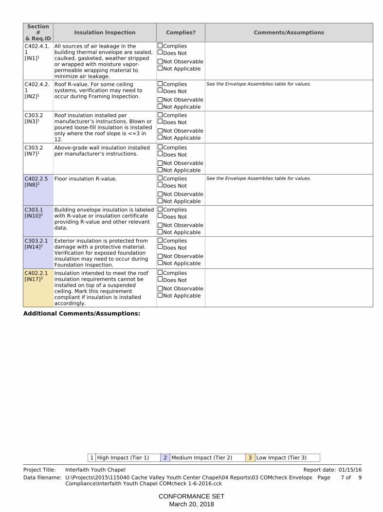
Section#
& Req.IDInsulation Inspection Complies? Comments/Assumptions
C402.4.1.1[IN1]1
All sources of air leakage in thebuilding thermal envelope are sealed,caulked, gasketed, weather strippedor wrapped with moisture vapor-permeable wrapping material tominimize air leakage.
CompliesDoes NotNot ObservableNot Applicable
C402.4.2.1[IN2]1
Roof R-value. For some ceilingsystems, verification may need tooccur during Framing Inspection.
CompliesDoes NotNot ObservableNot Applicable
See the Envelope Assemblies table for values.
C303.2[IN3]1
Roof insulation installed permanufacturer’s instructions. Blown orpoured loose-fill insulation is installedonly where the roof slope is <=3 in12.
CompliesDoes NotNot ObservableNot Applicable
C303.2[IN7]1
Above-grade wall insulation installedper manufacturer’s instructions.
CompliesDoes NotNot ObservableNot Applicable
C402.2.5[IN8]2
Floor insulation R-value. CompliesDoes NotNot ObservableNot Applicable
See the Envelope Assemblies table for values.
C303.1[IN10]2
Building envelope insulation is labeledwith R-value or insulation certificateproviding R-value and other relevantdata.
CompliesDoes NotNot ObservableNot Applicable
C303.2.1[IN14]2
Exterior insulation is protected fromdamage with a protective material.Verification for exposed foundationinsulation may need to occur duringFoundation Inspection.
CompliesDoes NotNot ObservableNot Applicable
C402.2.1[IN17]3
Insulation intended to meet the roofinsulation requirements cannot beinstalled on top of a suspendedceiling. Mark this requirementcompliant if insulation is installedaccordingly.
CompliesDoes NotNot ObservableNot Applicable
Additional Comments/Assumptions:
1 High Impact (Tier 1) 2 Medium Impact (Tier 2) 3 Low Impact (Tier 3)
Project Title:Data filename:
Interfaith Youth ChapelU:\Projects\2015\115040 Cache Valley Youth Center Chapel\04 Reports\03 COMcheck EnvelopeCompliance\Interfaith Youth Chapel COMcheck 1-6-2016.cck
01/15/16Report date:97 ofPage
CONFORMANCE SETMarch 20, 2018

Section#
& Req.IDFinal Inspection Complies? Comments/Assumptions
C402.4.6[FI37]1
Weatherseals installed on all loadingdock cargo doors.
CompliesDoes NotNot ObservableNot Applicable
C402.4.8[FI26]3
Recessed luminaires in thermalenvelope to limit infiltration and be ICrated and labeled. Seal betweeninterior finish and luminaire housing.
CompliesDoes NotNot ObservableNot Applicable
C406[FI34]1
Efficient HVAC performance, efficientlighting system, or on-site supply ofrenewable energy consistent withwhat is shown the approved plans.
CompliesDoes NotNot ObservableNot Applicable
Additional Comments/Assumptions:
1 High Impact (Tier 1) 2 Medium Impact (Tier 2) 3 Low Impact (Tier 3)
Project Title:Data filename:
Interfaith Youth ChapelU:\Projects\2015\115040 Cache Valley Youth Center Chapel\04 Reports\03 COMcheck EnvelopeCompliance\Interfaith Youth Chapel COMcheck 1-6-2016.cck
01/15/16Report date:98 ofPage
CONFORMANCE SETMarch 20, 2018

Project Title:Data filename:
Interfaith Youth ChapelU:\Projects\2015\115040 Cache Valley Youth Center Chapel\04 Reports\03 COMcheck EnvelopeCompliance\Interfaith Youth Chapel COMcheck 1-6-2016.cck
01/15/16Report date:99 ofPage
CONFORMANCE SETMarch 20, 2018

CONFORMANCE SETMarch 20, 2018

CONFORMANCE SETMarch 20, 2018
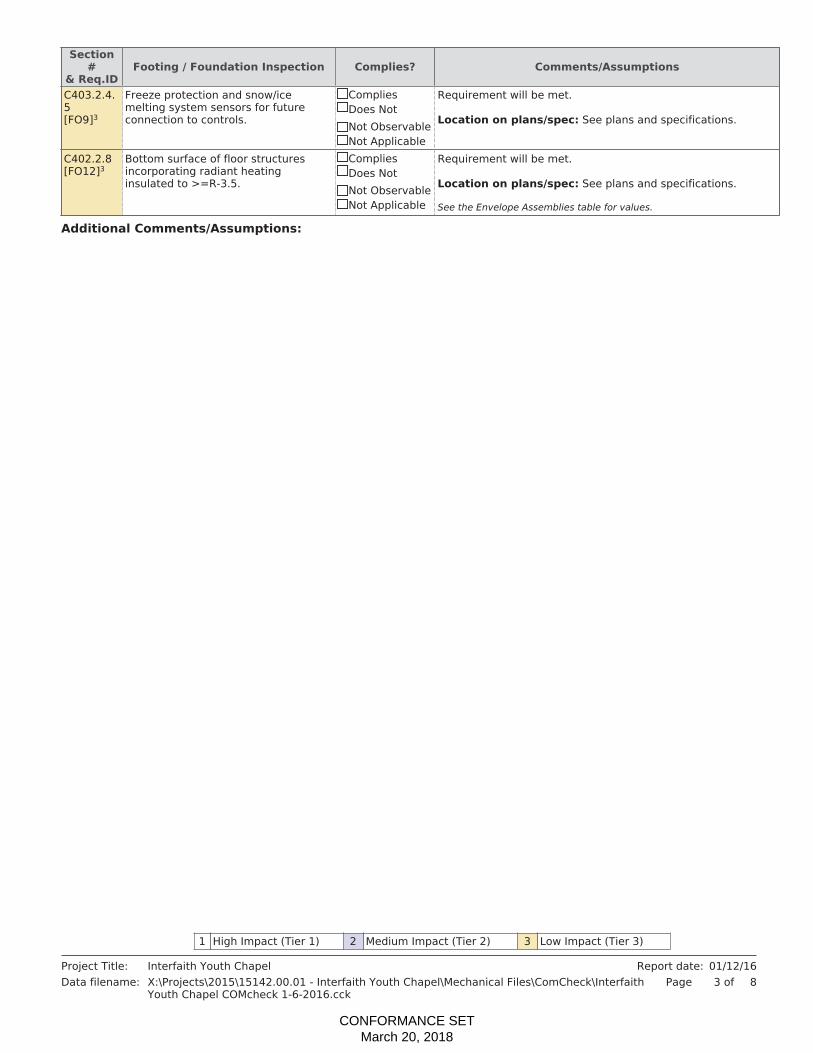
CONFORMANCE SETMarch 20, 2018

CONFORMANCE SETMarch 20, 2018

CONFORMANCE SETMarch 20, 2018

CONFORMANCE SETMarch 20, 2018

CONFORMANCE SETMarch 20, 2018

CONFORMANCE SETMarch 20, 2018
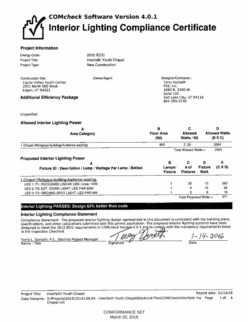
CONFORMANCE SETMarch 20, 2018
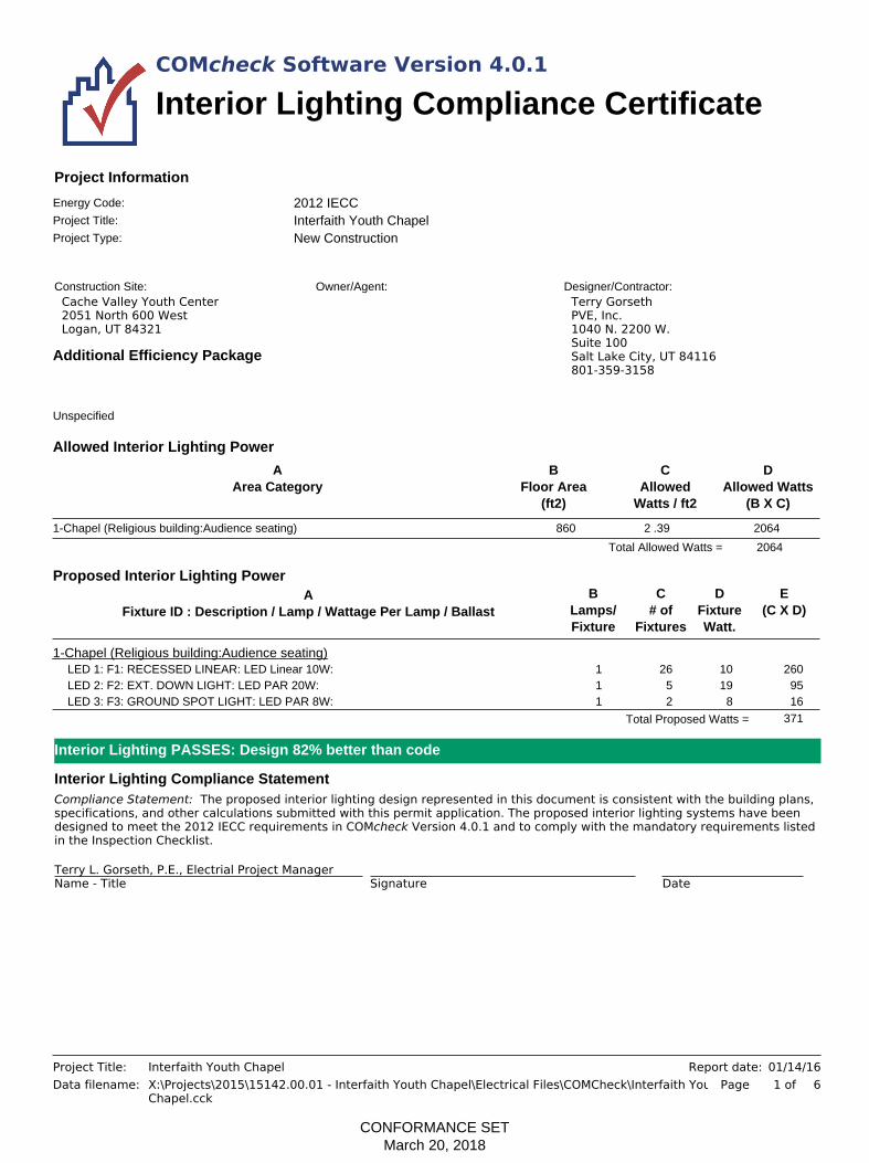
COMcheck Software Version 4.0.1
Interior Lighting Compliance Certificate
Project Title:
2012 IECC
Project Type: New Construction
Construction Site:Cache Valley Youth Center2051 North 600 WestLogan, UT 84321
Owner/Agent: Designer/Contractor:Terry GorsethPVE, Inc.1040 N. 2200 W.Suite 100Salt Lake City, UT 84116801-359-3158
Project Information
Energy Code:
Interfaith Youth Chapel
Unspecified
Additional Efficiency Package
Allowed Interior Lighting Power
AArea Category
BFloor Area
(ft2)
CAllowed
Watts / ft2
DAllowed Watts
(B X C)
1-Chapel (Religious building:Audience seating) 860 2 2064.39
2064Total Allowed Watts =
Proposed Interior Lighting PowerE
(C X D)D
FixtureWatt.
AFixture ID : Description / Lamp / Wattage Per Lamp / Ballast
BLamps/Fixture
C# of
Fixtures
1-Chapel (Religious building:Audience seating)LED 1: F1: RECESSED LINEAR: LED Linear 10W: 1 26 10 260LED 2: F2: EXT. DOWN LIGHT: LED PAR 20W: 1 5 19 95LED 3: F3: GROUND SPOT LIGHT: LED PAR 8W: 1 2 8 16
371Total Proposed Watts =
Interior Lighting Compliance StatementCompliance Statement: The proposed interior lighting design represented in this document is consistent with the building plans,specifications, and other calculations submitted with this permit application. The proposed interior lighting systems have beendesigned to meet the 2012 IECC requirements in COMcheck Version 4.0.1 and to comply with the mandatory requirements listedin the Inspection Checklist.
Terry L. Gorseth, P.E., Electrial Project ManagerName - Title Signature Date
Interior Lighting PASSES: Design 82% better than code
Project Title:Data filename:
Interfaith Youth ChapelX:\Projects\2015\15142.00.01 - Interfaith Youth Chapel\Electrical Files\COMCheck\Interfaith YouthChapel.cck
01/14/16Report date:61 ofPage
CONFORMANCE SETMarch 20, 2018

Inspection ChecklistRequirements: 0.0% were addressed directly in the COMcheck software
COMcheck Software Version 4.0.1
Text in the "Comments/Assumptions" column is provided by the user in the COMcheck Requirements screen. For eachrequirement, the user certifies that a code requirement will be met and how that is documented, or that an exceptionis being claimed. Where compliance is itemized in a separate table, a reference to that table is provided.
Energy Code: 2012 IECC
2012 IECC Plan Review Complies? Comments/Assumptions
C103.2[PR4]1
Plans, specifications, and/orcalculations provide all informationwith which compliance can bedetermined for the interior lightingand electrical systems and equipmentand document where exceptions tothe standard are claimed. Informationprovided should include interiorlighting power calculations, wattage ofbulbs and ballasts, transformers andcontrol devices.
CompliesDoes NotNot ObservableNot Applicable
C406[PR9]1
Plans, specifications, and/orcalculations provide all informationwith which compliance can bedetermined for the additional energyefficiency package options.
CompliesDoes NotNot ObservableNot Applicable
Additional Comments/Assumptions:
1 High Impact (Tier 1) 2 Medium Impact (Tier 2) 3 Low Impact (Tier 3)
Project Title:Data filename:
Interfaith Youth ChapelX:\Projects\2015\15142.00.01 - Interfaith Youth Chapel\Electrical Files\COMCheck\Interfaith YouthChapel.cck
01/14/16Report date:62 ofPage
CONFORMANCE SETMarch 20, 2018
2012 IECC Rough-In Electrical Inspection Complies? Comments/Assumptions
C405.2.2.1[EL22]2
Automatic controls to shut off allbuilding lighting installed in allbuildings.
CompliesDoes NotNot ObservableNot Applicable
C405.2.1.1[EL23]2
Independent lighting controls installedper approved lighting plans and allmanual controls readily accessible andvisible to occupants.
CompliesDoes NotNot ObservableNot Applicable
C405.2.1.2[EL15]1
Lighting controls installed to uniformlyreduce the lighting load by at least50%.
CompliesDoes NotNot ObservableNot Applicable
C405.2.2.3[EL16]2
Daylight zones provided withindividual controls that control thelights independent of general arealighting.
CompliesDoes NotNot ObservableNot Applicable
C405.2.3[EL17]3
Sleeping units have at least onemaster switch at the main entry doorthat controls wired luminaires andswitched receptacles.
CompliesDoes NotNot ObservableNot Applicable
C405.2.2.2[EL18]1
Occupancy sensors installed inrequired spaces.
CompliesDoes NotNot ObservableNot Applicable
C405.2.2.3[EL20]1
Primary sidelighted areas areequipped with required lightingcontrols.
CompliesDoes NotNot ObservableNot Applicable
C405.2.2.3[EL21]1
Enclosed spaces with daylight areaunder skylights and rooftop monitorsare equipped with required lightingcontrols.
CompliesDoes NotNot ObservableNot Applicable
C405.2.3[EL4]1
Separate lighting control devices forspecific uses installed per approvedlighting plans.
CompliesDoes NotNot ObservableNot Applicable
C405.3[EL19]3
Fluorescent luminaires with oddnumbered lamp configurations thatare with 10 feet center to center (ifrecess mounted) or are within 1 footedge to edge (if pendant or surfacemounted) shall be tandem wired.
CompliesDoes NotNot ObservableNot Applicable
C405.4[EL6]1
Exit signs do not exceed 5 watts perface.
CompliesDoes NotNot ObservableNot Applicable
C405.2.3[EL8]1
Additional interior lighting powerallowed for special functions per theapproved lighting plans and isautomatically controlled andseparated from general lighting.
CompliesDoes NotNot ObservableNot Applicable
Additional Comments/Assumptions:
1 High Impact (Tier 1) 2 Medium Impact (Tier 2) 3 Low Impact (Tier 3)
Project Title:Data filename:
Interfaith Youth ChapelX:\Projects\2015\15142.00.01 - Interfaith Youth Chapel\Electrical Files\COMCheck\Interfaith YouthChapel.cck
01/14/16Report date:63 ofPage
CONFORMANCE SETMarch 20, 2018

1 High Impact (Tier 1) 2 Medium Impact (Tier 2) 3 Low Impact (Tier 3)
Project Title:Data filename:
Interfaith Youth ChapelX:\Projects\2015\15142.00.01 - Interfaith Youth Chapel\Electrical Files\COMCheck\Interfaith YouthChapel.cck
01/14/16Report date:64 ofPage
CONFORMANCE SETMarch 20, 2018

2012 IECC Final Inspection Complies? Comments/Assumptions
C408.2.5.1[FI16]3
Furnished as-built drawings forelectric power systems within 30 daysof system acceptance.
CompliesDoes NotNot ObservableNot Applicable
C303.3,C408.2.5.2[FI17]3
Furnished O&M instructions forsystems and equipment to thebuilding owner or designatedrepresentative.
CompliesDoes NotNot ObservableNot Applicable
C405.5.2[FI18]1
Interior installed lamp and fixturelighting power is consistent with whatis shown on the approved lightingplans, demonstrating proposed wattsare less than or equal to allowedwatts.
CompliesDoes NotNot ObservableNot Applicable
See the Interior Lighting fixture schedule for values.
C408.3[FI33]1
Lighting systems have been tested toensure proper calibration, adjustment,programming, and operation.
CompliesDoes NotNot ObservableNot Applicable
C406[FI34]1
Efficient HVAC performance, efficientlighting system, or on-site supply ofrenewable energy consistent withwhat is shown the approved plans.
CompliesDoes NotNot ObservableNot Applicable
Additional Comments/Assumptions:
1 High Impact (Tier 1) 2 Medium Impact (Tier 2) 3 Low Impact (Tier 3)
Project Title:Data filename:
Interfaith Youth ChapelX:\Projects\2015\15142.00.01 - Interfaith Youth Chapel\Electrical Files\COMCheck\Interfaith YouthChapel.cck
01/14/16Report date:65 ofPage
CONFORMANCE SETMarch 20, 2018

Project Title:Data filename:
Interfaith Youth ChapelX:\Projects\2015\15142.00.01 - Interfaith Youth Chapel\Electrical Files\COMCheck\Interfaith YouthChapel.cck
01/14/16Report date:66 ofPage
CONFORMANCE SETMarch 20, 2018


![Project 08[1].04](https://static.fdocuments.in/doc/165x107/577d21281a28ab4e1e94a0b4/project-08104.jpg)