Project-Based Curriculum for Teaching Analytical Design to...
25
education sciences Article Project-Based Curriculum for Teaching Analytical Design to Freshman Engineering Students via Reconfigurable Trebuchets Daniel R. Herber 1 , Anand P. Deshmukh 1 , Marlon E. Mitchell 2 and James T. Allison 1, * 1 Department of Industrial and Enterprise Systems Engineering, University of Illinois at Urbana-Champaign, 104 S. Mathews Ave., Urbana, IL 61801, USA; [email protected] (D.H.); [email protected] (A.D.) 2 Department of Curriculum and Instruction, University of Illinois at Urbana-Champaign, 1310 S 6th St, Champaign, IL 61820, USA; [email protected] * Correspondence: [email protected]; Tel.: +1-217-244-4319 Academic Editor: James Albright Received: 22 December 2015; Accepted: 14 February 2016; Published: 25 February 2016 Abstract: This paper presents an effort to revitalize a large introductory engineering course for incoming freshman students that teaches them analytical design through a project-based curriculum. This course was completely transformed from a seminar-based to a project-based course that integrates hands-on experimentation with analytical work. The project is centered on a reconfigurable trebuchet kit that student groups assemble and work to identify design decisions that will maximize projectile launch distance. Challenges include streamlining the project experience for the large enrollment (up to 148 students) with limited contact hours, and helping students fuse hands-on experiences with quantitative engineering analysis. A mixed-methods approach supported the claim that the curriculum improved the students’ engineering judgment and demonstrated to students the value of engineering analysis and mathematical models in practical engineering design. A rigorous statistical analysis of student trebuchet launch performance at different course stages is included. A qualitative assessment of student learning is derived through students’ reflection of their course experience. Comprehensive results comparing students’ design iterations versus algorithmic design optimization iterations provide important insights into student design intuition, paving the way for hybrid design education models that teach students how to combine human design intuition with quantitative design tools to design superior systems. Keywords: project-based learning; engineering judgment; design education; engineering education; trebuchets; reconfigurable kits; interactive computer models; model-based design 1. Introduction Traditional engineering design courses often have relied on happenstance to link theory with practice. Noticing these deficits in student practical engineering design experience, the Department of Industrial and Enterprise Systems Engineering at University of Illinois at Urbana-Champaign decided to revamp its freshman-level engineering course by introducing a project-based curriculum. The premise was that a project-based, hands-on activity that was connected carefully with quantitative engineering analysis would introduce students to the rigors of engineering design practice at an early stage in their engineering career, along with other benefits. Educ. Sci. 2016, 6, 7; doi:10.3390/educsci6010007 www.mdpi.com/journal/education
Transcript of Project-Based Curriculum for Teaching Analytical Design to...
education sciences
Article
Project-Based Curriculum for Teaching AnalyticalDesign to Freshman Engineering Students viaReconfigurable Trebuchets
Daniel R. Herber 1, Anand P. Deshmukh 1, Marlon E. Mitchell 2 and James T. Allison 1,*1 Department of Industrial and Enterprise Systems Engineering, University of Illinois at
Urbana-Champaign, 104 S. Mathews Ave., Urbana, IL 61801, USA; [email protected] (D.H.);[email protected] (A.D.)
2 Department of Curriculum and Instruction, University of Illinois at Urbana-Champaign, 1310 S 6th St,Champaign, IL 61820, USA; [email protected]
* Correspondence: [email protected]; Tel.: +1-217-244-4319
Academic Editor: James AlbrightReceived: 22 December 2015; Accepted: 14 February 2016; Published: 25 February 2016
Abstract: This paper presents an effort to revitalize a large introductory engineering coursefor incoming freshman students that teaches them analytical design through a project-basedcurriculum. This course was completely transformed from a seminar-based to a project-basedcourse that integrates hands-on experimentation with analytical work. The project is centeredon a reconfigurable trebuchet kit that student groups assemble and work to identify designdecisions that will maximize projectile launch distance. Challenges include streamlining the projectexperience for the large enrollment (up to 148 students) with limited contact hours, and helpingstudents fuse hands-on experiences with quantitative engineering analysis. A mixed-methodsapproach supported the claim that the curriculum improved the students’ engineering judgmentand demonstrated to students the value of engineering analysis and mathematical models inpractical engineering design. A rigorous statistical analysis of student trebuchet launch performanceat different course stages is included. A qualitative assessment of student learning is derivedthrough students’ reflection of their course experience. Comprehensive results comparing students’design iterations versus algorithmic design optimization iterations provide important insights intostudent design intuition, paving the way for hybrid design education models that teach studentshow to combine human design intuition with quantitative design tools to design superior systems.
Keywords: project-based learning; engineering judgment; design education; engineering education;trebuchets; reconfigurable kits; interactive computer models; model-based design
1. Introduction
Traditional engineering design courses often have relied on happenstance to link theory withpractice. Noticing these deficits in student practical engineering design experience, the Departmentof Industrial and Enterprise Systems Engineering at University of Illinois at Urbana-Champaigndecided to revamp its freshman-level engineering course by introducing a project-based curriculum.The premise was that a project-based, hands-on activity that was connected carefully withquantitative engineering analysis would introduce students to the rigors of engineering designpractice at an early stage in their engineering career, along with other benefits.
Educ. Sci. 2016, 6, 7; doi:10.3390/educsci6010007 www.mdpi.com/journal/education
Educ. Sci. 2016, 6, 7 2 of 25
1.1. Project-Based Learning via Trebuchets
Project-Based Learning (PBL) is a teaching method in which students gain knowledge and skillsby working for an extended period of time to investigate and respond to an engaging and complexquestion, problem, or challenge [1]. Simply put, project-based learning conveys learning throughexperiences [2]. PBL curricula are designed in a way in which students work in groups to solvechallenging issues that are authentic in nature but based within a curriculum [3,4].
Over the past several years, the United States has experienced a shortage of qualified engineers.Being cognizant of this fact, the U.S. National Science Foundation (NSF) called for reform inengineering education [5]. This call for reform included and emphasized project-based learning.PBL encourages self-directed learning that in turn supports life-long learning (which links intothe department’s overarching goal). That ultimate goal is to provide students with the requiredknowledge base and necessary skill set, while also helping students develop attitudes that supportbecoming efficient and effective engineers.
The PBL authentic approach [6] was introduced to the curriculum via a reconfigurable trebuchetkit. A trebuchet is a machine that converts gravitational potential energy to kinetic energy to launcha projectile. These kits and associated curriculum were designed to enhance student engagement,participation, and motivation, which are keys to linking theory to practice in engineering analysisand design. Students were presented with situations that required them to become active learnersrather than relying on the rote methods of lecture [7]. Research has found that implementationof project-based lab activities into engineering design courses help bridge the gap between theoryand practice [6]. Other available research suggests that PBL courses appear to improve retention,student satisfaction, diversity, student learning [8], and provide beneficial ‘soft skill’ development forstudents [9].
Many PBL activities employ open-ended projects that are especially helpful in aidingdevelopment of synthesis skills and creative idea generation and exploration. When theseopen-ended PBL projects include a significant design element they are sometime referred to asdesign-based learning (DBL). Thus, DBL is a type of project-based learning which involves studentsengaged in the process of developing, building, and evaluating a product they have designed [10].Open-ended projects, however, often are time and resource intensive, may require significantprerequisite coursework to obtain the necessary tools, and often are difficult to connect with rigorousengineering analysis except in capstone or graduate-level projects. More structured projects supportstreamlined learning activities that are less time and resource intensive but are appropriate forlearning objectives that are different from open-ended projects (including integration of analysis).For example, open-ended engineering design projects support learning important elements of designprocesses, such as problem identification and formulation, design concept generation, trade-offnegotiation, and project management. Many argue design is fundamentally open ended [11].In cases where students have sufficient technical preparation (e.g., upper-division engineeringanalysis courses) and ample time is available, open-ended design projects may also provide studentswith opportunities to learn the important connection between engineering design practice andrigorous engineering analysis. The specific course addressed in this article, however, is a first-yearundergraduate engineering course that meets for only one hour per week. Time limitations andlack of deep technical background constrain PBL activities for this type of course. Discoveringhow engineering analysis supports engineering design practice, however, provides vital context forfirst-year undergraduates as they begin a sequence of challenging courses in fundamental scienceand engineering analysis. Given these constraints, how then can educators help beginning studentsexperience the relationship between analysis and engineering practice? Many first-year PBL coursesneglect rigorous analytic design in favor of more tangible activities on open-ended design problems(differentiating our approach from classical DBL activities). While these strategies produce valuablelearning outcomes, a need exists for integrating analysis into design learning at early stages ofeducation. Our hypothesis here is that a structured PBL curriculum with targeted learning outcomes
Educ. Sci. 2016, 6, 7 3 of 25
provides an efficient and engaging learning strategy that addresses the interface between engineeringanalysis and practice.
The pedagogical approach proposed here aims to help students develop a specific understandingof the synergistic relationship between engineering analysis and practical engineering knowledgeand intuition. In the simplest terms, intuition may correspond to simplified mental models orheuristics. It is helpful for an engineer to have good mental models based on experience and practicalunderstanding of engineering systems, but it is also important for them to understand the limitationsof these mental models [12]. Relying solely on intuitive mental models can lead to design fixationespecially in case of inexperienced engineers where they may intuitively hold false assumptions aboutthe system being designed, abide by nonexistent limitations, feel overwhelmed or have incompleteor partial information [13]. The design fixation can be mitigated through design exploration basedon rigorous analysis or experimentation which can then feed back into strengthening these mentalmodels and making them more sophisticated or accurate [14–16]. One such rigorous strategy iscontinuous engineering design optimization, which is an important design methodology for manyengineering applications [17]. Introducing students to both intuition-based and quantitative designdecision strategies is important, especially early in their engineering education.
The integration of engineering intuition and analysis is referred to in this work as engineeringjudgment. Although there is no clear definition for engineering judgment in the literature, ourdefinition is based on the approach proposed in Ref. [12]. Here we define engineering judgment as theability to utilize simultaneously practical engineering intuition and quantitative engineering analysisto support improved engineering decisions. A primary learning objective is to provide first-yearstudents with a solid foundation for the development of their own engineering judgment, whichwill be built upon though later coursework. An additional objective is to provide students with aproper perspective on how content in upcoming courses, focused on fundamentals and quantitativeanalytical tools, relates to finding solutions to real engineering problems. A lean curriculum wasdeveloped with targeted learning activities centered on a structured design project. This projectinvolves trebuchet kits that are assembled by students, and that can be reconfigured to changedynamic behavior in complicated ways. Reconfigurable capability provides an opportunity forstudents to make design decisions without the need to construct one or more physical prototypesfrom scratch. While there is certainly value in open-ended design and fabrication activities, theseare provided in other courses. The focus here is instead on making design decisions supported byquantitative engineering analysis. Students learn to improve their designs through physics-basedunderstanding of the system, and through rational application of modern simulation-based tools.The use of trebuchets in classrooms is certainly not a novel idea. Using trebuchets as a means tounderstand the relationship between challenging practical design decisions and rigorous analyticaltools, however, is.
1.2. Previous Pedagogical Use of Trebuchets
Trebuchets or other projectile-throwing, simple machines are commonly used by educatorsin PBL activities or for demonstrations. The accessibility of trebuchets permits activities wherestudents at a variety of levels can engage (even beyond engineering and science related courses [18]).Engineering upperclassmen [18–20], engineering freshman [21–23], high school students [24,25],middle school students [26], and even K–5 students (as the authors have personally experienced)are all levels of education where trebuchet-based learning activities have played some part.
Many of the reported activities have curricula developed around different learning objectivesand trebuchet kits/models not suitable for analytical design activities. Open-ended trebuchetactivities and rigorous analytical design exploration do not need to be mutually exclusive activities;however, much of the students’ time during open-ended activities tends to be occupied withimportant, creative tasks (which are more qualitative in nature) than quantitative exploration oftheir proposed trebuchet design [22,24,26]. Since teaching analytical design methods is not one of

Educ. Sci. 2016, 6, 7 4 of 25
the primary goals of these activities, it is not surprising that only a limited amount of time is spentmodeling and perfecting their designs.
Computer models of trebuchets [20,25] facilitate rapid design iteration through model-baseddesign strategies. Using mathematical optimization tools in conjunction with computer models toidentify high-performance designs is an especially powerful strategy [20,27]. For these efforts tocorrespond to actual trebuchet design problems, the models and design problems must be based onrealistically tunable design variables. For example, adjusting the projectile release angle is convenientfrom a modeling perspective, but this cannot be adjusted directly on a physical trebuchet. Realisticallytunable parameters that influence release angle should be chosen instead as design variables. Inaddition, computer models can be used jointly with physical trebuchets to demonstrate the value ofmodel-based design when compared to design exploration through physical testing [20,25].
The variety of trebuchet-based learning activities were shown to achieve a variety of importantoutcomes, including helping students to connect theoretical course material to realistic engineeringdesign problems [21], improving inclination towards continuing in a STEM field [24], and improvingproblem-solving skills [19]. Here we build on the efforts described in the above literature through thedevelopment of a trebuchet-based activity focused on teaching analytical design.
1.3. Transition from Seminar-Based Course
Considering the benefits of PBL, an introductory freshman course, GE 100, was completelyredesigned in fall 2012 to help students experience the range of technical topics covered in thedepartment using a single hands-on project, and begin to develop engineering judgment. Before fall2012, GE 100 was a 1 h, seminar-based course consisting of overview lectures provided by departmentfaculty. While students were exposed to a wealth of important information, the course on the wholedid not engage students, and did little to prepare them for the upcoming rigorous curriculum. Eachlecture was delivered by a different faculty member with varying levels of engagement and utility forfirst-year students. The revised course maintained the same session format: 50 min meetings everyweek for half a semester (eight weeks for a total of 6.7 h). This limited direct contact with the studentspresented an additional challenge when developing an appropriate course curriculum.
1.4. Curriculum Overview
In the redesigned GE 100 student project groups assemble, design, and test medium-scaletrebuchets as part of the project (see Table 1 for the curriculum outline). Reconfigurable trebuchetkits were developed that supported a streamlined yet intensive hands-on experience. Studentgroups (3–5 students each) followed technical instructions to use hand tools to assemble completetrebuchets from components provided in kits (meetings 1 and 2). Students also learned how to adjustseveral components, such as pivot location, as a means to influence trebuchet dynamic behaviorand projectile range. The reconfigurability of these components is a novel feature of these new kits,and is crucial for the use of these kits in teaching different approaches for engineering design. Thedesign problem presented to students is to determine what is the best setting for four adjustabletrebuchet components for maximizing projectile range. This is challenging to solve using intuitionalone due to the dimension of the design problem (four correlated design variables), uncertainty inthe trebuchet mechanisms and the operating environment (outdoors), and the significant nonlinearityof the overall system.
Early in the course, GE 100 students learn basic design of experiments (DOE) techniques(meeting 2). With this knowledge and some initial intuition stemming from hands-on explorationof the trebuchets, students are then asked to plan out a set of experiments. Each experiment is adistinct trebuchet design (i.e., combination of settings for reconfigurable variables) that the studentswould like to test physically. The number of physical tests is limited severely because the tests areconducted outdoors during class time, and adjustments must be made between tests. Over thecourse of several semesters, the trebuchet kits have been refined iteratively to streamline assembly

Educ. Sci. 2016, 6, 7 5 of 25
Table 1. Curriculum outline.
Meeting Week Type Name
1 1 Hands-on Trebuchet Assembly2 2 Hands-on Trebuchet Assembly and DOE Activity3 4 Lecture Process Design Overview4 6 Hands-on Field Day #15 7 Lecture Trebuchet Physics Overview6 7 Hands-on Model-based Design Activity7 8 Hands-on Field Day #28 11 Lecture Project Analysis and Reflection
and reduce adjustment time, but the time required to make adjustments still limits the total numberof experiments that each project group can perform. During this initial set of experiments, thestudents have very limited design intuition for the trebuchets, so their experiments are often designedto sample the trebuchet design space broadly (i.e., students use a space-filling experiment design,see Figure 1). During this activity, a handout required students to perform the following activitiesin order:
1. Rank the design variables from 1 to 4 in order of importance;2. Identify variable ranges (min and max) that you would like to test using the physical trebuchet
kit for guidance;3. Plan for a budget of eight total experiments with suggestions for space-filling experiments.
These tasks provided an introduction to the systematic process of designing experiments.
x1x2
x3
x1: sling length
x2:fingerangle
x1: sling length
x3:pivotposition
x2: finger angle
x3:pivotposition
Figure 1. Space-filling Latin Hypercube sampling plan with three variables and eight sample points [28].
The first lecture provides an overview of both the course and the department. An introductionto process modeling is also given during this first lecture (meeting 3). A logistics model wascreated that combines agent-based modeling [29] and discrete-event modeling [30] to simulate howstudent groups rotate through trebuchet tests on field days (outdoor test days). Process modelinghelps introduce students to some of the department’s courses and core research areas, provides anadditional modeling experience beyond physics-based models, and familiarizes students with thefield day logistics. The next meeting with the students was the first outdoor field day (meeting 4)where students execute tests specified during the DOE activity, following logistics policies refinedusing the model.
After the first field day tests, students learn in class about the physics of trebuchets, the basicsof simulating nonlinear dynamic systems, and model-based design (meeting 5). This instructionis followed-up with a computer modeling lab where students are introduced to a sophisticatedphysics-based, multibody dynamic trebuchet model that predicts projectile range as a function oftrebuchet design variable values (meeting 6). During this modeling lab project groups use this modelto test new design ideas much more rapidly than through physical experiments. Student realize
Educ. Sci. 2016, 6, 7 6 of 25
quickly the value of using physics-based models in engineering design. Due to the rapid responsefrom the model, most student groups are able to develop intuition for the influence of design changesand converge on a near-optimal trebuchet design. During this activity, a handout required studentsto perform the following activities in order:
1. Perform three predefined tests and report the distance;2. Answer the following question: “What is a good finger angle when sling length is 26 in and the
pivot location is 4 in? Why?” (which is a single variable optimization problem);3. Rank the design variables from 1 to 4 in order of importance (repeat from the DOE activity);4. Plan for a budget of six total experiments for field day #2;5. (optional) Test more designs at home.
A new experiment design is constructed based on the insights gained from the first field dayexperiments and the computer modeling activity. The new experimental plan is fundamentallydifferent from the first; trebuchet designs to be tested are clustered around the design that waspredicted to be optimal during the modeling lab. The purpose of the clustered experimental planis to account for modeling error and improve the chances of producing the best possible range fora physical trebuchet test. With the new experimental plan, the students then go back out to the testarea for a second test launch activity (meeting 7). The student groups largely experience a dramaticimprovement in the performance of their trebuchet designs.
The final meeting (8) was devoted to analysis and reflection on the previous seven meetings.This meeting included the following activities:
1. Review of both quantitative and qualitative results from all of the project activities, includinganalysis of experimental results;
2. Comparison of variable rankings based on student intuition (before and after the modeling lab);3. Discussion on the effectiveness of the launch day movement policies and comparison with
multi-agent modeling results;4. Exploration of a comprehensive data set based on the trebuchet model to more fully understand
the trebuchet design problem and the complex tradeoffs involved;5. Discussion on the explicit reasons for why engineering students take math and engineering
analysis courses and how these topics are directly useful in engineering practice;6. Asking students their definitions of engineering intuition and judgment, and how course
activities influenced their understanding of these ideas;7. Discussion on the value and potential problems with using modeling and simulation in
engineering practice;8. Engaging students in a discussion on what they learned about developing a systems perspective
for engineering design;9. Review of a variety of strategies for engineering design, including their different levels of
analytical rigor, as well as the role of human creativity across all design strategies.
Many of these points are further elaborated in the following sections.
1.5. Learning Objectives
This sequence of activities provides students with first-hand experience that demonstrates thevalue of mathematical and physics-based knowledge in practical engineering design activities, andalso capitalizes on the value of hands-on experiences to deepen student learning. Students gainvaluable insights into why it is essential for engineers to learn foundational topics in mathematicsand science. It is our objective to provide students at the very beginning of their college educationwith a solid understanding of how fundamental analysis courses required at early stages of theireducation provide an important foundation for later design courses, and how these courses will helpprepare them to become successful engineers.

Educ. Sci. 2016, 6, 7 7 of 25
In the subsequent sections, we discuss the trebuchet kits used in this curriculum followed bya description of computational model used to explore the design space. Lastly we present theperceived improvement in the students’ engineering judgment outcomes due to the inclusion of thisproject-based trebuchet activity, supported by the rigorous statistical analysis. Engineering judgmenthere refers to the ability to utilize simultaneously practical engineering intuition and quantitativeengineering analysis to support improved engineering decisions.
2. Reconfigurable Trebuchet Kits
In this section, we describe the design of customized trebuchet kits used by students in thisredesigned GE 100 course. The primary motivation for designing these kits in-house was due tounavailability of commercial trebuchet kits that provided the adjustability needed to allow studentsto make design decisions. A new reconfigurable trebuchet kit was designed that allows continuousadjustments to pivot position, sling length, and finger angle (see Figure 2a). The kits also supportone discrete design decision: whether or not wheels are used on the trebuchet base. The kits weredesigned for durability, ease of use by students (streamlined assembly and adjustments), and easeof fabrication (no specialized equipment required). Engineering drawings, course materials, andsoftware models have been made freely available so that other institutions may use this project asa teaching aid. We now look briefly at some of the design aspects of these trebuchet kits. A numberof factors shaped the final design of the trebuchet:
• Reproducibility across trebuchet kits for fair comparisons and use with a computer model;• Reconfigurable capability to support rapid student adjustment of design variables (under 5 min);• Streamlined assembly process, enabling most student groups to complete assembly process in
less than 40 min given written instructions, components, fasteners, and tools;• Portability (two college-level students can transport them small distances);• Durability (multiple years of use, rain/weather protection);• Reasonable cost (approximately $150 per kit, including all materials, hardware, tools, and
manufacturing tools).
A CAD drawing of an assembled trebuchet is shown in Figure 2a. During operation, the userplaces a soft clay projectile in the pouch at the end of the sling, raises the counterweight to itsmaximum vertical position, positions the projectile on the base being careful to remove sling slack,and then releases the counterweight to initiate projectile launch. As the weight moves down in curvedmotion it swings the sling up and forward. One end of the sling is a loop that slid over the “finger”.The finger angle (one of the adjustments) determines the point at which the sling loop slides off thefinger, releasing the projectile. The finger angle influences both the launch angle and velocity. Otheradjustments also influence the point at which the sling slides off the finger.
Wheels (On/O↵)
Finger Angle�40� ! 40� Pivot Position
0 in ! 8 in
Sling Length5 in ! 35 in
(a)
Figure 2. Cont.

Educ. Sci. 2016, 6, 7 8 of 25
1
1
2
2
3
3
4
4
A A
B B
C C
D D
SHEET 1 OF 1
DRAWN
CHECKED
QA
MFG
APPROVED
esdl 7/19/2014
DWG NO
TITLE
SIZE
CSCALE
REV
counterweightthrowing arm
direction of rotationwhen released
0 inch fulcrum position8 inch fulcrum position
fulcrum position
positive finger anglefulcrum
negative finger angle
+ ✓
� ✓
(b)
Figure 2. Reconfigurable trebuchet kit. (a) CAD drawing of trebuchet illustrating the four designvariables; (b) measuring conventions for finger angle and pivot position.
Students can make four distinct trebuchet adjustments to influence dynamic behavior andprojectile range. These four adjustments (design variables) are detailed in Table 2.
Table 2. Reconfigurable design variables for trebuchet kits, with lower and upperbound specifications.
Name Type LB UB
x1 Sling Length Continuous 5 in 35 inx2 Finger Angle Continuous −40◦ 40◦
x3 Pivot Position Continuous 0 in 8 inx4 Wheels Discrete On Off
The first three design variables are continuous while the fourth is discrete (the design can eitherhave four wheels attached at the base or not). Variable upper and lower bounds were provided to thestudents to help them understand the range of values that could be used for the continuous designvariables. The measuring conventions for x2 and x3 are shown in Figure 2b.
The assembly steps and design variable adjustments require some basic tools. These wereprovided for each trebuchet kit in the form of a toolbox (see Figure 3(a)). This toolbox containedtwo nutdrivers, two adjustable wrenches, a hammer, a protractor, and a tape measure. The toolboxalso served as storage for the fasteners and smaller parts.
(a) (b)
Figure 3. Photographs of a student toolkit and a trebuchet. (a) toolbox and select tools for assemblyand design variable readjustments; (b) assembled trebuchet.
Note that some of the parts are preassembled such as the shoulder (part A in Figure 4) andcaster or wheel (part C). Students had a limited amount of time to assemble trebuchet kits in class,so some limited preassembly was used to reduce total assembly time. The students are provided

Educ. Sci. 2016, 6, 7 9 of 25
assembly instructions with both a written description and simple drawings that illustrate assemblysteps. In addition, a mentor (graduate student or senior undergraduate student) was available if thestudents had any questions. The six assembly steps are illustrated in Figures 4 and 5.
Each trebuchet kit has a counterbalance mass consisting of two 10 lbs plates (part D). One ofthe assembled trebuchets is shown in Figure 3(b). The trebuchet body is approximately 36 incheslong, 11 inches wide and 22 inches tall. The throwing arm (without finger) is approximately 36 incheslong. The trebuchet parts such as base (part B), shoulders, and throwing arm (part G) are all made ofwood. Most wood components are pine, although high-stress components (such as the throwing arm,finger, and main uprights) are oak. The pivot rod (part 6), pins, and fasteners are made of steel. Thelooping clamp mechanism that simplifies sling length adjustment, and the mounting seats for casters(shown in Figure 6g) were both fabricated via 3D printing (polymer fusion deposition modeling).The 3D printed caster mounting seats streamlined assembly and reduced the time required to switchbetween with and without wheels configurations. These seats enable assembly with a single largecentral bolt instead of four machine screws.
D
D
H
12
12
5
5
3
37
G
1
1
2
2
3
3
4
4
A
A
B
B
C
C
D
D
SHEE
T 1
OF
1
DRAW
N
CHEC
KED
QA MFG AP
PRO
VED
Jenn
ifer
Woo
7/11
/201
4
DWG
NO
TITL
E SIZE C
SCAL
E
REV
1
1
2
2
3
3
4
4
A
A
B
B
C
C
D
D
SHEET 1 OF 1
DRAWN
CHECKED
QAM
FGAPPROVED
Jennifer Woo
7/11/2014
DWG NO
TITLE
SIZECSCALE
REV
1
1
2
2
3
3
4
4
AA
BB
CC
DD
SHEET 1 OF 1
DRAWN
CHECKED
QA
MFG
APPROVED
Jennifer Woo7/11/2014
DWG NO
TITLE
SIZE
CSCALE
REV
1
1
2
2
3
3
4
4
A A
B B
C C
D D
SHEET 1 OF 1
DRAWN
CHECKED
QA
MFG
APPROVED
Jennifer Woo 7/11/2014
DWG NO
TITLE
SIZE
CSCALE
REV
6⇥
41
110
AA
B
B
C
4
4⇥
1
1
2
2
3
3
4
4
A A
B B
C C
D D
SHEET 1 OF 1
DRAWN
CHECKED
QA
MFG
APPROVED
Jennifer Woo 7/11/2014
DWG NO
TITLE
SIZE
CSCALE
REV
8
1
2
3
Figure 4. Drawings illustrating steps 1–3 in the assembly instructions. Step (1) involves fastening ofcasters to the trebuchet base. Step (2) illustrates attachment of upright shoulders to the base. Step (3)involves assembly of the pivot mechanism and attachment of the counterweights.
Educ. Sci. 2016, 6, 7 10 of 25
G
41
E2
1
F1
9
1
1
2
2
3
3
4
4
A A
B B
C C
D D
SHEET 1 OF 1
DRAWN
CHECKED
QA
MFG
APPROVED
Jennifer Woo 7/11/2014
DWG NO
TITLE
SIZE
CSCALE
REV
1
1
2
2
3
3
4
4
A A
B B
C C
D D
SHEET 1 OF 1
DRAWN
CHECKED
QA
MFG
APPROVED
Jennifer Woo 7/11/2014
DWG NO
TITLE
SIZE
CSCALE
REV
Sling Cord
Loop
F
Sling Length
Pouch
Clay Ball E
11
6
11
45
6
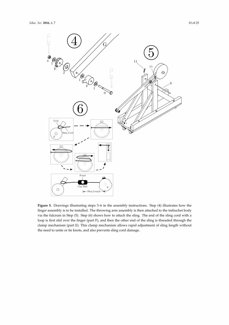
Figure 5. Drawings illustrating steps 3–6 in the assembly instructions. Step (4) illustrates how thefinger assembly is to be installed. The throwing arm assembly is then attached to the trebuchet bodyvia the fulcrum in Step (5). Step (6) shows how to attach the sling. The end of the sling cord with aloop is first slid over the finger (part F), and then the other end of the sling is threaded through theclamp mechanism (part E). This clamp mechanism allows rapid adjustment of sling length withoutthe need to untie or tie knots, and also prevents sling cord damage.
Educ. Sci. 2016, 6, 7 11 of 25
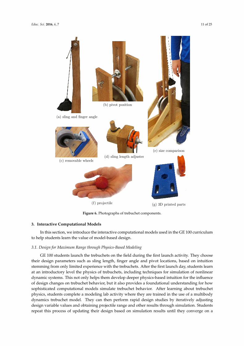
(b) pivot position
(c) removable wheels(d) sling length adjuster
(e) size comparison
(a) sling and finger angle
(f) projectile (g) 3D printed parts
Figure 6. Photographs of trebuchet components.
3. Interactive Computational Models
In this section, we introduce the interactive computational models used in the GE 100 curriculumto help students learn the value of model-based design.
3.1. Design for Maximum Range through Physics-Based Modeling
GE 100 students launch the trebuchets on the field during the first launch activity. They choosetheir design parameters such as sling length, finger angle and pivot locations, based on intuitionstemming from only limited experience with the trebuchets. After the first launch day, students learnat an introductory level the physics of trebuchets, including techniques for simulation of nonlineardynamic systems. This not only helps them develop deeper physics-based intuition for the influenceof design changes on trebuchet behavior, but it also provides a foundational understanding for howsophisticated computational models simulate trebuchet behavior. After learning about trebuchetphysics, students complete a modeling lab activity where they are trained in the use of a multibodydynamics trebuchet model. They can then perform rapid design studies by iteratively adjustingdesign variable values and obtaining projectile range and other results through simulation. Studentsrepeat this process of updating their design based on simulation results until they converge on a

Educ. Sci. 2016, 6, 7 12 of 25
design that they are satisfied with. In addition to helping students arrive at a significantly improveddesign, this modeling lab was also shown to help students improve qualitative understanding andintuition for trebuchet system design.
The physics-based simulation model for trebuchet was developed in MATLAB R© andSIMMECHANICSTM software. The software interface for this simulation model is shown in Figure 7.The goal of providing students with a computer simulation model is to help them experience directlythe importance of model-based design in the overall design process. It helps them to develop moreaccurate intuition through rapid creative exploration of the design space, and demonstrates throughexperience the value of rapid simulations when striving to solve a design problem quickly [31], andto identify better designs than can be achieved through slower physical testing.
Figure 7. Graphical user interface for simulation model.
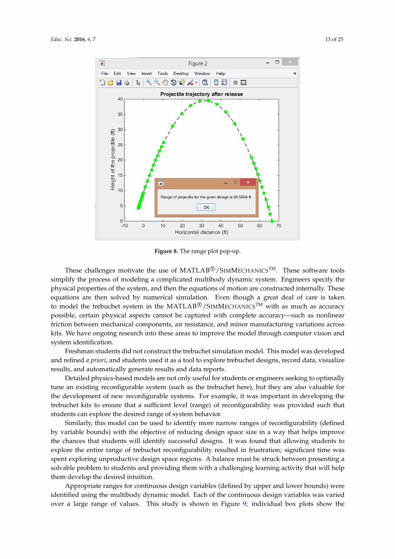
The simulation model is used by students to explore the design space and to discover the relativeimportance of design variables on improving range. This intuition helps students identify designsquickly that maximize range according to simulated results. The produces two important outputs:(1) predicted throwing range for a given design and the predicted path of projectile as shown inFigure 8; and (2) an animation of trebuchet motion during the sling launch as shown in Figure 7. Thisrich set of outputs is designed to help students gain insight into how the system behaves, and howdesign changes influence specific aspects of dynamic behavior.
While the trebuchet system appears to be mechanically simple, its underlying equations ofmotion are highly nonlinear due to large-angle rotations of the throwing arm and sling. This systemalso involves multiple bodies with irregular inertias such as the base, arm, counterbalance weights,wheels, and other components. The governing differential equations for the trebuchet system cannotbe solved in closed-form [32], so must be solved via numerical simulation. The trebuchet modelis further complicated in the case where wheels are attached and the base moves relative to theground during launch. Another complication is the sliding contact between the projectile and thebase (i.e., where it slides before being lifted off and slung forward by the arm). The launch processinvolve three distinct phases separated by two discrete events: (1) when the projectile lifts off the base;and (2) when the projectile is released. This results in a hybrid dynamic system [33] with three phases.
Educ. Sci. 2016, 6, 7 13 of 25
Figure 8. The range plot pop-up.
These challenges motivate the use of MATLAB R©/SIMMECHANICSTM. These software toolssimplify the process of modeling a complicated multibody dynamic system. Engineers specify thephysical properties of the system, and then the equations of motion are constructed internally. Theseequations are then solved by numerical simulation. Even though a great deal of care is takento model the trebuchet system in the MATLAB R©/SIMMECHANICSTM with as much as accuracypossible, certain physical aspects cannot be captured with complete accuracy—such as nonlinearfriction between mechanical components, air resistance, and minor manufacturing variations acrosskits. We have ongoing research into these areas to improve the model through computer vision andsystem identification.
Freshman students did not construct the trebuchet simulation model. This model was developedand refined a priori, and students used it as a tool to explore trebuchet designs, record data, visualizeresults, and automatically generate results and data reports.
Detailed physics-based models are not only useful for students or engineers seeking to optimallytune an existing reconfigurable system (such as the trebuchet here), but they are also valuable forthe development of new reconfigurable systems. For example, it was important in developing thetrebuchet kits to ensure that a sufficient level (range) of reconfigurability was provided such thatstudents can explore the desired range of system behavior.
Similarly, this model can be used to identify more narrow ranges of reconfigurability (definedby variable bounds) with the objective of reducing design space size in a way that helps improvethe chances that students will identify successful designs. It was found that allowing students toexplore the entire range of trebuchet reconfigurability resulted in frustration; significant time wasspent exploring unproductive design space regions. A balance must be struck between presenting asolvable problem to students and providing them with a challenging learning activity that will helpthem develop the desired intuition.
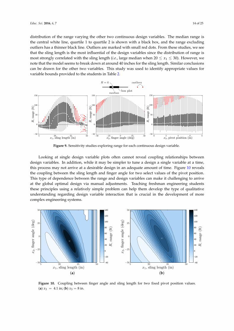
Appropriate ranges for continuous design variables (defined by upper and lower bounds) wereidentified using the multibody dynamic model. Each of the continuous design variables was variedover a large range of values. This study is shown in Figure 9; individual box plots show the
Educ. Sci. 2016, 6, 7 14 of 25
distribution of the range varying the other two continuous design variables. The median range isthe central white line, quartile 1 to quartile 2 is shown with a black box, and the range excludingoutliers has a thinner black line. Outliers are marked with small red dots. From these studies, we seethat the sling length is the most influential of the design variables since the distribution of range ismost strongly correlated with the sling length (i.e., large median when 20 ≤ x1 ≤ 30). However, wenote that the model seems to break down at around 40 inches for the sling length. Similar conclusionscan be drawn for the other two variables. This study was used to identify appropriate values forvariable bounds provided to the students in Table 2.
x1 ,
sling
length
(in)
R, range (ft)!50 0 50
100
150
520
3550
R = 0
median
outliers
box plot
x1, sling length (in)
R,ra
nge
(ft)
!50
0
50
100
150
5 20 35 50x2, -nger angle (deg)
R,ra
nge
(ft)
!50
0
50
100
150
!50 !25 0 25 50x3, pivot position (in)
R,ra
nge
(ft)
!50
0
50
100
150
0 2 4 6 8
Figure 9. Sensitivity studies exploring range for each continuous design variable.
Looking at single design variable plots often cannot reveal coupling relationships betweendesign variables. In addition, while it may be simpler to tune a design a single variable at a time,this process may not arrive at a desirable design in an adequate amount of time. Figure 10 revealsthe coupling between the sling length and finger angle for two select values of the pivot position.This type of dependence between the range and design variables can make it challenging to arriveat the global optimal design via manual adjustments. Teaching freshman engineering studentsthese principles using a relatively simple problem can help them develop the type of qualitativeunderstanding regarding design variable interaction that is crucial in the development of morecomplex engineering systems.
−50
−25
0
25
50
5 20 35 50
x1, sling length (in)
x2,finger
angle
(deg)
R,range
(ft)
−40
−20
0
20
40
60
80
100
120
140
(a)
−50
−25
0
25
50
5 20 35 50
x1, sling length (in)
x2,finger
angle
(deg)
R,range
(ft)
−40
−20
0
20
40
60
80
100
120
140
(b)
Figure 10. Coupling between finger angle and sling length for two fixed pivot position values.(a) x3 = 4.1 in; (b) x3 = 8 in.
Educ. Sci. 2016, 6, 7 15 of 25
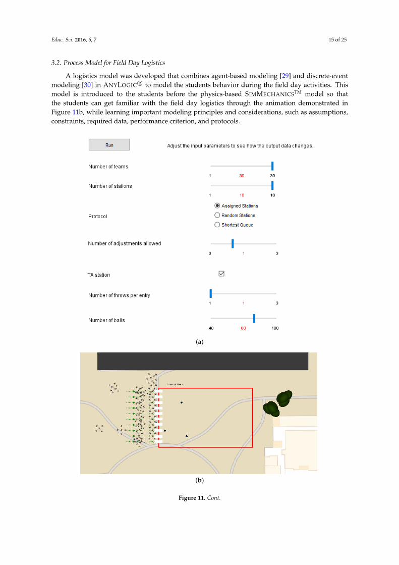
3.2. Process Model for Field Day Logistics
A logistics model was developed that combines agent-based modeling [29] and discrete-eventmodeling [30] in ANYLOGIC R© to model the students behavior during the field day activities. Thismodel is introduced to the students before the physics-based SIMMECHANICSTM model so thatthe students can get familiar with the field day logistics through the animation demonstrated inFigure 11b, while learning important modeling principles and considerations, such as assumptions,constraints, required data, performance criterion, and protocols.
(a)
(b)
Figure 11. Cont.

Educ. Sci. 2016, 6, 7 16 of 25
(c)
Figure 11. Field day logistics model built with ANYLOGIC R©. (a) parameter page; (b) screenshot oflive animation of the field day logistics model; (c) simulation output page.
Agent-based modeling techniques are used to approximate the movement of students throughthe launch and staging areas during testing activities. Space limitations constrain the number ofstudent groups that can launch trebuchet projectiles at a time, so many student groups must wait fortheir turn to test. A discrete-event modeling framework was used to simulate movement throughlaunch queues. Queues fill up based on how the teams decide to join, directions from staff, and otherfactors. Three different protocols were considered for how the agents (student groups) would interactas they form queue at the launch pads:
• Assigned stations — Each team is assigned a station and they rotate with other teams assignedto the same station;
• Random stations — Teams join a random queue without any thought;• Shortest queue — When teams are ready, they join a station with the shortest line.
Some other tunable parameters included the number of adjustments allowed on the launch padand the number of throws per entry (see Figure 11a for the complete list of tunable parameters).Additional constraints considered include the number of throwing stations (i.e., queues, limited dueto space constraints), the total amount of class time (50 min), and the limited number of projectiles.When all available projectiles have been launched, the the instructor halts launches and course staffretrieve the projectiles from the field. Some of these constraints were also made tunable so thestudents could observe their effect on simulation results. A number of different performance criterionavailable for the students to consider including total number of throws, number of throws for theslowest team, and the number of teams with throws below a certain threshold. Students soughta launch policy that increased the total number of projectile launches, while also striving to fairlydistribute tests among project groups.
A large number of parameter values were needed to fully realize an accurate representation ofthe ANYLOGIC R© model. Model parameter estimation was performed using data obtained during amock launch day conducted by student volunteers not in the class. Model parameters were estimatedfrom physical tests such as time to adjust specific trebuchet design variables, total time to launch theprojectile when on the throwing station, projectile retrieval time for a given number of projectiles andcourse staff members, and walking speed of the student groups with the trebuchets (which can bedetermined from the simulation output page in Figure 11c). Under the conditions during fall 2014,it is seen that the assigned station protocol results in the largest total number of throws but with
Educ. Sci. 2016, 6, 7 17 of 25
moderate variability in the distribution of throws between groups. The shortest queue had a slightlysmaller total number of throws but more uniformity between the groups. The random queue wassubstantially worse than the other two.
4. Student Improvements in Trebuchet Comprehension and Engineering Judgment
In this section, we provide some results that highlight students’ improvement in trebuchet designcomprehension and engineering judgment throughout the course stages. These results are importantelements of the mixed-method (triangulation) approach used to determine whether this project-basedcurriculum was effective at achieving the learning objectives [34,37]. To that end, we begin with somerelevant background information pertaining to the collected data.
4.1. Setup
4.1.1. Participants
The launch data analyzed in this section was obtained from a large group of freshmenengineering students (109 students were enrolled in fall 2014, which is the semester this data wasobtained from). The students were divided into four or five member groups resulting in 23 totalgroups. The facilitators of the course, lab, and launch days consisted of the professor teaching thecourse, a graduate student TA, and a number of undergraduate and graduate student assistantscontributing during modeling labs and launch days.
4.1.2. Instruments and Design—Four Course Activities
The data consists of the information obtained from four course assignments—a DOE activity,model-based design activity (see Section 3.1), and two field day trebuchet launches with physicalexperiments. The activities were completed in the following order:
DOE −→ field day #1 −→ computer modeling lab −→ field day #2
The DOE exercise consisted of several tasks that culminated in the construction of an experimentplan for the first field day. Task 1 required students to rank the design variables according to perceivedinfluence on projectile range. Task 2 encouraged students to physically adjust all design variables toget an intuitive feel for the trebuchet design and identify the realistic variable bounds. Task 3 requiredstudents to practice adjusting the physical components of the trebuchet in a time-efficient manner.The final task, task 4, required students to strategically decide on eight sets of design variables theybelieved would provide insights and that would lead to a design with maximum launch distance.
During field day #1, the students were tasked with performing a total of eight physical launchesusing the planned tests from the previous DOE exercise. Throughout the exercise, students madeadjustments to the trebuchet settings to explore effects on projectile launch distance. Launchdistances were self-reported based on visually determining the distance relative to equally-spaced10 ft markers. Because certain groups required more time to reconfigure trebuchet settings betweenlaunches, not every group completed the eight allotted launches. The total number of launches forfield day #1 was 138.
After field day #1 and a lecture on trebuchet physics and simulation, the model-based designlab activity helped students experience the value of physics-based modeling and simulation in thedesign process. Since the students had already completed a few physical experiments with thetrebuchet on field day #1, they were able to appreciate the ability to test many more designs ina short time span using a physics-based computer model. Students were instructed in computermodel use, including how to input different design variable values into the trebuchet model and howto run the simulation to obtain the predicted projectile trajectory and launch distance. The modelalso included sophisticated animation capabilities that helped the students visualize how exactly the
Educ. Sci. 2016, 6, 7 18 of 25
trebuchet moved for each candidate design. Students could move forward and backward in timewith these animations with precise control to examine trebuchet dynamics very accurately. In thecourse of these studies students sought a design with maximum projectile range. During this process,they also developed deeper intuition for design tradeoffs and dynamic behavior than was obtainedduring earlier project activities. Based on this model-based design exploration activity, studentgroups were asked again to predict the relative importance of the design variables with respect toimproving projectile range. At the end of the exercise, students used the model interface to createan automatically generated report that presented a summary of tested designs. A second experimentplan was constructed for use during field day #2. This plan was distinct from the first experimentplan in that designs were clustered around the predicted best design. Both the experiment plan andthe model-based design exploration report were submitted to the instructor and were provided forstudents to use during the second field day tests.
During field day #2, students remained in their same respective groups as the first field day.Each group was allotted two rounds of eight launches. Most groups performed their 16 launches,but there were some that could not or chose not to finish all the launches. Unlike the first field day,the students were strongly encouraged to explore “on the fly” different values of the design variablesto achieve the best range possible, learning from each physical experiment. The total number oflaunches for the second field day was 180, 42 more than the first field day.
4.2. Results and Discussion
4.2.1. Design Variable Rankings
Table 3 shows the student and instructor rankings of the design variables. The rankings forstudents (shown in DOE activity and MBD activity) is fractional since its averaged over all the studentgroups. The student rankings of design variables in the DOE activity case is completely basedon intuition, where-in they assign highest importance to pivot position (score 1.8). After studentscomplete the day 1 launches and model-based design (MBD) activity they on average identify that thefinger angle is most important design variable (score 1.8). Lastly, the instructor’s ranking of designvariables is based on results of comprehensive computer simulations, shown in Figures 9 and 10.These results suggest that the combination of experiments during field day #1 and the model-baseddesign activity improved the students’ intuition of the trebuchet design variables and is a directquantitative measure of the learning outcomes [34].
Table 3. Student and instructor rankings of the design variables.
Variable DOE Activity MBD Activity Instructor
Sling Length 2.3 2.2 1Finger Angle 2.0 1.8 2Pivot Position 1.8 3.4 4
Wheels 3.9 2.5 3
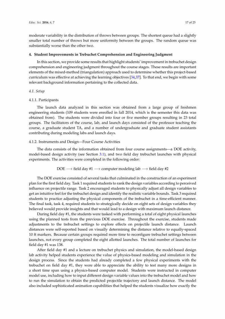
4.2.2. Statistical Analysis of Field Day Launch Distances
Descriptive statistics were used to build a profile for the two field day launch experiments.A summary of that profile is presented in Table 4. The statistics show that the mean launchdistances for day 2 was 15.65 feet longer than that of day 1, and that the standard deviation of thelaunch distances for launch day 2 was 3.76 feet smaller than day 1. Figure 12 shows the differencebetween the launch distances between days providing a performance overview for both days. It alsoillustrates how day 2 launches were longer and less sporadic, however there were some outliers. Itcan be inferred that students were correctly adjusting the trebuchet variables to maximize launchdistances. It is therefore hypothesized that the students’ improvements of launch distance on day2 were due to student’s increased knowledge of the complete trebuchet system learned through the
Educ. Sci. 2016, 6, 7 19 of 25
previous activities. A more appropriate experimental design to test the above hypothesis would beto randomize the sequence the students perform the first three activities (DOE, field day #1, andcomputer modeling lab) and to test the above hypothesis related to the effect of the activities.
Field Day
R,ra
nge
(ft)
!40
0
40
80
120
1 2
outliers
Figure 12. Boxplots for launch distances for both field day #1 and field day #2.
The maximum launch distance for day 1 was 114 feet and it was performed by group 15 onlaunch #2. The maximum launch distance for day 2 was 116 feet and it was performed by group 15on launch #6. Out of the total launches for both days, 77% of the maximum distances launched werelaunched on day 2. Fifty-two percent of day 1 launches traveled 90 feet or greater in comparison to83% of day 2. The most repeated launch distance was 80 feet which had 12 occurrences on day 1 and17 occurrences on day 2.
A before and after scenario was staged to determine if the project-based curriculum supportedstudents’ engineering judgment. The experiment tests the influence a physics-based trebuchet modelalong with a computer simulated trebuchet launching activity has on launch distances.
• µ1: field day #1 launch distance (before model-based design activity);• µ2: field day #2 launch distance (after model-based design activity and field day #1);• H0 : µ1 = µ2; There is no difference between mean launch distances of day 1 and day 2;• Ha : µ1 6= µ2; There is a difference between mean launch distances of day 1 and day 2.
A paired sample t-test was used to test the hypothesis. The analyses indicated there was astatistically significant difference between the mean launch distances of day 1 and day 2; p < 0.05.Table 4 details the full results. With the knowledge that the mean of the two launch day distanceswere significantly different, the H0 can be rejected and the Ha is accepted. Since the earlier descriptivestatistics data (in Table 4) showed day 2 having a greater mean launch distance, it can be concludedthat there were statistically significantly greater distances launched on day 2.
Table 4. Statistical analysis of the difference between field day #1 and #2 launch distances.
Quantity x̄ σ SEx̄ 95% CI T D f
∆Range (day 1 - day 2) 15.652 38.745 3.298 (9.130, 22.174) 4.746 137
The between day findings suggest that students were better equipped for the second field daylaunches. On the first field day, students relied heavily on nascent intuition to predict successfultrebuchet design variable values using a space-filling strategy. The launches performed by studentson second field day were heavily influenced by the preferred solutions they obtained throughthe simulation-based design exploration exercises. Although the individual student experiences

Educ. Sci. 2016, 6, 7 20 of 25
were not reported, the data clearly showed some benefit of targeted experience with engineeringanalysis and simulation-based exploration on engineering judgment through improved launchdistance performance. Analysis of student essays, combined with quantitative data, strengthensevidence that this pedagogical strategy does have an impact on the ability of students to integrateanalytical engineering knowledge with practical design tasks to improve engineering decisionmaking. Students were largely able to develop an understanding of how physical experimentsdiffered from model results, especially after a larger number of test launches on the second field day.
It should be cautioned, however, that the study does not attribute these findings only to themodel-based design because the analysis did not take into account other possible factors such asfamiliarity with the trebuchets due to field day #1 or ambient weather conditions.
The marginal means of the launch distance between the days for each group is shown inFigure 13. Group #6 and #19 representing low and high mean ranges respectively. Since the study wasmost concerned with improved range, the trebuchet design for group #19 perhaps could serve as animportant reference point for maximum distance. We also see that 20 of the 23 groups (87%) havinggreater mean distances on day 2. However, to determine whether this meant there was a significantdifference between groups, a univariate analysis was applied (see Table 5 for a summary of thisanalysis). The analysis found that there were statistically significant differences in launch distancesbetween groups, between days, and between groups and days combined. Therefore, even thougheach group was unique, their progress between days favored longer launches. This is importantbecause it signals that some groups outperformed other groups. What should be investigated is howwell students in the different groups understood the various physics, mathematics, and engineeringconcepts involved in the activity, and whether these differences in understanding correlate withtrebuchet design performance. The two-sample t-test that was performed in the study did not identifywhich groups had significantly lower launch distances than other groups. These groups can beidentified by using an ad hoc test or by comparing trebuchet variable data with the optimizationvariable ranking model.
20
40
60
80
100
1 2 3 4 5 6 7 8 9 10 11 12 13 14 15 16 17 18 19 20 21 22 23
Group
R,range(ft)
Day 1Day 2
Figure 13. Marginal means of distance between the field days for each group.

Educ. Sci. 2016, 6, 7 21 of 25
Table 5. Univariate analysis on dependent variable launch distance.
Source Type III Sum Sq. D f Mean Square F p
Corrected Model 90972a 45 2022 3.2 0Intercept 1152161 1 1152161 1827.0 0
Group 40067 22 1821 2.9 0Day 25845 1 25845 41.0 0
Group × Day 23328 22 1060 1.7 0.031
Error 171530 272 631Total 1537276 318
Corrected Total 262503 317a : R2 = 0.347, R2
adj = 0.238 .
4.2.3. Qualitative Assessment of Student Reflections on Mathematical and Scientific Tools inEngineering Practice
At the end of the course, the students were required to answer a few questions in short essayformat. One of the required questions was:
How do mathematical and scientific tools, such as mathematical modeling and simulation, play animportant role in engineering practice?
Understanding the role of mathematical and scientific tools in engineering practice is arequirement for good engineering judgment. Therefore the essay responses were qualitativelystudied to see the student’s final thoughts on this concept.
After reviewing student responses, several themes surfaced. Intuition building, processimprovements, prototyping, and optimization were all described as uses of the mathematical andscientific tools in the engineering design process. Many expressed that their current and futurecourses may primarily focus on building their technical knowledge but most practical engineeringchallenges require the application of this technical knowledge. Some students acknowledged thattheir fundamental engineering courses will form a basis for their engineering intuition and will teachthem the quantitative tools required to solve complex engineering problems. All of these responsesare aligned with good engineering judgment. This assessment was direct qualitative measure of thelearning outcomes [34].
4.2.4. Students vs. Optimization Algorithm
Students reported each test that they performed during the model-based design activity.Their test numbers were then compared to the tests performed by two common optimizationalgorithms to compare their search procedure and performance. The first optimization algorithmwas gradient-based, namely fmincon in MATLAB R© [35]. The other algorithm was gradient-free,namely patternsearch in MATLAB R© [36]. Each data point in this comparison represents a distinctfunction call, i.e., a single execution of the trebuchet simulation (whether by student or optimizationalgorithm) for a unique trebuchet design. Optimization algorithm tolerances were loosened to allowfaster termination, producing results that were better aligned with the number of tests performed bythe students.
The first three designs tested by students were provided by the instructor so that students couldgain some experience with the simulation process. The initial design was near the global minimumfor range (see Figure 10); this corresponds to a very low-performance design. This low-performancedesign was used as the starting point for the optimization algorithms. In addition, the students werefree to change the discrete wheels variable, while the optimization algorithm always had wheels onin the design (including wheels increases performance). Figure 14 compares the values at each testfor the range and three continuous design variables. The two optimization algorithms are comparedagainst three representative student project groups.

Educ. Sci. 2016, 6, 7 22 of 25
Version December 22, 2015 submitted to Education 25 of 30
−20
30
80
130R
(ft)
Group A
5
20
35
50
x1(in)
−50
0
50
x2(deg)
0
4
8
x3(in)
10 20 30 40 50 60test number
Group B
10 20 30 40 50 60test number
Group C
10 20 30 40 50 60test number
0 10 20 30 40 50 60 70−40
−20
0
20
40
60
80
100
120
140
160
student gradient-based gradient-free
Figure 14. Student tests with computational model compared with optimization algorithms(both gradient-based and gradient-free).
Figure 14. Student tests with computational model compared with optimization algorithms (bothgradient-based and gradient-free).
We first note that all groups eventually achieve a design near 130 ft (global optimum is 149 ft)even from a starting point that had a very poor range of −32 ft. Group A seems to understandthe trebuchet design immediately with increasing range with every test until arriving near theirbest design very quickly. Group B had range progress similar to the gradient-based method, withconsistently increasing range but with some lower values as well. The Group C test sequence wasmore chaotic, but still produced a general increase in range. The overall theme between the groups istheir ability to greatly outperform the gradient-based methods with a lower number of tests and beon par with the gradient-free approach. This may be due to the students ability to use engineeringintuition for physical systems in combination with quantitative analysis (i.e., engineering judgment),as opposed to being limited to quantitative understanding only (as is the case with the optimizationalgorithms). Optimization algorithms ultimately find better performing designs. It seems that, whenstudent groups find a design that performs reasonably well, their design improvement stagnates.
These results may be explained by the approach the students use to explore the design space,namely, it is observed from the data that student groups tend to tune a single variable at a time [17].This is in contrast to the process used by optimization algorithms, which can move in non-orthogonalsearch directions. Even though optimization algorithms may require more simulation executionsthan a human-in-the-loop approach, they eventually arrive near the global optimum. When variablecoupling is present (as is evidenced in Figure 10), convergence is often slow when using the strategy

Educ. Sci. 2016, 6, 7 23 of 25
of tuning a single variable at a time. Another factor here is that student groups were each giventhe same set of three sample designs to test initially. While the first design produced minimumrange, the others were reasonable designs, and provided a good starting point for design exploration.Other starting points may have kept the students in the negative range for many of the tests (whichexplains why a reasonable guess was given). Further studies into this behavior may produce insightsinto how students think about design early in their engineering education and pave the way foreducation models that teach students how to combine human design intuition with quantitative tools(such as simulation and algorithmic optimization) to arrive at superior designs quickly. An importantrelated topic is the influence that different types of hands-on and simulation-based design explorationactivities has on enhancing design intuition.
5. Conclusions
The objective of the study presented here was to investigate how well a project-based curriculum:(1) helps first-year engineering students gain firsthand experience with the value of engineeringanalysis and mathematical models in practical engineering design; and (2) supports students indeveloping engineering judgment. A sequence of activities (both active and lecture forms) werecreated with these objectives in mind.
A mixed-methods (triangulation) approach was used to determine whether this project-basedcurriculum was effective at achieving the learning objectives [34,37]. A combination of direct/indirectand quantitative/qualitative measures were analyzed. Discussion of the improved design variableranks (Section 4.2.1), improved launch distance measurements throughout the stages (Section 4.2.2),short essay responses aligned with learning objectives (Section 4.2.3), nonrandom input decisionsmade to the simulation model (Section 4.2.4), and successful completion of the written assignments(DOE activity and model-based design activity) complemented and converge towards the conclusionthat the curriculum, to some degree, addressed the learning objectives.
The data also showed students making adjustments to the trebuchet variables that increasedlaunch distances, even if these designs were notably different from the designs predicted asoptimal using the model. This highlights the ability of students to combine knowledge gainedthrough hands-on experience with quantitative investigations to strengthen engineering judgmentand arrive as superior design solutions quickly. This insight paves the way for development ofpromising education models that teach students how to combine human design intuition withquantitative tools (such as simulation and algorithmic optimization) to design systems with superiorperformance. A more structured and comprehensive study in this area could lead to noveleducational methods for improving engineering judgment of engineers at all experience levels.Additional assessment techniques not utilized in this study such as think-aloud protocols andpre/post evaluations could lead to novel insights that support successful development of theseeducational methods. Longitudinal studies could be conducted to understand how activitiesdesigned to improve engineering judgment early in the student’s academic journey affect theirpreparedness and final outlook on the engineering discipline. This research area is identified asfuture work.
Supplementary Materials: The following supplemental materials are made available online at http://systemdesign.illinois.edu/projects/trebuchets.php:
1. SIMMECHANICSTM model described in Section 3.1;2. ANYLOGIC R© model described in Section 3.2;3. Manufacturing instructions;4. Assembly instructions;5. Launch day instructions given to the students to help them understand the logistics and safety of the
launch day;6. DOE activity assignment;7. Model-based design activity assignment;8. CAD files of the various trebuchet parts;9. Short video of the events.
Educ. Sci. 2016, 6, 7 24 of 25
Acknowledgments: The authors would like to acknowledge the efforts of many individuals who assistedwith the development of the trebuchet kits, creation of curricular materials, and with managing the courseproject. Jason McDonald, Danny Lohan, Nick Farace, Allen Kaitharath, Tinghao Guo, Jeff Arena, Adam Cornell,and Lakshmi Gururaja Rao all made significant contributions. Several other graduate and undergraduatestudents at the University of Illinois at Urbana-Champaign (UIUC) beyond those listed above also madecontributions. Several undergraduate research assistants were supported by the Department of Industrial andEnterprise Systems Engineering (ISE) at UIUC to make important improvements to trebuchet kits, create andtest multi-agent models, and to make other direct contributions. Support for fabrication of the trebuchet kitswas provided by both the ISE department and the College of Engineering at UIUC. MathWorks, Inc. providedsupport through a curriculum innovation award, including software licenses and specialized technical support.
Author Contributions: James Allison conceived the idea for this project, developed the curriculum, ledthe fabrication of reconfigurable kits and administered class as a lead instructor. Anand Deshmukh andDaniel Herber (and other graduate students) developed the interactive computers models. Anand Deshmukhand Daniel Herber (and other students) supported the fabrication of the trebuchet kits and helped conduct thefield launches. Daniel Herber and Marlon Mitchell provided the data analysis in the paper. All authors equallycontributed to literature review and writing of the paper.
Conflicts of Interest: The authors declare no conflict of interest.
References
1. What is Project Based Learning (PBL)? Available online: http://bie.org/about/what_pbl (accessed on 20February 2016).
2. Solomon, G. Project Based Learning: The Primer. Tech Learn. Mag. 2003, 23, 20–26.3. Pilot, A.; Bulte, A.M.W. The use of “contexts” as a challenge for the chemistry curriculum: Its successes &
the need for further development and understanding. Int. J. Sci. Educ. 2006, 28, 1084–1112.4. Mills, J.E.; Freagust, D. Engineering education—Is problem-based or project-based learning the answer?
Australas. J. Eng. Educ. 2003, 3, 1–16.5. National Science Foundation. Systemic Engineering Education Reform: An Action Agenda; Technical Report;
National Science Foundation: Arlington, VA, USA, 1997.6. Tempelman, E.; Pilot, A. Strengthening the link between theory and practice in teaching design engineering:
An empirical study on a new approach. Int. J. Technol. Des. Educ. 2011, 21, 261–275.7. Savage, R.N.; Chen, K.C.; Vanasupa, L. Integrating project-based learning throughout the undergraduate
engineering curriculum. J. STEM Educ. 2007, 8, 15–27.8. Dym, C.L.; Agogino, A.M.; Eris, O.; Frey, D.D.; Leifer, L.J. Engineering design thinking, teaching, and
learning. J. Eng. Educ. 2005, 94, 103–120.9. Hadim, H.A.; Esche, S.K. Enhancing the engineering curriculum through project-based learning.
In Proceedings of the 32nd Annual Frontiers in Education, Boston, MA, USA, 6–9 November 2002; Volume 2.10. Silk, E.M.; Schunn, C.D.; Cary, M.S. The impact of an engineering design curriculum on science reasoning
in an urban setting. J. Sci. Educ. Technol. 2009, 18, 209–223.11. Wallace, K. (Ed.) Educating Engineers in Design; Royal Academy of Engineering: London, UK, 2005.12. Frost, R.B. A converging model of the design process: Analysis and creativity, the ingredients of synthesis.
J. Eng. Des. 1992, 3, 117–126.13. Daly, S.R.; Yilmaz, S.; Christian, J.L.; Seifert, C.M.; Gonzalez, R. Design heuristics in engineering concept
generation. J. Eng. Educ. 2012, 101, 601–629.14. Carberry, A.R.; McKenna, A.F. Exploring student conceptions of modeling and modeling uses in
engineering design. J. Eng. Educ. 2014, 103, 77–91.15. Basili, V.R.; Shull, F.; Lanubile, F. Building knowledge through families of experiments. IEEE Trans. Softw.
Eng. 1999, 25, 456–473.16. Evans, J.R. Engineering Design: Search and Evaluation; Coherence and Correspondence; Intuition and
Analysis. M.S. Thesis, Massachusetts Institute of Technology, Cambridge, MA, USA, 2009.17. Papalambros, P.Y.; Wilde, D.J. Principles of Optimal Design: Modeling and Computation; Cambridge University
Press: Cambridge, UK, 2000.18. Brice, L.L.; Catania, S. A pedagogical trebuchet: A case study in experimental history and history pedagogy.
Hist. Teach. 2012, 46, 67–84.19. Leifer, J. An Active Learning Design Project for a Junior-level Kinematics and Dynamics Class.
In Proceedings of the 32nd Annual Frontiers in Education, Boston, MA, USA, 6–9 November 2002; Volume 1.

Educ. Sci. 2016, 6, 7 25 of 25
20. Jahed, H. Trebuchet Design; ME380 Project Manual; University of Waterloo: Waterloo, ON, Canada, 2006.21. Brannan, K.P.; Murden, J.A.; Stout, R.H., Jr. The Great Trebuchet Project. In Proceedings of the 2002 ASEE
Southeast Section Conference, Gainesville, FL, USA, 7–9 April 2002.22. Leonard, K.M.; Mastromonico, J.J., Jr. Integrating Engineering Design Heuristics into a First Year
Engineering Course to Enhance Problem Solving and Team Building Skills. In Proceedings of the 2007International Conference on Engineering Education, Coimbra, Portugal, 3–7 September 2007.
23. Kenefic, R.; Lin, F.; Aschliman, D. Integrated design and analysis for a trebuchet using a high speedphotographic measurement system and MATLAB. In Proceedings of the 2006 ASEE Illinois-Indiana andNorth Central Joint Section Conference, Fort Wayne, IN, USA, 31 March–1 April 2006.
24. Slater, J. Making math and science exciting through engineering sport: The wright state university trebuchetcompetition. In Proceedings of the 2008 ASEE Annual Conference and Exposition, Pittsburgh, PA, USA,22–25 June 2008; Number AC 2008-2221.
25. Constans, E.; Constans, A. Treb-bot: Development and use of a trebuchet simulator. Phys. Teach. 2015, 53,347–348.
26. English, L.D.; Hudson, P.; Dawes, L. Engineering-based problem solving in the middle school: Design andconstruction with simple machines. J. Pre-Coll. Eng. Educ. Res. 2013, 3, doi:10.7771/2157-9288.1081.
27. Allison, J. Trebuchet Range Simulation and Optimization; MATLAB Central: Natick, MA, USA, 2012.28. Forrester, A.; Sobester, A.; Keane, A. Engineering Design via Surrogate Modelling: A Practical Guide; Wiley:
Hoboken, NJ, USA, 2008.29. Bonabeau, E. Agent-based modeling: Methods and techniques for simulating human systems. Proc. Natl.
Acad. Sci. USA 2002, 99, 7280–7287.30. Fishman, G. Discrete-Event Simulation: Modeling, Programming, and Analysis, 1st ed.; Springer Science &
Business Media: Berlin, Germany, 2013; doi:10.1007/978-1-4757-3552-9.31. Thomas, E.W.; Marr, J.; Walker, N. Enhancement of Intuitive Reasoning through Precision Teaching and
Simulations. In Proceedings of the Frontiers in Education Conference, Atlanta, GA, USA, 1–4 November1995; Volume 2.
32. Siano, D.B. Trebuchet Mechanics. Available online: http://www.algobeautytreb.com/trebmath356.pdf(accessed on 20 February 2016).
33. Goebel, R.; Sanfelice, R.G.; Teel, A. Hybrid Dynamical Systems. IEEE Control Syst. 2009, 29, 28–93.34. Breslow, L. Methods of Measuring Learning Outcomes and Value Added; Online Report; Teaching and Learning
Laboratory: Cambridge, MA, USA, 2007.35. fmincon: version R2014a; The MathWorks, Inc.: Natick, MA, USA. Available online:
http://www.mathworks.com/help/optim/ug/fmincon.html (accessed on 20 February 2016).36. patternsearch: version R2014a; The MathWorks, Inc.: Natick, MA, USA. Available online:
http://www.mathworks.com/help/gads/patternsearch.html (accessed on 20 February 2016).37. Mathison, S. Why Triangulate? Educ. Res. 1988, 17, 13–17.
c© 2016 by the authors; licensee MDPI, Basel, Switzerland. This article is an openaccess article distributed under the terms and conditions of the Creative Commons byAttribution (CC-BY) license (http://creativecommons.org/licenses/by/4.0/).


![MANUFACTURABILITY CONSTRAINT FORMULATION FOR DESIGN …systemdesign.illinois.edu/publications/Patterson2018b.pdf · to re-design the product or system from conception [5,8]. One established](https://static.fdocuments.in/doc/165x107/5e867d92b392c82caa4664ca/manufacturability-constraint-formulation-for-design-to-re-design-the-product-or.jpg)