Design Iterations for Passive Aerial Manipulator
6
Design Iterations for Passive Aerial Manipulator Vidyadhara B. V. 1 , Lima Agnel Tony 1 , Mohitvishnu S. Gadde 1 , Shuvrangshu Jana 1 , Varun V. P. 2 , Aashay Anil Bhise 1 , Suresh Sundaram 3 , Debasish Ghose 1 Abstract— Grabbing a maneuvering target using drones is a challenging problem. This paper presents the design, develop- ment, and prototyping of a novel aerial manipulator for target interception. It is a single Degree of Freedom (DoF) manipulator with passive basket-type end-effector. The proposed design is energy efficient, light weight and suitable for aerial grabbing applications. The detailed design of the proposed manipulation mechanism and a novel in-flight extending propeller guard, is reported in this paper. I. I NTRODUCTION Robotic arms on drones could automate a variety of mundane and tedious tasks performed in less reachable and dangerous settings. Few of these include facade maintenance of buildings, communication tower inspection and repair, fire fighting, load transport, etc. In each of these applications, the design of the robotic arm or the manipulator is specific to the problem being addressed. The design of manipulator end-effector is based on the tools that it needs to work with to execute the desired task. Irrespective of the requirement, the limitations in the existing technology imposes many constraints on the manipulators like being energy optimal, low weight, etc., to perform the mission properly. Thus, design and development of aerial manipulators require a through consideration in various directions for successful execution of the task. Several works on design of aerial manipulators for varied applications are found in literature. Design of mechanism and electronics involved of a contact inspection manipulator is given in [1]. Dexterous manipulator design for operations like wrenching is given in [2]. Design and analysis of a par- allel manipulators are presented in detail, in [3], [4]. Design of a six DoF manipulator, for bar structure assembly is given in [5]. Design and prototyping of a serial multi-link and compact manipulator is presented in [6]. Design of a five bar mechanism with omni-directional workspace is given in [7]. A survey of aerial manipulator modelling and control is given in [8]. [9] presents an active manipulator design for pick and place operations. Design of manipulation mechanisms *This work is partially supported by IISc and Robert Bosch Center for Cyber Physical Systems, (IISc) and Khalifa University 1 Guidance, Control, and Decision Systems Laboratory (GCDSL), Department of Aerospace Engineering, Indian Institute of Science, Bangalore-12, India. [email protected], [email protected], [email protected], [email protected], [email protected], [email protected] 2 Robert Bosch Center for Cyber Physical Systems, Bangalore-12, India. [email protected] 3 Artificial Intelligence and Robotics Laboratory (ARL), Department of Aerospace Engineering, Indian Institute of Science, Bangalore-12, India. [email protected] for aerial grasping are presented in [10]–[12]. Most of these focuses on the modelling of the final design, and the control of the integrated system. It would be interesting to look into the manipulator design from its idea form to the final prototype, which would bring out the intricate details on its developmental aspects. In this work, we present the design and modelling, from scratch, of an aerial manipulation system for moving target grabbing. The proposed end-effector design is novel and simple passive basket-type manipulator. The final design can be used to detach any moving target, up to 150 g weight and 20 cm in size (diameter), for the dimensions and choice of material of the end-effector prototype. The design and prototyping of a self extending propeller guard is also presented, which ensures drone safety during grabbing. The proposed manipulation mechanism can be employed for many applications from automated fruit picking in large orchards to counter-drone missions in defense applications. The design is energy optimal and could be manufactured easily and cost effectively. Safety is also a major aspect when it comes to the aerial grabbing of moving target. This paper also presents in detail the design and prototyping of an in- flight extending drone guard, which protects the propeller during the grabbing process. The paper is organised as follows: Section II describes the problem statement along with the challenges present in achieving the task. Section III gives the detailed design of the manipulator end-effector, manipulator arm, and safety accessories. Section IV discusses the possible improvements on the final design. Section V concludes the paper. II. MOTIVATION AND CHALLENGES I NVOLVED The problem of moving target grabbing is inspired from challenge 1 of MBZIRC 2020 [13]. The target to be grabbed is a ball which is suspended below another drone moving in some fashion. The ball is attached to the other drone via a flexible rod and the attachment between the ball and the rod is magnetic. The success of mission would involve detachment of the ball from the other drone and depositing it in a box. As mentioned in previous section, this problem in general could cater a wide range of applications. Capturing a maneuvering target requires solution to many interesting challenges. The main challenges involved in the design and develop- ment of the manipulator for this problem, are listed below. i) Proper choice of manipulator location with respect to drone body, considering stability during engagement. arXiv:2102.08306v1 [cs.RO] 16 Feb 2021
Transcript of Design Iterations for Passive Aerial Manipulator
Design Iterations for Passive Aerial Manipulator
Vidyadhara B. V.1, Lima Agnel Tony1, Mohitvishnu S. Gadde1, Shuvrangshu Jana1,Varun V. P.2, Aashay Anil Bhise1, Suresh Sundaram3, Debasish Ghose1
Abstract— Grabbing a maneuvering target using drones is achallenging problem. This paper presents the design, develop-ment, and prototyping of a novel aerial manipulator for targetinterception. It is a single Degree of Freedom (DoF) manipulatorwith passive basket-type end-effector. The proposed design isenergy efficient, light weight and suitable for aerial grabbingapplications. The detailed design of the proposed manipulationmechanism and a novel in-flight extending propeller guard, isreported in this paper.
I. INTRODUCTION
Robotic arms on drones could automate a variety ofmundane and tedious tasks performed in less reachable anddangerous settings. Few of these include facade maintenanceof buildings, communication tower inspection and repair, firefighting, load transport, etc. In each of these applications,the design of the robotic arm or the manipulator is specificto the problem being addressed. The design of manipulatorend-effector is based on the tools that it needs to work withto execute the desired task. Irrespective of the requirement,the limitations in the existing technology imposes manyconstraints on the manipulators like being energy optimal,low weight, etc., to perform the mission properly. Thus,design and development of aerial manipulators require athrough consideration in various directions for successfulexecution of the task.
Several works on design of aerial manipulators for variedapplications are found in literature. Design of mechanismand electronics involved of a contact inspection manipulatoris given in [1]. Dexterous manipulator design for operationslike wrenching is given in [2]. Design and analysis of a par-allel manipulators are presented in detail, in [3], [4]. Designof a six DoF manipulator, for bar structure assembly is givenin [5]. Design and prototyping of a serial multi-link andcompact manipulator is presented in [6]. Design of a five barmechanism with omni-directional workspace is given in [7].A survey of aerial manipulator modelling and control is givenin [8]. [9] presents an active manipulator design for pickand place operations. Design of manipulation mechanisms
*This work is partially supported by IISc and Robert Bosch Center forCyber Physical Systems, (IISc) and Khalifa University
1Guidance, Control, and Decision Systems Laboratory (GCDSL),Department of Aerospace Engineering, Indian Institute of Science,Bangalore-12, India. [email protected],[email protected], [email protected],[email protected], [email protected],[email protected]
2 Robert Bosch Center for Cyber Physical Systems, Bangalore-12, [email protected]
3 Artificial Intelligence and Robotics Laboratory (ARL), Department ofAerospace Engineering, Indian Institute of Science, Bangalore-12, [email protected]
for aerial grasping are presented in [10]–[12]. Most of thesefocuses on the modelling of the final design, and the controlof the integrated system. It would be interesting to lookinto the manipulator design from its idea form to the finalprototype, which would bring out the intricate details on itsdevelopmental aspects.
In this work, we present the design and modelling, fromscratch, of an aerial manipulation system for moving targetgrabbing. The proposed end-effector design is novel andsimple passive basket-type manipulator. The final designcan be used to detach any moving target, up to 150 gweight and 20 cm in size (diameter), for the dimensionsand choice of material of the end-effector prototype. Thedesign and prototyping of a self extending propeller guard isalso presented, which ensures drone safety during grabbing.The proposed manipulation mechanism can be employedfor many applications from automated fruit picking in largeorchards to counter-drone missions in defense applications.The design is energy optimal and could be manufacturedeasily and cost effectively. Safety is also a major aspect whenit comes to the aerial grabbing of moving target. This paperalso presents in detail the design and prototyping of an in-flight extending drone guard, which protects the propellerduring the grabbing process.
The paper is organised as follows: Section II describesthe problem statement along with the challenges present inachieving the task. Section III gives the detailed design ofthe manipulator end-effector, manipulator arm, and safetyaccessories. Section IV discusses the possible improvementson the final design. Section V concludes the paper.
II. MOTIVATION AND CHALLENGES INVOLVED
The problem of moving target grabbing is inspired fromchallenge 1 of MBZIRC 2020 [13]. The target to be grabbedis a ball which is suspended below another drone movingin some fashion. The ball is attached to the other dronevia a flexible rod and the attachment between the ball andthe rod is magnetic. The success of mission would involvedetachment of the ball from the other drone and depositing itin a box. As mentioned in previous section, this problem ingeneral could cater a wide range of applications. Capturinga maneuvering target requires solution to many interestingchallenges.
The main challenges involved in the design and develop-ment of the manipulator for this problem, are listed below.
i) Proper choice of manipulator location with respect todrone body, considering stability during engagement.
arX
iv:2
102.
0830
6v1
[cs
.RO
] 1
6 Fe
b 20
21
ii) Optimal extension of end-effector from drone to reachthe ball, without compromising safety and stability.
iii) Suppress uncontrolled vibrations.iv) Structural strength, to apply desired detachment force
to remove ball.v) Remain within a net volume of 120 cm × 120 cm ×
50 cm during take-off and landing phase, keeping thesize of integrated system bounded.
III. MANIPULATOR DESIGN
The following design iterations are followed to achieve arobust design.
A. End effector
The end effector design requires certain essential capa-bilities like quick response, low weight, optimal power con-sumption, etc. The following designs were tested to develop arobust end effector for the considered ball grabbing problem.
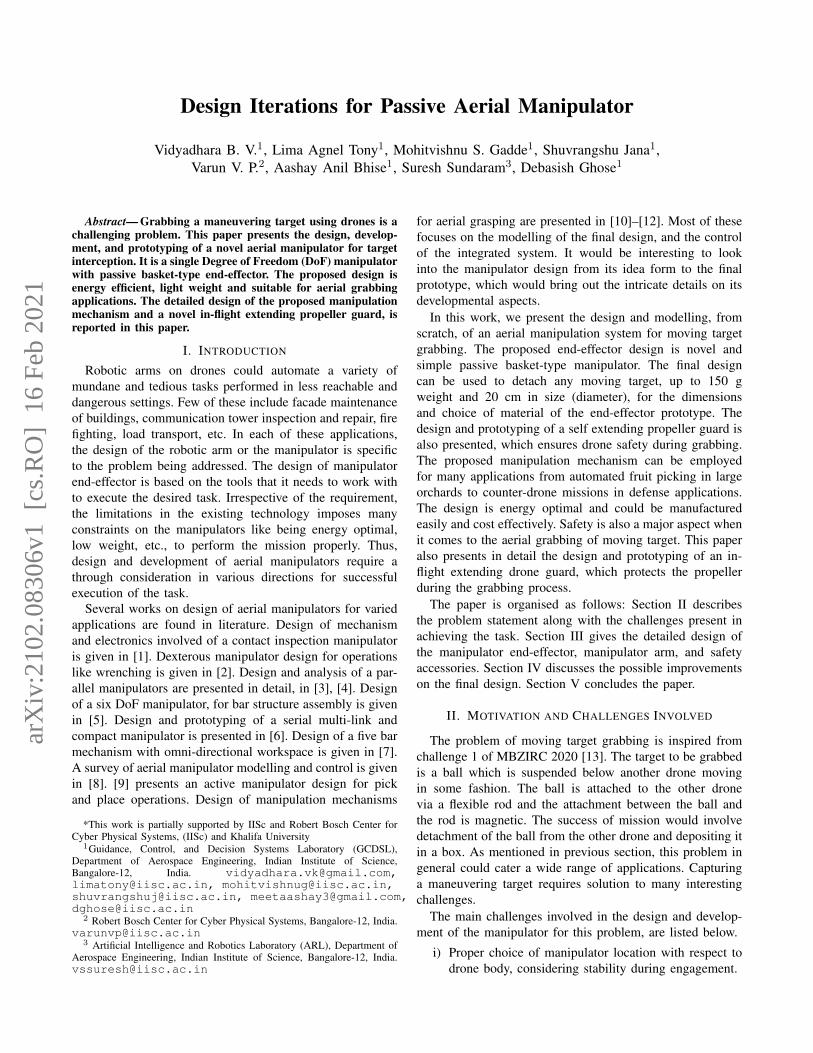
1) Interlocking claws: With careful considerations of thechallenges mentioned in Section II, a suitable manipulatorend-effector was conceived. The primary design was a bio-inspired one, similar to that of how humans would catch aball. The CAD design and its prototype, are shown in Fig.1(a),(b), respectively.
Interlocking claws
(b)(a)
Fig. 1: Active interlocking claw (a) CAD design (b) Proto-type
This design was primarily focused on the requirement ofthe end-effector to be within the size constraints and to beable drop the ball. This proof of concept was to be testedon a smaller drone and hence did not need any actuation.The prototype was fabricated using birch wood. The gripperwas designed with two interlocking claws, which would snapinto a locked position to grasp the ball. The snapping wasactuated by a servo at the joining wrist. To drop the ball, theclaws opened in the downward direction. Initial prototypingand testing showed several deficiencies in conceptualization:the success of grabbing was dependant on the actuationtiming of the servo. The delay posed a problem. Also, theenergy budget had to be analysed thoroughly. Though theenergy consumption for a servo is low, the servo needed to beengaged and disengaged till the ball was grabbed. From thedesign perspective, the end-effector weight had detrimentaleffects on the servo’s functionality: a large sized manipulatorwas not feasible due to its increased weight, which needed alarger servo for higher nominal torque, increasing the energyrequirement. The observations led to the conclusion that an
end-effector of passive nature would be better suited for thejob and multiple DoF are more difficult to handle due to thecomplexity of control and associated delays.
2) Passive basket: The importance of endurance wasunderstood from the initial tests with the active manipulatordiscussed above. Hence, the requirement of using a passiveend-effector with minimal energy usage was incorporatedinto the next iterations.
The redesign of the manipulator was inspired by the fruitpicking mechanism used in orchards, where a metallic wireis used to pluck the fruit which is collected in a net under thewire. The grasping problem could be visualised in a similarway with many added benefits. The mechanism was passiveand thus energy needed was low, provided a larger weightmargin due to absence of servos and additional wiring. Thisgave room for increasing the size of the end-effector. Thedrawback was that, a way to detach the ball was absent,since no interlocking claws were present.
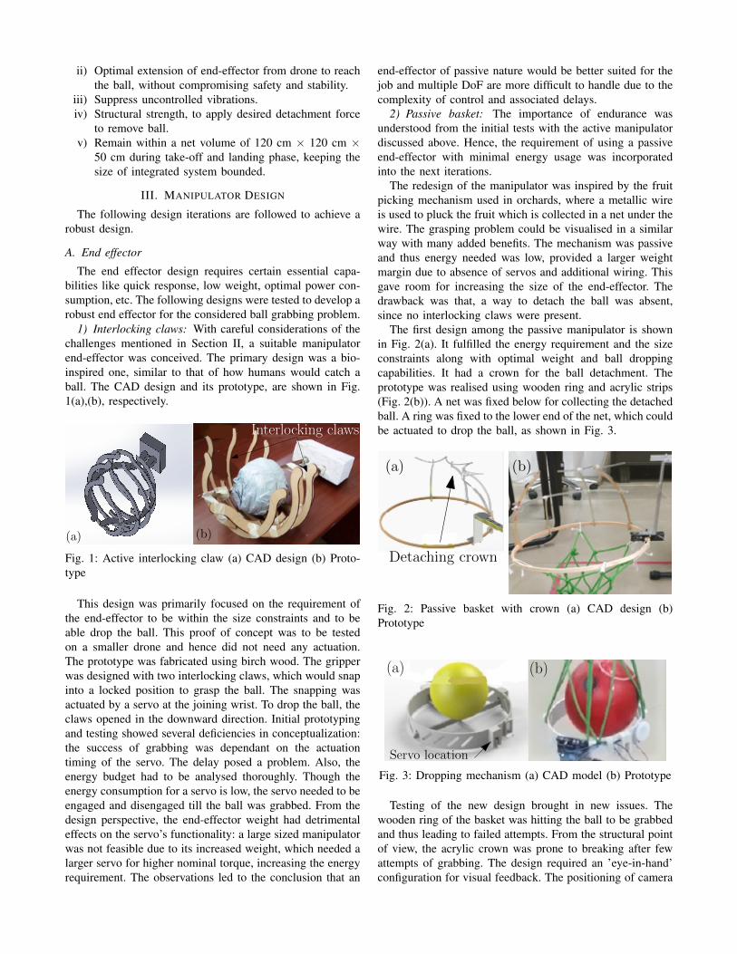
The first design among the passive manipulator is shownin Fig. 2(a). It fulfilled the energy requirement and the sizeconstraints along with optimal weight and ball droppingcapabilities. It had a crown for the ball detachment. Theprototype was realised using wooden ring and acrylic strips(Fig. 2(b)). A net was fixed below for collecting the detachedball. A ring was fixed to the lower end of the net, which couldbe actuated to drop the ball, as shown in Fig. 3.
Detaching crown
(a) (b)
Fig. 2: Passive basket with crown (a) CAD design (b)Prototype
Servo location
(a) (b)
Fig. 3: Dropping mechanism (a) CAD model (b) Prototype
Testing of the new design brought in new issues. Thewooden ring of the basket was hitting the ball to be grabbedand thus leading to failed attempts. From the structural pointof view, the acrylic crown was prone to breaking after fewattempts of grabbing. The design required an ’eye-in-hand’configuration for visual feedback. The positioning of camera
in the crown was also found to be a difficult task withoutrepeated calibrations. All these helped to arrive at a betterdesign, shown in Fig. 4(a). A dedicated mount was erected
Crest
(a) (b)Throat
Fig. 4: Modified passive basket with crest (a) CAD model(b) Prototype
for the camera. Instead of multiple detachment points, thecrown was redesigned to a crest with a throat which acted asthe single detachment point. Anything caught in the grabbingvolume was naturally led to this point due to the relativemotion of the gripper and ball. The set-up was mounted atan elevation from the camera, aiding unobstructed feedback.The prototype is shown in Fig. 4(b). A slight modificationled to the next design where the sagging net in the previousdesign was well supported and kept out of field of view of thecamera (Fig. 5(a),(b)). The experiments showed the need for
(a) (b)
Mesh support
Fig. 5: Modified basket with mesh support (a) CAD design(b) Prototype
larger grab volumes to accommodate errors in detection. Thefinal prototype was designed to fulfil all the requirements ofthe end-effector.
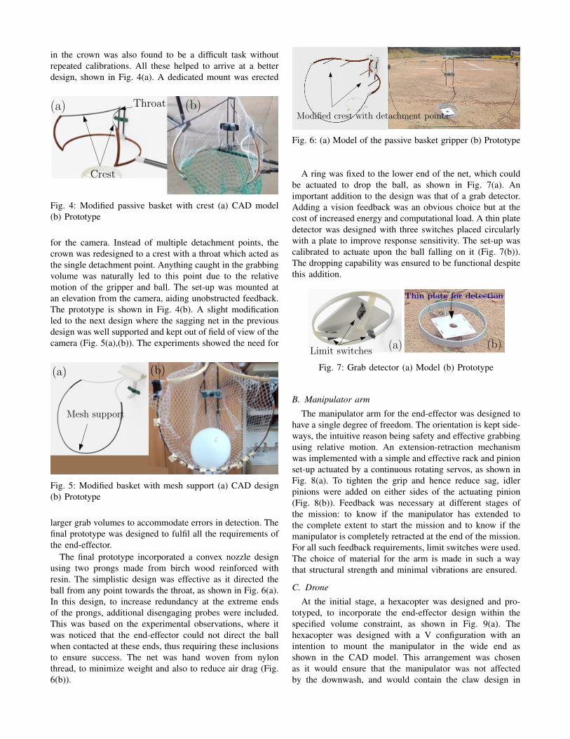
The final prototype incorporated a convex nozzle designusing two prongs made from birch wood reinforced withresin. The simplistic design was effective as it directed theball from any point towards the throat, as shown in Fig. 6(a).In this design, to increase redundancy at the extreme endsof the prongs, additional disengaging probes were included.This was based on the experimental observations, where itwas noticed that the end-effector could not direct the ballwhen contacted at these ends, thus requiring these inclusionsto ensure success. The net was hand woven from nylonthread, to minimize weight and also to reduce air drag (Fig.6(b)).
Modified crest with detachment points
Fig. 6: (a) Model of the passive basket gripper (b) Prototype
A ring was fixed to the lower end of the net, which couldbe actuated to drop the ball, as shown in Fig. 7(a). Animportant addition to the design was that of a grab detector.Adding a vision feedback was an obvious choice but at thecost of increased energy and computational load. A thin platedetector was designed with three switches placed circularlywith a plate to improve response sensitivity. The set-up wascalibrated to actuate upon the ball falling on it (Fig. 7(b)).The dropping capability was ensured to be functional despitethis addition.
Limit switches
Thin plate for detection
(a) (b)
Fig. 7: Grab detector (a) Model (b) Prototype
B. Manipulator arm
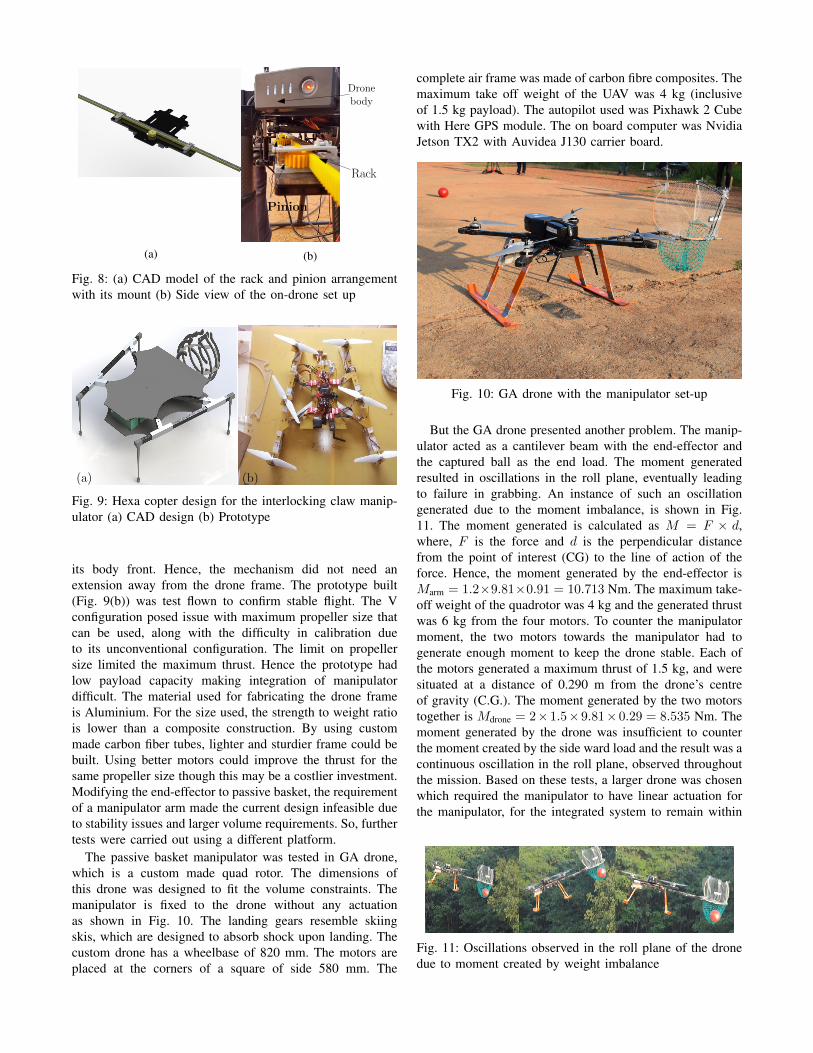
The manipulator arm for the end-effector was designed tohave a single degree of freedom. The orientation is kept side-ways, the intuitive reason being safety and effective grabbingusing relative motion. An extension-retraction mechanismwas implemented with a simple and effective rack and pinionset-up actuated by a continuous rotating servos, as shown inFig. 8(a). To tighten the grip and hence reduce sag, idlerpinions were added on either sides of the actuating pinion(Fig. 8(b)). Feedback was necessary at different stages ofthe mission: to know if the manipulator has extended tothe complete extent to start the mission and to know if themanipulator is completely retracted at the end of the mission.For all such feedback requirements, limit switches were used.The choice of material for the arm is made in such a waythat structural strength and minimal vibrations are ensured.
C. Drone
At the initial stage, a hexacopter was designed and pro-totyped, to incorporate the end-effector design within thespecified volume constraint, as shown in Fig. 9(a). Thehexacopter was designed with a V configuration with anintention to mount the manipulator in the wide end asshown in the CAD model. This arrangement was chosenas it would ensure that the manipulator was not affectedby the downwash, and would contain the claw design in
(a)
Rack
Pinion
Dronebody
(b)
Fig. 8: (a) CAD model of the rack and pinion arrangementwith its mount (b) Side view of the on-drone set up
(a) (b)
Fig. 9: Hexa copter design for the interlocking claw manip-ulator (a) CAD design (b) Prototype
its body front. Hence, the mechanism did not need anextension away from the drone frame. The prototype built(Fig. 9(b)) was test flown to confirm stable flight. The Vconfiguration posed issue with maximum propeller size thatcan be used, along with the difficulty in calibration dueto its unconventional configuration. The limit on propellersize limited the maximum thrust. Hence the prototype hadlow payload capacity making integration of manipulatordifficult. The material used for fabricating the drone frameis Aluminium. For the size used, the strength to weight ratiois lower than a composite construction. By using custommade carbon fiber tubes, lighter and sturdier frame could bebuilt. Using better motors could improve the thrust for thesame propeller size though this may be a costlier investment.Modifying the end-effector to passive basket, the requirementof a manipulator arm made the current design infeasible dueto stability issues and larger volume requirements. So, furthertests were carried out using a different platform.
The passive basket manipulator was tested in GA drone,which is a custom made quad rotor. The dimensions ofthis drone was designed to fit the volume constraints. Themanipulator is fixed to the drone without any actuationas shown in Fig. 10. The landing gears resemble skiingskis, which are designed to absorb shock upon landing. Thecustom drone has a wheelbase of 820 mm. The motors areplaced at the corners of a square of side 580 mm. The
complete air frame was made of carbon fibre composites. Themaximum take off weight of the UAV was 4 kg (inclusiveof 1.5 kg payload). The autopilot used was Pixhawk 2 Cubewith Here GPS module. The on board computer was NvidiaJetson TX2 with Auvidea J130 carrier board.
Fig. 10: GA drone with the manipulator set-up
But the GA drone presented another problem. The manip-ulator acted as a cantilever beam with the end-effector andthe captured ball as the end load. The moment generatedresulted in oscillations in the roll plane, eventually leadingto failure in grabbing. An instance of such an oscillationgenerated due to the moment imbalance, is shown in Fig.11. The moment generated is calculated as M = F × d,where, F is the force and d is the perpendicular distancefrom the point of interest (CG) to the line of action of theforce. Hence, the moment generated by the end-effector isMarm = 1.2×9.81×0.91 = 10.713 Nm. The maximum take-off weight of the quadrotor was 4 kg and the generated thrustwas 6 kg from the four motors. To counter the manipulatormoment, the two motors towards the manipulator had togenerate enough moment to keep the drone stable. Each ofthe motors generated a maximum thrust of 1.5 kg, and weresituated at a distance of 0.290 m from the drone’s centreof gravity (C.G.). The moment generated by the two motorstogether is Mdrone = 2×1.5×9.81×0.29 = 8.535 Nm. Themoment generated by the drone was insufficient to counterthe moment created by the side ward load and the result was acontinuous oscillation in the roll plane, observed throughoutthe mission. Based on these tests, a larger drone was chosenwhich required the manipulator to have linear actuation forthe manipulator, for the integrated system to remain within
Fig. 11: Oscillations observed in the roll plane of the dronedue to moment created by weight imbalance
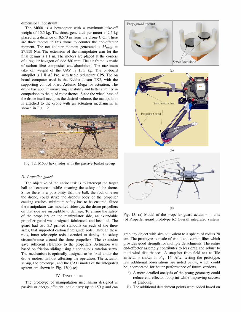
dimensional constraint.The M600 is a hexacopter with a maximum take-off
weight of 15.5 kg. The thrust generated per motor is 2.5 kgplaced at a distance of 0.570 m from the drone C.G.. Thereare three motors in this drone to counter the end-effectormoment. The net counter moment generated is MM600 =27.959 Nm. The extension of the manipulator arm for thefinal design is 1.1 m. The motors are placed at the cornersof a regular hexagon of side 580 mm. The air frame is madeof carbon fibre composites and aluminium. The maximumtake off weight of the UAV is 15.5 kg. The on-boardautopilot is DJI A3 Pro, with triple redundant GPS. The onboard computer used is the Nvidia Jetson TX2, with thesupporting control board Arduino Mega for actuation. Thedrone has good maneuvering capability and better stability incomparison to the quad rotor drones. Since the wheel base ofthe drone itself occupies the desired volume, the manipulatoris attached to the drone with an actuation mechanism, asshown in Fig. 12.
Fig. 12: M600 hexa rotor with the passive basket set-up
D. Propeller guard
The objective of the entire task is to intercept the targetball and capture it while ensuring the safety of the drone.Since there is a possibility that the ball, the rod, or eventhe drone, could strike the drone’s body or the propellercausing crashes, minimum safety has to be ensured. Sincethe manipulator was mounted sideways, the drone propellerson that side are susceptible to damage. To ensure the safetyof the propellers on the manipulator side, an extendablepropeller guard was designed, fabricated, and installed. Theguard had two 3D printed standoffs on each of the threearms, that supported carbon fibre guide rods. Through theserods, inner telescopic rods extended to deploy the safetycircumference around the three propellers. The extensiongave sufficient clearance to the propellers. Actuation wasbased on friction sliding using a continuous rotation servo.The mechanism is optimally designed to be fixed under thedrone motors without affecting the operation. The actuatorset-up, the prototype, and the CAD model of the integratedsystem are shown in Fig. 13(a)-(c).
IV. DISCUSSION
The prototype of manipulation mechanism designed ispassive or energy efficient, could carry up to 150 g and can
Servo locations
Prop-guard mount
(a)
Propeller Guard
Servo mechanism
(b)
(c)
Fig. 13: (a) Model of the propeller guard actuator mounts(b) Propeller guard prototype (c) Overall integrated system
grab any object with size equivalent to a sphere of radius 20cm. The prototype is made of wood and carbon fiber whichprovides good strength for multiple detachments. The entireend-effector assembly contributes to less drag and robust tomild wind disturbances. A snapshot from field test at IIScairfield, is shown in Fig. 14. After testing the prototype,few additional observations are noted below, which couldbe incorporated for better performance of future versions.
i) A more detailed analysis of the prong geometry couldreduce end-effector footprint while improving successof grabbing.
ii) The additional detachment points were added based on
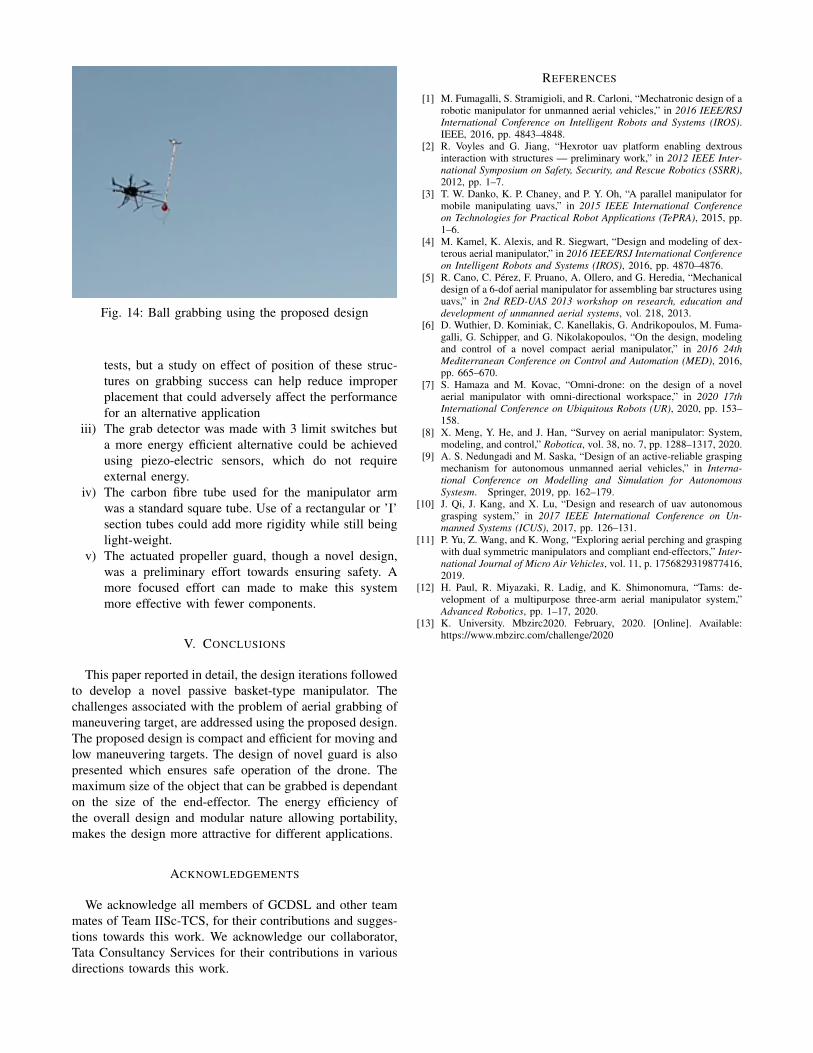
Fig. 14: Ball grabbing using the proposed design
tests, but a study on effect of position of these struc-tures on grabbing success can help reduce improperplacement that could adversely affect the performancefor an alternative application
iii) The grab detector was made with 3 limit switches buta more energy efficient alternative could be achievedusing piezo-electric sensors, which do not requireexternal energy.
iv) The carbon fibre tube used for the manipulator armwas a standard square tube. Use of a rectangular or ’I’section tubes could add more rigidity while still beinglight-weight.
v) The actuated propeller guard, though a novel design,was a preliminary effort towards ensuring safety. Amore focused effort can made to make this systemmore effective with fewer components.
V. CONCLUSIONS
This paper reported in detail, the design iterations followedto develop a novel passive basket-type manipulator. Thechallenges associated with the problem of aerial grabbing ofmaneuvering target, are addressed using the proposed design.The proposed design is compact and efficient for moving andlow maneuvering targets. The design of novel guard is alsopresented which ensures safe operation of the drone. Themaximum size of the object that can be grabbed is dependanton the size of the end-effector. The energy efficiency ofthe overall design and modular nature allowing portability,makes the design more attractive for different applications.
ACKNOWLEDGEMENTS
We acknowledge all members of GCDSL and other teammates of Team IISc-TCS, for their contributions and sugges-tions towards this work. We acknowledge our collaborator,Tata Consultancy Services for their contributions in variousdirections towards this work.
REFERENCES
[1] M. Fumagalli, S. Stramigioli, and R. Carloni, “Mechatronic design of arobotic manipulator for unmanned aerial vehicles,” in 2016 IEEE/RSJInternational Conference on Intelligent Robots and Systems (IROS).IEEE, 2016, pp. 4843–4848.
[2] R. Voyles and G. Jiang, “Hexrotor uav platform enabling dextrousinteraction with structures — preliminary work,” in 2012 IEEE Inter-national Symposium on Safety, Security, and Rescue Robotics (SSRR),2012, pp. 1–7.
[3] T. W. Danko, K. P. Chaney, and P. Y. Oh, “A parallel manipulator formobile manipulating uavs,” in 2015 IEEE International Conferenceon Technologies for Practical Robot Applications (TePRA), 2015, pp.1–6.
[4] M. Kamel, K. Alexis, and R. Siegwart, “Design and modeling of dex-terous aerial manipulator,” in 2016 IEEE/RSJ International Conferenceon Intelligent Robots and Systems (IROS), 2016, pp. 4870–4876.
[5] R. Cano, C. Perez, F. Pruano, A. Ollero, and G. Heredia, “Mechanicaldesign of a 6-dof aerial manipulator for assembling bar structures usinguavs,” in 2nd RED-UAS 2013 workshop on research, education anddevelopment of unmanned aerial systems, vol. 218, 2013.
[6] D. Wuthier, D. Kominiak, C. Kanellakis, G. Andrikopoulos, M. Fuma-galli, G. Schipper, and G. Nikolakopoulos, “On the design, modelingand control of a novel compact aerial manipulator,” in 2016 24thMediterranean Conference on Control and Automation (MED), 2016,pp. 665–670.
[7] S. Hamaza and M. Kovac, “Omni-drone: on the design of a novelaerial manipulator with omni-directional workspace,” in 2020 17thInternational Conference on Ubiquitous Robots (UR), 2020, pp. 153–158.
[8] X. Meng, Y. He, and J. Han, “Survey on aerial manipulator: System,modeling, and control,” Robotica, vol. 38, no. 7, pp. 1288–1317, 2020.
[9] A. S. Nedungadi and M. Saska, “Design of an active-reliable graspingmechanism for autonomous unmanned aerial vehicles,” in Interna-tional Conference on Modelling and Simulation for AutonomousSystesm. Springer, 2019, pp. 162–179.
[10] J. Qi, J. Kang, and X. Lu, “Design and research of uav autonomousgrasping system,” in 2017 IEEE International Conference on Un-manned Systems (ICUS), 2017, pp. 126–131.
[11] P. Yu, Z. Wang, and K. Wong, “Exploring aerial perching and graspingwith dual symmetric manipulators and compliant end-effectors,” Inter-national Journal of Micro Air Vehicles, vol. 11, p. 1756829319877416,2019.
[12] H. Paul, R. Miyazaki, R. Ladig, and K. Shimonomura, “Tams: de-velopment of a multipurpose three-arm aerial manipulator system,”Advanced Robotics, pp. 1–17, 2020.
[13] K. University. Mbzirc2020. February, 2020. [Online]. Available:https://www.mbzirc.com/challenge/2020