
Project acronym: EE-VERT - European Commission · Project acronym: EE-VERT Project ... and...
43
EE-VERT © 2012 The EE-VERT consortium Project acronym: EE-VERT Project title: Energy Efficient VEhicles for Road Transport – EE-VERT Grant Agreement Number: 218598 Programme: Seventh Framework programme, Theme 1.1, Greening Contract type: Collaborative project Start date of project: 1 January 2009 Duration: 36 months Deliverable D3.5.4: D3.5.4: Final report into applicability to and impact on hybrid vehicles Authors: Organisation Name MIRA Alisdair Bowie MIRA Bob Simpkin CRF Carlo D’Ambrosio BOSCH Marcus Abele LEAR Antoni Ferré ECS Leo Rollenitz Reviewers: Organisation Name UPT Ion Boldea FH-J Raul Estrada Vazquez Dissemination level: Public Deliverable type: Report Work Task Number: WT3.5 Version: 1.0 Due date: 31 March 2012 Actual submission date: 18 June 2012 Date of this Version 18 June 2012
Transcript of Project acronym: EE-VERT - European Commission · Project acronym: EE-VERT Project ... and...

EE-VERT
© 2012 The EE-VERT consortium
Project acronym: EE-VERT
Project title: Energy Efficient VEhicles for Road Transport – EE-VERT
Grant Agreement Number: 218598
Programme: Seventh Framework programme, Theme 1.1, Greening
Contract type: Collaborative project
Start date of project: 1 January 2009
Duration: 36 months
Deliverable D3.5.4:
D3.5.4: Final report into applicability to and impact on hybrid vehicles
Authors: Organisation Name
MIRA Alisdair Bowie
MIRA Bob Simpkin
CRF Carlo D’Ambrosio
BOSCH Marcus Abele
LEAR Antoni Ferré
ECS Leo Rollenitz
Reviewers: Organisation Name
UPT Ion Boldea
FH-J Raul Estrada Vazquez
Dissemination level: Public
Deliverable type: Report
Work Task Number: WT3.5
Version: 1.0
Due date: 31 March 2012
Actual submission date: 18 June 2012
Date of this Version 18 June 2012

EE-VERT
© 2012 The EE-VERT consortium
Consortium Members
Organisation Abbreviation Country
MIRA Limited MIRA GB
Volvo Technology AB VTEC SE
Centro Ricerche Fiat Società Consortile per Azioni CRF IT
Robert Bosch GmbH Bosch DE
LEAR Corporation Holding Spain SLU Lear ES
Engineering Center Steyr GmbH & Co KG /
MAGNA Powertrain
ECS AT
FH-JOANNEUM Gesellschaft mbH FH-J AT
Universitatea “Politehnica” din Timisoara UPT RO
SC Beespeed Automatizari SRL BEE RO

EE-VERT Deliverable D3.5.4 18 June 2012
Document history
Version Description Planned
date
Actual
date
0.1 First internal version of deliverable with all contributions 21/05/2012
1.0 First version of deliverable 24/05/2012 18/06/2012
A brief summary
Despite improvements in modern vehicles, a considerable amount of energy is still wasted due to the
lack of an overall on-board energy management strategy. Further electrification of auxiliary systems
promises energy and efficiency gains but there is an additional need for a coordinated approach to the
generation, distribution and use of energy.
The project “EE-VERT” is concerned with improving the energy efficiency of conventional vehicles.
The central concept is the electrification of auxiliary systems, and supplying their energy by recovered
energy from new sources or wasted energy such as recuperation of braking energy, waste heat
recovery or solar cells.
Since hybrid vehicles also use combustion engines and many standard auxiliary systems the project
will also identify the use of EE-VERT smart components and concepts for hybrid applications.
Within WP2 the concepts and solutions for smart components are being developed, which are
necessary for the conversion, storage and distribution of energy with minimised losses. WP2 is also
concerned with the necessary power electronics for the components. The power electronics have to be
studied in EE-VERT since the energy management concepts require novel approaches to overcome
the system integration issues which include optimal electrical power conversion, thermal management
and electromagnetic interference. WP2 is also addressing the link between the EE-VERT approach
and hybrid vehicles. Hybrid vehicles have a high potential to reduce CO2 emissions but they require
cost-intensive and drastic technical modifications. EE-VERT has the objective to improve standard
vehicles by an overall energy management approach using smart components with a moderate
increase in costs. EE-VERT is evaluating several electrically driven auxiliary devices. Since hybrid
vehicles use also many standard components and electrified auxiliaries WP2 will also identify the use
of EE-VERT components for hybrid applications. This will include electrical components and loads
with high energy efficiency, technologies for reuse of thermal energy, predictive algorithms for
energy optimised operation and components or technologies for recuperation of braking energy.
This report firstly discusses the relative positioning of conventional vehicles, the EE-VERT concept
and hybrid vehicles, reviews the types of hybrid vehicles available, the typical components and
functions used. Secondly the EE-VERT approach including energy recovery and the use of optimised
electrified components and its application to hybrid vehicles is discussed. Thirdly the common
characteristics and components of commercially available hybrid and electric vehicles are discussed
and finally the characteristics of the EE-VERT components used for hybrid, electric vehicles are
summarised.

EE-VERT Deliverable D3.5.4 18 June 2012
Version 1.0 Page 2
Contents
A BRIEF SUMMARY .......................................................................................................................... 1
1.1 BACKGROUND ......................................................................................................................... 4
1.2 PURPOSE .................................................................................................................................. 4
1.3 SCOPE ...................................................................................................................................... 5
2 EE-VERT AND HYBRID VEHICLES ....................................................................................... 6
3 TYPES OF HYBRID VEHICLES ............................................................................................... 8
3.1 MICRO HYBRIDS ..................................................................................................................... 8
3.2 MILD HYBRID .......................................................................................................................... 9
3.3 FULL HYBRID: SERIES DRIVETRAIN ........................................................................................ 9
3.4 FULL HYBRID: PARALLEL DRIVETRAIN .................................................................................. 9
3.5 FULL HYBRID: SERIES/PARALLEL DRIVETRAIN ................................................................... 10
3.6 EXAMPLES OF HYBRID AND ELECTRIC VEHICLES ................................................................ 10
3.6.1 Toyota Prius ...................................................................................................................... 10
3.6.2 Chevrolet Volt ................................................................................................................... 11
3.6.3 Nissan Leaf ........................................................................................................................ 12
4 EE-VERT COMPONENTS AND THEIR CHARACTERISTICS ........................................ 12
4.1 MIPEC .................................................................................................................................. 12
4.2 GENERATOR .......................................................................................................................... 14
4.3 LITHIUM ION BATTERY .......................................................................................................... 15
4.4 ELECTRIC AC COMPRESSOR ACTUATOR ............................................................................... 16
4.5 ENGINE COOLING FAN ........................................................................................................... 17
4.6 ELECTRICAL FUEL PUMP ....................................................................................................... 18
4.7 VTG TURBO CHARGER, ELECTRIC ACTUATOR ...................................................................... 19
4.8 VACUUM PUMP ...................................................................................................................... 20
5 COMPONENTS ON COMMERCIAL HYBRID ELECTRIC VEHICLES ......................... 21
5.1 DC/DC CONVERTER AND AUXILIARY BATTERY .................................................................. 22
5.1.1 Toyota Prius ...................................................................................................................... 22
5.1.2 Chevrolet Volt ................................................................................................................... 22
5.1.3 Nissan Leaf ........................................................................................................................ 23
5.2 WATER PUMP ........................................................................................................................ 23
5.2.1 Toyota Prius ...................................................................................................................... 23
5.2.2 Chevrolet Volt ................................................................................................................... 24
5.2.3 Nissan Leaf ........................................................................................................................ 26
5.3 AIR CONDITIONING COMPRESSOR ........................................................................................ 27
5.3.1 Toyota Prius ...................................................................................................................... 27
5.3.2 Chevrolet Volt ................................................................................................................... 28
5.3.3 Nissan Leaf ........................................................................................................................ 29
5.4 OIL PUMP .............................................................................................................................. 29
5.4.1 Toyota Prius ...................................................................................................................... 29
5.4.2 Chevrolet Volt ................................................................................................................... 29
5.4.3 Nissan Leaf ........................................................................................................................ 30
5.5 FUEL PUMP ............................................................................................................................ 30

EE-VERT Deliverable D3.5.4 18 June 2012
Version 1.0 Page 3
5.5.1 Toyota Prius ...................................................................................................................... 30
5.5.2 Chevrolet Volt ................................................................................................................... 30
5.5.3 Nissan Leaf ........................................................................................................................ 30
5.6 POWER STEERING .................................................................................................................. 30
5.6.1 Toyota Prius ...................................................................................................................... 30
5.6.2 Chevrolet Volt ................................................................................................................... 31
5.6.3 Nissan Leaf ........................................................................................................................ 31
5.7 VACUUM PUMP ..................................................................................................................... 32
5.7.1 Toyota Prius ...................................................................................................................... 32
5.7.2 Chevrolet Volt ................................................................................................................... 34
5.7.3 Nissan Leaf ........................................................................................................................ 34
6 SUMMARY ................................................................................................................................. 36
6.1 COMPONENTS ........................................................................................................................ 36
6.2 OPERATING MODES ............................................................................................................... 37
CONCLUSIONS AND OUTLOOK .................................................................................................. 39
REFERENCES .................................................................................................................................... 40

EE-VERT Deliverable D3.5.4 18 June 2012
Version 1.0 Page 4
Introduction
1.1 Background
The electrical system in conventional vehicles consists of a single electrical power bus, a generator
mechanically linked to the engine, an energy storage device (usually a 12V lead acid battery) and
many different loads. In present-day vehicles, even in those regarded as state-of-the-art electrical
power is generated with little knowledge of the actual loads. In general, the energy required for
auxiliary systems (e.g. power steering, water pump, oil pump) is generated and consumed
continuously, regardless of demand. Similarly, the energy generation for the vehicle’s electrical
system operates continuously.
Despite improvements in modern vehicles, a considerable amount of energy is still wasted due to the
lack of an overall on-board energy management strategy. Further electrification of auxiliary systems
promises energy and efficiency gains but there is an additional need for a coordinated approach to the
generation, distribution and use of energy.
The central EE-VERT concept is the electrification of auxiliary systems, and supplying their energy
by a high efficient electrical power generation. The EE-VERT concept considers the combination of
several different approaches to energy saving within an overall energy management strategy (thermal
and electrical). The approaches include:
Greater efficiency in energy generation with a new concept for the electrical generator and an
optimised overall operation strategy;
Energy recovery from wasted energy such as waste heat recovery or an optimised braking
energy recuperation with a temporarily increased generator output power with up to 6-10 kW
at a higher voltage level;
Energy scavenging from unused and new energy sources, for example the use of solar cells;
Greater efficiency in energy use by electrification of auxiliary systems with a very high
efficiency and an optimised overall operation strategy.
1.2 Purpose
This report firstly discusses the relative positioning of conventional vehicles, the EE-VERT concept
and hybrid vehicles, reviews the types of hybrid vehicles available, the typical components and
functions used. Secondly the EE-VERT approach including energy recovery and the use of optimised
electrified components and its application to hybrid vehicles is discussed. Finally an initial cost-
benefit analysis of the EE-VERT concept relative to conventional and hybrid powertrains is
discussed.

EE-VERT Deliverable D3.5.4 18 June 2012
Version 1.0 Page 5
1.3 Scope
Within WP2 concepts and solutions for smart components have been developed, which are necessary
for the conversion, storage and distribution of energy with minimised losses. WP2 is also concerned
with the necessary power electronics for the components. The power electronics have to be studied in
EE-VERT since the energy management concepts require novel approaches to overcome the system
integration issues which include optimal electrical power conversion, thermal management and
electromagnetic interference. The link between the EE-VERT approach and hybrid vehicles has been
studied. Hybrid vehicles have a high potential to reduce CO2 emissions but they require cost-intensive
and drastic technical modifications. EE-VERT has the objective to improve standard vehicles by an
overall energy management approach using smart components with a moderate increase in costs.
Since hybrid vehicles also use many standard components. The work reported here reviews current
hybrid and electric vehicles and identifies the potential use of EE-VERT smart components for use in
these applications. This includes electrical components and loads with high energy efficiency,
technologies for reuse of thermal energy, predictive algorithms for energy optimised operation and
components or technologies for recuperation of braking energy.

EE-VERT Deliverable D3.5.4 18 June 2012
Version 1.0 Page 6
2 EE-VERT and Hybrid Vehicles
Hybrid Electric Vehicles (HEVs) have a good CO2 benefit but only a slow market penetration. Full
Electric Vehicles (EVs) are even further away from forming a significant proportion of the vehicle
market. Consequently conventional vehicles will play a significant role for the next decades. So there
is a gap in the market between present conventional vehicles and HEVs/EVs (Figure 2-1).
Figure 2-1 Market gap between present conventional vehicles and HEVs/EVs bridged by EE-
VERT
EE-VERT is seeking to develop marketable energy saving technologies with an attractive cost-benefit
ratio for conventional vehicles that have the potential for rapid launch and market penetration to
bridge this gap.
The central EE-VERT concept is the electrification of auxiliary systems and supplying their energy by
CO2-neutral recovered braking energy, waste heat recovery and solar cells. Some components will be
added while some other inefficient components will be replaced by new and smart components.
Consequently an initial study was set up during quarter 7 in WP2 to estimate the additional costs and
the potential benefit of the EE-VERT approach. This is the first step towards a full cost-benefit
analysis. A more accurate analysis will come later when simulation, test-bench and demonstrator car
results are available.
Figure 2-2 shows the estimated CO2 benefits for the EE-VERT components as analysed in WP2. The
CO2 benefits are based on the results reported in D2.1.1 and D2.2.1 and on subsequent system
simulation results from WP3. Figure 2-2 shows furthermore that the achievable benefit of the EE-
VERT technology on real-life cycle is between 12 and 22%. The total benefit on NEDC is estimated
between 10 and 18%. The wide range of the benefits results is due to the dependence on the overall
system operation management. The system operation management is being developed in WP3 and
implemented in WP4.

EE-VERT Deliverable D3.5.4 18 June 2012
Version 1.0 Page 7
Figure 2-2 Additional components and estimated CO2 benefits

EE-VERT Deliverable D3.5.4 18 June 2012
Version 1.0 Page 8
3 Types of Hybrid Vehicles
In this section the main types of hybrid vehicles available are discussed in terms of their features and
characteristics and electrified auxiliaries. The basic electric-drive system types can be considered
under four hybrid configurations micro; mild; full series and full parallel. In the series category the
electric drive is always connected to the wheels and is sometimes known as Range Extended Electric
Vehicle (REEV) when the electric motor is large compared with the ICE. A combined series and
parallel configuration is possible when the transmission design allows both the electric motor and ICE
to drive the vehicle.
Vehicle Toyota Prius Nissan Leaf Chevrolet Volt
Hybrid Type Full EV REEV
Configuration Series/Parallel N/A Series
Voltages 201.6V/12V 345V/12V 345V/12V
Plug-In No Yes Yes
Regen Braking Yes Yes Yes
Solar Panels Yes* Yes* No
Hybrid Electric Vehicles Studied in this Report
*Optional Extra
Vehicle Honda
Insight
Mitsubishi
iMiEV
Toyota Prius
Plug-In
BMW 1
Series
Smart
Fortwo MHD
Hybrid Type Mild EV Full Micro Micro
Configuration Parallel N/A Series/Parallel N/A N/A
Voltages 100.8V/12V 330V/12V 345.6V/12V 12V 12V
Plug-In No Yes Yes No No
Regen Braking Yes Yes Yes Yes No
Solar Panels No No No No No
Other Hybrid Electric Vehicles
3.1 Micro Hybrids
A micro-hybrid is the simplest kind of ICE-electric technology. It usually consists of an energy
storage device, (often a valve-regulated lead-acid battery), and a strengthened starter-motor that can
also act as a generator. The main feature of a micro hybrid is the 'stop-start' function. According to
various research studies, vehicles are at a standstill for one-third of the time while in urban areas.
Stop-start systems could help make cities quieter, boost fuel efficiency and reduce exhaust pipe
emissions. Stop-start systems operate by cutting the engine when the vehicle comes to a complete
standstill. The engine is switched back on when the driver releases the brake pedal.
A first generation of alternator-based 'stop-start' system has been in serial production with Citroen, on
the C4 since 2004 and on Smart cars since 2007. This system performs a stop-start function that is
transparent to the driver: the belt-driven starter-alternator system shuts down the engine during idle
phases and automatically restarts the engine when the driver wants to move off. As a result, there is
no fuel consumption, gas emission, vibration or noise at standstill. In the European standard driving
cycle, fuel consumption is reduced by 6%; while in congested urban traffic, savings of up to 25%

EE-VERT Deliverable D3.5.4 18 June 2012
Version 1.0 Page 9
have been observed [6, 7]. However, disadvantages to this type of system can be the noticeable
starting and stopping of the engine and the inability to run major electrical loads such as air
conditioning without the engine restarting. The typical operating range of SOC for the battery is 3%
(80-83%) [8].
3.2 Mild Hybrid
The main difference between a mild hybrid and a full hybrid is that the electric motor in a mild hybrid
does not propel the vehicle on its own. The internal combustion engine in a mild hybrid provides the
majority of the tractive effort. The function of the motor in a mild hybrid is limited to drive assist, and
restart of the vehicle after an idling stop. Improvement in fuel efficiency for the Mild Hybrid is not as
significant as that of the Full Hybrid. However, the conventional type of engine/transmission systems
needs no significant change with the mild hybrid.
The real benefit of the mild hybrid system is that it saves fuel by shutting off the gasoline engine
when the vehicle is stopped, braking or cruising. Also, the electric motor helps the internal
combustion engine restart reliably and efficiently. Mild hybrids offer the potential to down-size the
internal combustion engine with the electric motor assisting when required. Depending on the system,
some mild hybrids can also capture mechanical energy during braking.
3.3 Full Hybrid: Series Drivetrain
This is the simplest hybrid configuration. In a series hybrid, the electric motor is the only means of
providing power to the driving wheels. The motor receives electrical power from either the battery
pack or from a generator run by an internal combustion engine. The vehicle controller determines how
much of the power comes from the battery or the engine/generator set. Both the engine/generator and
regenerative braking recharge the battery pack. The engine is typically smaller than in a comparative
conventional vehicle in a series drivetrain because it can be optimised to deliver the average driving
power demands. The engine operates in a narrow power range near optimum efficiency. However,
the battery pack needs to be capable of delivering the maximum power demand of the motor,
consequently it is relatively large. This large battery and motor, along with the generator, add to the
cost, making series hybrids more expensive than parallel hybrids.
3.4 Full Hybrid: Parallel Drivetrain
With a parallel hybrid electric vehicle, both the engine and the electric motor generate the power that
drives the wheels. A supervisory controller allows these components to work together with the
transmission. Parallel hybrids can use a relative small battery pack and therefore rely mainly on
regenerative braking to keep it recharged. However, when power demands are low, parallel hybrids
also utilize the drive motor as a generator for supplemental recharging, much like an alternator in
conventional cars.
Since, the engine is connected directly to the wheels in this configuration, it eliminates the
inefficiency of converting mechanical power to electricity and back again, which makes these hybrids
quite efficient on the motorway. Yet the same direct connection between the engine and the wheels
that increases cruising efficiency compared to a series hybrid does reduce, but not eliminate, the city
driving efficiency benefits (i.e. the engine operates inefficiently in stop-and-go driving because it is
forced to meet the associated widely varying power demands).
EE-VERT Deliverable D3.5.4 18 June 2012
Version 1.0 Page 10
3.5 Full Hybrid: Series/Parallel Drivetrain
This drivetrain merges the advantages and complications of the parallel and series drivetrains. By
combining the two designs, the engine can both drive the wheels directly (as in the parallel drivetrain)
and be effectively disconnected from the wheels so that only the electric motor powers the wheels (as
in the series drivetrain). The Toyota Prius uses this concept. A similar technology is used in the new
Ford Escape Hybrid. As a result of this dual drivetrain, the engine operates at near optimum efficiency
more frequently. At lower speeds it operates more as a series vehicle, while at high speeds, where the
series drivetrain is less efficient, the engine takes over and energy loss is minimized. This system
incurs higher costs than a pure parallel hybrid since it needs a generator, a larger battery pack, and
more computing power to control the dual system. However, the series/parallel drivetrain has the
potential to perform better than either of the series or parallel systems alone.
3.6 Examples of Hybrid and Electric Vehicles
3.6.1 Toyota Prius
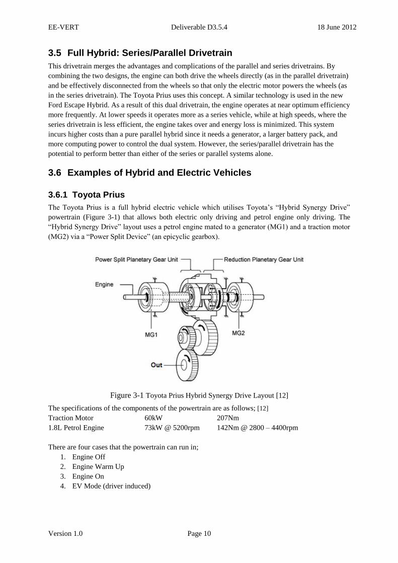
The Toyota Prius is a full hybrid electric vehicle which utilises Toyota’s “Hybrid Synergy Drive”
powertrain (Figure 3-1) that allows both electric only driving and petrol engine only driving. The
“Hybrid Synergy Drive” layout uses a petrol engine mated to a generator (MG1) and a traction motor
(MG2) via a “Power Split Device” (an epicyclic gearbox).
Figure 3-1 Toyota Prius Hybrid Synergy Drive Layout [12]
The specifications of the components of the powertrain are as follows; [12]
Traction Motor 60kW 207Nm
1.8L Petrol Engine 73kW @ 5200rpm 142Nm @ 2800 – 4400rpm
There are four cases that the powertrain can run in;
1. Engine Off
2. Engine Warm Up
3. Engine On
4. EV Mode (driver induced)

EE-VERT Deliverable D3.5.4 18 June 2012
Version 1.0 Page 11
When the driver requests low power and is at low speed then the engine will remain off and the
engine will also be off during decelerations.
When the vehicle is started, and the temperatures of components are low, the engine will start and
warm up. During this phase the engine will run at constant speed and vary torque depending on the
state of charge (SOC) of the battery. When stationary, the engine will run until the engine coolant
reaches a temperature threshold. When driving, the engine reverts to its normal engine off
conditions when this temperature threshold is reached.
The engine will turn on after the power the driver’s power request (via the accelerator pedal) reaches a
power threshold and if the vehicle’s speed reaches a velocity threshold. After the engine is switched
on the engine takes over supplying the majority of the power required by the vehicle. During periods
of high acceleration and deceleration the battery will supply or absorb some of the high peaks in
power to allow the engine to move slowly, reducing inefficient transients.
The Toyota Prius includes an EV button that allows the driver to force the engine to be off for longer.
This mode uses an increased power threshold and reduced velocity threshold to turn the engine on
and only operates if there is the battery’s SOC is high enough.
3.6.2 Chevrolet Volt
The Chevrolet Volt operates as a Range Extended Electric Vehicle (REEV). This means it operates as
a full electric vehicle with a range of 25 to 50 miles (40 to 80km), depending on terrain, driving
techniques and weather, until the 16kWh, lithium-ion battery pack reaches a minimum state of charge
(SOC) and the internal combustion engine (ICE) turns on and provides additional electricity to extend
its range by a further 310 miles (500km). [16]
The Volt can operate in two fully electric and two range-extended modes [15] as shown in Figure 3-2.
Electric Mode 1: Only the traction motor is used to propel the car using energy from the battery.
Electric Mode 2: The second electric motor/generator is declutched from the ICE (which is not
running), and together with the primary motor, they both now propel the vehicle increasing overall
efficiency for higher speed driving.
Range Extended Mode 1: When the battery reaches minimum state of charge the ICE comes on to
provide additional energy. This operates with the generator to provide electricity to the traction motor.
There is no mechanical connection between the ICE and the wheels in this mode and therefore it runs
un-throttled to achieve good efficiency.
Combined Drive Mode: This mode is used to increase efficiency at high speeds with low state of
charge. The generator (powered by the ICE) and the traction motor, act together on the planetary gear,
both providing tractive force. During this mode the generator still provides the electrical power used
by the traction motor.

EE-VERT Deliverable D3.5.4 18 June 2012
Version 1.0 Page 12
High SOC Low SOC
Figure 3-2 Operating Modes of Chevrolet Volt [15]
The specifications of the components of the powertrain are as follows; [15]
Traction Motor 116kW 370Nm
Generator 58kW 185Nm
1.4L Petrol Engine 63kW @ 4800rpm 130Nm @ 4250rpm
3.6.3 Nissan Leaf
The Nissan Leaf is a fully electric vehicle and is powered by a single 80kW AC synchronous motor
which draws its power from a 24kWh lithium-ion battery pack. This gives it a range of 100 miles
(160km) per charge based upon the US EPA LA4 City cycle. Once the battery is discharged there is
no alternative power supply. The battery must be recharged at a normal power socket or a public
charging station.
The Leaf has a driver-selected Eco mode. This reduces power provided to the heating and air
conditioning system and also uses a less aggressive pedal map. Eco mode will also increase
regenerative braking when the accelerator pedal is released. The combination of these measures could
increase range by up to 10%. [21]
To prevent the battery pack from overcharging, regenerative braking is reduced when the battery is
fully charged and also when the battery temperature is high or low to prevent damage to the battery.
[21]
4 EE-VERT Components and their characteristics
4.1 MIPEC
The EE-VERT concept requires the development of a flexible and configurable architecture for
optimising fuel-economy that includes energy recovery and energy harvesting. In this sense, one of

EE-VERT Deliverable D3.5.4 18 June 2012
Version 1.0 Page 13
the promising areas for improvement is the use of multiple power sources for feeding electric loads.
However, the connection and integration of multi power sources is not straightforward.
This assertion is especially apparent when examining the different options on the market: from micro
hybrid solutions working at 12-42V to full electric working at 400-600V with intermediate solutions
working at 42-100V. Furthermore, the range of energy sources available may work at different
voltage ranges. The same applies to the energy storage elements available on the vehicle.
So basically, the powernet has to accommodate several different power sources and storage systems,
operating at different voltages that should be capable of meeting the instantaneous electrical demands
that the vehicle may encounter under any condition.
To handle this scenario, a new device is required that has the following features:
a) Capable of computing the best storage/sources configuration based on vehicle conditions
b) Set up the appropriate energy flow path and transformation strategy
c) Combines the multi-voltage devices in one single power net line in a pseudo real time frame.
This device is described as the MIPEC (Multi-Input Power Electronics Converter).
Figure 4-1 MIPEC general architecture
The MIPEC architecture, Figure 4-1, is based on two principal stages, a Smart Sources
connection/selections Bays (SSB) and the DC/DC converter itself. The aim of SSB is to connect-
disconnect at the appropriate time and system conditions, based on an Energy Management strategy,
the different sources/storage devices into the power converter. The SSB technology depends on the
power/dynamics of the application (IGBT, MOSFET, SCR, etc.) and the directionality of the power /
energy source (an alternator is unidirectional while a battery is intrinsically bi-directional).
Regarding the DC/DC converter, several proposals have already been made with the objective of
effectively combining various power sources and energy storage elements [9]-[11]. Combination
strategies include sharing the output filter capacitor, sharing some switches and energy transfer
inductor and capacitor, and sharing a magnetic core. These input combination methods are shown in
Figure 4-2.

EE-VERT Deliverable D3.5.4 18 June 2012
Version 1.0 Page 14
(a) (b) (c)
Figure 4-2 MIPEC topologies (a) sharing output filter capacitor (b) sharing inductor, switch
and/or capacitor, (c) sharing magnetic core. [9]
Implementations (a) and (b) are typically used in renewable energy installations and hybrid / electric
vehicle applications since they are easily matched with requirements for energy flow and operation
modes. In renewable energy installations, these implementations take the form of a unidirectional
buck-boost converter. In hybrid and electric vehicles, these topologies are generally used to drive the
traction load. In this case, a bi-directional buck-boost converter is usually implemented such that the
converter acts as step up converter (boost converter) for one mode of operation and as step down
converter (buck converter) for the other mode of operation. Each power source is connected to the
DC-link by means of this bi-directional converter. Step up mode of operation is used in order to
transfer energy from each power source to the DC-link, whereas step down operation is used to charge
both UC tank and battery storage system and to recover the braking energy. Finally, solution (c) is
preferred for developments such as battery chargers, i.e., incorporating a connection to the grid for
recharging the battery.
Depending on vehicle requirements and the degree of hybridization, the DC/DC converter is built
using the most appropriate topology. Within the EE-VERT project a MIPEC, based on output filter
capacitor sharing topology, has been developed that demonstrates the ability to interface multiple
power sources (40V generator, solar panel, and a thermo-electric generator) into the 14V power net.
The prototype built may supply the 14V power net with up to 1.5kW with an efficiency higher than
93%.
4.2 Generator
EE-VERT has identified and selected a generator concept for the EE-VERT approach. The new
generator concept is based on a claw pole machine with integrated permanent magnets for flux
influence. Main characteristics of this concept are an increased efficiency during standard operation
and a short time boost power capability of up to 8kW during a braking phase of the vehicle.

EE-VERT Deliverable D3.5.4 18 June 2012
Version 1.0 Page 15
Figure 4-3 Exploded view of the generator prototype
Due to the promising characteristics from the simulation analysis the new generator concept has been
transferred into prototyping phase. During the first and second quarter 2010 it has been assembled.
Since quarter 3 of 2010 the generator is in vehicle integration phase. Figure 4-3 shows and exploded
view of the generator prototype. Figure 4-4 shows the assembled generator.
Figure 4-4 The assembled generator prototype
The generator is especially designed to deliver a high power during recuperation with up to 8 kW by
delivering additionally a high level of efficiency of up to 80 % during standard operation. The
dimensions of the new generator are only slightly increased. So this is a very interesting technology
concept also for electric machines for mild and micro hybrid vehicles.
4.3 Lithium ion battery
A 40V Lithium ion battery pack has been designed for use in the EE-VERT demonstrator vehicle. The
unit comprises of the following sub sections:
Battery Pack.
Power switching.
Cell voltage equalisation and battery pack monitor.
Cell bank voltage monitor.
The Battery Pack is designed to provide a nominal 40V and to accept a maximum charge power of
8kW for 10 seconds.

EE-VERT Deliverable D3.5.4 18 June 2012
Version 1.0 Page 16
The internal support electronics carries out the following functions:
Monitors the total pack voltage.
Monitors the pack temperature.
Monitors the battery charging/discharging current.
Equalises each cell voltage during charging.
Provide separate warning signals for cell over and cell under voltages.
In addition, the individual paralleled cell voltages can be monitored using the Cell Bank Voltage
Monitor using an external digital volt meter.
The measurement of charge/discharge current, total pack voltage and the kW hour usage are
communicated by CAN to a User Interface connector. The warning signals for over and under cell
voltages and pack temperature, are available as discrete signals in the User Interface connector. These
signals must be used by the Vehicle Controller (the central energy management ECU) to terminate
charging or discharging when the over and under limits have been reached to prevent cell damage.
Charging can be terminated by the Vehicle Controller sending a message to the generator to reduce
the current and also to tell the DC/DC to stop supplying current from the thermoelectric generator and
the solar panels.
The EE-VERT battery contains the functionality required by hybrid vehicles such as high power input
and output, and charge balancing. With a capacity of around 2.5kWh the unit could be used in micro
or mild hybrid designs with little modification. For electric traction full hybrids higher voltages and
storage capacity are required. This can be achieved by connecting further battery units in series to
give 80V, 120V and so on. Alternatively the basic battery module can be reconfigured and with more
cells higher voltages and capacities can be obtained. The battery monitoring system and cell balancing
system being reused.
4.4 Electric AC compressor actuator
The biggest benefit of an electric compressor is that it is independent of the engine. The motor speed,
and consequently mass flow, can be optimised in the most efficient manner (either for energy savings
or comfort provision). This is of particular benefit when the vehicle is stationary. With an engine
driven compressor the vehicle would have been idling, with quite a low engine speed and low mass
flow. An electric compressor can run at the speed to satisfy the demand.
For a car that uses a stop/start strategy, the AC would be off completely when the engine is off
whereas with an electric driven compressor it can still run. Another added benefit is that the electric
compressor is more responsive in that it can spin up to high speed very quickly, not something that
would happen if it was driven directly from the engine.
For the EE-VERT vehicle demonstrator the base power required from the electric compressor actuator
is 1.6kW at 6,000rpm with a maximum of 2.5kW at 8,000rpm and 40V minimum. The base load
torque is almost constant from 2,000rpm to 8,000rpm, 2.55Nm. The maximum load torque is 3Nm up
to 8,000rpm. The ambient temperature is 38°C.
UPT have researched and tested the two designs are fo and AC compressor actuatorr:
a) a surface permanent magnet synchronous motor;

EE-VERT Deliverable D3.5.4 18 June 2012
Version 1.0 Page 17
b) an interior permanent magnet synchronous motor.
Test results from the two prototypes indicates better performances from the SPMSM actuator on both:
steady-state and transients (even if it is slightly bigger in size than the IPMSM actuator prototype).
So, taking into account the efficiency, robustness and response characteristics, the SPMSM prototype
is the preferred choice for the A/C compressor electric drive application. It is also likely to be the
lower cost option. Further details are reported in D2.2.3. A further benefit is that the design can be
adapted for both the AC compressor and the water pump.
This electric actuator will be relevant to hybrid and pure EV vehicles for both the AC compressor and
water cooling circuits.
4.5 Engine cooling fan
On a conventional vehicle, the cooling fan is coupled to some heat exchanger to cool the vehicle
fluids. Typically on a passenger car the cooling system is made of a heat exchanger for the engine
water and a heat exchanger for the Freon of the climate circuit. The heat exchangers are exposed to
conducted air ventilation during normal vehicle cruising. If the non-forced ventilation is not enough, it
is possible to start forced ventilation through the use of the fan. Typically on conventional passenger
cars the fan is electrical.
On a hybrid vehicle the cooling request may be more complex. A thermal engine is still present and
the fan is still required to cool the engine water and the fluid in the climate circuit. The battery pack,
the inverter and the electric motor require to be cooled; typically they have to be cooled at a lower
temperature (35°- 50°C) than the thermal engine (90°C-100°C). Additional heat exchangers may be
required and the climate compressor may be used to provide the additional cooling power if the
thermal exchange with the external environment through the heat exchanger is not enough. All these
issues lead to a design of a complex additional thermal circuit for the electric driveline: many
different layouts are possible: just one fan may be used to cool a pack of more heat exchangers or
more fans may be used for each heat exchanger.
In any case the fan is electric and there is no need to change the voltage supply: the electrical power
request of the fan on a hybrid vehicle is not increased compared to a conventional vehicle. So the
electric fan will be supplied at 12V.
For such reason the EE-VERT approach to the smart electric fan (as discussed in D2.2.1 par 3.4) can
be used on a hybrid vehicle with the same benefit in terms of electric power demand reduction.
The fan has an impact on the electric balance of the vehicle and consequently on the vehicle fuel
consumption. Most fans have two rotation speeds: low and high speed. The control algorithm of the
fan is usually based on a threshold activation control (engine water, fluid of the climate circuit, water
of the electric powertrain), resulting in an activation based on three levels: zero, low and high speed.
The fan speed is related to the heat in that it is possible to subtract to the heat exchangers. So three air-
forced cooling levels are also available, for example: 1kW, 3kW, 10kW. If the heat exchangers
require, for example, 4kW of thermal cooling, the result of the actual control strategy is that, at the
end in stabilized conditions, 10kW from the fan will be requested, with the fan running at high speed.
Excessive cooling power is produced, causing waste energy.

EE-VERT Deliverable D3.5.4 18 June 2012
Version 1.0 Page 18
From an energy point of view, a better control would be to maintain the engine water temperature at a
fixed value (for example 98°C), using only the cooling power required to reach such a desired
temperature. The fan must provide a continuous speed regulation and not just a discrete three level
control. The electrical energy required with a continuous fan control is lower than the energy required
with a discrete speed levels control to achieve the same or even better performance (see Figure 4-5).
Level 1
Level 2
Level 3
Real ventilation need
Potential saving
Power [kW]
Figure 4-5 Potential energy saving on actual discrete level fan activation
For a conventional vehicle the estimated CO2 benefit in real life is about 1-2%, including the
additional benefits due to an improved thermal engine management. It is expected to have the same
benefit on a hybrid vehicle just related to the part of the mission in which the thermal engine is
switched on. The overall benefit during the full hybrid vehicle mission is expected to be lower, due to
the presence of parts of the mission in which the engine is off. Anyway when the engine is switched
off and the traction is provided by the electric drivetrain, cooling is required from the electric
drivetrain. The charge/discharge of the battery pack and the electric motor generating/recovering
power are source of heat due to their efficiency in power conversion. Depending on the efficiency of
the electric drivetrain a certain amount of heat must be dissipated. In this case the use of a smart fan
can lead to a reduction of the electrical power request also during the time in which the engine is
switched off.
4.6 Electrical fuel pump
The low pressure fuel pump on gasoline or diesel engines is used to sink the fuel from the tank, raise
the fuel pressure and send it to the injector system of the engine. Electric fuel pumps are generally
located in the fuel tank, in order to use the fuel in the tank to cool the pump and to ensure a steady
supply of fuel.
The fuel pump is managed differently according to the key and the engine status. At key-on, with the
engine off, the fuel pump is running for some seconds to ensure that there is sufficient fuel pressure to
the circuit for the engine to start. When the fuel pressure reaches the required level the fuel pump
stops. When engine starts during cranking, the fuel pump runs continuously to maintain the fuel
pressure in the circuit. Pressure is regulated through a passive pressure regulator with excess fuel
returned to the fuel tank. When the engine is running the fuel pump is always working at its maximum
motor speed, regardless of the actual fuel flow required for engine performance.

EE-VERT Deliverable D3.5.4 18 June 2012
Version 1.0 Page 19
The new management strategy adopted in EE-VERT (see D.2.2.1 par.3.3) will regulate the fuel rate of
the pump in order to assure the engine performance objectives while at the same time minimizing the
fuel recirculation. A minimum amount of fuel recirculation is required in a common rail injection
system. The regulation of the fuel rate is achieved through a current controlled driver applied on the
fuel pump DC motor.
Results indicate that a saving of about 6A @ 14V (84W electrical) may be expected under most
vehicle conditions. A hybrid vehicle is equipped with an internal combustion engine (ICE) and the
smart electrical fuel pump can be fitted to produce an electric energy saving on the low voltage (12V)
powernet. The hybrid vehicle will have the same savings as the conventional vehicle when the ICE is
operating. When the engine is switched off it is important to apply a strategy to switch off also the
fuel pump (typically the fuel pump is managed in conventional vehicles through the key signal) as in
Stop&Start vehicles.
4.7 VTG Turbo charger, electric actuator
The advantages of moving from vacuum control to electrical control of the VTG actuator include:
potential for more precise boost control
better response – reducing turbo lag
no need of vacuum as servo power
The VTG actuator has to fulfill the following requirements:
actuation range: 25mm
position accuracy: ±1%
response time: 100ms for 90% of full range
ambient temperature range -25°C to 150°C
vibration 15g rms
fit into the desired space and shape
CAN control
position feedback
failure status report via CAN
A novel actuator is being designed to meet both the VTG actuator requirements as well as being
universal actuator suitable for under-bonnet applications. The design of the device is based on a
brushless DC motor coupled to a two stage planetary gear with integrated control electronics. The
BLDC motor promises high reliability and high efficiency without the need for an external position
sensor.
The electrically powered VTG actuator is ideally suited for use on small turbocharged diesel engines
that could be fitted to hybrid vehicles.
EE-VERT Deliverable D3.5.4 18 June 2012
Version 1.0 Page 20
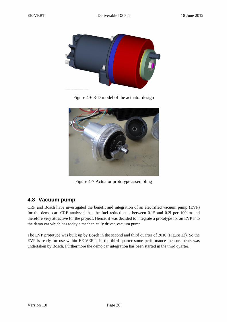
Figure 4-6 3-D model of the actuator design
Figure 4-7 Actuator prototype assembling
4.8 Vacuum pump
CRF and Bosch have investigated the benefit and integration of an electrified vacuum pump (EVP)
for the demo car. CRF analysed that the fuel reduction is between 0.15 and 0.2l per 100km and
therefore very attractive for the project. Hence, it was decided to integrate a prototype for an EVP into
the demo car which has today a mechanically driven vacuum pump.
The EVP prototype was built up by Bosch in the second and third quarter of 2010 (Figure 12). So the
EVP is ready for use within EE-VERT. In the third quarter some performance measurements was
undertaken by Bosch. Furthermore the demo car integration has been started in the third quarter.

EE-VERT Deliverable D3.5.4 18 June 2012
Version 1.0 Page 21
Figure 4-8 The electrified vacuum pump for the EE-VERT demonstrator car
The EVP is a dry running vane pump. It supports the brake booster at insufficient manifold
depression. This is especially useful for stop-start, catalyst heating, and for hybrid vehicles during
electric driving and free wheeling mode. It has a compact design at high flow rate performance with
low pressure pulse. The EVP is demand driven with reduced fuel consumption. It can provide stop-
start- and free wheeling operation at full brake performance. The EVP vehicle integration is now
independent from the combustion engine design with flexible mounting position possibility.
5 Components on Commercial Hybrid Electric Vehicles
This section investigates the electrification of components on the third generation Toyota Prius and
the first generation Chevrolet Volt and Nissan Leaf. The three vehicles all need to overcome the
problem of not having a 14V alternator on the vehicle to power auxiliary systems in the traditional
way.
Vehicle Hybrid Type
Toyota Prius Full Hybrid
Nissan Leaf Electric Vehicle (EV)
Chevrolet Volt Range Extended EV
Types of Hybrid Electric Vehicles on Sale
All three vehicles have a 12V auxiliary battery to supply the conventional electrical systems and use a
DC/DC converter to charge the 12V battery charged instead of a 14V alternator. This is primarily
because this method is easier, safer and cheaper than to redesign all auxiliary systems and motors to
run from the high voltage supply. This also allows systems to remain powered while the high voltage
system is off (door locking, dash board lighting, interior lights, radio).
All three vehicles have similar setups and it is assumed that the 12V battery powers all ancillaries
(door locks, interior lights, radio, dash board, etc.) until the ignition is on and HV contactors close.
After this everything is likely to be powered directly via the DC/DC convertor as it will output
typically 14V as the 12V auxiliary battery is being recharged.

EE-VERT Deliverable D3.5.4 18 June 2012
Version 1.0 Page 22
5.1 DC/DC Converter and Auxiliary Battery
5.1.1 Toyota Prius
The Toyota Prius is believed to be the first consumer automotive production engine that requires no
accessory belts as there are no belt driven components running off the engine apart from the hydraulic
oil pump as this is only required when the engine is running. The reduction of belt driven components
helps to reduce engine drag allowing the engine to operate more efficiently.
Figure 5-1 Toyota Prius Auxiliary Battery Set Up [12]
Apart from the AC compressor, all other components run from the 12V auxiliary battery supply which
is now backed up and charged by the DC/DC converter rather than an alternator. The DC/DC
converter assembly drops the NiMH HV battery pack nominal voltage (201.6V) in order to supply
electricity to the electrical components and auxiliary battery. The maximum power of the DC/DC
converter is not evident; however the 12V output is protected by 125A fuse indicating a maximum
value of less than 1.5kW [12]
5.1.2 Chevrolet Volt
In the Chevrolet Volt, the 12V auxiliary battery is mounted under the luggage compartment floor trim
which supplies the 44 conventional low voltage electrical systems on the car, including lighting,
power steering, cooling fans and pumps, entertainment and courtesy systems. This auxiliary battery is
charged via the DC/DC converter which draws power from the 360V high voltage Li-Ion battery,
similar to the Prius.
Figure 5-2 Chevrolet Volt DC/DC Converter
Once the car is on and ready, the electrical systems draw power directly from the DC/DC converter
rather than the auxiliary battery. This is located in the rear compartment beneath the load floor and

EE-VERT Deliverable D3.5.4 18 June 2012
Version 1.0 Page 23
replaces the belt-driven generator found in conventional vehicles. The DC-DC converter can output a
maximum current of 180A at 12V (2.16kW).
5.1.3 Nissan Leaf
The Nissan Leaf has a similar configuration where the 12V battery provides power to the vehicle
systems and features such as the audio system, supplemental restraint systems, headlights and
windshield wipers until the “ignition” is switched on. After the ignition is on, the Li-Ion HV (345V)
battery pack supplies power to the 12V systems and charges the 12V battery via a DC/DC converter,
which is protected by a 250A fuse when charging the 12V battery and 200A when powering systems.
The DC/DC converter and 12V battery are located in the front of the vehicle along with the inverter
and traction motor, presumably to take advantage of the packaging benefits of the Leaf not having an
ICE. The DC/DC junction box has a normal charge relay and a quick charge relay so that the circuits
are changed over according to the charge mode and is cooled via an internal cooling fin used to water
cool the DC/DC converter. [21]
An interesting point to note is that when the EV system is off, the 12 volt battery charges
automatically for 5 minutes every 5 days to prevent it from going flat. The charge timing resets to 5
days without charging the 12V battery if the vehicle is placed in the “Ready to Drive” position for
more than 5 minutes or the Li-Ion battery is charged for more than 5 minutes. [22]
5.2 Water Pump
5.2.1 Toyota Prius
The Toyota Prius employs a water cooling system that is independent from the engine water cooling
system to cool the inverter and generator (MG1). The traction motor (MG2) and HV battery assembly
including DC/DC converter are air cooled. This means two separate water pumps are required, both of
which are electric and run from the 12V circuit. MG1 and MG2 are identified in Figure 3-1.
Cooling System for Inverter and MG1 Control (Toyota G9020-47031)
The power management control ECU (HV CPU) receives the signals from the temperature
sensors for the inverter assembly, MG1 and MG2. Then, the HV CPU actuates the water
pump with a brushless DC motor over 3 levels using duty cycle control, in order to cool the
inverter and MG1.
This cooling pump is protected by a 15A fuse.
When the HV coolant temperature rises above a certain level, the HV CPU transmits a
radiator fan drive request signal to the engine controller. In response to that signal, the ECM
actuates the radiator fan to control the HV coolant temperature, cooling the inverter and MG1.
[12]
Engine Cooling System (Gates 42253 Water Pump)
The cooling system uses a pressurized forced circulation system with pressurized reservoir
tank

EE-VERT Deliverable D3.5.4 18 June 2012
Version 1.0 Page 24
The drive belt and pulley have been replaced by an electric water pump, protected by a 30A
fuse, which reduces the friction loss and reducing the weight.
A thermostat is located on the water inlet housing to maintain suitable temperature
distribution in the cooling system.
Warm water from the cylinder head sub-assembly is sent to the throttle body, to prevent
build-up of ice on it, and to cool the exhaust heat recovery system
An aluminium radiator core is used for weight reduction [12]
DC/DC Converter Cooling
The DC/DC Converter uses two electric fans, both running from the 12V network, which are
protected by a 40A and 30A fuse respectively.
5.2.2 Chevrolet Volt
The Chevrolet Volt is equipped with four fully independent cooling systems.
Power Electronics System: cools the battery charger and the power inverter module
Battery System: cools (or in some cases heats) the 360V high voltage battery
Engine System: cools and heats the ICE engine and when required and provides heat for the
passenger compartment
Electric Drive Unit System: cools the two motor generator units and electronics drive unit,
and provides lubrication for the various gears, bearings, and bushings
The water cooling systems each circulates a 50/50 mixture of anti-freeze and de-ionized water. GM
specifies that de-ionized water is required for high voltage isolation and to prevent corrosion from
effecting heat sink performance.
All four systems utilise their own separate radiator partition, and are sandwiched together and
mounted in the traditional location at the front of the engine compartment. These radiators (and
internally routed coolants) are primarily cooled by undercar airflow directed by an air-dam, through
the radiators. Airflow is augmented by a pair of variable speed, electrically powered (12V) cooling
fans controlled by the Engine Control Module (ECM).
Power Electronics Cooling System
A high flow 12V electric pump creates and controls the coolant flow, which passes through
(in order);
o the plug-in battery charger assembly
o the radiator
o the power inverter module (PIM)
o then back to the pump
The power electronics cooling system radiator is the upper half section of a dual radiator
assembly that is common with the high voltage battery cooling system
The Hybrid Powertrain Control Module controls the coolant pump as well as radiator fan
speeds based on a temperature sensors mounted in the radiator.
The system is also activated during plug-in charging
Battery Cooling System

EE-VERT Deliverable D3.5.4 18 June 2012
Version 1.0 Page 25
The Volt’s T-shaped Lithium Ion battery (360V) is mounted underneath the car and runs
down the centre tunnel and beneath the rear seating positions
The battery cooling system has its own 12V coolant pump, a refrigerant to coolant heat
exchanger and a 3-way coolant flow control valve to route coolant through the radiator, heat
exchanger, or bypass
The Hybrid Powertrain Control Module monitors various conditions including battery in/out
coolant and Li-Ion cell temperatures to establish battery heating, cooling or temperature
regulating requirements
It will then turn the coolant pump on or off, position the coolant flow control valve, and
depending on whether cooling or heating is required, request either the electric A/C
compressor to operate (cooling), or turn on the HV battery heater (heating). The battery
cooling/heating system can be activated when the vehicle is “on” and if necessary during
charging operations
Figure 5-3 Battery Cooling System
Engine Cooling System
The engine cooling system (and heater loop) uses the engine radiator, two 12V variable speed
radiator fans, an electric coolant heater pump (12V), a coolant flow bypass valve, a high
voltage (360V) coolant heater, and a cabin mounted heater core

EE-VERT Deliverable D3.5.4 18 June 2012
Version 1.0 Page 26
When the ICE is off, the coolant flow valve can direct coolant through the HV heater and the
cabin heating core in a short loop to prevent heat dissipating in to the engine coolant loop
When the ICE is on, the coolant flow valve links the heater and the ICE in the same parallel
loop. Subsequently, power will be reduced in the 360V heater and it will cycle on/off during
charge sustaining/extended range modes
Whenever the ICE is running, coolant through the engine is managed by a conventional belt-
driven water pump which ensures positive cooling flow that is automatically varied
proportionately with engine speed.
Electric Drive Unit Cooling System
The Volt drive unit uses a system of pressurised automatic transmission fluid that is used to
lubricate, control, and cool the transmission systems. The necessary pressure is primarily
created by a 3-phase AC electrical motor/pump assembly located within the transaxle. There
is also a more conventional mechanically driven gear pump to ensure transmission fluid
pressure and flows are always present when the ICE is running.
5.2.3 Nissan Leaf
The 100% EV Nissan Leaf does not have an ICE like the other two vehicles which obviously means
one less cooling system is required. Unlike the Chevrolet Volt and Toyota Prius, the HV battery is not
liquid cooled but air cooled. Nissan literature claims that the temperature of the battery is controlled
by varying the internal resistance of the battery. [23] What is more likely to happen is when the
battery temperature reaches a critical temperature the control system will limit the power it can deliver
until the battery drops to an acceptable temperature.
Unlike the HV battery, the EV system is water cooled and the high voltage cooling system serves the
traction motor, traction motor inverter, DC/DC converter and on board charger. Coolant is circulated
by two 12V electric water cooling pumps, protected by a 10A fuse, which are controlled by VCM
(vehicle control module) independently so that the amount of pressure feed is adjusted according to
the vehicle speed and water temperature. The electric water pumps feed coolant by pressure, which
circulates in the high voltage system cooling circuit.
An interface circuit is integrated into the electric water pumps to monitor the pump for any
malfunction, and it transmits a malfunction signal to VCM if necessary. [22]

EE-VERT Deliverable D3.5.4 18 June 2012
Version 1.0 Page 27
Figure 5-4 Nissan Leaf Cooling System
5.3 Air Conditioning Compressor
Traditionally vehicle air condition systems are driven from the crankshaft of the engine via a belt.
These systems require significant power and can increase fuel consumption as they increase engine
load.
This traditional system is not an option for the Prius, Volt or Leaf as a reciprocating engine is not
always available. All three instead use a system that uses an electric AC compressor with its own
inverter which draws power from the high voltage supply.
5.3.1 Toyota Prius
The A/C compressor is a 3-phase AC Denso ES14 unit which takes its power from the HV battery
pack (201.6V) through its integrated inverter. [14] The power draw is unknown but the compressor is
protected by a 10A fuse. If a short or open circuit occurs in the electric inverter compressor wiring
harness, the power management control ECU will cut off the A/C inverter circuit in order to stop the
power supply to the compressor motor.

EE-VERT Deliverable D3.5.4 18 June 2012
Version 1.0 Page 28
Figure 5-5 Toyota Prius Air Conditioning System [12]
In ECO mode, the air conditioning amplifier restricts the air conditioning system performance under
specified conditions, improving fuel economy. The amplifier is a controller that runs from the 12V
supply but the AC compressor cannot be activated unless the vehicle is in “ready mode” as power is
drawn from the HV battery. [12]
5.3.2 Chevrolet Volt
The Chevrolet Volt uses a high voltage air conditioning compressor similar to the Prius. The unit is
mounted on the front of the ICE, but takes no drive from the engine crankshaft. It is likely that the
positioning is a legacy from the Chevrolet Cruze model with which the Volt shares most of its
components including the 1.4L N/A version of the GM Family 0 engine.
Figure 5-6 Chevrolet Volt A/C Compressor
The system has its own 355V High Voltage inverter, electric motor and direct coupled compressor
allowing it to run independently from the engine. The electronic climate control module and the
Vehicle Integration Control Module (VICM) will command the electric A/C compressor to a speed
necessary to maintain a desired cooling level rather than cycle the electric A/C compressor on and off.
Under certain conditions the A/C cooling work can also be diverted to cool the high voltage battery
system.

EE-VERT Deliverable D3.5.4 18 June 2012
Version 1.0 Page 29
5.3.3 Nissan Leaf
As the Nissan Leaf has no reciprocating engine it has to use the high voltage supply to run the A/C
compressor. The electric scroll compressor (Part: AES28AV3AA) is used with a 345V DC brushless
motor, which consumes 2.1kW and has a 20A fuse, and is controlled by a 3-phase output inverter
with Intelligent Power Module. The system integrates the inverter, compressor, and motor, allowing
the compressor to operate at any speed.
The inverter communicates with the auto amplifier, and uses PWM to control the motor speed via the
drive circuit. The VCM controls the A/C relay so that the air conditioner can operate even in the
“Power Off” state. The remote air conditioner and timer air conditioner functions are enabled by this
control.
In addition, the VCM calculates the power that can be used by the air conditioning system based on
the Li-Ion battery status and vehicle status and sends it to the A/C auto amp. When ECO mode is
selected, the VCM sends the ECO mode signal to the A/C auto amplifier to control the air conditioner
at a lower rate than normally. [22]
5.4 Oil Pump
As only the Toyota Prius and Chevrolet Volt have an ICE, they are the only two vehicles that require
an oil pump for lubrication. Both the Prius and the Volt utilise a conventional mechanically driven oil
pump.
5.4.1 Toyota Prius
The lubrication circuit is fully pressurized by a trochoid gear type oil pump that is driven by the
crankshaft (oil pump drive). The engine has an oil return system where the oil is force-fed to the
upper cylinder head and returns to the oil pan through the oil return holes in the cylinder head. The
camshaft timing oil control valve regulates the oil pressure and then supplies oil into VVT-i
controller. [12]
5.4.2 Chevrolet Volt
The Chevrolet Volt uses the 1.4L N/A GM Family 0 petrol engine that is used on the Chevrolet Cruze
(turbo charged). Therefore it is assumed it uses the same engine lubrication system. It is a
mechanically controlled, variable-displacement flow control oil pump that monitors the rotation of the
engine to provide the exact amount of oil needed for various operating scenarios. This system is used
to reduce load/power demand on the engine by varying the amount of oil flow depending on rpm.
“By lowering the volume of oil we reduce the amount of energy, or torque, required
to pump the oil, without taking necessary lubrication away from the engine.
Reducing the torque demand reduces fuel consumption. It’s a simple, durable,
maintenance-free design that we have used in our transmissions for years and more
recently in our hybrid vehicles.”
Mike Katerberg, assistant chief engineer for the 1.4L engine. [17]

EE-VERT Deliverable D3.5.4 18 June 2012
Version 1.0 Page 30
5.4.3 Nissan Leaf
As the Nissan Leaf does not have an internal combustion engine the vehicle does not require an oil
pump.
5.5 Fuel Pump
5.5.1 Toyota Prius
The Toyota Prius has an electric “Fuel Returnless System” to reduce evaporative emissions. By
integrating the fuel filter, pressure regulator, charcoal canister and fuel sender gauge with fuel pump
assembly, it is possible to discontinue the return of fuel from the engine area and prevent temperature
rise inside the fuel tank. The fuel pump assembly has a compact fuel pump, fuel filter, pressure
regulator, fuel sender gauge and charcoal canister are integrated into it.
This pump runs from the 12V network and has a 20A fuse.
A fuel cut function is used to stop the fuel pump once any of the SRS airbags have deployed. When
the power management control ECU detects the airbag deployment signal from the airbag ECU
assembly, it transmits an engine off signal to the ECM. Upon receiving this signal, the ECM turns off
the circuit opening relay. After the fuel cut function has been activated, turning the power switch from
off to on (IG) cancels the fuel cut function, and the engine can be restarted. [12]
5.5.2 Chevrolet Volt
The electric fuel pump used on the Chevrolet Volt is a standard GM stock part as used on the GMC
Sierra which is the Delphi W0133-1870134 and runs from the 12V network.
5.5.3 Nissan Leaf
As the Nissan Leaf does not have an internal combustion engine the vehicle doesn’t have a fuel pump.
5.6 Power Steering
Traditionally power steering systems were hydraulic and drew their power from a belt driven pump.
Since the Toyota Prius, Chevrolet Volt and Nissan Leaf often or always drive without a reciprocating
engine, they have opted for an increasingly common alternative Electric Power Steering. A benefit of
electrified power steering systems is that manufacturing and servicing is a lot simpler due to no pipes,
vane pumps, pulleys or power steering fluid.
5.6.1 Toyota Prius
The Toyota Prius system uses a 12V DC electric power steering (EPS) motor, with a 60A fuse, which
only activates when the driver turns the steering wheel, reducing energy consumption. The steering
column assembly includes an integrated torque sensor, power steering motor and reduction
mechanism for a packaging benefit.

EE-VERT Deliverable D3.5.4 18 June 2012
Version 1.0 Page 31
The torque sensor detects the movement of the steering wheel, converting it in to an electric signal
which is sent to the controller (EPS ECU) which uses this to calculate amount of power assist the DC
motor should provide. It should be noted that the steering wheel retains a direct connection to the
wheels.
When the EPS ECU detects the auxiliary (12V) battery voltage has decreased beyond a limit, it
transmits an electric load control signal to the air conditioning amplifier in order to limit the electrical
usage. The air conditioning amplifier limits operation of rear window defogger and PTC heater until
the power steering ECU releases the limitation demand. [12]
Figure 5-7 Toyota Prius Electric Power Steering System [12]
1. Steering Column Assembly
Power Steering Motor
Torque Sensor
Rotation angle sensor
2. Power Steering ECU
3. Steering Gear Assembly
4. Brake Actuator Assembly and Skid control ECU
5.6.2 Chevrolet Volt
The Chevrolet Volt also uses an EPS similar to the Toyota Prius. It is a dual-pinion system (one is
used for steering, the other to add assist) with variable assist, rack-mounted electric power steering
system. A combined electric motor and sensing unit monitors steering angle, and delivers appropriate
assist to the steering gear in all scenarios. The system uses components that are rated at 12V. [18]
5.6.3 Nissan Leaf
The Nissan Leaf is equipped with a rack mounted EPS. The EPS control analyses data, such as
steering wheel turning force from the torque sensor and vehicle speed, amongst others, before
generating an optimum assist torque signal to the EPS motor.
The system consists of the EPS control, the 12V EPS motor protected by a 60A fuse (which provides
the assist torque by the control signal from EPS control unit), a Torque sensor (which detects the

EE-VERT Deliverable D3.5.4 18 June 2012
Version 1.0 Page 32
steering torque, and transmits the signal to EPS control unit) and a reduction gear (which increases the
assist torque provided from EPS motor with worm gears, and outputs to the column shaft).
Figure 5-8 Nissan Leaf Power Steering System [22]
In case of an error in the electrical system, the fail-safe function stops output signals to the EPS
motor. The EPS control unit will decrease assistance (by limiting current) if extensive steering at low
speeds causes the EPS control unit and EPS motor to heat up past a critical temperature. [22]
5.7 Vacuum Pump
Braking systems in electric cars are more complex as they need a system that can blend regenerative
and friction braking without a vacuum pump.
5.7.1 Toyota Prius
The Toyota Prius has an electronically controlled brake system to control the hydraulic pressure at the
four wheels. Instead of a conventional brake booster portion/vacuum pump, it consists of hydraulic
brake booster, brake actuator and brake booster pump assembly. This pump runs from the 12V
network and is protected by two 30A fuses in parallel.
During normal braking, the fluid pressure generated by the hydraulic brake booster does not directly
actuate the wheel cylinders, but serves as a hydraulic pressure signal. Instead, the actual control
pressure is obtained by regulating the fluid pressure of the brake booster pump assembly, which
actuates the wheel cylinders.

EE-VERT Deliverable D3.5.4 18 June 2012
Version 1.0 Page 33
Figure 5-9 Toyota Prius Braking Control [12]
The proportioning of brake force between the hydraulic brake and the regenerative brake varies with
vehicle speed and time. It is safe to assume that the SOC of the battery also has an effect on the level
of regenerative braking applied. The split between braking forces is accomplished by controlling the
hydraulic brake so that the total brake force of the hydraulic brake and the regenerative brake matches
the brake force required by the driver.

EE-VERT Deliverable D3.5.4 18 June 2012
Version 1.0 Page 34
Figure 5-10 Toyota Prius Braking Force Apportionment [12]
In the case of a fault occurring in the Skid Control ECU the hydraulic brake booster ensures braking
force is being applied. [12]
5.7.2 Chevrolet Volt
The Chevrolet Volt’s system uses a high-pressure hydraulic pressure accumulator to boost the braking
force. Extra solenoids in the system also control the blending of friction braking and regenerative
braking. The regenerative brakes can provide up to 0.2g of deceleration, after which there is a mixture
of regenerative braking and friction braking. [18]
“The Chevrolet Volt’s brakes are much faster than the brakes in a conventional car because the
Volt’s brakes use an accumulator which is more responsive and rapid than conventional vacuum-
boost brakes”
Valarie Boatman, Chevrolet Performance Integration Engineer [19]
The owner’s manual also states that the braking system controller blends the regenerative braking and
hydraulic disc braking to meet deceleration/driver requirement. [20]
“The controller interprets the braking request and uses regenerative
braking, conventional hydraulic braking, or a combination of both as
necessary. Because the controller applies the hydraulic brakes through
its high pressure accumulator, you may occasionally hear the
motor‐driven pump when it recharges the system.” [18]
5.7.3 Nissan Leaf
The Nissan Leaf has a similar ‘Electrically Driven Intelligent Brake’ system that is on the 12V circuit.
This integrates the control module, master cylinder, and brake booster and also controls the fluid

EE-VERT Deliverable D3.5.4 18 June 2012
Version 1.0 Page 35
pressure that is sent to the ABS actuator and electric control unit. The brake booster motor is
protected by a 60A fuse.
Figure 5-11 Nissan Leaf Electrically Driven Intelligent Brake System [22]
The control module controls fluid pressure applied to the brake callipers based on signals from the
sensors and also manages regenerative brake blending. Depending on the amount the brake pedal is
pressed, a motor within the brake booster presses upon the master cylinder piston to create a force to
generate fluid pressure. This pressure then sends an electrical signal to the EDIB.
In the case when power is not supplied to the brake booster (no voltage is generated) there is a backup
power source (Brake Power Supply Backup Unit) that supplies the required voltage. [22]

EE-VERT Deliverable D3.5.4 18 June 2012
Version 1.0 Page 36
Figure 5-12 Nissan Leaf Braking Force Schematic [22]
6 Summary
6.1 Components
Throughout the study of the hybrid and electric vehicles, some trends have become apparent. A
summary of the components in the three vehicles together with the EE-VERT concept is shown in
Figure 6-1 (voltages) and Figure 6-2 (maximum currents).
Toyota
Prius
Chevrolet
Volt
Nissan
Leaf
EE-VERT
Demo car
HV Battery 201.6V 360V 345V 40V
DC-DC Converter
(Low Voltage side) 12V 12V 12V 12V
Water Pump 12V 12V 12V 12V
A/C Compressor 201.6V 360V 345V 40V
Oil Pump Mechanical Mechanical N/A Mechanical, electrical
possible
Fuel Pump 12V 12V N/A 12V
Power Steering 12V 12V 12V Mechanical
Vacuum Pump 12V 12V 12V 12V
Figure 6-1 Summary of Components – Operating Voltages

EE-VERT Deliverable D3.5.4 18 June 2012
Version 1.0 Page 37
Toyota
Prius
Chevrolet
Volt
Nissan
Leaf EE-VERT
DC-DC Converter
(Low Voltage Side) ~125A 180A ~250A 150A
Water Pump 30A
Data
unavailable
10A Max I: 30A
A/C Compressor 10A 20A Max I: 40.2A
Oil Pump Mechanical N/A Mechanical
Fuel Pump 20A N/A 20A
Power Steering 60A 60A Mechanical
Vacuum Pump 2x 30A 60A Max I: 16.5A
Fuse values are used as an indication of the maximum current rating for the Prius and Leaf
Figure 6-2 Summary of Components – Maximum current rating
One of the key trends has been the way that most components electrified run from the 12V network
rather than the HV network. From a cost point of view this makes sense as it allows a lot of carryover
parts from conventional vehicles in the manufacturers range. For some components it also makes
sense from a safety point of view as there would be considerable risk at running heated seats at 350V
for instance.
The one system that runs directly from the high voltage network is the air conditioning system,
presumably due to its high and consistent power demand. When switching on the A/C in a Toyota
Prius the engine turns on and supplies the power the A/C system requires.
Another feature being implemented more and more is the inclusion of solar panels on the roof of the
vehicles to carry out various activities. In the Toyota Prius the solar panel powers the ventilation fan
keeping the cabin cool while the vehicle is parked [13] while the Nissan Leaf uses it to charge the
auxiliary 12V battery. [21]
As the Nissan Leaf is an EV and the Chevrolet Volt has an EV mode the A/C has to come from the
HV battery. This is one of the reasons, along with changing battery chemistries and longer EV ranges
that the battery packs of hybrids are increasing in voltage. For example the current Toyota Prius uses
a 201.6V NiMH battery pack but the upcoming plug-in version will use a 345V Li-Ion battery pack,
and claims an EV range of approximately 13 miles (21km).
6.2 Operating modes
There are a number of operating modes that have been developed within the EE-VERT project that
can be used by specific classes of hybrid vehicles. The modes include:
Brake regeneration
During braking engine braking will be increased by raising the output of the generator. This will be in
the region of 8kW for 10 seconds. This energy will be stored in the lithium ion battery and used to
power the electrical auxiliaries.
AC when stationary
Since the AC compressor is electrically operated and connected to the 40V powernet it will be
possible to run the AC system when the car is stationary with the engine at idle or even with the
engine off, provided that the SOC of the lithium ion battery is over 40%.

EE-VERT Deliverable D3.5.4 18 June 2012
Version 1.0 Page 38
Energy harvesting - Solar panel
The roof-mounted solar panel will be particularly beneficial when the car is parked in direct sunlight.
The electrical energy generated will be routed through the MIPEC into the powernet. Depending on
the circumstances the energy can be used to maintain the SOC of the lead acid battery, ventilate the
cabin or charge the lithium ion battery.
Reliability of Cranking Capability of the Lead-acid battery
The availability of the lithium ion battery to recharge a depleted lead acid battery offers the ability to
always ensure that the cranking of the engine is always possible even if there has been a significant
drain on the 12V battery, perhaps related to an extended parking period. This ability would be
managed through the MIPEC.

EE-VERT Deliverable D3.5.4 18 June 2012
Version 1.0 Page 39
CONCLUSIONS AND OUTLOOK
Hybrid vehicles have a high potential to reduce CO2 emissions but they require cost-intensive and
drastic technical modifications. EE-VERT has the objective to improve standard vehicles by an
overall energy management approach using smart components with a moderate increase in costs. EE-
VERT has developed a dual voltage architecture to accommodate multiple power sources and
electrically driven auxiliary devices, and use predictive algorithms for the energy optimised operation
of components and energy management. Table 1 shows the potential applicability of EE-VERT
elements to micro, mild and full hybrid vehicle types.
Type of Hybrid Micro Mild Full
Typical Voltages used 12V 30-50V/12V 150-450V/12V
EE-VERT Developments
Dual voltage architecture *
MIPEC *
50V generator
40V Lithium ion battery
Electrified auxiliaries:
A/C compressor actuator
Engine cooling fan
Fuel pump
Vacuum pump
VTG actuator
Operating modes
Brake energy recuperation
Solar energy harvesting
AC at idle or engine off
Ensure cranking ability of 12V SLI battery
*Multiple power source input concept
Table 1 Potential Applicability of EE-VERT Elements to Hybrid Vehicles

EE-VERT Deliverable D3.5.4 18 June 2012
Version 1.0 Page 40
References
[1] EE-VERT Deliverable 1.1.1, State of the art and standards.
[2] EE-VERT Deliverable 1.2.1, Mission profiles.
[3] EE-VERT Deliverable 1.3.1, Requirements report.
[4] EE-VERT Deliverable 2.1.1, Power Generation Report.
[5] EE-VERT Deliverable 2.1.2, Simulation Models for Power Generation.
[6] http://www.innovations-
report.com/html/reports/automotive/mass_production_micro_hybrid_technology_set_cut_125
526.html
[7] http://www.hybridcars.com/types-systems/where-are-micro-hybrids-26042.html
[8] S. Schaeck, et al., J. Power Sources (2008), doi:10.1016/j.jpowsour.2008.10.061
[9] S. H. Choung and A. Kwasinski (2008) “Multiple-Input DC-DC Converter Topologies
Comparison,” IECON 2008
[10] Y-M. Chen, Y-Ch. Liu, and S-H. Lin (2006) “Double-Input PWM DC/DC Converter for
High-/Low-Voltage Sources”, IEEE Transactions on Industrial Electronics, Volume 53, Issue
5, pages 1538-1545, October 2006
[11] K.P. Yalamanchili, and M. Ferdowsi (2005) “Review of multiple input DC-DC converters for
electric and hybrid vehicles“, IEEE Conference on Vehicle Power and Propulsion 2005
Other Hybrid Vehicle References
[12] Toyota Motor Corportation, “Toyota Prius Service Manual,” 2009
[13] Toyota Motor Corporation, “Toyota Prius Quick Reference Guide,” Toyota Motor Company,
2011
[14] Behr Hella Service, “Toyota Prius A/C Compressor,” Behr Hella Service
[15] Prof Dr U. D. Grebe and L. T. Nitz, “Voltec - Thr Propulsion System for Chevrolet Volt and
Opel Ampera,” MTZ, vol. 72, no. May 2011, pp. 4-11, 2011
[16] General Motors LLC, “Chevrolet Volt’s Revolutionary Voltec Electric Drive System Delivers
Efficiency With Performance,” 2010. [Online]. Available:
http://media.gm.com/content/dam/Media/documents/US/Word/101010_volt_launch/10_Chev
rolet_Volt_Propulsion.doc

EE-VERT Deliverable D3.5.4 18 June 2012
Version 1.0 Page 41
[17] General Motors LLC, “Special Oil Pump Helps Chevrolet Cruze Conserve Fuel,” GM News,
2010. [Online]. Available:
http://media.gm.com/media/us/en/gm/news.detail.html/content/Pages/news/us/en/2010/Aug/0
825_cruze
[18] General Motors LLC, “Chevrolet Volt: The Efficiency of an Electrically Driven Car with The
Handling Feel of a Sport Sedan,” GM Media, 2010. [Online]. Available:
http://media.gm.com/content/dam/Media/documents/US/Word/101010_volt_launch/10_Chev
rolet_Volt_Driving_Dynamics.doc
[19] General Motors LLC, “The 2011 Chevy Volt Brake Test,” 2010. [Online]. Available:
http://www.youtube.com/watch?v=UPdmTqs_YQs
[20] General Motors LLC, “Chevrolet Volt Owner Manual,” General Motors LLC, 2010
[21] Nissan Motor Co. Ltd, “Nissan Leaf Owners Manual,” Nissan Motor Co. Ltd, 2011
[22] Nissan Motor Co. Ltd, “Nissan Leaf Service Manual,” Nissan Motor Co. Ltd, 2010
[23] Nissan Motor Co. Ltd, “Why did Nissan develop an EV Battery?” Nissan Technology
Magazine, 2012. [Online]. Available: http://www.nissan-
global.com/EN/TECHNOLOGY/MAGAZINE/ev_battery.html