2.3.1 PsAula Artigo IndicePMVvisandoaoaperfeioamentodeclimatizadores 20150824165717

Project Lead The Way, Inc. Copyright 2007
IED – Unit 2 – Lesson 2.3 – Project 2.3.1 – Arbor Press – Page 1
Project 2.3.1a – Miniature Train
Purpose
Have you ever ridden on a train or owned a train set? The parts that make up the engine car on a train can vary depending on the make and model; however, all train engine cars have parts that are similar.
Collecting miniature trains or small replica versions of full size trains is a popular hobby for all ages. Some train collectors showcase their collection for everyone to see. They even build small scale towns and background scenery that trains run through while in the showcase. It is evident the time and detail that many train enthusiasts spend and create to make the showcase come to life.
Being able to read dimensioned drawings of an object is an important engineering skill. Understanding how to transpose these drawings into computer models of parts is also important. As you have learned in previous lessons, a sketch serves as the foundation for all the technical work that comes afterward. Being able to perform this technical work is an obvious must. Relaying this technical work correctly is a skill that allows a group of people to function as a design team.
Equipment
• Computer with 3D CAD solid modeling program
• Printer
• Engineer’s notebook
Procedure
This project will provide you with an opportunity to further develop your modeling skills, as well as your ability to use the computer as an efficient communication tool.
What you learned in the past two lessons will be systematically applied to this project.
In this project, you will model the parts needed for the Miniature Train Assembly. The parts with the dimensions are listed below.

Project Lead The Way, Inc. Copyright 2007
IED – Unit 2 – Lesson 2.3 – Project 2.3.1 – Arbor Press – Page 2
Train Parts List Item Quantity Name Description Material
1 1 Train Body ABS Plastic 2 1 Stack ABS Plastic 3 1 Hitch Magnet ABS Plastic 4 1 Hitch Peg ABS Plastic 5 4 Wheel ABS Plastic 6 4 Axle Peg ABS Plastic 7 2 Linkage Arm ABS Plastic 8 4 Linkage Peg ABS Plastic 9 1 Cow Catcher ABS Plastic
Train Tolerances All parts have the following tolerances: X.X = +/- .020 X.XX = +/- .010 X.XXX = +/- .005

Project Lead The Way, Inc. Copyright 2007
IED – Unit 2 – Lesson 2.3 – Project 2.3.1 – Arbor Press – Page 3
Part #1: Train Body

Project Lead The Way, Inc. Copyright 2007
IED – Unit 2 – Lesson 2.3 – Project 2.3.1 – Arbor Press – Page 4
Part #2: Stack
Part #3: Hitch Magnet
Part #4: Hitch Peg
Project Lead The Way, Inc. Copyright 2007
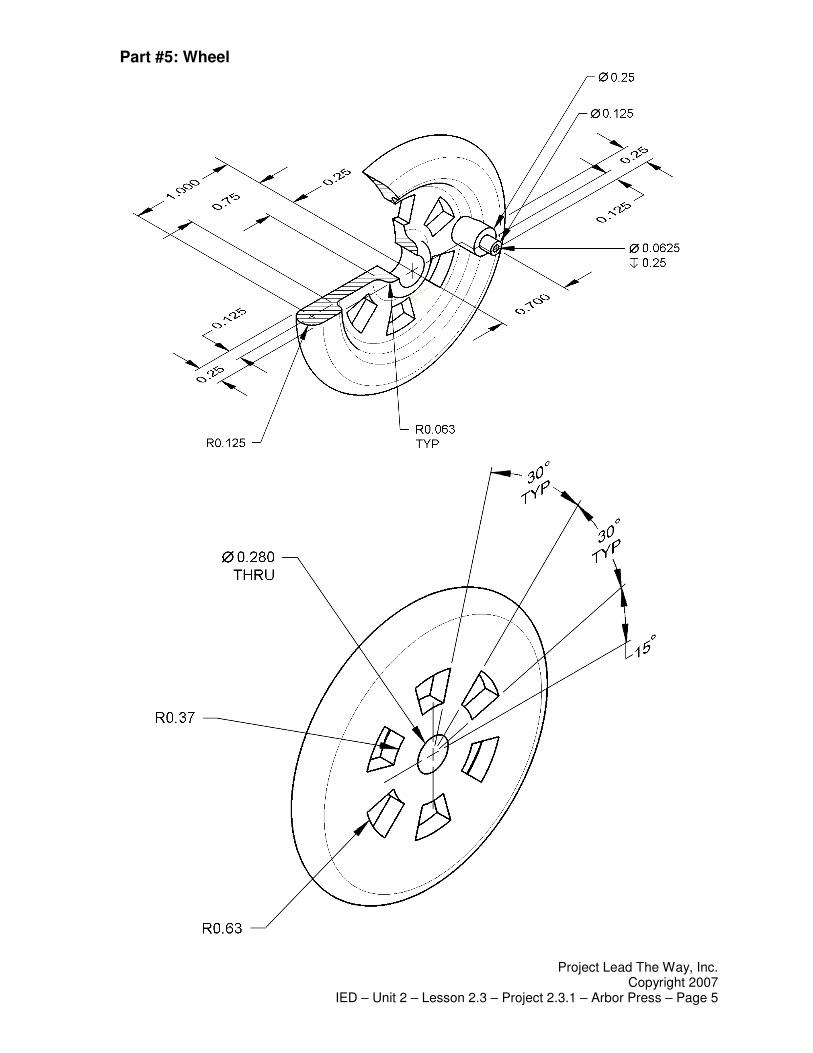
IED – Unit 2 – Lesson 2.3 – Project 2.3.1 – Arbor Press – Page 5
Part #5: Wheel

Project Lead The Way, Inc. Copyright 2007
IED – Unit 2 – Lesson 2.3 – Project 2.3.1 – Arbor Press – Page 6
Part #6: Axle Peg
Part #7: Linkage Arm
Part #8: Linkage Peg

Project Lead The Way, Inc. Copyright 2007
IED – Unit 2 – Lesson 2.3 – Project 2.3.1 – Arbor Press – Page 7
Part #9: Cow Catcher
Assembled Train

Project Lead The Way, Inc. Copyright 2007
IED – Unit 2 – Lesson 2.3 – Project 2.3.1 – Arbor Press – Page 8
Straight Track
Conclusion
1. Why are drawings composed of different line conventions?
2. What is the purpose of a sectional view?
3. What is the purpose of an auxiliary view?
4. Why are symbols used instead of words to identify hole types?

Project Lead The Way, Inc. Copyright 2007
IED – Unit 2 – Lesson 2.3 – Project 2.3.1 – Arbor Press – Page 9
5. What advantage is there to using algebraic equations instead of numerical values when defining the dimensions of a CAD model?
6. What three types of constraints can be applied to CAD sketches or models?
7. What advantages do CAD drawings have over paper sketches?