programmable thermal disinfection CALEFFI - allvalve.com.auallvalve.com.au/Files/PDF/Caleffi/6000...
12
01086/07 GB replaces dp 01086/05 Electronic mixing valve with programmable thermal disinfection 6000 series Function The electronic mixing valve is used in central systems that produce and distribute hot water for sanitary purposes. It is designed to ensure and maintain the temperature of the hot tap water distributed in the network when there are variations in the temperature and pressure of the incoming hot and cold water or in the draw-off flow rate. This particular series of electronic mixing valves is equipped with a special regulator that controls a set of programs for circuit thermal disinfection against Legionella. In addition it enables checking the temperature and time for thermal disinfection are actually reached and undertaking the appropriate corrective action. All the parameters are updated every day and logged, recording the temperatures by time. Depending on the type of system and habits of the consumer, it is possible to program the temperature levels and the operation times in the most appropriate manner. In addition, it is fitted for a monitoring and remote control connection. Patented Product range 6000 series Electronic mixing valve with programmable thermal disinfection. Threaded version. sizes 3/4” - 1” - 1 1/4” - 1 1/2” - 2” 6000 series Electronic mixing valve with programmable thermal disinfection. Flanged version. sizes DN 65 and DN 80 CALEFFI cert. n° 0003 ISO 9001 Technical specifications Valve body Materials: Body: brass EN 12165 CW617N Ball: brass EN 12165 CW617N, chrome plated Hydraulic seals: NBR Max working pressure (static): 10 bar Max inlet temperature: 100°C Thermometer temperature scale: 0 – 80°C Hot and cold water connections: 3/4” – 2”F Mixed water connection: 3/4” – 2” F with union Flanged connections: DN 65 and DN 80, PN 16 can be coupled with counterflanges EN 1092-1 Actuator for threaded version Electric supply: 230 V (ac)- 50/60 Hz directly from the regulator Power consumption: 8 VA Protective cover: self-extinguishing V0 Protection class: IP 44 Ambient temperature range: -10 – 55°C Length of supply cable: 0,9 m Actuator for flanged version Electric supply: 230 V (ac)- 50/60 Hz directly from the regulator Power consumption: 10,5 VA Protective cover: self-extinguishing V0 Protection class: IP 65 Ambient temperature range: -10 – 55°C Length of supply cable: 2 m Mixing valve performance Accuracy: ± 2°C Max working pressure (dynamic): 5 bar Max ratio between inlet pressures (C/H or H/C) with G = 0,5 Kv: 2:1 Digital regulator Material: - box: self-extinguishing ABS white RAL 1467 - cover: self-extinguishing SAN smoked transparent Electric supply: 230 V (ac) 50/60 Hz Power consumption: 6,5 VA Adjustment temperature range: 20 – 65°C Disinfection temperature range: 40 – 85°C Ambient temperature range: 0 – 50°C Protection class: IP 54 (wall mounting) (class II appliance). Contact capacity: - mixing valve control: 5(2) A / 250 V - alarm relay (R2): 5(2) A / 250 V - relay 1, 3, 4: 10(2) A / 250 V Fuses: 1 A Charge reserve: 15 days In case of a mains failure, with a 3-cell rechargeable buffer battery of 150 mAh enabling via jumpe Battery charging time: 72 h Conforming to Directives: CE Temperature sensors: - type of sensitive element: NTC - working range: -10 – 125°C - resistance: 10000 Ohm at 25°C - time constant: 2,5 s Max distance of the flow sensor: 25 m Max distance of the return sensor: 1000 m
Transcript of programmable thermal disinfection CALEFFI - allvalve.com.auallvalve.com.au/Files/PDF/Caleffi/6000...

01086/07 GBreplaces dp 01086/05
Electronic mixing valve with programmable thermal disinfection
6000 series
FunctionThe electronic mixing valve is used in central systems that produceand distribute hot water for sanitary purposes.It is designed to ensure and maintain the temperature of the hot tapwater distributed in the network when there are variations in thetemperature and pressure of the incoming hot and cold water or inthe draw-off flow rate.This particular series of electronic mixing valves is equipped witha special regulator that controls a set of programs for circuitthermal disinfection against Legionella.In addition it enables checking the temperature and time forthermal disinfection are actually reached and undertaking theappropriate corrective action. All the parameters are updatedevery day and logged, recording the temperatures by time.Depending on the type of system and habits of the consumer, it ispossible to program the temperature levels and the operation timesin the most appropriate manner.
In addition, it is fitted for a monitoring and remote controlconnection.Patented
Product range
6000 series Electronic mixing valve with programmable thermal disinfection. Threaded version. sizes 3/4” - 1” - 1 1/4” - 1 1/2” - 2”6000 series Electronic mixing valve with programmable thermal disinfection. Flanged version. sizes DN 65 and DN 80
CALEFFIcert. n° 0003ISO 9001
Technical specifications
Valve bodyMaterials: Body: brass EN 12165 CW617NBall: brass EN 12165 CW617N, chrome platedHydraulic seals: NBR
Max working pressure (static): 10 barMax inlet temperature: 100°CThermometer temperature scale: 0– 80°C
Hot and cold water connections: 3/4”– 2”FMixed water connection: 3/4”– 2” F with union Flanged connections: DN 65 and DN 80, PN 16 can be coupled
with counterflanges EN 1092-1
Actuator for threaded versionElectric supply: 230 V (ac)- 50/60 Hz directly from the regulatorPower consumption: 8 VAProtective cover: self-extinguishing V0Protection class: IP 44Ambient temperature range: -10– 55°CLength of supply cable: 0,9 m
Actuator for flanged versionElectric supply: 230 V (ac)- 50/60 Hz directly from the regulatorPower consumption: 10,5 VAProtective cover: self-extinguishing V0Protection class: IP 65Ambient temperature range: -10– 55°CLength of supply cable: 2 m
Mixing valve performanceAccuracy: ± 2°CMax working pressure (dynamic): 5 barMax ratio between inlet pressures(C/H or H/C) with G = 0,5 Kv: 2:1
Digital regulatorMaterial: - box: self-extinguishing ABS white RAL 1467
- cover: self-extinguishing SAN smoked transparent
Electric supply: 230 V (ac) 50/60 HzPower consumption: 6,5 VA
Adjustment temperature range: 20– 65°CDisinfection temperature range: 40– 85°CAmbient temperature range: 0– 50°C
Protection class: IP 54 (wall mounting)(class II appliance).
Contact capacity: - mixing valve control: 5(2) A / 250 V- alarm relay (R2): 5(2) A / 250 V- relay 1, 3, 4: 10(2) A / 250 V
Fuses: 1 ACharge reserve: 15 days In case of a mains failure, with a
3-cell rechargeable buffer battery of 150 mAhenabling via jumpe
Battery charging time: 72 h
Conforming to Directives: CE
Temperature sensors: - type of sensitive element: NTC- working range: -10– 125°C- resistance: 10000 Ohm at 25°C- time constant: 2,5 s
Max distance of the flow sensor: 25 mMax distance of the return sensor: 1000 m

Energy savings
Energy savings rules advice to use mixing valves on water deliverysystems for sanitary use with storage, to limit the temperature of thewater at the inlet of the delivery network. The purpose of limiting thetemperature is to reduce passive dispersion through the deliverynetwork as much as possible, besides prevent delivering water ata higher temperature than necessary.
Reference documents
With regard to the prevention and control of Legionella, see theNational Regulations and applicable Code of Practice.
Applications
The electronic mixing valve is typically used in central systemsserving hospitals, nursing homes, sports centres, shopping malls,hotels, campsites and boarding schools. In these structures withtheir collective use, it is more than ever necessary to control andprevent legionnaire’s disease in a programmed manner, managingthe disinfection times in the best possible way.
Legionella-distribution temperature
In central systems that produce hot water for sanitary purposes withstorage, in order to prevent the growth of dangerous Legionellabacteria, the hot water must be stored at a temperature of at least60°C. At this temperature it is certain that the growth of the bacteriathat can lead to the illness called legionnaire’s disease will be totallyinhibited.These temperatures, however, are too high to be able to be useddirectly by the consumer; hot water at these levels can causesevere burns. It is therefore necessary to reduce the temperature ofthe hot water distributed in the network to a lower value compatiblewith use. In addition, not only the storage but also the entire distributionnetwork needs thermal disinfection at regular intervals. Otherwisethe bacteria would quickly form there too.
In the light of all this, it is therefore advisable to install an electronicmixing valve that is able to:
· reduce the temperature of the distributed water to an adjustablevalue lower than that of storage
· keep the mixed water temperature constant as the temperatureand pressure at the inlet or the draw-off flow rate of the mixedwater vary
· allow programming thermal disinfection with a higher temperaturethan the adjustment value, in the necessary time and in periods withless frequent consumption (nighttime).
Thermal disinfection
The drawing alongsideshows the behaviour ofLegionella Pneumophilabacteria as theconditions vary in thetemperature of the watercontaining the bacteria,in laboratory cultures.To ensure correctthermal disinfection, it isnecessary to go up tovalues of no less than60°C.
0
10
20
30
40
50
60
70 Instant death of bacteria
Death of 90% of bacteria in 2 minutes
Death of 90% of bacteria in 2 hours
Optimum temperaturefor growth of bacteria
Surviving bacteria inactive
Dimensions
C A
A
AB
°C
0
20
80
6040
DA
3/4"1”
1 1/4”1 1/2”
2”
B747585100110
C200212226248266
D8595140150170
E145145145145145
F180180180180180
Code600050600060600070600080600090
Weight (kg)
1,31,72,32,95,0
ADN 65DN 80
B235235
C600600
D275275
E145145
F180180
Code600006600008
Weight (kg)
2830,4
F
E
G
F
E
G
G105105105105105
G105105
AA
AB
CD
°C
0
20
8060
40
100
120
OkMenuShock
Ok
Mixed °C Return °C
tuesday 13/02/2006
Adjustmentrunning
OkMenuShock
Ok
Mixed °C Return °C
tuesday 13/02/2006
adjustmentrunning

COLD
HO
T
MIX
Characteristic components
1
3
2
6
4
5
3
2
6
4
°C
0
20
80
6040
°C
0
20
8060
40
100
120
tuesday 13/02/2006
adjustmentrunning
1) Legiomix digital regulator
2) Mixing valve
3) Mixing valve actuator
4) Mixed water flow sensor
5) Return sensor
6) Mixed water flow thermometer
Operating principle
At the mixing valve inlet there is hot water from the storage and cold water from themains. At its outlet there is the flow mixed water.By means of a specific sensor, the regulator measures the temperature of the mixedwater at the valve outlet and operates the mixing valve to maintain the set temperature.
It modifies the flows of hot and cold water at the inlet to bring the temperature of theoutlet water to the set value.Even if there are drops in pressure due to hot or cold water usage or temperaturevariations at the inlet, the mixing valve automatically adjusts the flow rate of water untilit obtains the set temperature.
The appliance incorporates a digital clock and allows programming anti-legionelladisinfection treatment on the plumbing system.The system is disinfected by raising the water temperature to a specific value for aspecific time duration.
For the best thermal disinfection control, in this type of system it may also benecessary to measure the temperature of the water returning from the network,measured with the recirculation sensor. When this measurement is available, it isused in order to check and control the temperature reached over all or part of thenetwork, since the sensor can be located at a significant remote point of the system.
The appliance is equipped with an RS-485 serial port for remote querying andsetting and via specific relays it carries alarm signals and controls for othersystem devices outside.
°C
020
80
6040
recirculation sensor
flow sensor

Hydraulic characteristics
Δp (bar)
1,5
Δp (m w.g.)
100
200
500
5 10 20 50Fl
ow ra
te(l/
min
) (m
3 /h)
1,0
0,5
0,3
0,2
0,1
0,05
15
10
5
3
2
1
0,5
3/4”
50
2
201
1” 1 1/4” 1 1/2” 2”
Kv (m3/h)3/4” 5,21” 9,0
1 1/4” 14,51 1/2” 23,0
2” 32,0
3/4” 0,5 6,41” 0,7 11,0
1 1/4” 1,0 17,81 1/2” 1,5 28,0
2” 2,0 39,0
Recommended FLOW RATES toensure stable operation and an accuracy of ± 2°C
Minimum(m3/h)
Maximum*(m3/h)
* Δp = 1,5 bar
Δp (bar)
1,5
Δp (m w.g.)
1000
2000
50 100
200
Flow
rate
(l/m
in)
(m3 /
h)
1,0
0,5
0,3
0,2
0,1
0,05
15
10
5
3
2
1
0,5
DN 65
500
20
200
10
DN 80
Kv (m3/h)DN 65 90,0DN 80 120,0
DN 65 4,0 110,0DN 80 5,0 146,0
Minimum(m3/h)
Maximum*(m3/h)
* Δp = 1,5 bar
Recommended FLOW RATES toensure stable operation and an accuracy of ± 2°C
Back panel
1514
1312
1110
98
76
54
32
1
18 17 16
2120
19
ClosesCommonOpensEarthEarthNeutralLive
Relay 4
Relay 3
Relay 2
Relay 1
Mix
val
veE
lect
ricsu
pply
230
V
Rel
ay c
onta
cts
FlowCommon
Return
RS485
Appliance fuse1 A - 250 V delayed
Mix valve fuse1 A - 250 V delayed
Tem
pera
ture
sens
ors
Disablingbutton
PIN code
Appliancereset button
Screwfor closing front
with hole forsealing
Terminal fortemperature
sensors
RS485interfaceterminal
Contacts for thermalshock function enablingjumper
Shock enabled
Shock disabled
Battery connected Battery disconnected
PIN
disa
ble
Rese
t
Battery connection
Thermal shockenabling
To remove the electrical wiring base you need to turn it round and extract it from its housing.
Connecting sensors:The cable connecting the flow and return sensors with the regulator must be installed in adedicated raceway. If the connecting cable is put into a raceway with other live cables then youmust use a grounded shielded cable.
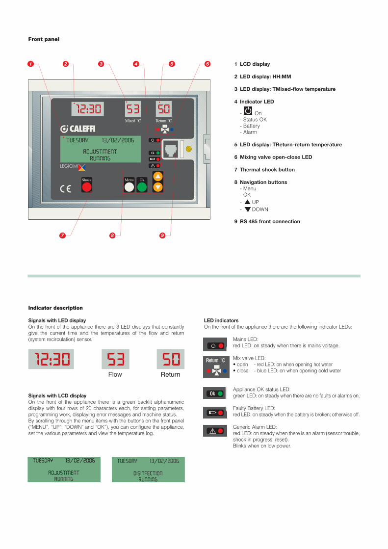
Front panel
OkMenuShock
Ok
Mixed °C Return °C
tuesday 13/02/2006
adjustmentrunning
1
8 97
65432
Indicator description
Signals with LED display On the front of the appliance there are 3 LED displays that constantlygive the current time and the temperatures of the flow and return(system recirculation) sensor.
Signals with LCD displayOn the front of the appliance there is a green backlit alphanumericdisplay with four rows of 20 characters each, for setting parameters,programming work, displaying error messages and machine status.By scrolling through the menu items with the buttons on the front panel(“MENU”, “UP”, “DOWN” and “OK”), you can configure the appliance,set the various parameters and view the temperature log.
LED indicatorsOn the front of the appliance there are the following indicator LEDs:
Mains LED:red LED: on steady when there is mains voltage.
Mix valve LED:• open - red LED: on when opening hot water• close - blue LED: on when opening cold water
Appliance OK status LED:green LED: on steady when there are no faults or alarms on.
Faulty Battery LED:red LED: on steady when the battery is broken; otherwise off.
Generic Alarm LED:red LED: on steady when there is an alarm (sensor trouble,shock in progress, reset).Blinks when on low power.
Ok
Return °C
1 LCD display
2 LED display: HH:MM
3 LED display: TMixed-flow temperature
4 Indicator LED
- On - Status OK- Battery- Alarm
5 LED display: TReturn-return temperature
6 Mixing valve open-close LED
7 Thermal shock button
8 Navigation buttons- Menu- OK- UP- DOWN
9 RS 485 front connection
tuesday 13/02/2006
adjustmentrunning
tuesday 13/02/2006
disinfectionrunning
Flow Return

Work status
Depending on the time, according to the programs entered, the appliance may be in one of the following work modes:
• Adjustment;
• Disinfection;
• Flushing;
• Thermal shock (this function takes priority over the preceding ones);
In the event of trouble due to the appliance or the system, the device manages and reports the alarm and, depending on the situation, may maintainoperation or not. So the statuses include:• On with alarm• Off with alarm
The appliance is equipped with a chargeable battery that enables keeping the clock working in the event of a mains power failure.In the event of a blackout, in order to ensure the longest operating time possible for the battery, the appliance is in the status of:• Off with Low Power.
Adjustment In this mode the appliance continually checks the temperature detected by the flow sensor and as a result adjusts the mixing valve so that the flowtemperature is equal to the set point.
Disinfection In this mode the appliance runs a disinfection phase, which consists of taking the water temperature up to a pre-set value for a specific duration, suitablycontrolling the mixing valve.It is possible, with the menu, to set the days of the week when disinfection must be carried out.
At the end of disinfection, the statistical data relating to the disinfection that has just been concluded are stored in memory.Access to and exit from this mode take place automatically according to a time for starting (TIMEON) and ending (TIMEOFF) that the user can set.
If, in the time span (Time OFF - Time ON), the actual disinfection time is reached tDIS greater than the set tMIN, the disinfection is concluded with apositive outcome. It automatically exits this status and returns to adjustment.
If it is not possible to reach a sufficient time tDIS, the disinfection phase anyhow ends at Time OFF.
t1 t2
tDIS = Σ ti > tMIN
TIME ON TIME OFF
SET2 - PRG1A
SET3 - PRG1B of 2
CHECK ON DISINFECTION
Temperature
Time
Example:
Time ON: 2:00Time OFF: 3:00tMIN: 30 minProgram: 1ATdisinfection: 60°C
If, in the time span of 1 hour, there is a temperature higher than 60°C for at least 30 minutes, disinfection has beensuccessful and the regulator returns to adjustment. Otherwise, disinfection anyhow ends at 3:00.

Programs
The operation of the regulator, during disinfection, can be set according to different programs, chosen according to the type of system and itsmanagement:
Program 0 (default)This program features continual adjustment of the flow temperature with automatic disinfection in a time band that can be set. With this programthe return sensor is not used; if present, it is only used as a monitor.During the phase of disinfection, the temperature of the flow sensor must be above SET2 for a time tDIS at least equal to tMIN, if this occursthen disinfection has been successful.As soon as there are the conditions to be able to consider disinfection successful, it is stopped. If disinfection is not successful there is no alarmsignal.
Program 1AThis program features continual adjustment of the flow temperature with automatic disinfection in a time band that can be set. With this programthe return sensor is not used; if present, it is only used as a monitor.During the phase of disinfection, the temperature of the flow sensor must be above SET2 for a time tDIS at least equal to tMIN, if this occursthen disinfection has been successful.As soon as there are the conditions to be able to consider disinfection successful, it is stopped.If it is not possible to reach the disinfection temperature or it is not possible to hold it for a sufficient time, the alarm for unsuccessful disinfectionis generated. The alarm is recorded in the log.
Program 1BThis program can only be set if the return sensor is set as present.It is identical to the previous program, the only difference lies in the fact that the successful outcome of the disinfection phase is checked viathe return sensor in relation to SET3 instead of via the flow sensor in relation to SET2.As soon as there are the conditions to be able to consider disinfection successful, it is stopped.If it is not possible to reach the disinfection temperature or it is not possible to hold it for a sufficient time, the alarm for unsuccessful disinfectionis generated. The alarm is recorded in the log.
Program 2This program can only be set if the return sensor is set as present.It is identical to the previous program, the only difference lies in the fact that, if after a wait time (tWAIT) since the start of disinfection the returntemperature does not reach SET3, the flow temperature SET2 is increased by a value equal to (SET3 - TR reached), considering the fact thatSET2 anyhow cannot exceed the limit of SETMAX.This correction procedure (increasing only) of the disinfection SET is iterative: if necessary, it is repeated in the time span defined by TimeONand TimeOFF at each time interval equal to tWAIT.As soon as there are the conditions to be able to consider disinfection successful, it is stopped.If it is not possible to reach the disinfection temperature or it is not possible to hold it for a sufficient time, the alarm for unsuccessful disinfectionis generated. The alarm is recorded in the log.
Thermal disinfection
The temperatures and corresponding disinfection times for the network must be chosen according to the type of system and the relatedintended use. In the light of the requirements of the most advanced world legislation on this matter, the following criteria can generally befollowed:
T = 70°C for 10 minutes
T = 65°C for 15 minutes
T = 60°C for 30 minutes
Thermal disinfection is generally performed at times of reduced use of the system, for example at nighttime; this is to minimize the risk of usersgetting scalded. It is recommended to perform thermal disinfection every day and at least once a week.
Thermal disinfection program guide table
Type of check Progr. Use Adjustment temperature Disinfection temperaturereturnsensor
Adjustment and simple disinfection 0 NO Flow: (SET 1) Flow: (SET 2)no check 50–55°C 60°CAdjustment and disinfection check 1A NO Flow: (SET 1) Flow: (SET 2)on the flow temperature 50–55°C 60°CAdjustment and disinfection check 1B YES Flow: (SET 1) Recirculation: (SET 3)on the return temperature to the heating plant 50–55°C 57°CContinual disinfection 1B YES -- Recirculation: (SET 3)
55°C -24 hAdjustment and check on disinfection with 2 YES Flow: (SET 1) Recirculation: (SET 3)modification of the flow temperature 50–55°C 55°C with modification of flowaccording to the return temperature up to the max value

Reset
On the back of the panel there is the reset button, if it is necessary to restore the initial settings.If the date and time are not set after the reset, the regulator will only make the adjustment according to the default settings.
Actuation relays
On the power and terminals board there are the contacts of the relays used to govern the auxiliary equipment and to report alarms.
• Relay 1: circulation pump (on in disinfection).
• Relay 2: general alarm (sensor fault, battery fault, blackout or loss of current time). This relay is connected via the NC contact.
• Relay 3: second thermostat.
• Relay 4: flushing valves.
Rese
t
FlushingThe appliance goes into this mode automatically at the end of the disinfection phase and it can be used for example to make the watertemperature return to the adjustment value more quickly or to periodically clear the storage of any impurities.
Thermal shock In this mode, the appliance regulates the flow temperature on the shock setting for a time that can be set. It is possible to start thermal shock on pressing the specific button on the front of the appliance (pressing it for at lease 5”) while the work screenis displayed, or to program it with the menu item for deferred execution (countdown in minutes), or by remote control.After activating the procedure, it is anyhow possible to stop it by pressing the shock button and confirming it with the “OK” button(display guided procedure), or by remote control.
At the end of the Thermal Shock phase the appliance goes back into the “adjustment” function.
Low PowerThis mode is entered if there is a mains power failure.The appliance continues running the internal date clock, however in this state there is no power to switch over the relays so the regulator willperform neither adjustment nor disinfection.When the mains power comes back on, the blackout is recorded in the log and the regulator returns to operating as programmed, unless themains failure lasted long enough to run down the battery completely. In this case the appliance will reset when the mains power comes back on.In the event of a reset or an extended power failure, the default settings are restored.
Relay contact for recirculation pump and hot waterstorage thermostat 2°
Here we give the electrical connection of relay 1 when there is theclock for managing the recirculation pump times.
Here we give the electrical connection of relay 3 for connection tothe second thermostat of the hot water storage.
LN
Recirculation pump
Relay 1
1 2
L
N
Hot water storage primary pump
Relay 3T160°C
T270°C
5 6

Log
The “log” is a FIFO list (loop buffer) that is continually updated and records parameters relating to the phases of adjustment and disinfectionthat took place during the day.The last 40 days are saved, after which the data relating to the less recent day are overwritten and so on.Every hour the hourly averages of the flow and return temperatures are saved to Eeprom, while the alarms are saved at the time when theyoccur.At any time it is possible to view the average hourly values of the current day (obviously the ones already recorded).The data on disinfection are saved when disinfection ends.It is possible to view the log on the display (via the specific menu item) or remotely via the RS485 serial interface.
The parameters saved in the log are:- Date (day, month, year)- Set program. This is saved when disinfection starts.- tDIS: actual disinfection time (in steps of minutes).When the set program is 0 or 1A, this parameter is the time when the temperature of the flow sensor was greater than SET2.When the set program is 1B or 2, this parameter is the time when the return sensor was greater than SET3.This is helpful when it is less than tMIN, to understand how much greater the span of TIME ON: TIME OFF should be to complete disinfection.- TRMAX: Maximum temperature of the return sensor during disinfection (if there was disinfection that ended on that day).- TRMIN: Minimum temperature of the return sensor during disinfection (if there was disinfection that ended on that day). It is calculated from the time when the return sensor measured a value greater than SET3, that is starting from the time when the disinfection starts being effective.
- Alarms AL1, AL2, AL3, AL4, AL5, AL6, AL7 if they were activated on the day in question.- 24 hourly average values of the flow temperature.- 24 hourly average values of the return temperature.- Marker indicating whether the previous data are reliable. Used in the event of resetting, changing time, changing date and any other event that might have made the saved data unreliable.
If no disinfection ended on that day, then the related fields will contain a default value.If there have been any faults with one or both sensors, the hourly average data will be displayed with dashes.If there are any “gaps” or unavailable data due to a change in date, time, etc., the cells will contain a default value and will be shown on thedisplay with dashes.
Ready for remote control
The regulator can be controlled by computer, too, since it is fitted with an RS485 serial output connection, which is accessible both via terminalsfor fixed wiring and via the connector on the front. Since the interface is the multipoint bus type it is necessary for each appliance connected on the bus to be identified by an appropriate addressin order to avoid conflicting identification.For a detailed description of the operations and controls that are possible from a remote location with this interface, please refer to the relevantdocumentation.
Alarm description table
Alarm indicator Description
AL1 Flow sensor faulty
AL2 Return sensor faulty
AL3 Disinfection failed
AL4 Thermal Shock in progress
AL5 Mains power failure
AL6 Appliance reset
AL7 Battery faulty
Depending on the type of alarm, certain actions are undertaken,relay statuses modified and information shown on the LED displays,the LCD display and the LEDs on the front panel.For the operating details please refer to the installation andcommissioning manual.
Alarm management
In order to simplify the solution of any functional problems after installation and commissioning, the regulator is configured so as to signal anyoperating trouble with alarms and to undertake the appropriate action.In this case the cause of the alarm is shown on the LCD display.If the alarm does not inhibit all the functions, the alarm screen will alternate with the appliance status screen.
hiSTORIc 06/04/2006tDIS 060’ PGRM 1ATR MAX 58° TR MIN 48°ALARM ---45-7-
hiSTORIc 06/04/2006h 01 02 03 04 05 06TF -----------------TR -----------------
hiSTORIc 06/04/2006h 07 08 09 10 11 12TF 50 50 50 51 49 52TR 47 47 47 47 46 48

T1T
T1
T2
T2
Check valve
Ball valve
Temperature gauge
Backflow preventer
Pump
Expansion vessel
Thermostat
Safety valve
Filter
°C
020
80
6040
°C
020
80
6040
Application diagrams
6000 series threaded versionElectronic mixing valve with programmable thermal disinfection. Consisting of: Valve body. Hot and cold water connectionsthreaded 3/4”F (from 3/4” to 2”), mixed water connection 3/4”F (from 3/4” to 2”) with union. Brass body. Chrome plated brass ball.NBR hydraulic seals. Maximum working pressure (static) 10 bar. Maximum temperature at inlet 100°C. Thermometertemperature scale 0–80°C. Actuator. Electric supply 230 V (ac) - 50/60 Hz directly from the regulator. Power consumption 8 VA.Protection class IP 44. Ambient temperature range: -10–55°C. Self-extinguishing protective cover VO. Power cable length0,9 m. Mixing valve. Accuracy: ± 2°C. Maximum working pressure (dynamic) 5 bar. Maximum ratio between inlet pressures(H/C or C/H), with G = 0,5 Kv, 2:1. Digital regulator. Electric supply 230 V (ac) - 50/60 Hz. Power consumption 6,5 VA.Adjustment temperature range 20–65°C. Disinfection temperature range 40–85°C. Ambient temperature range 0–50°C. Withprogram for checking the temperature and time for thermal disinfection are actually reached; equipped with system for loggingthe measured parameters on a daily basis; fitted for a monitoring and remote control connection. Protection class IP 54 (wallmounting). Conforms to EC directives.
6000 series flanged versionElectronic mixing valve with programmable thermal disinfection. Consisting of: Valve body. Flanged connections DN 65 (DN 65and DN 80), PN 16 can be coupled with counterflanges EN 1092-1. Brass body. Chrome plated brass ball. NBR hydraulic seals.Maximum working pressure (static) 10 bar. Maximum temperature at inlet 100°C. Thermometer temperature scale 0–80°C.Actuator. Electric supply 230 V (ac) - 50/60 Hz directly from the regulator. Power consumption 10,5 W. Protection class IP 65.Ambient temperature range: -10–55 °C. Self-extinguishing protective cover VO. Power cable length 2 m. Mixing valve. Accuracy:± 2°C. Maximum working pressure (dynamic) 5 bar. Maximum ratio between inlet pressures (H/C or C/H), with G = 0,5 Kv, 2:1.Digital regulator. Electric supply 230 V (ac) - 50/60 Hz. Power consumption 6,5 VA. Adjustment temperature range 20–65°C.Disinfection temperature range 40–85°C. Ambient temperature range 0–50°C. With program for checking the temperature and timefor thermal disinfection are actually reached; equipped with system for logging the measured parameters on a daily basis; fittedfor a monitoring and remote control connection. Protection class IP 54 (wall mounting). Conforms to EC directives.
SPECIFICATION SUMMARIES
Product range
Accessories
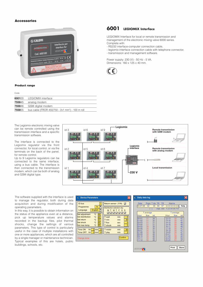
6001 LEGIOMIX Interface
LEGIOMIX Interface for local or remote transmission andmanagement of the electronic mixing valve 6000 series.Complete with:- RS232 interface-computer connection cable,- legiomix-interface connection cable with telephone connector,- transmission and management software.
Power supply: 230 (V) - 50 Hz - 5 VA.Dimensions: 160 x 125 x 40 mm.
The Legiomix electronic mixing valvecan be remote controlled using thetransmission interface and a specifictransmission software.
The interface is connected to theLegiomix regulator via the frontconnector, for local control, or via theterminals on the back of the panel,for remote control.Up to 9 Legiomix regulators can beconnected to the same interface,using a bus cable. The interface isthen connected to the transmissionmodem, which can be both of analogand GSM digital type.
id 1
id 2
id 3
id 4
id 5
id 6
id 7
id 8
id 9Legiomix
CALEFFI
Remote transmissionwith GSM modem
Legiomixinterface
Local transmission
Remote transmissionwith analog modem
OkMenuShock
Ok
Mixed °C Return °C
Martedi 13/02/2006
regolazionein corso
OkMenuShock
Ok
Mixed °C Return °C
Martedi 13/02/2006
regolazionein corso
OkMenuShock
Ok
Mixed °C Return °C
Martedi 13/02/2006
regolazionein corso
OkMenuShock
Ok
Mixed °C Return °C
Martedi 13/02/2006
regolazionein corso
OkMenuShock
Ok
Mixed °C Return °C
Martedi 13/02/2006
regolazionein corso
OkMenuShock
Ok
Mixed °C Return °C
Martedi 13/02/2006
regolazionein corso
OkMenuShock
Ok
Mixed °C Return °C
Martedi 13/02/2006
regolazionein corso
OkMenuShock
Ok
Mixed °C Return °C
Martedi 13/02/2006
regolazionein corso
OkMenuShock
Ok
Mixed °C Return °C
Martedi 13/02/2006
regolazionein corso
Parametri dispositivo
Change done
ID bus
Programme
Language English
50
60
57
60
65
Set adjustment
Set disinfection
Set return
Set shock
Set max temp.
1a
1 Return sensor (Y/N)
Disinfection selection day
M T W T F S S
T wait
T min
T flux
T shock
2
30
0
5
min
min
sec
min
T motor
T play
min
min
60
2
Confirm
Time ON
Time OFF
hh
hh
mm
mm
2
3
°C
°C
°C
°C
°C
0
0
Device Parameters Daily data log
Print Store
Help
Date Prgm T dis TR TR Alarms
max min 1 2 3 4 5 6 7 8
Hour flow ret
T.average
Hour flow ret
T.average
00-0101-0202-0303-0404-0505-0606-0707-0808-0909-1010-1111-12
515151515050525250505050
343231313030313646464646
12-1313-1414-1515-1616-1717-1818-1919-2020-2121-2222-2323-24
505050505050505051585851
474746464647474740425237
( ’ )
04-07-06 02 30 60 57 0 0 0 0 0 0 0 0
The software supplied with the interface is usedto manage the regulator, both during dataacquisition and during modification of theoperating parameters.In this way, it is possible to obtain information onthe status of the appliance even at a distance,pick up temperature values and alarmsrecorded in the backup files, pilot thermalshocks, change the settings of variousparameters. This type of control is particularlyuseful in the case of multiple installations withone or more appliances, which are all controlledby a single manager or maintenance technician.Typical examples of this are hotels, publicbuildings, schools, etc.
600100755845755846755855
LEGIOMIX interfaceanalog modemGSM digital modembus cable (FROR 450/750 - 2x1 mm2) - 100 m roll
Code

Code 600140Anti-scald device for domestic hot water use. 1/2” F inlet x 1/2” M outlet connections. Chrome plated brass body. Stainlesssteel springs. Maximum working pressure 10 bar. Set temperature 48°C ±1°C.
SPECIFICATION SUMMARIES
We reserve the right to change our products and their relevant technical data, contained in this publication, at any time and without prior notice.
CALEFFI S.P.A. · I · 28010 FONTANETO D’AGOGNA (NO) · S.R. 229, N.25 · TEL.INT. +39 0322 8491 R.A. · FAX +39 0322 863723· Http://www.caleffi.com · E-mail: [email protected] ·
© Copyright 2007 Calef f i S.P.A.
CALEFFI
Anti-scald device for domestic hot water use, code 600140
Function
The purpose of the device is to cut off the flow of water if its temperature reaches the set value.Designed for use in domestic hot water systems with electronic mixing valves with programmable thermal disinfection.Installed directly at the point of use outlet, it prevents the hot water from scalding the user during the thermal disinfectionperiod (T>50°C).
Safety in use
As shown in the diagram opposite, temperatures ofmore than 50°C can cause burning very quickly.For example, at 55°C partial burning will occur in
approximately 30 seconds, while at 60°C partial burning will occurin approximately 5 seconds. These times are, on average, halvedfor children and elderly people.
Depending on the type of system and its intended use, togetherwith the relevant risk assessment, various devices can beinstalled to safeguard users from scalding caused by hot tap water.
Technical Specifications
Materials: - body: brass EN 12164 CW614N, chrome plated- springs: stainless steel
Max working pressure (static): 10 barMax working pressure (dynamic): 5 barSet temperature: 48±1°C
Connections: 1/2” F inlet1/2” M outlet
Operation
Open Closed
CB
AA
Application diagram
HHyyddrraauulliicc cchhaarraacctteerriissttiiccss
Kv = 0,8 (m3/h)
Dimensions
Code A B C
600140 1/2” 8 38
Temperature - Exposure time
45
50
55
60
65
70
75°C
0,1 1 10 100 1.000 10.000 Seconds
Partial thicknessburns
Full thicknessburns
Safety conditions.Max. exposure time
at a specifictemperature