
130 series 01251/14 NA - Caleffi
9
01251/14 NA Balancing valve, fixed orifice 130 series Product range 130 series Fixed orifice balancing valve sizes 1/2”, 3/4”, 1”, 1 1/4”, 1 1/2”, and 2" NPT female CALEFFI Dimensions Technical specifications Materials Valve Body: low-lead brass Bonnet: low-lead brass Control stem: low-lead brass Valve plug: stainless steel Seal seat: brass Hydraulic seals: EPDM Stem guide bearing: PTFE Adjustment knob: PA6G30 Pressure test ports: low-lead brass body, EPDM seal elements Reduction of Lead in Drinking Water Act Compliant: 0.25% Max. weighted average lead content. Reduction of Lead in Drinking Water Act Certified by IAPMO R&T. Performance Suitable Fluids: water, glycol solutions Max. percentage of glycol: 50% Max. working pressure: 232 psi (16 bar) Working temperature range: -4 - 250°F (-20–120°C) Accuracy: ±10% Number of adjustment turns: 6 Threaded connections: 1/2”– 2" FNPT ACCREDITED ISO 9001 No. 000 ISO 9001 FM 21654 Function Caleffi 130 series low-lead brass manual balancing valves are used to measure and adjust the fluid flow rate in hydronic or plumbing circuits. The flow rate is directly determined from the pressure differential (from Venturi effect) measured across the two test ports. The valve design is “fixed orifice” with both pressure ports located upstream of adjustment plug and away from any pressure variations from turbulence as flow passes the adjustment plug – this feature makes pressure measurements and thus flow determination simpler and more accurate compared to “variable orifice” type balancing valves. Flow rate is calculated by simple formula or by easy reference to flow characteristic graph. Memory stop feature allows valve to be closed, and later reopened to the original set position. Teflon stem bearing guide prevents noise and vibration. The control stem threads remain dry at all times, and thus are not prone to seizing from scale after long in-operation periods. Stainless steel plug is highly resistant to erosion from fluid impurities. A DN25 PN20 150 A C B C o d e A B C W t ( l b ) 130 400A 1/2" 3" 4" 1 130 500A 3/4" 3 1/4" 4" 1.2 130 600A 1" 3 3/4" 4 1/4" 1.5 130 700A 1 1/4" 4 1/2" 4 1/2" 2 130 800A 1 1/2" 5" 4 3/4" 2.3 130 900A 2" 6" 5 1/4" 2.5
Transcript of 130 series 01251/14 NA - Caleffi

01251/14 NA
Balancing valve,fixed orifice
130 series
Product range
130 series Fixed orifice balancing valve sizes 1/2”, 3/4”, 1”, 1 1/4”, 1 1/2”, and 2" NPT female
CALEFFI
DimensionsTechnical specifications
MaterialsValve Body: low-lead brassBonnet: low-lead brassControl stem: low-lead brassValve plug: stainless steelSeal seat: brassHydraulic seals: EPDMStem guide bearing: PTFEAdjustment knob: PA6G30Pressure test ports: low-lead brass body, EPDM seal elementsReduction of Lead in Drinking Water Act Compliant: 0.25% Max. weighted average lead content. Reduction of Lead in Drinking Water Act Certified by IAPMO R&T. PerformanceSuitable Fluids: water, glycol solutionsMax. percentage of glycol: 50%Max. working pressure: 232 psi (16 bar)Working temperature range: -4 - 250°F (-20–120°C)Accuracy: ±10%Number of adjustment turns: 6Threaded connections: 1/2”– 2" FNPT
ACCREDITED
ISO 9001 No. 0003ISO 9001 FM 21654
Function
Caleffi 130 series low-lead brass manual balancing valves are used to measure and adjust the fluid flow rate in hydronic or plumbing circuits. The flow rate is directly determined from the pressure differential (from Venturi effect) measured across the two test ports. The valve design is “fixed orifice” with both pressure ports located upstream of adjustment plug and away from any pressure variations from turbulence as flow passes the adjustment plug – this feature makes pressure measurements and thus flow determination simpler and more accurate compared to “variable orifice” type balancing valves. Flow rate is calculated by simple formula or by easy reference to flow characteristic graph. Memory stop feature allows valve to be closed, and later reopened to the original set position. Teflon stem bearing guide prevents noise and vibration. The control stem threads remain dry at all times, and thus are not prone to seizing from scale after long in-operation periods. Stainless steel plug is highly resistant to erosion from fluid impurities.
A
DN25 PN20 150
A
C
B
Code A B C Wt (lb)
130400A 1/2" 3" 4" 1
130500A 3/4" 3 1/4" 4" 1.2
130600A 1" 3 3/4" 4 1/4" 1.5
130700A 1 1/4" 4 1/2" 4 1/2" 2
130800A 1 1/2" 5" 4 3/4" 2.3
130900A 2" 6" 5 1/4" 2.5

Advantages of balanced circuits
Balanced circuits have the following principal benefits:
1. In hydronic applications, the system emitters operate properly saving energy and providing greater comfort.2. In plumbing applications such as hot water recirculation, water is not wasted when there is a call for hot water from a fixture.3. Circuit pumps operate at maximum efficiency, reducing the risk of overheating and excessive wear.4. High fluid velocities which can result in noise, erosion and abrasion are avoided.5. The differential pressures acting on the circuit control valves are reduced preventing faulty operation.
Operating principle
The 130 series balancing valve is a hydraulic device that controls the flow rate of a fluid. Turning the knob moves a plug within the fluid stream which varies the flow rate. The flow rate is determined according to the pressure drop value measured by a differential pressure meter connected to the pressure test ports.
Construction details
Venturi flow rate measurement device
As shown in the figure below, the 130 series balancing valve contains two closely spaced pressure test ports located upstream of the valve plug and at different cross sectional areas. As fluid flows through the valve, the velocity at the port closest to the plug is greater than the velocity at the port furthest. The result, referred to as the Venturi effect, is an induced pressure differential across the ports.
Fast-coupling pressure test ports
The 130 series balancing valve has as standard probe type, fast-coupling pressure test ports. The probe from the differential pressure meter is inserted into the port packing, until the end of the probe enters the system. When the measuring probe is pulled out, the test port automatically closes, preventing fluid leakage. Care should be taken to pull the probe out slowly so as to allow adequate time for the packing to re-seal – otherwise fluid can quickly escape creating a hazardous situation. Consult differential pressure meter manufacturer instructions for proper use of instrument and pressure port couplings.
OPEN
CLOSE
RESET ON OFFBT OFF
Benefits:
1. Compared to variable orifice balancing valves, system balancing can be quicker. In variable orifice balancing valves, one pressure test port is located upstream and one downstream from the adjustment plug, so as the valve is adjusted, the flow coefficient of the orifice between the ports changes. Resultantly, to determine the flow rate, an added step of visually estimating the orifice Cv is required and introduces a factor of interpretation error in the balancing process leading to potentially less precise results.
Measuringprobe
Safetycap
Seal
2. With variable orifice balancing valves, in low flow applications requiring the valve to be closed more than 75% of full open, downstream turbulence can cause an unstable pressure reading signal which can result in measurement error. This effect is more pronounced if fluid impurities are present. With the 130 balancing valve with both ports upstream of the plug and away from turbulence effects, there is better pressure signal stability and thus less chance for pressure measurement error. There is also less sensitivity in the presence of fluid impurities.
OPEN
CLOSE
RESET ON OFFBT OFF
OPE
N
CLO
SE
RESE
TO
N O
FFBT
OFF

Adjustment knob
The shape of the knob is designed to ensure maximum comfort for the operator and an accurate adjustment. 6 full turns of rotation with 10 decimal graduations per rotation allows for precise valve adjust-ment. Shades of the scale indicator are large and clear allowing for easy, accurate reading. The knob is made of a reinforced high strength corrosion-resistant polymer.
Adjustment reference scale
Each 360° rotation of the knob moves the turn indicator by one position, ranging from 0 (valve closed) to 6 (valve fully open). A geared drive (6) allows for decimal graduations of the scale situated around the knob itself letting the flow rate to be finely tuned.
Stainless steel valve plug (1)
High resistance to corrosion and erosion due to continual water flow or impurities in fluid.
Teflon stem guide bearing (2)
Prevents noise and vibration - particularly in severe operating conditions.
4
2
3
1
5
Double internal o-rings
Double O-rings (3) prevent water from coming in contact with the screw thread (4), which allows the rod (5) to fine-tune the calibrated valve plug position (1). In addition, the resulting dry control stem thread prevents seizing from scale after long in-operation periods.
6
Memory stop
The 130 series balancing valve features a memory stop that allows the valve to be reopened to the initial position if it has been closed for any reason such as isolating components in the balanced circuit. Locking the position to be memorized requires the use of a 2.5 mm hex key.
Insulation shells
The 130 series balancing valve can be supplied with optional insulation shells, code CBN130xxxx series purchased separately, to minimize heat loss or eliminate condensation in chilled water applications.
ment. Shades of the scale indicator are large and clear allowing for
Code Size
CBN130400A Fits 1/2"
CBN130500A Fits 3/4"
CBN130600A Fits 1"
CBN130700A Fits 1 1/4"
CBN130800A Fits 1 1/2"
CBN130900A Fits 2"

Measuring the flow rate
Connect a differential pressure gauge to the pressure test ports of the venturi of the valve. Read the Δp value on the gauge, Knowing this differential pressure value and the flow coefficient of the Venturi orifice (which remains constant as valve knob is adjusted), the flow rate can be determined by either referencing the flow characteristic chart in the figure below or by using the formula:
G= Cv ×
where G is flow rate in gpm, Cv is the flow coefficient of the Venturi orifice, ∆p is the pressure differential in psi, and SG is the specific gravity of the fluid. For example, let’s assume water is the fluid medium and the balancing valve used is item 130500A (3/4”). We see from the Venturi chart the Cv value is 6.4. The specific gravity of water is 1.0. If the measured pressure differential is 0.3 psi, we can determine the flow rate G by substituting the values into the above formula: G=6.4√(0.3/1.0) = 3.5 gpm. Alternatively, using the Venturi chart below, if we plot where the 0.3 psi value intersects the ¾” graph, and drop a line vertically to where it intersects the gpm axis, we can estimate the value to be 3.5 gpm.
Setting the flow rate manually To manually adjust the flow rate through the valve, reposition the adjustment knob until the differential pressure indicated by the measuring device corresponds to the desired flow rate value on the Venturi chart for the valve being used. Or, calculate the pressure drop of the venturi using the following: G2Δp Venturi = Cv Venturi
2
Next, turn the adjustment knob until the theoretical Δp value calculated using the formula above is reached.
Correcting for fluids with a different density
This applies to fluids with viscosities of water and glycol mixtures or less. If using fluids with a specific gravity different from water at 70˚ F (20˚ C) (SG=1.0), correct the value of the pressure drop Δp measured using the following formula:
Δp' = Δp x (SG')
where: Δp' = reference pressure drop in psid (kPa) and SG' = non-water specific gravity.
Example: 50% propylene glycol has a specific gravity of 1.0366 at 70˚ F (20˚ C). To measure a flow rate of 3.5 gpm across the fixed venturi for a fluid with SG=1.0366, the pressure to read on the differential pressure metering device is calculated as Δp' = 0.3 x (1.0366) = 0.3108 psid.
ΔpSG
Venturi chart (water)
.03
.06
∆p G
(l/s)
(g
pm)
0.1
1
0.2
0.3
0.5
(psi) (bar)
10
2
3
5
20
0.01
0.1
0.02
0.03
0.05
1.0
0.2
0.3
0.5
0.4
4
0.04
0.4
.30
.50
1.4
2.8
5.6
10.2
0.5
2 5 10
20
50
100
200
.01
5
46.00
20.00
10.009.007.005.00
2.001.50
1.00
0.70
0.50
0.20
(feet of head)
0.05
3.00
0.30
0.11 0.003
0.005
7.0
12
.5.02
0.3
.10
.20
.70
3.5 gpm
1/2 “ 3/4“ 1“ 1 1/4“ 1 1/2“ 2“Valve size
Size CvVenturi
1/2" 3.25
3/4" 6.40
1" 11.20
1 1/4" 17.65
1 1/2" 23.80
2" 32.78
USING AND SETTING THE BALANCING VALVE

USING AND SETTING THE BALANCING VALVE
Presetting
The 130 series balancing valve features highly graduated adjustment which facilitates pre-setting. In commercial balancing applications where multiple balancing valves are used, significant labor time can be saved in the balancing process if in advance of being installed, the valves are pre-set to the expected knob position value. To pre-set, the anticipated pressure drop across the valve is required. For example, if balancing valve item 130500A (3/4”), water is the fluid, and it has been calculated that a pressure drop of 1.5 psi across the valve will result in a flow rate of 3.5 gpm in the circuit, we can see from the chart below that the knob value should be preset to a value between 2.5 and 3.0 with interpolation indicating approximately position 2.9.
.03
.06
∆p
G(l/
s)
(gpm
)
0.1
1
0.2
0.3
0.5
(psi) (bar)
10
2
3
5
20
0.01
0.1
0.02
0.03
0.05
1.0
0.2
0.3
0.5
0.4
4
0.04
0.4
.30
.50
1.4
2.8
5.6
10.2
0.5
2 5 10
20
50
10
0
20
0
.015
46.00
20.00
10.009.007.005.00
2.001.50
1.00
0.70
0.50
0.20
(feet of head)
0.05
3.00
0.30
0.11 0.003
0.005
7.0
12.5.02
0.3
.10
.20
.70
.5 1 1.5 2 2.5 33.5
4
4.5
56
Position
Cv Max
Size 1/2" 0.5 1 1.5 2 2.5 3 3.5 4 4.5 5 6
Cv .76 1.03 1.24 1.6 2.28 2.7 3.0 3.24 3.43 3.55 3.68
Position
Code 130400A 1/2 inch
.03
.06
∆p
G(l/
s)
(gpm
)
0.1
1
0.2
0.3
0.5
(psi) (bar)
10
2
3
5
20
0.01
0.1
0.02
0.03
0.05
1.0
0.2
0.3
0.5
0.4
4
0.04
0.4
.30
.50
1.4
2.8
5.6
10.2
0.5
2 5 10
20
50
10
0
20
0
.015
46.00
20.00
10.009.007.005.00
2.001.50
1.00
0.70
0.50
0.20
(feet of head)
0.05
3.00
0.30
0.11 0.003
0.005
7.0
12.5.02
0.3
.10
.20
.70
.5 1 1.5 2 2.5 33.5
4
4.5
56
3.5 gpm
1.5 psi
Position
Cv Max
Size 3/4" 0.5 1 1.5 2 2.5 3 3.5 4 4.5 5 6
Cv .85 1.1 1.32 1.83 2.53 3.23 3.85 4.33 4.6 4.82 5.19
Position
Code 130500A 3/4 inch
.03
.06
∆p
G(l/
s)
(gpm
)
0.1
1
0.2
0.3
0.5
(psi) (bar)
10
2
3
5
20
0.01
0.1
0.02
0.03
0.05
1.0
0.2
0.3
0.5
0.4
4
0.04
0.4
.30
.50
1.4
2.8
5.6
10.2
0.5
2 5 10
20
50
100
20
0
.01
5
46.00
20.00
10.009.007.005.00
2.001.50
1.00
0.70
0.50
0.20
(feet of head)
0.05
3.00
0.30
0.11 0.003
0.005
7.0
12
.5.02
0.3
.10
.20
.70
.5 1 1.5 2 2.5 33.5
4
4.5
56
Cv Max
Size 1" 0.5 1 1.5 2 2.5 3 3.5 4 4.5 5 6
Cv 1.08 1.38 1.76 2.4 3.0 3.83 4.5 5.36 6.15 7.1 8.87
Position
Position
Code 130600A 1 inch
.03
.06
∆p G
(l/s)
(g
pm)
0.1
1
0.2
0.3
0.5
(psi) (bar)
10
2
3
5
20
0.01
0.1
0.02
0.03
0.05
1.0
0.2
0.3
0.5
0.4
4
0.04
0.4
.30
.50
1.4
2.8
5.6
10.2
0.5
2 5 10 2 0 5 0 100
200
.015
46.00
20.00
10.009.007.005.00
2.001.50
1.00
0.70
0.50
0.20
(feet of head)
0.05
3.00
0.30
0.11 0.003
0.005
7.0
12.5.02
0.3
.10
.20
.70
Position
Cv Max
Size 1 1/4" 0.5 1 1.5 2 2.5 3 3.5 4 4.5 5 6
Cv 1.76 2.87 3.7 4.9 5.7 7.24 8.31 9.62 10.65 12.06 14.07
Position
.5 1 1.5 22.5 33.5
4
4.5
56
Code 130700A 1 1/4 inch

.03
.06
∆p
G(l/
s)
(gpm
)
0.1
1
0.2
0.3
0.5
(psi) (bar)
10
2
3
5
20
0.01
0.1
0.02
0.03
0.05
1.0
0.2
0.3
0.5
0.4
4
0.04
0.4
.30
.50
1.4
2.8
5.6
10.2
0.5
2 5 10
20
50
100
200
.01
5
46.00
20.00
10.009.007.005.00
2.001.50
1.00
0.70
0.50
0.20
(feet of head)
0.05
3.00
0.30
0.11 0.003
0.005
7.0
12
.5.02
0.3
.10
.20
.70
.5 1 1.5 2 2.5 33.5
4
4.5
56
Position
Cv Max
Size 1 1/2" 0.5 1 1.5 2 2.5 3 3.5 4 4.5 5 6
Cv 1.89 3.24 4.07 5.75 6.94 8.72 9.97 12.3 13.68 16.02 19.76
Position
Code 130800A 1 1/2 inch Code 130900A 2 inch
.03
.06
∆p
G(l/
s)
(gpm
)
0.1
1
0.2
0.3
0.5
(psi) (bar)
10
2
3
5
20
0.01
0.1
0.02
0.03
0.05
1.0
0.2
0.3
0.5
0.4
4
0.04
0.4
.30
.50
1.4
2.8
5.6
10.2
0.5
2 5 10
20
50
10
0
20
0
.015
46.00
20.00
10.009.007.005.00
2.001.50
1.00
0.70
0.50
0.20
(feet of head)
0.05
3.00
0.30
0.11 0.003
0.005
7.0
12.5.02
0.3
.10
.20
.70
Position .5 1 1.5 2 2.5 33.5
4
4.5
56
Cv Max
Size 2" 0.5 1 1.5 2 2.5 3 3.5 4 4.5 5 6
Cv 3.10 4.86 6.19 8.46 10.7 13.14 15.35 18.48 21.16 24.53 30.58
Position
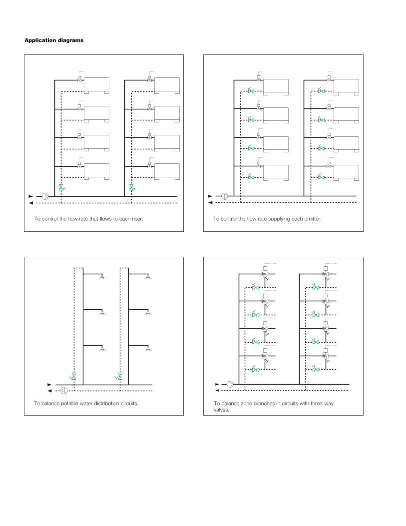
To balance zone branches in circuits with three-way valves.
To balance potable water distribution circuits.
Application diagrams
To control the flow rate that flows to each riser. To control the flow rate supplying each emitter.
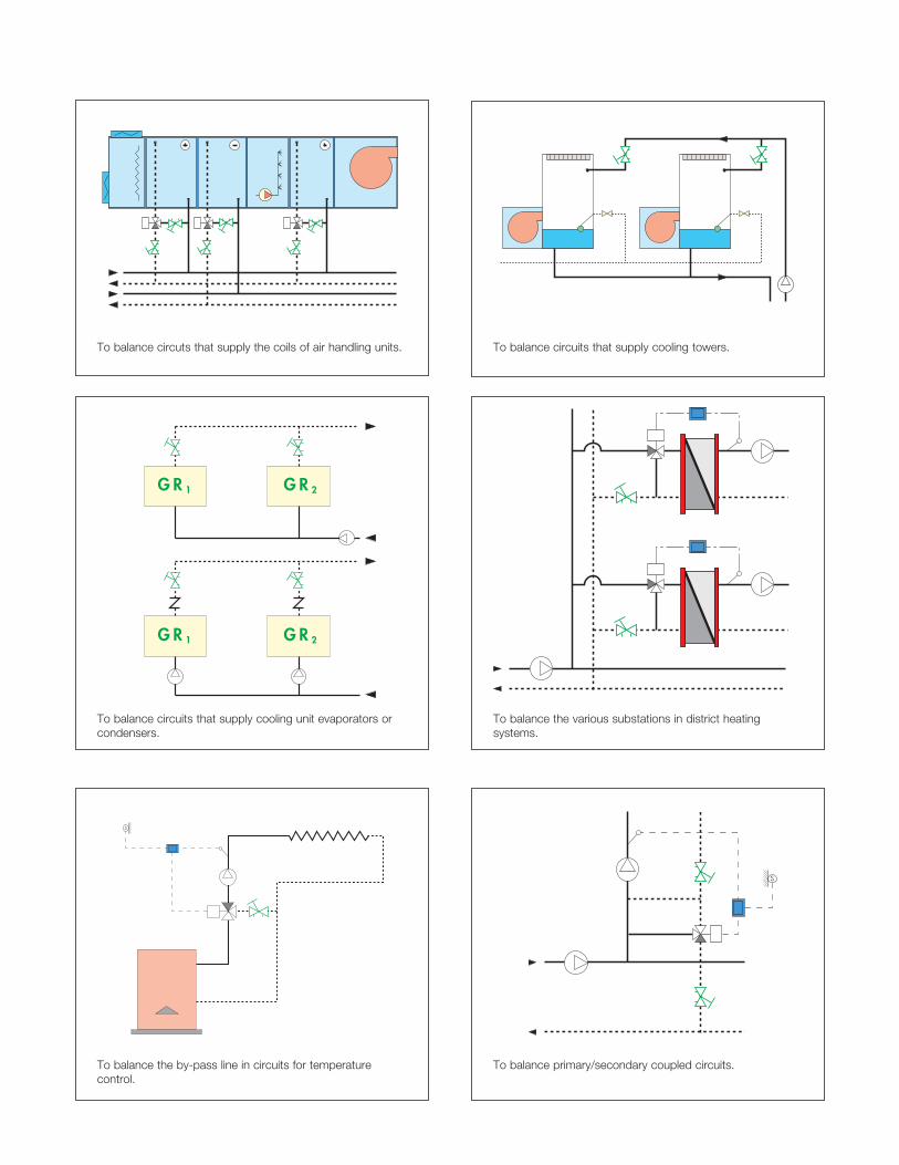
To balance circuts that supply the coils of air handling units. To balance circuits that supply cooling towers.
G R 1 G R 2
G R 1 G R 2
To balance circuits that supply cooling unit evaporators or condensers.
To balance the various substations in district heating systems.
s
To balance the by-pass line in circuits for temperature control.
s
To balance primary/secondary coupled circuits.

130 seriesBalancing valve with fixed (venturi) orifice. Threaded connections 1/2”, 3/4", 1", 1-1/4", 1-1/2", 2" NPT Female by Female. Low-lead brass body, bonnet and control stem (< 0.25% lead content) certified by IAPMO R&T. Stainless steel valve plug. PTFE stem guide bearing. Brass seal seat. EPDM hydraulic seals. PA6G30 adjusting knob with memory stop. Pressure test ports with low-lead brass body and EPDM seal elements. Water and glycol solutions. Maximum percentage of glycol 50%. Maximum working pressure 232 psi (16 bar). Working temperature range -4 to 250 deg F (-20 to 120°C). Number of adjustment turns: 6. Accuracy ± 10%. Pre-formed insulation shells available for field installation.
SPECIFICATION SUMMARIES
We reserve the right to change our products and their relevant technical data, contained in this publication, at any time and without prior notice.
Caleffi North America, Inc.3883 W. Milwaukee RoadMilwaukee, WI 53208Tel: 414-238-2360 · Fax: [email protected] · www.caleffi.com/usa/en-us© Copyright 2014 Caleffi North America, Inc.