Program 60-1165--Coupled and Series Epicyclic Gears
59
Program 60-1165--Coupled and Series Epicyclic Gears 1 Introduction A simple epicyclic gear unit consists of a central external gear (sun gear) meshed with one or more external gears (planet gears). The planet gears are then meshed with an internal gear (ring gear) which encloses the system. The planet gears and planet gear support bearings are held in a carrier which rotates about the geometric center of the unit. The term “epicyclic” comes from the path of a point on a planet gear which traces out an epicycloid in space. Therefore, there are three input/output/reaction elements in a simple epicyclic gear. The ring/sun ratio range for which these units can be designed with reasonable proportions is about 1.25:1 to 10:1. Below this range, the planet gears become quite small and it becomes difficult to design the gears and planet bearings for reasonable life. Above this range, the sun gear becomes small and the number of planets that can be used without interference is limited. This, again, makes the design of the bearings difficult. If more than one planet gear is used, the number of planets that will assemble between the sun and ring is limited by the numbers of teeth in the sun and ring and by the possibility of interference between the tips of the planet gear teeth. For a number of planets to assemble equally spaced around the center, the sum of the tooth numbers in the ring and sun divided by the number of planets used must be an integer: (Nring+Nsun)/np = integer where: Nring = Number of teeth in ring gear Nsun = Number of teeth in sun gear np = Number of planet gears The distance between the planet gear centers in the carrier must, of course, be greater than the outside diameter of the planet gears or tooth tip interference will result (assuming the planet gears are in the same plane). It is not necessary that the planets be equally spaced. However, to make assembly possible, they must be spaced at multiples of the “Least mesh angle.” ep/β = integer β = 360°/(Nring+Nsun) where: ep = Angle between adjacent planet gears, deg β = Least mesh angle, deg
Transcript of Program 60-1165--Coupled and Series Epicyclic Gears

Program 60-1165--Coupled and Series Epicyclic Gears
1
Introduction A simple epicyclic gear unit consists of a central external gear (sun gear) meshed with one or more external gears (planet gears). The planet gears are then meshed with an internal gear (ring gear) which encloses the system. The planet gears and planet gear support bearings are held in a carrier which rotates about the geometric center of the unit. The term “epicyclic” comes from the path of a point on a planet gear which traces out an epicycloid in space. Therefore, there are three input/output/reaction elements in a simple epicyclic gear. The ring/sun ratio range for which these units can be designed with reasonable proportions is about 1.25:1 to 10:1. Below this range, the planet gears become quite small and it becomes difficult to design the gears and planet bearings for reasonable life. Above this range, the sun gear becomes small and the number of planets that can be used without interference is limited. This, again, makes the design of the bearings difficult. If more than one planet gear is used, the number of planets that will assemble between the sun and ring is limited by the numbers of teeth in the sun and ring and by the possibility of interference between the tips of the planet gear teeth. For a number of planets to assemble equally spaced around the center, the sum of the tooth numbers in the ring and sun divided by the number of planets used must be an integer: (Nring+Nsun)/np = integer where: Nring = Number of teeth in ring gear Nsun = Number of teeth in sun gear np = Number of planet gears The distance between the planet gear centers in the carrier must, of course, be greater than the outside diameter of the planet gears or tooth tip interference will result (assuming the planet gears are in the same plane). It is not necessary that the planets be equally spaced. However, to make assembly possible, they must be spaced at multiples of the “Least mesh angle.” ep/β = integer β = 360°/(Nring+Nsun) where: ep = Angle between adjacent planet gears, deg β = Least mesh angle, deg

UTS Integrated Gear Software
2
For example, suppose we have an epicyclic set with Nring = 68 teeth and Nsun = 18 teeth and we wish to use 4 planets arranged 90° apart. (Nring+Nsun)/4 = 21.5 which is not an integer so we cannot arrange 4 planets 90° apart. (Nring+Nsun)/2 = 43 which is an integer so we can arrange 2 planets 180° apart. The least mesh angle, β = 360°/(Nring+Nsun) = 4.186°. When we attempt to place a planet 90° from the first planet, we find that we are at 90°/β = 21.5 least mesh angles and we cannot assemble. We can, however, place the planet at 21 or 22 least mesh angles. This would put the planet gear at 1/2 β or 2.093° from 90°. Then, since we know that 2 planets will assemble 180° apart, the 4 planets would be placed at 0°, 87.907°, 180° and 267.907°. The tip clearance should then be checked. Since we have two sets of planets 180° apart, the (theoretical) summation of the bearing loads on the sun and ring is still zero. The model will calculate the planet interference outside diameter for the planet. The planet OD must be less than this diameter. The planet tooth tip clearance will be the amount the actual planet OD is less than the interference OD. The summation of radial loads on the sun and ring will be made to determine whether or not the radial loads on the sun and planet are balanced. The result is displayed as a ”Yes” or “No” under “Radial Loads On Sun & Ring Balanced?”. It is not necessary (or even desirable) that Nring = Nsun + 2•Nplanet. If this relationship is met and the center distance is “standard,” then the operating pressure angles at the sun/planet external mesh, ∅ ext, and the planet/ring internal mesh, ∅ int, will be equal to the nominal pressure angle of the system. If ∅ ext is made higher than nominal and ∅ int lower than nominal, it will increase the strength of the set and reduce the burst stress on the ring. (A higher ∅ ext will also reduce or eliminate undercut on sun pinions with a small number of teeth if high addendum is added to the sun.) ∅ ext and ∅ int can be easily controlled by the number of planet teeth and the operating center distance. (If the ring gear rim thickness is 2 tooth depths or more, a high operating pressure angle will tend to reduce the bending stress. If the ring gear rim thickness is 1.5 tooth depths or less, a low operating pressure angle will tend to reduce the bending stress.) This model has been structured to analyze gear systems made up of two epicyclic gear sets coupled together or in series. This is done to extend the ratio range of a single set or to obtain a smaller and/or lighter system than can be designed with a single gear set. There are 36 different ways to connect the elements of two epicyclic sets together with one input, one output and one reaction. Connecting the sets in series with one input, one output and two reactions provides another 9 systems.

60-1165—Coupled and Series Epicyclic Gears
3
For the coupled systems, ASME Paper 68-MECH-45 is recommended as a reference. This excellent paper was written by P.W. Jensen, a consultant with Engineering Kinematics, Copenhagen, Denmark. Appendix 1 contains a listing of all possible connections for two coupled epicyclic sets. They are labeled from A1 to F6. (This labeling convention is the same as that used by Mr. Jensen in his paper.) For sets labeled A & E, the 1st stage carrier is the reaction member. For sets labeled B & C, the 1st stage ring gear is the reaction member. For sets labeled D & F, the 1st stage sun gear is the reaction member. (The reaction member is labeled “R.”) Two members of the 1st stage are always connected to two members of the 2nd stage. The possible speed ratio range for each system is listed with the members marked “X” or “Y” as the input or output members. The ratio ranges are for ring/sun ratios extending from about 1.25:1 to 10:1. (The ratio ranges can be extended beyond these limits if design problems do not prohibit lower or higher ring/sun ratios.) The ratios are positive if the system output turns in the same direction as the input and negative if the output turns in the opposite direction from the input. In some of the systems, the power is split between the stages and, in others, the power circulates between the stages. The split power systems usually will build in a smaller space or will be lighter than epicyclic series or simple offset systems. With circulating power, close attention must be paid to the tooth loads and the efficiency as the amount of power carried by the teeth can be many times the input power. Some of the systems have a twin with the same ratio range and efficiency although they are not connected the same way and do not have the same reaction member. (Mr. Jensen points out this remarkable fact in the reference paper.) The system label in parentheses () indicates the label for the twin, if any. Appendix 2 is a listing of all possible connections for two epicyclic sets in series. They are labeled with two letters. The label “A” indicates a star gear with a fixed carrier. The label “B” indicates a planetary gear with a fixed ring gear. The label “D” indicates a solar gear with a fixed sun gear. Therefore, the label “BA” indicates a planetary gear 1st stage and a star gear 2nd stage, for example. The ratio ranges are listed for the same ring/sun ratios as the coupled sets.

UTS Integrated Gear Software
4
Fig. 1
The image above shows the wizard data input form for this module. The user enters input ratio and number of planets, and makes other choices as shown with radio buttons. The application then selects the gear units that fit this data and displays diagrams of them, from which the user chooses. When the user selects a diagram, the application launches the Power User data input form, for further refinement of the model. This will be demonstrated in the example.

60-1165—Coupled and Series Epicyclic Gears
5
The pitch line velocity is calculated and the minimum recommended AGMA quality class is determined according to the ANSI/AGMA 6023-A88 Design Manual for Enclosed Epicyclic Gear Drives. The percent factorization is also calculated in accordance with ANSI/AGMA 6023-A88. See the standard for more information on factorized tooth numbers. The fundamental meshing frequency is displayed along with the expected primary torsional variation frequency. The model contains a table of K factors and Unit Loads for use in estimating the size of the gears required to carry the necessary load. The K factor is a function of the compressive stress carried on the teeth and is proportional to the square of the stress. The Unit Load is a function of the bending stress in the root area of the gears and is directly proportional to the stress. Both factors are directly proportional to the load. Different gear materials are, of course, capable of carrying different K and Unit Load factors for a given number of cycles. These factors are approximate because they do not contain many of the elements affecting the stresses on the gears. They are close enough, however, to allow us to get a “starting place” for our design with only the information at hand. It is essential, of course, to check our preliminary design with equations containing all the factors known to affect the operation and life of the gear set. The first thing we need to determine is a “service factor” which adjusts the load to account for the extra load imposed on the gears from non-uniform torques produced by the driver and driven machines. A few selected service factors are contained in the TK Solver table “SF,” Figure 2. The number of cycles we must run will be dealt with separately from the service factor and the service factors listed do not include adjustments for duration of service. Further information on service factors can be found in various AGMA standards pertaining to specific industries and applications. The service factors usually applied sometimes are not sufficient for critical drives running at high power and/or speed and must be used with caution. AGMA Standard 427, “AGMA Information Sheet, Systems Considerations for Critical Service Gear Drives” is an excellent source for information concerning the rating of these drives. The selection of the K factor and Unit Load is, of course, based on the material used for the gears and our best estimate of the load the gears will carry. The number of cycles the gears are required to run will also be part of the selection process.

UTS Integrated Gear Software
6
Fig. 2
The TK Solver table “KUL”, Figure 3, contains K factors and Unit Loads for a number of materials and conditions for steel gears. The table takes into account the class of gearing, such as high speed, medium speed, and so on. The accuracy to which the gears are made is also included along with the type of gear (spur, helical) and the heat treatment used. The unit loads have been adjusted for reverse bending of the planet gear teeth by reducing the unit loads usually used to 70% of the normal values. The table is “interactive” and we can change the items marked with an asterisk. The number of cycles needed is found by multiplying the speed (relative to the carrier) by the life required. (If the sun meshes with more than one planet this must be taken into account.) You may move the cursor to the appropriate location in the table and change the values for pinion cycles, service factor and ratio to suit the application. After solving the model the table will be updated to reflect the changed data.

60-1165—Coupled and Series Epicyclic Gears
7
Fig. 3

UTS Integrated Gear Software
8
Example As an example, we will do a preliminary design of a coupled epicyclic gear to drive a plastic roller from a small electric motor. The gear set will be inside the roller. Since, with this type of design, it is easy to seal the gear system, we will assume that the gears are permanently greased. The gears will be molded plastic. Under these conditions, a K factor of about 80 psi and a Unit Load of about 1000 psi should be satisfactory limits at least for preliminary design purposes. (See UTS Model 60-610 for information on plastic gear design.) The motor speed is 8000 RPM and a ratio of about 20 to 1 is required. The motor torque is 0.6 lbf-in. In the Independent Gear Software menu screen, drill down through “Epicyclic Gear Design” to the 60-1165 module and load the model. The form shown in Figure 1 will appear. Step 1
The only things we know about our gear set is that it will operate within a roller and the input ratio is 20. Beyond that, it might be same or opposite direction, with Member X or Member Y input, and coupled or series planetary type. Fortunately, the application permits you to examine all possible choices. You might first try the defaults. Enter the ratio input, 20, and click Enter. The application shows several choices. Eventually, you choose “Same Direction” for Member Input and Output, “Member Y” for Input, and “All” for Planetary Type. When you make these choices on the form, the application produces two choices, one of which is E3. This is the best choice for a gear set enclosed in a roller. Click on E3 to select it. The screen looks like Figure 4.

60-1165—Coupled and Series Epicyclic Gears
9
Fig. 4
Selecting “Smallest Diameter” will give us the smallest diameter for the ring gears. (In many cases, the “Smallest Diameter” ratio split between stages is the same as the “Minimum Total Weight” ratio split.)

UTS Integrated Gear Software
10
If one or two members are allowed to float radially, the load will be better shared between the planets. The model will use the following method to calculate the effective number of planets for load sharing calculations. 1 or 2 Members Floating: Number of Planets, #PL > 3: effPl = 1 + 0.9(#PL–1) Number of Planets, #PL <= 3: effPl = #PL All Members Fixed: Number of Planets, #PL > 8: effPl = 1 + 0.605(#PL–1) Number of Planets, #PL <= 8: #PL effPl 1 1 2 1.72 3 2.44 4 3 5 3.7 6 4.34 7 4.76 8 5.26 (Data for this table has been extracted from AGMA Standard 6023-A88, Design Manual for Enclosed Epicyclic Gear Drives with the permission of the publisher, American Gear Manufacturers Association, 1500 King Street, Alexandria, Virginia 22314.) Select “1 or 2 Members Floating” as the general design of the system will allow us to float the sun gear with no difficulty. Make the same selection for the 2nd stage. Finally, enter 3 planets. With 3 planets and floating sun gears, we will make maximum use of the material as the load sharing will be equal. (However, the system will build smaller with more than 3 planets even though the power will no longer be evenly split and the power per in3 of material will be lower.) Press Enter. The screen will display the Power User form, as shown in Figure 5.

60-1165—Coupled and Series Epicyclic Gears
11
Fig. 5
For the system to have the smallest possible ring gear diameter with 3 planets in each stage, the ring/sun ratios must be those shown, 2.083 for Stage 1 and 6.162 for Stage 2. Any other set of ratios, even though they produce the same overall ratio, will result in a larger diameter if the loading and aspect ratio limits are the same for both stages. Now that we have the target ratios for each stage, we will proceed with the detail design. We will take advantage of TK Solver’s ability to solve part of a model using only the data it has been given. We can then build our design a step at a time instead of having to use lengthy trial and error methods.

UTS Integrated Gear Software
12
Step 2
Click the “Gearing” tab on the Power User form. Enter 20 for the sun gear teeth as a starting point, then click the “Solve” button on the toolbar. The screen looks like Figure 6. Fig. 6
The application has warned us that the numbers of teeth for planet and ring gears are not integers. Specifically, the model calculates 10.833 and 41.667 for the planet and ring teeth to hold the ring/sun ratio of 2.0833. (The unrounded values can be seen on the TK Solver Variable Sheet.

60-1165—Coupled and Series Epicyclic Gears
13
It is desirable to keep a minimum of about 16 teeth in the planet gears, because fewer teeth may cause difficulties in the design of the external and internal meshes with the sun and the ring gear. Enter 30 for the sun gear teeth and solve. This gives us 16.25 and 62.5 for the planet and ring teeth. We could round the planet teeth to 16 but rounding the ring gear either way will move us quite a way away from our ideal ratio of 2.0833. Try 36 for the sun gear. This gives us 19.5 and 75 for the planet and ring teeth. This sun/ring ratio is exactly 2.0833. If we round the planet back to 19 teeth, it will give us just what we want. (In this case, we got the 2.0833 ratio exactly. This will not be the usual case. It is usually necessary to adjust both ring/sun ratios to obtain a satisfactory overall ratio. Note that the sum of the teeth in the sun and ring, 111, is divisible by the number of planets, 3. This will allow equal spacing of the planets.) Enter 19 for the planet gear, 75 for the ring gear, blank the Ring/Sun Ratio and solve. The form after solving is shown in Figure 7.

UTS Integrated Gear Software
14
Fig. 7
Step 3
Repeat the Step 2 sequence, this time for Stage 2. With a ring/sun ratio of 6.1622, the sun gear will be the smallest gear in the set. We will keep the sun gear at 12 teeth or more to avoid difficult undercut problems. Enter 12 for the sun gear teeth as a starting point and solve. Again, the application warns that the numbers of teeth for planet and ring gears are not integers. Specifically, they are 30.97 and 73.9, respectively, to hold the ring/ sun ratio of 6.1622.

60-1165—Coupled and Series Epicyclic Gears
15
Let’s see if we can get a closer ratio. Enter 13 for the sun gear and solve. This gives us 33.55 and 80.1 for the planet and ring teeth. We will assume that 13 and 80 are close enough, at least until we check the overall ratio. Enter 80 for the ring and 33 for the planet gear, blank the Ring/Sun Ratio and solve. (Note that the sum of the teeth in the sun and ring, 93, is divisible by the number of planets, 3. This will allow equal spacing of the planets.) This time the model solves successfully. The screen appears as shown in Figure 8. Fig. 8

UTS Integrated Gear Software
16
Step 4
On the System tab of the Power User form, enter the system input speed (8,000 rpm) and input torque (.6 lbf-in). Solve the model. The screen should appear as shown in Figure 9. Fig. 9
The Speed Ratio is shown with a rounded value of 20:1; the unrounded value is 19.974 to 1. We will assume that this ratio is close enough to 20 to 1 for this application. (If an exact ratio is necessary, it should be entered as an input value.) Report 1 shows the solved model with the data entered thus far.

60-1165—Coupled and Series Epicyclic Gears
17
Report 1
Model Title : Gears - Coupled and Series Epicyclic (Program 60-1165)
Project Name : UTS Project
Analysis Name : 1165 example
Unit System: US
Description Value Unit Comment
System Code (See PV) E3
Input member, 'X or 'Y Y
Input element(s) Sun2
Output element(s) "Rng1-Car2"
Fixed element(s) Car1
Coupling elements one "Sun1-Rng2"
Coupling elements two "Rng1-Car2"
Sum of system in^3
1st stage Sum Fd^2 (face*diameter^2) in^3
2nd stage Sum Fd^2 (face*diameter^2) in^3
Approx Efficiency (Gear losses only) 97.6 %
Plot operating pitch diameters? 'y/'n No
Input speed 8000.000 rpm
Output speed 400.513 rpm
Speed Ratio (Input/Output) 20
Inverse Speed Ratio (Output/Input) 0
Input torque 0.60 lbf-in
Output torque (no losses) -11.98 lbf-in
Input power 0 HP

UTS Integrated Gear Software
18
Model Title : Gears - Coupled and Series Epicyclic (Program 60-1165)
Project Name : UTS Project
Analysis Name : 1165 example
Unit System: US
Description Value Unit Comment
Output power (no losses) 0 HP
STAGE #1
Ring gear teeth 75
Planet gear teeth 19
Sun gear teeth 36
Ring/Sun Ratio 2.0833
Planet/Sun Ratio 0.5278
Ring/Planet Ratio 3.9474
PLANET SPACING
Least mesh angle 3 deg
NUMBER OF EQUALLY SPACED PLANETS
These are the 1st 4 up to 50 that
will assemble without interference -
planets will assemble equally if
(ring+sun)/planets=integer)
Number of planets 3
Not known
Effective planets - 1 member floating 3.00
Effective planets - All members fixed 2.44
Effective planets 3.00
Planet interference OD in
Sun & Ring Radial Loads Balanced?

60-1165—Coupled and Series Epicyclic Gears
19
Model Title : Gears - Coupled and Series Epicyclic (Program 60-1165)
Project Name : UTS Project
Analysis Name : 1165 example
Unit System: US
Description Value Unit Comment
Rotation speed
Sun gear -834.403 rpm
Ring gear 400.513 rpm
Carrier 0.000 rpm
Rotation speed relative to carrier
Sun gear -834.403 rpm
Ring gear 400.513 rpm
Planet gear 1580.974 rpm
Carrier 0.000 rpm
Pitch line velocity
Pitch line velocity ft/min
Max Recommended Spacing Tolerance in
Min Recommended AGMA Quality Class
Ring/Planet
Pitch line velocity ft/min
Max Recommended Spacing Tolerance in
Min Recommended AGMA Quality Class
Torque on elements (no losses)
Sun gear -3.69 lbf-in
Ring gear -7.69 lbf-in
Carrier 11.38 lbf-in

UTS Integrated Gear Software
20
Model Title : Gears - Coupled and Series Epicyclic (Program 60-1165)
Project Name : UTS Project
Analysis Name : 1165 example
Unit System: US
Description Value Unit Comment
Power (+ in, - out)(no losses)
Sun gear 0 HP
Sun % of total power 64 %
Ring gear 0 HP
Ring % of total power 64 %
Carrier 0 HP
Carrier % of total power 0 %
Coefficient of friction (Def=.06) 0.06
Approx power loss - Gears only 0 HP
Per planet gear
Relative power at sun mesh (no loss) 0 HP
Relative power at ring mesh (no loss) 0 HP
STAGE #2
Ring gear teeth 80
Planet gear teeth 33
Sun gear teeth 13
Ring/Sun Ratio 6.1538
Planet/Sun Ratio 2.5385
Ring/Planet Ratio 2.4242
PLANET SPACING
Least mesh angle 4 deg

60-1165—Coupled and Series Epicyclic Gears
21
Model Title : Gears - Coupled and Series Epicyclic (Program 60-1165)
Project Name : UTS Project
Analysis Name : 1165 example
Unit System: US
Description Value Unit Comment
NUMBER OF EQUALLY SPACED PLANETS
These are the 1st 4 up to 50 that
will assemble without interference -
planets will assemble equally if
(ring+sun)/planets=integer)
Number of planets 3
Not known
Effective planets - 1 member floating 3.00
Effective planets - All members fixed 2.44
Effective planets 3.00
Planet interference OD in
Sun & Ring Radial Loads Balanced?
Rotation speed
Sun gear 8000.000 rpm
Ring gear -834.403 rpm
Carrier 400.513 rpm
Rotation speed relative to carrier
Sun gear 7599.487 rpm
Ring gear -1234.917 rpm
Planet gear -2993.737 rpm
Carrier 0.000 rpm

UTS Integrated Gear Software
22
Model Title : Gears - Coupled and Series Epicyclic (Program 60-1165)
Project Name : UTS Project
Analysis Name : 1165 example
Unit System: US
Description Value Unit Comment
Ring/Planet
Pitch line velocity ft/min
Max Recommended Spacing Tolerance in
Min Recommended AGMA Quality Class
Sun gear 0.60 lbf-in
Ring gear 3.69 lbf-in
Carrier -4.29 lbf-in
Power (+ in, - out)(no losses)
Sun gear 0 HP
% of total power 100 %
Ring gear 0 HP
% of total power 64 %
Carrier 0 HP
% of total power 36 %
Coefficient of friction (Def=.06) 0.06
Approx power loss - Gears only 0 HP
Per planet gear
Relative power at sun mesh (no loss) 0 HP
Relative power at ring mesh (no loss) 0 HP

60-1165—Coupled and Series Epicyclic Gears
23
Now that the numbers of teeth have been selected we can begin to set the size of the unit to carry the required load.
Step 5
Return to the “Planet Loading” tab. Enter the maximum allowable K-Factor, 80 psi, for the 1st stage sun/planet mesh and same for the 2nd stage sun/planet mesh.
Step 6
We will use nominal 20 deg pressure angle spur gear teeth. In the nominal pitch-pressure angle section of the “Gearing” tab, enter 20 for the pressure angle and 0 for the helix angle. Make this entry for both Stage 1 and Stage 2, as shown in Figure 10. Fig. 10

UTS Integrated Gear Software
24
Step 7
Select the “Planet Loading” tab. Since the planet gear is smaller than the sun gear in stage 1, set the planet aspect ratio, “Planet gear face/PD,” to 1. For metal gears made to AGMA Q8 class and below, an aspect ratio of 1 is about the maximum to keep most all of the face in contact. For plastic gears, with a much lower modulus of elasticity and high “wearing in” effect, higher aspect ratios can be used. However, for this example, we will stay at one or below. In order to solve for diametral pitch and face width, it is necessary to make a guess for the face width and let TK Solver use an iterative method to get the answer. Toggle to the TK Solver Variable Sheet and enter a guess of 1 for the sun/planet face width, as shown in Figure 11. Fig. 11
Solve the model. Toggle back to the Power User form and click the Refresh Values button to insert the values from the TK Solver model in the form. Note that, in solving, we got no warning about the number of planets. This indicates that 3 planets will assemble equally spaced and the tips of the planet gear teeth will not interfere. If 3 planets would not assemble, it would be necessary to go back and change the number of teeth in the sun and ring so that the sum of the sun and ring was divisible by the number of planets and/or reduce the number of planets to eliminate tooth tip interference.

60-1165—Coupled and Series Epicyclic Gears
25
Step 8
Return to the “Gearing” tab and change the diametral pitch from 65.7 to 64 (in case a machined prototype is needed, we will use a “standard” diametral pitch). On the “Planet Loading” tab, blank the 1st stage planet aspect ratio. Solve the model. The data for the solved model to this point are shown in Report 2. Report 2
Model Title : Gears - Coupled and Series Epicyclic (Program 60-1165)
Project Name : UTS Project
Analysis Name :1165 example through step 7
Unit System: US
Description Value Unit Comment
System Code (See PV) E3
Input member, 'X or 'Y Y
Input element(s) Sun2
Output element(s) "Rng1-Car2"
Fixed element(s) Car1
Coupling elements one "Sun1-Rng2"
Coupling elements two "Rng1-Car2"
Sum of system in^3
1st stage Sum Fd^2 (face*diameter^2) in^3
2nd stage Sum Fd^2 (face*diameter^2) in^3
Approx Efficiency (Gear losses only) 97.6 %
Plot operating pitch diameters? 'y/'n No
Input speed 8000.000 rpm
Output speed 400.513 rpm

UTS Integrated Gear Software
26
Model Title : Gears - Coupled and Series Epicyclic (Program 60-1165)
Project Name : UTS Project
Analysis Name :1165 example through step 7
Unit System: US
Description Value Unit Comment
Speed Ratio (Input/Output) 20
Inverse Speed Ratio (Output/Input) 0
Input torque 0.60 lbf-in
Output torque (no losses) -11.98 lbf-in
Input power 0 HP
Output power (no losses) 0 HP
STAGE #1
Ring gear teeth 75
Planet gear teeth 19
Sun gear teeth 36
Ring/Sun Ratio 2.0833
Planet/Sun Ratio 0.5278
Ring/Planet Ratio 3.9474
CENTER DISTANCE & PRESSURE ANGLES
Operating center distance 0.434 in
Mid-point center distance 0.434 in
Opr press angle - Sun/Planet mesh 21.3731 deg
Opr press angle - Ring/Planet mesh 18.5298 deg
NOMINAL PITCH & PRESSURE ANGLE
Normal diametral pitch 64 1/in `
Normal pressure angle 20 deg
Helix angle 0 deg

60-1165—Coupled and Series Epicyclic Gears
27
Model Title : Gears - Coupled and Series Epicyclic (Program 60-1165)
Project Name : UTS Project
Analysis Name :1165 example through step 7
Unit System: US
Description Value Unit Comment
Transverse diametral pitch 64 1/in `
Transverse pressure angle 20 deg
Axial pitch _ in
Normal module 0 mm `
Transverse module 0 mm `
PLANET SPACING
Least mesh angle 3 deg
NUMBER OF EQUALLY SPACED PLANETS
These are the 1st 4 up to 50 that 3
will assemble without interference - #
planets will assemble equally if #
(ring+sun)/planets=integer) #
Number of planets 3
Not known _
Effective planets - 1 member floating 3.00
Effective planets - All members fixed 2.44
Effective planets 3.00
Planet interference OD 0.751 in
Sun & Ring Radial Loads Balanced? Yes
Rotation speed
Sun gear -834.403 rpm
Ring gear 400.513 rpm

UTS Integrated Gear Software
28
Model Title : Gears - Coupled and Series Epicyclic (Program 60-1165)
Project Name : UTS Project
Analysis Name :1165 example through step 7
Unit System: US
Description Value Unit Comment
Carrier 0.000 rpm
Rotation speed relative to carrier
Sun gear -834.403 rpm
Ring gear 400.513 rpm
Planet gear 1580.974 rpm
Carrier 0.000 rpm
Pitch line velocity
Pitch line velocity 123.99 ft/min
Max Recommended Spacing Tolerance 0.0027 in
Min Recommended AGMA Quality Class Q5
Ring/Planet
Pitch line velocity 121.78 ft/min
Max Recommended Spacing Tolerance 0.0037 in
Min Recommended AGMA Quality Class Q5
Torque on elements (no losses)
Sun gear -3.69 lbf-in
Ring gear -7.69 lbf-in
Carrier 11.38 lbf-in
Power (+ in, - out)(no losses)
Sun gear 0 HP
Sun % of total power 64 %

60-1165—Coupled and Series Epicyclic Gears
29
Model Title : Gears - Coupled and Series Epicyclic (Program 60-1165)
Project Name : UTS Project
Analysis Name :1165 example through step 7
Unit System: US
Description Value Unit Comment
Ring gear 0 HP
Ring % of total power 64 %
Carrier 0 HP
Carrier % of total power 0 %
Coefficient of friction (Def=.06) 0.06
Approx power loss - Gears only 0 HP
Per planet gear
Relative power at sun mesh (no loss) 0 HP
Relative power at ring mesh (no loss) 0 HP
Tooth tangential load at sun 4.34 lbf
Tooth tangential load at ring 4.42 lbf
Face width - sun/planet 0.28 in
K factor - sun/planet (See Table) 80.00 psi
Unit load - sun/planet (See Table) 1003.95 psi
Helical contact ratio - sun/planet _
Face width - planet/ring in
K factor - planet/ring (See Table) psi
Unit load - planet/ring (See Table) psi
Helical contact ratio - planet/ring _
Centripetal acceleration on planet 0.000 G's
OPERATING PITCH DIAMETERS
Ring gear 1.161 in

UTS Integrated Gear Software
30
Model Title : Gears - Coupled and Series Epicyclic (Program 60-1165)
Project Name : UTS Project
Analysis Name :1165 example through step 7
Unit System: US
Description Value Unit Comment
Planet with ring gear 0.294 in
Planet with sun gear 0.300 in
Sun gear 0.568 in
ASPECT RATIOS
Sun gear face/PD 0.49
Planet gear face/PD (Sun/Planet mesh) 0.92
VIBRATION
Fundamental meshing frequency 500.64 Hz
For equally spaced planets
% Factorized 100 %
% Non-factorized 0 %
Torsional variation frequency 1001.28 Hz
STAGE #2
Ring gear teeth 80
Planet gear teeth 33
Sun gear teeth 13
Ring/Sun Ratio 6.1538
Planet/Sun Ratio 2.5385
Ring/Planet Ratio 2.4242
CENTER DISTANCE & PRESSURE ANGLES
Operating center distance in

60-1165—Coupled and Series Epicyclic Gears
31
Model Title : Gears - Coupled and Series Epicyclic (Program 60-1165)
Project Name : UTS Project
Analysis Name :1165 example through step 7
Unit System: US
Description Value Unit Comment
Mid-point center distance in
Opr press angle - Sun/Planet mesh deg
Opr press angle - Ring/Planet mesh deg
NOMINAL PITCH & PRESSURE ANGLE
Normal diametral pitch 1/in `
Normal pressure angle 20 deg
Helix angle 0 deg
Transverse diametral pitch 1/in `
Transverse pressure angle 20 deg
Axial pitch _ in
Normal module mm `
Transverse module mm `
PLANET SPACING
Least mesh angle 4 deg
NUMBER OF EQUALLY SPACED PLANETS
These are the 1st 4 up to 50 that
will assemble without interference -
planets will assemble equally if
(ring+sun)/planets=integer)
Number of planets 3
Not known
Effective planets - 1 member floating 3.00

UTS Integrated Gear Software
32
Model Title : Gears - Coupled and Series Epicyclic (Program 60-1165)
Project Name : UTS Project
Analysis Name :1165 example through step 7
Unit System: US
Description Value Unit Comment
Effective planets - All members fixed 2.44
Effective planets 3.00
Planet interference OD in
Sun & Ring Radial Loads Balanced?
Rotation speed
Sun gear 8000.000 rpm
Ring gear -834.403 rpm
Carrier 400.513 rpm
Rotation speed relative to carrier
Sun gear 7599.487 rpm
Ring gear -1234.917 rpm
Planet gear -2993.737 rpm
Carrier 0.000 rpm
Sun/Planet
Pitch line velocity ft/min
Max Recommended Spacing Tolerance in
Min Recommended AGMA Quality Class
Ring/Planet
Pitch line velocity ft/min
Max Recommended Spacing Tolerance in
Min Recommended AGMA Quality Class
Sun gear 0.60 lbf-in

60-1165—Coupled and Series Epicyclic Gears
33
Model Title : Gears - Coupled and Series Epicyclic (Program 60-1165)
Project Name : UTS Project
Analysis Name :1165 example through step 7
Unit System: US
Description Value Unit Comment
Ring gear 3.69 lbf-in
Carrier -4.29 lbf-in
Power (+ in, - out)(no losses)
Sun gear 0 HP
% of total power 100 %
Ring gear 0 HP
% of total power 64 %
Carrier 0 HP
% of total power 36 %
Coefficient of friction (Def=.06) 0.06
Approx power loss - Gears only 0 HP
Per planet gear
Relative power at sun mesh (no loss) 0 HP
Relative power at ring mesh (no loss) 0 HP
Tooth tangential load at sun lbf
Tooth tangential load at ring lbf
Face width - sun/planet in
K factor - sun/planet (See Table) 80.00 psi
Unit load - sun/planet (See Table) psi
Helical contact ratio - sun/planet _
Face width - planet/ring in
K factor - planet/ring (See Table) psi
UTS Integrated Gear Software
34
Model Title : Gears - Coupled and Series Epicyclic (Program 60-1165)
Project Name : UTS Project
Analysis Name :1165 example through step 7
Unit System: US
Description Value Unit Comment
Unit load - planet/ring (See Table) psi
Helical contact ratio - planet/ring _
Centripetal acceleration on planet G's
OPERATING PITCH DIAMETERS
Ring gear in
Planet with ring gear in
Planet with sun gear in
Sun gear in
ASPECT RATIOS
Sun gear face/PD
Planet gear face/PD (Sun/Planet mesh)
VIBRATION
Fundamental meshing frequency 1646.56 Hz
For equally spaced planets
% Factorized %
% Non-factorized %
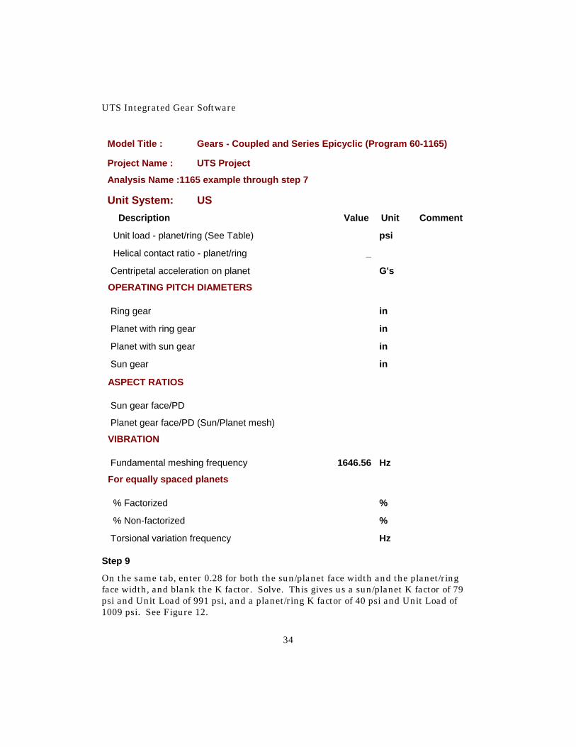
Torsional variation frequency Hz Step 9
On the same tab, enter 0.28 for both the sun/planet face width and the planet/ring face width, and blank the K factor. Solve. This gives us a sun/planet K factor of 79 psi and Unit Load of 991 psi, and a planet/ring K factor of 40 psi and Unit Load of 1009 psi. See Figure 12.

60-1165—Coupled and Series Epicyclic Gears
35
Fig. 12
Step 10
Since, for the 2nd stage, the sun gear is smaller than the planet gear, set the sun aspect ratio, “Sun gear face/PD,” to 1. Again, we will need to make a guess for the face width and let TK Solver use an iterative method to get the answer, as we did for the 1st stage. Enter a guess of 1 for the sun/planet face width, as shown in Figure 13. Solve the model. Note that, once again, we did not get a warning about the number of planets. (When you return to the Power User form, don’t forget to click the “Refresh Values” button.)

UTS Integrated Gear Software
36
Fig. 13
Step 11
On the “Gearing” tab, change the diametral pitch to 64 (since we are pretty close to this pitch, we will keep the 2nd stage pitch the same as the 1st stage). On the “Planet Loading” tab, blank the 2nd stage planet aspect ratio. Solve. This gives .81 for “Sun gear face/PD” and .32 for “Planet gear face/PD”. Step 12
Since we only have 13 teeth in the 2nd stage sun, we will increase the center distance above the “mid-point” center distance in order to allow some high addendum on the sun to avoid undercut. If we set the operating center distance to be “standard” for the ring and planet, we will probably have enough extended center distance to prevent undercut on the 13 tooth pinion. (There is no compelling reason to use a “standard” center distance but, with a planet that has been rounded down by 1/2 or 1 tooth, it usually works pretty well.) If this is not enough “spread” center distance to achieve a good tooth geometry, it will be necessary to further increase the center distance or remove another tooth from the planet gear.

60-1165—Coupled and Series Epicyclic Gears
37
On the TK Solver Variable Sheet, move the cursor to “Operating center distance” and type into the input column (80-33)/(2*pn2) and enter. TK will automatically calculate the value, as shown in Figure 14. This is the “standard” center distance for the ring and planet. Solve the model. (Note that after solving the ring/planet operating pressure angle is 20 degrees, the same as the nominal pressure angle.) Return to the Power User form and click “Refresh Values”. Fig. 14
Step 13
Enter 0.16 for both the sun/planet face width and the planet/ring face width. Blank the K factor. Solve. This gives us a K factor of 81 psi and a Unit Load of 771 psi for the sun/planet, and a K factor of 14 psi and Unit Load of 788 psi for the planet/ring. The model has now been completely solved. See Figure 15. Report 3 shows all the data for the solved model and includes plots of the operating pitch diameters of both stages.

UTS Integrated Gear Software
38
Fig. 15

60-1165—Coupled and Series Epicyclic Gears
39
Report 3
Model Title : Gears - Coupled and Series Epicyclic (Program 60-1165)
Project Name : UTS Project
Analysis Name :1165 example through step 13
Unit System: US
Description Value Unit Comment
System Code (See PV) E3
Input member, 'X or 'Y Y
Input element(s) Sun2
Output element(s) "Rng1-Car2"
Fixed element(s) Car1
Coupling elements one "Sun1-Rng2"
Coupling elements two "Rng1-Car2"
Sum of system 1 in^3
1st stage Sum Fd^2 (face*diameter^2) 0 in^3
2nd stage Sum Fd^2 (face*diameter^2) 0 in^3
Approx Efficiency (Gear losses only) 97.6 %
Plot operating pitch diameters? 'y/'n Yes
Input speed 8000.000 rpm
Output speed 400.513 rpm
Speed Ratio (Input/Output) 20
Inverse Speed Ratio (Output/Input) 0
Input torque 0.60 lbf-in
Output torque (no losses) -11.98 lbf-in
Input power 0 HP

UTS Integrated Gear Software
40
Model Title : Gears - Coupled and Series Epicyclic (Program 60-1165)
Project Name : UTS Project
Analysis Name :1165 example through step 13
Unit System: US
Description Value Unit Comment
Output power (no losses) 0 HP
STAGE #1
Ring gear teeth 75
Planet gear teeth 19
Sun gear teeth 36
Ring/Sun Ratio 2.0833
Planet/Sun Ratio 0.5278
Ring/Planet Ratio 3.9474
CENTER DISTANCE & PRESSURE ANGLES
Operating center distance 0.434 in
Mid-point center distance 0.434 in
Opr press angle - Sun/Planet mesh 21.3731 deg
Opr press angle - Ring/Planet mesh 18.5298 deg
NOMINAL PITCH & PRESSURE ANGLE
Normal diametral pitch 64 1/in `
Normal pressure angle 20 deg
Helix angle 0 deg
Transverse diametral pitch 64 1/in `
Transverse pressure angle 20 deg
Axial pitch _ in
Normal module 0 mm `
Transverse module 0 mm `

60-1165—Coupled and Series Epicyclic Gears
41
Model Title : Gears - Coupled and Series Epicyclic (Program 60-1165)
Project Name : UTS Project
Analysis Name :1165 example through step 13
Unit System: US
Description Value Unit Comment
PLANET SPACING
Least mesh angle 3 deg
NUMBER OF EQUALLY SPACED PLANETS
These are the 1st 4 up to 50 that 3
will assemble without interference - #
planets will assemble equally if #
(ring+sun)/planets=integer) #
Number of planets 3
Not known _
Effective planets - 1 member floating 3.00
Effective planets - All members fixed 2.44
Effective planets 3.00
Planet interference OD 0.751 in
Sun & Ring Radial Loads Balanced? Yes
Rotation speed
Sun gear -834.403 rpm
Ring gear 400.513 rpm
Carrier 0.000 rpm
Rotation speed relative to carrier
Sun gear -834.403 rpm
Ring gear 400.513 rpm
Planet gear 1580.974 rpm

UTS Integrated Gear Software
42
Model Title : Gears - Coupled and Series Epicyclic (Program 60-1165)
Project Name : UTS Project
Analysis Name :1165 example through step 13
Unit System: US
Description Value Unit Comment
Carrier 0.000 rpm
Pitch line velocity
Pitch line velocity 123.99 ft/min
Max Recommended Spacing Tolerance 0.0027 in
Min Recommended AGMA Quality Class Q5
Ring/Planet
Pitch line velocity 121.78 ft/min
Max Recommended Spacing Tolerance 0.0037 in
Min Recommended AGMA Quality Class Q5
Torque on elements (no losses)
Sun gear -3.69 lbf-in
Ring gear -7.69 lbf-in
Carrier 11.38 lbf-in
Power (+ in, - out)(no losses)
Sun gear 0 HP
Sun % of total power 64 %
Ring gear 0 HP
Ring % of total power 64 %
Carrier 0 HP
Carrier % of total power 0 %
Coefficient of friction (Def=.06) 0.06

60-1165—Coupled and Series Epicyclic Gears
43
Model Title : Gears - Coupled and Series Epicyclic (Program 60-1165)
Project Name : UTS Project
Analysis Name :1165 example through step 13
Unit System: US
Description Value Unit Comment
Approx power loss - Gears only 0 HP
Per planet gear
Relative power at sun mesh (no loss) 0 HP
Relative power at ring mesh (no loss) 0 HP
Tooth tangential load at sun 4.34 lbf
Tooth tangential load at ring 4.42 lbf
Face width - sun/planet 0.28 in
K factor - sun/planet (See Table) 78.99 psi
Unit load - sun/planet (See Table) 991.23 psi
Helical contact ratio - sun/planet _
Face width - planet/ring 0.28 in
K factor - planet/ring (See Table) 40.02 psi
Unit load - planet/ring (See Table) 1009.26 psi
Helical contact ratio - planet/ring _
Centripetal acceleration on planet 0.000 G's
OPERATING PITCH DIAMETERS
Ring gear 1.161 in
Planet with ring gear 0.294 in
Planet with sun gear 0.300 in
Sun gear 0.568 in
ASPECT RATIOS
Sun gear face/PD 0.49

UTS Integrated Gear Software
44
Model Title : Gears - Coupled and Series Epicyclic (Program 60-1165)
Project Name : UTS Project
Analysis Name :1165 example through step 13
Unit System: US
Description Value Unit Comment
Planet gear face/PD (Sun/Planet mesh) 0.93
VIBRATION
Fundamental meshing frequency 500.64 Hz
For equally spaced planets
% Factorized 100 %
% Non-factorized 0 %
Torsional variation frequency 1001.28 Hz
STAGE #2
Ring gear teeth 80
Planet gear teeth 33
Sun gear teeth 13
Ring/Sun Ratio 6.1538
Planet/Sun Ratio 2.5385
Ring/Planet Ratio 2.4242
CENTER DISTANCE & PRESSURE ANGLES
Operating center distance 0.367 in
Mid-point center distance 0.363 in
Opr press angle - Sun/Planet mesh 23.1179 deg
Opr press angle - Ring/Planet mesh 20.0000 deg
NOMINAL PITCH & PRESSURE ANGLE
Normal diametral pitch 64 1/in `

60-1165—Coupled and Series Epicyclic Gears
45
Model Title : Gears - Coupled and Series Epicyclic (Program 60-1165)
Project Name : UTS Project
Analysis Name :1165 example through step 13
Unit System: US
Description Value Unit Comment
Normal pressure angle 20 deg
Helix angle 0 deg
Transverse diametral pitch 64 1/in `
Transverse pressure angle 20 deg
Axial pitch _ in
Normal module 0 mm `
Transverse module 0 mm `
PLANET SPACING
Least mesh angle 4 deg
NUMBER OF EQUALLY SPACED PLANETS
These are the 1st 4 up to 50 that 3
will assemble without interference - #
planets will assemble equally if #
(ring+sun)/planets=integer) #
Number of planets 3
Not known _
Effective planets - 1 member floating 3.00
Effective planets - All members fixed 2.44
Effective planets 3.00
Planet interference OD 0.636 in
Sun & Ring Radial Loads Balanced? Yes

UTS Integrated Gear Software
46
Model Title : Gears - Coupled and Series Epicyclic (Program 60-1165)
Project Name : UTS Project
Analysis Name :1165 example through step 13
Unit System: US
Description Value Unit Comment
Rotation speed
Sun gear 8000.000 rpm
Ring gear -834.403 rpm
Carrier 400.513 rpm
Rotation speed relative to carrier
Sun gear 7599.487 rpm
Ring gear -1234.917 rpm
Planet gear -2993.737 rpm
Carrier 0.000 rpm
Sun/Planet
Pitch line velocity 412.91 ft/min
Max Recommended Spacing Tolerance 0.00162 in
Min Recommended AGMA Quality Class Q5
Ring/Planet
Pitch line velocity 404.13 ft/min
Max Recommended Spacing Tolerance 0.0022 in
Min Recommended AGMA Quality Class Q5
Sun gear 0.60 lbf-in
Ring gear 3.69 lbf-in
Carrier -4.29 lbf-in

60-1165—Coupled and Series Epicyclic Gears
47
Model Title : Gears - Coupled and Series Epicyclic (Program 60-1165)
Project Name : UTS Project
Analysis Name :1165 example through step 13
Unit System: US
Description Value Unit Comment
Power (+ in, - out)(no losses)
Sun gear 0 HP
% of total power 100 %
Ring gear 0 HP
% of total power 64 %
Carrier 0 HP
% of total power 36 %
Coefficient of friction (Def=.06) 0.06
Approx power loss - Gears only 0 HP
Per planet gear
Relative power at sun mesh (no loss) 0 HP
Relative power at ring mesh (no loss) 0 HP
Tooth tangential load at sun 1.93 lbf
Tooth tangential load at ring 1.97 lbf
Face width - sun/planet 0.16 in
K factor - sun/planet (See Table) 80.91 psi
Unit load - sun/planet (See Table) 770.93 psi
Helical contact ratio - sun/planet _
Face width - planet/ring 0.16 in
K factor - planet/ring (See Table) 14.02 psi
Unit load - planet/ring (See Table) 787.69 psi
Helical contact ratio - planet/ring _

UTS Integrated Gear Software
48
Model Title : Gears - Coupled and Series Epicyclic (Program 60-1165)
Project Name : UTS Project
Analysis Name :1165 example through step 13
Unit System: US
Description Value Unit Comment
Centripetal acceleration on planet 1.673 G's
OPERATING PITCH DIAMETERS
Ring gear 1.250 in
Planet with ring gear 0.516 in
Planet with sun gear 0.527 in
Sun gear 0.208 in
ASPECT RATIOS
Sun gear face/PD 0.77
Planet gear face/PD (Sun/Planet mesh) 0.30
VIBRATION
Fundamental meshing frequency 1646.56 Hz
For equally spaced planets
% Factorized 0 %
% Non-factorized 100 %
Torsional variation frequency 9879.33 Hz

60-1165—Coupled and Series Epicyclic Gears
49
1st Stage Operating Pitch Diameters

UTS Integrated Gear Software
50
2nd Stage Operating Pitch Diameters
The efficiency is about 97.6% with a coefficient of friction of 0.06 (this coefficient of friction is for a fully lubricated mesh) for both stages. (This is based on 1% loss at the sun/planet mesh with a 0.06 coefficient and 0.5% loss at the ring/planet mesh with a 0.06 coefficient. If the materials (along with the type of lubrication) have a different coefficient, enter the coefficient in the input column. Only the mesh losses are included.)
60-1165—Coupled and Series Epicyclic Gears
51
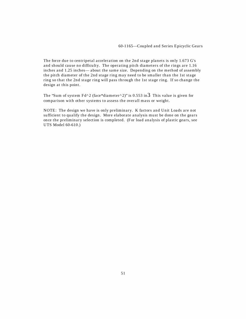
The force due to centripetal acceleration on the 2nd stage planets is only 1.673 G's and should cause no difficulty. The operating pitch diameters of the rings are 1.16 inches and 1.25 inches— about the same size. Depending on the method of assembly the pitch diameter of the 2nd stage ring may need to be smaller than the 1st stage ring so that the 2nd stage ring will pass through the 1st stage ring. If so change the design at this point. The “Sum of system Fd^2 (face*diameter^2)” is 0.553 in3. This value is given for comparison with other systems to assess the overall mass or weight. NOTE: The design we have is only preliminary. K factors and Unit Loads are not sufficient to qualify the design. More elaborate analysis must be done on the gears once the preliminary selection is completed. (For load analysis of plastic gears, see UTS Model 60-610.)

UTS Integrated Gear Software
52
Appendix 1

60-1165—Coupled and Series Epicyclic Gears
53

UTS Integrated Gear Software
54

60-1165—Coupled and Series Epicyclic Gears
55

UTS Integrated Gear Software
56

60-1165—Coupled and Series Epicyclic Gears
57

UTS Integrated Gear Software
58
Appendix 2

60-1165—Coupled and Series Epicyclic Gears
59