
EFFICIENZA E ANALISI TERMICA - Assiot · Epicyclic gears: AGMA 6123-B06 Bevel and hyoid gears:...
31
EFFICIENZA E ANALISI TERMICA Ing. Ivan Saltini Italy Country Manager
Transcript of EFFICIENZA E ANALISI TERMICA - Assiot · Epicyclic gears: AGMA 6123-B06 Bevel and hyoid gears:...

EFFICIENZA E ANALISI TERMICA
Ing. Ivan SaltiniItaly Country Manager

How to get most realistic efficiency calculation for gearboxes?

Topics
Motivation / general calculation
Automotive 7-speed dual clutch transmission
Drive cycle simulations
Efficiency optimization
Conclusion
Industrial bevel-helical gearbox

Motivation industrial gearboxes
Concept and design
High demands for power loss investigations
Systematic power loss analysis and optimization process
Power Loss Thermal ratingCooler
dimensioningOperating costs
Reduction of oil temperature
Dimensioning of cooler unit
Modification of housing design
Systematic power loss analysis and optimization process

Motivation automotive applications
KISSsys-model
Efficiency investigations as contribution to reach future CO2 limits
Systematic power loss analysis and optimization process
Power loss maps
Drive cycle simulation
Improvement measures
Efficiency evaluation
Comparison of different transmission layouts
Detection of power loss drivers
Evaluation of improvement measures in NEDC
Eff
icie
ncy
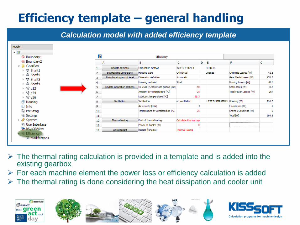
Efficiency template – general handling
The thermal rating calculation is provided in a template and is added into the existing gearbox
For each machine element the power loss or efficiency calculation is added
The thermal rating is done considering the heat dissipation and cooler unit
Calculation model with added efficiency template

Efficiency template – losses calculation
o Procedure
The template checks the model for machine elements
For the gears and bearings the losses calculation are added to the shaft editor
For the input and output shaft, the sealing losses can be added if required
Modified calculation

Efficiency template – losses calculation
o Gears
according to ISO/TR 14179-1/2
Epicyclic gears: AGMA 6123-B06
Bevel and hyoid gears: Niemann/Winter, Wech
o Alternative for ISO/TR 14179:
Contact analysis for meshing losses for cylindrical gears
Gear calculation
VZPVZV PPP 0

Efficiency template – losses calculation
o Bearings
o 𝑃𝑉 = 𝑃𝑉𝐿0 + 𝑃𝑉𝐿𝑃
according to ISO/TR 14179-1/2
according to SKF Catalog 1994
according to SKF Catalog 2004
3210 MMMMM
dragsealslrr MMMMM
Shaft calculation
Efficiency template – losses calculation
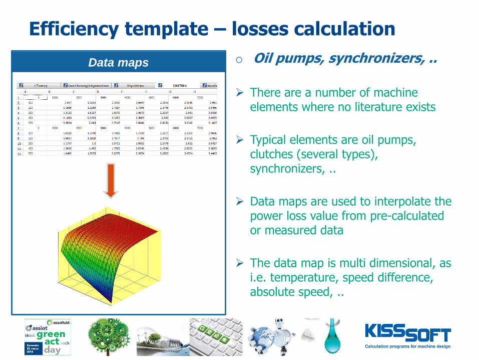
o Oil pumps, synchronizers, ..
There are a number of machine elements where no literature exists
Typical elements are oil pumps, clutches (several types), synchronizers, ..
Data maps are used to interpolate the power loss value from pre-calculated or measured data
The data map is multi dimensional, as i.e. temperature, speed difference, absolute speed, ..
Data maps
Eff
icie
ncy

Efficiency template – thermal rating
o Heat dissipation
The ISO/TR 14179-2 considers the gearbox housing design very detailed:
- housing, fins
- ventilation conditions
- input, output shafts and couplings
- foundation
o Thermal rating
The thermal rating is performed regarding:
- Calculate cooler capacity, or
- Calculate temperature
Calculation model

Motivation / general calculation
Automotive 7-speed dual clutch transmission
Drive cycle simulations
Efficiency optimization
Conclusion
Industrial bevel-helical gearbox
Topics

Industrial bevel-helical gearbox
standardized gearboxes series and customized gearbox design
Helical, bevel-helical and worm-helical gearboxes
Ratio up to about 200:1
High efficiency
Calculation model

Thermal rating – testing field
o Testing of power trains
Dynamic power measurement
Reporting of temperature and efficiency
Static functional testings as i.e. total stiffness of the power train
o Single components
Gear wheels
Separate testing field for bearings and radial shaft seals
Testing field

Thermal rating – measurement of power trains
o Testing of power trains for efficiency
Measurement series with constant torque and/or constant speed
Temperature profile for ambient air and oil are recorded
Input speed, torque and output torque (controlled) are recorded
Comparisons of temperature between calculations and measurements are ok, but modifications are necessary
Measurement reports

Calculation model - experiences
o Experiences with our customers are:
detailed and fast calculation procedure according to ISO/TR 14179-2
o Next steps are:
more validation with individual test runs of machine elements
Modification of temperature calculation to get closer match
Calculation model

Topics
Motivation / general calculation
Automotive 7-speed dual clutch transmission
Drive cycle simulations
Efficiency optimization
Conclusion
Industrial bevel-helical gearbox

7-speed dual clutch transmission (IAV 7-DC280)
CAD design with considered power losses
Sealings
Gear meshing
Gear speed dependent losses Injection Ventilation
Bearings Load dependent Load independent
Synchronizer Drag losses
Clutches Drag losses
Oil pump 3D map interpolation
Rotary unions Sealings under
pressure
Consideration of all relevant power losses in the transmission

Calculation model
o Benefit of calculation model
Calculation model considers all kinematic and kinetic interactions (7 speeds)
For the power losses, own data maps based on measurement or calculations were imported
Calculation model

Power loss maps instead of equations
Exemplary power losses of gear 7 at 60°C oil temperature
Data maps calculated for gear, bearing and sealing losses according to literature
Data maps calculated for other elements according to measurements or literature
0.0
0.5
1.0
1.5
2.0
2.5
3.0
50
0
15
00
25
00
35
00
45
00
55
00
Po
we
r lo
ss [
kW
]
Speed [rpm]
Power loss bearings
0.0
0.5
1.0
1.5
2.0
2.5
3.0
50
0
15
00
25
00
35
00
45
00
55
00
Po
we
r lo
ss [
kW
]
Speed [rpm]
Power loss gear meshing
0.0
0.1
0.1
0.2
0.2
0.3
0.3
0.4
50
0
15
00
25
00
35
00
45
00
55
00
Po
we
r lo
ss [
kW
]
Speed [rpm]
Power loss injection

Power loss maps
0
2
4
6
8
10
12
14
50
0
15
00
25
00
35
00
45
00
55
00
Po
we
r lo
ss [
kW
]
Speed [rpm]
Overall power loss
80%
85%
90%
95%
50
0
15
00
25
00
35
00
45
00
55
00
Speed [rpm]
Overall efficiency
Exemplary power losses of gear 7 at 60°C oil temperature

Topics
Motivation / general calculation
Automotive 7-speed dual clutch transmission
Drive cycle simulations
Efficiency optimization
Conclusion
Industrial bevel-helical gearbox

Drive cycle simulationso Simulation target
Evaluate the overall power loss distribution in the consumption relevant NEDC
Identification of power loss drivers and evaluate improvement measures directly on the basis of CO2 reduction predictions
o NEDC simulation environment
Mid size car with gasoline engine
Boundary conditions
0 500 1 103
0
1
2
3
Absoluter Verbrauch
2 103
4 103
6 103
8 103
100
0
100
200
Drehzahl [1/min]
Vol
llast
dreh
mom
ent [
Nm
]
Speed [rpm]
2000 4000
Torq
ue [N
m]
0
100
200
-1006000
300
Drive cycle NEDC
Vehicle medium-class
Drive train front transverse
Mass 1650 kg
Combustion engine gasoline
Power 140 kW
Torque 265 Nm
Operating points in engine map
time
ve
locity NEDC
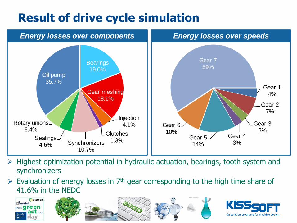
Result of drive cycle simulation
Bearings19.0%
Gear meshing18.1%
Injection4.1%
Clutches1.3%Synchronizers
10.7%
Sealings4.6%
Rotary unions6.4%
Oil pump35.7%
Gear 14%
Gear 27%
Gear 33%
Gear 43%
Gear 514%
Gear 610%
Gear 759%
Energy losses over components Energy losses over speeds
Highest optimization potential in hydraulic actuation, bearings, tooth system and synchronizers
Evaluation of energy losses in 7th gear corresponding to the high time share of 41.6% in the NEDC

Topics
Motivation / general calculation
Automotive 7-speed dual clutch transmission
Drive cycle simulations
Efficiency optimization
Conclusion
Industrial bevel-helical gearbox

Efficiency optimization
o Tooth system
Basic design exhibits a distribution between contact and overlap ratio of εα = 2 and εβ = 1
New design of macro geometry with decrease of profile contact ratio εα = 1.5 and increase of overlap contact ratio εβ = 1.5
o Bearings
Substitution of tapered roller bearing at differential with fixed/free bearing solution
Optimization measures regarding efficiency improvement

Efficiency optimization
Angle of rotation
Specifi
c s
lidin
g
Slid
e s
peed Gear A – Specific sliding
Gear B – Specific sliding
Slide speed
Pow
er
loss
No modification
Optimized
Norm
al f
orc
e (
line load)
Angle of rotation Angle of rotation
Efficiency optimization of gear micro geometry
Micro geometry (tip relief, crowning,…) gives further reduction of losses
Exemplary efficiency increase of the final drive from 99.06% without modifications up to 99.6% by low load conditions

Efficiency optimization
Efficiency Transmission error
10 % load
100 % load
Efficiency optimization using contact analysis
Automatic variation of modifications and load inside to obtain best variant
Assessment based on tooth contact analysis

Topics
Motivation / general calculation
Automotive 7-speed dual clutch transmission
Drive cycle simulations
Efficiency optimization
Conclusion
Industrial bevel-helical gearbox

How to get most realistic efficiency calculation:
The ISO/TR 14179 provides a good basis for calculation of power losses and thermal rating
However, for the power losses, meanwhile newer and more detailed literature are available, and also needed (i.e. for churning losses, etc.)
Instead of analytical approach, also contact analyses or data maps can be applied
The thermal rating is quite detailed, but requires some adjustment work for the individual gearbox
Energy losses over components

THANK YOU
FOR YOUR ATTENTION!