Program 60-108—Internal Gear Contact and Backlash 60-108—Internal Gear Contact And...
58
Program 60-108—Internal Gear Contact and Backlash 1 Introduction This is a model of the contact conditions between two internal spur or helical involute gears. The contact ratios, start of active profile, specific sliding and many other geometrical conditions are calculated and checked. In addition, the tooth thickness, center distance and backlash are calculated. The tooth thickness of gears is specified at the reference pitch diameter which is the diameter obtained by dividing the number of teeth by the transverse pitch (diametral pitch in the plane of rotation). The reference pitch diameters will be the same as the operating pitch diameters only if the gears are meshed at “standard” center distance. The “standard” center distance is one half the difference in the reference pitch diameters. The transverse backlash at the “standard” center distance will be the reference transverse circular pitch less the tooth thickness of both gears and would be a circular arc measurement along the reference pitch diameter. The operating pressure angle will be equal to the “nominal” pressure angle. When the gears are meshed on any other center distance the operating pitch diameters will not be the reference pitch diameters. The operating pressure angle will not be the “nominal” pressure angle. The transverse backlash will then be the operating circular pitch less the tooth thickness at the operating pitch diameters of both gears and would be a circular arc measurement along the operating pitch diameter. The change in reference pitch diameter tooth thickness calculated in the usual manner for high or low addendum gears operating on “non-standard” centers uses the “nominal” pressure angle of the gear as an approximation. Since the operating pressure angle changes with the center distance this introduces an error in the backlash calculated for these gear sets. If the center distance change from “standard” is extensive the error can be quite large. (The operating backlash will be smaller than anticipated whether the center distance is larger or smaller than “standard”. The amount will be equal to the “Basic transverse backlash”.) The model avoids this problem by using the “operating” dimensions of the gear set for these calculations after finding the operating pitch diameters.
Transcript of Program 60-108—Internal Gear Contact and Backlash 60-108—Internal Gear Contact And...

Program 60-108—Internal Gear Contact and Backlash
1
Introduction This is a model of the contact conditions between two internal spur or helical involute gears. The contact ratios, start of active profile, specific sliding and many other geometrical conditions are calculated and checked. In addition, the tooth thickness, center distance and backlash are calculated. The tooth thickness of gears is specified at the reference pitch diameter which is the diameter obtained by dividing the number of teeth by the transverse pitch (diametral pitch in the plane of rotation). The reference pitch diameters will be the same as the operating pitch diameters only if the gears are meshed at “standard” center distance. The “standard” center distance is one half the difference in the reference pitch diameters. The transverse backlash at the “standard” center distance will be the reference transverse circular pitch less the tooth thickness of both gears and would be a circular arc measurement along the reference pitch diameter. The operating pressure angle will be equal to the “nominal” pressure angle. When the gears are meshed on any other center distance the operating pitch diameters will not be the reference pitch diameters. The operating pressure angle will not be the “nominal” pressure angle. The transverse backlash will then be the operating circular pitch less the tooth thickness at the operating pitch diameters of both gears and would be a circular arc measurement along the operating pitch diameter. The change in reference pitch diameter tooth thickness calculated in the usual manner for high or low addendum gears operating on “non-standard” centers uses the “nominal” pressure angle of the gear as an approximation. Since the operating pressure angle changes with the center distance this introduces an error in the backlash calculated for these gear sets. If the center distance change from “standard” is extensive the error can be quite large. (The operating backlash will be smaller than anticipated whether the center distance is larger or smaller than “standard”. The amount will be equal to the “Basic transverse backlash”.) The model avoids this problem by using the “operating” dimensions of the gear set for these calculations after finding the operating pitch diameters.

UTS Integrated Gear Software
2
Caution Conditions:
The model checks many conditions to be sure that the gear set will function as intended. A number of geometry parameters that may cause problems or may be of interest are checked:
1. All Recess Action–All contact between teeth occurs past the operating pitch point of the set. This is a desirable condition if the sliding velocity is not too high at the end of action. The effective coefficient of friction is much lower in the recess action zone.
2. Approach Action Over 50%–There is more contact before the pitch point
than after the pitch point. This should be avoided as the teeth are approaching each other and the effective coefficient of friction may be higher in approach than in recess action for soft gear materials. More high addendum on the driver and/or low addendum on the driven will reduce approach action.
3. Total Contact Ratio Less than 1.2–A total contact ratio this low will
usually result in a gear set that is noisy and rough running. In spur gears the highest point of single tooth load will be near the tooth tip. Very little room is available for the application of tip relief.
4. Pinion: Possible Undercut in Root–There is a possibility of undercut in
the root area of the pinion. Without the cutting tool geometry, it is not possible to be sure that undercutting will occur but for “standard” cutting tools it is likely. This condition must be checked further (see UTS Models 60-410 and 60-450).
5. Specific Sliding Over 3–The ratio of sliding to rolling velocity between the
contacting flanks is over 3. This condition can cause wear, scoring and noisy operation - high specific sliding is more detrimental at higher pitch line velocities - specific sliding can usually be reduced by moving contact away from the base circle (center distance smaller than “standard”, high addendum, higher operating pressure angle).
6. Trochoidal Interference Between Gear ID and Pinion Tip–The path of
the tip of the pinion tooth interferes with the gear tooth tip at some point (usually outside of the line of action). A major cause of this condition is too little difference between the numbers of teeth in the pinion and gear.

60-108—Internal Gear Contact And Backlash
3
7. Gear ID Below Min–Involute Interference–The profile of the gear extends below the point of tangency of the line of action and the pinion base circle.
8. Contact Ratio Less than One–The gear set is not conjugate and is not
useable. The loaded tooth pair will drop the load before the next pair is in contact. The set may jam.
9. Negative Backlash Will Not Assemble–The total thickness of the gears
when assembled at the operating center distance is greater than the operating circular pitch. This will prevent assembly of the gears at the operating center distance.
10. Trans PA Negative Will Not Mesh–The center distance is too large for the
base circle diameters of the gears. The base circles are overlapping. It is not possible for gears to be conjugate under this condition.
11. Teeth Entered Not Integer–You have entered a non-integer for the
number of teeth in one or both of the gears. 12. Top Land Width–(normal tooth thickness at the tooth tip) is less than
0.275/Normal Diametral Pitch (or 0.275*Module). The tooth tip is quite pointed. If the gear is case hardened the tooth tip may be over hardened and brittle.
Because TK Solver allows partial solutions, you may investigate contact conditions directly in the TK Solver model as you add more and more data. For example, you might start like this to obtain a gear ratio: Enter: 17 for PINION, number of teeth 5.67 for Gear ratio Solve Output: 96.39 for GEAR, number of teeth The number of teeth must be an integer so: Enter: 96 for GEAR, number of teeth Blank: Gear ratio Solve Output: 5.647 for Gear ratio

UTS Integrated Gear Software
4
In this manner you can build a solution for the model as far as you wish. However, it is best to proceed until the CAUTION MESSAGE is blank, because of the number of conditions that are checked for problems. If desired, of course, a full set of data can be input and a solution obtained through the Integrated Gear Software interface.

60-108—Internal Gear Contact And Backlash
5
Examples Example 1 Example 1 is a helical gear set running on “standard” center distance. The outside diameter of the pinion and the inside diameter of the gear are “standard” for 10 normal diametral pitch. The tooth thickness has been adjusted to give about 0.01 inch backlash. Figure 1-1 is the data input form and Report 1-1 the inputs and outputs of a complete solution for this gear set. Fig. 1-1

UTS Integrated Gear Software
6
Report 1-1
Model Title : Program 60-108 Unit System: US CAUTION MESSAGE
CAUTION MESSAGE GEAR ID
BELOW MIN
INVOLUTE
INTERFER
PINION, number of teeth 17
GEAR, number of teeth 104
Driver: 'pin, 'gear pin
Pinion shaved or ground? ('s or 'g) no
Gear ratio 6.1176
NORMAL PLANE
Normal pitch 10.000000 1/in `
Normal pressure angle 14.500000 deg
Normal module 2.540000 mm `
Normal base pitch 0.3042 in
TRANSVERSE PLANE
Transverse pitch 8.1915 1/in `
Transverse pressure angle 17.5216 deg
Transverse module 3.1008 mm `
Transverse base pitch 0.3657 in

60-108—Internal Gear Contact And Backlash
7
Model Title : Program 60-108 Unit System: US COMMON
Helix angle 35.0000 deg
Base helix angle 33.7318 deg
Axial pitch 0.5477 in
Face width 1.1000 in
Operating center distance 5.3104 in
Standard center distance 5.3104 in
TOOTH THICKNESS & SPACE WIDTH PINION AT REF PD
Normal tooth thickness 0.1520 in
Transverse tooth thickness 0.1856 in
TOOTH THICKNESS & SPACE WIDTH PINION AT OD
Normal tooth thickness 0.0867 in
Transverse tooth thickness 0.1093 in
TOOTH THICKNESS & SPACE WIDTH GEAR AT REF PD
Normal tooth thickness 0.1520 in
Transverse tooth thickness 0.1856 in
Normal space width 0.1622 in
Transverse space width 0.1980 in
TOOTH THICKNESS & SPACE WIDTH GEAR AT ID
Normal tooth thickness 0.1036 in
Transverse tooth thickness 0.1258 in
CLEARANCE (FOR UNDERCUT CHECK)
Root clearance, Pinion (approx) 0.0250 in

UTS Integrated Gear Software
8
Model Title : Program 60-108 Unit System: US DIAMETERS PINION
Outside diameter 2.2753 in
Roll angle at OD 32.5035 deg
Reference pitch diameter 2.0753 in
Pointed tooth diameter 2.4499 in
Base diameter 1.9790 in
DIAMETERS GEAR
Inside diameter 12.4961 in
Roll angle at ID 14.6423 deg
Minimum ID (Involute Interference) 12.5222 in
Reference pitch diameter 12.6961 in
Pointed tooth diameter Below BD in
Base diameter 12.1070 in
OPERATING DATA
Working depth 0.2000 in
Basic transverse backlash 0.0000 in
Change in Opr CD from "Std" CD 0.0000 in
Normal backlash 0.0101 in
Transverse backlash 0.0124 in
Transverse pressure angle 17.5227 deg
Helix angle 35.0002 deg
Circular pitch 0.3835 in
Roll angle at pitch point 18.0902 deg

60-108—Internal Gear Contact And Backlash
9
Model Title : Program 60-108 Unit System: US OPERATING DATA PINION
Pitch diameter 2.0753 in
Transverse Tooth Thickness 0.1856 in
Start of active profile 1.9790 in
Roll angle at SAP 0.0000 deg
Normal tooth thickness at SAP 0.1635 in
Transverse tooth thickness at SAP 0.1965 in
OPERATING DATA GEAR
Pitch diameter 12.6961 in
Transverse Space Width 0.1979 in
Start of active profile 12.8548 in
Roll angle at SAP 20.4462 deg
Normal tooth thickness at SAP 0.1971 in
Transverse tooth thickness at SAP 0.2416 in
Trochoidal clearance: Pin OD/Gear ID 0.0458 in
OPERATING DATA CONTACT LENGTH
Length of contact, transverse plane 0.5613 in
Approach action 55.66 %
Recess action 44.34 %
OPERATING DATA CONTACT RATIOS
Profile 1.5349
Helical 2.0083
Total 3.5432

UTS Integrated Gear Software
10
Model Title : Program 60-108 Unit System: US OPERATING DATA LINES OF CONTACT ACROSS TEETH
Max total length 2.0327 in
Min total length 2.0272 in
Ratio: (Max length) / (Min length) 1.0027
SPECIFIC SLIDING RATIOS
Pinion start of active profile Too High
Pinion outside diameter 0.371
Gear start of active profile 0.590
Gear inside diameter 1.205
Coefficient of friction
Approx power loss %
Approx efficiency %
AGMA Load sharing ratio, mN 0.5426
AGMA I-factor for durability 0.316
This “standard” gear set would not be successful. There is involute interference because the gear profile extends below the point of tangency between the line of action and the base circle of the pinion. In addition, the specific sliding ratio is too high at the pinion “start of active profile” (SAP). Since the gear inside diameter is below the minimum to avoid involute interference (12.5222 inches) we will increase the gear ID to 12.525 inches to eliminate the interference. Report 1-2 shows the inputs and outputs after making this change and solving.

60-108—Internal Gear Contact And Backlash
11
Report 1-2
Model Title : Program 60-108 Unit System: US CAUTION MESSAGE
CAUTION MESSAGE PINION:
SPECIFIC
SLIDING
> THREE
PINION, number of teeth 17
GEAR, number of teeth 104
Driver: 'pin, 'gear pin
Pinion shaved or ground? ('s or 'g) no
Gear ratio 6.1176
NORMAL PLANE
Normal pitch 10.000000 1/in `
Normal pressure angle 14.500000 deg
Normal module 2.540000 mm `
Normal base pitch 0.3042 in
TRANSVERSE PLANE
Transverse pitch 8.1915 1/in `
Transverse pressure angle 17.5216 deg
Transverse module 3.1008 mm `
Transverse base pitch 0.3657 in

UTS Integrated Gear Software
12
Model Title : Program 60-108 Unit System: US COMMON
Helix angle 35.0000 deg
Base helix angle 33.7318 deg
Axial pitch 0.5477 in
Face width 1.1000 in
Operating center distance 5.3104 in
Standard center distance 5.3104 in
TOOTH THICKNESS & SPACE WIDTH PINION AT REF PD
Normal tooth thickness 0.1520 in
Transverse tooth thickness 0.1856 in
TOOTH THICKNESS & SPACE WIDTH PINION AT OD
Normal tooth thickness 0.0867 in
Transverse tooth thickness 0.1093 in
TOOTH THICKNESS & SPACE WIDTH GEAR AT REF PD
Normal tooth thickness 0.1520 in
Transverse tooth thickness 0.1856 in
Normal space width 0.1622 in
Transverse space width 0.1980 in
TOOTH THICKNESS & SPACE WIDTH GEAR AT ID
Normal tooth thickness 0.1099 in
Transverse tooth thickness 0.1336 in
CLEARANCE (FOR UNDERCUT CHECK)
Root clearance, Pinion (approx) 0.0250 in

60-108—Internal Gear Contact And Backlash
13
Model Title : Program 60-108 Unit System: US DIAMETERS PINION
Outside diameter 2.2753 in
Roll angle at OD 32.5035 deg
Reference pitch diameter 2.0753 in
Pointed tooth diameter 2.4499 in
Base diameter 1.9790 in
DIAMETERS GEAR
Inside diameter 12.5250 in
Roll angle at ID 15.1853 deg
Minimum ID (Involute Interference) 12.5222 in
Reference pitch diameter 12.6961 in
Pointed tooth diameter Below BD in
Base diameter 12.1070 in
OPERATING DATA
Working depth 0.1855 in
Basic transverse backlash 0.0000 in
Change in Opr CD from "Std" CD 0.0000 in
Normal backlash 0.0101 in
Transverse backlash 0.0124 in
Transverse pressure angle 17.5227 deg
Helix angle 35.0002 deg
Circular pitch 0.3835 in
Roll angle at pitch point 18.0902 deg

UTS Integrated Gear Software
14
Model Title : Program 60-108 Unit System: US OPERATING DATA PINION
Pitch diameter 2.0753 in
Transverse Tooth Thickness 0.1856 in
Start of active profile 1.9791 in
Roll angle at SAP 0.3189 deg
Normal tooth thickness at SAP 0.1635 in
Transverse tooth thickness at SAP 0.1966 in
OPERATING DATA GEAR
Pitch diameter 12.6961 in
Transverse Space Width 0.1979 in
Start of active profile 12.8548 in
Roll angle at SAP 20.4462 deg
Normal tooth thickness at SAP 0.1971 in
Transverse tooth thickness at SAP 0.2416 in
Trochoidal clearance: Pin OD/Gear ID 0.0410 in
OPERATING DATA CONTACT LENGTH
Length of contact, transverse plane 0.5558 in
Approach action 55.22 %
Recess action 44.78 %
OPERATING DATA CONTACT RATIOS
Profile 1.5198
Helical 2.0083
Total 3.5282

60-108—Internal Gear Contact And Backlash
15
Model Title : Program 60-108 Unit System: US OPERATING DATA LINES OF CONTACT ACROSS TEETH
Max total length 2.0129 in
Min total length 2.0074 in
Ratio: (Max length) / (Min length) 1.0027
SPECIFIC SLIDING RATIOS
Pinion start of active profile 46.616
Pinion outside diameter 0.371
Gear start of active profile 0.590
Gear inside diameter 0.979
Coefficient of friction
Approx power loss %
Approx efficiency %
AGMA Load sharing ratio, mN 0.5480
AGMA I-factor for durability 0.341 We still have some problems with this gear set. The specific sliding ratio is very high, 46.6, at the pinion SAP. The roll angle on the pinion at the start of action is less than 1 degree. Operation this close to the base circle is the cause of the high specific sliding ratio. In addition, it is very difficult to produce and measure an involute profile this close to the base circle as the radius of curvature is very small. The set also has more approach action than recess action. To illustrate one method of improving the gear set we will take the existing solution and modify it to obtain a full recess action gear set. (It is not necessary to modify the gear set to this extent to correct the existing problems but a full recess action set is sometimes desirable and as an example we will make this modification. Keep in mind that the pinion is driving and this solution would not be advisable if the gear were driving.)

UTS Integrated Gear Software
16
To make these changes we must use the Power User form. Since the outside diameter of the pinion and the inside diameter of the gear must be changed, the first step is to change the ID of the gear. The ID of the driven gear must be equal to the operating pitch diameter to insure that all tooth action must take place past the pitch point. On the “Common Data” tab of the Power User form, enter the operating pitch diameter of the gear as the ID of the gear. Blank the value for the OD of the pinion, as this is the value we are solving for. Next, on the “Operating Data” tab of the form, enter 0.2 inch for the working depth to maintain a full tooth depth design. (The working depth for “standard” full depth is equal to 2/NDP.) And on the “Clearance” tab of the form, blank the values of the tooth thickness for both gears. We will set the tooth thickness after we have established the outside diameter. Also on this tab, enter .06 for the coefficient of friction. Report 1-3 is the model after solving. Report 1-3
Model Title : Program 60-108 Unit System: US CAUTION MESSAGE
CAUTION MESSAGE
PINION, number of teeth 17
GEAR, number of teeth 104
Driver: 'pin, 'gear pin
Pinion shaved or ground? ('s or 'g) no
Gear ratio 6.1176

60-108—Internal Gear Contact And Backlash
17
Model Title : Program 60-108 Unit System: US NORMAL PLANE
Normal pitch 10.000000 1/in `
Normal pressure angle 14.500000 deg
Normal module 2.540000 mm `
Normal base pitch 0.3042 in
TRANSVERSE PLANE
Transverse pitch 8.1915 1/in `
Transverse pressure angle 17.5216 deg
Transverse module 3.1008 mm `
Transverse base pitch 0.3657 in
COMMON
Helix angle 35.0000 deg
Base helix angle 33.7318 deg
Axial pitch 0.5477 in
Face width 1.1000 in
Operating center distance 5.3104 in
Standard center distance 5.3104 in
TOOTH THICKNESS & SPACE WIDTH PINION AT REF PD
Normal tooth thickness in
Transverse tooth thickness in
TOOTH THICKNESS & SPACE WIDTH PINION AT OD
Normal tooth thickness in
Transverse tooth thickness in

UTS Integrated Gear Software
18
Model Title : Program 60-108 Unit System: US TOOTH THICKNESS & SPACE WIDTH GEAR AT REF PD
Normal tooth thickness in
Transverse tooth thickness in
Normal space width in
Transverse space width in
TOOTH THICKNESS & SPACE WIDTH GEAR AT ID
Normal tooth thickness in
Transverse tooth thickness in
CLEARANCE (FOR UNDERCUT CHECK)
Root clearance, Pinion (approx) 0.0250 in
DIAMETERS PINION
Outside diameter 2.4753 in
Roll angle at OD 43.0448 deg
Reference pitch diameter 2.0753 in
Pointed tooth diameter in
Base diameter 1.9790 in
DIAMETERS GEAR
Inside diameter 12.6961 in
Roll angle at ID 18.0898 deg
Minimum ID (Involute Interference) 12.5222 in
Reference pitch diameter 12.6961 in
Pointed tooth diameter in
Base diameter 12.1070 in

60-108—Internal Gear Contact And Backlash
19
Model Title : Program 60-108 Unit System: US OPERATING DATA
Working depth 0.2000 in
Basic transverse backlash 0.0000 in
Change in Opr CD from "Std" CD 0.0000 in
Normal backlash in
Transverse backlash in
Transverse pressure angle 17.5227 deg
Helix angle 35.0002 deg
Circular pitch 0.3835 in
Roll angle at pitch point 18.0902 deg
OPERATING DATA PINION
Pitch diameter 2.0753 in
Transverse Tooth Thickness in
Start of active profile 2.0753 in
Roll angle at SAP 18.0875 deg
Normal tooth thickness at SAP in
Transverse tooth thickness at SAP in
OPERATING DATA GEAR
Pitch diameter 12.6961 in
Transverse Space Width in
Start of active profile 12.9817 in
Roll angle at SAP 22.1693 deg
Normal tooth thickness at SAP in
Transverse tooth thickness at SAP in

UTS Integrated Gear Software
20
Model Title : Program 60-108 Unit System: US Trochoidal clearance: Pin OD/Gear ID 0.0239 in
OPERATING DATA CONTACT LENGTH
Length of contact, transverse plane 0.4310 in
Approach action 0.01 %
Recess action 99.99 %
OPERATING DATA CONTACT RATIOS
Profile 1.1785
Helical 2.0083
Total 3.1869
OPERATING DATA LINES OF CONTACT ACROSS TEETH
Max total length 1.5633 in
Min total length 1.5579 in
Ratio: (Max length) / (Min length) 1.0035
SPECIFIC SLIDING RATIOS
Pinion start of active profile 0.000
Pinion outside diameter 0.485
Gear start of active profile 0.942
Gear inside diameter 0.000
Coefficient of friction 0.0600
Approx power loss 0.72 %
Approx efficiency 99.28 %
AGMA Load sharing ratio, mN 0.7061
AGMA I-factor for durability 0.507

60-108—Internal Gear Contact And Backlash
21
This set looks pretty good. The maximum specific sliding ratio is only about 0.94 at the gear SAP (gear root). The roll angle of the pinion SAP is well away from the base circle at 18 degrees. The I-factor (contact stress factor) has increased from 0.341 to 0.507 which represents a large decrease in contact stress. Note that with a coefficient of friction of .06, the efficiency is about 99.28%. The efficiency is calculated in accordance with the methods in Chapter 12 of Dudley's Gear Handbook, 2nd Edition, by E.E. Shipley, published by McGraw-Hill. Now we need to address the tooth thickness and backlash of the new gear set. We will keep the backlash the same as in the original set. Again in the Power User form, enter 0.0101 inch for the normal backlash. We know that the top land (normal tooth thickness at the outside diameter) of the pinion will probably be less than the gear. We will set the pinion top land to 0.275/NDP. Enter 0.0275 inch for the tooth thickness at the OD of the pinion. The solved model is shown in Report 1-4. Report 1-4
Model Title : Program 60-108 Unit System: US
CAUTION MESSAGE
CAUTION MESSAGE None
PINION, number of teeth 17
GEAR, number of teeth 104
Driver: 'pin, 'gear pin

UTS Integrated Gear Software
22
Model Title : Program 60-108 Unit System: US Pinion shaved or ground? ('s or 'g) no
Gear ratio 6.1176
NORMAL PLANE
Normal pitch 10.000000 1/in `
Normal pressure angle 14.500000 deg
Normal module 2.540000 mm `
Normal base pitch 0.3042 in
TRANSVERSE PLANE
Transverse pitch 8.1915 1/in `
Transverse pressure angle 17.5216 deg
Transverse module 3.1008 mm `
Transverse base pitch 0.3657 in
COMMON
Helix angle 35.0000 deg
Base helix angle 33.7318 deg
Axial pitch 0.5477 in
Face width 1.1000 in
Operating center distance 5.3104 in
Standard center distance 5.3104 in
TOOTH THICKNESS & SPACE WIDTH PINION AT REF PD
Normal tooth thickness 0.1896 in
Transverse tooth thickness 0.2315 in

60-108—Internal Gear Contact And Backlash
23
Model Title : Program 60-108 Unit System: US TOOTH THICKNESS & SPACE WIDTH PINION AT OD
Normal tooth thickness 0.0275 in
Transverse tooth thickness 0.0358 in
TOOTH THICKNESS & SPACE WIDTH GEAR AT REF PD
Normal tooth thickness 0.1144 in
Transverse tooth thickness 0.1397 in
Normal space width 0.1997 in
Transverse space width 0.2438 in
TOOTH THICKNESS & SPACE WIDTH GEAR AT ID
Normal tooth thickness 0.1145 in
Transverse tooth thickness 0.1397 in
CLEARANCE (FOR UNDERCUT CHECK)
Root clearance, Pinion (approx) 0.0250 in
DIAMETERS PINION
Outside diameter 2.4753 in
Roll angle at OD 43.0448 deg
Reference pitch diameter 2.0753 in
Pointed tooth diameter 2.5222 in
Base diameter 1.9790 in
DIAMETERS GEAR
Inside diameter 12.6961 in
Roll angle at ID 18.0898 deg

UTS Integrated Gear Software
24
Model Title : Program 60-108 Unit System: US Minimum ID (Involute Interference) 12.5222 in
Reference pitch diameter 12.6961 in
Pointed tooth diameter Below BD in
Base diameter 12.1070 in
OPERATING DATA
Working depth 0.2000 in
Basic transverse backlash 0.0000 in
Change in Opr CD from "Std" CD 0.0000 in
Normal backlash 0.0101 in
Transverse backlash 0.0123 in
Transverse pressure angle 17.5227 deg
Helix angle 35.0002 deg
Circular pitch 0.3835 in
Roll angle at pitch point 18.0902 deg
OPERATING DATA PINION
Pitch diameter 2.0753 in
Transverse Tooth Thickness 0.2315 in
Start of active profile 2.0753 in
Roll angle at SAP 18.0875 deg
Normal tooth thickness at SAP 0.1896 in
Transverse tooth thickness at SAP 0.2315 in
OPERATING DATA GEAR
Pitch diameter 12.6961 in
Transverse Space Width 0.2438 in

60-108—Internal Gear Contact And Backlash
25
Model Title : Program 60-108 Unit System: US Start of active profile 12.9817 in
Roll angle at SAP 22.1693 deg
Normal tooth thickness at SAP 0.1989 in
Transverse tooth thickness at SAP 0.2446 in
Trochoidal clearance: Pin OD/Gear ID 0.0239 in
OPERATING DATA CONTACT LENGTH
Length of contact, transverse plane 0.4310 in
Approach action 0.01 %
Recess action 99.99 %
OPERATING DATA CONTACT RATIOS
Profile 1.1785
Helical 2.0083
Total 3.1869
OPERATING DATA LINES OF CONTACT ACROSS TEETH
Max total length 1.5633 in
Min total length 1.5579 in
Ratio: (Max length) / (Min length) 1.0035
SPECIFIC SLIDING RATIOS
Pinion start of active profile 0.000
Pinion outside diameter 0.485
Gear start of active profile 0.942
Gear inside diameter 0.000
Coefficient of friction 0.0600

UTS Integrated Gear Software
26
Model Title : Program 60-108 Unit System: US Approx power loss 0.72 %
Approx efficiency 99.28 %
AGMA Load sharing ratio, mN 0.7061
AGMA I-factor for durability 0.507 The Caution Message does not indicate All Recess Action, but Recess action approaches 100%. Note that the specific sliding ratio is zero at the first point of contact because the inside diameter of the driven gear is at the pitch point where the sliding is zero. Figure 1-3 is a plot of these gears in mesh at the pitch point which is, of course, the first point of contact for full recess action gears. (The plot was made with UTS Model 60-450.)

60-108—Internal Gear Contact And Backlash
27
Fig. 1-3

UTS Integrated Gear Software
28
Example 2 For this example we will find the tight mesh center distance of an internal work gear with a master gear and the proper OD for the master gear to contact at the required true involute form (TIF) on the work gear. Because we are solving for values required by the Integrated Gear Software input form, we will work directly in the TK Solver Variable Sheet. (You may also use the Power User form.) Sheet 2-1 is the model with the known data entered. The work gear has 117 teeth and the master gear has 48 teeth (standard 2-inch PD at 24 Transverse Diametral Pitch). The master gear has a tooth thickness at the reference PD of 2 inches–that is, one-half of the circular pitch. The work gear has a tooth thickness of 0.060 inch and a required TIF of 4.9700 inches. The backlash has been set to zero. Sheet 2-1
60-108 INTERNAL GEAR SET (Ver 6.0)USE 'TOOLS', 'RUN' TO START WIZARD
m1 CAUTION MESSAGEm2m3m4
48 np PINION, number of teeth117 ng GEAR, number of teeth'pin drive Driver: 'pin, 'gear (Def='pin)'no fin Pinion shaved or ground? ('s or 'g)
mg Gear ratio
NORMAL PLANE:24 pn 1/in Normal pitch20 npa deg Normal pressure angle
n_mod mm ` Normal modulepnb in Normal base pitch
TRANSVERSE PLANE:pt 1/in Transverse pitchtpa deg Transverse pressure anglet_mod mm ` Transverse moduleptb in Transverse base pitch
COMMON:0.0000 ha deg Helix angle
bha deg Base helix angleap in Axial pitch
.5000 face in Face widthcd in Operating center distancestd_cd in “Standard” center distance
TOOTH THICKNESS & SPACE WIDTH:Pinion:At Ref PD:

60-108—Internal Gear Contact And Backlash
29
.0654 nttp in Normal tooth thicknesstttp in Transverse tooth thickness
At OD:nttodp in Normal tooth thicknesstttodp in Transverse tooth thickness
Gear:At Ref PD:
.0600 nttg in Normal tooth thicknesstttg in Transverse tooth thicknessnswg in Normal space widthtswg in Transverse space width
At ID:nttidg in Normal tooth thicknesstttidg in Transverse tooth thickness
CLEARANCE: (For undercut check)cl_p in Root clearance, Pinion (approx)
DIAMETERS:Pinion:
odp in Outside diameterE_od_p1 deg Roll angle at ODr_pdp in Reference pitch diameterpt_p in Pointed tooth diameterdbp in Base diameter
Gear:4.7900 idg in Inside diameter
E_id_g deg Roll angle at IDmin_id in Minimum ID (Involute Interference)r_pdg in Reference pitch diameterpt_g in Pointed tooth diameterdbg in Base diameter
OPERATING DATA:work in Working depthbtbl in Basic transverse backlashdelta in Change in Opr CD from “Std” CD
0.0000 nbl in Normal backlashtbl in Transverse backlashtpa` deg Transverse pressure angleha` deg Helix anglecp` in Circular pitchE_opr_p deg Roll angle at pitch point
Pinion:pdp in Pitch diameterttt_p in Transverse Tooth Thicknesssap_p in Start of active profileE_ld_p deg Roll angle at SAPnttldp in Normal tooth thickness at SAPtttldp in Transverse tooth thickness at SAP
Gear:pdg in Pitch diametertsw_g in Transverse Space Width
4.9700 sap_g in Start of active profileE_ld_g deg Roll angle at SAPnttldg in Normal tooth thickness at SAPtttldg in Transverse tooth thickness at SAP
When the model is solved we have Report 2-1. (Note that TK Solver used an iterative method to arrive at the solution for the center distance, as the equation cannot be

UTS Integrated Gear Software
30
solved directly in this “direction”. We did not need to make a guess for the CD as the guess value is built into the model.) Report 2-1
Model Title : Program 60-108 Unit System: US
CAUTION MESSAGE
CAUTION MESSAGE
PINION, number of teeth 48
GEAR, number of teeth 117
Driver: 'pin, 'gear pin
Pinion shaved or ground? ('s or 'g) no
Gear ratio 2.4375
NORMAL PLANE
Normal pitch 24.000000 1/in `
Normal pressure angle 20.000000 deg
Model Title : Program 60-108 Unit System: US Normal module 1.058333 mm `
Normal base pitch 0.1230 in
TRANSVERSE PLANE
Transverse pitch 24.0000 1/in `

60-108—Internal Gear Contact And Backlash
31
Transverse pressure angle 20.0000 deg
Transverse module 1.0583 mm `
Transverse base pitch 0.1230 in
COMMON
Helix angle 0.0000 deg
Base helix angle 0.0000 deg
Axial pitch in
Face width 0.5000 in
Operating center distance 1.4449 in
Standard center distance 1.4375 in
TOOTH THICKNESS & SPACE WIDTH PINION AT REF PD
Normal tooth thickness 0.0654 in
Transverse tooth thickness 0.0654 in
TOOTH THICKNESS & SPACE WIDTH PINION AT OD
Normal tooth thickness in
Transverse tooth thickness in
TOOTH THICKNESS & SPACE WIDTH GEAR AT REF PD
Normal tooth thickness 0.0600 in
Transverse tooth thickness 0.0600 in
Model Title : Program 60-108 Unit System: US Normal space width 0.0709 in
Transverse space width 0.0709 in
TOOTH THICKNESS & SPACE WIDTH GEAR AT ID
Normal tooth thickness 0.0307 in

UTS Integrated Gear Software
32
Transverse tooth thickness 0.0307 in
CLEARANCE (FOR UNDERCUT CHECK)
Root clearance, Pinion (approx) 0.0103 in
DIAMETERS PINION
Outside diameter in
Roll angle at OD deg
Reference pitch diameter 2.0000 in
Pointed tooth diameter 2.1466 in
Base diameter 1.8794 in
DIAMETERS GEAR
Inside diameter 4.7900 in
Roll angle at ID 17.5036 deg
Minimum ID (Involute Interference) 4.6945 in
Reference pitch diameter 4.8750 in
Pointed tooth diameter 4.6715 in
Base diameter 4.5810 in
OPERATING DATA
Working depth in
Basic transverse backlash -0.0001 in
Model Title : Program 60-108 Unit System: US Change in Opr CD from "Std" CD 0.0074 in
Normal backlash 0.0000 in
Transverse backlash 0.0000 in
Transverse pressure angle 20.7926 deg
Helix angle 0.0000 deg

60-108—Internal Gear Contact And Backlash
33
Circular pitch 0.1316 in
Roll angle at pitch point 21.7562 deg
OPERATING DATA PINION
Pitch diameter 2.0103 in
Transverse Tooth Thickness 0.0619 in
Start of active profile 1.9162 in
Roll angle at SAP 11.3904 deg
Normal tooth thickness at SAP 0.0863 in
Transverse tooth thickness at SAP 0.0863 in
OPERATING DATA GEAR
Pitch diameter 4.9001 in
Transverse Space Width 0.0619 in
Start of active profile 4.9700 in
Roll angle at SAP 24.1080 deg
Normal tooth thickness at SAP 0.0989 in
Transverse tooth thickness at SAP 0.0989 in
Trochoidal clearance: Pin OD/Gear ID in
OPERATING DATA CONTACT LENGTH
Length of contact, transverse plane in
Model Title : Program 60-108 Unit System: US Approach action %
Recess action %
OPERATING DATA CONTACT RATIOS
Profile
Helical 0.0000
Total

UTS Integrated Gear Software
34
OPERATING DATA LINES OF CONTACT ACROSS TEETH
Max total length in
Min total length in
Ratio: (Max length) / (Min length)
SPECIFIC SLIDING RATIOS
Pinion start of active profile
Pinion outside diameter
Gear start of active profile 0.140
Gear inside diameter 0.349
Coefficient of friction
Approx power loss %
Approx efficiency %
AGMA Load sharing ratio, mN
AGMA I-factor for durability

60-108—Internal Gear Contact And Backlash
35
We now have the tight mesh center distance of 1.4449 inches. The last step is to find the outside diameter of the master gear that will contact the work gear at the TIF diameter of 4.9700 inches. This time we will have to make a guess for the master gear OD as the guess is not built into the model for this value. (If you do not know if a guess is required try solving directly. If you get no answer for your variable, and sufficient data has been entered to define the value of the variable, then make a guess.) We will use the pitch diameter (2 inches) of the master gear as a guess. Change the center distance to an input value as it is now known. Do this by double-clicking the Status box by this variable and selecting “Input”. TK Solver needs the exact value as calculated, so do not retype the value shown here, because it has been rounded off. Sheet 2-2 is the Variable Sheet before solving. Sheet 2-2
60-108 INTERNAL GEAR SET (Ver 6.0)USE 'TOOLS', 'RUN' TO START WIZARD
m1 CAUTION MESSAGEm2m3m4
48 np PINION, number of teeth117 ng GEAR, number of teeth'pin drive Driver: 'pin, 'gear (Def='pin)'no fin Pinion shaved or ground? ('s or 'g)
mg 2.4375 Gear ratio
NORMAL PLANE:24 pn 1/in Normal pitch20 npa deg Normal pressure angle
n_mod 1.0583333 mm ` Normal modulepnb .1230 in Normal base pitch
TRANSVERSE PLANE:pt 24 1/in Transverse pitchtpa 20 deg Transverse pressure anglet_mod 1.0583333 mm ` Transverse moduleptb .1230 in Transverse base pitch
COMMON:0.0000 ha deg Helix angle
bha 0.0000 deg Base helix angleap in Axial pitch
.5000 face in Face width->1.4449 cd in Operating center distance
std_cd 1.4375 in “Standard” center distance
TOOTH THICKNESS & SPACE WIDTH:Pinion:At Ref PD:
.0654 nttp in Normal tooth thicknesstttp .0654 in Transverse tooth thickness

UTS Integrated Gear Software
36
At OD:nttodp in Normal tooth thicknesstttodp in Transverse tooth thickness
Gear:At Ref PD:
.0600 nttg in Normal tooth thicknesstttg .0600 in Transverse tooth thicknessnswg .0709 in Normal space widthtswg .0709 in Transverse space width
At ID:nttidg .0307 in Normal tooth thicknesstttidg .0307 in Transverse tooth thickness
CLEARANCE: (For undercut check)cl_p .0103 in Root clearance, Pinion (approx)
DIAMETERS:Pinion:
>G 2.0000 odp in Outside diameterE_od_p1 deg Roll angle at ODr_pdp 2.0000 in Reference pitch diameterpt_p 2.1466 in Pointed tooth diameterdbp 1.8794 in Base diameter
Gear:4.7900 idg in Inside diameter
E_id_g 17.5036 deg Roll angle at IDmin_id 4.6945 in Minimum ID (Involute Interference)r_pdg 4.8750 in Reference pitch diameterpt_g 4.6715 in Pointed tooth diameterdbg 4.5810 in Base diameter
After solving we have Report 2-2.

60-108—Internal Gear Contact And Backlash
37
Report 2-2
Model Title : Program 60-108 Unit System: US
CAUTION MESSAGE
CAUTION MESSAGE APPROACH
ACTION
OVER 50%
No Group
PINION, number of teeth 48
GEAR, number of teeth 117
Driver: 'pin, 'gear pin
Pinion shaved or ground? ('s or 'g) no
Gear ratio 2.4375
NORMAL PLANE
Normal pitch 24.000000 1/in `
Normal pressure angle 20.000000 deg
Normal module 1.058333 mm `
Normal base pitch 0.1230 in
TRANSVERSE PLANE
Transverse pitch 24.0000 1/in `
Transverse pressure angle 20.0000 deg

UTS Integrated Gear Software
38
Model Title : Program 60-108 Unit System: US Transverse module 1.0583 mm `
Transverse base pitch 0.1230 in
COMMON
Helix angle 0.0000 deg
Base helix angle 0.0000 deg
Axial pitch in
Face width 0.5000 in
Operating center distance 1.4449 in
Standard center distance 1.4375 in
TOOTH THICKNESS & SPACE WIDTH PINION AT REF PD
Normal tooth thickness 0.0654 in
Transverse tooth thickness 0.0654 in
TOOTH THICKNESS & SPACE WIDTH PINION AT OD
Normal tooth thickness 0.0316 in
Transverse tooth thickness 0.0316 in
TOOTH THICKNESS & SPACE WIDTH GEAR AT REF PD
Normal tooth thickness 0.0600 in
Transverse tooth thickness 0.0600 in
Normal space width 0.0709 in
Transverse space width 0.0709 in
TOOTH THICKNESS & SPACE WIDTH GEAR AT ID
Normal tooth thickness 0.0307 in
Transverse tooth thickness 0.0307 in

60-108—Internal Gear Contact And Backlash
39
Model Title : Program 60-108 Unit System: US CLEARANCE (FOR UNDERCUT CHECK)
Root clearance, Pinion (approx) 0.0103 in
DIAMETERS PINION
Outside diameter 2.0845 in
Roll angle at OD 27.4886 deg
Reference pitch diameter 2.0000 in
Pointed tooth diameter 2.1466 in
Base diameter 1.8794 in
DIAMETERS GEAR
Inside diameter 4.7900 in
Roll angle at ID 17.5036 deg
Minimum ID (Involute Interference) 4.6945 in
Reference pitch diameter 4.8750 in
Pointed tooth diameter 4.6715 in
Base diameter 4.5810 in
OPERATING DATA
Working depth 0.0922 in
Basic transverse backlash -0.0001 in
Change in Opr CD from "Std" CD 0.0074 in
Normal backlash 0.0000 in
Transverse backlash 0.0000 in
Transverse pressure angle 20.7926 deg
Helix angle 0.0000 deg
Circular pitch 0.1316 in

UTS Integrated Gear Software
40
Model Title : Program 60-108 Unit System: US Roll angle at pitch point 21.7562 deg
OPERATING DATA PINION
Pitch diameter 2.0103 in
Transverse Tooth Thickness 0.0619 in
Start of active profile 1.9162 in
Roll angle at SAP 11.3904 deg
Normal tooth thickness at SAP 0.0863 in
Transverse tooth thickness at SAP 0.0863 in
OPERATING DATA GEAR
Pitch diameter 4.9001 in
Transverse Space Width 0.0619 in
Start of active profile 4.9700 in
Roll angle at SAP 24.1080 deg
Normal tooth thickness at SAP 0.0989 in
Transverse tooth thickness at SAP 0.0989 in
Trochoidal clearance: Pin OD/Gear ID 0.0251 in
OPERATING DATA CONTACT LENGTH
Length of contact, transverse plane 0.2640 in
Approach action 64.39 %
Recess action 35.61 %
OPERATING DATA CONTACT RATIOS
Profile 2.1464
Helical 0.0000
Total 2.1464

60-108—Internal Gear Contact And Backlash
41
Model Title : Program 60-108 Unit System: US OPERATING DATA LINES OF CONTACT ACROSS TEETH
Max total length 1.5000 in
Min total length 1.0000 in
Ratio: (Max length) / (Min length) 1.5000
SPECIFIC SLIDING RATIOS
Pinion start of active profile 0.537
Pinion outside diameter 0.123
Gear start of active profile 0.140
Gear inside diameter 0.349
Coefficient of friction
Approx power loss %
Approx efficiency %
AGMA Load sharing ratio, mN 1.0000
AGMA I-factor for durability 1.0000 We now have a solution for the OD of the master (2.0845 inches) required to contact the work gear at the required TIF. Figure 2-1 is a plot of the gears in mesh at the pitch point. (The plot was made with UTS Model 60-450.)

UTS Integrated Gear Software
42
Fig. 2-1

60-108—Internal Gear Contact And Backlash
43
Example 3 In this example we will examine a gear set with only three teeth difference between the pinion and gear. The gears will first be checked when made to “standard” proportions. The tooth thickness is a little less then one half the normal circular pitch (for backlash) and the outside diameter of the pinion is equal to the standard reference pitch diameter plus 2/NDP. The inside diameter of the gear is a little larger than the minimum ID to avoid involute interference. Our gears have 25 teeth in the pinion and 28 teeth in the gear. The normal diametral pitch is 10 with a 20 degree pressure angle. The tooth thickness of both is 0.155 inch. Figure 3-1 shows the completed input form and Report 3-1 the inputs and outputs for the model after entering the known data and solving. Fig. 3-1

UTS Integrated Gear Software
44
Report 3-1
Model Title : Program 60-108 Unit System: US
CAUTION MESSAGE
CAUTION MESSAGE TROCHOID
INTERFER
GEAR ID
PIN TIP
PINION, number of teeth 25
GEAR, number of teeth 28
Driver: 'pin, 'gear pin
Pinion shaved or ground? ('s or 'g) no
Gear ratio 1.1200
NORMAL PLANE
Normal pitch 10.000000 1/in `
Normal pressure angle 20.000000 deg
Normal module 2.540000 mm `
Normal base pitch 0.2952 in
TRANSVERSE PLANE
Transverse pitch 10.0000 1/in `
Transverse pressure angle 20.0000 deg
Transverse module 2.5400 mm `

60-108—Internal Gear Contact And Backlash
45
Model Title : Program 60-108 Unit System: US Transverse base pitch 0.2952 in
COMMON
Helix angle 0.0000 deg
Base helix angle 0.0000 deg
Axial pitch in
Face width 1.0000 in
Operating center distance 0.1500 in
Standard center distance 0.1500 in
TOOTH THICKNESS & SPACE WIDTH PINION AT REF PD
Normal tooth thickness 0.1550 in
Transverse tooth thickness 0.1550 in
TOOTH THICKNESS & SPACE WIDTH PINION AT OD
Normal tooth thickness 0.0697 in
Transverse tooth thickness 0.0697 in
TOOTH THICKNESS & SPACE WIDTH GEAR AT REF PD
Normal tooth thickness 0.1550 in
Transverse tooth thickness 0.1550 in
Normal space width 0.1592 in
Transverse space width 0.1592 in
TOOTH THICKNESS & SPACE WIDTH GEAR AT ID
Normal tooth thickness 0.1067 in
Transverse tooth thickness 0.1067 in

UTS Integrated Gear Software
46
Model Title : Program 60-108 Unit System: US CLEARANCE (FOR UNDERCUT CHECK)
Root clearance, Pinion (approx) 0.0250 in
DIAMETERS PINION
Outside diameter 2.7000 in
Roll angle at OD 32.4578 deg
Reference pitch diameter 2.5000 in
Pointed tooth diameter 2.8160 in
Base diameter 2.3492 in
DIAMETERS GEAR
Inside diameter 2.6350 in
Roll angle at ID 3.1050 deg
Minimum ID (Involute Interference) 2.6332 in
Reference pitch diameter 2.8000 in
Pointed tooth diameter Below BD in
Base diameter 2.6311 in
OPERATING DATA
Working depth 0.1825 in
Basic transverse backlash 0.0000 in
Change in Opr CD from "Std" CD 0.0000 in
Normal backlash 0.0042 in
Transverse backlash 0.0042 in
Transverse pressure angle 20.0000 deg
Helix angle 0.0000 deg

60-108—Internal Gear Contact And Backlash
47
Model Title : Program 60-108 Unit System: US Circular pitch 0.3142 in
Roll angle at pitch point 20.8540 deg
OPERATING DATA PINION
Pitch diameter 2.5000 in
Transverse Tooth Thickness 0.1550 in
Start of active profile 2.3496 in
Roll angle at SAP 0.9751 deg
Normal tooth thickness at SAP 0.1807 in
Transverse tooth thickness at SAP 0.1807 in
OPERATING DATA GEAR
Pitch diameter 2.8000 in
Transverse Space Width 0.1592 in
Start of active profile 2.9963 in
Roll angle at SAP 31.2146 deg
Normal tooth thickness at SAP 0.2589 in
Transverse tooth thickness at SAP 0.2589 in
Trochoidal clearance: Pin OD/Gear ID -0.0534 in
OPERATING DATA CONTACT LENGTH
Length of contact, transverse plane 0.6454 in
Approach action 63.14 %
Recess action 36.86 %
OPERATING DATA CONTACT RATIOS
Profile 2.1863
Helical 0.0000

UTS Integrated Gear Software
48
Model Title : Program 60-108 Unit System: US Total 2.1863
OPERATING DATA LINES OF CONTACT ACROSS TEETH
Max total length 3.0000 in
Min total length 2.0000 in
Ratio: (Max length) / (Min length) 1.5000
SPECIFIC SLIDING RATIOS
Pinion start of active profile 2.184
Pinion outside diameter 0.038
Gear start of active profile 0.040
Gear inside diameter 0.686
Coefficient of friction
Approx power loss %
Approx efficiency %
AGMA Load sharing ratio, mN 1.0000
AGMA I-factor for durability 1.0000 We have a serious problem with this gear set. Trochoidal interference is taking place between the inside diameter of the gear and the pinion tooth tip. (The maximum interference is 0.0534 inch.)

60-108—Internal Gear Contact And Backlash
49
Figure 3-2A is a plot of the gears in mesh at the first point of contact on the pinion. Contact in this zone looks OK. Fig. 3-2A
Figure 3-2B is the same plot but with 9 teeth shown. It is obvious that we have a serious interference problem outside of the zone of involute tooth action.

UTS Integrated Gear Software
50
Fig. 3-2B
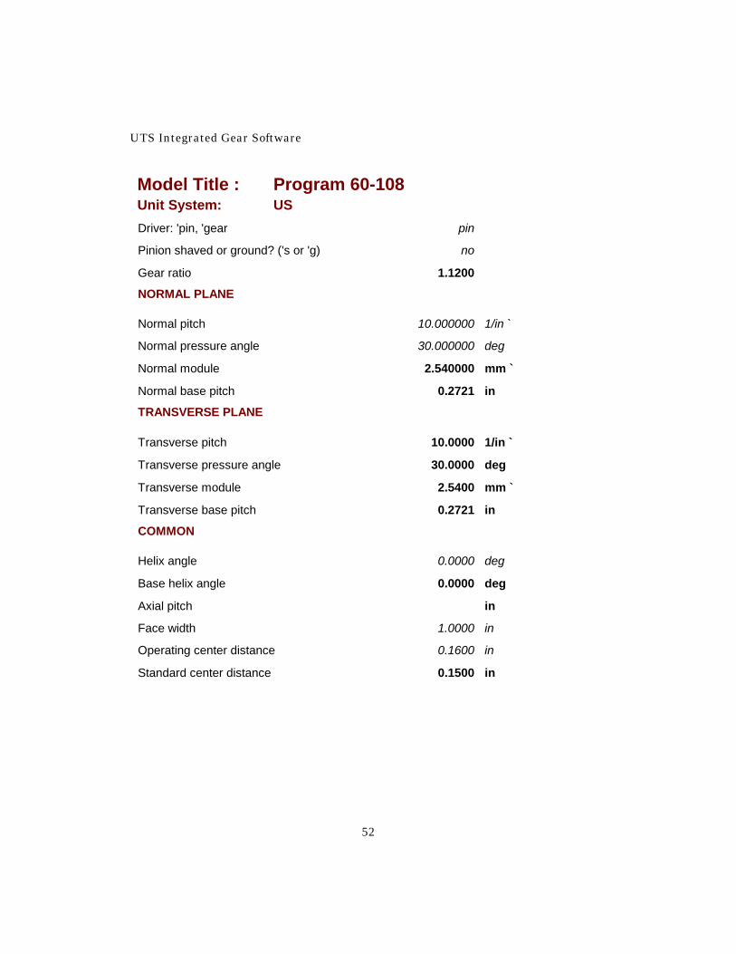
A possible solution to the interference problem is shown on Figure 3-3 and Report 3-2. The pressure angle has been increased to 30 degrees. The outside diameter of the pinion and the inside diameter of the gear have both been set to 2.8 inches and the center distance has been increased by 0.01 inch.

60-108—Internal Gear Contact And Backlash
51
Fig. 3-3
Report 3-2
Model Title : Program 60-108 Unit System: US
CAUTION MESSAGE
CAUTION MESSAGE CONTACT
RATIO
LESS THAN
1.2000
PINION, number of teeth 25
GEAR, number of teeth 28
UTS Integrated Gear Software
52
Model Title : Program 60-108 Unit System: US Driver: 'pin, 'gear pin
Pinion shaved or ground? ('s or 'g) no
Gear ratio 1.1200
NORMAL PLANE
Normal pitch 10.000000 1/in `
Normal pressure angle 30.000000 deg
Normal module 2.540000 mm `
Normal base pitch 0.2721 in
TRANSVERSE PLANE
Transverse pitch 10.0000 1/in `
Transverse pressure angle 30.0000 deg
Transverse module 2.5400 mm `
Transverse base pitch 0.2721 in
COMMON
Helix angle 0.0000 deg
Base helix angle 0.0000 deg
Axial pitch in
Face width 1.0000 in
Operating center distance 0.1600 in
Standard center distance 0.1500 in

60-108—Internal Gear Contact And Backlash
53
Model Title : Program 60-108 Unit System: US
TOOTH THICKNESS & SPACE WIDTH PINION AT REF PD
Normal tooth thickness 0.2233 in
Transverse tooth thickness 0.2233 in
TOOTH THICKNESS & SPACE WIDTH PINION AT OD
Normal tooth thickness 0.0276 in
Transverse tooth thickness 0.0276 in
TOOTH THICKNESS & SPACE WIDTH GEAR AT REF PD
Normal tooth thickness 0.0743 in
Transverse tooth thickness 0.0743 in
Normal space width 0.2399 in
Transverse space width 0.2399 in
TOOTH THICKNESS & SPACE WIDTH GEAR AT ID
Normal tooth thickness 0.0743 in
Transverse tooth thickness 0.0743 in
CLEARANCE (FOR UNDERCUT CHECK)
Root clearance, Pinion (approx) 0.0250 in
DIAMETERS PINION
Outside diameter 2.8000 in
Roll angle at OD 46.9872 deg
Reference pitch diameter 2.5000 in
Pointed tooth diameter 2.8334 in
Base diameter 2.1651 in

UTS Integrated Gear Software
54
Model Title : Program 60-108 Unit System: US DIAMETERS GEAR
Inside diameter 2.8000 in
Roll angle at ID 33.0797 deg
Minimum ID (Involute Interference) 2.4321 in
Reference pitch diameter 2.8000 in
Pointed tooth diameter 2.6595 in
Base diameter 2.4249 in
OPERATING DATA
Working depth 0.1600 in
Basic transverse backlash -0.0011 in
Change in Opr CD from "Std" CD 0.0100 in
Normal backlash 0.0043 in
Transverse backlash 0.0043 in
Transverse pressure angle 35.7181 deg
Helix angle 0.0000 deg
Circular pitch 0.3351 in
Roll angle at pitch point 41.1987 deg
OPERATING DATA PINION
Pitch diameter 2.6667 in
Transverse Tooth Thickness 0.1264 in
Start of active profile 2.4818 in
Roll angle at SAP 32.1055 deg
Normal tooth thickness at SAP 0.2320 in
Transverse tooth thickness at SAP 0.2320 in
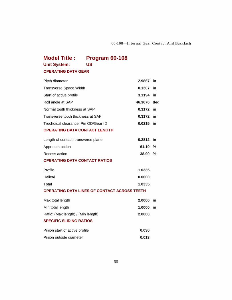
60-108—Internal Gear Contact And Backlash
55
Model Title : Program 60-108 Unit System: US OPERATING DATA GEAR
Pitch diameter 2.9867 in
Transverse Space Width 0.1307 in
Start of active profile 3.1194 in
Roll angle at SAP 46.3670 deg
Normal tooth thickness at SAP 0.3172 in
Transverse tooth thickness at SAP 0.3172 in
Trochoidal clearance: Pin OD/Gear ID 0.0215 in
OPERATING DATA CONTACT LENGTH
Length of contact, transverse plane 0.2812 in
Approach action 61.10 %
Recess action 38.90 %
OPERATING DATA CONTACT RATIOS
Profile 1.0335
Helical 0.0000
Total 1.0335
OPERATING DATA LINES OF CONTACT ACROSS TEETH
Max total length 2.0000 in
Min total length 1.0000 in
Ratio: (Max length) / (Min length) 2.0000
SPECIFIC SLIDING RATIOS
Pinion start of active profile 0.030
Pinion outside diameter 0.013

UTS Integrated Gear Software
56
Model Title : Program 60-108 Unit System: US Gear start of active profile 0.013
Gear inside diameter 0.029
Coefficient of friction 0.6000
Approx power loss 0.44 %
Approx efficiency 99.56 %
AGMA Load sharing ratio, mN 1.0000
AGMA I-factor for durability 1.423 The trochoidal clearance is now 0.0215 inch. The profile contact ratio is quite low at 1.0335, but a slight amount of deflection would bring adjacent teeth into contact because of the very slight clearance of the teeth next to the conjugate tooth on the driving side. The approach action is much larger than the recess action but the specific sliding ratios are very low and not much sliding is taking place. The capacity of this type of drive can be quite high. Figure 3-4A shows the gears in mesh at the first point of contact on the line of action. The close conformity of the teeth can be seen. In Figure 3-4B, 9 teeth are shown. The clearance between the pinion tooth tips and the gear ID is no longer a problem.

60-108—Internal Gear Contact And Backlash
57
Fig. 3-4A

UTS Integrated Gear Software
58
Fig. 3-4B


![Bifurcation and Chaos of Gear Pair System Supported by ... · mesh stiffness, damping, gear errors profile modification and backlash. Cai and Hayashi [9] calculated the opti- mum](https://static.fdocuments.in/doc/165x107/5ec58b34a482d05ea361c337/bifurcation-and-chaos-of-gear-pair-system-supported-by-mesh-stiffness-damping.jpg)