Product Specifications PSS 1-6C1 A E96 Magnetic Flow ... · Product Specifications PSS 1-6C1 A E96...
12
® Product Specifications PSS 1-6C1 A E96 Magnetic Flow Transmitter E96T E96P OR E96S (WITH OPTIONAL OUTPUT METER) E96R (WITH OPTIONAL PRECALIBRATED SPAN ADJUSTMEN) These transmitters convert the low-level, high-impedance ac signal from any Foxboro 1800 or 2800 Series Magnetic Flowtube to a standard transmission signal. EXCELLENT ZERO STABILITY Excellent zero stability is inherent in the design. Unique design of the output stage, and power-driven screens (shields) on the input signal cable ensure superior long-term stability and accurate measurement under all conditions of flow. ADVANCED ELECTRONIC CIRCUITRY Integrated circuit operational amplifiers, hermetically sealed semiconductors, multiple input screening (shielding), and high-quality components throughout provide high sustained accuracy, stability, and outstanding repeatability. PRECALIBRATED SPAN ADJUSTMENT This option allows the user to change the span without shutting down the process, rezeroing the transmitter, or without an external calibrator or other test equipment. VERSATILITY AND COMPATIBILITY Available in 4 mounting configurations: surface, pipe, direct to (integral with) selected 2800 Series Flowtubes, or in a standard 19 in (483 mm) rack (IEC 297). The surface-, pipe-, and rack-mounted versions are completely compatible with any Foxboro 1800 or 2800 Series Flowtube, regardless of style or age. All that is required is a simple calibration adjustment on the transmitter. WIDE VARIETY OF OPTIONS The E96 is offered with a wide variety of options. Precalibrated span adjustment, highly visible 100 mm (4 in) sector scale flow rate indication, rate pulse output, span switching, output damping, and integral totalizer can be ordered with the transmitter.
Transcript of Product Specifications PSS 1-6C1 A E96 Magnetic Flow ... · Product Specifications PSS 1-6C1 A E96...

Product Specifications
PSS 1-6C1 AE96 Magnetic Flow Transmitter
E96T
E96P OR E96S(WITH OPTIONALOUTPUT METER)
E96R (WITH OPTIONAL PRECALIBRATED SPAN ADJUSTMEN)
These transmitters convert the low-level, high-impedance ac signal from any Foxboro 1800 or 2800 Series Magnetic Flowtube to a standard transmission signal.
EXCELLENT ZERO STABILITY
Excellent zero stability is inherent in the design. Unique design of the output stage, and power-driven screens (shields) on the input signal cable ensure superior long-term stability and accurate measurement under all conditions of flow.
ADVANCED ELECTRONIC CIRCUITRY
Integrated circuit operational amplifiers, hermetically sealed semiconductors, multiple input screening (shielding), and high-quality components throughout provide high sustained accuracy, stability, and outstanding repeatability.
PRECALIBRATED SPAN ADJUSTMENT
This option allows the user to change the span without shutting down the process, rezeroing the transmitter, or without an external calibrator or other test equipment.
VERSATILITY AND COMPATIBILITY
Available in 4 mounting configurations: surface, pipe, direct to (integral with) selected 2800 Series Flowtubes, or in a standard 19 in (483 mm) rack (IEC 297). The surface-, pipe-, and rack-mounted versions are completely compatible with any Foxboro 1800 or 2800 Series Flowtube, regardless of style or age. All that is required is a simple calibration adjustment on the transmitter.
WIDE VARIETY OF OPTIONS
The E96 is offered with a wide variety of options. Precalibrated span adjustment, highly visible 100 mm (4 in) sector scale flow rate indication, rate pulse output, span switching, output damping, and integral totalizer can be ordered with the transmitter.
®
PSS 1-6C1 APage 2
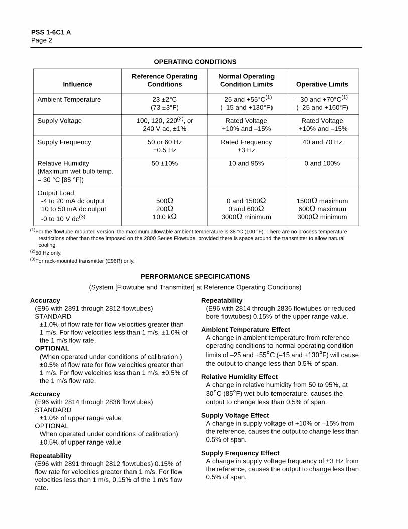
OPERATING CONDITIONS
(1)For the flowtube-mounted version, the maximum allowable ambient temperature is 38 °C (100 °F). There are no process temperature restrictions other than those imposed on the 2800 Series Flowtube, provided there is space around the transmitter to allow natural cooling.
(2)50 Hz only.(3)For rack-mounted transmitter (E96R) only.
PERFORMANCE SPECIFICATIONS
(System [Flowtube and Transmitter] at Reference Operating Conditions)
Accuracy(E96 with 2891 through 2812 flowtubes)STANDARD
±1.0% of flow rate for flow velocities greater than 1 m/s. For flow velocities less than 1 m/s, ±1.0% of the 1 m/s flow rate.
OPTIONAL(When operated under conditions of calibration.) ±0.5% of flow rate for flow velocities greater than 1 m/s. For flow velocities less than 1 m/s, ±0.5% of the 1 m/s flow rate.
Accuracy(E96 with 2814 through 2836 flowtubes)STANDARD
±1.0% of upper range valueOPTIONAL
When operated under conditions of calibration) ±0.5% of upper range value
Repeatability(E96 with 2891 through 2812 flowtubes) 0.15% of flow rate for velocities greater than 1 m/s. For flow velocities less than 1 m/s, 0.15% of the 1 m/s flow rate.
Repeatability(E96 with 2814 through 2836 flowtubes or reduced bore flowtubes) 0.15% of the upper range value.
Ambient Temperature EffectA change in ambient temperature from reference operating conditions to normal operating condition limits of –25 and +55°C (–15 and +130°F) will cause the output to change less than 0.5% of span.
Relative Humidity EffectA change in relative humidity from 50 to 95%, at 30°C (85°F) wet bulb temperature, causes the output to change less than 0.5% of span.
Supply Voltage EffectA change in supply voltage of +10% or –15% from the reference, causes the output to change less than 0.5% of span.
Supply Frequency EffectA change in supply voltage frequency of ±3 Hz from the reference, causes the output to change less than 0.5% of span.
InfluenceReference Operating
ConditionsNormal Operating Condition Limits Operative Limits
Ambient Temperature 23 ±2°C(73 ±3°F)
–25 and +55°C(1)
(–15 and +130°F)–30 and +70°C(1)
(–25 and +160°F)
Supply Voltage 100, 120, 220(2), or240 V ac, ±1%
Rated Voltage+10% and –15%
Rated Voltage +10% and –15%
Supply Frequency 50 or 60 Hz±0.5 Hz
Rated Frequency±3 Hz
40 and 70 Hz
Relative Humidity (Maximum wet bulb temp. = 30 °C [85 °F])
50 ±10% 10 and 95% 0 and 100%
Output Load -4 to 20 mA dc output 10 to 50 mA dc output
-0 to 10 V dc(3)
500Ω200Ω
10.0 kΩ
0 and 1500Ω0 and 600Ω
3000Ω minimum
1500Ω maximum600Ω maximum3000Ω minimum
PSS 1-6C1 APage 3
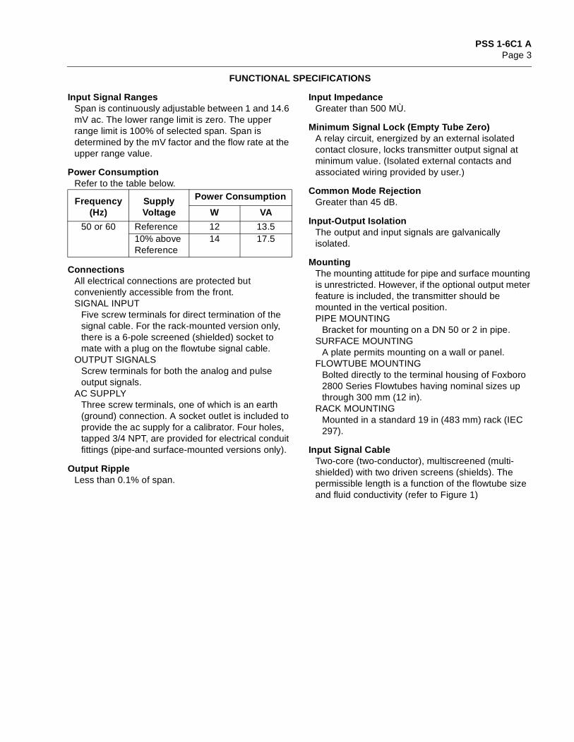
FUNCTIONAL SPECIFICATIONS
Input Signal RangesSpan is continuously adjustable between 1 and 14.6 mV ac. The lower range limit is zero. The upper range limit is 100% of selected span. Span is determined by the mV factor and the flow rate at the upper range value.
Power ConsumptionRefer to the table below.
ConnectionsAll electrical connections are protected but conveniently accessible from the front.SIGNAL INPUT
Five screw terminals for direct termination of the signal cable. For the rack-mounted version only, there is a 6-pole screened (shielded) socket to mate with a plug on the flowtube signal cable.
OUTPUT SIGNALSScrew terminals for both the analog and pulse output signals.
AC SUPPLYThree screw terminals, one of which is an earth (ground) connection. A socket outlet is included to provide the ac supply for a calibrator. Four holes, tapped 3/4 NPT, are provided for electrical conduit fittings (pipe-and surface-mounted versions only).
Output RippleLess than 0.1% of span.
Input ImpedanceGreater than 500 MÙ.
Minimum Signal Lock (Empty Tube Zero)A relay circuit, energized by an external isolated contact closure, locks transmitter output signal at minimum value. (Isolated external contacts and associated wiring provided by user.)
Common Mode RejectionGreater than 45 dB.
Input-Output IsolationThe output and input signals are galvanically isolated.
MountingThe mounting attitude for pipe and surface mounting is unrestricted. However, if the optional output meter feature is included, the transmitter should be mounted in the vertical position.PIPE MOUNTING
Bracket for mounting on a DN 50 or 2 in pipe.SURFACE MOUNTING
A plate permits mounting on a wall or panel.FLOWTUBE MOUNTING
Bolted directly to the terminal housing of Foxboro 2800 Series Flowtubes having nominal sizes up through 300 mm (12 in).
RACK MOUNTINGMounted in a standard 19 in (483 mm) rack (IEC 297).
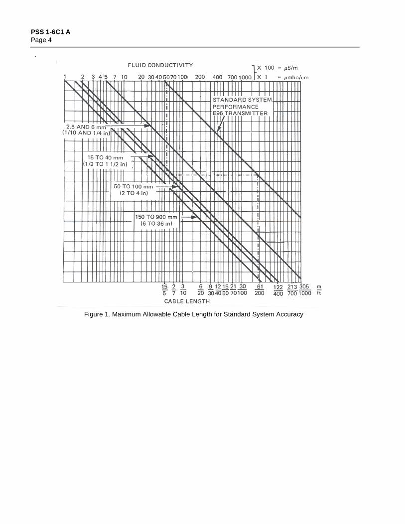
Input Signal CableTwo-core (two-conductor), multiscreened (multi-shielded) with two driven screens (shields). The permissible length is a function of the flowtube size and fluid conductivity (refer to Figure 1)
Frequency (Hz)
Supply Voltage
Power Consumption
W VA
50 or 60 Reference 12 13.510% above Reference
14 17.5
PSS 1-6C1 APage 4
.
Figure 1. Maximum Allowable Cable Length for Standard System Accuracy

PSS 1-6C1 APage 5
PHYSICAL SPECIFICATIONS
Materials of Construction (Enclosures)PIPE, SURFACE, OR FLOWTUBE MOUNTED
The housing and cover are die-cast, low-copper aluminum alloy, finished with a high-build epoxy coating.
RACK MOUNTEDThe housing is steel with an aluminum alloy front panel. The steel housing is finished with light gray paint; and the front panel is finished with dark gray vinyl paint or the equivalent.
Environmental ProtectionThe enclosures for all versions, except the rack mounted, are weatherproof and dusttight as defined by IEC IP66, and provide the watertight protection of NEMA Type 4X. The cover seats on a cork/Neoprene composition gasket.
Approximate MassPIPE, SURFACE, AND FLOWTUBE MOUNTED
9 kg (20 lb)RACK MOUNTED
5.5 kg (12 lb)
PRODUCT SAFETY SPECIFICATIONS
Electrical Classification
Notes
1. E96P or E96S: All options and option combinations AF, BE, BF, BG, BI, BFI, CE, CF, CG, CH, FH, FI, FK, FL, and any of these combinations with option J.
For E96T: Options A, E, F, G, H, I, and J and option combnations AF, FH, FI, and any of these combinations with option J.
2. Options A, E, F, G, H, I, and J and option combinations AF, FH, FI, and any of these combinations with option J.
Testing Laboratory, Types of Protection, and Area Classification Conditions of Certification
Electrical Classification Code
CSA certified for use in Ordinary Locations. E96R only. CS–E/CG–A
CSA certified for use in Ordinary Locations and Class I, Division 2, Groups A, B, C, and D hazardous locations.
Mounting Codes P, S, and T only. Temperature Class T3C.
CS–E/CN–A
CSA certified suitable for Type Y Purging for Class I, Division 1, Groups A, B, C, and D.
Mounting Codes P, S, and T only. Option Codes B, C, D, K, and L and AS Code PNU are not approved. Temperature Class T3C.
CS–E/CP–A
FM certified for use in Ordinary Locations. ——— CS–E/FG–A
FM certified for use in Class I, Division 2, Groups A, B, C, and D hazardous locations. Intrinsically safe connection to flowtube electrodes, Class I, Division 1, Groups A, B, C, and D.
Mounting Codes P, S, and T only. For approved options, see Note 1. Temperature Class T3C.
CS–E/FNB–A
FM certified suitable for Type Y Purging for Class I, Division 1, Groups A, B, C, and D. Intrinsically safe connection to flowtube electrodes, Class I, Division 1, Groups A, B, C, and D.
Mounting Codes P, S, and T only. For approved options, see Note 2. Temperature Class T3C.
CS–E/FPB–A
PSS 1-6C1 APage 6
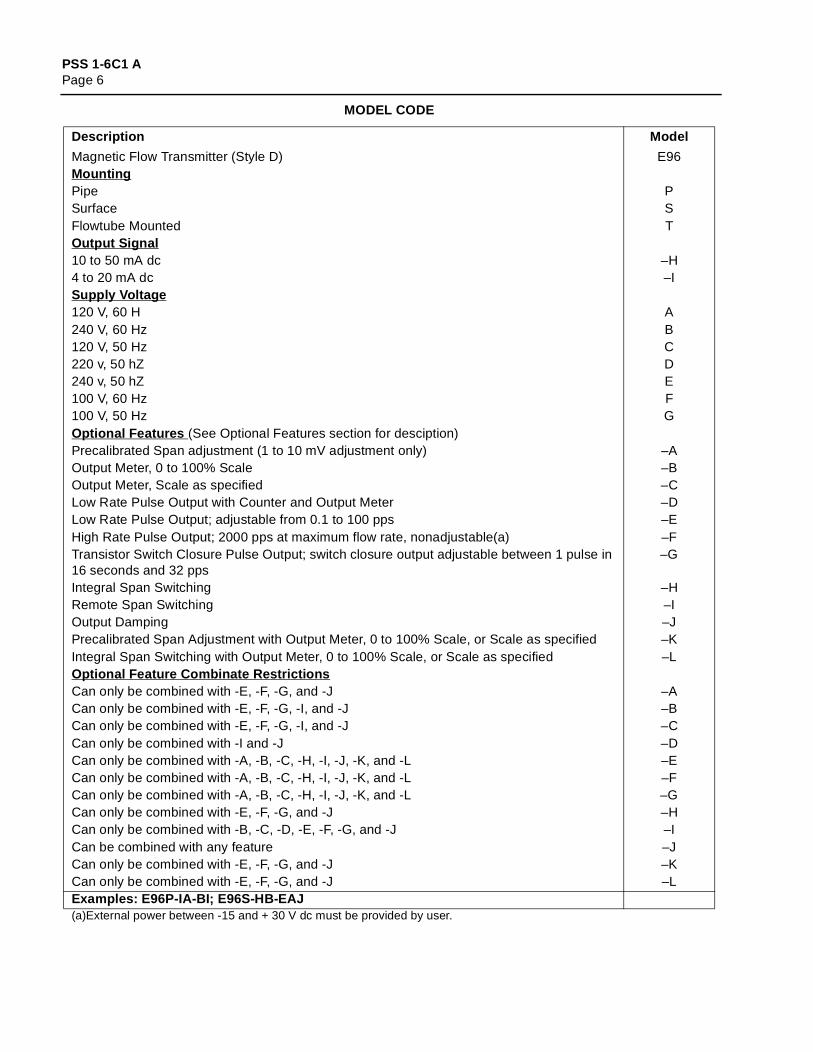
MODEL CODE
Description Model
Magnetic Flow Transmitter (Style D) E96MountingPipe PSurface SFlowtube Mounted TOutput Signal10 to 50 mA dc –H4 to 20 mA dc –ISupply Voltage120 V, 60 H A240 V, 60 Hz B120 V, 50 Hz C220 v, 50 hZ D240 v, 50 hZ E100 V, 60 Hz F100 V, 50 Hz GOptional Features (See Optional Features section for desciption)Precalibrated Span adjustment (1 to 10 mV adjustment only) –AOutput Meter, 0 to 100% Scale –BOutput Meter, Scale as specified –CLow Rate Pulse Output with Counter and Output Meter –DLow Rate Pulse Output; adjustable from 0.1 to 100 pps –EHigh Rate Pulse Output; 2000 pps at maximum flow rate, nonadjustable(a) –FTransistor Switch Closure Pulse Output; switch closure output adjustable between 1 pulse in 16 seconds and 32 pps
–G
Integral Span Switching –HRemote Span Switching –IOutput Damping –JPrecalibrated Span Adjustment with Output Meter, 0 to 100% Scale, or Scale as specified –KIntegral Span Switching with Output Meter, 0 to 100% Scale, or Scale as specified –LOptional Feature Combinate RestrictionsCan only be combined with -E, -F, -G, and -J –ACan only be combined with -E, -F, -G, -I, and -J –BCan only be combined with -E, -F, -G, -I, and -J –CCan only be combined with -I and -J –DCan only be combined with -A, -B, -C, -H, -I, -J, -K, and -L –ECan only be combined with -A, -B, -C, -H, -I, -J, -K, and -L –FCan only be combined with -A, -B, -C, -H, -I, -J, -K, and -L –GCan only be combined with -E, -F, -G, and -J –HCan only be combined with -B, -C, -D, -E, -F, -G, and -J –ICan be combined with any feature –JCan only be combined with -E, -F, -G, and -J –KCan only be combined with -E, -F, -G, and -J –LExamples: E96P-IA-BI; E96S-HB-EAJ(a)External power between -15 and + 30 V dc must be provided by user.
PSS 1-6C1 APage 7
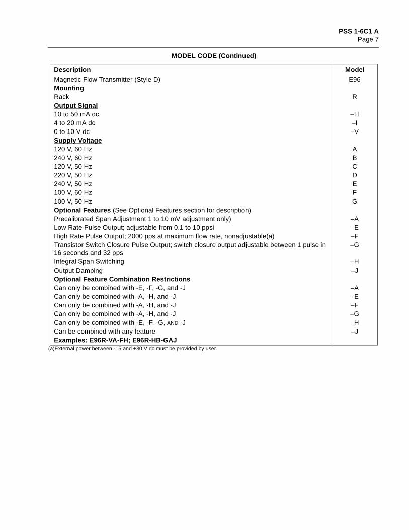
(a)External power between -15 and +30 V dc must be provided by user.
Magnetic Flow Transmitter (Style D) E96MountingRack ROutput Signal10 to 50 mA dc –H4 to 20 mA dc –I0 to 10 V dc –VSupply Voltage120 V, 60 Hz A240 V, 60 Hz B120 V, 50 Hz C220 V, 50 Hz D240 V, 50 Hz E100 V, 60 Hz F100 V, 50 Hz GOptional Features (See Optional Features section for description)Precalibrated Span Adjustment 1 to 10 mV adjustment only) –ALow Rate Pulse Output; adjustable from 0.1 to 10 ppsi –EHigh Rate Pulse Output; 2000 pps at maximum flow rate, nonadjustable(a) –FTransistor Switch Closure Pulse Output; switch closure output adjustable between 1 pulse in 16 seconds and 32 pps
–G
Integral Span Switching –HOutput Damping –JOptional Feature Combination RestrictionsCan only be combined with -E, -F, -G, and -J –ACan only be combined with -A, -H, and -J –ECan only be combined with -A, -H, and -J –FCan only be combined with -A, -H, and -J –GCan only be combined with -E, -F, -G, AND -J –HCan be combined with any feature –JExamples: E96R-VA-FH; E96R-HB-GAJ
MODEL CODE (Continued)
Description Model
PSS 1-6C1 APage 8
OPTIONAL FEATURES
Precalibrated Span AdjustmentThis is a 10-turn potentiometer that provides continuous span adjustment within the range of 1 to 10 mV without a signal calibrator.
Output MeterA moving coil meter, with a nominal 100 mm (4 in) scale, provides continuous local indication of the transmitter output. The scale is graduated 0 to 100%, or as specified. The accuracy of the meter is ±2% of span.
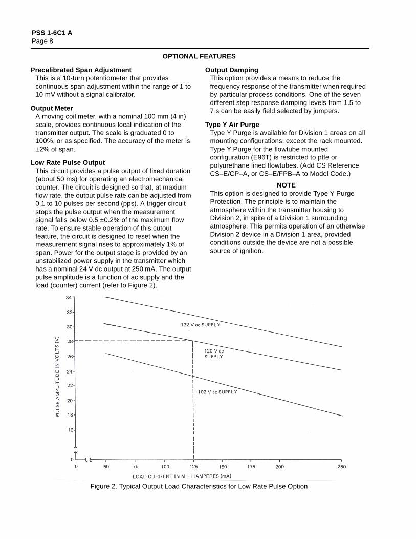
Low Rate Pulse OutputThis circuit provides a pulse output of fixed duration (about 50 ms) for operating an electromechanical counter. The circuit is designed so that, at maxium flow rate, the output pulse rate can be adjusted from 0.1 to 10 pulses per second (pps). A trigger circuit stops the pulse output when the measurement signal falls below 0.5 ±0.2% of the maximum flow rate. To ensure stable operation of this cutout feature, the circuit is designed to reset when the measurement signal rises to approximately 1% of span. Power for the output stage is provided by an unstabilized power supply in the transmitter which has a nominal 24 V dc output at 250 mA. The output pulse amplitude is a function of ac supply and the load (counter) current (refer to Figure 2).
Output DampingThis option provides a means to reduce the frequency response of the transmitter when required by particular process conditions. One of the seven different step response damping levels from 1.5 to 7 s can be easily field selected by jumpers.
Type Y Air PurgeType Y Purge is available for Division 1 areas on all mounting configurations, except the rack mounted. Type Y Purge for the flowtube mounted configuration (E96T) is restricted to ptfe or polyurethane lined flowtubes. (Add CS Reference CS–E/CP–A, or CS–E/FPB–A to Model Code.)
NOTEThis option is designed to provide Type Y Purge Protection. The principle is to maintain the atmosphere within the transmitter housing to Division 2, in spite of a Division 1 surrounding atmosphere. This permits operation of an otherwise Division 2 device in a Division 1 area, provided conditions outside the device are not a possible source of ignition.
Figure 2. Typical Output Load Characteristics for Low Rate Pulse Option

PSS 1-6C1 APage 9
OPTIONAL FEATURES (Cont.)
Transistor Switch Closure Pulse OutputThis option is designed for use with electronic totalizers or systems requiring transistor switch closure input. The output is a transistor switch isolated by a photocoupler. For a measurement signal equivalent to 100% of flow rate, the output is adjustable between 1 pulse in 16 s and 32 pps. The output duty cycle is 50%. A trigger circuit is arranged so that when the measurement signal falls below 0.75 ±0.2% of the maximum flow rate, operation of the pulse generating circuit is interrupted. Power for the output switch is supplied by the receiving totalizer or system. The switch rating is 30 V dc, 30 mA maximum. The maximum load capacity is 0.1 µF. The maximum length of the output signal cable is 90 m (300 ft).
Span SwitchingThis option provides a means for switching the span of the transmitter to any one of four precalibrated spans between 1 and 14 mV. Either integral or remote switching is available. A remote switch can be mounted up to 30 m (100 ft) from the transmitter.
Cable Adapter AssemblyUsed with E96P and E96S. Provides a convenient means of terminating the input signal cable to the transmitter. (Specify Foxboro part number P0122JX.)
Low Rate Pulse Output with Counter and Output Meter
This is the Low Rate Pulse option with a built-in output meter and a non-resettable 7 digit electromechanical totalizer. Both the output meter and the totalizer are visible through the housing window. This option is shown in Figure 3.
High Rate Pulse OutputThis circuit provides a high rate pulse output signal. The pulse rate is not field adjustable. The pulse is of fixed duration (about 85 µs) and has an amplitude of 10 ±1 V peak-to-peak. A trigger circuit stops the pulse output when the measurement signal falls below 0.5 ±0.2% of the maximum flow rate. Like the Low Rate Pulse Output option, this circuit is also designed to reset when the measurement signal rises to approximately 1% of span. Some of the functional specifications of this option are:LOAD RESISTANCE
500Ω (minimum)LOAD CAPACITANCE
0.22 µF (maximum)POWER
An external power supply is required. The voltage must be between +15 and +30 V dc. The minimum current must be 30 mA. Reverse polarity protection is provided.
RISE TIME2.5 µs maximum at zero µF load capacity; 15.0 µs maximum at 0.22 µF load capacity.
FALL TIMELess than 15 µs
ISOLATIONThe output is galvanically isolated from both input and earth (ground).
TropicalizationPrinted wiring board assemblies are conformally coated to protect against environments such as dirt, dust, and moisture. (Add AS Reference CBC to Model Code.)
Figure 3. Low Rate Output with Counter and Meter (–D) Option

PSS 1-6C1 APage 10
ORDERING INSTRUCTIONS
1. Model Number2. Input Range3. Electrical Classification and Certification Code4. Signal Cable Length (Must be within the flowtube line size and fluid conductivity limits in Figure 1.)5. Optional Features (CS Reference or AS Reference)6. With Span-switching Option (-H, -I, or -L) specify the following:
Range 1Range 2Range 3Range 4
7. Tag or Application

PSS 1-6C1 APage 11
DIMENSIONS—NOMINAL
PSS 1-6C1 APage 12
The Foxboro Company33 Commercial StreetFoxboro, MA 02035-2099United States of Americahttp://www.foxboro.comInside U.S.: 1-888-FOXBORO
(1-888-369-2676)Outside U.S.: Contact your local Foxboro representative.Facsimile (508) 549-4492
An Invensys company
Foxboro is a registered trademark of The Foxboro Company.Invensys is a trademark of Invensys plc.Neoprene is a trademark of E.I. duPont de Nemours and Company.All other brand names may be trademarks of their respective companies.
Copyright 1986-1994 The Foxboro CompanyAll rights reserved
MB 010 Printed in U.S.A. 0494