Product Manual KNX IP Router IPR/S 2 - ABB Group · PDF fileProduct Manual ABB i-bus® KNX...
44
Product Manual ABB i-bus ® KNX IP Router IPR/S 2.1 Intelligent Installation Systems ABB
Transcript of Product Manual KNX IP Router IPR/S 2 - ABB Group · PDF fileProduct Manual ABB i-bus® KNX...

Product Manual ABB i-bus® KNX IP Router IPR/S 2.1 Intelligent Installation Systems
ABB

This manual describes the function of the IP Router IPR/S 2.1 with the application program IP Routing. Subject to changes and errors excepted. Exclusion of liability: Despite checking that the contents of this document match the hardware and software, deviations cannot be completely excluded. We therefore cannot accept any liability for this. Any necessary corrections will be inserted in new versions of the manual. Please inform us of any suggested improvements.

ABB i-bus KNX Contents
© 2008 ABB STOTZ-KONTAKT GmbH i
Contents Page
1 General 3
1.1 Product and functional overview...........................................................3
2 Device technology 5
2.1 Technical data.......................................................................................5 2.2 Circuit diagram......................................................................................7 2.3 Dimension drawing ...............................................................................8 2.4 Assembly and installation .....................................................................9 2.5 Description of the inputs and outputs .................................................10 2.6 Operating controls ..............................................................................10 2.7 Display elements ................................................................................11
3 Commissioning 13
3.1 Overview.............................................................................................13 3.2 Parameters .........................................................................................13 3.2.1 Parameter window KNX -> LAN.......................................................14 3.2.2 Parameter window LAN -> KNX.......................................................16 3.2.3 Parameter window IP settings..........................................................18 3.2.4 Parameter window IP address .........................................................20 3.2.5 Parameter window IP communication Multicast ..............................22 3.2.6 Parameter window IP communication Unicast.................................24 3.3 Communication objects ......................................................................26 3.4 IPR/S as a programming interface .....................................................26 3.4.1 Settings from ETS3.0f ......................................................................27 3.4.2 Settings for ETS3.0e ........................................................................29
4 Planning and application 31
4.1 The IP Router in the network ..............................................................31 4.1.1 IP Address of the IPR/S ...................................................................31 4.1.2 KNX telegrams in the network..........................................................32 4.1.3 IPR/S as an area coupler .................................................................33 4.1.4 IPR/S as a line coupler.....................................................................34 4.1.5 Mixed topology .................................................................................35 A.1 Ordering information ...........................................................................37 A.2 Notes...................................................................................................38 A.3 Notes...................................................................................................39 A.4 Notes...................................................................................................40


ABB i-bus KNX General
© 2008 ABB STOTZ-KONTAKT GmbH 3
1 General
The IP Router IPR/S 2.1 connects the KNX bus with the Ethernet network. KNX telegrams can be sent to or received from other devices via the network. The device uses the KNXnet/IP protocol from the KNX Association for communication. This is not compatible with the EIBlib/IP protocol as used for example, by the IP Gateway IG/S 1.1.
In older documents and in the ETS 3.0e the KNXnet/IP protocol is also referred to as the EIBnet/IP protocol.
Both protocols and specifications are identical.
1.1 Product and functional overview
The IP Router in addition to the tunnelling function for point-to-point communication, also incorporates the functions of a line coupler (routing). The IP Router can thus distribute telegrams in the network to other lines or areas, as well as receive telegrams from there.
1.1.0 2.1.0 15.1.0


ABB i-bus KNX Device technology
© 2008 ABB STOTZ-KONTAKT GmbH 5
2 Device technology
IPR/S 2.1
The IP Router 2.1 is a modular installation device (MDRC) and forms the interface between KNX installations and IP networks. It can be used as a fast line and area coupler and can utilise the local network (LAN) for fast exchange of telegrams between the lines/areas. KNX devices can be programmed via the LAN using ETS 3.0. The device uses the KNXnet/IP protocol from the KNX Association (Routing and Tunnelling). The IP address can be fixed or can be received from a DHCP server. The power supply range is from 10 to 30 V DC.
2.1 Technical data
Supply Supply voltage Us 10…30 V DC via plug-in terminal
Ripple: < 5 %
Power consumption Maximum 1.9 W at 10 V
Current consumption Maximum 190 mA at 10 V
Leakage loss Maximum 1.9 W at 10 V
Rated voltage Un 12 V DC
Rated current In 145 mA at 12 V
Current consumption KNX From KNX < 10 mA
Connections KNX Bus connection terminal
Plug-in terminal for operating voltage Plug-in terminal
LAN RJ45 socket for 10/100BaseT, IEEE 802.3
networks, AutoSensing
Operating and display elements LED red and button For assignment of the physical address
LED green Operating mode display
LED yellow Network connection indicator
KNX telegram traffic indicator
Enclosure IP 20 to DIN EN 60529
Safety class II to DIN EN 61140
Isolation category Overvoltage category
Pollution degree
III to DIN EN 60664-1
2 to DIN EN 60664-1
KNX safety extra low voltage SELV 24 V DC
Temperature range Operation 0 °C…+45 °C
Storage -25 °C…+55 °C
Transport -25 °C…+70 °C
Ambient conditions Maximum air humidity 93 %, no condensation allowed
2CD
C 0
71 1
12 F
0008

ABB i-bus KNX Device technology
© 2008 ABB STOTZ-KONTAKT GmbH 6
Design Modular installation device (MDRC) Modular installation device, ProM
Dimensions 90 x 36 x 64 mm (H x W x D)
Mounting width 2 modules at 18 mm
Mounting depth 68 mm
Installation On 35 mm mounting rail to DIN EN 60 715
Mounting position as required
Weight 0.100 kg
Housing, colour Plastic housing, grey
Approvals KNX to EN 50 090-1, -2
CE mark in accordance with the EMC guideline and
low voltage guideline
Application program Maximum number of
communication objects
Maximum number of group
addresses
Maximum number of
associations
Routing 0 0 0
Note
The programming requires EIB Software Tool ETS3 V3.0e or higher.
If ETS3 is used a *.VD3 or higher type file must be imported. The application program is available in the ETS3 at ABB/System devices/Routing.
The device does not support the closing function of a project or the KNX device in the ETS. If you inhibit access to all devices of the project with a BCU code (ETS3), it has no effect on this device. Data can still be read and programmed.

ABB i-bus KNX Device technology
© 2008 ABB STOTZ-KONTAKT GmbH 7
2.2 Circuit diagram
IPR/S 2.1
1 LED ON 6 Programming LED
2 LED LAN/LINK 7 Programming button
3 LED telegram 8 Label carrier
4 Supply voltage connection 9 LAN connection
5 KNX connection
2CD
C 0
72 1
86 F
0007

ABB i-bus KNX Device technology
© 2008 ABB STOTZ-KONTAKT GmbH 8
2.3 Dimension drawing
2CD
C 0
71 1
12 F
0008

ABB i-bus KNX Device technology
© 2008 ABB STOTZ-KONTAKT GmbH 9
2.4 Assembly and installation
Accessibility to the device for the purpose of operation, testing, visual inspection, maintenance and repair must be provided compliant to DIN VDE 0100-520.
Commissioning requirements
In order to commission the device, a PC with ETS from ETS3 V3.0e or higher as well as an interface to the ABB i-bus®, e.g. via a KNX interface as well as a supply voltage in the range from 10 to 30 V DC is required.
If the IP Router or other KNX devices are to be programmed via a network (LAN), a PC with LAN connection is required.
The installation and commissioning may only be carried out by electrical specialists. The appropriate norms, guidelines, regulations and specifications should be observed when planning and setting up electrical installations.
Protect the device from damp, dirt and damage during transport, storage and operation.
Only operate the device within the specified technical data limits!
The device should only be operated in an enclosed housing (distribution board)!
Supplied state
The device is assigned with the physical address 15.15.0 in the factory and a second physical address 15.15.100 for a tunnelling connection.
The application program is preloaded in the factory. The IP address is set to automatic IP assignment (DHCP/AutoIP).
Assignment of the physical address
The assignment of the address of the ABB i-bus® IP ROUTER is carried out via the ETS and the programming button on the device.
The device features a programming button for assignment of the physical device address. The red programming LED lights up after the button has been pushed. It switches off as soon as the ETS has assigned the physical address or the programming button is pressed again.
Cleaning
If devices become dirty, they can be cleaned using a dry cloth. Should a dry cloth not remove the dirt, the devices can be cleaned using a slightly damp cloth and soap solution. Corrosive agents or solutions should never be used.
Maintenance
The device is maintenance-free. No repairs should be carried out by unauthorised personnel if damage occurs, e.g. during transport and/or storage. The warranty expires if the device is opened.

ABB i-bus KNX Device technology
© 2008 ABB STOTZ-KONTAKT GmbH 10
2.5 Description of the inputs and outputs
Supply voltage input 10 to 30 V DC
Only a DC voltage in a range of 10 to 30 V may be connected to the power supply input. We recommend using an NT/S power supply from our range. Once the supply voltage has been connected to the system, a start routine is executed in the device. As soon as it is ready for operation – a maximum of 40 seconds after connecting the supply voltage – the ON LED on front of the device lights up.
Caution The supply voltage must be between 10 to 30 V DC.
Otherwise the device may be damaged!
KNX connection
The supplied bus connection terminal is used to connect to the KNX bus.
Note
Programming requires ETS3 from version 3.0e or higher.
LAN connection
The network connection is carried out via an Ethernet RJ 45 interface for LAN networks. The network interface can be operated with a transmission speed of 10/100 Mbit/s. Network activity is indicated by the LAN/LINK LED on the front of the device.
2.6 Operating controls
There are no operating controls located on the IP Router.

ABB i-bus KNX Device technology
© 2008 ABB STOTZ-KONTAKT GmbH 11
2.7 Display elements
Three indicator LEDs are located on the front of the IPR/S:
ON LAN/LINK Telegram
ON
The LED lights up if the power supply is available and the device is ready for operation.
The LED flashes when the device starts-up, a maximum 40 seconds after the supply voltage is applied.
LAN/LINK
The LED lights up if the device detects a connection to the network.
The LED flashes if the device detects activity on the network, e.g. when data is exchanged.
Telegram
The LED lights up when a connection to the KNX is available.
The LED flashes if the device detects a telegram on the KNX.


ABB i-bus KNX Commissioning
© 2008 ABB STOTZ-KONTAKT GmbH 13
3 Commissioning
3.1 Overview
Parameterisation of the IP Router is implemented using the Engineering Tool Software ETS3 from version 3.0e.
3.2 Parameters
This chapter describes the parameters of the IP Router using the parameter window. The parameter window features a dynamic structure so that further parameters or whole parameter windows may be enabled depending on the parameterisation and the function of the outputs.
The default values of the parameters are underlined, e.g.
Option: yes no

ABB i-bus KNX Commissioning
© 2008 ABB STOTZ-KONTAKT GmbH 14
3.2.1 Parameter window KNX -> LAN
In the parameter window KNX -> LAN it is possible to define the processing of telegrams from the KNX system to the LAN network.
Group telegrams main groups 0 to 13
Options: filter route block
This parameter defines if the telegrams with group addresses of the main groups 0 to 13 are filtered, routed or blocked.
filter: The telegrams with the group addresses of the main groups 0 to 13 from the KNX to the LAN are filtered in accordance with the filter table, which is automatically calculated by the ETS.
route: All group telegrams of main groups 0 to 13 are routed without considering the filter table settings. This setting is only useful for commissioning and diagnostics. It should not be used during normal operation.
block: All group telegrams from the KNX to the LAN are blocked without considering the filter table settings.

ABB i-bus KNX Commissioning
© 2008 ABB STOTZ-KONTAKT GmbH 15
Group telegrams main groups 14 and 15
Options: route block
This parameter defines if the telegrams with group addresses of the main groups 14 and 15 are routed or blocked. As ETS cannot compute filter tables for the main groups 14 and 15, these group addresses can only be routed or blocked.
route: All group telegrams of main groups 14 and 15 are routed.
block: No group telegrams of main groups 14 and 15 are transferred from the KNX to the LAN.
Physically addressed telegrams and broadcast telegram
Options: filter block
This parameter defines whether the physically addressed telegrams or broadcast telegrams, e.g. group addresses 0/0/0 are filtered or blocked.
filter: Only the telegrams from the KNX to the LAN which are supposed to exit the line are sent.
block: Physically addressed telegrams and broadcast telegrams are not processed by the IPR/S. With this setting it is not possible to send physically addressed telegrams from a line of a lower level than the IPR/S, to another line, e.g. during programming.
Telegram acknowledge for group telegrams
Options: only if routed always
This parameter determines if group telegrams are to be acknowledged by a telegram.
only if routed: The group telegrams are only acknowledged (send ACK) if they are also routed by an IP Router to the LAN. Thus, only telegrams which are also entered in the IPR/S filter table are acknowledged.
always: All group telegrams on the KNX are acknowledged by the IPR/S.

ABB i-bus KNX Commissioning
© 2008 ABB STOTZ-KONTAKT GmbH 16
3.2.2 Parameter window LAN -> KNX
In the parameter window LAN -> KNX it is possible to define the processing of telegrams from the LAN network to the KNX system.
Group telegrams main groups 0 to 13
Options: filter route block
This parameter defines if the telegrams with group addresses of the main groups 0 to 13 are filtered, routed or blocked.
filter: The telegrams with the group addresses of the main groups 0 to 13 from the LAN to the KNX are filtered in accordance with the filter table, which is automatically calculated by the ETS.
route: All group telegrams of main groups 0 to 13 are routed without considering the filter table settings. This setting is only useful for commissioning and diagnostics. It should not be used during normal operation.
block: All group telegrams from the LAN to the KNX are blocked without considering the filter table settings.

ABB i-bus KNX Commissioning
© 2008 ABB STOTZ-KONTAKT GmbH 17
Group telegrams main groups 14 and 15
Options: route block
This parameter defines if the telegrams with group addresses of the main groups 14 and 15 are routed or blocked. As ETS cannot compute filter tables for the main groups 14 and 15, these group addresses can only be routed or blocked.
route: All group telegrams of main groups 14 and 15 are routed.
block: No group telegrams of main groups 14 and 15 are transferred from the LAN to the KNX.
Physically addressed telegrams and broadcast telegram
Options: filter block
This parameter defines whether the physically addressed telegrams or broadcast telegrams, e.g. group addresses 0/0/0 are filtered or blocked.
filter: Only the telegrams from the LAN to the KNX which are supposed to enter the line are sent.
block: Physically addressed telegrams and broadcast telegrams are not processed by the IPR/S. With this setting, physically addressed telegrams or broadcast telegrams from the LAN to the KNX are blocked

ABB i-bus KNX Commissioning
© 2008 ABB STOTZ-KONTAKT GmbH 18
3.2.3 Parameter window IP settings
In the parameter window IP settings, settings on the IP side of the IP Router are undertaken.
Device name [max. 30 char.]
Options: ABB IP-Router IPR/S
The device name is used for identification of the device on the LAN. After a search query, e.g. by the ETS, every KNXnet/IP device reports its name and can be allocated accordingly. For example, the installation location can be identified by the names assigned to the devices, e.g. IPR/S, HALL, SUB7, etc.
The text may be a maximum of 30 characters in length. This name is also displayed when this device is determined in the ETS as the communications interface.
For further information see: IPR/S as a programming interface
IP address assignment
Options: automatically fixed
automatically: In the standard setting the IP Router expects the assignment of an IP address by a DHCP server (dynamic host configuration protocol). This server responds to a request by assigning a free IP address to the device. If a DHCP server is not available in the network or it does not respond within 30 seconds, the device starts an auto IP procedure. It assigns itself with an address from the reserved range for auto IP addresses (169.254.xxx.yyy).
fixed: If no DHCP server is installed on the network or if the IP address should remain static, it can be assigned as fixed. The parameter window IP Address appears.

ABB i-bus KNX Commissioning
© 2008 ABB STOTZ-KONTAKT GmbH 19
Use special setup for IP
Options: no yes
no: The IPR/S sends the telegrams as multicasts on the IP network with the standard address 224.0.23.12.
yes: The standard setting is not used. The parameter window IP communication appears.

ABB i-bus KNX Commissioning
© 2008 ABB STOTZ-KONTAKT GmbH 20
3.2.4 Parameter window IP address
The parameter window IP address is only visible if on the parameter page IP settings the option fixed has been selected for the IP address assignment parameter.
IP address
Options: Byte x 0…255
The IP address is the unique address of the IP Router in the LAN. This address should be entered in a byte-by-byte manner, e.g. as follows for address 192.168.0.10:
Byte 1: 192
Byte 2: 168
Byte 3: 0
Byte 4: 10
Subnet mask
Options: Byte x 0…255
The Subnet mask defines the network class. The subnet mask must be set to reflect the number and structure of the subnet. In the simplest case of a small network the subnet mask 255.255.255.0 should be set as follows:
Byte 1: 255
Byte 2: 255
Byte 3: 255
Byte 4: 0

ABB i-bus KNX Commissioning
© 2008 ABB STOTZ-KONTAKT GmbH 21
Default gateway
Options: Byte x 0…255
The parameter Default gateway defines the connection point, e.g. the IP address of a Router between networks through which IP telegrams are transferred. These gateways are only available in larger networks. For smaller networks the setting 0.0.0.0 can be retained.

ABB i-bus KNX Commissioning
© 2008 ABB STOTZ-KONTAKT GmbH 22
3.2.5 Parameter window IP communication Multicast
The parameter window IP communication is only visible if on the parameter page IP settings the option yes has been selected for the Use special setup for IP parameter.
Type of IP communication
Options: Multicast Unicast
The type of IP communication defines the type of telegrams that the IP Router sends on the IP network.
Multicast: This is the defined type of communication for KNX-IP devices for KNXnet/IP from the KNX association. This setting should be retained and only changed if the existing network demands that telegrams are sent as Unicast.
Unicast: The routing for the device is switched off. The IP telegram is only sent as a Unicast to the set addresses. This special communication is not compliant to the KNXnet/IP specification and currently only functions (date 08/2008) between ABB-IPR/S devices.

ABB i-bus KNX Commissioning
© 2008 ABB STOTZ-KONTAKT GmbH 23
IP routing multicast address
Options: Byte x 0…255
The IP routing multicast address defines the target address of the IP telegrams of the IPR/S. The preset address 224.0.23.12 is the defined address for the KNXnet/IP from the KNX Association in conjunction with IANA for KNX-IP devices. This address should be retained and only changed if the existing network demands that another address be used.
Important
All IP Routers or other KNXnet/IP devices which are required to exchange telegrams on the IP network must use the same routing multicast IP address.
If devices are to be used in the same network but do not need to exchange telegrams, they must use different routing multicast IP addresses.

ABB i-bus KNX Commissioning
© 2008 ABB STOTZ-KONTAKT GmbH 24
3.2.6 Parameter window IP communication Unicast
The parameter window IP communication is only visible if on the parameter page IP settings the option yes has been selected for the Use special setup for IP parameter.
Type of IP communication
Options: Multicast Unicast
The type of IP communication defines the type of telegrams that the IPR/S sends on the IP network.
Multicast: This is the defined type of communication for KNX-IP devices for KNXnet/IP from the KNX association. This setting should be retained and only changed if the existing network demands that telegrams are sent as Unicast.
Unicast: The routing for the device is switched off. The IP telegram is only sent as a Unicast to the set addresses. This special communication is not compliant to the KNXnet/IP specification and currently only functions (date 08/2008) between ABB-IPR/S devices.
IP routing unicast address 1/2
Options: Byte x 0…255
The Unicast IP address 1 defines the target address of the IP telegram of the IP Router.

ABB i-bus KNX Commissioning
© 2008 ABB STOTZ-KONTAKT GmbH 25
Unicast IP port 1/2
Options: 3671
This parameter defines the port for the IP address 1 or 2. No generally reserved ports may be used, e.g. for http, ftp or 0-1024, 1900, 1901, 50000, 50001, 50002, 51000-51255. If one of these ports is entered Unicast transmission is not activated.

ABB i-bus KNX Commissioning
© 2008 ABB STOTZ-KONTAKT GmbH 26
3.3 Communication objects
The IP Router IPR/S has no KNX communication objects.
3.4 IPR/S as a programming interface
The IP Router IPR/S can be used together with the ETS as a programming interface. The device provides an additional physical address for this purpose which can be used for a tunnelling connection, e.g. for ETS:
Note
The physical address for the tunnelling connection must fit the topology. For this reason 1.1.255 has been used in the above example.
1.1.10
1.1.11
1.1.0
1.1.255
Visualisation PC with ETS

ABB i-bus KNX Commissioning
© 2008 ABB STOTZ-KONTAKT GmbH 27
3.4.1 Settings from ETS3.0f
The ETS connects for programming purposes to this second physical address in order to program devices in the line.
For this purpose the ETS must be set as follows via the window Extras/Options/Communication:
Click Configure interface, a new window appears.
Click on New.
The name should be overwritten with a name which matches the KNX installation, e.g. IPR Room 112.
Select the KNXnet/IP type.
The ETS now searches automatically via the LAN connection for KNXnet/IP devices in the network and indicates them in the combination field under KNXnet/IP device.
Select the device from the combination field. If it is not shown click on Rescan.
After selection of the device, its data, e.g. MAC or plain text name, are displayed:
With the acknowledgement OK, the setup of the IPR/S as a programming interface is completed.
If the required device is not connected, the connection can be checked by clicking on the button KNXnet/IP Diagnostic Assistant.

ABB i-bus KNX Commissioning
© 2008 ABB STOTZ-KONTAKT GmbH 28
After completion of the settings, the connection to the IPR/S can be tested by clicking on Test in the new window:
The physical address of the tunnelling connection can be set as a programming interface via the Settings button. The following window appears:
It must be assured that the physical address of the tunnelling connection matches the topology, e.g. 1.1.255.

ABB i-bus KNX Commissioning
© 2008 ABB STOTZ-KONTAKT GmbH 29
3.4.2 Settings for ETS3.0e
The settings for the ETS3.0e are mainly identical to those of the ETS3.0f. However with ETS3.0e the designation EIBnet/IP is used instead of KNXnet/IP. The following illustration shows the settings:

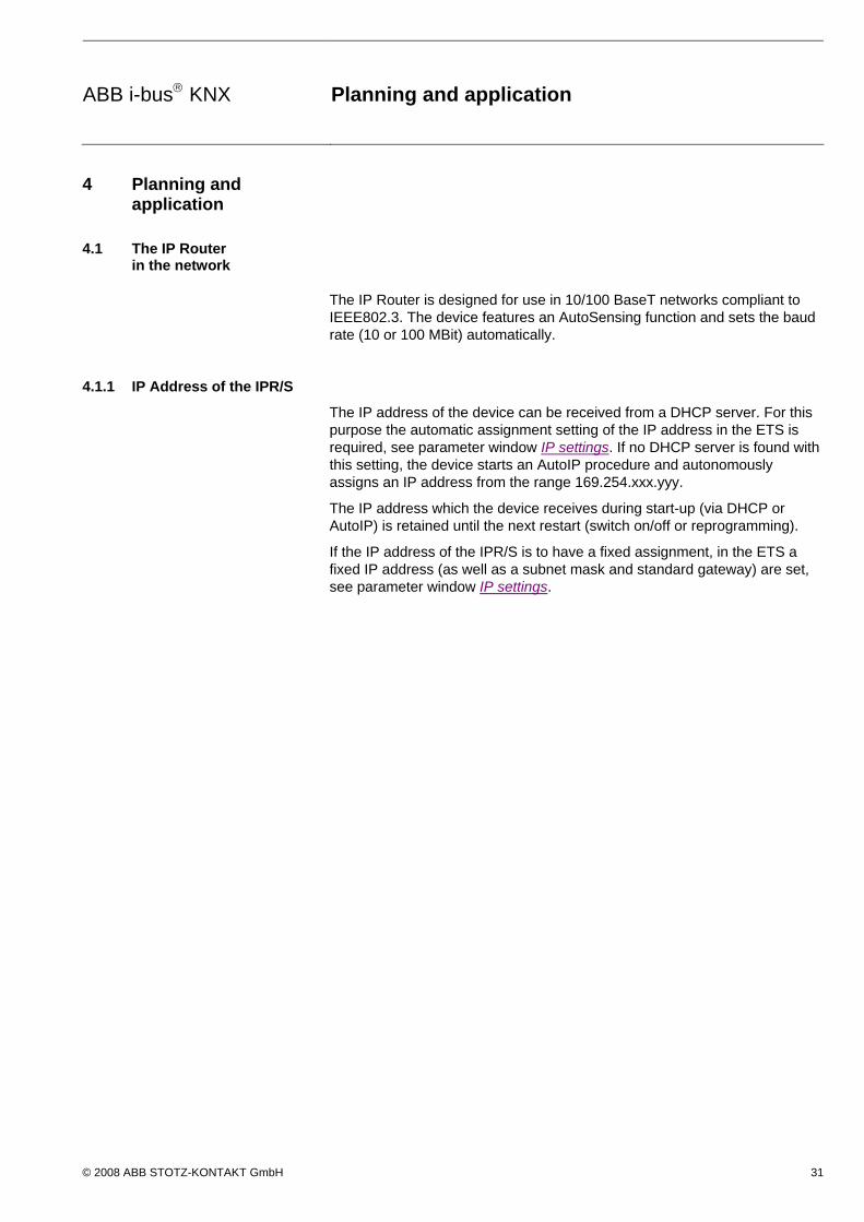
ABB i-bus KNX Planning and application
© 2008 ABB STOTZ-KONTAKT GmbH 31
4 Planning and application
4.1 The IP Router in the network
The IP Router is designed for use in 10/100 BaseT networks compliant to IEEE802.3. The device features an AutoSensing function and sets the baud rate (10 or 100 MBit) automatically.
4.1.1 IP Address of the IPR/S
The IP address of the device can be received from a DHCP server. For this purpose the automatic assignment setting of the IP address in the ETS is required, see parameter window IP settings. If no DHCP server is found with this setting, the device starts an AutoIP procedure and autonomously assigns an IP address from the range 169.254.xxx.yyy.
The IP address which the device receives during start-up (via DHCP or AutoIP) is retained until the next restart (switch on/off or reprogramming).
If the IP address of the IPR/S is to have a fixed assignment, in the ETS a fixed IP address (as well as a subnet mask and standard gateway) are set, see parameter window IP settings.

ABB i-bus KNX Planning and application
© 2008 ABB STOTZ-KONTAKT GmbH 32
4.1.2 KNX telegrams in the network
The IP Router sends telegrams from the KNX to the IP network in accordance with the KNXnet/IP protocol specification. These telegrams are sent in the default setting as multicast telegrams to the multicast IP address 224.0.23.12 port 3671. The Multicast IP address 224.0.23.12 is the defined address for the KNXnet/IP from the KNX Association in conjunction with IANA for KNX-IP devices. This address should be retained and only changed if the existing network demands that another address be used.
As several IP Routers in a network can communicate with one another, multicast communication must be possible between the devices. Depending on the type of network and the setting of the network components used, e.g. routers, switches or firewalls, the Multicast IP address 224.0.23.12 may need to be enabled explicitly beforehand. Please discuss the topic with your network administrator.
If no multicast communication is possible in a network, the IPR/S can also send Unicast telegrams to an IP address. This can be, e.g., the IP address of a PC on which the visualisation software is running. The communication is not compliant to the KNXnet/IP specification and currently only functions (date 08/2008) between ABB-IPR/S devices.
For further information see: Parameter window IP communication Unicast
Note
With the design of the KNX system it is important to note that the number of transferred telegrams is also limited when IP Routers are used. Due to the high baud rates on the IP side (10/100 Mbit/s), telegrams may be lost with high levels of data exchange for system reasons on the TP1 line (9.6 kbit/s).

ABB i-bus KNX Planning and application
© 2008 ABB STOTZ-KONTAKT GmbH 33
4.1.3 IPR/S as an area coupler
The IP Router in a KNX system can assume the function of an area coupler. For this purpose it must receive the physical address of an area coupler (1.0.0…15.0.0). At the present time in an ETS project (ETS3.0f) up to 15 areas can be defined with area couplers.
The following illustration shows the topology with IP Routers as area couplers and KNX line couplers (LK/S4.1).
G = KNX device LK = Line coupler
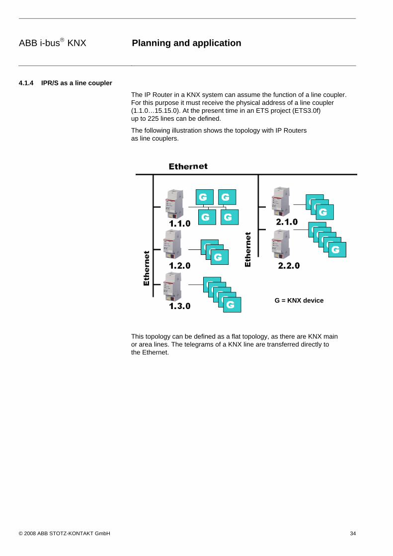
ABB i-bus KNX Planning and application
© 2008 ABB STOTZ-KONTAKT GmbH 34
4.1.4 IPR/S as a line coupler
The IP Router in a KNX system can assume the function of a line coupler. For this purpose it must receive the physical address of a line coupler (1.1.0…15.15.0). At the present time in an ETS project (ETS3.0f) up to 225 lines can be defined.
The following illustration shows the topology with IP Routers as line couplers.
This topology can be defined as a flat topology, as there are KNX main or area lines. The telegrams of a KNX line are transferred directly to the Ethernet.
G = KNX device

ABB i-bus KNX Planning and application
© 2008 ABB STOTZ-KONTAKT GmbH 35
4.1.5 Mixed topology
If it is necessary in a KNX system to use the IP Router at one point as an area coupler, e.g. office complex, and at another point as a line coupler, e.g. a remote underground garage; this is possible. It is only necessary to ensure that the IP Router used as a line coupler uses a line coupler address from a free area, e.g. in the illustration it is 2.1.0.
G = KNX device LK = Line coupler


ABB i-bus KNX Planning and application
© 2008 ABB STOTZ-KONTAKT GmbH 37
A Appendix
A.1 Ordering information
Short description Designation Order No. bbn 40 16779 EAN
Price group
Weight 1 pc. [kg]
Packaging [pc.]
IPR/S 2.1 IP Router, MDRC 2CDG 110 061 R0011 652 29 2 26 0.1 1

ABB i-bus KNX Planning and application
© 2008 ABB STOTZ-KONTAKT GmbH 38
A.2 Notes
ABB i-bus KNX Planning and application
© 2008 ABB STOTZ-KONTAKT GmbH 39
A.3 Notes

ABB i-bus KNX Planning and application
© 2008 ABB STOTZ-KONTAKT GmbH 40
A.4 Notes


ABB The technical details in this publication are subject to change without notice.
Pu
b. N
o. 2
CD
C 5
02
046
D0
202
Your EIB- Partner
Your KNX-Partner
www.abb.com/knx