Product Manual - ACL Staticide
12
ACL 850 Operation Manual Rev. March 11, 2011, mkb ACL Incorporated Tel: 847-981-9212 840 W. 49 th Place Page 1 of 12 [email protected] Chicago, IL 60609 USA www.aclstaticide.com ACL 850 Resistance Meter OPERATION MANUAL Meter is warranted for one year from the date of purchase on parts and labor. Calibration is recommended every twelve months.
Transcript of Product Manual - ACL Staticide

ACL 850 Operation Manual Rev. March 11, 2011, mkb
ACL Incorporated Tel: 847-981-9212 840 W. 49
th Place Page 1 of 12 [email protected]
Chicago, IL 60609 USA www.aclstaticide.com
ACL 850 Resistance Meter OPERATION MANUAL
Meter is warranted for one year from the date of purchase on parts and labor.
Calibration is recommended every twelve months.

ACL 850 Operation Manual Rev. March 11, 2011, mkb
ACL Incorporated Tel: 847-981-9212 840 W. 49
th Place Page 2 of 12 [email protected]
Chicago, IL 60609 USA www.aclstaticide.com
INTRODUCTION
The ACL 850 meter is an easy-to-use analog surface resistance tester. It is designed for measuring resistance of work surfaces and flooring in accordance with various standards including ANSI/ESDA S4.1 for Worksurface – Resistance Measurements and ANSI/ESDA S7.1 Resistive Characterization of Materials – Floor Materials. Please visit the ESD Association’s website for more information on ESD test standards: www.esda.org. The ACL 850 Analog Megohmmeter kit includes:
ACL 850 Analog Megohmmeter
Two test probes
Two connecting cables
One alligator clip
One 9-volt battery
One AAA battery
One steel plate for volume testing
Protective case
SAFETY PRECAUTIONS
Make sure unit is turned off while connect and disconnecting cables and electrodes.
Do not touch electrodes while measuring.
Do not use the unit to measure live circuits.
Do not touch the unit’s circuits.
Do not use accessories that are not included in the ACL 850 Analog Megohmmeter kit. Use of incompatible accessories will result in incorrect readings and damage the unit.
Take care to install batteries properly. Improper installation will result in unit malfunction.
Do not use in presence of strong electric or magnetic fields. These fields can distort accuracy.
Working temperature ranges from 0° to 40° С (32° – 104° F) at relative humidity not more than 75% at 30° С (86° F). The unit can be damaged if the values are beyond these limits.
ACL 850 Operation Manual Rev. March 11, 2011, mkb
ACL Incorporated Tel: 847-981-9212 840 W. 49
th Place Page 3 of 12 [email protected]
Chicago, IL 60609 USA www.aclstaticide.com
DISPLAY 1. “OHMS at 100V” scale Read the results of measurements from this scale when testing surfaces by using button “100V”. 2. “Test continuity / 10V” scale Read the results of measurements from this scale by depressing “Continuity / 10V” button in fixed position when measuring total resistance of test circuit (connecting cables, test electrodes on calibration plate) or surface resistance. 3. “Battery test” scale Read the results of measurements from this scale by using button “Battery test”. Values of the hand characterize working ability of the circuit and the condition of batteries. 4. “Continuity / 10V” button Depressing button in fixed position provides measurement mode at 10 V on test connectors. It allows either to test the integrity of measuring circuit and the quality of test electrodes or to measure surface resistance ranged from 100 Ohm to 1 Meg-Ohm. 5. “On/Off” switch When the button is in the position “On”, the power is supplied to the circuit. To save battery life, remember to turn button to “off” position after use.
6. Connection sockets of test electrodes The sockets are used to connect 5lb test electrodes to the unit with the help of connecting cables (included in the set). 7. Adjusting screw of the indicator hand Allow adjusting the initial position of the needle before switching on. Working position of the unit is horizontal. 8. “Battery test” button This button allows checking the correct work of the circuits and the condition of batteries. 9. “100V” button Fixation of the button provides 100 V on test connectors (not less than 100 V on electrodes at surface resistance 1 Meg-Ohm) and measurement of surface resistance ranged from 0,1 Meg-Ohm…100 Gig ohms.
Fig. 1
ACL 850 Operation Manual Rev. March 11, 2011, mkb
ACL Incorporated Tel: 847-981-9212 840 W. 49
th Place Page 4 of 12 [email protected]
Chicago, IL 60609 USA www.aclstaticide.com
PREPARATION
General Instructions
Read manual before putting unit into operation. Understanding how the unit works will help to avoid unnecessary mistakes and prolong service life of the unit.
Working Conditions
Working temperature ranges from 0 to 86°F at relative humidity not more than 75%. The unit can be damaged if the values are beyond these limits. The unit shouldn’t be used in environments with strong electric and magnetic fields. These fields can distort measuring accuracy.
Unpacking the unit
Check the packing case for possible damage. In case of possible damage, open the case and check the unit and accessories. Contact your supplier and forwarder if damages found.
If you consider the unit not to have any damages, read manual. Check all the accessories in the set.
Battery Installation
The unit is delivered with one 9-volt and one AAA battery, which ensure standard functioning. When installing and replacing the batteries:
Make sure that the unit is off.
Remove battery compartment cover.
Place the AAA battery into the opening and connect the 9-volt battery to the socket. Place the 9-volt battery and cables into the compartment so that you can easily place back the cover.
Replace the battery compartment cover.
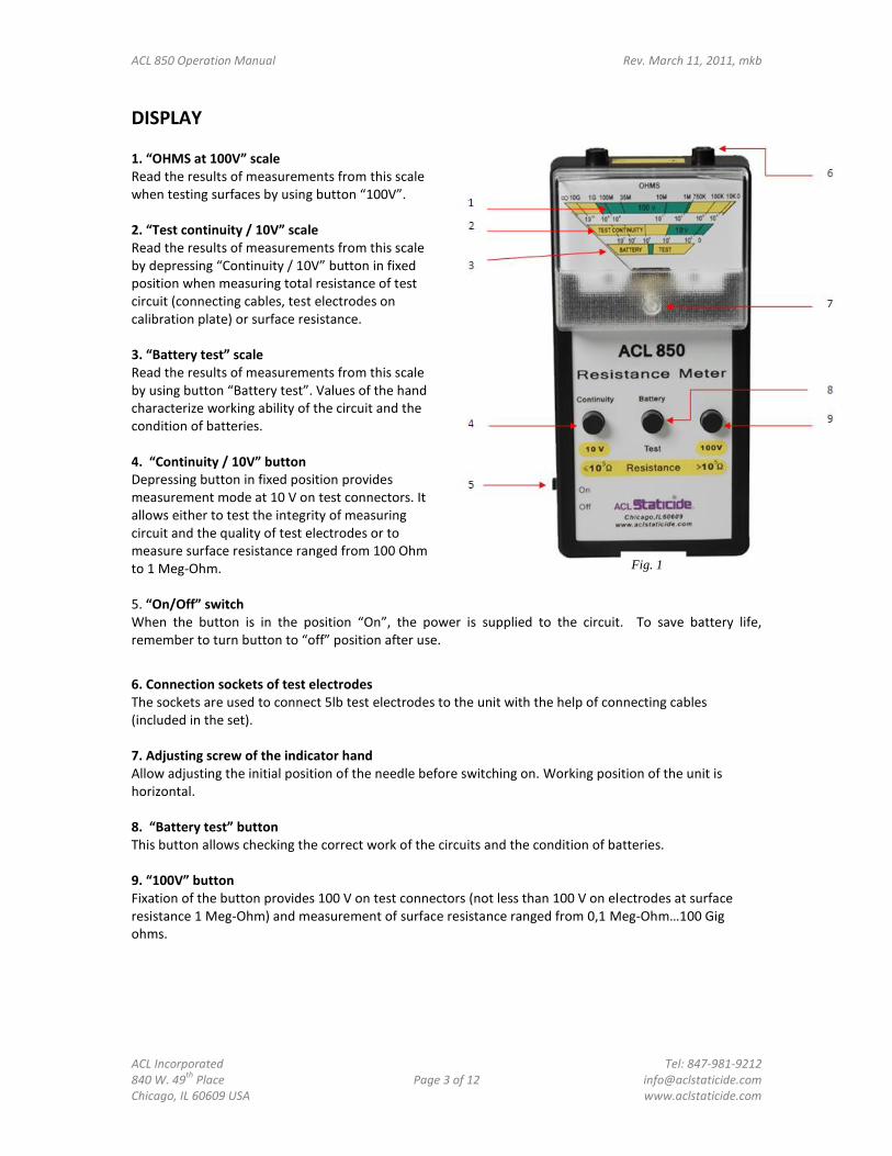
Check Indicator Needle
Make sure that the unit is off and place it on a horizontal surface. The hand of the unit should point at ∞. If the needle is not pointing at ∞, correct its position by turning the indicator adjusting screw.
Indicator hand or “needle”
Indicator adjusting screw
Fig. 2
ACL 850 Operation Manual Rev. March 11, 2011, mkb
ACL Incorporated Tel: 847-981-9212 840 W. 49
th Place Page 5 of 12 [email protected]
Chicago, IL 60609 USA www.aclstaticide.com
Battery Test
Turn the unit on. Press and hold the “Battery Test” button. The indicator needle should move to the green zone of the lower scale “Battery Test”. If the needle moves to the yellow zone to the left of the green zone (where it says “BATTERY”), the batteries should be replaced. If the needle moves to the yellow zone to the right of the green zone (where it says “TEST”), the unit should be sent to ACL for service.
Checking Operating Capacity
Put the switch button (#5, fig. 1) in the position “On”, press and hold the button “Battery test” (#8, fig. 1). The indicator hand should be in the green zone of the lower scale “Battery test”.
If the hand during the test is in the yellow zone which is to the left of the green zone in the lower scale, the batteries should be replaced. If it’s to the right of the green zone, the unit should be sent to the service center.
The unit switches on and power supply starts when the switch button is in the position “On”. Put the button into the position “Off” when the measurements are fulfilled.
Continuity Test
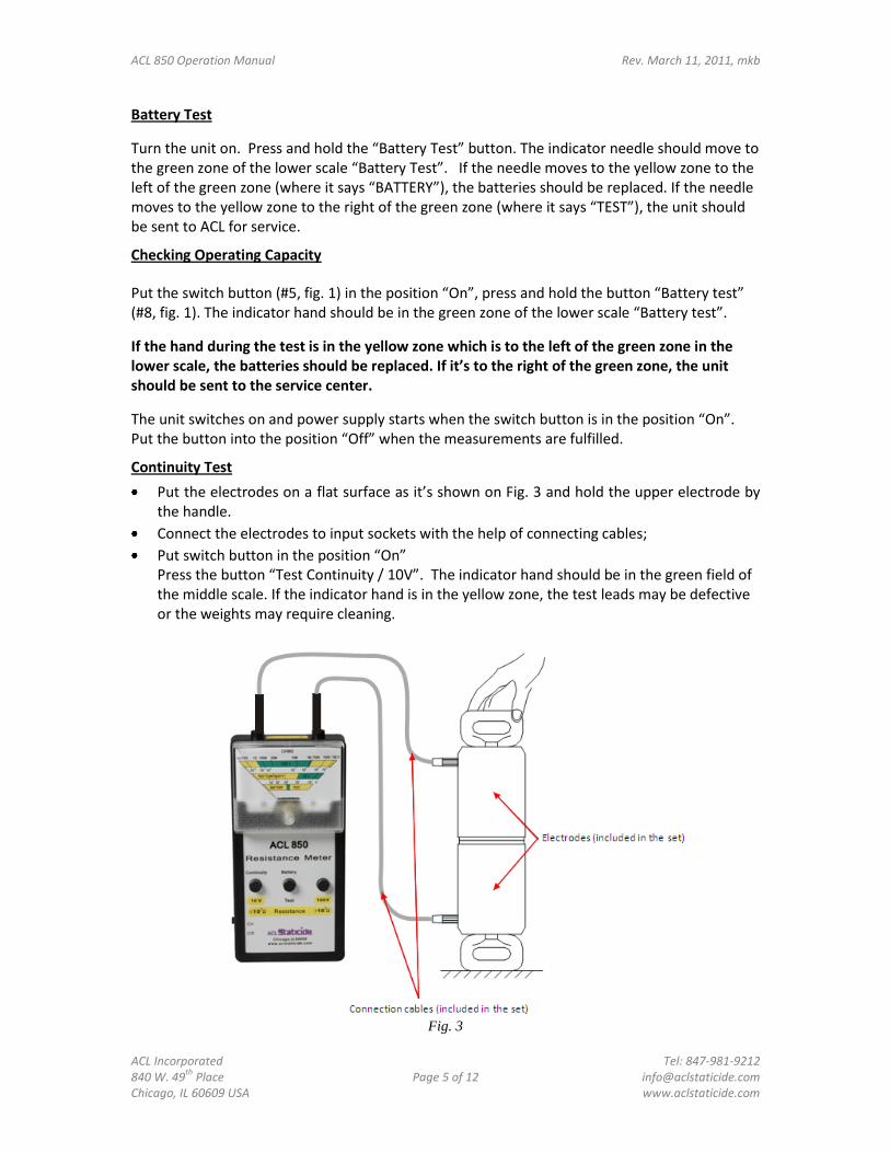
Put the electrodes on a flat surface as it’s shown on Fig. 3 and hold the upper electrode by the handle.
Connect the electrodes to input sockets with the help of connecting cables;
Put switch button in the position “On” Press the button “Test Continuity / 10V”. The indicator hand should be in the green field of the middle scale. If the indicator hand is in the yellow zone, the test leads may be defective or the weights may require cleaning.
Fig. 3
ACL 850 Operation Manual Rev. March 11, 2011, mkb
ACL Incorporated Tel: 847-981-9212 840 W. 49
th Place Page 6 of 12 [email protected]
Chicago, IL 60609 USA www.aclstaticide.com
OPERATION Operation Using External Probes
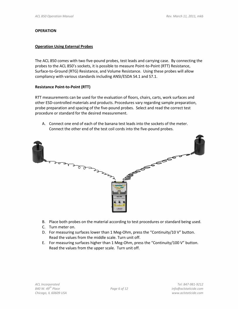
The ACL 850 comes with two five-pound probes, test leads and carrying case. By connecting the probes to the ACL 850’s sockets, it is possible to measure Point-to-Point (RTT) Resistance, Surface-to-Ground (RTG) Resistance, and Volume Resistance. Using these probes will allow compliancy with various standards including ANSI/ESDA S4.1 and S7.1. Resistance Point-to-Point (RTT) RTT measurements can be used for the evaluation of floors, chairs, carts, work surfaces and other ESD-controlled materials and products. Procedures vary regarding sample preparation, probe preparation and spacing of the five-pound probes. Select and read the correct test procedure or standard for the desired measurement.
A. Connect one end of each of the banana test leads into the sockets of the meter. Connect the other end of the test coil cords into the five-pound probes.
B. Place both probes on the material according to test procedures or standard being used. C. Turn meter on. D. For measuring surfaces lower than 1 Meg-Ohm, press the “Continuity/10 V” button.
Read the values from the middle scale. Turn unit off. E. For measuring surfaces higher than 1 Meg-Ohm, press the “Continuity/100 V” button.
Read the values from the upper scale. Turn unit off.
ACL 850 Operation Manual Rev. March 11, 2011, mkb
ACL Incorporated Tel: 847-981-9212 840 W. 49
th Place Page 7 of 12 [email protected]
Chicago, IL 60609 USA www.aclstaticide.com
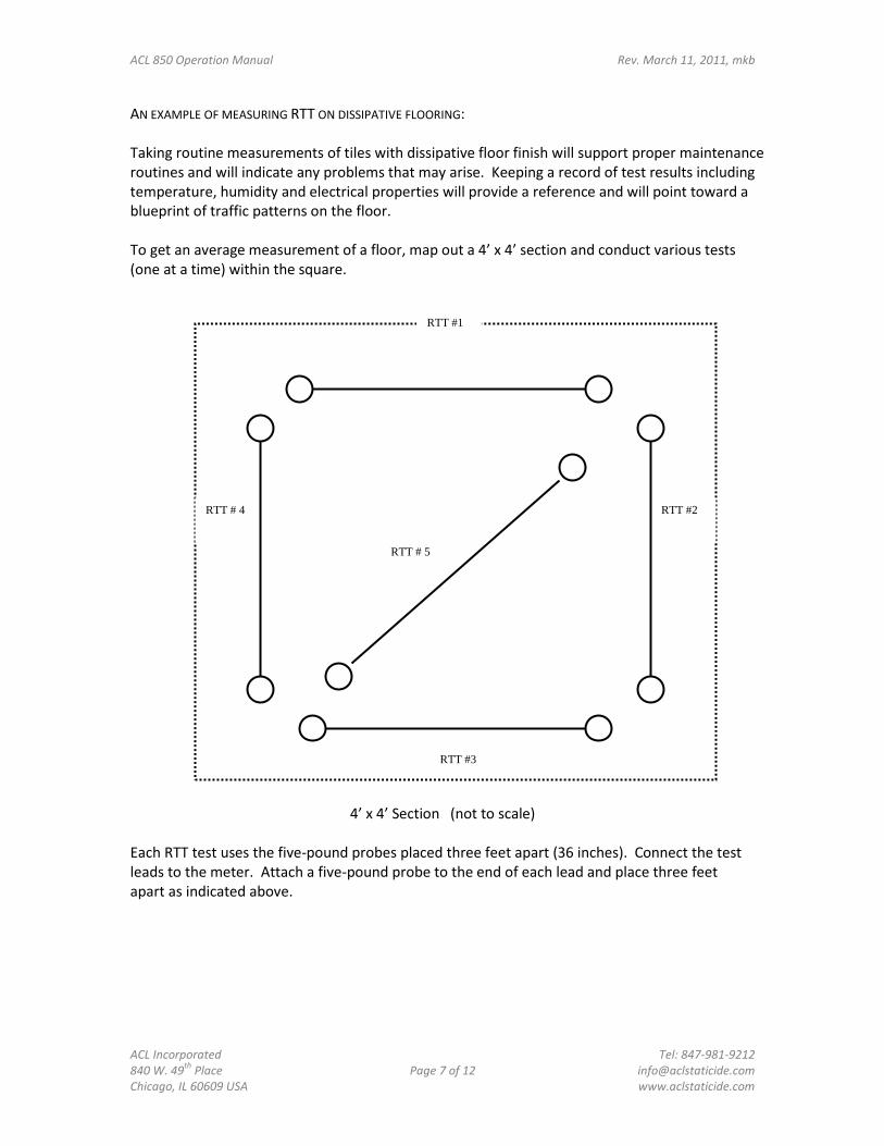
RTT #2 RTT # 4
AN EXAMPLE OF MEASURING RTT ON DISSIPATIVE FLOORING: Taking routine measurements of tiles with dissipative floor finish will support proper maintenance routines and will indicate any problems that may arise. Keeping a record of test results including temperature, humidity and electrical properties will provide a reference and will point toward a blueprint of traffic patterns on the floor. To get an average measurement of a floor, map out a 4’ x 4’ section and conduct various tests (one at a time) within the square.
4’ x 4’ Section (not to scale) Each RTT test uses the five-pound probes placed three feet apart (36 inches). Connect the test leads to the meter. Attach a five-pound probe to the end of each lead and place three feet apart as indicated above.
RTT #1
RTT #3
RTT # 5
ACL 850 Operation Manual Rev. March 11, 2011, mkb
ACL Incorporated Tel: 847-981-9212 840 W. 49
th Place Page 8 of 12 [email protected]
Chicago, IL 60609 USA www.aclstaticide.com
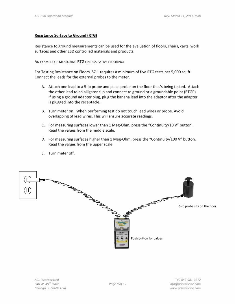
Resistance Surface to Ground (RTG)
Resistance to ground measurements can be used for the evaluation of floors, chairs, carts, work surfaces and other ESD controlled materials and products. AN EXAMPLE OF MEASURING RTG ON DISSIPATIVE FLOORING: For Testing Resistance on Floors, S7.1 requires a minimum of five RTG tests per 5,000 sq. ft. Connect the leads for the external probes to the meter.
A. Attach one lead to a 5-lb probe and place probe on the floor that’s being tested. Attach the other lead to an alligator clip and connect to ground or a groundable point (RTGP). If using a ground adapter plug, plug the banana lead into the adaptor after the adapter is plugged into the receptacle.
B. Turn meter on. When performing test do not touch lead wires or probe. Avoid overlapping of lead wires. This will ensure accurate readings.
C. For measuring surfaces lower than 1 Meg-Ohm, press the “Continuity/10 V” button. Read the values from the middle scale.
D. For measuring surfaces higher than 1 Meg-Ohm, press the “Continuity/100 V” button. Read the values from the upper scale.
E. Turn meter off.
5-lb probe sits on the floor
Push button for values
ACL 850 Operation Manual Rev. March 11, 2011, mkb
ACL Incorporated Tel: 847-981-9212 840 W. 49
th Place Page 9 of 12 [email protected]
Chicago, IL 60609 USA www.aclstaticide.com
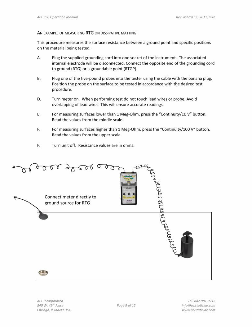
AN EXAMPLE OF MEASURING RTG ON DISSIPATIVE MATTING:
This procedure measures the surface resistance between a ground point and specific positions on the material being tested.
A. Plug the supplied grounding cord into one socket of the instrument. The associated internal electrode will be disconnected. Connect the opposite end of the grounding cord to ground (RTG) or a groundable point (RTGP).
B. Plug one of the five-pound probes into the tester using the cable with the banana plug. Position the probe on the surface to be tested in accordance with the desired test procedure.
D. Turn meter on. When performing test do not touch lead wires or probe. Avoid overlapping of lead wires. This will ensure accurate readings.
E. For measuring surfaces lower than 1 Meg-Ohm, press the “Continuity/10 V” button. Read the values from the middle scale.
F. For measuring surfaces higher than 1 Meg-Ohm, press the “Continuity/100 V” button. Read the values from the upper scale.
F. Turn unit off. Resistance values are in ohms.
Connect meter directly to ground source for RTG

ACL 850 Operation Manual Rev. March 11, 2011, mkb
ACL Incorporated Tel: 847-981-9212 840 W. 49
th Place Page 10 of 12 [email protected]
Chicago, IL 60609 USA www.aclstaticide.com
Connect alligator clip to snap for RTGP
If you are testing RTGP on an ESD mat, you can attach the alligator clip to the lead and connect it to the ground snap or connect the banana plug to a common point ground plug:
To Ground

ACL 850 Operation Manual Rev. March 11, 2011, mkb
ACL Incorporated Tel: 847-981-9212 840 W. 49
th Place Page 11 of 12 [email protected]
Chicago, IL 60609 USA www.aclstaticide.com
Volume Resistance Measurement Volume Resistance measures the electrical path through a material. A. Connect one end of each of the banana test leads into the sockets of the meter.
Connect the other end of the test coil cords into the five-pound probes. B. Place sample material on a conductive metal plate (such as stainless steel). Place one of
the five-pound probes on the material so that the material is sandwiched between the probe and metal plate. (See below.)
C. Place the second five-pound probe on the conductive metal plate. G. Turn meter on. H. For measuring surfaces lower than 1 Meg-Ohm, press the “Continuity/10 V” button.
Read the values from the middle scale. I. For measuring surfaces higher than 1 Meg-Ohm, press the “Continuity/100 V” button.
Read the values from the upper scale. J. Turn unit off. Volume Resistance is in ohms-cm.
Test Material Conductive Plate

ACL 850 Operation Manual Rev. March 11, 2011, mkb
ACL Incorporated Tel: 847-981-9212 840 W. 49
th Place Page 12 of 12 [email protected]
Chicago, IL 60609 USA www.aclstaticide.com
MAINTENANCE To ensure proper function, the electrodes must be kept clean. The unit’s housing and electrodes may be cleaned with lint-free wipes such as ACL’s LF50 Lint-Free Wipes or MFC1 Microfiber Cloths. Avoid direct sunlight on the electrodes’ contact surface.
In case of malfunction, it is recommended to send meter back to the factory for repair. Repairs outside of the factory will void warranty. Calibrate meter annually.
STORAGE Turn of the unit when not in use. Always store the ACL 850 Analog Megohmmeter in the provided case. Recommended storage conditions are as follows: Short-term: Environmental temperature of 10°C (50°F) to 50°C (122°F) (up to 12 months)
Relative humidity (RH) up to 75% at temperature 30°C (85°F) and below without condensation of moisture.
RH up to 80% at temperature 25°C (77°F) and below without condensation of moisture.
Long-term: Environmental temperature of 5°C (41°F) to 40°C (104°F) (12+ months)
RH up to 80% at temperature 25°C (77°F) and below without condensation of moisture.
Turn unit on yearly to check operation.
SPECIFICATIONS Unit size: 170mm x 85mm x 35 mm (6.7” x 3.3” x 1.4”)
Unit weight: 300 g (10.6 oz)
Probe size: 120mm x63mm diameter (5.2” x 2.5”)
Probe weight: 2.5 kg (5.5 lb) ±10% Steel plate size: 150mm x 65mm x 1 mm (5.9” x 2.6” x .04”)
Cable length: Not less than 1500mm (5 ft)
Range: 103– 106 ohms @ 10v 104– 1011 ohms @ 100v
Test voltage: Up to 116v
Accuracy: ±3%