Product Data - utcccs-cdn. · PDF fileProduct Data Axis ™ Single-Duct ... 2 125 56 59 60...
28
© Carrier Corporation 2017 Form 35E-7PD Product Data Axis ™ Single-Duct Terminal Units For Variable Air Volume Systems Nominal 23 to 7100 cfm 35E Single-Duct Terminal Units for Variable Air Volume Systems a35-656 axis logo
-
Upload
truongkhanh -
Category
Documents
-
view
215 -
download
2
Transcript of Product Data - utcccs-cdn. · PDF fileProduct Data Axis ™ Single-Duct ... 2 125 56 59 60...

© Carrier Corporation 2017 Form 35E-7PD
Product DataAxis™
Single-Duct Terminal UnitsFor Variable Air Volume SystemsNominal 23 to 7100 cfm
35ESingle-Duct Terminal Units for Variable Air Volume Systemsa35-656
axis logo

2
Single-duct variable air volume (VAV) terminal units provide:• 22-gage galvanized steel, unit
casing lined with ½-in. dual-density fiberglass
• Optional 20-gage galvanized steel casing for additional strength and durability
• Casing and all optional liners meet UL 181 (Underwriters Laboratories) and NFPA 90A (National Fire Protection Association) requirements
Features/BenefitsCarrier’s 35E terminal units are among the most versatile single-duct products on the market today, offering a compact design with diverse control packages (pneumatic, analog, and direct digital control options).Flexible, high-performance unitsThe 35E unit single-duct variable air volume (VAV) unit provides cooling only or cooling with reheat to meet all your application needs. It is designed to allow maximum flexibility in configu-ration and control. The 35E unit is of-fered in 11 sizes with air delivery range from 23 to 7100 cfm. The basic model
is a compact, high-performance unit with a standard single blade damper. Damper blade incorporates a flexible gasket for tight airflow shutoff and op-erates over a full 90 degrees. Minimal leakage and effective use of reheat air-flow combine to assure optimum utili-zation of supplied airflow. The small size of the unit ensures an easy fit in most applications.
Application flexibilityUnits have round inlets through size 16 and a rectangular inlet for the largest size. All round inlets have a raised col-lar bead to ensure tight inlet duct con-nections. All round collars accommo-date standard spiral and flex duct sizes. The 35E unit has a rectangular slip and drive connection on the discharge for quick installation. The units can be specified with electric or hot water heat, a number of linings, and sound attenuator.
Superior control offeringsEach 35E unit is supplied with a 4-quadrant linear-flow sensor as a stan-dard feature. This sensor is a 12-point total pressure sensor with center aver-aging. Balancing taps are provided to allow for easy airflow verification.
Control offerings include pressure independent pneumatic, analog elec-tronic, pressure independent VAV and pressure dependent VVT® (variable
volume and temperature) in both Carri-er i-Vu® Open (BACnet*) and Carrier Comfort Network® (CCN) protocols. Both VVT and VAV controls are com-municating Product Integrated Con-trols (PIC).
Pneumatic control units utilize a standard linear damper actuator, which, when combined with the 90-de-gree damper actuator, allows a simple switchover from normally open to nor-mally closed applications without mov-ing any components.
Analog and direct digital controls (DDC) electronic control units feature a factory-installed enclosure that pro-vides easy access for field connections. Control enclosure location matches unit hand (left or right).
Table of contentsPage
Features/Benefits . . . . . . . . . . . . . . . . . . . . . . . . . . . . . . . . . . . . . . . . . . . 2Model Number Nomenclature . . . . . . . . . . . . . . . . . . . . . . . . . . . . . . . . . . 3AHRI Ratings. . . . . . . . . . . . . . . . . . . . . . . . . . . . . . . . . . . . . . . . . . . . . . 4Physical Data . . . . . . . . . . . . . . . . . . . . . . . . . . . . . . . . . . . . . . . . . . . . . . 5Factory-Installed Options. . . . . . . . . . . . . . . . . . . . . . . . . . . . . . . . . . . . 6,7Dimensions . . . . . . . . . . . . . . . . . . . . . . . . . . . . . . . . . . . . . . . . . . . . 8-12Selection Procedure . . . . . . . . . . . . . . . . . . . . . . . . . . . . . . . . . . . . . . . . 13Performance Data . . . . . . . . . . . . . . . . . . . . . . . . . . . . . . . . . . . . . . 13-20Electrical Data . . . . . . . . . . . . . . . . . . . . . . . . . . . . . . . . . . . . . . . . . 21,22Application Data . . . . . . . . . . . . . . . . . . . . . . . . . . . . . . . . . . . . . . . . . . 23Guide Specifications . . . . . . . . . . . . . . . . . . . . . . . . . . . . . . . . . . . . . 24,25
*BACnet is a registered trademark of ASHRAE(American Society of Heating, Refrigerating andAir-Conditioning Engineers)

3
Unit StyleE – Single Duct
Control TypeA – Analog ControlsB – Open VVT®C – VAV CCND – Open VAVN – No ControlsP – PneumaticV – VVT® CCN
35E C 3 3 0 0L 12 0 4141 00 000 0000 E62 05.0 00000 080004000400000
Flow Sensor Type3 – Four Quadrant Liner
Unit Style0 – Base Unit1 – Attenuator Unit3 – Electric Heat Unit 3 – (Attenuator)
Liner Type0 – 1/2" Fiberglass1 – 1" Fiberglass2 – Steriliner4 – SterilwallA – Perforated DoublewallF – 1/2" Cellular
0 – 22-Gage, No Access1 – 20-Gage, No Access2 – 22-Gage, Access3 – 20-Gage, Access
Inlet Diameter04 – 4" Round05 – 5" Round06 – 6" Round07 – 7" Round08 – 8" Round09 – 9" Round10 – 10" Round12 – 12" Round14 – 14" Round16 – 16" Round22 – 24" x 16" Rectangular
Outlet Type0 – Rectangular
Control CodeSee Price Pages
Actuator Style00 – Standard
Control Options*0 – None4 – DA Thermostat5 – RA Thermostat
Unit Options0 – NoneS – HangersD – Controls DisconnectE – Dust Tight EnclosureH – 120v/24v TransformerJ – 208v/24v TransformerK – 240v/24v TransformerL – 277v/24v Transformer
Hot Water Coil(Example: W21 = Right-hand, 1-row coil)000 – NoneW1 – Left HandW2 – Right Hand1 – 1 Row2 – 2 Row3 – 3 Row4 – 4 Row
Electric HeatInput kW
Electric Heat000 – NoneE1X – 120v/1Ph, X StagesE2X – 208v/1Ph, X StagesE3X – 240v/1Ph, X StagesE4X – 277v/1Ph, X StagesE6X – 208v/3Ph, X StagesE9X – 480v/3Ph, X Stages
L1X – 120v/1Ph, SSRL2X – 208v/1Ph, SSRL3X – 240v/1Ph, SSRL4X – 277v/1Ph, SSRL6X – 208v/3Ph, SSRL9X – 480v/3Ph, SSR
Heat Options0 – NoneC – Fuse BlockE – Chicago Code ConstructionK – Door Interlocking Fused DisconnectL – Door Interlocking Non-Fused DisconnectP – Hot Water Coil Vent & Drain
Unit AirflowMax CFM, Min CFM, Heat CFM(Example: 800 Max cfm, 400 Min cfm, and 400 Heat cfm)
LEFT0L1L2L3L
RIGHT0R1R2R3R
Unit Casing
LEGENDCCN — Carrier Comfort Network®
DA — Direct-ActingRA — Reverse-Acting SSR — Solid-State RelayVAV — Variable Air VolumeVVT — Variable Volume and Temperature
a35-648
* Shipped with unit for field installation.
Model number nomenclature
4
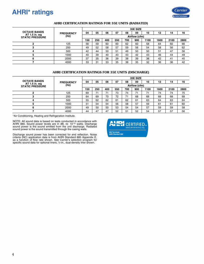
AHRI CERTIFICATION RATINGS FOR 35E UNITS (RADIATED)
AHRI CERTIFICATION RATINGS FOR 35E UNITS (DISCHARGE)
*Air Conditioning, Heating and Refrigeration Institute.
NOTE: All sound data is based on tests conducted in accordance withAHRI 880. Sound power levels are in dB, re: 10-12 watts. Dischargesound power is the sound emitted from the unit discharge. Radiatedsound power is the sound transmitted through the casing walls.
Discharge sound power has been corrected for end reflection. Noisecriteria (NC) application data is from AHRI Standard 885 Appendix E,as a function of flow rate shown. See Carrier’s selection program forspecific sound data for optional liners; ½-in., dual-density liner shown.
OCTAVE BANDS AT 1.5 in. wg
STATIC PRESSURE
FREQUENCY(Hz)
35E SIZE04 05 06 07 08 09 10 12 14 16
Airflow (cfm)150 250 400 550 700 900 1100 1600 2100 2800
2 125 56 59 60 60 62 60 58 64 60 663 250 49 52 58 57 59 56 54 58 56 624 500 42 44 50 51 49 50 50 51 47 565 1000 40 39 40 43 43 42 43 46 44 496 2000 37 35 36 39 38 39 38 42 41 457 4000 33 31 33 35 38 35 32 36 36 42
OCTAVE BANDS AT 1.5 in. wg
STATIC PRESSURE
FREQUENCY(Hz)
35E SIZE04 05 06 07 08 09 10 12 14 16
Airflow (cfm)150 250 400 550 700 900 1100 1600 2100 2800
2 125 69 71 71 73 74 71 71 74 74 753 250 64 69 70 72 71 68 68 68 68 684 500 55 62 62 61 62 61 63 64 63 645 1000 51 54 54 56 58 57 59 61 61 606 2000 49 50 50 53 54 54 57 59 59 587 4000 44 47 47 52 51 52 54 57 57 56
AHRI_CERT_880 VAV AIR TERMINAL K
AHRI* ratings

5
UNIT WEIGHTS
LEGEND
NOTE: Data is based on the following conditions:1. Unit casing is 22 gage.2. Unit insulation is ½-in. thick, 1.5-lb Tuf-Skin Rx* insulation, dual
density.3. Units rated with standard linear flow sensor.
RECOMMENDED AIRFLOW
* The standard minimum cfm value is based on a signal of 0.03 in. wgdifferential pressure of the inlet sensor. Minimum cfm may be 0. Theinlet sensor is capable of reading a signal down to 0.01 in. wg. To oper-ate unit below the standard minimum cfm values listed, DDC controllermust be capable to accurately read below 0.03 in. wg.
† Electric heat minimum is based on cfm necessary to engage airflowproving safety switch. Minimum cfm of unit will depend on the kWselected for that unit.
35E SIZE UNIT ONLY (lb)
WITH PNEUMATIC CONTROLS
(lb)
WITH DDC OR ANALOG CONTROLS
(lb)
WITH ELECTRIC HEAT (lb)
WITH HOT WATER(1 ROW/2 ROW)
(lb)04, 05, 06 14 +4 +9 +18 +5/+6
07, 08 16 +4 +9 +18 +5/+709, 10 21 +4 +9 +23 +7/+9
12 26 +4 +9 +25 +9/+1214 34 +4 +9 +27 +10/+1516 38 +4 +9 +28 +12/+1722 65 +4 +9 +30 +17/+25
DDC — Direct Digital Controls
INLET SIZE (in.) DESCRIPTION
MINIMUM CFM MAX PRIMARY AIRFLOW
(cfm)Standard* Electric Heat†
4 4-in. Round 40 55 2305 5-in. Round 62 85 3606 6-in. Round 89 110 5157 7-in. Round 121 140 7008 8-in. Round 159 190 9209 9-in. Round 201 240 1160
10 10-in. Round 248 300 143012 12-in. Round 357 425 206014 14-in. Round 486 580 280016 16-in. Round 634 750 366022 24- x 16-in. Rectangular 1212 1800 7000
Physical data
*Tuf Skin Rx is a trademark of Johns Manville.

6
Unit liner1. All liners are attached to the unit casing with both
adhesive and weld pins to ensure long-term durability(except Sterilwall and Perforated Doublewall).
2. Standard unit liner is ½-in. thick, 1½-lb density fiber-glass liner meeting UL 181 and NFPA 90A (orASTM84 and UL 723 Codes) requirements.
3. An optional 1-in. thick, 3-lb density fiberglass liner isavailable and meets UL 181 and NFPA 90A require-ments.
4. Optional Steriliner liner consists of rigid 13/16-in.,4-lb. density duct board insulation with nylon-rein-forced foil material covering the insulation fibers. Thelining is attached to the terminal unit casing by insula-tion adhesive and full-seam-length steel Z-strips,which enclose and seal the insulation edges, thuseliminating the need for tape and adhesives to coverthe cut edges.
5. Optional Sterilwall liner consists of standard ½-in.thick, blanket-type insulation, enclosed between theunit’s zinc-coated sheet metal casing and a non-perfo-rated internal zinc-coated sheet metal cover, whichextends over the fiberglass insulation, as well as thecut edges of the material.
6. Optional Cellular liner consists of a closed-cell elasto-meric thermal insulation that is ½-in or 1-in. thick,has a smooth surface, and is typically used in fiber-free applications.
7. Optional Perforated Doublewall liner consists of½-in., ½-lb dual-density fiberglass insulation, meetingUL 181 and NFPA 90A, enclosed between the unitcasing and a perforated internal sheet metal coverextending over the fiberglass insulation, as well ascovering the liner cut edges.
8. Unlined units are also available.
Access panelAn optional access panel in the terminal unit casing isavailable for viewing damper components and for up-stream cleaning of the hot water coil fins. Not available onunits with electric reheat or for size 22 units without the at-tenuator.
Hot water heat• Hot water coils are constructed of ten aluminum fins
per inch with 5/8-in. OD-sweat type, left or right-hand tubing connections.
• The coil tubing is water-leakage-tested to 400 psig.• Optional coils with vent and drain are available.
Packaging• Units with and without hot water coils are individually
packaged in a carton and stacked on a pallet.• Attenuated units and electric heat units are stacked
directly on the pallet. All pallets are banded and stretch-wrapped with cellophane.
Electric heat• Heaters are ETL-listed in accordance with UL standards
and are constructed of 20-gage galvanized steel.
• Heaters are available in single phase (120v, 208v, 240v, 277v or three phase (208/3 wire, 460v/4 wire).
• Standard heaters are equipped with primary automatic reset thermal cutout, de-energizing magnetic contac-tors, airflow proving switch, and 80/20 nickel chro-mium elements.
• Electric heater options include fused or non-fused door interlocking disconnect switch, proportional solid-state relay (SSR) heater control, discharge temperature sen-sor, manual reset thermal cut out, fuse block and dust tight control enclosure.
Control transformers• Units with electric heat and electronic controls (DDC or
Analog) include a factory supplied, mounted, and wired 24v control transformer. The control transformer is located inside the control enclosure and is used for pow-ering unit controllers, actuators, and accessories.
• Units without electric heat and with electronic controls (DDC or Analog) are available with an optional factory-installed 24v controls transformer.
Controls Factory-provided and installed pneumatic, analog, or directdigital controls are available. Units are available with no controls for field or factorymounting of field provided controls.
35EC – VAV CCN controls and 35ED – Open VAV controls• The VAV units are furnished with factory-installed PICs
for integration into either the Carrier Comfort Net-work® (35EC) or Carrier i-Vu® Open (35ED) Digital Control Systems.
• Each unit with Carrier VAV controls includes:• Control enclosure• Airflow sensor• VAV controller with integral actuator• Room temperature sensors are not included
35EV – VVT® CCN controls and 35EB – Open VVT® controls• The VVT units are furnished with factory-installed PICs
for integration into either the Carrier Comfort Network (35EV) or Carrier i-Vu Open VVT (35EB) Digital Con-trol Systems Constant
• Each unit with Carrier VVT controls includes:• Control enclosure• Airflow sensor• VAV controller with integral actuator
• Room temperature sensors are not included
35EA – Analog electronic controls• The Analog units are furnished standard with analog
controls by KMC. Consult the application drawings for control package details.
• Each Analog unit has pressure independent controls and includes:• Control enclosure• Airflow sensor• Digital thermostat• Damper actuator and analog controller
Factory-installed options

7
35EP – Pneumatic control units• The Pneumatic units are furnished standard with con-
trols by KMC. The standard 35EP unit includes control sequences that are pressure independent
• Each unit with Pneumatic controls includes:• Airflow sensor• Pneumatic damper actuator and volume reset
controller• Thermostats are not included in the standard control
packages. Pneumatic thermostats may be ordered in control accessory field.
35EN – No control units (factory-mounted actuator or field mounted)• The standard no control units are provided with the air-
flow sensor.• No control units are available with or without the con-
trol enclosure or transformer (Cooling Only or Cooling/Hot Water Heat).
• No control units with electric heat include control enclo-sure and transformer. Electric heaters may be ordered for use with 35EN units, but the field is responsible for assuring that controls that are supplied will provide proper airflow over the heater to avoid early failure.
• 35EN unit can have field provided controls and accesso-ries mounted and wired at the factory.
8
35E UNITSIZE
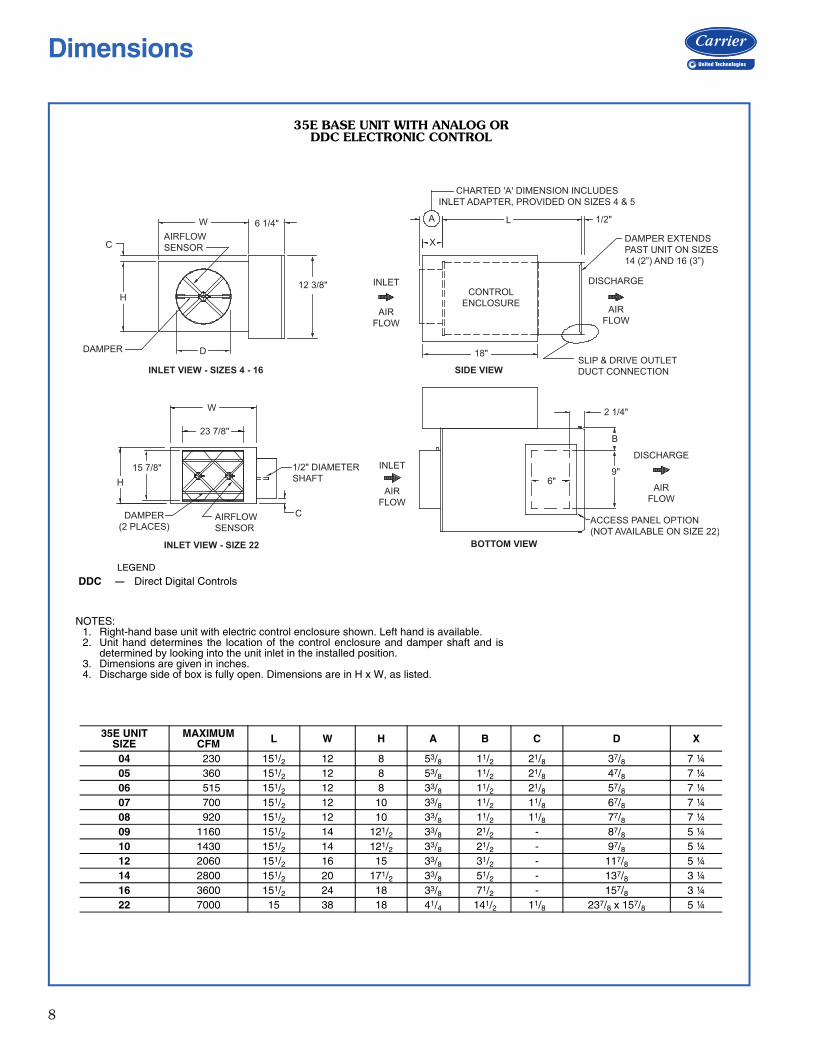
MAXIMUM CFM L W H A B C D X
04 230 151/2 12 8 53/8 11/2 21/8 37/8 7 ¼05 360 151/2 12 8 53/8 11/2 21/8 47/8 7 ¼06 515 151/2 12 8 33/8 11/2 21/8 57/8 7 ¼07 700 151/2 12 10 33/8 11/2 11/8 67/8 7 ¼08 920 151/2 12 10 33/8 11/2 11/8 77/8 7 ¼09 1160 151/2 14 121/2 33/8 21/2 - 87/8 5 ¼10 1430 151/2 14 121/2 33/8 21/2 - 97/8 5 ¼12 2060 151/2 16 15 33/8 31/2 - 117/8 5 ¼14 2800 151/2 20 171/2 33/8 51/2 - 137/8 3 ¼16 3600 151/2 24 18 33/8 71/2 - 157/8 3 ¼22 7000 15 38 18 41/4 141/2 11/8 237/8 x 157/8 5 ¼
35E BASE UNIT WITH ANALOG OR DDC ELECTRONIC CONTROL
NOTES:1. Right-hand base unit with electric control enclosure shown. Left hand is available.2. Unit hand determines the location of the control enclosure and damper shaft and is
determined by looking into the unit inlet in the installed position.3. Dimensions are given in inches.4. Discharge side of box is fully open. Dimensions are in H x W, as listed.
a35-651
W AIRFLOWSENSORC
DAMPER
6 1/4"
12 3/8"H
D
W
23 7/8"
15 7/8"H
DAMPER(2 PLACES)
AIRFLOWSENSOR
1/2" DIAMETERSHAFT
C
INLET
AIR FLOW
ACCESS PANEL OPTION(NOT AVAILABLE ON SIZE 22)
2 1/4"
B
9"6"
DISCHARGE
AIR FLOW
CHARTED 'A' DIMENSION INCLUDES INLET ADAPTER, PROVIDED ON SIZES 4 & 5
DAMPER EXTENDSPAST UNIT ON SIZES14 (2”) AND 16 (3”)
A
INLET
AIR FLOW
X
L 1/2"
DISCHARGE
AIR FLOW
CONTROL ENCLOSURE
18"SLIP & DRIVE OUTLET DUCT CONNECTION SIDE VIEW INLET VIEW - SIZES 4 - 16
INLET VIEW - SIZE 22 BOTTOM VIEW
LEGEND
DDC — Direct Digital Controls
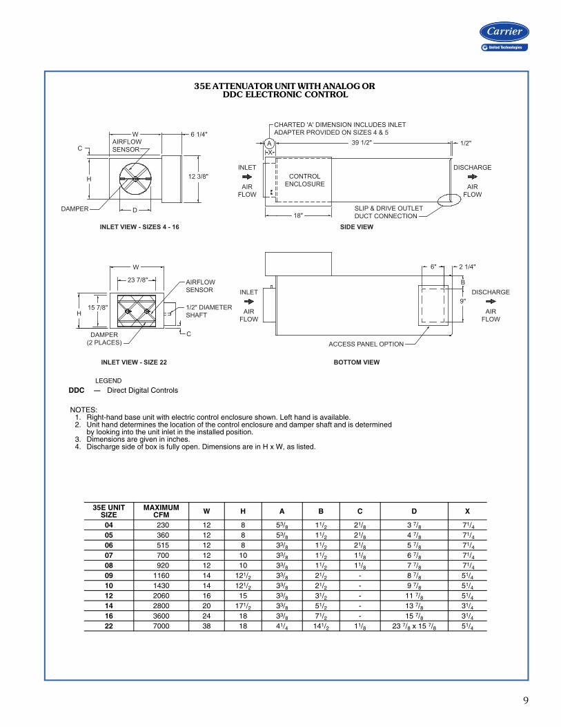
Dimensions
9
35E UNITSIZE
MAXIMUM CFM W H A B C D X
04 230 12 8 53/8 11/2 21/8 3 7/8 71/405 360 12 8 53/8 11/2 21/8 4 7/8 71/406 515 12 8 33/8 11/2 21/8 5 7/8 71/407 700 12 10 33/8 11/2 11/8 6 7/8 71/408 920 12 10 33/8 11/2 11/8 7 7/8 71/409 1160 14 121/2 33/8 21/2 - 8 7/8 51/410 1430 14 121/2 33/8 21/2 - 9 7/8 51/412 2060 16 15 33/8 31/2 - 11 7/8 51/414 2800 20 171/2 33/8 51/2 - 13 7/8 31/416 3600 24 18 33/8 71/2 - 15 7/8 31/422 7000 38 18 41/4 141/2 11/8 23 7/8 x 15 7/8 51/4
35E ATTENUATOR UNIT WITH ANALOG OR DDC ELECTRONIC CONTROL
NOTES:1. Right-hand base unit with electric control enclosure shown. Left hand is available.2. Unit hand determines the location of the control enclosure and damper shaft and is determined
by looking into the unit inlet in the installed position.3. Dimensions are given in inches.4. Discharge side of box is fully open. Dimensions are in H x W, as listed.
A35-652
CHARTED 'A' DIMENSION INCLUDES INLET ADAPTER PROVIDED ON SIZES 4 & 5
A X
INLET
AIR FLOW
INLET
AIR FLOW
CONTROL ENCLOSURE
18"
39 1/2" 1/2"
SLIP & DRIVE OUTLET DUCT CONNECTION
DISCHARGE
AIR FLOW
DISCHARGE
AIR FLOW
6" 2 1/4"
B
9"
ACCESS PANEL OPTION
C
DAMPER
H
W AIRFLOW SENSOR
6 1/4"
12 3/8"
D
H15 7/8"
W
23 7/8" AIRFLOWSENSOR
1/2" DIAMETERSHAFT
CDAMPER(2 PLACES)
INLET VIEW - SIZE 22
INLET VIEW - SIZES 4 - 16 SIDE VIEW
BOTTOM VIEW
LEGEND
DDC — Direct Digital Controls

10
DAMPER
H
CW
AIRFLOWSENSOR
6 1/4"
D
12"
INLET
AIRFLOW
INLET
AIRFLOW
DISCHARGE
AIRFLOW
A 39 1/2"
CHARTED 'A' DIMENSION INCLUDES INLETADAPTER PROVIDED ON SIZES 4 & 5
36 5/8"
PROVIDE CLEARANCE FOR CONTROLSAND REMOVAL OF HEATER RACK
PROVIDE CLEARANCE FOR CONTROLSAND REMOVAL OF HEATER RACK
B
1/2"
DISCHARGE
AIRFLOW
ELECTRONIC DAMPER & REHEAT CONTROLENCLOSURES
SLIP & DRIVEOUTLET DUCTCONNECTION
A 39 1/2" 1/2"
6 3/16" 32 5/8"
AIR FLOW SENSOR DAMPER(2 PLACES)
16 1/2"
C6 1/4"38"
23 7/8"
18"
INLET VIEW - SIZES 4 - 16
TOP VIEW - SIZES 4 - 16
TOP VIEW - SIZE 22
INLET VIEW - SIZE 22
15 7/8"
SLIP & DRIVE OUTLETDUCT CONNECTION
35E UNIT SIZE
MAXIMUM CFM W H A B C D
04 230 12 8 5 3/8 51/2 2 3 7/805 360 12 8 5 3/8 51/2 2 4 7/806 515 12 8 3 3/8 51/2 2 5 7/807 700 12 10 3 3/8 51/2 1 6 7/808 920 12 10 3 3/8 51/2 1 7 7/809 1160 14 121/2 3 3/8 31/2 - 8 7/810 1430 14 121/2 3 3/8 31/2 - 9 7/812 2060 16 15 3 3/8 31/2 - 11 7/814 2800 20 171/2 3 3/8 11/2 - 13 7/816 3600 24 18 3 3/8 11/2 - 15 7/822 7000 38 18 4 1/4 - 1 1/8 23 7/8 x 15 7/8
35E BASE UNIT WITH ELECTRIC HEAT AND ANALOG OR DDC ELECTRONIC CONTROL
NOTES:1. Right-hand base unit with electric control enclosure shown. Left hand is available.2. Unit hand determines the location of the control enclosure and damper shaft and is determined
by looking into the unit inlet in the installed position.3. Dimensions are given in inches.4. Units with electric heat coils automatically get the attenuator option. The overall length is
39½ inches.5. Check NEC (National Electrical Code) for unit clearance requirements.
A35-653
LEGEND
DDC — Direct Digital ControlsNEC — National Electrical Code
Dimensions (cont)

11
D
DA M P E R BL AD ES
1"
1"
W
C
H
DAMPER
AIRFLOWSENSOR
6 1/4"
12 3/8"
W
23 7/8"
H15 7/8"
AIRFLOWSENSOR
1/2" DIAMETERSHAFT
C
INLET
AIR FLOW
INLET
AIR FLOW
AIR FLOW
DISCHARGE
UNINSULATED COIL CASING
2 1/4"6"ACCESS PANEL OPTIONAL(NOT AVAILABLE ON SIZE 22)
9"
B
A
X
L Lc (SEE PAGE 12FOR DIMENSION)
CHARTED 'A' DIMENSION INCLUDES INLET ADAPTER PROVIDED ON SIZES 4 & 5
CONTROL ENCLOSURE
18" ACCESS PANEL OPTIONAL
DISCHARGE
WITH SLIP & DRIVE OUTLET DUCT CONNECTION
INLET VIEW - SIZES 4 - 16
INLET VIEW - SIZE 22 BOTTOM VIEW
SIDE VIEW
35E UNIT SIZE
MAXIMUM CFM L W H A B C D X
04 230 151/2 12 8 5 3/8 11/2 21/8 3 7/8 71/405 360 151/2 12 8 5 3/8 11/2 21/8 4 7/8 71/406 515 151/2 12 8 3 3/8 11/2 21/8 5 7/8 71/407 700 151/2 12 10 3 3/8 11/2 11/8 6 7/8 71/408 920 151/2 12 10 3 3/8 11/2 11/8 7 7/8 71/409 1160 151/2 14 121/2 3 3/8 21/2 - 8 7/8 51/410 1430 151/2 14 121/2 3 3/8 21/2 - 9 7/8 51/412 2060 151/2 16 15 3 3/8 31/2 - 11 7/8 51/414 2800 151/2 20 171/2 3 3/8 51/2 - 13 7/8 31/416 3600 151/2 24 18 3 3/8 71/2 - 15 7/8 31/422 7000 15 38 18 41/4 141/2 11/8 23 7/8 X 15 7/8 51/4
35E BASE UNIT WITH HOT WATER HEAT AND ANALOG OR DDC ELECTRONIC CONTROL
NOTES:1. Right-hand base unit with electric control enclosure shown. Left hand is available.2. Unit hand determines the location of the control enclosure and damper shaft and is deter-
mined by looking into the unit inlet in the installed position.3. Dimensions are given in inches.4. Discharge side of box is fully open. Dimensions are in H x W, as listed.
A35-654
LEGEND
DDC — Direct Digital Controls

12
Lc C
B H
1/2" A W 1"
35E UNIT SIZE
NO. OF ROWS IN
COILSH W Lc A B C WATER CONN
(OD)
04, 05, 06
1 Row 8 12 5 3 6 1/4 - 1/22 Row 8 12 5 41/4 6 7/8 11/8 7/83 Row 8 12 71/4 41/4 6 7/8 21/8 7/84 Row 8 12 71/4 41/4 6 7/8 31/4 7/8
07, 08
1 Row 10 12 5 3 8 3/4 - 1/22 Row 10 12 5 41/4 9 11/8 7/83 Row 10 12 71/4 41/4 9 21/8 7/84 Row 10 12 71/4 41/4 9 31/4 7/8
09, 10
1 Row 121/2 14 5 41/4 10 7/8 11/4 7/82 Row 121/2 14 5 41/4 111/2 11/8 7/83 Row 121/2 14 71/4 41/4 101/4 21/8 7/84 Row 121/2 14 71/4 41/4 101/4 31/4 7/8
12
1 Row 15 16 5 41/4 13 3/4 11/4 7/82 Row 15 16 5 41/4 13 3/4 11/8 7/83 Row 15 16 71/4 41/4 14 21/8 7/84 Row 15 16 71/4 41/4 14 31/4 7/8
14
1 Row 171/2 20 71/2 41/4 15 7/8 11/4 7/82 Row 171/2 20 71/2 41/4 161/2 11/8 7/83 Row 171/2 20 93/4 41/4 14 21/8 7/84 Row 171/2 20 93/4 41/4 14 31/4 7/8
16
1 Row 18 24 71/2 41/4 15 7/8 11/4 7/82 Row 18 24 71/2 41/4 161/2 11/8 7/83 Row 18 24 93/4 41/4 14 21/8 7/84 Row 18 24 93/4 41/4 14 31/4 7/8
22
1 Row 18 38 5 3 5/8 15 7/8 1 5/167/8
2 Row 18 38 5 3 5/8 161/2 1 3/327/8
3 Row 18 38 71/4 3 5/8 14 2 5/327/8
4 Row 18 38 71/4 3 5/8 14 3 1/4 7/8
35E HOT WATER COILS
NOTES: 1. 35E coils are shipped from the factory attached to the unit discharge. Coil discharge is configured for slip
and drive field ductwork installation. Coil section is uninsulated. Coils are not for steam applications.2. CONNECTION TUBING – 0.032-in. thick copper, male solder connection. Refer to connection diameter
shown in the table below.3. COIL CASING – 20-gage galvanized steel4. COIL TUBING – ½ in. OD x 0.016-in. thick copper5. COIL FINS – 0.0045-in. thick aluminum, 10 per inch, mechanically bonded to tubing.6. COILS ACCESSORIES – optional air vent and drain7. Unit dimensions given in inches
a35-655
Dimensions (cont)

13
Refer to the Carrier Air Terminal Builder program forinformation to determine unit sizing for your needs.
Performance data
DAMPER AND CASING LEAKAGE
NOTES: 1. Damper leakage is measured with the damper fully closed using
an actuator. A precision low-flow orifice is used upstream of theunit to measure the leakage rate as a function of the measuredupstream static pressure.
2. Casing leakage is determined with the damper fully open and thedischarge of the unit sealed. A precision low-flow orifice is usedupstream of the unit to measure the leakage rate as a function ofthe supplied static pressure. Leakage testing conducted in accor-dance with ASHRAE 130-2008.
UNIT SIZE35E
DAMPER LEAKAGE (cfm)
CASING LEAKAGE (cfm)
1.5 in. wg 3.0 in. wg 6.0 in. wg 0.5 in. wg 1.0 in. wg 1.5 in. wg 3.0 in. wg
04 4 5 7 2 3 4 5
05 4 5 7 2 3 4 5
06 4 5 7 2 3 4 5
07 4 5 7 4 5 6 9
08 4 5 7 4 5 6 9
09 4 5 7 4 6 7 10
10 4 5 7 4 6 7 10
12 4 5 7 5 7 9 12
14 4 6 8 6 9 11 16
16 5 7 9 7 10 13 17
Selection procedure

14
35E BASIC PRESSURE DATA
LEGEND
* The ASHRAE Handbook of Fundamentals does not recommend a dis-charge temperature exceeding 90 F for satisfactory air mixingand comfort.† A minimum of 0.10 in. discharge static pressure is required to ensuresteady operation for the airflow switch in the electric heater.**Max kW is limited by design.
NOTES:1. To obtain Total Pressure (Pt), add the Velocity Pressure for a given
cfm to the Static Pressure drop (PS) of the desired configuration, e.g., Pt for a Size 8 Basic Unit at 920 cfm = 0.39 + 0.17 = 0.56
2. Maximum discharge temperatures with electric heat are set at120 F by the National Electric Code.
3. Max kW shown assumes 55 F entering air and is limited by unit'sselected voltage, phase, max capacity and design. Min cfm forelectric heat is based on UL/ETL listings. (Diffuser performancewill likely be poor at this low flow rate).
4. Minimums for DDC by others are the responsibility of the controlsprovider.
INLET SIZE (in.) (Area in
sq ft)
MAXIMUM AIRFLOW
(cfm)
MINIMUM AIRFLOW (cfm)
ELECTRIC HEAT* MAX kW vs. CFM
at 55 F EAT
MINIMUM INLET STATIC PRESSURE (Unit and Heat Pressure Drop)
Cooling Only or with Hot
Water
Electric Heat
Velocity Press.(VPS)
Basic Unit(PS)
Basic + 1-Row Coil(PS)
Basic + 2-Row Coil(PS)
Basic + 3-Row Coil(PS)
Basic + 4-Row Coil(PS)
Basic + Heater†
(PS)
4 (0.09) 230 40 55
55 1.1 0.02 0.01 0.02 0.02 0.02 0.02 0.01110 2.2 0.10 0.05 0.06 0.07 0.08 0.09 0.05150 3** 0.18 0.10 0.12 0.13 0.15 0.16 0.10230 3** 0.43 0.24 0.28 0.31 0.35 0.39 0.24
5 (0.14) 360 62 85
85 1.7 0.02 0.01 0.02 0.02 0.03 0.03 0.01140 2.8 0.06 0.03 0.05 0.06 0.07 0.09 0.03250 5** 0.21 0.10 0.15 0.19 0.24 0.28 0.10360 5** 0.43 0.21 0.31 0.40 0.49 0.58 0.21
6 (0.20) 515 90 110
110 2 0.02 0.01 0.01 0.02 0.03 0.03 0.01250 5.1 0.10 0.04 0.09 0.13 0.17 0.22 0.04400 7.5** 0.25 0.10 0.22 0.34 0.45 0.56 0.10520 7.5** 0.42 0.17 0.38 0.57 0.75 0.94 0.17
7 (0.27) 700 121 140
140 2.9 0.02 0.01 0.01 0.02 0.03 0.04 0.01330 6.7 0.09 0.04 0.08 0.12 0.16 0.20 0.04550 9.5** 0.25 0.10 0.22 0.33 0.44 0.54 0.10700 9.5** 0.40 0.16 0.36 0.53 0.71 0.88 0.16
8 (0.35) 920 160 190
190 3.9 0.02 0.01 0.02 0.03 0.05 0.06 0.01440 9.1 0.09 0.04 0.12 0.19 0.25 0.32 0.04700 13** 0.23 0.10 0.29 0.47 0.64 0.82 0.10920 13** 0.39 0.17 0.51 0.81 1.11 1.42 0.17
9 (0.44) 1160 201 240
240 4.9 0.02 0.01 0.02 0.03 0.04 0.05 0.01550 11.3 0.08 0.04 0.09 0.14 0.19 0.24 0.04900 16** 0.23 0.10 0.25 0.38 0.52 0.66 0.10
1160 16** 0.38 0.17 0.42 0.64 0.86 1.09 0.17
10 (0.55) 1430 248 300
300 5.1 0.01 0.01 0.02 0.03 0.04 0.05 0.01700 14.3 0.08 0.04 0.13 0.21 0.29 0.38 0.04
1100 21** 0.21 0.10 0.32 0.53 0.73 0.93 0.101450 21** 0.36 0.17 0.56 0.91 1.26 1.62 0.17
12 (0.78) 2060 357 425
425 8.7 0.01 0.01 0.02 0.04 0.06 0.07 0.011000 20.6 0.08 0.04 0.14 0.22 0.31 0.40 0.041600 30** 0.20 0.10 0.35 0.57 0.80 1.02 0.102060 30** 0.33 0.17 0.58 0.95 1.32 1.69 0.17
14 (1.07) 2800 486 580
580 11.9 0.01 0.01 0.02 0.04 0.05 0.06 0.011375 28.2 0.07 0.04 0.13 0.21 0.28 0.36 0.042100 36** 0.16 0.10 0.30 0.48 0.66 0.84 0.102800 36** 0.29 0.18 0.53 0.85 1.17 1.49 0.18
16 (1.40) 3660 634 750
750 15.4** 0.01 0.01 0.02 0.04 0.06 0.07 0.011775 36** 0.06 0.04 0.14 0.22 0.31 0.40 0.042800 36** 0.14 0.10 0.34 0.56 0.77 0.99 0.103660 36** 0.24 0.17 0.58 0.95 1.32 1.69 0.17
22 (2.63) 7000 1212 1800
1800 36** 0.02 0.01 0.05 0.09 0.13 0.16 0.013300 36** 0.07 0.04 0.18 0.30 0.42 0.55 0.045300 36** 0.17 0.10 0.45 0.77 1.09 1.14 0.107000 36** 0.30 0.17 0.79 1.35 1.91 2.46 0.17
DDC — Direct Digital ControlsEAT — Entering Air TemperatureUL — Underwriters LaboratoriesPS — The difference in static pressure from inlet to dischargeVPS — Change in velocity pressure
Performance data (cont)

15
35E UNIT RADIATED SOUND POWER
LEGEND
* Pressure drop across damper only.
NOTES:1. Radiated sound power is the sound transmitted through the casing
walls.2. All sound data is based on tests conducted in accordance with
AHRI-880.3. Sound power levels are in dB, re: 10-12 watts.4. AHRI certification points are shown in shaded blocks.
35E UNIT SIZE
FLOW RATE MIN PS
0.75 IN. PS* 1.5 IN. PS* 2.5 IN. PS*Octave Band Sound Power, Lw LP Octave Band Sound Power, Lw LP Octave Band Sound Power, Lw LP
cfm in. wg 2 3 4 5 6 7 NC 2 3 4 5 6 7 NC 2 3 4 5 6 7 NC
04
50 0.011 37 28 24 23 17 10 - 38 29 27 25 19 15 - 38 30 30 27 21 18 - 110 0.054 50 42 34 33 30 23 - 51 43 38 35 32 28 - 51 45 40 37 34 31 - 150 0.100 55 47 39 37 35 29 - 56 49 42 40 37 33 - 56 50 45 41 39 37 - 230 0.235 62 55 45 43 42 36 24 62 57 48 45 44 40 26 53 58 51 47 46 44 27
05
60 0.006 38 21 17 12 8 6 - 43 26 22 15 11 12 - 47 30 26 18 14 17 140 0.031 47 36 30 26 22 17 - 52 41 35 29 25 23 - 56 45 39 32 28 28 250 0.100 53 47 39 36 31 25 - 59 52 44 39 35 31 20 62 55 47 41 38 36 25 360 0.207 57 53 44 42 37 30 21 62 58 49 45 41 36 27 66 62 53 47 44 41 31
06
100 0.006 43 35 24 15 10 6 - 46 40 28 20 16 13 - 49 44 31 24 20 19 - 250 0.039 52 47 38 28 23 19 - 56 52 43 33 29 26 - 58 55 46 37 33 32 24 400 0.100 57 53 46 35 30 26 21 60 58 50 40 36 33 27 63 61 53 43 40 38 31 520 0.169 60 56 50 39 34 29 25 63 61 54 43 39 37 30 65 64 57 47 43 42 35
07
120 0.005 38 42 25 17 12 7 - 42 47 31 21 16 14 - 44 51 35 24 19 19 - 330 0.036 50 48 38 31 27 22 - 54 54 44 36 31 28 22 57 58 49 39 34 33 27 550 0.100 5 52 45 39 34 29 - 60 57 51 43 39 35 26 62 61 55 46 42 40 31 700 0.162 59 53 48 42 38 32 23 63 59 54 46 42 38 29 66 63 49 50 45 43 34
08
160 0.005 45 39 27 22 18 16 - 48 45 34 27 23 23 - 50 49 39 30 27 28 - 440 0.040 55 49 38 33 28 26 - 58 54 45 38 33 33 23 60 59 50 41 37 38 28 700 0.100 59 53 43 38 32 31 21 62 59 49 43 38 38 28 64 63 55 46 41 43 33 920 0.173 52 56 45 41 35 34 24 65 52 52 46 40 41 31 67 66 57 49 44 46 37
09
200 0.005 37 36 21 22 21 19 - 42 42 26 26 26 27 - 44 47 29 29 30 33 - 550 0.037 50 45 38 33 30 24 - 54 51 42 37 35 32 - 56 56 45 40 39 38 25 900 0.100 56 49 46 38 34 27 - 60 56 50 42 39 35 24 62 60 53 45 43 41 301160 0.166 59 52 50 41 37 28 24 63 58 54 45 42 36 28 65 63 57 48 46 42 32
10
250 0.005 33 33 17 16 11 3 - 39 39 21 20 19 14 - 43 44 23 24 25 23 - 700 0.040 46 43 37 31 24 15 - 52 50 41 36 32 27 - 56 54 44 40 38 35 231100 0.100 52 48 46 38 30 21 20 58 54 50 43 38 32 24 62 59 52 46 44 41 281450 0.174 55 51 52 42 33 24 26 61 57 55 47 42 36 30 66 62 58 51 48 44 33
12
400 0.006 42 44 29 24 20 15 - 46 49 33 28 24 20 - 50 53 37 31 28 25 211000 0.039 54 50 41 36 32 25 - 58 55 45 40 36 31 23 61 58 48 43 40 35 271600 0.100 60 53 47 42 38 31 22 64 58 51 46 42 36 28 67 61 54 49 46 41 322060 0.166 63 55 50 45 41 33 26 67 59 54 49 46 39 32 71 63 58 52 49 43 36
14
480 0.005 35 35 19 24 21 18 - 39 40 22 27 24 22 - 43 44 25 30 27 26 -1375 0.043 50 46 37 36 33 28 - 54 51 40 39 37 32 - 58 55 43 42 39 36 242100 0.100 56 51 44 41 38 32 - 60 56 47 44 41 36 25 64 60 50 47 44 40 292800 0.178 60 54 49 44 41 34 23 65 59 52 48 45 39 28 68 63 55 50 47 42 33
16
630 0.005 38 36 29 28 25 22 - 43 43 34 33 32 30 - 47 48 38 37 38 36 -1775 0.040 54 49 44 39 34 30 - 59 56 49 44 41 38 25 61 61 53 48 47 44 312800 0.100 60 55 51 44 38 34 25 66 62 56 49 45 42 31 69 67 60 53 51 48 373660 0.171 64 58 55 47 41 36 30 70 65 60 52 48 44 36 73 70 64 55 53 50 42
22
1200 0.005 51 50 41 42 39 37 - 56 55 51 49 44 41 25 59 59 58 54 48 44 333300 0.039 65 61 55 53 51 47 30 69 66 65 60 56 51 41 73 69 73 99 60 54 495300 0.100 71 66 62 58 56 52 37 76 71 72 66 61 56 48 79 74 79 71 65 59 567000 0.174 75 69 66 62 59 55 42 80 74 76 69 65 59 52 83 77 83 74 69 61 60
AHRI — Air-Conditioning, Heating, and Refrigeration InstituteCFM — Air Volume (cubic feet per minute)LP — Room Sound PressureLW — Sound PowerMINPS— Minimum Static Pressure required to achieve rated airflowNC — Application Data from AHRI 885 Test conditionsPS — The difference in static pressure from inlet to discharge- — Indicates an NC level less than 20

16
35E UNIT DISCHARGE SOUND POWER
LEGEND
* Pressure drop across damper only.
NOTES:1. Discharge sound power is the sound emitted from the unit dis-
charge.2. All sound data is based on tests conducted in accordance with
AHRI 880.3. Sound power levels are in dB, re: 10-12 watts.4. AHRI certification points are shown in shaded blocks.
35E UNIT SIZE
FLOW RATE MIN PS
0.75 IN. PS* 1.5 IN. PS* 2.5 IN. PS*Octave Band Sound Power, Lw LP Octave Band Sound Power, Lw LP Octave Band Sound Power, Lw LP
cfm in. wg 2 3 4 5 6 7 NC 2 3 4 5 6 7 NC 2 3 4 5 6 7 NC
04
50 0.011 53 41 35 34 29 25 - 54 42 39 38 33 31 - 55 43 42 41 36 35 - 110 0.054 63 56 47 43 40 34 - 64 58 51 47 44 40 20 65 59 53 50 47 44 21 150 0.100 68 62 52 47 45 38 24 69 64 55 51 49 44 26 69 65 58 54 51 48 27 230 0.235 73 71 58 52 51 43 32 74 72 62 56 55 49 33 75 73 64 59 57 53 34
05
60 0.006 49 41 39 31 30 25 - 52 44 44 35 35 31 - 55 47 47 38 38 35 - 140 0.031 60 55 50 43 39 34 - 63 59 55 47 44 40 - 66 61 58 50 48 45 22 250 0.100 67 66 58 50 46 41 25 71 69 62 54 50 47 29 73 72 66 57 54 51 32 360 0.207 72 72 63 55 50 45 31 76 75 67 59 55 51 35 78 78 70 62 58 55 38
06
100 0.006 51 47 35 31 33 29 - 55 52 40 35 38 36 - 57 56 44 39 42 41 - 250 0.039 62 59 49 44 41 36 - 66 64 54 48 46 43 23 68 68 58 51 50 48 28 400 0.100 68 65 56 50 45 40 23 71 70 62 54 50 47 29 74 74 66 57 54 52 33 520 0.169 71 68 60 54 47 43 27 74 73 66 58 53 50 33 77 77 70 61 57 55 37
07
120 0.005 56 54 33 28 32 32 - 60 60 39 32 38 40 - 63 65 43 34 43 45 25 330 0.036 65 61 48 44 42 41 - 69 68 54 48 48 48 27 72 73 58 50 52 54 32 550 0.100 69 65 56 53 47 45 23 73 72 61 56 53 52 31 76 76 66 59 57 58 37 700 0.162 71 67 59 57 49 47 24 75 73 65 60 55 54 32 78 78 69 62 59 60 38
08
160 0.005 57 51 42 34 37 33 - 60 57 48 39 42 40 - 62 61 53 42 47 45 - 440 0.040 66 61 52 47 45 41 - 69 67 58 52 51 48 25 72 71 62 55 55 53 30 700 0.100 70 66 56 53 49 44 24 74 71 62 58 54 51 31 76 76 67 61 58 56 36 920 0.173 73 68 59 56 51 46 26 76 74 65 61 57 53 33 78 78 69 64 61 58 38
09
200 0.005 50 46 35 32 35 35 - 53 51 39 36 40 42 - 55 54 43 39 44 46 - 550 0.037 62 57 49 46 44 42 - 65 62 54 50 50 48 - 67 66 57 53 53 53 24 900 0.100 68 62 56 53 49 46 - 71 68 61 57 54 52 25 73 71 64 59 58 56 301160 0.166 72 66 60 56 52 47 23 74 71 65 60 57 53 29 76 74 68 63 60 58 33
10
250 0.005 50 48 40 38 39 37 - 53 53 45 42 45 43 - 55 57 48 45 49 48 - 700 0.040 62 58 52 49 48 45 - 65 63 57 54 53 51 21 68 67 61 57 57 55 261100 0.100 68 63 58 54 51 48 - 71 68 63 59 57 54 26 73 72 67 62 61 58 301450 0.174 71 66 61 58 53 50 23 74 71 66 62 59 56 29 77 74 70 65 63 61 33
12
400 0.006 52 47 39 42 42 42 - 56 52 43 46 47 48 - 58 56 46 50 50 52 -1000 0.039 64 58 53 52 50 48 - 68 63 57 56 55 54 - 70 67 60 60 58 58 241600 0.100 71 63 60 57 54 51 22 74 68 64 61 59 57 26 77 72 67 65 62 61 302060 0.166 74 66 63 59 56 52 26 78 71 68 64 61 58 30 80 75 71 67 64 63 34
14
480 0.005 47 44 33 39 38 40 - 50 48 37 43 42 46 - 52 52 39 46 45 50 -1375 0.043 64 58 53 52 50 48 - 67 62 56 56 54 54 - 69 65 58 59 57 58 222100 0.100 71 63 60 58 55 52 22 74 68 63 61 59 57 26 76 71 66 64 61 62 292800 0.178 75 67 66 61 58 54 28 78 71 69 65 62 60 32 81 75 71 68 65 64 35
16
630 0.005 41 37 22 31 30 29 - 44 41 26 34 35 34 - 47 45 28 37 38 38 -1775 0.040 62 55 49 48 46 44 - 65 60 52 52 51 50 - 68 63 55 55 54 54 -2800 0.100 71 63 60 56 53 51 23 75 68 64 60 58 56 27 77 71 66 63 61 60 303660 0.171 77 68 67 61 58 55 30 80 72 71 64 62 60 34 83 76 73 67 65 64 37
22
1200 0.005 67 57 55 50 46 38 - 73 65 58 55 51 44 25 78 70 60 59 55 49 313300 0.039 78 69 71 65 61 56 31 84 77 73 70 67 62 39 88 82 76 74 71 67 445300 0.100 83 75 78 72 69 65 37 89 82 81 77 74 71 45 93 88 83 81 78 76 517000 0.174 86 78 82 76 73 70 41 92 86 85 81 78 76 49 96 91 87 85 82 81 54
AHRI — Air-Conditioning, Heating, and Refrigeration InstituteCFM — Air Volume (cubic feet per minute)LP — Room Sound PressureLW — Sound PowerMINPS— Minimum Static Pressure required to achieve rated airflowNC — Application Data from AHRI 885 Test conditionsPS — The difference in static pressure from inlet to discharge- — Indicates an NC level less than 20
Performance data (cont)
17
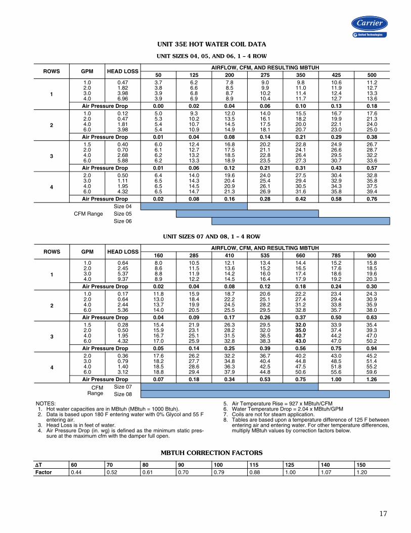
UNIT 35E HOT WATER COIL DATA
UNIT SIZES 04, 05, AND 06, 1 – 4 ROW
UNIT SIZES 07 AND 08, 1 – 4 ROW
NOTES:1. Hot water capacities are in MBtuh (MBtuh = 1000 Btuh).2. Data is based upon 180 F entering water with 0% Glycol and 55 F
entering air.3. Head Loss is in feet of water.4. Air Pressure Drop (in. wg) is defined as the minimum static pres-
sure at the maximum cfm with the damper full open.
5. Air Temperature Rise = 927 x MBtuh/CFM6. Water Temperature Drop = 2.04 x MBtuh/GPM7. Coils are not for steam application.8. Tables are based upon a temperature difference of 125 F between
entering air and entering water. For other temperature differences,multiply MBtuh values by correction factors below.
MBTUH CORRECTION FACTORS
ROWS GPM HEAD LOSSAIRFLOW, CFM, AND RESULTING MBTUH
50 125 200 275 350 425 500
1
1.02.03.04.0
0.471.823.986.96
3.73.83.93.9
6.26.66.86.9
7.88.58.78.9
9.09.9
10.210.4
9.811.011.411.7
10.611.912.412.7
11.212.713.313.6
Air Pressure Drop 0.00 0.02 0.04 0.06 0.10 0.13 0.18
2
1.02.04.06.0
0.120.471.813.98
5.05.35.45.4
9.310.210.710.9
12.013.514.514.9
14.016.117.518.1
15.518.220.020.7
16.719.922.123.0
17.621.324.025.0
Air Pressure Drop 0.01 0.04 0.08 0.14 0.21 0.29 0.38
3
1.52.04.06.0
0.400.702.685.88
6.06.16.26.2
12.412.713.213.3
16.817.518.518.9
20.221.122.823.5
22.824.126.427.3
24.926.629.530.7
26.728.732.233.6
Air Pressure Drop 0.01 0.06 0.12 0.21 0.31 0.43 0.57
4
2.03.04.06.0
0.501.111.954.32
6.46.56.56.5
14.014.314.514.7
19.620.420.921.3
24.025.426.126.9
27.529.430.531.6
30.432.934.335.8
32.835.837.539.4
Air Pressure Drop 0.02 0.08 0.16 0.28 0.42 0.58 0.76
CFM RangeSize 04Size 05Size 06
ROWS GPM HEAD LOSSAIRFLOW, CFM, AND RESULTING MBTUH
160 285 410 535 660 785 900
1
1.02.03.04.0
0.642.455.379.37
8.08.68.88.9
10.511.511.912.2
12.113.614.214.5
13.415.216.016.4
14.416.517.417.9
15.217.618.619.2
15.818.519.620.3
Air Pressure Drop 0.02 0.04 0.08 0.12 0.18 0.24 0.30
2
1.02.04.06.0
0.170.642.445.36
11.813.013.714.0
15.918.419.920.5
18.722.224.525.5
20.625.128.229.5
22.227.431.232.8
23.429.433.835.7
24.330.935.938.0
Air Pressure Drop 0.04 0.09 0.17 0.26 0.37 0.50 0.63
3
1.52.04.06.0
0.280.501.954.32
15.415.916.717.0
21.923.125.125.9
26.328.231.532.8
29.532.036.538.3
32.035.040.743.0
33.937.444.247.0
35.439.347.050.2
Air Pressure Drop 0.05 0.14 0.25 0.39 0.56 0.75 0.94
4
2.03.04.06.0
0.360.791.403.12
17.618.218.518.8
26.227.728.629.4
32.234.836.337.9
36.740.442.544.8
40.244.847.550.6
43.048.551.855.6
45.251.455.259.6
Air Pressure Drop 0.07 0.18 0.34 0.53 0.75 1.00 1.26
CFMRange
Size 07Size 08
T 60 70 80 90 100 115 125 140 150Factor 0.44 0.52 0.61 0.70 0.79 0.88 1.00 1.07 1.20

18
UNIT 35E HOT WATER COIL DATA (cont)
UNIT SIZES 09 AND 10, 1 – 4 ROW
UNIT SIZE 12, 1 – 4 ROW
NOTES:1. Hot water capacities are in MBtuh (MBtuh = 1000 Btuh).2. Data is based upon 180 F entering water with 0% Glycol and 55 F
entering air.3. Head Loss is in feet of water.4. Air Pressure Drop (in. wg) is defined as the minimum static pres-
sure at the maximum CFM with the damper full open. 5. Air Temperature Rise = 927 x MBtuh/CFM6. Water Temperature Drop = 2.04 x MBtuh/GPM
7. Coils are not for steam application.8. Tables are based upon a temperature difference of 125 F between
entering air and entering water. For other temperature differences,multiply MBtuh values by correction factors below.
MBTUH CORRECTION FACTORS
ROWS GPM HEAD LOSSAIRFLOW, CFM, AND RESULTING MBTUH
250 445 640 835 1030 1225 1400
1
1.02.03.04.0
0.110.410.901.56
11.012.312.813.1
13.916.217.117.6
15.818.820.020.8
17.220.722.323.2
18.222.324.125.2
19.023.625.726.9
19.724.626.928.2
Air Pressure Drop 0.02 0.05 0.09 0.14 0.20 0.27 0.33
2
1.02.04.06.0
0.270.471.844.08
17.918.820.421.0
24.125.829.030.3
28.130.635.237.2
31.034.140.142.6
33.236.844.047.1
35.039.047.350.9
36.340.749.853.9
Air Pressure Drop 0.04 0.10 0.19 0.29 0.42 0.56 0.70
3
2.03.04.06.0
0.360.801.413.14
23.424.625.225.8
32.835.537.038.6
39.043.245.548.2
43.548.952.155.8
46.953.557.562.1
49.657.261.967.4
51.660.065.271.5
Air Pressure Drop 0.06 0.15 0.28 0.44 0.63 0.84 1.05
4
2.53.04.06.0
0.460.661.162.58
26.927.428.028.7
39.240.542.344.1
47.649.852.756.0
53.856.760.865.4
58.562.167.373.2
62.366.572.679.8
65.169.876.684.8
Air Pressure Drop 0.08 0.21 0.38 0.59 0.84 1.12 1.40
CFM RangeSize 09Size 10
ROWS GPM HEAD LOSSAIRFLOW, CFM, AND RESULTING MBTUH
400 660 920 1180 1440 1700 1950
1
1.02.03.04.0
0.140.541.182.06
15.517.818.819.3
18.722.323.824.7
20.825.427.428.6
22.327.730.231.6
23.529.632.534.2
24.531.234.436.3
25.232.436.038.0
Air Pressure Drop 0.02 0.05 0.09 0.14 0.20 0.27 0.34
2
1.52.04.06.0
0.310.552.144.75
25.627.330.431.6
32.335.240.642.8
36.740.548.051.2
39.944.553.958.0
42.347.658.663.5
44.250.162.668.3
45.852.165.972.2
Air Pressure Drop 0.05 0.12 0.20 0.31 0.43 0.57 0.72
3
2.03.04.06.0
0.410.911.613.57
34.436.738.039.3
44.749.351.954.8
51.458.162.166.5
56.264.769.975.8
59.969.276.283.5
62.874.182.689.9
65.177.585.695.3
Air Pressure Drop 0.08 0.18 0.31 0.46 0.65 0.85 1.08
4
2.53.04.06.0
0.510.731.292.88
40.141.242.644.0
54.056.359.562.8
63.266.871.777.2
69.974.681.188.7
75.080.688.698.1
79.0 85.4 94.7106.0
82.2 89.2 99.6112.5
Air Pressure Drop 0.10 0.23 0.41 0.62 0.86 1.14 1.43
T 60 70 80 90 100 115 125 140 150Factor 0.44 0.52 0.61 0.70 0.79 0.88 1.00 1.07 1.20
Performance data (cont)

19
UNIT 35E HOT WATER COIL DATA (cont)
UNIT SIZE 14, 1 – 4 ROW
UNIT SIZE 16, 1 – 4 ROW
NOTES:1. Hot water capacities are in MBtuh (MBtuh = 1000 Btuh).2. Data is based upon 180 F entering water with 0% Glycol and 55 F
entering air.3. Head Loss is in feet of water.4. Air Pressure Drop (in. wg) is defined as the minimum static pres-
sure at the maximum cfm with the damper full open.
5. Air Temperature Rise = 927 x MBtuh/CFM6. Water Temperature Drop = 2.04 x MBtuh/GPM7. Coils are not for steam application.8. Tables are based upon a temperature difference of 125 F between
entering air and entering water. For other temperature differences,multiply MBtuh values by correction factors below.
MBTUH CORRECTION FACTORS
ROWS GPM HEAD LOSSAIRFLOW, CFM, AND RESULTING MBTUH
500 860 1220 1580 1940 2300 2650
1
1.02.03.04.0
0.110.430.961.70
19.122.724.225.1
23.028.531.132.6
25.432.435.837.8
27.035.339.441.9
28.337.642.345.1
29.339.444.647.8
30.040.946.650.1
Air Pressure Drop 0.02 0.04 0.08 0.12 0.18 0.24 0.30
2
2.03.04.06.0
0.390.861.513.36
34.036.938.640.4
44.149.452.656.2
50.657.962.467.6
55.264.269.976.6
58.869.175.883.9
61.573.180.790.0
63.876.484.795.2
Air Pressure Drop 0.04 0.10 0.17 0.27 0.38 0.50 0.64
3
2.53.04.06.0
0.510.731.292.88
44.946.448.250.2
60.163.167.371.9
69.774.280.587.7
76.5 82.2 90.3100.0
81.5 88.2 98.0109.9
85.4 92.9104.2118.1
88.5 96.7109.1124.8
Air Pressure Drop 0.06 0.15 0.26 0.40 0.57 0.75 0.95
4
3.54.05.06.0
0.710.921.432.05
52.653.554.855.6
73.675.979.181.4
87.7 91.2 96.6100.3
97.8102.5109.6114.9
105.4111.1119.9126.5
111.3117.9128.2136.0
116.0123.3134.9143.7
Air Pressure Drop 0.08 0.19 0.35 0.53 0.75 1.00 1.27
ROWS GPM HEAD LOSSAIRFLOW, CFM, AND RESULTING MBTUH
700 1135 1570 2005 2440 2875 3300
1
1.52.03.04.0
0.260.461.031.81
26.528.530.832.2
31.634.638.140.2
35.038.643.245.9
37.441.747.150.3
39.344.150.253.9
40.846.052.756.9
42.047.654.959.5
Air Pressure Drop 0.02 0.05 0.09 0.14 0.19 0.25 0.32
2
2.03.04.06.0
0.230.520.922.05
41.045.848.651.8
50.157.662.467.9
55.965.772.079.7
60.071.679.288.8
63.076.185.096.2
65.4 79.8 89.7102.3
67.4 82.8 93.5107.4
Air Pressure Drop 0.05 0.11 0.20 0.29 0.41 0.54 0.68
3
2.53.04.06.0
0.300.430.761.71
54.957.561.064.9
68.272.879.686.8
76.5 82.6 91.6102.5
82.2 89.6100.7114.5
86.4 94.8107.6124.1
89.7 98.9113.1131.9
92.2102.1117.6138.3
Air Pressure Drop 0.08 0.17 0.29 0.44 0.61 0.81 1.01
4
3.04.05.06.0
0.380.671.041.50
64.568.571.172.8
82.290.195.499.2
93.3104.5112.3118.0
101.0114.8124.8132.3
106.6122.6133.6143.6
110.9128.7142.1152.6
114.2133.5148.3160.0
Air Pressure Drop 0.10 0.23 0.39 0.59 0.82 1.07 1.35
T 60 70 80 90 100 115 125 140 150Factor 0.44 0.52 0.61 0.70 0.79 0.88 1.00 1.07 1.20

20
UNIT 35E HOT WATER COIL DATA (cont)
UNIT SIZE 22, 1 – 4 ROW
NOTES:1. Hot water capacities are in MBtuh (MBtuh = 1000 Btuh).2. Data is based upon 180 F entering water with 0% Glycol and 55 F
entering air.3. Head Loss is in feet of water.4. Air Pressure Drop (in. wg) is defined as the minimum static pres-
sure at the maximum cfm with the damper full open.
5. Air Temperature Rise = 927 x MBtuh/CFM6. Water Temperature Drop = 2.04 x MBtuh/GPM7. Coils are not for steam application.8. Tables are based upon a temperature difference of 125 F between
entering air and entering water. For other temperature differences,multiply MBtuh values by correction factors below.
MBTUH CORRECTION FACTORS
ROWS GPM HEAD LOSSAIRFLOW, CFM, AND RESULTING MBTUH
1250 2045 2840 3635 4430 5225 6000
1
1.52.03.04.0
0.320.571.262.21
39.843.948.851.7
46.252.059.263.6
50.257.166.271.8
53.060.871.378.0
55.063.775.482.9
56.665.978.787.0
57.967.781.390.3
Air Pressure Drop 0.03 0.06 0.11 0.17 0.24 0.32 0.41
2
2.03.04.06.0
0.260.581.022.28
60.970.776.884.0
71.6 86.2 95.9107.9
77.9 96.0108.4124.4
82.0102.8117.5136.7
85.1107.9124.4146.4
87.4111.9129.9154.4
89.2115.0134.3160.8
Air Pressure Drop 0.06 0.14 0.24 0.37 0.51 0.68 0.85
3
2.53.04.06.0
0.330.470.831.85
82.9 88.8 97.0106.3
97.8107.1120.9137.8
106.1117.7135.6158.8
111.4124.6145.7173.9
115.1129.6153.0185.5
117.9133.3158.7194.6
120.0136.2163.1201.9
Air Pressure Drop 0.09 0.21 0.36 0.55 0.77 1.01 1.28
4
3.04.05.06.0
0.400.711.111.59
99.0108.9115.3119.8
119.0136.0148.1156.9
130.0152.0168.5181.1
136.9162.6182.5198.2
141.6170.1192.7210.9
145.1175.8200.5220.7
147.7180.1206.6228.5
Air Pressure Drop 0.12 0.28 0.49 0.74 1.02 1.35 1.70
T 60 70 80 90 100 115 125 140 150Factor 0.44 0.52 0.61 0.70 0.79 0.88 1.00 1.07 1.20
Performance data (cont)

21
STAGED ELECTRIC HEAT kW RANGE PER INLET SIZE
HEATER CODE
DESCRIPTION (volts/phase/stages)
04 05 06 07 08 09
Min Max Min Max Min Max Min Max Min Max Min Max
E11 120v/1Ph/1S 0.5 3.0 0.5 5.0 0.5 5.0 0.5 5.0 0.5 5.0 0.5 5.0
E12 120v/1Ph/2S 1.0 3.0 1.0 5.0 1.0 5.0 1.0 5.0 1.0 5.0 1.0 5.0
E13 120v/1Ph/3S 1.5 3.0 1.5 5.0 1.5 5.0 1.5 5.0 1.5 5.0 1.5 5.0
E21 208v/1Ph/1S 0.5 3.0 0.1 5.0 0.1 7.5 0.1 9.5 0.1 9.5 0.1 9.5
E22 208v/1Ph/2S 1.0 3.0 1.0 5.0 1.0 7.5 1.0 9.5 1.0 9.5 1.0 9.5
E23 208v/1Ph/3S 1.5 3.0 1.5 5.0 1.5 7.5 1.5 9.5 1.5 9.5 1.5 9.5
E31 240v/1Ph/1S 1.0 3.0 1.0 5.0 1.0 7.5 1.0 9.5 1.0 11.0 1.0 11.0
E32 240v/1Ph/2S 1.5 3.0 1.5 5.0 1.5 7.5 1.5 9.5 1.5 11.0 1.5 11.0
E33 240v/1Ph/3S 2.0 3.0 2.0 5.0 2.0 7.5 2.0 9.5 2.0 11.0 2.0 11.0
E41 277v/1Ph/1S 1.0 3.0 1.0 5.0 1.0 7.5 1.0 9.5 1.0 13.0 1.0 13.0
E42 277v/1Ph/2S 1.5 3.0 1.5 5.0 1.5 7.5 1.5 9.5 1.5 13.0 1.5 13.0
E43 277v/1Ph/3S 2.5 3.0 2.5 5.0 2.5 7.5 2.5 9.5 2.5 13.0 2.5 13.0
E61 208v/3Ph/1S (3-Wire) 1.5 3.0 1.5 5.0 1.5 7.5 1.5 9.5 1.5 13.0 1.5 16.0
E62 208v/3Ph/2S (3-Wire) 1.5 3.0 1.5 5.0 1.5 7.5 1.5 9.5 1.5 13.0 1.5 16.0
E63 208v/3Ph/3S (3-Wire) 1.5 3.0 1.5 5.0 1.5 7.5 1.5 9.5 1.5 13.0 1.5 16.0
E91 480v/3Ph/1S (4-Wire) 2.5 3.0 2.5 5.0 2.5 7.5 2.5 9.5 2.5 13.0 2.5 16.0
E92 480v/3Ph/2S (4-Wire) 2.5 3.0 2.5 5.0 2.5 7.5 2.5 9.5 2.5 13.0 2.5 16.0
E93 480v/3Ph/3S (4-Wire) 2.5 3.0 2.5 5.0 2.5 7.5 2.5 9.5 2.5 13.0 2.5 16.0
HEATER CODE
DESCRIPTION (volts/phase/stages)
10 12 14 16 22
Min Max Min Max Min Max Min Max Min Max
E11 120v/1Ph/1S 0.5 5.0 0.5 5.0 1.0 5.0 1.0 5.0 1.0 5.0
E12 120v/1Ph/2S 1.0 5.0 1.0 5.0 2.0 5.0 2.0 5.0 2.0 5.0
E13 120v/1Ph/3S 1.5 5.0 1.5 5.0 3.0 5.0 3.0 5.0 3.0 5.0
E21 208v/1Ph/1S 0.5 9.5 0.5 9.5 1.0 9.5 1.0 9.5 1.0 9.5
E22 208v/1Ph/2S 1.0 9.5 1.0 9.5 2.0 9.5 2.0 9.5 2.0 9.5
E23 208v/1Ph/3S 1.5 9.5 1.5 9.5 3.0 9.5 3.0 9.5 3.0 9.5
E31 240v/1Ph/1S 1.0 11.0 1.0 11.0 1.0 11.0 1.0 11.0 1.0 11.0
E32 240v/1Ph/2S 1.5 11.0 1.5 11.0 2.0 11.0 2.0 11.0 2.0 11.0
E33 240v/1Ph/3S 2.0 11.0 2.0 11.0 3.0 11.0 3.0 11.0 3.0 11.0
E41 277v/1Ph/1S 1.0 13.0 1.0 13.0 1.0 13.0 1.0 13.0 1.5 13.0
E42 277v/1Ph/2S 1.5 13.0 1.5 13.0 2.0 13.0 2.0 13.0 3.0 13.0
E43 277v/1Ph/3S 2.5 13.0 2.5 13.0 3.0 13.0 3.0 13.0 4.5 13.0
E61 208v/3Ph/1S (3-Wire) 1.5 16.0 1.5 16.0 3.0 16.0 3.0 16.0 3.0 16.0
E62 208v/3Ph/2S (3-Wire) 1.5 16.0 1.5 16.0 3.0 16.0 3.0 16.0 3.0 16.0
E63 208v/3Ph/3S (3-Wire) 1.5 16.0 1.5 16.0 3.0 16.0 3.0 16.0 3.0 16.0
E91 480v/3Ph/1S (4-Wire) 2.5 21.0 2.5 21.0 3.0 36.0 3.0 36.0 4.5 36.0
E92 480v/3Ph/2S (4-Wire) 2.5 21.0 2.5 21.0 3.0 36.0 3.0 36.0 4.5 36.0
E93 480v/3Ph/3S (4-Wire) 2.5 21.0 2.5 21.0 3.0 36.0 3.0 36.0 4.5 36.0
Electrical data

22
PROPORTIONAL ELECTRIC HEAT kW RANGE PER INLET SIZE
NOTES:1. The ASHRAE handbook of fundamentals states that discharge
temperatures in excess of 90 F are likely to result in objectionableair temperature stratification in the space. Also, ventilation shortcircuiting may occur. ASHRAE Standard 62.1 limits discharge tem-peratures to 90 F or increasing the ventilation rate when heatingfrom the ceiling.
2. Electric heaters are provided as slip-in type integrally mounted tothe terminal unit.
Electric heat selection — Select heater so that pow-er (kW) is a whole number. Rounding to the nearest whole number has negligible impact on the discharge tempera-ture and power consumption.
Factors:A. Specify electric duct heaters using voltage, kW, and
number of steps.B. Required kW is calculated using the following rela-
tionship:
Where:Btuh = Required heating capacityCFM = Volume of air controlled during heating (typical-
ly 30-100% of maximum cooling volume)T = Leaving air temperature minus the entering air
temperature or the desired air temperature rise across the electric heater.
HEATER CODE VOLTAGE
04 05 06 07 08 09
Min Max Min Max Min Max Min Max Min Max Min Max
L1X 120v/1Ph 0.5 3.0 0.5 5.0 0.5 5 0.5 5.0 0.5 5.0 0.5 5.0
L2X 208v/1Ph 0.5 3.0 0.5 5.0 0.5 7.5 0.5 9.5 0.5 9.5 0.5 9.5
L3X 240v/1Ph 1.0 3.0 1.0 5.0 1.0 7.5 1.0 9.5 1.0 11.0 1.0 11.0
L4X 277v/1Ph 1.0 3.0 1.0 5.0 1.0 7.5 1.0 9.5 1.0 13.0 1.0 13.0
L6X 208v/3Ph (3 Wire) 1.5 3.0 1.5 5.0 1.5 7.5 1.5 9.5 1.5 10.5 1.5 10.5
L9X 480v/3Ph (4 Wire) 2.5 3.0 2.5 5.0 2.5 7.5 2.5 9.5 2.5 13.0 2.5 16.0
HEATER CODE VOLTAGE
10 12 14 16 22
Min Max Min Max Min Max Min Max Min Max
L1X 120v/1Ph 0.5 5.0 0.5 5.0 1.0 5.0 1.0 5.0 1.0 5.0
L2X 208v/1Ph 0.5 9.5 0.5 9.5 1.0 9.5 1.0 9.5 1.0 9.5
L3X 240v/1Ph 1.0 11.0 1.0 11.0 1.0 11.0 1.0 11.0 1.0 11.0
L4X 277v/1Ph 1.0 13.0 1.0 13.0 1.0 13.0 1.0 13.0 1.5 13.0
L6X 208v/3Ph (3 Wire) 1.5 10.5 1.5 10.5 3.0 10.5 3.0 10.5 3.0 10.5
L9X 480v/3Ph (4 Wire) 2.5 21.0 2.5 25.0 3.0 25.0 3.0 25.0 4.0 25.0
A35-649kW = Btuh
3413 kW = 3160
Electrical data (cont)

23
Several factors should be considered when selecting single-duct units. These include:
Airflow range — Carrier single-duct units are equippedwith a 4-quadrant, 12-point total pressure sensor in theunit inlet to allow pressure-independent control of airflowon the basis of a control signal. The flow range is limited bythe sensitivity of the controller employed, the inlet ductconditions, and the size of the selected unit. In most cases, inlet duct minimum airflow of less than500 fpm should be avoided to prevent erratic control. Aminimum flow less than 500 fpm results in differentialpressure signals less than 0.03 in. wg, which cannot beresolved reliably by most control systems. Carrier ComfortNetwork® (CCN) and Carrier i-Vu® Open controllers willallow a lower minimum cfm. Maximum inlet flow limits are typically restricted to lessthan 2500 fpm by duct pressure loss limitations, althoughacoustical limits may also limit selection above this range.
System pressure — Control of duct pressures is themost effective means of ensuring low sound levels, accu-rate flow control, and minimum energy use. For each ter-minal unit, there is a minimum static pressure differencerequired to assure delivery of the design airflow rate. Thepressure difference is measured across the terminal inlet todischarge and is reported in inches of water (in. wg). Theinlet pressure required by any given unit is the rated staticpressure plus the pressure requirements of the dischargeducts and outlets. Inlet static pressure is also a determiningcharacteristic for the sound level that can be anticipateddownstream from the terminal unit. The minimum inletstatic pressure shown in the terminal unit performancetables is the pressure required by a given size terminal unitto push a specified amount of airflow through the unit withthe damper wide open. The pressure was measured bytests conducted in accordance with AHRI Standard 880.
Acoustics — Two types of sound transmission are trace-able to air terminal units. “Radiated Sound” escapesthrough the casing walls and induced air ports offan-powered units, entering a room randomly. “DischargeSound” travels through the duct work and enters a roomvia the outlet. The most common method for analyzingthese sound levels is by the use of noise criteria (NC)curves. The curves cover a range of decibel (dB re: 10-12
watts) levels, per octave band, that are most recognizableto the human ear. These bands are designated 2 through7. (See “Sound Power [Lp] vs. Center Frequency” graph.)Equipment performance for VAV terminals is usually ratedin terms of sound power levels (Lw). Sound pressure ismeasured in a special acoustical chamber and then printedin sound tables in the form of sound power. Each terminalunit size, various static pressure levels, and flow capacitiesin both radiated (LwRAD) and discharge (LwDIS) are
recorded. By taking these ratings and subtracting variousattenuation factors, a sound pressure level (Lp) is arrivedat, which can be compared against the recommended NCvalues, as shown. For radiated sound power levels (LwRAD), the readingsfrom the acoustical chamber are measured and variousadjustments are then subtracted. NC is determined fromOctave Band Sound Power data with allowances for anenvironmental factor and a combined ceiling/space factorfor a typical mineral tile ceiling. The reductions are calcu-lated in accordance with AHRI 885-08 Appendix E, a pro-cedure for estimating occupied space sound levels in theapplication of air terminals and air outlets. Reductions usedto determine Discharge NC levels are different than that ofRadiated NC levels. AHRI 885 was modified in 1998 toreflect data obtained in ASHRAE sponsored research.For discharge sound power levels (LwDIS), NC was deter-mined from octave band sound power data with allowancesfor environmental factor, 5 ft of 1-in. lined duct matchingthe discharge dimension of the terminal, branch division,end reflection assuming 5 ft of 8-in. diameter flexible ductand room absorption based on a 2,500 ft3 room with anobserver 5 ft from the sound source. These reductions arecalculated in accordance with AHRI 885-08, Appendix E.End reflection loss accounts for low frequency soundreflecting from a room through a diffuser. The attenuationof frequencies through various sizes, shapes, and lengths ofduct is known as duct insertion and is a significant reduc-tion. Branching represents a reduction in sound as the airis divided into separate airstreams.
A35-650
SOUND POWER (Lp) VS. CENTER FREQUENCY
Application data

24
Single-Duct VAV Terminal UnitHVAC Guide Specifications
Size Range: Nominal 23 to 7100 cfmCarrier Model Number:
35EA (Analog Control)35EC (Carrier Comfort Network® [CCN] Variable Air Volume [VAV] Electronic Control)35ED (BACnet* VAV Electronic Controls)35EN (No Control or direct digital controls [DDC] by Others)35EP (Pneumatic Control)35EV (CCN Variable Volume and Temperature [VVT] Electronic Control)35EB (BACnet VVT Electronic Controls)
Part 1 — General1.01 SYSTEM DESCRIPTION:
Factory-assembled, externally powered, variable airvolume control terminal. Unit shall be complete witha damper assembly, flow sensor, externally mountedvolume controller, collars for duct connection, andall required features. Control box shall be clearlymarked with an identification label that lists suchinformation as nominal cfm, maximum and mini-mum airflow limits, coil-type and coil hand, whereapplicable.
1.02 QUALITY ASSURANCEA. Insulation shall meet National Fire Protection Asso-
ciation (NFPA) 90A requirements for flame spreadand smoke generation and Underwriters Laboratory(UL) 181 requirements for anti-erosion, corrosion,and fungus properties.
B. Hot water coils, when specified, shall be tested forleakage at 250 psig with the coil submerged inwater.
C. Electric heating coils, when specified, shall be UL orEngineering Testing Laboratory (ETL) listed anddesigned to comply with UL Standard 1096.
D. Sound power levels shall be Air-Conditioning, Heat-ing, and Refrigeration Institute (AHRI) certified inaccordance with the requirements of AHRI 880.
Part 2 — Products2.01 EQUIPMENT
A. General:Factory-assembled, externally powered, variable airvolume control terminal. Unit shall be complete witha damper assembly, flow sensor, externally mountedvolume controller, collars for duct connection and allrequired features. Control box shall be clearlymarked with an identification label that lists suchinformation as nominal cfm, maximum and mini-mum airflow limits, coil-type and coil hand, balanc-ing chart, and tagging data, where applicable.
B. Unit Cabinet:Constructed of 22-gage (20-gage optional) galva-nized steel with round or rectangular inlet collar andrectangular discharge with slip and drive connection.All primary air inlet collars shall accommodate stan-dard flex duct sizes
C. Insulation:1. Standard casing shall be lined with ½-in. thick,
½-lb dual-density fiberglass insulation thatmeets UL 181 and NFPA 90A. Insulation shallbe attached to the unit casing by adhesive andweld pins.
2. Optional Insulation:a. 1-in.-THICK INSULATION: Unit casing
shall be lined with dual-density, 1-in. thick,½-lb density fiberglass insulation that meetsUL 181 and NFPA 90A.
b. CELLULAR INSULATION: Unit casing shallbe lined with ½-in. or 1-in. thick, ½-lb den-sity, smooth surface, polyolefin, closed-cellfoam insulation for fiber-free application.Cellular insulation meets UL 181 and NFPA90A and does not support mold or bacteriagrowth. Insulation shall be attached to theunit casing by adhesive and weld pins.
c. STERILINER INSULATION: Unit casingshall be lined with 13/16-in. thick, 4-lb den-sity, rigid-board insulation with nylon-rein-forced foil covering insulation fibers thatmeets UL 181 and NFPA 90A. Liner shallbe attached to unit casing by adhesive andweld pins with full-seam-length Z-strips toenclose and seal the insulation cut edges.
d. NO LINER: Unit casing shall be equippedwith no internal insulation liner.
e. STERILWALL INSULATION: Unit casingshall be lined with ½-in. thick, ½-lb densityinsulation, meeting UL 181 and NFPA 90A,enclosed between the unit casing and a non-perforated internal sheet metal coverextending over the fiberglass insulation, aswell as covering the liner cut edges.
f. PERFORATED DOUBLE WALL: Unit cas-ing shall be lined with ½-in. thick, ½-lb dual-density fiberglass insulation that meets UL181 and NFPA 90A, enclosed between theunit casing and a perforated internal sheetmetal cover extending over the fiberglassinsulation, as well as covering the liner cutedges.
D. Damper Assembly:The control air damper assembly shall be con-structed of heavy gage galvanized steel with ½-in.solid shaft rotating in Delrin† bearings. Dampershaft shall be marked on the end to indicate damperposition. Damper blade shall incorporate a flexiblegasket for tight airflow shutoff and operate over afull 90 degrees.
Guide specifications
* BACnet is a registered trademark of ASHRAE (American Society ofHeating, Refrigerating and Air-Conditioning Engineers).†Delrin is a registered trademark of DuPont.

25
E. Controls:1. Units shall have pressure-independent pneu-
matic, analog, or communicating controls, asspecified, capable of maintaining required air-flow set points ±5% of the unit’s capacity at anyinlet pressure up to 6 in. wg. The controllersshall be capable of resetting between factory orfield-set maximum and minimum (>350 fpminlet duct velocity) set points to satisfy the roomthermostat demand.
2. The unit shall be equipped with an amplifiedflow probe located in the unit inlet. Air flow forthe pressure independent controller (suppliedby others) shall be determined with a factory-supplied 12-point total pressure, center-averag-ing cross flow sensor, having a magnificationresulting in no greater than 2625 fpm at 1 in.developed signal.
F. Special Features:1. Hot Water Heating Coil:
Coil shall be mounted in a minimum 20-ga. gal-vanized steel casing with slip and drive dis-charge connections and factory mounted on thebase unit as shown on the equipment drawings.Coils shall have:a. Aluminum fins (10 ft per in.) bonded to the
copper tubes by mechanical expansion. b. Number of coil rows and circuits shall be
selected to provide performance as requiredby the plans.
c. Up to 4 rows as shown on equipment draw-ings or designed on the equipment schedule.Right or left-hand fittings with sweat connec-tion sizes as indicated on equipment draw-ings.
2. Electric Heating Coil:Electric coils shall be supplied by the terminalunit manufacturer and shall be UL listed. Con-struct coil casing with minimum of 20-gagezinc-coated steel. Elements shall be
nickel-chrome and supported by ceramic isola-tors. The integral control panel shall be housedin a NEMA (National Electrical Manufacturers)1 enclosure, with access door to all controls andsafety devices. Electric coils shall contain a pri-mary automatic reset thermal cutout and differ-ential pressure airflow switch for proof ofairflow. Heaters shall: a. Be designed for the capacity, electrical char-
acteristics and steps of control as shown onthe equipment schedule
b. Have open coil construction with 80%nickel, 20% chromium wire supported infree-floating ceramic bushings. Coil frameshall be constructed of corrosion resistantsteel.
c. Be factory wired and include all limitswitches.
d. Have electric coils that shall include fused ornon-fused door interlocking disconnectswitch, alternating current (AC) solid staterelays (SSRs) for silent operation, fuse block,dust tight enclosure construction, allmounted and/or wired within the controlenclosure.
e. Have an SSR proportional control of electricheat that shall meet the requirements ofASHRAE (American Society of Heating,Refrigerating and Air-Conditioning Engi-neers) Standard 62, Addenda N.
f. Have an SSR proportional electronic con-trolled electric heater with control of theleaving air temperature limiting the unit dis-charge temperature to a set value.
3. Sound Attenuator:The integral sound attenuator section shall con-sist of a continuous extension of the standardzinc-coated steel casing. When electric heat isrequired, the attenuator will be used as a stan-dard feature.


Manufacturer reserves the right to discontinue, or change at any time, specifications or designs without notice and without incurring obligations.Pg 28 Catalog No. 04-52350009-01 Printed in U.S.A. Form 35E-7PD
Replaces: 35E-6PD
Carrier Corporation • Syracuse, New York 13221 3-17