Product Data Sheet: Rosemount 248 Wireless Temperature …/media/resources... · · 2016-01-19An...
18
Product Data Sheet March 2015 00813-0100-4248, Rev DA Standard temperature transmitter offers a wireless solution for process monitoring Optimize plant efficiency and increase measurement reliability with industry-proven capabilities and specifications Smart Wireless delivers innovative wireless solutions for temperature measurement and overall transmitter performance Explore the benefits of a Complete Point Solution from Rosemount Temperature Rosemount 248 Wireless Temperature Transmitter
-
Upload
nguyenhuong -
Category
Documents
-
view
214 -
download
0
Transcript of Product Data Sheet: Rosemount 248 Wireless Temperature …/media/resources... · · 2016-01-19An...

Product Data SheetMarch 2015
00813-0100-4248, Rev DA
Rosemount 248 Wireless Temperature Transmitter
Standard temperature transmitter offers a wireless solution for process monitoring
Optimize plant efficiency and increase measurement reliability with industry-proven capabilities and specifications
Smart Wireless delivers innovative wireless solutions for temperature measurement and overall transmitter performance
Explore the benefits of a Complete Point Solution from Rosemount Temperature

Rosemount 248 March 2015
Rosemount 248 Wireless Temperature Transmitter
Standard temperature transmitter offers a cost effective solution for wireless process monitoring
Single sensor capability with universal sensor inputs (RTD, T/C, mV, ohms)
IEC-approved WirelessHART® protocol
Large LCD display (only available with Enclosure Option Code P)
Optimize plant efficiency and increase measurement reliability with industry-proven capabilities and specifications
One-year stability rating reduces maintenance costs
User-centric Device Dashboards communicate important diagnostics and ensure process health
Open/short sensor diagnostics assist with detecting issues in the sensor loop
Compensation for ambient temperatures enhances transmitter performance
Four user-configurable alerts provide increased process information and measurement point insight (only available with Enclosure Option Code P)
Smart Wireless delivers innovative wireless solutions for temperature measurement and overall transmitter performance
Self-organizing network delivers information rich data with >99% data reliability and establishes a highly stable network
Smart Wireless capabilities extend the full benefits of PlantWeb® to previously inaccessible temperature measurement locations
Emerson SmartPower™ solutions provide an intrinsically safe Power Module, allowing field replacements without removing the transmitter from the process, keeping personnel safe and reducing maintenance costs
Emerson Process Management’s layered approach to wireless network security ensures that data transmissions are secure
Contents
Rosemount 248 Wireless Temperature Transmitter . . . . . . . . 2
Ordering Information . . . . . . . . . . . . . . . . . . . . . . . . . . . . . . . 4
Transmitter Specifications . . . . . . . . . . . . . . . . . . . . . . . . . . . . 6
Product Certifications . . . . . . . . . . . . . . . . . . . . . . . . . . . . . . 12
Dimensional Drawings . . . . . . . . . . . . . . . . . . . . . . . . . . . . . . 15
2 www.rosemount.com

Rosemount 248March 2015
Explore the benefits of a Complete Point Solution from Rosemount Temperature Measurement
An “Assemble To Sensor” option enables Emerson to provide a complete point temperature solution, delivering an installation-ready transmitter and sensor assembly
Emerson offers a selection of RTDs, thermocouples, and thermowells that bring superior durability and Rosemount reliability to temperature sensing, complementing the Rosemount Transmitter portfolio
Experience global consistency and local support from numerous worldwide Rosemount Temperature manufacturing sites
World-class manufacturing provides globally consistentproduct from every factory and the capacity to fulfill theneeds of any project, large or small
Experienced Instrumentation Consultants help select the right product for any temperature application and advise on best installation practices
An extensive global network of Emerson service and support personnel can be on-site when and where they are needed
Make wireless installation and configuration easy with the Emerson Smart Wireless Gateway.
For wireless applications that require superior accuracy, consider the Rosemount 648 Wireless Temperature Transmitter.
Explore how Emerson's intrinsically safe SmartPower Solutions reduce maintenance costs.
3www.rosemount.com

Rosemount 248 March 2015
Ordering Information
The Rosemount 248 Wireless temperature transmitter has a rugged wireless transmitter design and industry-proven capabilities and specifications.
Transmitter features include:
IEC-approved WirelessHART protocol (Option Code WA3)
Large LCD display (Option Code M5)
Internal Antenna (Option Code WP5)
3-Point Calibration Certificate (Option Code Q4)
Assemble to Sensor options (Option Code XA)
Table 1. Rosemount 248 Wireless Temperature Transmitter ordering information★ The Standard offering represents the most common options. The starred options (★) should be selected for best delivery.
__The Expanded offering is subject to additional delivery lead time.
Code Product description
248 Temperature Transmitter
Transmitter type
D Wireless Field Mount ★
Transmitter output
X Wireless ★
Product certifications
NA No Approval ★
I5 USA Intrinsically Safe and Non-incendive ★
N5(1) USA Nonincendive and Dust-Ignitionproof ★
I6 Canada Intrinsically Safe ★
I1 ATEX Intrinsic Safety ★
I7 IECEx Intrinsic Safety ★
I2(2) INMETRO Intrinsic Safety ★
I4(2) TIIS Intrinsic Safety ★
I3(2) NEPSI Intrinsic Safety ★
IM Technical Regulation Customs Union (EAC), Intrinsic Safety ★
Enclosure options Material IP rating
D Wireless Housing Aluminum IP66/67 ★
P Wireless Engineered Polymer Housing Engineered Polymer IP66/67 ★
Conduit entry size
2 1/2-14 NPT ★
4 www.rosemount.com

Rosemount 248March 2015
Options (include with selected model number)
Assemble to options
NS No Sensor ★
XA(3) Sensor Specified Separately and Assembled to Transmitter ★
Wireless update rate, operating frequency, and protocol
WA3 User Configurable Update Rate, 2.4GHz DSSS, WirelessHART ★
Omnidirectional wireless antenna and SmartPower
WP5(2)(4) Internal Antenna, Compatible with Green Power Module (I.S. Power Module sold separately) ★
WK1(1)(5) External Antenna, Adapter for Black Power Module (I.S. Power Module sold separately) ★
Mounting bracket
B5 Universal “L” Mounting Bracket for 2-in. pipe mounting - SST bracket and bolts ★
Display
M5(2) LCD Display ★
Cable gland option
G2 Cable Gland (7.5 mm - 11.9 mm) ★
G4 Thin Wire Cable Gland (3 mm - 8 mm) ★
5-point calibration
C4(1) 5-Point Calibration (Requires the Q4 option code to generate a Calibration Certificate) ★
Calibration certificate
Q4 Calibration Certificate (3-Point Calibration) ★
External ground
G1(1) External Ground Lug Assembly ★
Line filter
F5 50 Hz Line Voltage Filter ★
F6 60 Hz Line Voltage Filter ★
Software configuration
C1 Custom Configuration of Date, Descriptor, Message, and Wireless Parameters (Requires CDS with order) ★
Extended product warranty
WR3 3-year limited warranty ★
WR5 5-year limited warranty ★
Typical model number: 248 D X NA P 2 NS WA3 WP5 B5 M5 F6 WR3
(1) Only available with Enclosure Option Code D.
(2) Only available with Enclosure Option Code P.
(3) When ordering a Rosemount 248 wireless with the XA option, a mounting bracket is not included. If a bracket is required, order option code B5.
(4) Green Power Module must be shipped separately, order Model 701PGNKF.
(5) Black Power Module must be shipped separately, order Model 701PBKKF.
Table 1. Rosemount 248 Wireless Temperature Transmitter ordering information★ The Standard offering represents the most common options. The starred options (★) should be selected for best delivery.
__The Expanded offering is subject to additional delivery lead time.
5www.rosemount.com

Rosemount 248 March 2015
Transmitter Specifications
Functional specifications
Input
Supports Thermocouple, RTD, millivolt, and ohm input types. See “Accuracy” on page 9 for a full listing of sensor options.
Output
IEC 62591 (WirelessHART), 2.4 GHz DSSS.
Local display(1)
The optional five digit integral LCD display can display sensor temperature in engineering units (°F, °C, °R, K, Ω, and millivolts) and percent of range. The display updates based in the Wireless Update Rate.
Humidity limits
0-99% Non-condensing Relative Humidity
Update rate
WirelessHART, user selectable 1 sec. to 60 min.
Accuracy (Pt 100 @ reference condition: 20 °C)
±0.45 °C (±0.81 °F)
Wireless radio (WP5 and WK1 options)
Frequency: 2,400 - 2,485 GHzChannels: 15Modulation: IEEE 802.15.4 compliant DSSS
Physical specifications
Material selection
Emerson provides a variety of Rosemount product with various product options and configurations including materials of construction that can be expected to perform well in a wide range of applications. The Rosemount product information presented is intended as a guide for the purchaser to make an appropriate selection for the application. It is the purchaser’s sole responsibility to make a careful analysis of all process parameters (such as all chemical components, temperature, pressure, flow rate, abrasives, contaminants, etc.), when specifying product, materials, options and components for the particular application. Emerson Process Management is not in a position to evaluate or guarantee the compatibility of the process fluid or other process parameters with the product, options, configuration or materials of construction selected.
Conformance to specifications (±3σ [Sigma])
Technology leadership, advanced manufacturing techniques, and statistical process control ensure specification conformance to at least ±3σ.
Electrical connections
Power module
The Emerson SmartPower Power Module is field replaceable, featuring keyed connections that eliminate the risk of incorrect installation.
The power module is an Intrinsically Safe solution, containing Lithium-thionyl chloride with a polybutadine terephthalate (PBT) enclosure.
The 248 Wireless has a power module life time rating of 10 years with a one-minute update rate at reference conditions.(2)
Sensor terminals
Sensor terminals permanently fixed to terminal block.
(1) Only available with Enclosure Option Code P.
(2) Reference conditions are 70 °F (21 °C), and routing data for three additional network devices.
Note: Continuous exposure to ambient temperature limits (-40 °F or 185 °F) (-40 °C or 85 °C) may reduce specified life by less than 20 percent.
6 www.rosemount.com

Rosemount 248March 2015
Field Communicator connections
Communication terminals
HART® interface connections fixed to the Power Module. (polymer housing)
Clips permanently fixed to terminal block, designated by the text “COMM.” (aluminum housing)
Materials of construction
Enclosure
Housing: PBT/PC or Low-copper aluminum with NEMA 4X and IP66/67
Paint: Polyurethane (aluminum housing)Cover O-ring: Silicone (polymer housing),
Buna-N (aluminum housing)
Antenna
PBT/PC integrated omni-directional antenna (aluminum housing)
Mounting
Transmitters may be attached directly to the sensor. Mounting brackets also permit remote mounting. See “Dimensional Drawings” on page 15.
Weight
Engineered polymer
248 without LCD display: 0.99 lb. (0.45 kg)248 with M5 LCD display: 1.11 lb. (0.51 kg)
Aluminum
3.03 lbs. (1.38 kg)
Enclosure ratings (248)
Type 4X and IP66/67
Performance specifications
Electro Magnetic Compatibility (EMC)
Meets all relevant requirements of IEC 61326
Transmitter measurement stability
±0.15% of output reading or 0.15 °C (whichever is greater) for 12 months.
Self calibration
The analog-to-digital measurement circuitry automatically self-calibrates for each temperature update by comparing the dynamic measurement to extremely stable and accurate internal reference elements.
Vibration effect
The 248 wireless (direct and remote mounted with enclosure option code D and direct mounted with enclosure option code P) are tested to the following specifications with no effect on performance per IEC 60770-1, 1999:
The 248 wireless (remote mounted with enclosure option code P) is tested to the following specifications with no effect on performance per IEC 60770-1, 1999:
Frequency Acceleration
10-60 Hz 0.21 mm peak displacement
60-2000 Hz 3 g
Frequency Acceleration
10-60 Hz 0.15 mm peak displacement
60-500 Hz 2 g
7www.rosemount.com

Rosemount 248 March 2015
Sensor connections
Figure 1. 248 Wireless Sensor Terminal Block (Polymer Housing)
Figure 2. 248 Wireless Sensor Terminal Block (Aluminum Housing)
Figure 3. 248 Wireless Sensor Connection Diagram
(1) Rosemount Inc. provides 4-wire sensors for all single element RTDs. You can use these RTDs in 3-wire or 2-wire configurations by leaving the unneeded leads disconnected and insulated with electrical tape.
Temperature limits
Operating limit Storage limit
–40 to 185 °F–40 to 85 °C
–40 to 185 °F–40 to 85 °C
1 2 3 4 1 2 3 4 1 2 3 4 1 2 3 4
2-wire RTD and �(1)
3-wire RTD and �(1)
4-wire RTD and � T/C and mV
8 www.rosemount.com
Rosemount 248March 2015
9www.rosemount.com
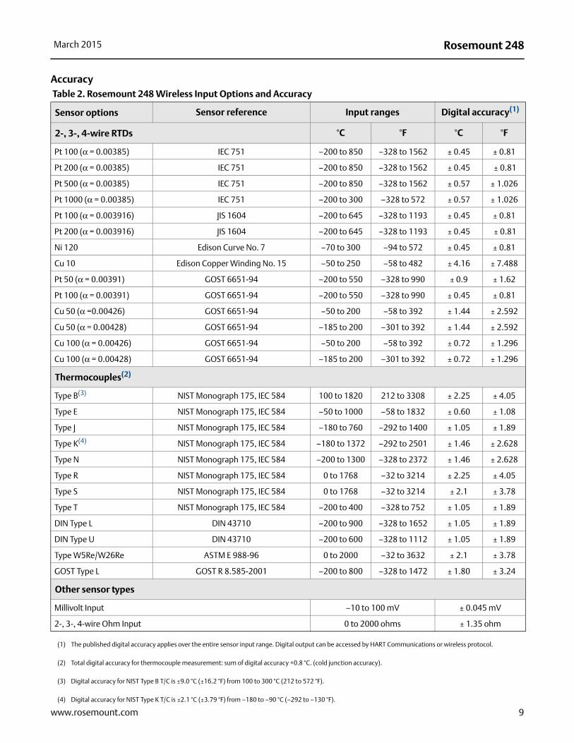
Accuracy Table 2. Rosemount 248 Wireless Input Options and Accuracy
Sensor options Sensor reference Input ranges Digital accuracy(1)
2-, 3-, 4-wire RTDs °C °F °C °F
Pt 100 (α = 0.00385) IEC 751 –200 to 850 –328 to 1562 ± 0.45 ± 0.81
Pt 200 (α = 0.00385) IEC 751 –200 to 850 –328 to 1562 ± 0.45 ± 0.81
Pt 500 (α = 0.00385) IEC 751 –200 to 850 –328 to 1562 ± 0.57 ± 1.026
Pt 1000 (α = 0.00385) IEC 751 –200 to 300 –328 to 572 ± 0.57 ± 1.026
Pt 100 (α = 0.003916) JIS 1604 –200 to 645 –328 to 1193 ± 0.45 ± 0.81
Pt 200 (α = 0.003916) JIS 1604 –200 to 645 –328 to 1193 ± 0.45 ± 0.81
Ni 120 Edison Curve No. 7 –70 to 300 –94 to 572 ± 0.45 ± 0.81
Cu 10 Edison Copper Winding No. 15 –50 to 250 –58 to 482 ± 4.16 ± 7.488
Pt 50 (α = 0.00391) GOST 6651-94 –200 to 550 –328 to 990 ± 0.9 ± 1.62
Pt 100 (α = 0.00391) GOST 6651-94 –200 to 550 –328 to 990 ± 0.45 ± 0.81
Cu 50 (α =0.00426) GOST 6651-94 –50 to 200 –58 to 392 ± 1.44 ± 2.592
Cu 50 (α = 0.00428) GOST 6651-94 –185 to 200 –301 to 392 ± 1.44 ± 2.592
Cu 100 (α = 0.00426) GOST 6651-94 –50 to 200 –58 to 392 ± 0.72 ± 1.296
Cu 100 (α = 0.00428) GOST 6651-94 –185 to 200 –301 to 392 ± 0.72 ± 1.296
Thermocouples(2)
Type B(3) NIST Monograph 175, IEC 584 100 to 1820 212 to 3308 ± 2.25 ± 4.05
Type E NIST Monograph 175, IEC 584 –50 to 1000 –58 to 1832 ± 0.60 ± 1.08
Type J NIST Monograph 175, IEC 584 –180 to 760 –292 to 1400 ± 1.05 ± 1.89
Type K(4) NIST Monograph 175, IEC 584 –180 to 1372 –292 to 2501 ± 1.46 ± 2.628
Type N NIST Monograph 175, IEC 584 –200 to 1300 –328 to 2372 ± 1.46 ± 2.628
Type R NIST Monograph 175, IEC 584 0 to 1768 –32 to 3214 ± 2.25 ± 4.05
Type S NIST Monograph 175, IEC 584 0 to 1768 –32 to 3214 ± 2.1 ± 3.78
Type T NIST Monograph 175, IEC 584 –200 to 400 –328 to 752 ± 1.05 ± 1.89
DIN Type L DIN 43710 –200 to 900 –328 to 1652 ± 1.05 ± 1.89
DIN Type U DIN 43710 –200 to 600 –328 to 1112 ± 1.05 ± 1.89
Type W5Re/W26Re ASTM E 988-96 0 to 2000 –32 to 3632 ± 2.1 ± 3.78
GOST Type L GOST R 8.585-2001 –200 to 800 –328 to 1472 ± 1.80 ± 3.24
Other sensor types
Millivolt Input –10 to 100 mV ± 0.045 mV
2-, 3-, 4-wire Ohm Input 0 to 2000 ohms ± 1.35 ohm
(1) The published digital accuracy applies over the entire sensor input range. Digital output can be accessed by HART Communications or wireless protocol.
(2) Total digital accuracy for thermocouple measurement: sum of digital accuracy +0.8 °C. (cold junction accuracy).
(3) Digital accuracy for NIST Type B T/C is ±9.0 °C (±16.2 °F) from 100 to 300 °C (212 to 572 °F).
(4) Digital accuracy for NIST Type K T/C is ±2.1 °C (±3.79 °F) from –180 to –90 °C (–292 to –130 °F).

Rosemount 248 March 2015
Ambient Temperature Effect Table 3. Rosemount 248 Wireless Ambient Temperature Effect
Sensor options Sensor referenceInput range
(°C)Temperature effects per 1.0 °C (1.8 °F) change in ambient temperature(1)(2) Range
2-, 3-, 4-wire RTDs
Pt 100(α = 0.00385)
IEC 751 –200 to 850 0.009 °C (0.0162 °F)Entire Sensor Input
Range
Pt 200(α = 0.00385)
IEC 751 –200 to 850 0.012 °C (0.0216 °F)Entire Sensor Input
Range
Pt 500(α = 0.00385)
IEC 751 –200 to 850 0.009 °C (0.0162 °F)Entire Sensor Input
Range
Pt 1000(α = 0.00385)
IEC 751 –200 to 300 0.009 °C (0.0162 °F)Entire Sensor Input
Range
Pt 100(α = 0.003916)
JIS 1604 –200 to 645 0.009 °C (0.0162 °F)Entire Sensor Input
Range
Pt 200(α = 0.003916)
JIS 1604 –200 to 645 0.012 °C (0.0216 °F)Entire Sensor Input
Range
Ni 120 Edison Curve No. 7 –70 to 300 0.009 °C (0.0162 °F)Entire Sensor Input
Range
Cu 10Edison Copper
Winding No. 15–50 to 250 0.06 °C (0.162 °F)
Entire Sensor Input Range
Pt 50(α = 0.003910)
GOST 6651-94 –200 to 550 0.018 °C (0.0324 °F)Entire Sensor Input
Range
Pt 100(α = 0.003910)
GOST 6651-94 –200 to 550 0.009 °C (0.0162 °F)Entire Sensor Input
Range
Cu 50(α = 0.00426)
GOST 6651-94 –50 to 200 0.012 °C (0.0216 °F)Entire Sensor Input
Range
Cu 50(α = 0.00428)
GOST 6651-94 –185 to 200 0.012 °C (0.0216 °F)Entire Sensor Input
Range
Cu 100(α = 0.00426)
GOST 6651-94 –50 to 200 0.009 °C (0.0162 °F)Entire Sensor Input
Range
Cu 100(α = 0.00428)
GOST 6651-94 –185 to 200 0.009 °C (0.0162 °F)Entire Sensor Input
Range
Thermocouples
Type BNIST Monograph 175,
IEC 584100 to 1820
0.0435 °C T ≥ 1000 °C
0.096 °C - (0.0075% of (T - 300)) 300 °C ≤ T < 1000 °C
0.162 °C - (0.033% of (T - 100)) 100 °C ≤ T < 300 °C
Type ENIST Monograph 175,
IEC 584–50 to 1000 0.015 °C + (0.00129% of absolute value T) All
Type JNIST Monograph 175,
IEC 584–180 to 760
0.0162 °C + (0.00087% of T) T ≥ 0 °C
0.0162 °C + (0.0075% of absolute value T) T < 0 °C
Type KNIST Monograph 175,
IEC 584–180 to 1372
0.0183 °C + (0.0027% of T) T ≥ 0 °C
0.0183 °C + (0.0075% of absolute value T) T < 0 °C
10 www.rosemount.com

Rosemount 248March 2015
Transmitters can be installed in locations where the ambient temperature is between –40 and 85 °C (–40 and 185 °F). In order to maintain excellent accuracy performance, each transmitter is individually characterized over this ambient temperature range at the factory.
Temperature effects example
When using a Pt 100 (α = 0.00385) sensor input at 30 °C ambient temperature:
Digital Temperature Effects: 0.009 °C x (30 - 20) = 0.09 °C
Worst Case Error: Digital + Digital Temperature Effects = 0.45 °C + 0.09 °C = 0.54 °C
Total Probable Error: °C
Thermocouples
Type NNIST Monograph 175,
IEC 584–200 to 1300 0.0204 °C + (0.00108% of absolute value T) All
Type RNIST Monograph 175,
IEC 5840 to 1768
0.048 °C T ≥ 200 °C
0.069 °C - (0.0108% of T) T < 200 °C
Type SNIST Monograph 175,
IEC 5840 to 1768
0.048 °C T ≥ 200 °C
0.069 °C - (0.0108% of T) T < 200 °C
Type TNIST Monograph 175,
IEC 584–200 to 400
0.0192 °C T ≥ 0 °C
0.0192 °C + (0.0129% of absolute value T) T < 0 °C
DIN Type L DIN 43710 –200 to 9000.0162 °C + (0.00087% of T) T ≥ 0 °C
0.0162 °C + (0.0075% of absolute value T) T < 0 °C
DIN Type U DIN 43710 –200 to 9000.0192 °C T ≥ 0 °C
0.0192 °C + (0.0129% of absolute value T) T < 0 °C
Type W5Re/W26Re ASTM E 988-96 0 to 20000.048 °C T ≥ 200 °C
0.069 °C - (0.0108% of T) T < 200 °C
GOST Type L GOST R 8.585-2001 –200 to 8000.021 °C T ≥ 0 °C
0.0105 °C + (0.0045% of absolute value T) T < 0 °C
Other sensor types
Millivolt Input –10 to 100 mV 0.0015 mVEntire Sensor Input
Range
2-, 3-, 4-wire Ohm 0 to 2000 W 0.0252 WEntire Sensor Input
Range
(1) Change in ambient is with reference to the calibration temperature of the transmitter 68 °F (20 °C) from factory.
(2) Ambient temperature effect specification valid over minimum temperature span of 28 °C (50 °F).
Table 3. Rosemount 248 Wireless Ambient Temperature Effect
0.452 0.092+ 0.459=
11www.rosemount.com

Rosemount 248 March 2015
Product Certifications
European Directive Information
A copy of the EC Declaration of Conformity can be found at the end of the Quick Start Guide. The most recent revision of the EC Declaration of Conformity can be found at www.rosemount.com.
Ordinary Location Certification
As standard, the transmitter has been examined and tested to determine that the design meets the basic electrical, mechanical, and fire protection requirements by a nationally recognized test laboratory (NRTL) as accredited by the Federal Occupational Safety and Health Administration (OSHA).
Telecommunication Compliance
All wireless devices require certification to ensure that they adhere to regulations regarding the use of the RF spectrum. Nearly every country requires this type of product certification. Emerson is working with governmental agencies around the world to supply fully compliant products and remove the risk of violating country directives or laws governing wireless device usage.
FCC and IC
This device complies with Part 15 of the FCC Rules. Operation is subject to the following conditions: This devices may not cause harmful interference, this devices must accept any interference received, including interference that may cause undesired operation. This device must be installed to ensure a minimum antenna separation distance of 20 cm from all persons.
Installing Equipment in North America
The US National Electrical Code (NEC) and the Canadian Electrical Code (CEC) permit the use of Division marked equipment in Zones and Zone marked equipment in Divisions. The markings must be suitable for the area classification, gas, and temperature class. This information is clearly defined in the respective codes.
USA
I5 USA Intrinsically SafeCertificate: 70008071 (Polymer housing)Standards: FM 3600: 2011; FM 3610: 2010;
FM 3611: 2004; UL 61010-1: 2012; UL 50E: 2012; ANSI/IEC 60529:2004
Markings: Intrinsically Safe: CL I, DIV 1, GP A, B, C, D; CL I, DIV 2, GP A, B, C, D; Class I, Zone 0, AEx ia IIC T4/T5 Ga; T4(-50 °C ≤ Ta ≤ +70 °C); T5(-50 °C ≤ Ta ≤ +40 °C); when installed per Rosemount drawing 00249-2020; TYPE 4X, IP66/67See Table 4 at the end of the Product Certifications section for Entity Parameters.
Special Condition for Safe Use (X):
1. Battery Exchange: The battery module can be change inside hazardous gas-explosive locations. During battery change it must be assured that the connections are free from dust or dirt.
I5 USA Intrinsically SafeCertificate: 3039717 (Aluminum housing)Standards: FM Class 3600:1998, FM Class 3610:2010,
FM Class 3611:2004, FM Class 3810:2005, ANSI/NEMA 250:2003;ANSI/IEC 60529:2004
Markings: IS CL I/II/III, DIV 1, GP A, B, C, D, E, F, G;IS CL I, Zone 0, AEx ia IIC; NI CL I, DIV 2,GP A, B, C, D; T4(-50 °C ≤ Ta ≤ +70 °C),T5(-50 °C ≤ Ta ≤ +40 °C) when installed perRosemount drawing 00249-1000; Type 4X;IP66/67See Table 4 at the end of the Product Certifications section for Entity Parameters.
N5 USA Nonincendive and Dust-IgnitionproofCertificate: 3039717 (Aluminum housing)Standards: FM Class 3600:1998, FM Class 3611:2004,
FM Class 3810:2005, ANSI/NEMA 250: 2003; ANSI/IEC 60529: 2004
Markings: NI CL I, DIV 2, GP A, B, C, D; T4(-50 °C ≤ Ta ≤ +70 °C); DIP CL II/III, DIV 1, GP E, F, G; -50 °C ≤ Ta ≤ +85 °C; when installed per Rosemount drawing 00249-1000; Type 4X; IP66/67
12 www.rosemount.com
Rosemount 248March 2015
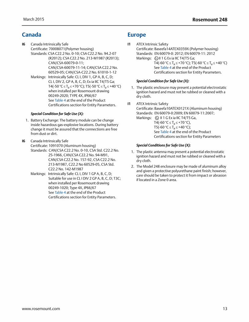
Canada
I6 Canada Intrinsically SafeCertificate: 70008071(Polymer housing)Standards: CSA C22.2 No. 0-10; CSA C22.2 No. 94.2-07
(R2012); CSA C22.2 No. 213-M1987 (R2013); CAN/CSA-60079-0-11; CAN/CSA-60079-11-14; CAN/CSA C22.2 No. 60529-05; CAN/CSA-C22.2 No. 61010-1-12
Markings: Intrinsically Safe: CL I, DIV 1, GP A, B, C, D; CL I, DIV 2, GP A, B, C, D; Ex ia IIC T4/T5 Ga; T4(-50 °C ≤ Ta ≤ +70 °C); T5(-50 °C ≤ Ta ≤ +40 °C) when installed per Rosemount drawing 00249-2020; TYPE 4X, IP66/67See Table 4 at the end of the Product Certifications section for Entity Parameters.
Special Condition for Safe Use (X):
1. Battery Exchange: The battery module can be change inside hazardous gas-explosive locations. During battery change it must be assured that the connections are free from dust or dirt.
I6 Canada Intrinsically SafeCertificate: 1091070 (Aluminum housing)Standards: CAN/CSA C22.2 No. 0-10, CSA Std. C22.2 No.
25-1966, CAN/CSA C22.2 No. 94-M91, CAN/CSA C22.2 No. 157-92, CSA C22.2 No. 213-M1987, C22.2 No 60529-05, CSA Std. C22.2 No. 142-M1987
Markings: Intrinsically Safe: CL I, DIV 1 GP A, B, C, D; Suitable for use in CL I DIV 2 GP A, B, C, D; T3C; when installed per Rosemount drawing 00249-1020; Type 4X, IP66/67See Table 4 at the end of the Product Certifications section for Entity Parameters.
Europe
I1 ATEX Intrinsic SafetyCertificate: Baseefa14ATEX0359X (Polymer housing)Standards: EN 60079-0: 2012; EN 60079-11: 2012Markings: II 1 G Ex ia IIC T4/T5 Ga;
T4(-60 °C ≤ Ta ≤ +70 °C); T5(-60 °C ≤ Ta ≤ +40 °C)See Table 4 at the end of the Product Certifications section for Entity Parameters.
Special Condition for Safe Use (X):
1. The plastic enclosure may present a potential electrostatic ignition hazard and must not be rubbed or cleaned with a dry cloth.
I1 ATEX Intrinsic SafetyCertificate: Baseefa10ATEX0121X (Aluminum housing)Standards: EN 60079-0:2009; EN 60079-11:2007;Markings: II 1 G Ex ia IIC T4/T5 Ga,
T4(-60 °C ≤ Ta ≤ +70 °C), T5(-60 °C ≤ Ta ≤ +40 °C);See Table 4 at the end of the Product Certifications section for Entity Parameters
Special Conditions for Safe Use (X):
1. The plastic antenna may present a potential electrostatic ignition hazard and must not be rubbed or cleaned with a dry cloth.
2. The Model 248 enclosure may be made of aluminum alloy and given a protective polyurethane paint finish; however, care should be taken to protect it from impact or abrasion if located in a Zone 0 area.
13www.rosemount.com

Rosemount 248 March 2015
International
I7 IECEx Intrinsic SafetyCertificate: IECEx BAS 14.0158X (Polymer housing)Standards: IEC 60079-0: 2011; IEC 60079-11: 2011Markings: Ex ia IIC T4/T5 Ga, T4(-60 °C ≤ Ta ≤ +70 °C),
T5(-60 °C ≤ Ta ≤ +40 °C);See Table 4 at the end of the Product Certifications section for Entity Parameters.
Special Condition for Safe Use (X):
1. The plastic enclosure may present a potential electrostatic ignition hazard and must not be rubbed or cleaned with a dry cloth.
I7 IECEx Intrinsic SafetyCertificate: IECEx BAS 10.0059X (Aluminum housing)Standards: IEC 60079-0:2011, IEC 60079-11:2011;Markings: Ex ia IIC T4/T5 Ga, T4(-60 °C ≤ Ta ≤ +70 °C),
T5(-60 °C ≤ Ta ≤ +40 °C); See Table 4 at the end of the Product Certifications section for Entity Parameters.
Special Conditions for Safe Use (X):
1. The surface resistivity of the antenna is greater than 1GΩ. To avoid electrostatic charge build-up, it must not be rubbed or cleaned with solvents or a dry cloth.
2. The Model 701PBKKF Power Module and Intelligent Power Module 71008 may be replaced in a hazardous area. The Power Modules have a surface resistivity greater than 1GΩ and must be properly installed in the wireless device enclosure. Care must be taken during transportation to and from the point of installation to prevent electrostatic charge build-up.
3. The Model 248 enclosure may be made of aluminum alloy and given a protective polyurethane paint finish; however, care should be taken to protect it from impact or abrasion if located in a Zone 0 area.
EAC - Belarus, Kazakhstan, Russia
IM Technical Regulations Custom Union (EAC) Intrinsic SafetyCertificate: RU C-US.Gb05.B.00289 (Aluminum housing)Markings: 0Ex ia IIC T4 Ga X (-60 °C ≤ Ta ≤ +70 °C);
0Ex ia IIC T5 Ga X (-60 °C ≤ Ta ≤ +40 °C);
Tables
Table 4. Entity Parameters
USA, ATEX, IECEx & Canada (Polymer)
Canada (Aluminum)
Voltage Uo 6.6 V 6.6 V
Current Io 26.2 mA 26.2 mA
Power Po 42.6 mW 42.6 mW
Capacitance Co 11 μF 23.8 μF
Inductance Lo 25 mH 25 mH
14 www.rosemount.com

Rosemount 248March 2015
Dimensional Drawings
Figure 4. Rosemount 248 Wireless Remote Mount (Polymer Housing)
Dimensions are in inches (millimeters).
Figure 5. Rosemount 248 Wireless Direct Mount (Polymer Housing)
Dimensions are in inches (millimeters).
4.24 (107,6)
5.75(146,1)
5.05(128,4)
4.57(116,0)
4.24 (107,6)
4.57(116,0)
5.75(146,1)
15www.rosemount.com

Rosemount 248 March 2015
Figure 6. Rosemount 248 Wireless Remote Mount (Aluminum Housing)
Remote mounted temperature sensor specified separately.Dimensions are in inches (millimeters).
Figure 7. Rosemount 248 Wireless Direct Mount (Aluminum Housing)
Direct mounted temperature sensor specified separately (see ordering option code XA).Dimensions are in inches (millimeters).
7.94(201,6)
4.46(113,2)
3.51(89,2)
5.71(145)
3.99(101,3)
90°
7.81(198,4)
6.05(153,7)
4.26(108,2)
7.94 (201,6)
90°
4.35(110,6)
7.81(198,4)
4.26(108,2)
6.05(153,7)
16 www.rosemount.com

Rosemount 248March 2015
17www.rosemount.com

Rosemount 24800813-0100-4248, Rev DA
Product Data SheetMarch 2015
Rosemount World HeadquartersEmerson Process Management 6021 Innovation BlvdShakopee, MN 55379, USA
+1 800 999 9307 or +1 952 906 8888+1 952 949 7001 [email protected]
North America Regional OfficeEmerson Process Management 8200 Market Blvd.Chanhassen, MN 55317, USA
+1 800 999 9307 or +1 952 906 8888+1 952 949 7001 [email protected]
Latin America Regional OfficeEmerson Process Management 1300 Concord Terrace, Suite 400Sunrise, Florida, 33323, USA
+1 954 846 5030+1 954 846 [email protected]
Europe Regional OfficeEmerson Process Management Europe GmbHNeuhofstrasse 19a P.O. Box 1046CH 6340 BaarSwitzerland
+41 (0) 41 768 6111+41 (0) 41 768 6300 [email protected]
Asia Pacific Regional OfficeEmerson Process Management Asia Pacific Pte Ltd1 Pandan CrescentSingapore 128461
+65 6777 8211+65 6777 0947 [email protected]
Middle East and Africa Regional OfficeEmerson Process Management Emerson FZE P.O. Box 17033,Jebel Ali Free Zone - South 2Dubai, United Arab Emirates
+971 4 8118100+971 4 8865465 [email protected]
Standard Terms and Conditions of Sale can be found at: www.rosemount.com\terms_of_sale.The Emerson logo is a trademark and service mark of Emerson Electric Co.Rosemount and Rosemount logotype are registered trademarks of Rosemount Inc.SmartPower is a trademark of Rosemount Inc.PlantWeb is a registered trademark of one of the Emerson Process Management group of companies.HART and WirelessHART are registered trademarks of FieldComm Group.All other marks are the property of their respective owners.© 2015 Rosemount Inc. All rights reserved.