September 2014 Rosemount DP Flow Rosemount 485 ... Rosemount...133 September 2014 Rosemount DP Flow...
15
133 Rosemount DP Flow September 2014 www.rosemount.com Rosemount 485 Annubar ® Primary Element Rosemount 485 Annubar Primary Element utilizes a T-shaped sensor design that offers best in class accuracy and performance. Up to 0.75% Flow Rate Accuracy Lowest permanent pressure loss of any DP Flowmeter Available in 2 to 96-in. (50 - 2400 mm) line sizes Additional Information Specifications: page 138 Dimensional Drawings: page 207 Installation and Flowmeter Orientation: page 181 Ordering information Table 1. Rosemount 485 Annubar Primary Ordering Information H The Standard offering represents the most common options. The starred options (H) should be selected for best delivery. __The Expanded offering is subject to additional delivery lead time. Model DP Flow primary type 485 Annubar Primary Element Fluid type L Liquid H G Gas H S Steam H Line size 020 2-in. (50 mm) H 025 2 1 /2-in. (63.5 mm) H 030 3-in. (80 mm) H 035 3 1 /2-in. (89 mm) H 040 4-in. (100 mm) H 050 5-in. (125 mm) H 060 6-in. (150 mm) H 070 7-in. (175 mm) H 080 8-in. (200 mm) H 100 10-in. (250 mm) H 120 12-in. (300 mm) H 140 14-in. (350 mm) 160 16-in. (400 mm) 180 18-in. (450 mm) 200 20-in. (500 mm) 240 24-in. (600 mm) 300 30-in. (750 mm) 360 36-in. (900 mm) 420 42-in. (1066 mm) 480 48-in. (1210 mm) 600 60-in. (1520 mm) 720 72-in. (1820 mm)
Transcript of September 2014 Rosemount DP Flow Rosemount 485 ... Rosemount...133 September 2014 Rosemount DP Flow...
133
Rosemount DP FlowSeptember 2014
www.rosemount.com
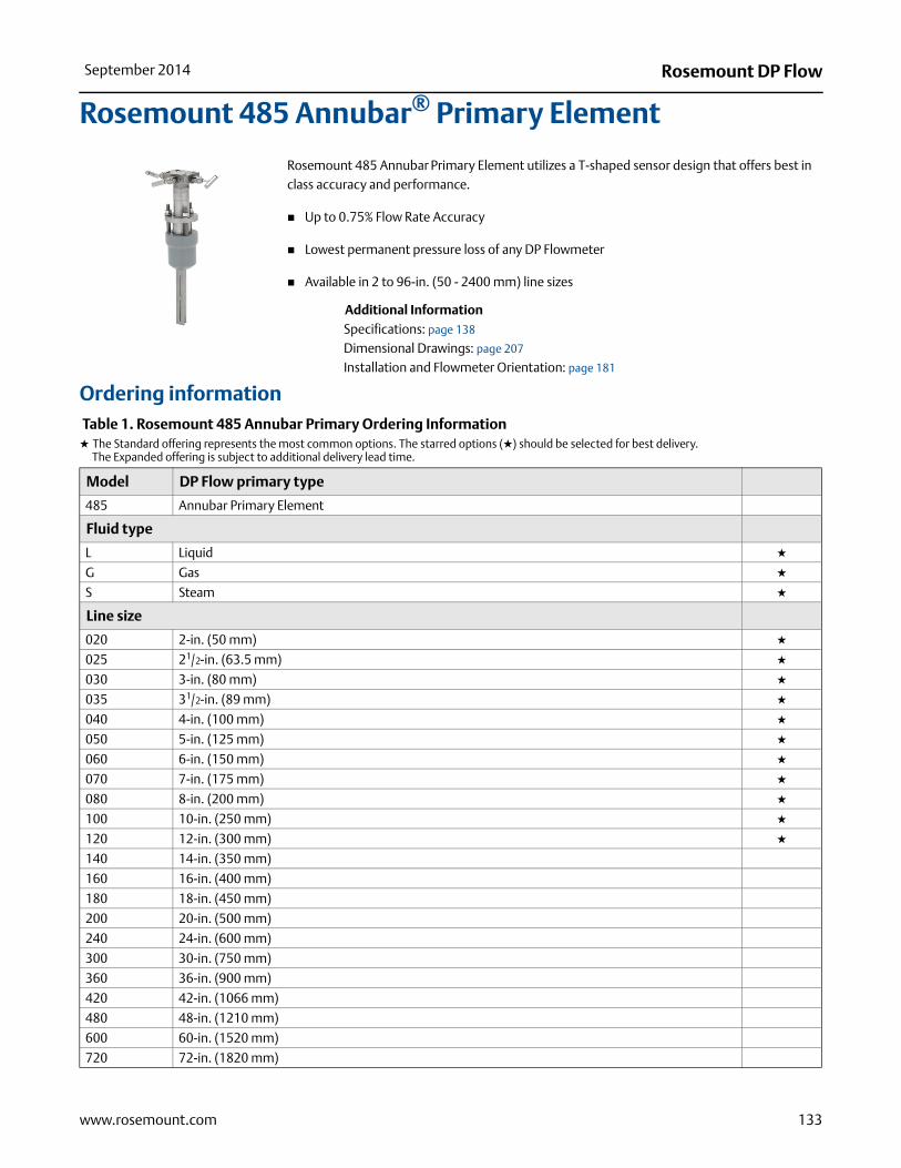
Rosemount 485 Annubar® Primary Element
Rosemount 485 Annubar Primary Element utilizes a T-shaped sensor design that offers best in class accuracy and performance.
Up to 0.75% Flow Rate Accuracy
Lowest permanent pressure loss of any DP Flowmeter
Available in 2 to 96-in. (50 - 2400 mm) line sizes
Additional InformationSpecifications: page 138
Dimensional Drawings: page 207
Installation and Flowmeter Orientation: page 181
Ordering information Table 1. Rosemount 485 Annubar Primary Ordering InformationH The Standard offering represents the most common options. The starred options (H) should be selected for best delivery.__The Expanded offering is subject to additional delivery lead time.
Model DP Flow primary type
485 Annubar Primary Element
Fluid type
L Liquid H
G Gas H
S Steam H
Line size
020 2-in. (50 mm) H
025 21/2-in. (63.5 mm) H
030 3-in. (80 mm) H
035 31/2-in. (89 mm) H
040 4-in. (100 mm) H
050 5-in. (125 mm) H
060 6-in. (150 mm) H
070 7-in. (175 mm) H
080 8-in. (200 mm) H
100 10-in. (250 mm) H
120 12-in. (300 mm) H
140 14-in. (350 mm)
160 16-in. (400 mm)
180 18-in. (450 mm)
200 20-in. (500 mm)
240 24-in. (600 mm)
300 30-in. (750 mm)
360 36-in. (900 mm)
420 42-in. (1066 mm)
480 48-in. (1210 mm)
600 60-in. (1520 mm)
720 72-in. (1820 mm)
134
Rosemount DP Flow September 2014
www.rosemount.com
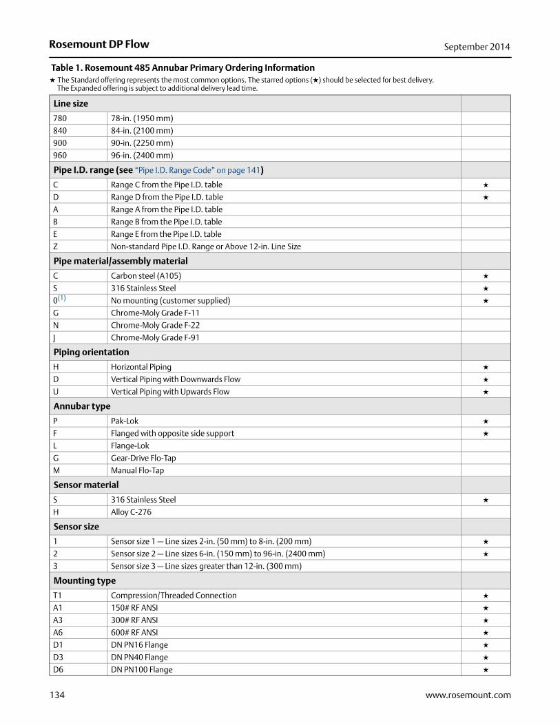
Line size
780 78-in. (1950 mm)
840 84-in. (2100 mm)
900 90-in. (2250 mm)
960 96-in. (2400 mm)
Pipe I.D. range (see “Pipe I.D. Range Code” on page 141)
C Range C from the Pipe I.D. table H
D Range D from the Pipe I.D. table H
A Range A from the Pipe I.D. table
B Range B from the Pipe I.D. table
E Range E from the Pipe I.D. table
Z Non-standard Pipe I.D. Range or Above 12-in. Line Size
Pipe material/assembly material
C Carbon steel (A105) H
S 316 Stainless Steel H
0(1) No mounting (customer supplied) H
G Chrome-Moly Grade F-11
N Chrome-Moly Grade F-22
J Chrome-Moly Grade F-91
Piping orientation
H Horizontal Piping H
D Vertical Piping with Downwards Flow H
U Vertical Piping with Upwards Flow H
Annubar type
P Pak-Lok H
F Flanged with opposite side support H
L Flange-Lok
G Gear-Drive Flo-Tap
M Manual Flo-Tap
Sensor material
S 316 Stainless Steel H
H Alloy C-276
Sensor size
1 Sensor size 1 — Line sizes 2-in. (50 mm) to 8-in. (200 mm) H
2 Sensor size 2 — Line sizes 6-in. (150 mm) to 96-in. (2400 mm) H
3 Sensor size 3 — Line sizes greater than 12-in. (300 mm)
Mounting type
T1 Compression/Threaded Connection H
A1 150# RF ANSI H
A3 300# RF ANSI H
A6 600# RF ANSI H
D1 DN PN16 Flange H
D3 DN PN40 Flange H
D6 DN PN100 Flange H
Table 1. Rosemount 485 Annubar Primary Ordering InformationH The Standard offering represents the most common options. The starred options (H) should be selected for best delivery.__The Expanded offering is subject to additional delivery lead time.
135
Rosemount DP FlowSeptember 2014
www.rosemount.com
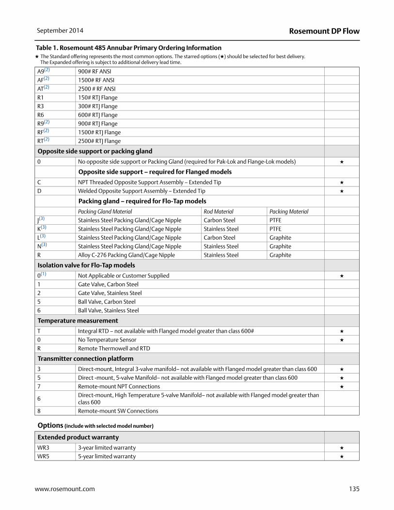
A9(2) 900# RF ANSI
AF(2) 1500# RF ANSI
AT(2) 2500 # RF ANSI
R1 150# RTJ Flange
R3 300# RTJ Flange
R6 600# RTJ Flange
R9(2) 900# RTJ Flange
RF(2) 1500# RTJ Flange
RT(2) 2500# RTJ Flange
Opposite side support or packing gland
0 No opposite side support or Packing Gland (required for Pak-Lok and Flange-Lok models) H
Opposite side support – required for Flanged models
C NPT Threaded Opposite Support Assembly – Extended Tip H
D Welded Opposite Support Assembly – Extended Tip H
Packing gland – required for Flo-Tap models
Packing Gland Material Rod Material Packing Material
J(3) Stainless Steel Packing Gland/Cage Nipple Carbon Steel PTFE
K(3) Stainless Steel Packing Gland/Cage Nipple Stainless Steel PTFE
L(3) Stainless Steel Packing Gland/Cage Nipple Carbon Steel Graphite
N(3) Stainless Steel Packing Gland/Cage Nipple Stainless Steel Graphite
R Alloy C-276 Packing Gland/Cage Nipple Stainless Steel Graphite
Isolation valve for Flo-Tap models
0(1) Not Applicable or Customer Supplied H
1 Gate Valve, Carbon Steel
2 Gate Valve, Stainless Steel
5 Ball Valve, Carbon Steel
6 Ball Valve, Stainless Steel
Temperature measurement
T Integral RTD – not available with Flanged model greater than class 600# H
0 No Temperature Sensor H
R Remote Thermowell and RTD
Transmitter connection platform
3 Direct-mount, Integral 3-valve manifold– not available with Flanged model greater than class 600 H
5 Direct -mount, 5-valve Manifold– not available with Flanged model greater than class 600 H
7 Remote-mount NPT Connections H
6Direct-mount, High Temperature 5-valve Manifold– not available with Flanged model greater than class 600
8 Remote-mount SW Connections
Options (include with selected model number)
Extended product warranty
WR3 3-year limited warranty H
WR5 5-year limited warranty H
Table 1. Rosemount 485 Annubar Primary Ordering InformationH The Standard offering represents the most common options. The starred options (H) should be selected for best delivery.__The Expanded offering is subject to additional delivery lead time.

136
Rosemount DP Flow September 2014
www.rosemount.com
Pressure testing
P1(4) Hydrostatic Testing with Certificate
PX(4) Extended Hydrostatic Testing
Special cleaning
P2 Cleaning for Special Services
PA Cleaning per ASTM G93 level D (section 11.4)
Material testing
V1 Dye Penetrant Exam
Material examination
V2 Radiographic Examination
Flow calibration
W1 Flow Calibration (Average K)
WZ Special Calibration
Special inspection
QC1 Visual & Dimensional Inspection with Certificate H
QC7 Inspection & Performance Certificate H
Surface finish
RL Surface finish for Low Pipe Reynolds Number in Gas & Steam H
RH Surface finish for High Pipe Reynolds Number in Liquid H
Material traceability certification
Q8(5) Material Traceability Certificate per EN 10204:2004 3.1 H
Code conformance
J2(6) ANSI/ASME B31.1
J3(6) ANSI/ASME B31.3
Materials conformance
J5(7) NACE MR-0175 / ISO 15156
Country certification
J6 European Pressure Directive (PED) H
J1 Canadian Registration
Installed in flanged pipe spool section
H3 150# Flanged Connection with Rosemount Standard Length and Schedule
H4 300# Flanged Connection with Rosemount Standard Length and Schedule
H5 600# Flanged Connection with Rosemount Standard Length and Schedule
Instrument connections for remote mount option
G2 Needle Valves, Stainless Steel H
G6 OS&Y Gate Valve, Stainless Steel H
G1 Needle Valves, Carbon Steel
G3 Needle Valves, Alloy C-276
G5 OS&Y Gate Valve, Carbon Steel
G7 OS&Y Gate Valve, Alloy C-276
Table 1. Rosemount 485 Annubar Primary Ordering InformationH The Standard offering represents the most common options. The starred options (H) should be selected for best delivery.__The Expanded offering is subject to additional delivery lead time.

137
Rosemount DP FlowSeptember 2014
www.rosemount.com
Special shipment
Y1 Mounting Hardware Shipped Separately H
Attach to
H1 Attach to Transmitter
Special dimensions
VM Variable Mounting
VT Variable Tip
VS Variable length Spool Section
V9 Special Dimension
Typical model number: 485 L 060 D C H P S 2 T1 0 0 0 3
(1) Provide the “A” dimension for Flanged (page 209), Flange-Lok (page 208), and Threaded Flo-Tap models (page 211). Provide the “B” dimension for Flange Flo-Tap models (page 210).
(2) Available in remote mount applications only.
(3) The cage nipple is constructed of 304SST.
(4) Applies to flow element only, mounting hardware not tested.
(5) Instrument Connections for Remote Mount Options and Isolation Valves for Flo-tap Models are not included in the Material Traceability Certification.
(6) Not available with Transmitter Connection Platform 6.
(7) Materials of Construction comply with metallurgical requirements within NACE MR0175/ISO 15156 for sour oil field production environments. Environmental limits apply to certain materials. Consult latest standard for details. Selected materials also conform to NACE MR0103 for sour refining environments.
Table 1. Rosemount 485 Annubar Primary Ordering InformationH The Standard offering represents the most common options. The starred options (H) should be selected for best delivery.__The Expanded offering is subject to additional delivery lead time.

138
Rosemount DP Flow September 2014
www.rosemount.com
Specifications
Performance specifications
Performance statement assumptionsMeasured pipe I.D. (or Measured pipe cross sectional area)
Discharge coefficient factor±0.75% of flow rate
Repeatability±0.1%
Line sizes
Sensor Size 1: 2-in. to 8-in. (50 to 200 mm)
Sensor Size 2: 6-in. to 96-in. (150 to 2400 mm)
Sensor Size 3: 12-in. to 96-in. (300 to 2400 mm)
NoteSome mounting types are not available in larger line sizes.
Table 2. Reynolds Number and Probe Width
Sizing Contact an Emerson Process Management representative for assistance. A Configuration Data Sheet is required prior to order for application verification. To complete the Configuration Data Sheet go to: http://www3.emersonprocess.com/Rosemount/DP_Flow/Application/Pages/PCDefault.aspx
Flow turndown10:1 or better
Annubar sensor surface finishThe front surface of the Annubar primary is textured for high Reynolds number applications (typically gas and steam). The surface texture creates a more turbulent boundary layer on the front surface of the sensor. The increased turbulence produces a more predictable and repeatable separation of flow at the edge of the sensor. The appropriate surface finish will be determined for each application by the Emerson Process Management sizing program, Instrument Toolkit software.
Functional specifications
Service
Liquid
Gas
Steam
Process temperature limits
Direct Mount Transmitter
500 °F (260 °C)
750 °F (398 °C) when used with a direct mount, high temperature 5-valve manifold (Transmitter Connection Platform code 6). Maximum temperature limit for steam processes is 650 °F (343 °C).
400 °F (204 °C) when top mounted in steam service
Remote Mount Transmitter
1250 °F (677 °C) – Alloy C-276 Sensor Material (For superheated steam applications above 1000 °F (538 °C), it is recommended that the Rosemount 585 with Alloy 800H sensor material is used.)
850 °F (454 °C) – Stainless Steel Sensor Material
Sensor size
Minimum rod Reynolds Number (Rd)
Probe width (d) (inches)
1 6500 0.590-in. (14.99 mm)2 12500 1.060-in. (26.92 mm)3 25000 1.935-in. (49.15 mm)
Where
d = Probe width (feet)
v = Velocity of fluid (ft/sec)
p = Density of fluid (lbm/ft3)
= Viscosity of the fluid (lbm/ft-sec)
Rdd v p
---------------------=
Pressure and temperature limits (1)
Direct Mount Transmitter
Up to 600# ANSI (1440 psig at 100 °F (99 bar at 38 °C))
Integral temperature measurement is not available with Flanged mounting type greater than class 600
Remote Mount Transmitter
Up to 2500# ANSI (6000 psig at 100 °F (416 bar at 38 °C)).
(1) Static pressure selection may effect pressure limitations.
139
Rosemount DP FlowSeptember 2014
www.rosemount.com
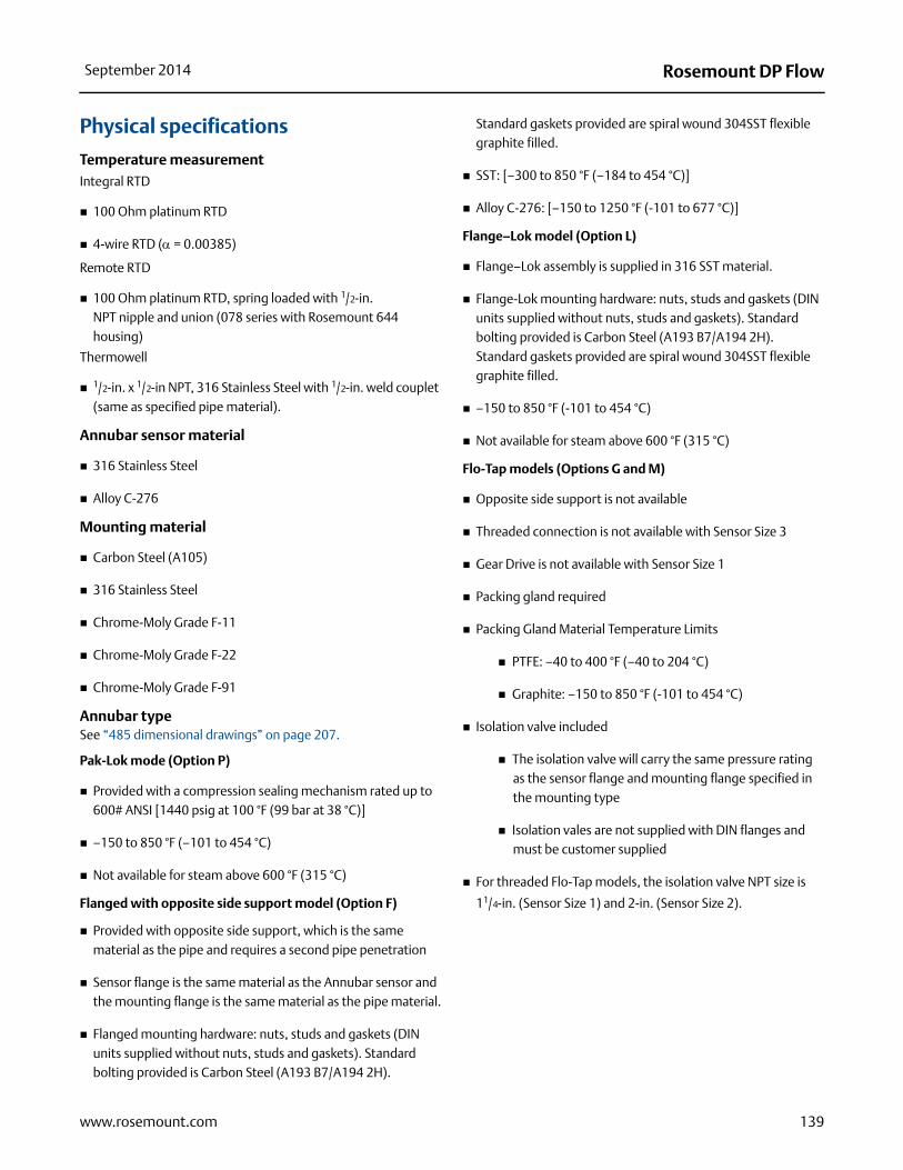
Physical specifications
Temperature measurementIntegral RTD
100 Ohm platinum RTD
4-wire RTD ( = 0.00385)
Remote RTD
100 Ohm platinum RTD, spring loaded with 1/2-in. NPT nipple and union (078 series with Rosemount 644 housing)
Thermowell
1/2-in. x 1/2-in NPT, 316 Stainless Steel with 1/2-in. weld couplet (same as specified pipe material).
Annubar sensor material
316 Stainless Steel
Alloy C-276
Mounting material
Carbon Steel (A105)
316 Stainless Steel
Chrome-Moly Grade F-11
Chrome-Moly Grade F-22
Chrome-Moly Grade F-91
Annubar typeSee “485 dimensional drawings” on page 207.
Pak-Lok mode (Option P)
Provided with a compression sealing mechanism rated up to 600# ANSI [1440 psig at 100 °F (99 bar at 38 °C)]
–150 to 850 °F (–101 to 454 °C)
Not available for steam above 600 °F (315 °C)
Flanged with opposite side support model (Option F)
Provided with opposite side support, which is the same material as the pipe and requires a second pipe penetration
Sensor flange is the same material as the Annubar sensor and the mounting flange is the same material as the pipe material.
Flanged mounting hardware: nuts, studs and gaskets (DIN units supplied without nuts, studs and gaskets). Standard bolting provided is Carbon Steel (A193 B7/A194 2H).
Standard gaskets provided are spiral wound 304SST flexible graphite filled.
SST: [–300 to 850 °F (–184 to 454 °C)]
Alloy C-276: [–150 to 1250 °F (-101 to 677 °C)]
Flange–Lok model (Option L)
Flange–Lok assembly is supplied in 316 SST material.
Flange-Lok mounting hardware: nuts, studs and gaskets (DIN units supplied without nuts, studs and gaskets). Standard bolting provided is Carbon Steel (A193 B7/A194 2H). Standard gaskets provided are spiral wound 304SST flexible graphite filled.
–150 to 850 °F (-101 to 454 °C)
Not available for steam above 600 °F (315 °C)
Flo-Tap models (Options G and M)
Opposite side support is not available
Threaded connection is not available with Sensor Size 3
Gear Drive is not available with Sensor Size 1
Packing gland required
Packing Gland Material Temperature Limits
PTFE: –40 to 400 °F (–40 to 204 °C)
Graphite: –150 to 850 °F (-101 to 454 °C)
Isolation valve included
The isolation valve will carry the same pressure rating as the sensor flange and mounting flange specified in the mounting type
Isolation vales are not supplied with DIN flanges and must be customer supplied
For threaded Flo-Tap models, the isolation valve NPT size is
11/4-in. (Sensor Size 1) and 2-in. (Sensor Size 2).

140
Rosemount DP Flow September 2014
www.rosemount.com
Annubar type specification chart
RTD temperature limitsIntegral and Remote Mounted Thermowell:-100 to 900 °F (-73 to 482 °C)
Instrument connections temperature ranges
Flowmeter installed in flanged pipe spool section (Option Codes H3, H4, and H5)
All pipe spool sections are flanged pipe sections.
The flanged pipe spool section is constructed from the same material as the Pipe Material/Mounting Assembly Material.
Consult the factory for remote temperature measurement and ANSI ratings above 600# and DIN flanges.
Available in carbon steel (A105) and 316 stainless steel
Option code Description Pa
k-Lo
k(1)
(1) Available up to 600# ANSI (1440 psig at 100 °F (99 bar at 38 °C)) rating.
Flan
ge-
Lok
Flan
ge
Man
ual a
nd
gea
r d
rive
Flo-
Tap
T1(1) Pak-Lok Body X
Threaded connection X
A1 150# RF ANSI X X X
A3 300# RF ANSI X X X
A6 600# RF ANSI X X X
A9(2)
(2) Remote mount only.
900# RF ANSI X
AF(2) 1500# RF ANSI X
AT(2) 2500# RF ANSI X
D1 DN PN 16 X X X
D3 DN PN 40 X X X
D6 DN PN 100 X X X
R1 150# RTJ Flange X X X
R3 300# RTJ Flange X X X
R6 600# RTJ Flange X X X
R9(2) 900# RTJ Flange X
RF(2) 1500# RTJ Flange X
RT(2) 2500# RTJ Flange X
Table 3. Minimum/Maximum Temperature Range
Code Description Temperature
G1 Needle Valves, Carbon Steel –20 to 500 °F(–29 to 260 °C)
G2 Needle Valves, Stainless Steel –40 to 600 °F(–40 to 316 °C)
G3 Needle Valves, Alloy C-276 –40 to 600 °F(–40 to 316 °C)
G5 OS&Y Gate Valve, Carbon Steel–20 to 775 °F(–29 to 413 °C)
G6OS&Y Gate Valve, Stainless Steel
–40 to 850 °F(–40 to 454 °C)
G7 OS&Y Gate Valve, Alloy C-276–40 to 1250 °F(–40 to 677 °C)
Table 4. Flanged Pipe Spool Section Schedule
ANSI Schedule
150# ANSI 40300# ANSI 40600# ANSI 80
Table 5. Flange Pipe Spool Section Length
Nominal pipe size Length
2-in. (50 mm) 10.52-in. (267.2 mm)3-in. (80 mm) 11.37-in. (288.8 mm)4-in. (100 mm) 12.74-in. (323.6 mm)6-in. (150 mm) 14.33-in. (364.0 mm)8-in. (200 mm) 16.58-in. (421.1 mm)
141
Rosemount DP FlowSeptember 2014
www.rosemount.com
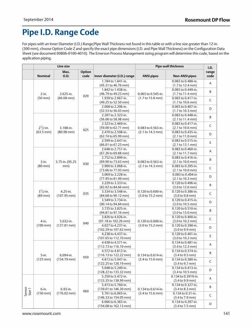
Pipe I.D. Range CodeFor pipes with an Inner Diameter (I.D.) Range/Pipe Wall Thickness not found in this table or with a line size greater than 12-in.(300 mm), choose Option Code Z and specify the exact pipe dimensions (I.D. and Pipe Wall Thickness) on the Configuration Data Sheet (see document 00806-0100-4010). The Emerson Process Management sizing program will determine this code, based on the application piping.
Line size
Inner diameter (I.D.) range
Pipe wall thickness I.D. range codeNominal
Max. O.D.
Option code ANSI pipes Non-ANSI pipes
2-in. (50 mm)
2.625-in. (66.68 mm)
020
1.784 to 1.841-in. (45.31 to 46.76 mm)
0.065 to 0.545-in. (1.7 to 13.8 mm)
0.065 to 0.488-in. (1.7 to 12.4 mm)
A
1.842 to 1.938-in. (46.79 to 49.23 mm)
0.065 to 0.449-in. (1.7 to 11.4 mm)
B
1.939 to 2.067-in. (49.25 to 52.50 mm)
0.065 to 0.417-in. (1.7 to 10.6 mm)
C
2.068 to 2.206-in. (52.53 to 56.03 mm)
0.065 to 0.407-in. (1.7 to 10.3 mm)
D
21/2-in. (63.5 mm)
3.188-in. (80.98 mm)
025
2.207 to 2.322-in. (56.06 to 58.98 mm)
0.083 to 0.563-in. (2.1 to 14.3 mm)
0.083 to 0.448-in. (2.1 to 11.4 mm)
B
2.323 to 2.469-in. (59.00 to 62.71 mm)
0.083 to 0.417-in. (2.1 to 10.6 mm)
C
2.470 to 2.598-in. (62.74 to 65.99 mm)
0.083 to 0.435-in. (2.1 to 11.0 mm)
D
2.599 to 2.647-in. (66.01 to 67.23 mm)
0.083 to 0.515-in. (2.1 to 13.1 mm)
E
3-in. (80 mm)
3.75-in. (95.25 mm)
030
2.648 to 2.751-in. (67.26 to 69.88 mm)
0.083 to 0.563-in. (2.1 to 14.3 mm)
0.083 to 0.460-in. (2.1 to 11.7 mm)
A
2.752 to 2.899-in. (69.90 to 73.63 mm)
0.083 to 0.416-in. (2.1 to 10.6 mm)
B
2.900 to 3.068-in. (73.66 to 77.93 mm)
0.083 to 0.395-in. (2.1 to 10.0 mm)
C
3.069 to 3.228-in.(77.95 to 81.99 mm)
0.083 to 0.404-in (2.1 to 10.3 mm)
D
31/2-in. (89 mm)
4.25-in. (107.95 mm)
035
3.229 to 3.333-in. (82.02 to 84.66 mm)
0.120 to 0.600-in. (3.0 to 15.2 mm)
0.120 to 0.496-in. (3.0 to 12.6 mm)
B
3.334 to 3.548-in. (84.68 to 90.12 mm)
0.120 to 0.386-in. (3.0 to 9.8 mm)
C
3.549 to 3.734-in. (90.14 to 94.84 mm)
0.120 to 0.415-in. (3.0 to 10.5 mm)
D
4-in. (100 mm)
5.032-in. (127.81 mm)
040
3.735 to 3.825-in.(94.87 to 97.16 mm)
0.120 to 0.600-in. (3.0 to 15.2 mm)
0.120 to 0.510-in. (3.0 to 13.0 mm)
B
3.826 to 4.026-in. (97.18 to 102.26 mm)
0.120 to 0.400-in. (3.0 to 10.2 mm)
C
4.027 to 4.237-in. (102.29 to 107.62 mm)
0.120 to 0.390-in. (3.0 to 9.9 mm)
D
4.238 to 4.437-in. (107.65 to 112.70 mm)
0.120 to 0.401-in. (3.0 to 10.2 mm)
E
5-in. (125 mm)
6.094-in. (154.79 mm)
050
4.438 to 4.571-in. (112.73 to 116.10 mm)
0.134 to 0.614-in. (3.4 to 15.6 mm)
0.134 to 0.481-in. (3.4 to 12.2 mm)
A
4.572 to 4.812-in. (116.13 to 122.22 mm)
0.134 to 0.374-in. (3.4 to 9.5 mm)
B
4.813 to 5.047-in. (122.25 to 128.19 mm)
0.134 to 0.380-in. (3.4 to 9.7 mm)
C
5.048 to 5.249-in. (128.22 to 133.32 mm)
0.134 to 0.413-in. (3.4 to 10.5 mm)
D
Sens
or
Size
1 6-in. (150 mm)
6.93-in. (176.02 mm)
060
5.250 to 5.472-in. (133.35 to 138.99 mm)
0.134 to 0.614-in. (3.4 to 15.6 mm)
0.134 to 0.3919-in. (3.4 to 9.9 mm)
A
5.473 to 5.760-in. (139.01 to 146.30 mm)
0.134 to 0.327-in. (3.4 to 8.3 mm)
B
5.761 to 6.065-in. (146.33 to 154.05 mm)
0.134 to 0.31-in. (3.4 to 7.9 mm)
C
6.066 to 6.383-in. (154.08 to 162.13 mm)
0.134 to 0.297-in. (3.4 to 7.5 mm)
D

142
Rosemount DP Flow September 2014
www.rosemount.com
Line sizeInner diameter (I.D.)
range
Pipe wall thickness I.D. range codeNominal
Max. O.D.
Option code
ANSI pipes Non-ANSI pipes
Sens
or
Size
2 6-in. (150 mm)
6.93-in. (176.02 mm)
060
5.250 to 5.472-in. (133.35 to 139.99 mm)
0.134 to 1.354-in. (3.4 to 34.4 mm)
0.134 to 1.132-in. (3.4 to 28.7 mm)
A
5.473 to 5.760-in. (139.01 to 146.30 mm)
0.134 to 1.067-in. (3.4 to 27.1 mm)
B
5.761 to 6.065-in. (146.33 to 154.05 mm)
0.134 to 1.05-in. (3.4 to 26.7 mm)
C
6.066 to 6.383-in. (154.08 to 162.13 mm)
0.134 to 1.037-in.(3.4 to 26.3 mm)
D
Sens
or
Size
1 7-in. (180 mm)
7.93-in. (201.42 mm)
070
6.384 to 6.624-in. (162.15 to 168.25 mm)
0.134 to 0.614-in. (3.4 to 15.6 mm)
0.134 to 0.374-in.(3.4 to 9.5 mm)
B
6.625 to 7.023-in. (168.28 to 178.38 mm)
0.134 to 0.216-in. (3.4 to 5.5 mm)
C
7.024 to 7.392-in. (178.41 to 187.76 mm)
0.134 to 0.246-in. (3.4 to 6.2 mm)
D
Sens
or
Size
2 7-in. (180 mm)
7.93-in. (201.42 mm)
070
6.384 to 6.624-in. (162.15 to 168.25 mm)
0.134 to 1.354-in. (3.4 to 34.4 mm)
0.134 to 1.114-in. (3.4 to 28.3 mm)
B
6.625 to 7.023-in. (168.28 to 178.38 mm)
0.134 to 0.956-in.(3.4 to 24.3 mm)
C
7.024 to 7.392-in. (178.41 to 187.76 mm)
0.134 to 0.986-in. (3.4 to 25.0 mm)
D
Sens
or
Size
1 8-in. (200 mm)
9.688-in. (246.08 mm)
080
7.393 to 7.624-in. (187.78 to 193.65 mm)
0.250 to 0.73-in. (6.4 to 18.5 mm)
0.250 to 0.499-in.(6.4 to 12.6 mm)
B
7.625 to 7.981-in. (193.68 to 202.72 mm)
0.250 to 0.374-in. (6.4 to 9.5 mm)
C
7.982 to 8.400-in. (202.74 to 213.36 mm)
0.250 to 0.312-in.(6.4 to 7.9 mm)
D
8.401 to 8.766-in. (213.39 to 222.66 mm)
0.250 to 0.364-in. (6.4 to 9.2 mm)
E
Sens
or
Size
2 8-in. (200 mm)
9.688-in. (246.08 mm)
080
7.393 to 7.624-in. (187.78 to 193.65 mm)
0.250 to 1.47-in. (6.4 to 37.3 mm)
0.250 to 1.239-in. (6.4 to 31.4 mm)
B
7.625 to 7.981-in. (193.68 to 202.72 mm)
0.250 to 1.114-in. (6.4 to 28.3 mm)
C
7.982 to 8.400-in. (202.74 to 213.36 mm)
0.250 to 1.052-in.(6.4 to 26.7 mm)
D
8.401 to 8.766-in. (213.39 to 222.66 mm)
0.250 to 1.104-in. (6.4 to 28.0 mm)
E
10-in. (250 mm)
11.75-in. (298.45 mm)
100
8.767 to 9.172-in. (222.68 to 232.97 mm)
0.250 to 1.470-in. (6.4 to 37.3 mm)
0.250 to 1.065-in. (6.4 to 27.1 mm)
A
9.173 to 9.561-in. (232.99 to 242.85 mm)
0.250 to 1.082-in. (6.4 to 27.5 mm)
B
9.562 to 10.020-in. (242.87 to 254.51 mm)
0.250 to 1.012-in. (6.4 to 25.7 mm)
C
10.021 to 10.546-in. (254.53 to 267.87 mm)
0.250 to 0.945-in. (6.4 to 24.0 mm)
D
10.547 to 10.999-in. (267.89 to 279.37 mm)
0.250 to 1.018-in. (6.4 to 25.9 mm)
E
12-in. (300 mm)
13.0375-in. (331.15 mm)
120
11.000 to 11.373-in. (279.40 to 288.87 mm)
0.250 to 1.470-in. (6.4 to 37.3 mm)
0.250 to 1.097-in. (6.4 to 27.9 mm)
B
11.374 to 11.938-in. (288.90 to 303.23 mm)
0.250 to 0.906-in. (6.4 to 23.0 mm)
C
11.939 to 12.250-in. (303.25 to 311.15 mm)
0.250 to 1.159-in. (6.4 to 29.4 mm)
D

207
Rosemount DP FlowSeptember 2014
www.rosemount.com
485 dimensional drawings
Rosemount 485 Pak-Lok Annubar Primary(1)
Front view Side view Top view
(1) The Pak-Lok Annubar model is available up to 600# ANSI [1440 psig at 100 °F (99 bar at 38 °C)].
A
1/2” NPT or SW
Table 25. 485 Pak-Lok Annubar Primary Dimensional Data
Sensor size A (Max)
1 8.50 (215.9)2 11.00 (279.4)3 12.00 (304.8)
Dimensions are in inches (millimeters).
208
Rosemount DP Flow September 2014
www.rosemount.com
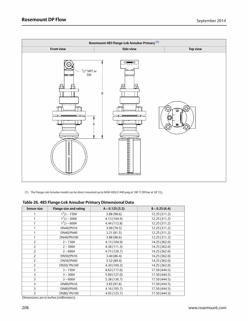
Rosemount 485 Flange-Lok Annubar Primary (1)
Front view Side view Top view
(1) The Flange-Lok Annubar model can be direct mounted up to 600# ANSI (1440 psig at 100 °F (99 bar at 38 °C)).
Table 26. 485 Flange-Lok Annubar Primary Dimensional Data
Sensor size Flange size and rating A ± 0.125 (3.2) B ± 0.25 (6.4)
1 11/2 – 150# 3.88 (98.6) 12.25 (311.2)1 11/2 – 300# 4.13 (104.9) 12.25 (311.2)1 11/2 – 600# 4.44 (112.8) 12.25 (311.2)1 DN40/PN16 3.09 (78.5) 12.25 (311.2)1 DN40/PN40 3.21 (81.5) 12.25 (311.2)1 DN40/PN100 3.88 (98.6) 12.25 (311.2)2 2 – 150# 4.13 (104.9) 14.25 (362.0)2 2 – 300# 4.38 (111.3) 14.25 (362.0)2 2 – 600# 4.75 (120.7) 14.25 (362.0)2 DN50/PN16 3.40 (86.4) 14.25 (362.0)2 DN50/PN40 3.52 (89.4) 14.25 (362.0)2 DN50/ PN100 4.30 (109.2) 14.25 (362.0)3 3 – 150# 4.63 (117.6) 17.50 (444.5)3 3 – 300# 5.00 (127.0) 17.50 (444.5)3 3 – 600# 5.38 (136.7) 17.50 (444.5)3 DN80/PN16 3.85 (97.8) 17.50 (444.5)3 DN80/PN40 4.16 (105.7) 17.50 (444.5)3 DN80/ PN100 4.95 (125.7) 17.50 (444.5)
Dimensions are in inches (millimeters).
B
A
1/2” NPT or SW

209
Rosemount DP FlowSeptember 2014
www.rosemount.com
Rosemount 485 Flanged Annubar Primary
Front view Side view Top view
Table 27. 485 Flanged Annubar Primary Dimensional Data
Sensor size Flange size and rating A ± 0.125 (3.2) B ± 0.25 (6.4) F (Max)
1 11/2 – 150# 3.88 (98.6) 11.00 (279.4) 3.50 (88.9)1 11/2 – 300# 4.13 (104.9) 11.00 (279.4) 3.50 (88.9)1 11/2 – 600# 4.44 (112.8) 11.00 (279.4) 3.50 (88.9)1 DN40/PN16 3.09 (78.5) 11.00 (279.4) 3.50 (88.9)1 DN40/PN40 3.21 (81.5) 11.00 (279.4) 3.50 (88.9)1 DN40/ PN100 3.88 (98.6) 11.00 (279.4) 3.50 (88.9)1 11/2 – 900# 4.94 (125.5) 9.31 (236.5) 3.50 (88.9)1 11/2 – 1500# 4.94 (125.5) 9.31 (236.5) 3.50 (88.9)1 11/2 – 2500# 6.76 (171.7) 11.63 (295.4) 4.00 (101.6)2 2 – 150# 4.13 (104.9) 12.00 (304.8) 5.00 (127.0)2 2 – 300# 4.38 (111.3) 12.00 (304.8) 5.00 (127.0)2 2 – 600# 4.75 (120.7) 12.00 (304.8) 5.00 (127.0)2 DN50/PN16 3.40 (86.4) 12.00 (304.8) 5.00 (127.0)2 DN50/PN40 3.52 (89.4) 12.00 (304.8) 5.00 (127.0)2 DN50/ PN100 4.30 (109.2) 12.00 (304.8) 5.00 (127.0)2 2 – 900# 5.88 (149.4) 10.50 (266.7) 5.00 (127.0)2 2 – 1500# 5.88 (149.4) 10.50 (266.7) 5.00 (127.0)2 3 – 2500# 9.88 (251.0) 15.63 (397.0) 4.50 (114.3)3 3 – 150# 4.63 (117.6) 13.50 (342.9) 4.00 (101.6)3 3 – 300# 5.00 (127.0) 13.50 (342.9) 4.00 (101.6)3 3 – 600# 5.38 (136.7) 13.50 (342.9) 4.00 (101.6)3 DN80/PN16 3.85 (97.8) 13.50 (342.9) 4.00 (101.6)3 DN80/PN40 4.16 (105.7) 13.50 (342.9) 4.00 (101.6)3 DN80/ PN100 4.95 (125.7) 13.50 (342.9) 4.00 (101.6)3 4 – 900# 8.19 (208.0) 13.06 (331.7) 7.00 (177.8)3 4 – 1500# 8.56 (217.4) 13.81 (350.8) 7.00 (177.8)3 4 – 2500# 11.19 (284.2) 17.31 (439.7) 7.00 (177.8)
Dimensions are in inches (millimeters).
B
A
F
1/2” NPTOR SW

210
Rosemount DP Flow September 2014
www.rosemount.com
Rosemount 485 Flanged Flo-Tap Annubar Primary
Front view Side view Top view
Front view Side view Top view
A
B
C
1/2” NPT or SW
D
C
BA
MANUAL 1/2” NPTOR SW
D
Table 28. 485 Flanged Flo-Tap Annubar Primary Dimensional Data
Sensor sizeFlange size and rating A ± 0.125 (3.2) B ± 0.25 (6.4)
CI (Max)(gear drive)
CI (Max)(manual) D (Max)
1 11/2 – 150# 3.88 (98.6) 10.50 (266.7) N/A 17.77 (451.4) 10.50 (266.7)1 11/2 – 300# 4.13 (104.9) 11.75 (298.5) N/A 17.77 (451.4) 10.50 (266.7)1 11/2 – 600# 4.44 (112.8) 14.06 (357.2) N/A 17.77 (451.4) 10.50 (266.7)1 DN40/PN16 3.09 (78.5) (1) N/A 17.77 (451.4) 10.50 (266.7)
1 DN40/PN40 3.21 (81.5) (3) N/A 17.77 (451.4) 10.50 (266.7)1 DN40/PN100 3.88 (98.6) (3) N/A 17.77 (451.4) 10.50 (266.7)
2 2 – 150# 4.13 (104.9) 11.25 (285.8) 24.44 (620.8) 21.20 (538.5) 12.56 (319.0)2 2 – 300# 4.38 (111.3) 13.00 (330.2) 24.44 (620.8) 21.20 (538.5) 12.56 (319.0)2 2 – 600# 4.75 (120.7) 16.38 (416.0) 24.44 (620.8) 21.20 (538.5) 12.56 (319.0)2 DN50/PN16 3.40 (86.4) (3) 24.44 (620.8) 21.20 (538.5) 12.56 (319.0)
2 DN50/PN40 3.52 (89.4) (3) 24.44 (620.8) 21.20 (538.5) 12.56 (319.0)
2 DN50/PN100 4.30 (109.2) (3) 24.44 (620.8) 21.20 (538.5) 12.56 (319.0)
3 3 – 150# 4.63 (117.6) 12.75 (323.9) 26.37 (669.8) 23.14 (587.8) 14.13 (358.9)3 3 – 300# 5.00 (127.0) 16.25 (412.8) 26.37 (669.8) 23.14 (587.8) 14.13 (358.9)3 3 – 600# 5.38 (136.7) 19.50 (495.4) 26.37 (669.8) 23.14 (587.8) 14.13 (358.9)3 DN80/PN16 3.85 (97.8) (3) 26.37 (669.8) 23.14 (587.8) 14.13 (358.9)
3 DN80/PN40 4.16 (105.7) (3) 26.37 (669.8) 23.14 (587.8) 14.13 (358.9)
3 DN80/PN100 4.95 (125.7) (3) 26.37 (669.8) 23.14 (587.8) 14.13 (358.9)
Use the appropriate formula to determine C value: Inserted formula: Pipe I.D. + Wall Thickness + Value B + C1 (use the Manual Drive or Gear drive values for C1)Retracted formula: [2 x (Pipe I.D. + Wall Thickness + Value B)] + C1 (use the Manual Drive or Gear drive values for C1)Dimensions are in inches (millimeters).
(1) DIN Valves are not offered.

211
Rosemount DP FlowSeptember 2014
www.rosemount.com
Rosemount 485 Threaded Flo-Tap Annubar Primary
Front view Side view Top view
Front view Side view Top view
Table 29. 485 Threaded Flo-Tap Annubar Primary Dimensional Data(1)(2)
Sensor size A ± 0.50 (12.7)BI (Max)
(gear drive)BI (Max)
(manual) D (Max)
1 7.51 (190.9) N/A 16.96 (430.8) 10.50 (266.7)2 8.17 (207.5) 23.62 (599.9) 20.39 (517.9) 12.56 (319.0)
3(3) N/A N/A N/A N/A
(1) Inserted, B Dimension = Pipe I.D. + Wall Thickness + A + BI
(2) Retracted, B Dimension = 2 x (Pipe I.D. + Wall Thickness + A) + BI
(3) Sensor Size 3 is not available in a Threaded Flo-Tap.
GEAR DRIVE
B
1/2”NPT OR SW
A
D
B
A
MANUAL 1/2”NPT OR SW
D