Product Data Sheet 00813-0100-4360, Rev DB October …elo373/Transmisor1151.pdf · Product Data...
24
Product Data Sheet 00813-0100-4360, Rev DB October 2003 Rosemount 1151 www.rosemount.com Proven field performance and reliability Commitment to continuous improvement Application flexibility Content Specifications . . . . . . . . . . . . . . . . . . . . . . . . . . . . . . . . . . . . . . . . . . . . . . . . . . . . . . page 3 Product Certifications . . . . . . . . . . . . . . . . . . . . . . . . . . . . . . . . . . . . . . . . . . . . . . . . page 7 Dimensional Drawings. . . . . . . . . . . . . . . . . . . . . . . . . . . . . . . . . . . . . . . . . . . . . . . . page 9 Ordering Information . . . . . . . . . . . . . . . . . . . . . . . . . . . . . . . . . . . . . . . . . . . . . . . . page 15 Rosemount 1151 Pressure Transmitter
Transcript of Product Data Sheet 00813-0100-4360, Rev DB October …elo373/Transmisor1151.pdf · Product Data...
Product Data Sheet00813-0100-4360, Rev DBOctober 2003 Rosemount 1151
www.rosemount.com
� Proven field performance and reliability
� Commitment to continuous improvement
� Application flexibility
ContentSpecifications . . . . . . . . . . . . . . . . . . . . . . . . . . . . . . . . . . . . . . . . . . . . . . . . . . . . . . page 3
Product Certifications . . . . . . . . . . . . . . . . . . . . . . . . . . . . . . . . . . . . . . . . . . . . . . . . page 7
Dimensional Drawings. . . . . . . . . . . . . . . . . . . . . . . . . . . . . . . . . . . . . . . . . . . . . . . . page 9
Ordering Information . . . . . . . . . . . . . . . . . . . . . . . . . . . . . . . . . . . . . . . . . . . . . . . . page 15
Rosemount 1151 Pressure Transmitter
Product Data Sheet00813-0100-4360, Rev DB
October 2003Rosemount 1151
2
Leading a tradition of excellence
With over five million transmitters installed worldwide, the 1151 continues to offer industry leading value. Changing customer needs have driven product improvements, while advanced manufacturing and testing processes have guaranteed product quality. Even today, the 1151 is world-renowned for proven field reliability and longevity.
Proven field performance and reliability
For over 30 years, the 1151 has provided the process control industry with unsurpassed service and reliability in even the harshest of environments. The lasting customer preference results from a combination of advanced technology, and a heritage of field proven performance.
Commitment to continuous improvement
Smart electronics increased rangeability to 40:1, reducing the number of transmitters to specify, procure and carry in inventory. In addition, ± 0.1% accuracy has been achieved through product improvements, meeting ever increasing pressure measurement requirements. A modular design allows interchangeable mechanical and electrical components, providing backward and forward compatibility.
Application flexibility
The 1151 offers a variety of configurations for differential, gage, absolute and liquid- level measurements. A high pressure models allows static line pressures up to 4500 psi (310 bar). Multiple wetted materials, as well as alternative fill fluids ensure process compatibility. Smart, analog and low-power electronics are available to meet specific application requirements.
Rosemount Pressure SolutionsRosemount 3051S Series of InstrumentationScalable pressure, flow and level measurement solutions improve installation and maintenance practices.
Rosemount 3095MV Mass Flow TransmitterAccurately measures differential pressure, static pressure and process temperature to dynamically calculate fully compensated mass flow.
Rosemount 305 and 306 Integral ManifoldsFactory-assembled, calibrated and seal-tested manifolds reduce on-site installation costs.
Rosemount 1199 Diaphragm SealsProvides reliable, remote measurements of process pressure and protects the transmitter from hot, corrosive, or viscous fluids.
Orifice Plate Primary Element Systems: Rosemount 1495 and 1595 Orifice Plates, 1496 Flange Unions and 1497 Meter SectionsA comprehensive offering of orifice plates, flange unions and meter sections that is easy to specify and order. The 1595 Conditioning Orifice provides superior performance in tight fit applications.
Annubar Flowmeter Series: Rosemount 3051SFA, 3095MFA, and 485The state-of-the-art, fifth generation Rosemount 485 Annubar combined with the 3051S or 3095MV MultiVariable transmitter creates an accurate, repeatable and dependable insertion-type flowmeter.
Compact Orifice Flowmeter Series: Rosemount 3051SFC, 3095MFC, and 405 Compact Orifice Flowmeters can be installed between existing flanges, up to a Class 600 (PN100) rating. In tight fit applications, a conditioning orifice plate version is available, requiring only two diameters of straight run upstream.
ProPlate Flowmeter Series: Rosemount ProPlate, Mass ProPlate, and 1195These integral orifice flowmeters eliminate the inaccuracies that become more pronounced in small orifice line installations. The completely assembled, ready to install flowmeters reduce cost and simplify installation.
Product Data Sheet00813-0100-4360, Rev DBOctober 2003
3
Rosemount 1151
Specifications
FUNCTIONAL SPECIFICATIONS
ServiceLiquid, gas, and vapor applications
RangesSee Table 2 for ranges. Minimum span equals the upper range limit (URL) divided by rangedown. Rangedown varies with the output code See Table 1.
OutputsCode S, Smart
4�20 mA dc, user selectable for linear or square root output. Digital process variable superimposed on 4�20 mA signal, available to any host that conforms to the HART® protocol.
Code E, Analog4�20 mA dc, linear with process pressure
Code G, Analog10�50 mA dc, linear with process pressure
Code J, Analog4�20 mA dc, square root of differential input pressure between 4 and 100% of input. Linear with differential input pressure between 0 and 4% of input.
Code L, Low Power0.8 to 3.2 V dc, linear with process pressure
Code M, Low Power1 to 5 V dc, linear with process pressure
Current Consumption Under Normal Operating Conditions (Low Power Only)Output Code L
1.5 mA dcOutput Code M
2.0 mA dc
Zero Elevation and SuppressionOutput Codes S, E, and G
Zero elevation and suppression must be such that the lower range value is greater than or equal to the (�URL) and the upper range value is less than or equal to the (+URL). The calibrated span must be greater than or equal to the minimum span and less than or equal to the maximum span.
Output Code JZero is adjustable up to 10% of the calibrated flow span.
Output Code LZero is adjustable ±10% of URL and span is adjustable from 90 to 100% of URL.
Output Code MZero is adjustable ±50% of URL and span is adjustable from 50 to 100% of URL.
Span and ZeroOutput Code S
Span and zero may be accessed with local adjustments or remotely through a HART-compatible Interface.
Output Codes E, G, J, L, and MSpan and zero are continuously adjustable.
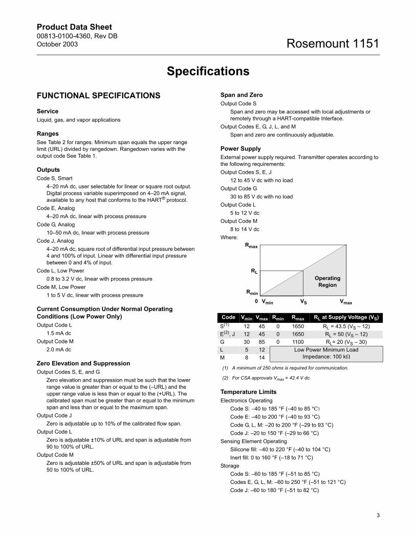
Power SupplyExternal power supply required. Transmitter operates according to the following requirements:Output Codes S, E, J
12 to 45 V dc with no loadOutput Code G
30 to 85 V dc with no loadOutput Code L
5 to 12 V dcOutput Code M
8 to 14 V dcWhere:
Temperature LimitsElectronics Operating
Code S: –40 to 185 °F (�40 to 85 °C)Code E: �40 to 200 °F (�40 to 93 °C)Code G, L, M: �20 to 200 °F (�29 to 93 °C)Code J: �20 to 150 °F (�29 to 66 °C)
Sensing Element OperatingSilicone fill: �40 to 220 °F (�40 to 104 °C)Inert fill: 0 to 160 °F (�18 to 71 °C)
StorageCode S: �60 to 185 °F (�51 to 85 °C)Codes E, G, L, M: �60 to 250 °F (�51 to 121 °C)Code J: �60 to 180 °F (�51 to 82 °C)
Code Vmin Vmax Rmin Rmax RL at Supply Voltage (VS)S(1)
(1) A minimum of 250 ohms is required for communication.
12 45 0 1650 RL = 43.5 (VS � 12)E(2), J
(2) For CSA approvals Vmax = 42.4 V dc.
12 45 0 1650 RL = 50 (VS � 12)G 30 85 0 1100 RL= 20 (VS � 30)L 5 12 Low Power Minimum Load
Impedance: 100 k�M 8 14
Rmax
RL
Rmin
Vmin VS Vmax0
Operating Region
Product Data Sheet00813-0100-4360, Rev DB
October 2003Rosemount 1151
4
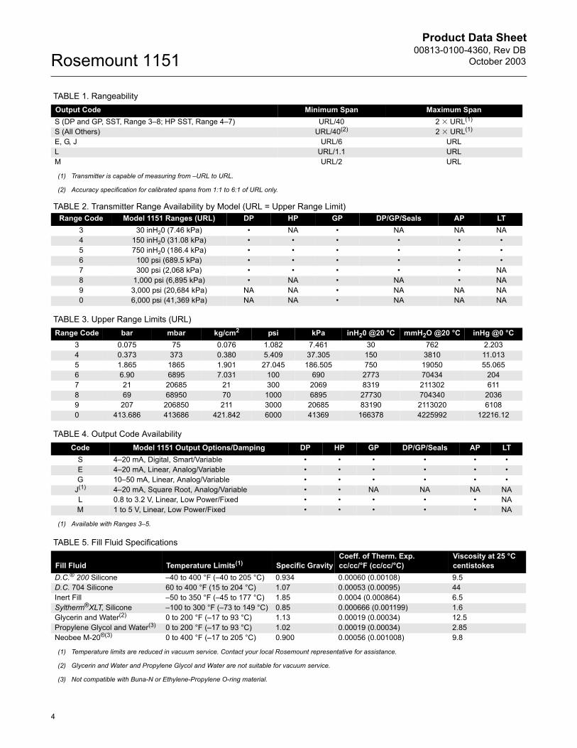
TABLE 1. Rangeability
TABLE 2. Transmitter Range Availability by Model (URL = Upper Range Limit)
TABLE 3. Upper Range Limits (URL)
TABLE 4. Output Code Availability
TABLE 5. Fill Fluid Specifications
Output Code Minimum Span Maximum SpanS (DP and GP, SST, Range 3�8; HP SST, Range 4�7) URL/40 2 � URL(1)
S (All Others) URL/40(2) 2 � URL(1)
E, G, J URL/6 URLL URL/1.1 URLM URL/2 URL
(1) Transmitter is capable of measuring from �URL to URL.
(2) Accuracy specification for calibrated spans from 1:1 to 6:1 of URL only.
Range Code Model 1151 Ranges (URL) DP HP GP DP/GP/Seals AP LT3 30 inH20 (7.46 kPa) � NA � NA NA NA4 150 inH20 (31.08 kPa) � � � � � �5 750 inH20 (186.4 kPa) � � � � � �6 100 psi (689.5 kPa) � � � � � �7 300 psi (2,068 kPa) � � � � � NA8 1,000 psi (6,895 kPa) � NA � NA � NA9 3,000 psi (20,684 kPa) NA NA � NA NA NA0 6,000 psi (41,369 kPa) NA NA � NA NA NA
Range Code bar mbar kg/cm2 psi kPa inH20 @20 °C mmH2O @20 °C inHg @0 °C3 0.075 75 0.076 1.082 7.461 30 762 2.2034 0.373 373 0.380 5.409 37.305 150 3810 11.0135 1.865 1865 1.901 27.045 186.505 750 19050 55.0656 6.90 6895 7.031 100 690 2773 70434 2047 21 20685 21 300 2069 8319 211302 6118 69 68950 70 1000 6895 27730 704340 20369 207 206850 211 3000 20685 83190 2113020 61080 413.686 413686 421.842 6000 41369 166378 4225992 12216.12
Code Model 1151 Output Options/Damping DP HP GP DP/GP/Seals AP LTS 4�20 mA, Digital, Smart/Variable � � � � � �E 4�20 mA, Linear, Analog/Variable � � � � � �G 10�50 mA, Linear, Analog/Variable � � � � � �
J(1) 4�20 mA, Square Root, Analog/Variable � � NA NA NA NAL 0.8 to 3.2 V, Linear, Low Power/Fixed � � � � � NAM 1 to 5 V, Linear, Low Power/Fixed � � � � � NA
(1) Available with Ranges 3�5.
Fill Fluid Temperature Limits(1) Specific GravityCoeff. of Therm. Exp.cc/cc/°F (cc/cc/°C)
Viscosity at 25 °Ccentistokes
D.C.® 200 Silicone �40 to 400 °F (�40 to 205 °C) 0.934 0.00060 (0.00108) 9.5D.C. 704 Silicone 60 to 400 °F (15 to 204 °C) 1.07 0.00053 (0.00095) 44Inert Fill �50 to 350 °F (�45 to 177 °C) 1.85 0.0004 (0.000864) 6.5Syltherm®XLT, Silicone �100 to 300 °F (�73 to 149 °C) 0.85 0.000666 (0.001199) 1.6Glycerin and Water(2) 0 to 200 °F (�17 to 93 °C) 1.13 0.00019 (0.00034) 12.5Propylene Glycol and Water(3) 0 to 200 °F (�17 to 93 °C) 1.02 0.00019 (0.00034) 2.85Neobee M-20®(3) 0 to 400 °F (�17 to 205 °C) 0.900 0.00056 (0.001008) 9.8
(1) Temperature limits are reduced in vacuum service. Contact your local Rosemount representative for assistance.
(2) Glycerin and Water and Propylene Glycol and Water are not suitable for vacuum service.
(3) Not compatible with Buna-N or Ethylene-Propylene O-ring material.
Product Data Sheet00813-0100-4360, Rev DBOctober 2003
5
Rosemount 1151
Static Pressure and Overpressure LimitsModel 1151DP
0 psia to 2,000 psig (0 to 13.79 MPa) on either side without damage to transmitter. Operates within specifications from static line pressures of 0.5 psia (3.45 kPa) to 2,000 psig (13.79 MPa).
Model 1151HP0 psia to 4,500 psig (0 to 31.02 MPa) on either side without damage to transmitter. Operates within specifications from 0.5 psia (3.45 kPa) to 4,500 psig (31.02 MPa).
Model 1151AP0 psia to 2,000 psia (0 to 13.79 MPa) without damage to transmitter. Operates within specifications from 0 psia to the upper range limit of the transmitter.
Model 1151GP0 psia to 2,000 psig (0 to 13.79 MPa) for ranges to 1,000 psig (6.90 MPa), 4,500 psig (31.02 MPa) for the 3,000 psig (20.68 MPa) range, and 7,500 psig (51.71 MPa) for the 6,000 psig (41.37 MPa) range, without damage to the transmitter. Operates within specifications from 0.5 psia (3.45 kPa) to the upper range limit of the transmitter.
Model 1151LT
Burst Pressure All Models10,000 psig (68.95 MPa) proof pressure on the flanges.
Humidity Limits0 to 100% relative humidity
Volumetric DisplacementLess than 0.01 in3 (0.16 cm3)
Failure Mode Alarm (Output Code S)If self-diagnosis detects a gross transmitter failure, the analog signal will be driven below 3.9 mA or above 21 mA to alert the user. High or low alarm signal is user selectable.
Transmitter Security (Output Code S)Activating the transmitter security function prevents changes to the transmitter configuration, including local zero and span adjustments. Security is activated by an internal switch.
Overpressure Alarm (Output Code S)If the sensor detects a negative overpressure value, the analog signal will be driven to 3.9 mA. If the sensor detects a positive overpressure value, the analog signal is driven to 20.8 mA.
DampingNumbers given are for silicone fill fluid at room temperature. The minimum time constant is 0.2 seconds (0.4 seconds for Range 3). Inert-filled sensor values would be slightly higher.Output Code S
Time constant is adjustable in 0.1 second increments from minimum to 16.0 seconds.
Output Codes E and GTime constant continuously adjustable between minimum and 1.67 seconds.
Output Code JTime constant continuously adjustable between minimum and 1.0 second.
Output Codes L, MDamping is fixed at minimum time constant.
Model 1151LTTime constant continuously adjustable between 0.4 and 2.2 seconds with silicone oil fill, or 1.1 and 2.7 seconds with inert fill for flush models and electronics codes E or G.
Turn-on TimeMaximum of 2.0 seconds with minimum damping. Low power output is within 0.2% of steady state value within 200 ms after application of power.
PERFORMANCE SPECIFICATIONS(Zero-based calibrated ranges, reference conditions, silicone oil fill, 316 SST isolating diaphragms.)
AccuracyOutput Code S
Ranges 3 through 8, DP and GP transmitters;Ranges 4 through 7, HP transmitters±0.1 of calibrated span for spans from 1:1 to 10:1 of URL. Between 10:1 and 40:1 of URL.
All other ranges and transmitters±0.25% of calibrated span(1)
Output Code S, square root mode
Output Codes E, G, L, and M±0.2% of calibrated span for Model 1151DP Ranges 3 through 5. All other ranges and transmitters, ±0.25% of calibrated span.
Output Code J±0.25% of calibrated span
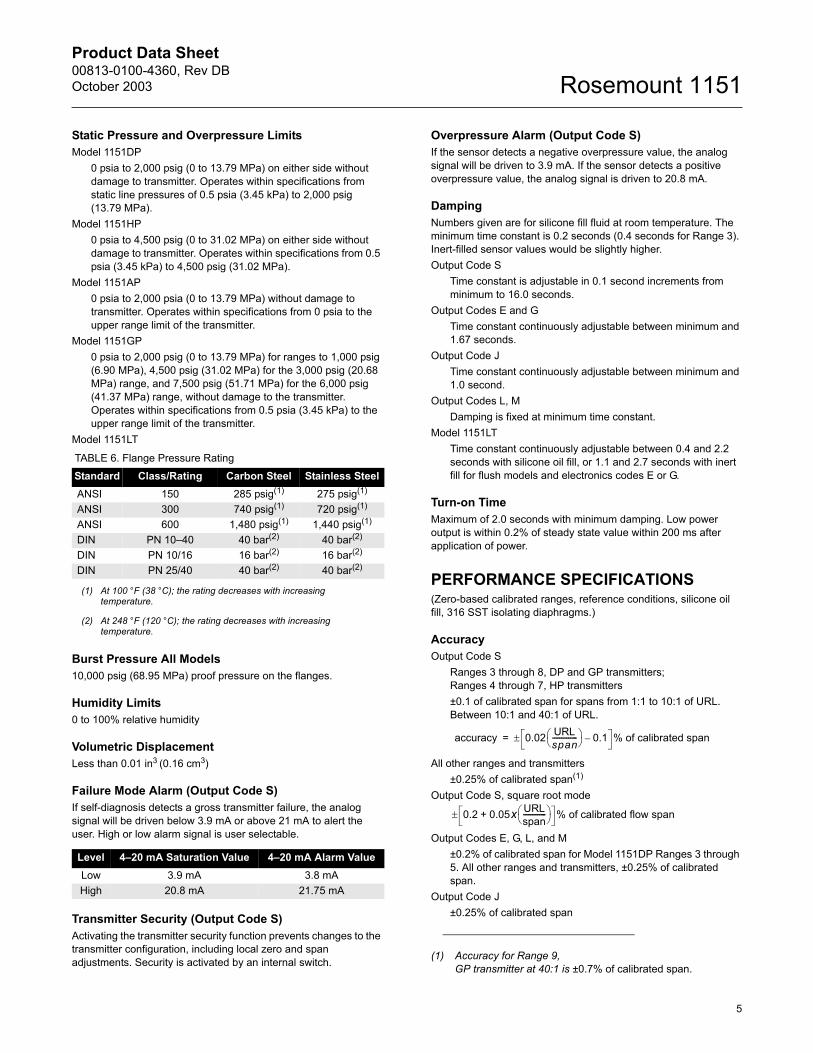
TABLE 6. Flange Pressure RatingStandard Class/Rating Carbon Steel Stainless SteelANSI 150 285 psig(1)
(1) At 100 °F (38 °C); the rating decreases with increasing temperature.
275 psig(1)
ANSI 300 740 psig(1) 720 psig(1)
ANSI 600 1,480 psig(1) 1,440 psig(1)
DIN PN 10�40 40 bar(2)
(2) At 248 °F (120 °C); the rating decreases with increasing temperature.
40 bar(2)
DIN PN 10/16 16 bar(2) 16 bar(2)
DIN PN 25/40 40 bar(2) 40 bar(2)
Level 4�20 mA Saturation Value 4�20 mA Alarm ValueLow 3.9 mA 3.8 mAHigh 20.8 mA 21.75 mA
(1) Accuracy for Range 9, GP transmitter at 40:1 is ±0.7% of calibrated span.
accuracy 0.02 URLspan--------------
0.1– % of calibrated span±=
0.2 0.05x URLspan-------------
+ % of calibrated flow span±
Product Data Sheet00813-0100-4360, Rev DB
October 2003Rosemount 1151
6
StabilityOutput Code S
±0.1% of URL for six months for DP and GP Ranges 3 through 8. (±0.25% for all other ranges and transmitters.)
Output Codes E and G±0.2% of URL for six months for Ranges 3 through 5. (±0.25 for all other ranges.)
Output Codes J, L, and M±0.25% of URL for six months
Temperature EffectOutput Code S [�20 to 185 °F (�29 to 85 °C)]
For DP and GP transmitter Range 4 through 8; HP transmitter Range 4 through 7:Zero Error = ±0.2% URL per 100 °F (56 °C)Total Error = ±(0.2% URL + 0.18% of calibrated span)per 100 °F; For Range 3, double the stated effects. For other ranges and transmitters follow analog temperature specifications (Output Code E).
Output Code E, G, L, and M[�20 to 200 °F (�29 to 93 °C)]For Ranges 4 through 0Zero Error = ±0.5% URL per 100 °F.Total Error = ±(0.5% URL + 0.5% of calibrated span) per 100 °F; double the effect for Range 3.
Output Code JThe total output effect, whether at zero or full scale, including zero and span errors is ±1.5% of URL per 100 °F (56 °C). ±2.5% of URL per 100 °F (56 °C) for Range 3.
Static Pressure Effect � DP TransmittersDP TransmittersZero Error
±0.25% of URL for 2,000 psi (13790 kPa) for Range 4 and 5 or ±0.5% for other ranges, correctable through rezeroing at line pressure.
Span ErrorCorrectable to ±0.25% of input reading per 1,000 psi (6895 kPa), or to ±0.5% for Range 3. For Output Code J, the span error is correctable to ±0.125% of output reading per 1,000 psi, or to ±0.25% for Range 3.
HP TransmittersZero Error
±2.0% of URL for 4,500 psi (31027 kPa), correctable through rezeroing at line pressure.
Span ErrorCorrectable to ±0.25% of input reading per 1,000 psi (6895 kPa). For Output Code J, the span error is correctable to ±0.125% of output reading per 1,000 psi.
Vibration Effect0.05% of URL per g to 200 Hz in any axis
Power Supply EffectOutput Codes S, E, G, and J
Less than 0.005% of output span per volt
Output Codes L, MOutput shift of less than 0.05% of URL for a 1 V power supply shift
Load EffectOutput Codes S, E, G, and J
No load effect other than the change in power supplied to the transmitter.
Output Codes L, MLess than 0.05% of URL effect for a change in load from 100k� to infinite ohms.
Short Circuit Condition (Low Power Only)No damage to the transmitter will result when the output is shorted to common or to power supply positive (limit 12 V).
EMI/RFI EffectOutput shift of less than 0.1% of span when tested to SAMA PMC 33.1 from 20 to 1000 MHz and for field strengths up to 30 V/m. (Code J is 0.1% of flow span.)
Mounting Position EffectZero shift of up to 1 inH2O (0.25 kPa). Range 3 transmitters with Output Code J should be installed with the diaphragm in the vertical plane.With liquid level diaphragm in vertical plane, zero shift of up to 1 inH2O (0.25 kPa). With liquid level diaphragm in horizontal plane, zero shift of up to 5 inH2O (1.25 kPa) plus extension length on extended units. All zero shifts can be calibrated out. No effect on span.
Physical Specifications,Standard Configuration
Electrical Connections1/2�14 NPT conduit with screw terminals and integral test jacks compatible with miniature banana plugs (Pomona 2944, 3690, or equivalent). The HART Hand-Held Interface connections are fixed to the terminal block on smart transmitters.
Wetted MaterialsIsolating Diaphragms
316L SST, Hastelloy® C-276®, or Tantalum. See ordering table for availability per model type.
Drain/Vent Valves316 SST or Hastelloy C®, see ordering table for availability per model type.
Process Flanges and AdaptersPlated carbon steel, 316 SST or Hastelloy C, see ordering table for availability per model type.
Wetted O-ringsViton® (other materials also available)
Weight12 lb (5.4 kg) for AP, DP, GP, and HP transmitters, excluding options. Meter option: Add 2 lb (1 kg)
Product Data Sheet00813-0100-4360, Rev DBOctober 2003
7
Rosemount 1151
Non-wetted MaterialsFill Fluid
Silicone oil or inert fillBolts and Bolting Flange (GP and AP only)
Plated carbon steelElectronics Housing
Low-copper aluminum. NEMA 4XCover O-rings
Buna-NPaint
Polyurethane
Process Connections1/4�18 NPT on 2.125-in. (54-mm) centers on flanges for Ranges 3, 4, and 5.1/4�18 NPT on 2.188-in. (56-mm) centers on flanges for Ranges 6 and 7.1/4�18 NPT on 2.250-in. (57-mm) centers on flanges for Range 8.1/2�14 NPT on adapters.For Ranges 3, 4, and 5, flange adapters can be rotated to give centers of 2.0 in. (51 mm), 2.125 in. (54 mm), or 2.250 in. (57 mm).)
Product Certifications
Approved Manufacturing LocationsRosemount Inc. � Chanhassen, Minnesota, USAFisher-Rosemount GmbH & Co. � Wessling, GermanyEmerson Process Management Asia Pacific Private Limited � SingaporeBeijing Rosemount Far East Instrument Co., Limited � Beijing, China
European Directive InformationThe EC declaration of conformity for all applicable European directives for this product can be found on the Rosemount website at www.rosemount.com. A hard copy may be obtained by contacting our local sales office.
ATEX Directive (94/9/EC)Emerson Process Management complies with the ATEX
Directive.
European Pressure Equipment Directive (PED) (97/23/EC)1151GP9, 0; 1151HP4, 5, 6, 7, 8 Pressure Transmitters� QS Certificate of Assessment - EC No. PED-H-20Module H Conformity Assessment
All other 1151 Pressure Transmitters� Sound Engineering Practice
Transmitter Attachments: Diaphragm Seal - Process Flange - Manifold� Sound Engineering Practice
Electro Magnetic Compatibility (EMC) (89/336/EEC)All models� EN 50081-1: 1992; EN 50082-2:1995;
Ordinary Location Certification for Factory MutualAs standard, the transmitter has been examined and tested to determine that the design meets basic electrical, mechanical, and fire protection requirements by FM, a nationally recognized testing laboratory (NRTL) as accredited by the Federal Occupational Safety and Health Administration (OSHA).
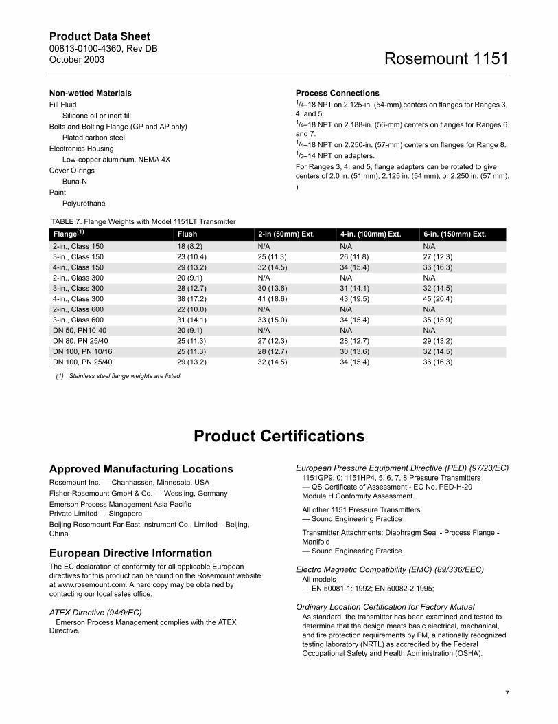
TABLE 7. Flange Weights with Model 1151LT TransmitterFlange(1) Flush 2-in (50mm) Ext. 4-in. (100mm) Ext. 6-in. (150mm) Ext.2-in., Class 150 18 (8.2) N/A N/A N/A3-in., Class 150 23 (10.4) 25 (11.3) 26 (11.8) 27 (12.3)4-in., Class 150 29 (13.2) 32 (14.5) 34 (15.4) 36 (16.3)2-in., Class 300 20 (9.1) N/A N/A N/A3-in., Class 300 28 (12.7) 30 (13.6) 31 (14.1) 32 (14.5)4-in., Class 300 38 (17.2) 41 (18.6) 43 (19.5) 45 (20.4)2-in., Class 600 22 (10.0) N/A N/A N/A3-in., Class 600 31 (14.1) 33 (15.0) 34 (15.4) 35 (15.9)DN 50, PN10-40 20 (9.1) N/A N/A N/ADN 80, PN 25/40 25 (11.3) 27 (12.3) 28 (12.7) 29 (13.2)DN 100, PN 10/16 25 (11.3) 28 (12.7) 30 (13.6) 32 (14.5)DN 100, PN 25/40 29 (13.2) 32 (14.5) 34 (15.4) 36 (16.3)
(1) Stainless steel flange weights are listed.
Product Data Sheet00813-0100-4360, Rev DB
October 2003Rosemount 1151
8
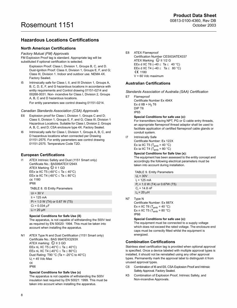
Hazardous Locations CertificationsNorth American CertificationsFactory Mutual (FM) ApprovalsFM Explosion Proof tag is standard. Appropriate tag will be substituted if optional certification is selected.
Explosion Proof: Class I, Division 1, Groups B, C, and D. Dust-Ignition Proof: Class II, Division 1, Groups E, F, and G; Class III, Division 1. Indoor and outdoor use. NEMA 4X. Factory Sealed.
I5 Intrinsically safe for Class I, II, and III Division 1, Groups A, B, C, D, E, F, and G hazardous locations in accordance with entity requirements and Control drawing 01151-0214 and 00268-0031. Non- incendive for Class I, Division 2, Groups A, B, C and D hazardous locations.For entity parameters see control drawing 01151-0214.
Canadian Standards Association (CSA) ApprovalsE6 Explosion proof for Class I, Division 1, Groups C and D;
Class II, Division 1, Groups E, F, and G; Class III, Division 1 Hazardous Locations. Suitable for Class I, Division 2, Groups A, B, C, and D; CSA enclosure type 4X. Factory Sealed.
I6 Intrinsically safe for Class I, Division 1, Groups A, B, C, and D hazardous locations when connected per Drawing 01151-2575. For entity parameters see control drawing 01151-2575. Temperature Code T2D.
European CertificationsI1 ATEX Intrinsic Safety and Dust (1151 Smart only)
Certificate No.: BAS99ATEX1294XATEX Marking II 1 GDEEx ia IIC T5 (-60°C ≤ Ta ≤ 40°C)EEx ia IIC T4 (-60°C ≤ Ta ≤ 80°C)
1180IP66
Special Conditions for Safe Use (X)The apparatus, is not capable of withstanding the 500V test as required by EN 50020: 1994. This must be taken into account when installing the apparatus.
N1 ATEX Type N and Dust Certification (1151 Smart only) Certificate No.: BAS 99ATEX3293XATEX marking: II 3 GDEEx nL IIC T5 (-40°C ≤ Ta ≤ 40°C)EEx nL IIC T4 (-40°C ≤ Ta ≤ 80°C)Dust Rating: T90 °C (Ta = -20°C to 40°C)Ui = 45 Vdc Max
IP66
Special Conditions for Safe Use (x)The apparatus is not capable of withstanding the 500V insulation test required by EN 50021: 1999. This must be taken into account when installing the apparatus.
E8 ATEX Flameproof Certification Number CESI03ATEX037ATEX Marking II 1/2 GEEx d IIC T6 (�40 ≤ Ta ≤ 40 °C)EEx d IIC T4 (�40 ≤ Ta ≤ 80 °C)
1180V = 60 Vdc maximum
Australian Certifications
Standards Association of Australia (SAA) CertificationE7 Flameproof
Certificate Number Ex 494XEx d IIB + H2 T6 DIP T6IP65Special Conditions for safe use (x):For transmitters having NPT, PG or G cable entry threads, an appropriate flameproof thread adaptor shall be used to facilitate application of certified flameproof cable glands or conduit system.
I7 Intrinsically SafeCertificate Number: Ex 122XEx ia IIC T5 (Tamb = 40 °C)Ex ia IIC T4 (Tamb = 80 °C)Special Conditions for Safe Use (x):The equipment has been assessed to the entity concept and accordingly the following electrical parameters must be taken into account during installation.
TABLE 9. Entity Parameters
N7 Type NCertificate Number: Ex 887XEx n IIC T6 (Tamb = 40 °C)Ex n IIC T5 (Tamb = 80 °C)IP66Special Conditions for safe use (x):The equipment must be connected to a supply voltage which does not exceed the rated voltage. The enclosure end caps must be correctly fitted whilst the equipment is energized.
Combination CertificationsStainless steel certification tag is provided when optional approval is specified. Once a device labeled with multiple approval types is installed, it should not be reinstalled using any other approval types. Permanently mark the approval label to distinguish it from unused approval types.C6 Combination of I6 and E6, CSA Explosion Proof and Intrinsic
Safety Approval. Factory Sealed.K5 Combination of Explosion Proof, Intrinsic Safety, and
Non-incendive Approvals.
TABLE 8. IS Entity ParametersUi = 30 VIi = 125 mAPi = 1.0 W (T4) or 0.67 W (T5)Ci = 0.034 µFLi = 20 µH
Ui = 30VIi = 125 mAPi = 1.0 W (T4) or 0.67W (T5)Ci = 14.8 nFLi = 20 µH
Product Data Sheet00813-0100-4360, Rev DBOctober 2003
9
Rosemount 1151
Dimensional Drawings
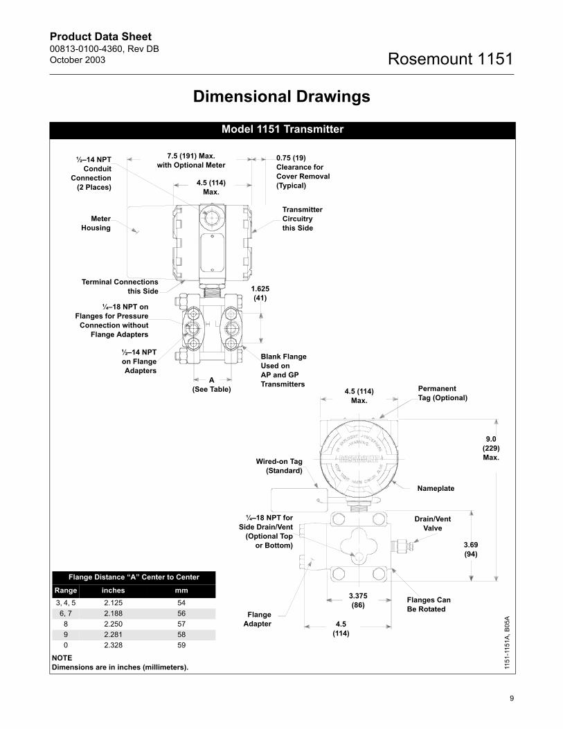
Model 1151 Transmitter
Flange Distance �A� Center to Center
Range inches mm3, 4, 5 2.125 546, 7 2.188 56
8 2.250 579 2.281 580 2.328 59
MeterHousing
Terminal Connectionsthis Side
¼�18 NPT onFlanges for Pressure
Connection withoutFlange Adapters
½�14 NPTon FlangeAdapters
A(See Table)
4.5 (114)Max.
7.5 (191) Max.with Optional Meter
0.75 (19)Clearance forCover Removal(Typical)
TransmitterCircuitrythis Side
1.625(41)
Blank FlangeUsed onAP and GP Transmitters
FlangeAdapter 4.5
(114)
3.375(86) Flanges Can
Be Rotated
3.69(94)
4.5 (114)Max.
PermanentTag (Optional)
Nameplate
Wired-on Tag(Standard)
Drain/VentValve
¼�18 NPT forSide Drain/Vent
(Optional Topor Bottom)
NOTEDimensions are in inches (millimeters). 11
51-1
151A
, B05
A
½�14 NPTConduit
Connection(2 Places)
9.0(229) Max.
Product Data Sheet00813-0100-4360, Rev DB
October 2003Rosemount 1151
10
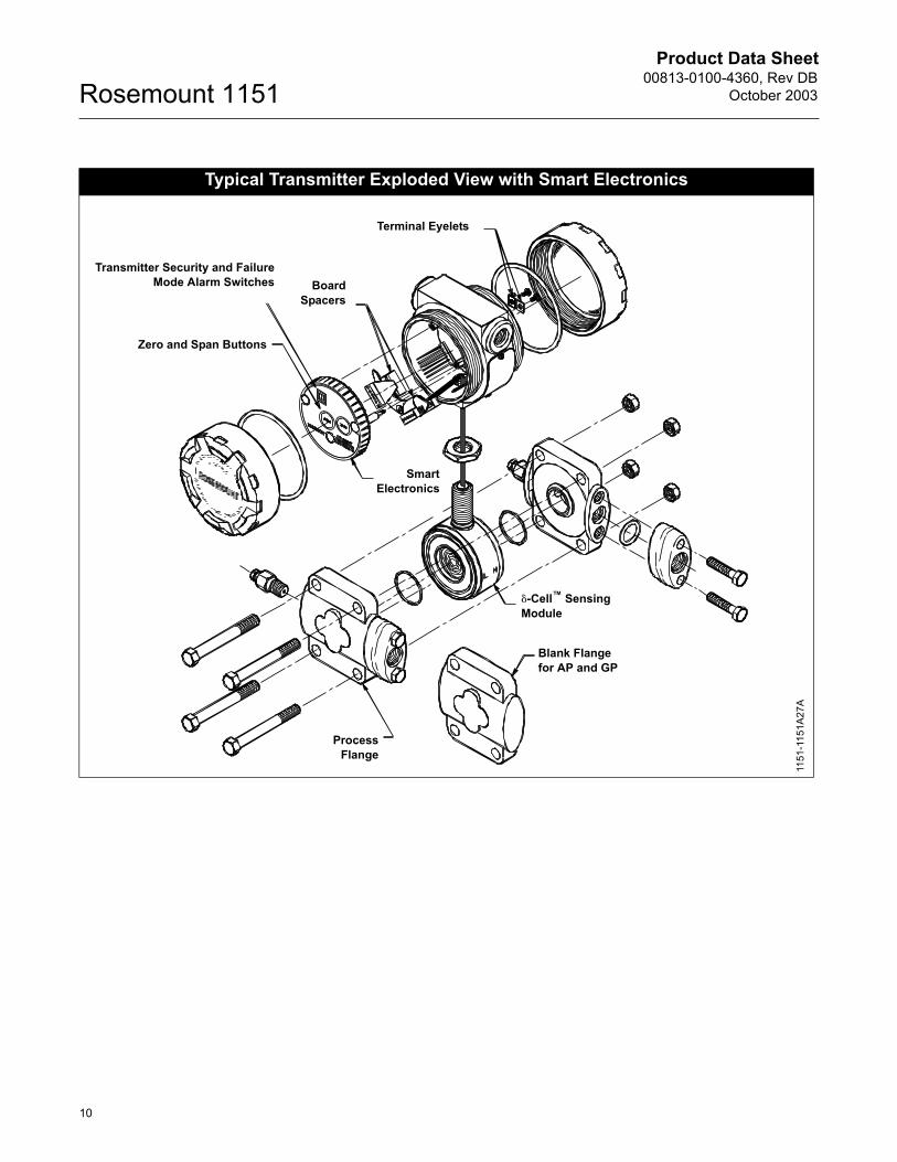
Typical Transmitter Exploded View with Smart Electronics
SmartElectronics
Terminal Eyelets
Transmitter Security and FailureMode Alarm Switches
Zero and Span Buttons
BoardSpacers
Blank Flangefor AP and GP
ProcessFlange
�-Cell� SensingModule
1151
-115
1A27
A
Product Data Sheet00813-0100-4360, Rev DBOctober 2003
11
Rosemount 1151
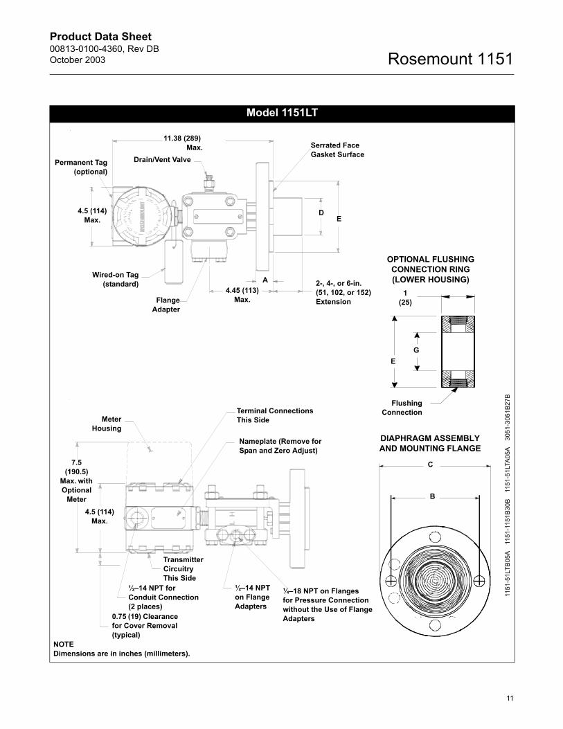
Model 1151LT
C
B
DIAPHRAGM ASSEMBLY AND MOUNTING FLANGE
NOTEDimensions are in inches (millimeters).
MeterHousing
Terminal ConnectionsThis Side
Nameplate (Remove for Span and Zero Adjust)
Transmitter Circuitry This Side
½�14 NPT forConduit Connection(2 places)
0.75 (19) Clearance for Cover Removal (typical)
½�14 NPTon FlangeAdapters
¼�18 NPT on Flangesfor Pressure Connectionwithout the Use of FlangeAdapters
Permanent Tag(optional)
11.38 (289) Max. Serrated Face
Gasket Surface
ED
AWired-on Tag(standard)
FlangeAdapter
2-, 4-, or 6-in.(51, 102, or 152)Extension
4.5 (114)Max.
4.5 (114)Max.
4.45 (113) Max.
1151
-51L
TB05
A11
51-1
151B
30B
1151
-51L
TA05
A30
51-3
051B
27B
7.5 (190.5)
Max. with Optional
Meter
FlushingConnection
1(25)
GE
OPTIONAL FLUSHING CONNECTION RING(LOWER HOUSING)
Drain/Vent Valve
Product Data Sheet00813-0100-4360, Rev DB
October 2003Rosemount 1151
12
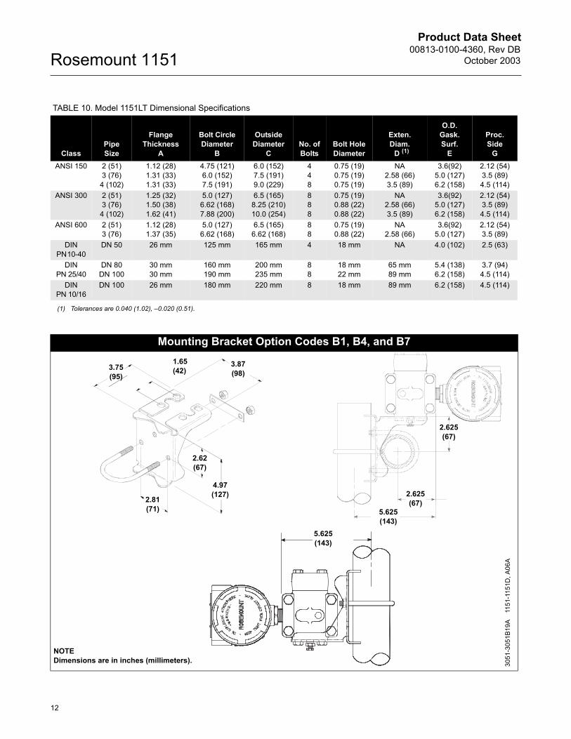
TABLE 10. Model 1151LT Dimensional Specifications
ClassPipe Size
Flange Thickness
A
Bolt Circle Diameter
B
Outside Diameter
CNo. of Bolts
Bolt Hole Diameter
Exten.Diam.
D (1)
O.D.Gask.Surf.
E
Proc. Side
GANSI 150 2 (51)
3 (76)4 (102)
1.12 (28)1.31 (33)1.31 (33)
4.75 (121)6.0 (152)7.5 (191)
6.0 (152)7.5 (191)9.0 (229)
448
0.75 (19)0.75 (19)0.75 (19)
NA2.58 (66)3.5 (89)
3.6(92)5.0 (127)6.2 (158)
2.12 (54)3.5 (89)4.5 (114)
ANSI 300 2 (51)3 (76)
4 (102)
1.25 (32)1.50 (38)1.62 (41)
5.0 (127)6.62 (168)7.88 (200)
6.5 (165)8.25 (210)10.0 (254)
888
0.75 (19)0.88 (22)0.88 (22)
NA2.58 (66)3.5 (89)
3.6(92)5.0 (127)6.2 (158)
2.12 (54)3.5 (89)4.5 (114)
ANSI 600 2 (51)3 (76)
1.12 (28)1.37 (35)
5.0 (127)6.62 (168)
6.5 (165)6.62 (168)
88
0.75 (19)0.88 (22)
NA2.58 (66)
3.6(92)5.0 (127)
2.12 (54)3.5 (89)
DINPN10-40
DN 50 26 mm 125 mm 165 mm 4 18 mm NA 4.0 (102) 2.5 (63)
DINPN 25/40
DN 80DN 100
30 mm30 mm
160 mm190 mm
200 mm235 mm
88
18 mm22 mm
65 mm89 mm
5.4 (138)6.2 (158)
3.7 (94)4.5 (114)
DINPN 10/16
DN 100 26 mm 180 mm 220 mm 8 18 mm 89 mm 6.2 (158) 4.5 (114)
(1) Tolerances are 0.040 (1.02), �0.020 (0.51).
Mounting Bracket Option Codes B1, B4, and B7
3.75 (95)
1.65 (42)
3.87 (98)
2.81 (71)
3051
-305
1B19
A11
51-1
151D
, A06
A
NOTEDimensions are in inches (millimeters).
4.97 (127)
2.62 (67)
2.625(67)
5.625(143)
2.625(67)
5.625(143)
Product Data Sheet00813-0100-4360, Rev DBOctober 2003
13
Rosemount 1151
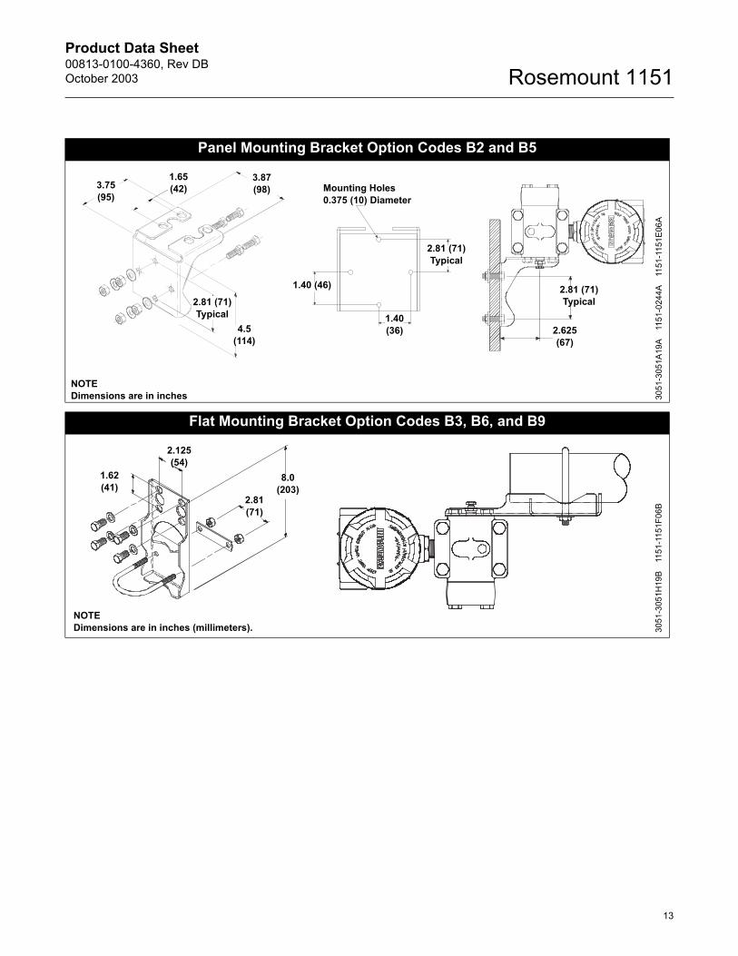
Panel Mounting Bracket Option Codes B2 and B5
Flat Mounting Bracket Option Codes B3, B6, and B9
2.625(67)
3.87 (98)
NOTEDimensions are in inches
1.40(36)
Mounting Holes 0.375 (10) Diameter
3.75 (95)
4.5 (114)
2.81 (71)Typical
1.40 (46)
2.81 (71)Typical
2.81 (71)Typical
1.65 (42)
3051
-305
1A19
A11
51-0
244A
1151
-115
1E06
A
8.0 (203)
1.62 (41)
2.81 (71)
2.125 (54)
NOTEDimensions are in inches (millimeters). 30
51-3
051H
19B
1151
-115
1F06
B
Product Data Sheet00813-0100-4360, Rev DB
October 2003Rosemount 1151
14
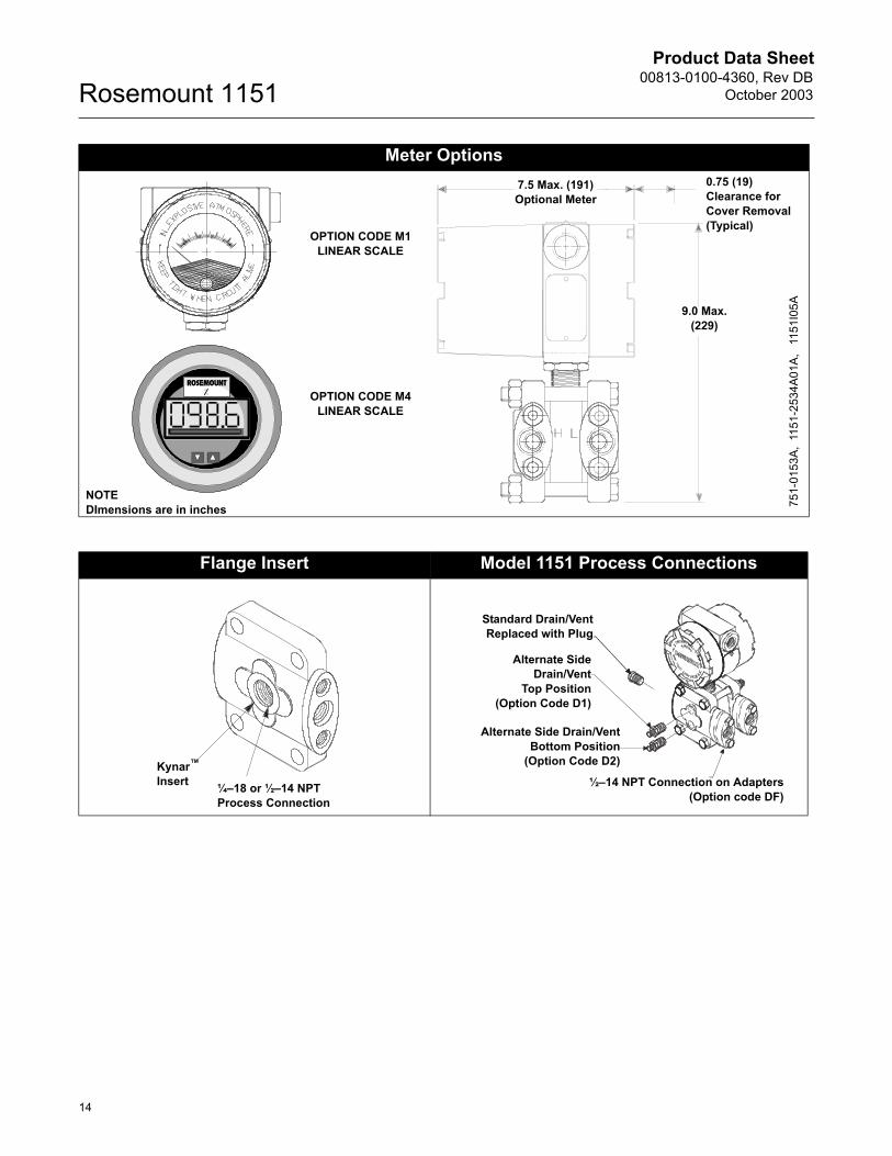
Meter Options
NOTEDImensions are in inches
7.5 Max. (191) Optional Meter
0.75 (19)Clearance forCover Removal(Typical)
9.0 Max. (229)
OPTION CODE M4LINEAR SCALE
OPTION CODE M1LINEAR SCALE
751-
0153
A,11
51-2
534A
01A,
11
51I0
5A
Flange Insert Model 1151 Process Connections
Kynar�
Insert ¼�18 or ½�14 NPTProcess Connection
½�14 NPT Connection on Adapters(Option code DF)
Standard Drain/VentReplaced with Plug
Alternate SideDrain/Vent
Top Position(Option Code D1)
Alternate Side Drain/VentBottom Position
(Option Code D2)
Product Data Sheet00813-0100-4360, Rev DBOctober 2003
15
Rosemount 1151
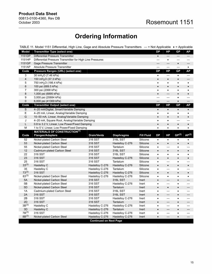
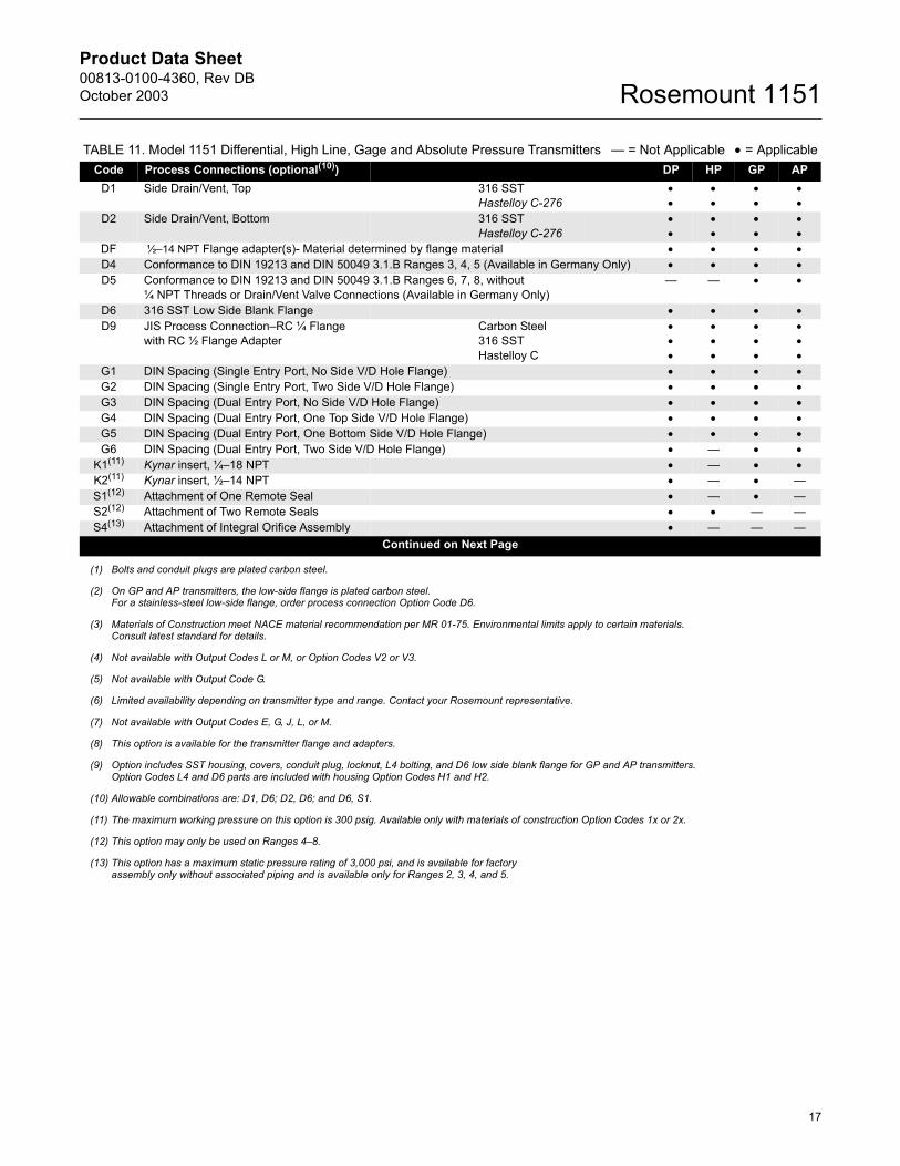
Ordering Information TABLE 11. Model 1151 Differential, High Line, Gage and Absolute Pressure Transmitters � = Not Applicable • = Applicable
Model Transmitter Type (select one) DP HP GP AP1151DP Differential Pressure Transmitter • � � �1151HP Differential Pressure Transmitter for High Line Pressures � • � �1151GP Gage Pressure Transmitter � � • �1151AP Absolute Pressure Transmitter � � � •Code Pressure Ranges (URL) (select one) DP HP GP AP
3 30 inH2O (7.46 kPa) • � • �4 150 inH2O (37.3 kPa) • • • �5 750 inH2O (186.4 kPa) • • • •6 100 psi (689.5 kPa) • • • •7 300 psi (2068 kPa) • • • •8 1,000 psi (6895 kPa) • � • •9 3,000 psi (20684 kPa) � � • �0 6,000 psi (41369 kPa) � � • �
Code Transmitter Output (select one) DP HP GP APS 4�20 mA/Digital, Smart/Variable Damping • • • •E 4�20 mA, Linear, Analog/Variable Damping • • • •G 10�50 mA, Linear, Analog/Variable Damping • • • •J 4�20 mA, Square Root, Analog/Variable Damping • • � �L 0.8 to 3.2 V, Linear, Low Power/Fixed Damping • • • •M 1 to 5 V, Linear, Low Power/Fixed Damping • • • •
CodeMATERIALS OF CONSTRUCTION(1)
Flanges/Adapters Drain/Vents Diaphragms Fill Fluid DP HP GP(2) AP(2)
52 Nickel-plated Carbon Steel 316 SST 316L SST Silicone • • • •53 Nickel-plated Carbon Steel 316 SST Hastelloy C-276 Silicone • • • •55 Nickel-plated Carbon Steel 316 SST Tantalum Silicone • � • �12 Cadmium-plated Carbon Steel 316 SST 316L SST Silicone • • • •22 316 SST 316 SST 316L SST Silicone • • • •23 316 SST 316 SST Hastelloy C-276 Silicone • • • •25 316 SST 316 SST Tantalum Silicone • � • �
33(3) Hastelloy C Hastelloy C-276 Hastelloy C-276 Silicone • • • •35 Hastelloy C Hastelloy C-276 Tantalum Silicone • � • �
73(3) 316 SST Hastelloy C-276 Hastelloy C-276 Silicone • • • •83(3) Nickel-plated Carbon Steel Hastelloy C-276 Hastelloy C-276 Silicone • • • •5A Nickel-plated Carbon Steel 316 SST 316L SST Inert • � • �5B Nickel-plated Carbon Steel 316 SST Hastelloy C-276 Inert • � • �5D Nickel-plated Carbon Steel 316 SST Tantalum Inert • • • �1A Cadmium-plated Carbon Steel 316 SST 316L SST Inert • � • �2A 316 SST 316 SST 316L SST Inert • � • �2B 316 SST 316 SST Hastelloy C-276 Inert • � • �2D 316 SST 316 SST Tantalum Inert • � • �
3B(3) Hastelloy C Hastelloy C-276 Hastelloy C-276 Inert • � • �3D Hastelloy C Hastelloy C-276 Tantalum Inert • � • �
7B(3) 316 SST Hastelloy C-276 Hastelloy C-276 Inert • � • �8B(3) Nickel-plated Carbon Steel Hastelloy C-276 Hastelloy C-276 Inert • � • �
Continued on Next Page
Product Data Sheet00813-0100-4360, Rev DB
October 2003Rosemount 1151
16
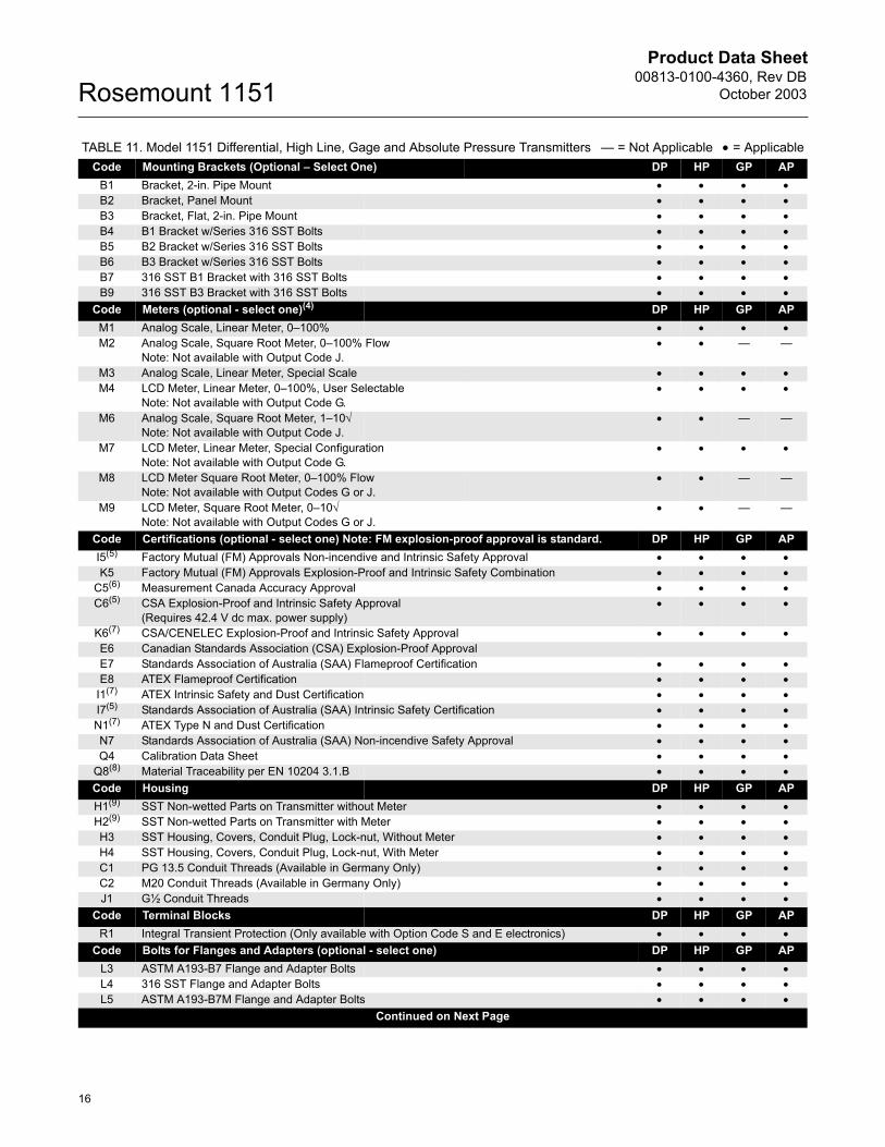
Code Mounting Brackets (Optional � Select One) DP HP GP APB1 Bracket, 2-in. Pipe Mount • • • •B2 Bracket, Panel Mount • • • •B3 Bracket, Flat, 2-in. Pipe Mount • • • •B4 B1 Bracket w/Series 316 SST Bolts • • • •B5 B2 Bracket w/Series 316 SST Bolts • • • •B6 B3 Bracket w/Series 316 SST Bolts • • • •B7 316 SST B1 Bracket with 316 SST Bolts • • • •B9 316 SST B3 Bracket with 316 SST Bolts • • • •
Code Meters (optional - select one)(4) DP HP GP APM1 Analog Scale, Linear Meter, 0�100% • • • •M2 Analog Scale, Square Root Meter, 0�100% Flow
Note: Not available with Output Code J.• • � �
M3 Analog Scale, Linear Meter, Special Scale • • • •M4 LCD Meter, Linear Meter, 0�100%, User Selectable
Note: Not available with Output Code G.• • • •
M6 Analog Scale, Square Root Meter, 1�10√Note: Not available with Output Code J.
• • � �
M7 LCD Meter, Linear Meter, Special ConfigurationNote: Not available with Output Code G.
• • • •
M8 LCD Meter Square Root Meter, 0�100% FlowNote: Not available with Output Codes G or J.
• • � �
M9 LCD Meter, Square Root Meter, 0�10√Note: Not available with Output Codes G or J.
• • � �
Code Certifications (optional - select one) Note: FM explosion-proof approval is standard. DP HP GP API5(5) Factory Mutual (FM) Approvals Non-incendive and Intrinsic Safety Approval • • • •K5 Factory Mutual (FM) Approvals Explosion-Proof and Intrinsic Safety Combination • • • •
C5(6) Measurement Canada Accuracy Approval • • • •C6(5) CSA Explosion-Proof and Intrinsic Safety Approval
(Requires 42.4 V dc max. power supply)• • • •
K6(7) CSA/CENELEC Explosion-Proof and Intrinsic Safety Approval • • • •E6 Canadian Standards Association (CSA) Explosion-Proof ApprovalE7 Standards Association of Australia (SAA) Flameproof Certification • • • •E8 ATEX Flameproof Certification • • • •
I1(7) ATEX Intrinsic Safety and Dust Certification • • • •I7(5) Standards Association of Australia (SAA) Intrinsic Safety Certification • • • •N1(7) ATEX Type N and Dust Certification • • • •N7 Standards Association of Australia (SAA) Non-incendive Safety Approval • • • •Q4 Calibration Data Sheet • • • •
Q8(8) Material Traceability per EN 10204 3.1.B • • • •Code Housing DP HP GP APH1(9) SST Non-wetted Parts on Transmitter without Meter • • • •H2(9) SST Non-wetted Parts on Transmitter with Meter • • • •H3 SST Housing, Covers, Conduit Plug, Lock-nut, Without Meter • • • •H4 SST Housing, Covers, Conduit Plug, Lock-nut, With Meter • • • •C1 PG 13.5 Conduit Threads (Available in Germany Only) • • • •C2 M20 Conduit Threads (Available in Germany Only) • • • •J1 G½ Conduit Threads • • • •
Code Terminal Blocks DP HP GP APR1 Integral Transient Protection (Only available with Option Code S and E electronics) • • • •
Code Bolts for Flanges and Adapters (optional - select one) DP HP GP APL3 ASTM A193-B7 Flange and Adapter Bolts • • • •L4 316 SST Flange and Adapter Bolts • • • •L5 ASTM A193-B7M Flange and Adapter Bolts • • • •
Continued on Next Page
TABLE 11. Model 1151 Differential, High Line, Gage and Absolute Pressure Transmitters � = Not Applicable • = Applicable
Product Data Sheet00813-0100-4360, Rev DBOctober 2003
17
Rosemount 1151
Code Process Connections (optional(10)) DP HP GP APD1 Side Drain/Vent, Top 316 SST
Hastelloy C-276••
••
••
••
D2 Side Drain/Vent, Bottom 316 SSTHastelloy C-276
••
••
••
••
DF ½�14 NPT Flange adapter(s)- Material determined by flange material • • • •D4 Conformance to DIN 19213 and DIN 50049 3.1.B Ranges 3, 4, 5 (Available in Germany Only) • • • •D5 Conformance to DIN 19213 and DIN 50049 3.1.B Ranges 6, 7, 8, without
¼ NPT Threads or Drain/Vent Valve Connections (Available in Germany Only)� � • •
D6 316 SST Low Side Blank Flange • • • •D9 JIS Process Connection�RC ¼ Flange
with RC ½ Flange AdapterCarbon Steel316 SSTHastelloy C
•••
•••
•••
•••
G1 DIN Spacing (Single Entry Port, No Side V/D Hole Flange) • • • •G2 DIN Spacing (Single Entry Port, Two Side V/D Hole Flange) • • • •G3 DIN Spacing (Dual Entry Port, No Side V/D Hole Flange) • • • •G4 DIN Spacing (Dual Entry Port, One Top Side V/D Hole Flange) • • • •G5 DIN Spacing (Dual Entry Port, One Bottom Side V/D Hole Flange) • • • •G6 DIN Spacing (Dual Entry Port, Two Side V/D Hole Flange) • � • •
K1(11) Kynar insert, ¼�18 NPT • � • •K2(11) Kynar insert, ½�14 NPT • � • �S1(12) Attachment of One Remote Seal • � • �S2(12) Attachment of Two Remote Seals • • � �S4(13) Attachment of Integral Orifice Assembly • � � �
Continued on Next Page
(1) Bolts and conduit plugs are plated carbon steel.
(2) On GP and AP transmitters, the low-side flange is plated carbon steel. For a stainless-steel low-side flange, order process connection Option Code D6.
(3) Materials of Construction meet NACE material recommendation per MR 01-75. Environmental limits apply to certain materials. Consult latest standard for details.
(4) Not available with Output Codes L or M, or Option Codes V2 or V3.
(5) Not available with Output Code G.
(6) Limited availability depending on transmitter type and range. Contact your Rosemount representative.
(7) Not available with Output Codes E, G, J, L, or M.
(8) This option is available for the transmitter flange and adapters.
(9) Option includes SST housing, covers, conduit plug, locknut, L4 bolting, and D6 low side blank flange for GP and AP transmitters.Option Codes L4 and D6 parts are included with housing Option Codes H1 and H2.
(10) Allowable combinations are: D1, D6; D2, D6; and D6, S1.
(11) The maximum working pressure on this option is 300 psig. Available only with materials of construction Option Codes 1x or 2x.
(12) This option may only be used on Ranges 4�8.
(13) This option has a maximum static pressure rating of 3,000 psi, and is available for factoryassembly only without associated piping and is available only for Ranges 2, 3, 4, and 5.
TABLE 11. Model 1151 Differential, High Line, Gage and Absolute Pressure Transmitters � = Not Applicable • = Applicable
Product Data Sheet00813-0100-4360, Rev DB
October 2003Rosemount 1151
18
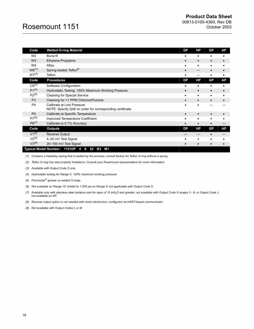
Code Wetted O-ring Material DP HP GP APW2 Buna-N • • • •W3 Ethylene-Propylene • • • •W4 Aflas • • • •
W6(1) Spring-loaded Teflon® • � • •W7(2) Teflon • � • •
Code Procedures DP HP GP APC9(3) Software Configuration • • • •P1(4) Hydrostatic Testing, 150% Maximum Working Pressure • • • •P2(5) Cleaning for Special Service • • • •P3 Cleaning for <1 PPM Chlorine/Fluorine • • • •P4 Calibrate at Line Pressure
NOTE: Specify Q48 on order for corresponding certificate.• • � �
P5 Calibrate at Specific Temperature • • • •P7(6) Improved Temperature Coefficient • • • •P8(7) Calibrate to 0.1% Accuracy • • • �Code Outputs DP HP GP APV1(8) Reverse Output � � • �V2(9) 4�20 mV Test Signal • • • •V3(9) 20�100 mV Test Signal • • • •
Typical Model Number: 1151DP 4 S 52 B3 M1
(1) Contains a Hastelloy spring that is wetted by the process; consult factory for Teflon O-ring without a spring.
(2) Teflon O-ring has seal property limitations; Consult your Rosemount representative for more information.
(3) Available with Output Code S only.
(4) Hydrostatic testing for Range 0, 125% maximum working pressure.
(5) Fluorolube® grease on wetted O-rings.
(6) Not available on Range 10: limited to 1,500 psi on Range 9; not applicable with Output Code S.
(7) Available only with stainless steel isolators and for span of 10 inH2O and greater; not available with Output Code S ranges 3 - 8, or Output Code J; not available on AP.
(8) Reverse output option is not needed with smart electronics; configured via HART-based communicator.
(9) Not available with Output Codes L or M.
Product Data Sheet00813-0100-4360, Rev DBOctober 2003
19
Rosemount 1151
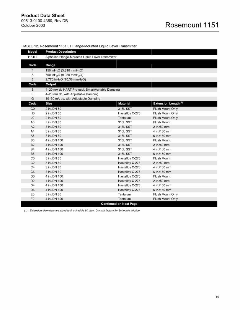
TABLE 12. Rosemount 1151 LT Flange-Mounted Liquid Level TransmitterModel Product Description1151LT Alphaline Flange-Mounted Liquid Level Transmitter
Code RangeRangeabilityOutput Code Min. Span
4 150 inH2O (3,810 mmH2O)5 750 inH2O (9,050 mmH2O)6 2,770 inH2O (70,36 mmH2O)
Code OutputS 4�20 mA dc HART Protocol, Smart/Variable DampingE 4�20 mA dc, with Adjustable DampingG 10�50 mA dc, with Adjustable Damping
Code Size Material Extension Length(1)
G0 2 in./DN 50 316L SST Flush Mount OnlyH0 2 in./DN 50 Hastelloy C-276 Flush Mount OnlyJ0 2 in./DN 50 Tantalum Flush Mount OnlyA0 3 in./DN 80 316L SST Flush MountA2 3 in./DN 80 316L SST 2 in./50 mmA4 3 in./DN 80 316L SST 4 in./100 mmA6 3 in./DN 80 316L SST 6 in./150 mmB0 4 in./DN 100 316L SST Flush MountB2 4 in./DN 100 316L SST 2 in./50 mmB4 4 in./DN 100 316L SST 4 in./100 mmB6 4 in./DN 100 316L SST 6 in./150 mmC0 3 in./DN 80 Hastelloy C-276 Flush MountC2 3 in./DN 80 Hastelloy C-276 2 in./50 mmC4 3 in./DN 80 Hastelloy C-276 4 in./100 mmC6 3 in./DN 80 Hastelloy C-276 6 in./150 mmD0 4 in./DN 100 Hastelloy C-276 Flush MountD2 4 in./DN 100 Hastelloy C-276 2 in./50 mmD4 4 in./DN 100 Hastelloy C-276 4 in./100 mmD6 4 in./DN 100 Hastelloy C-276 6 in./150 mmE0 3 in./DN 80 Tantalum Flush Mount OnlyF0 4 in./DN 100 Tantalum Flush Mount Only
Continued on Next Page
(1) Extension diameters are sized to fit schedule 80 pipe. Consult factory for Schedule 40 pipe.
Product Data Sheet00813-0100-4360, Rev DB
October 2003Rosemount 1151
20
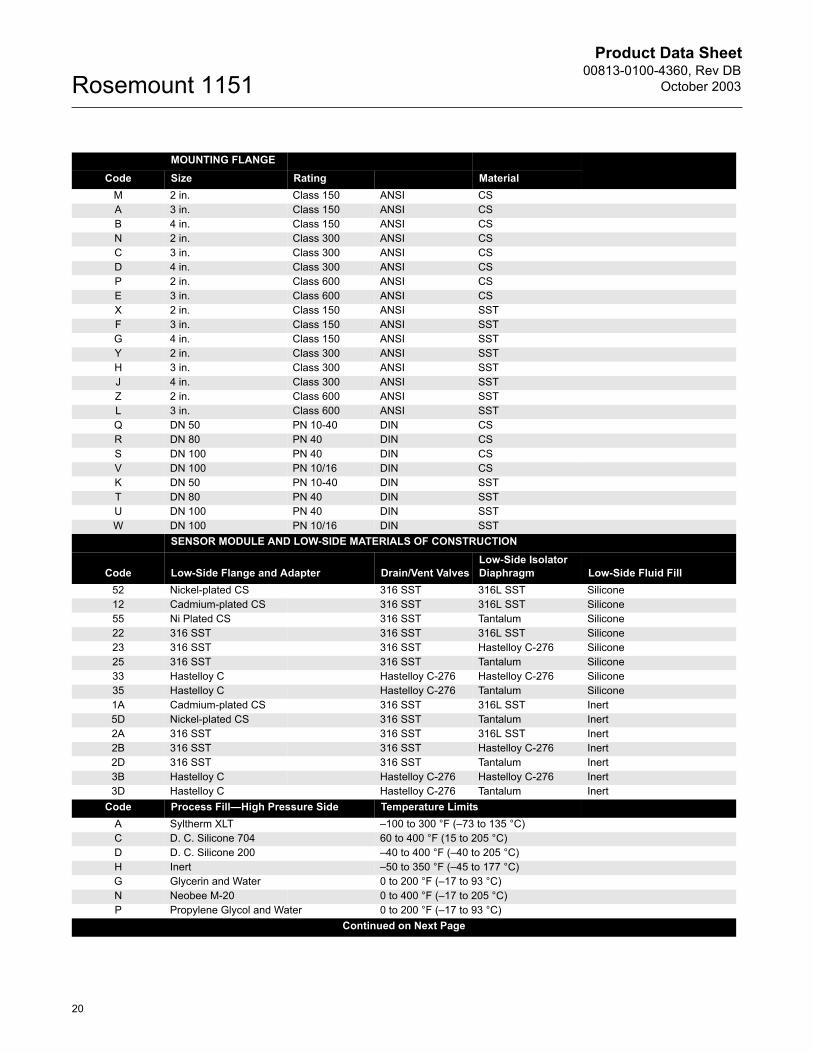
MOUNTING FLANGECode Size Rating Material
M 2 in. Class 150 ANSI CSA 3 in. Class 150 ANSI CSB 4 in. Class 150 ANSI CSN 2 in. Class 300 ANSI CSC 3 in. Class 300 ANSI CSD 4 in. Class 300 ANSI CSP 2 in. Class 600 ANSI CSE 3 in. Class 600 ANSI CSX 2 in. Class 150 ANSI SSTF 3 in. Class 150 ANSI SSTG 4 in. Class 150 ANSI SSTY 2 in. Class 300 ANSI SSTH 3 in. Class 300 ANSI SSTJ 4 in. Class 300 ANSI SSTZ 2 in. Class 600 ANSI SSTL 3 in. Class 600 ANSI SSTQ DN 50 PN 10-40 DIN CSR DN 80 PN 40 DIN CSS DN 100 PN 40 DIN CSV DN 100 PN 10/16 DIN CSK DN 50 PN 10-40 DIN SSTT DN 80 PN 40 DIN SSTU DN 100 PN 40 DIN SSTW DN 100 PN 10/16 DIN SST
SENSOR MODULE AND LOW-SIDE MATERIALS OF CONSTRUCTION
Code Low-Side Flange and Adapter Drain/Vent ValvesLow-Side Isolator Diaphragm Low-Side Fluid Fill
52 Nickel-plated CS 316 SST 316L SST Silicone12 Cadmium-plated CS 316 SST 316L SST Silicone55 Ni Plated CS 316 SST Tantalum Silicone22 316 SST 316 SST 316L SST Silicone23 316 SST 316 SST Hastelloy C-276 Silicone25 316 SST 316 SST Tantalum Silicone33 Hastelloy C Hastelloy C-276 Hastelloy C-276 Silicone35 Hastelloy C Hastelloy C-276 Tantalum Silicone1A Cadmium-plated CS 316 SST 316L SST Inert5D Nickel-plated CS 316 SST Tantalum Inert2A 316 SST 316 SST 316L SST Inert2B 316 SST 316 SST Hastelloy C-276 Inert2D 316 SST 316 SST Tantalum Inert3B Hastelloy C Hastelloy C-276 Hastelloy C-276 Inert3D Hastelloy C Hastelloy C-276 Tantalum Inert
Code Process Fill�High Pressure Side Temperature LimitsA Syltherm XLT �100 to 300 °F (�73 to 135 °C)C D. C. Silicone 704 60 to 400 °F (15 to 205 °C)D D. C. Silicone 200 �40 to 400 °F (�40 to 205 °C)H Inert �50 to 350 °F (�45 to 177 °C)G Glycerin and Water 0 to 200 °F (�17 to 93 °C)N Neobee M-20 0 to 400 °F (�17 to 205 °C)P Propylene Glycol and Water 0 to 200 °F (�17 to 93 °C)
Continued on Next Page
Product Data Sheet00813-0100-4360, Rev DBOctober 2003
21
Rosemount 1151
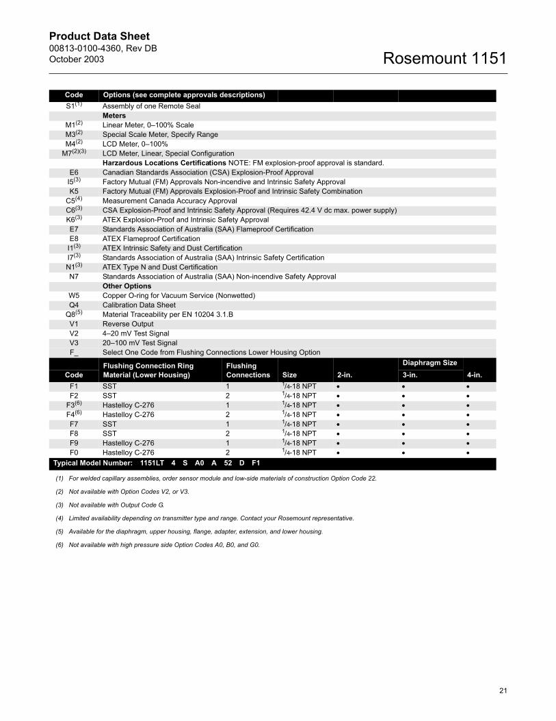
Code Options (see complete approvals descriptions)S1(1) Assembly of one Remote Seal
MetersM1(2) Linear Meter, 0�100% ScaleM3(2) Special Scale Meter, Specify RangeM4(2) LCD Meter, 0�100%
M7(2)(3) LCD Meter, Linear, Special ConfigurationHarzardous Locations Certifications NOTE: FM explosion-proof approval is standard.
E6 Canadian Standards Association (CSA) Explosion-Proof ApprovalI5(3) Factory Mutual (FM) Approvals Non-incendive and Intrinsic Safety ApprovalK5 Factory Mutual (FM) Approvals Explosion-Proof and Intrinsic Safety Combination
C5(4) Measurement Canada Accuracy ApprovalC6(3) CSA Explosion-Proof and Intrinsic Safety Approval (Requires 42.4 V dc max. power supply)K6(3) ATEX Explosion-Proof and Intrinsic Safety ApprovalE7 Standards Association of Australia (SAA) Flameproof CertificationE8 ATEX Flameproof Certification
I1(3) ATEX Intrinsic Safety and Dust CertificationI7(3) Standards Association of Australia (SAA) Intrinsic Safety CertificationN1(3) ATEX Type N and Dust CertificationN7 Standards Association of Australia (SAA) Non-incendive Safety Approval
Other OptionsW5 Copper O-ring for Vacuum Service (Nonwetted)Q4 Calibration Data Sheet
Q8(5) Material Traceability per EN 10204 3.1.BV1 Reverse OutputV2 4�20 mV Test SignalV3 20�100 mV Test SignalF_ Select One Code from Flushing Connections Lower Housing Option
Flushing Connection Ring Material (Lower Housing)
Flushing Connections Size 2-in.
Diaphragm Size4-in.Code 3-in.
F1 SST 1 1/4-18 NPT • • •F2 SST 2 1/4-18 NPT • • •
F3(6) Hastelloy C-276 1 1/4-18 NPT • • •F4(6) Hastelloy C-276 2 1/4-18 NPT • • •F7 SST 1 1/4-18 NPT • • •F8 SST 2 1/4-18 NPT • • •F9 Hastelloy C-276 1 1/4-18 NPT • • •F0 Hastelloy C-276 2 1/4-18 NPT • • •
Typical Model Number: 1151LT 4 S A0 A 52 D F1
(1) For welded capillary assemblies, order sensor module and low-side materials of construction Option Code 22.
(2) Not available with Option Codes V2, or V3.
(3) Not available with Output Code G.
(4) Limited availability depending on transmitter type and range. Contact your Rosemount representative.
(5) Available for the diaphragm, upper housing, flange, adapter, extension, and lower housing.
(6) Not available with high pressure side Option Codes A0, B0, and G0.
Product Data Sheet00813-0100-4360, Rev DB
October 2003Rosemount 1151
22
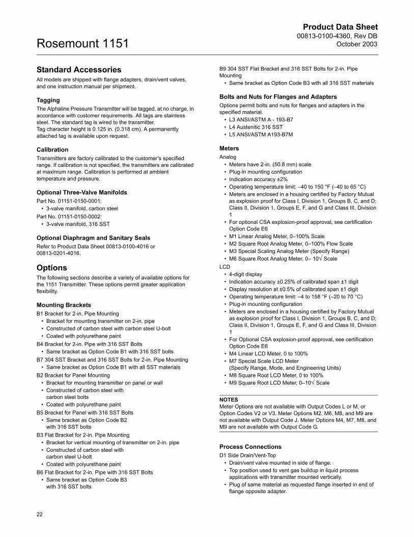
Standard Accessories All models are shipped with flange adapters, drain/vent valves, and one instruction manual per shipment.
Tagging The Alphaline Pressure Transmitter will be tagged, at no charge, in accordance with customer requirements. All tags are stainless steel. The standard tag is wired to the transmitter. Tag character height is 0.125 in. (0.318 cm). A permanently attached tag is available upon request.
Calibration Transmitters are factory calibrated to the customer�s specified range. If calibration is not specified, the transmitters are calibrated at maximum range. Calibration is performed at ambient temperature and pressure.
Optional Three-Valve Manifolds Part No. 01151-0150-0001:
� 3-valve manifold, carbon steel Part No. 01151-0150-0002:
� 3-valve manifold, 316 SST
Optional Diaphragm and Sanitary SealsRefer to Product Data Sheet 00813-0100-4016 or 00813-0201-4016.
OptionsThe following sections describe a variety of available options for the 1151 Transmitter. These options permit greater application flexibility.
Mounting BracketsB1 Bracket for 2-in. Pipe Mounting
� Bracket for mounting transmitter on 2-in. pipe� Constructed of carbon steel with carbon steel U-bolt� Coated with polyurethane paint
B4 Bracket for 2-in. Pipe with 316 SST Bolts� Same bracket as Option Code B1 with 316 SST bolts
B7 304 SST Bracket and 316 SST Bolts for 2-in. Pipe Mounting� Same bracket as Option Code B1 with all SST materials
B2 Bracket for Panel Mounting� Bracket for mounting transmitter on panel or wall� Constructed of carbon steel with
carbon steel bolts� Coated with polyurethane paint
B5 Bracket for Panel with 316 SST Bolts� Same bracket as Option Code B2
with 316 SST boltsB3 Flat Bracket for 2-in. Pipe Mounting
� Bracket for vertical mounting of transmitter on 2-in. pipe� Constructed of carbon steel with
carbon steel U-bolt� Coated with polyurethane paint
B6 Flat Bracket for 2-in. Pipe with 316 SST Bolts� Same bracket as Option Code B3
with 316 SST bolts
B9 304 SST Flat Bracket and 316 SST Bolts for 2-in. Pipe Mounting
� Same bracket as Option Code B3 with all 316 SST materials
Bolts and Nuts for Flanges and AdaptersOptions permit bolts and nuts for flanges and adapters in the specified material.
� L3 ANSI/ASTM A - 193-B7� L4 Austenitic 316 SST� L5 ANSI/ASTM A193-B7M
MetersAnalog
� Meters have 2-in. (50.8 mm) scale� Plug-in mounting configuration� Indication accuracy ±2%� Operating temperature limit: �40 to 150 °F (�40 to 65 °C)� Meters are enclosed in a housing certified by Factory Mutual
as explosion proof for Class I, Division 1, Groups B, C, and D; Class II, Division 1, Groups E, F, and G and Class III, Division 1
� For optional CSA explosion-proof approval, see certification Option Code E6
� M1 Linear Analog Meter, 0�100% Scale� M2 Square Root Analog Meter, 0�100% Flow Scale� M3 Special Scaling Analog Meter (Specify Range) � M6 Square Root Analog Meter, 0� 10√ Scale
LCD� 4-digit display� Indication accuracy ±0.25% of calibrated span ±1 digit� Display resolution at ±0.5% of calibrated span ±1 digit� Operating temperature limit: �4 to 158 °F (�20 to 70 °C)� Plug-in mounting configuration� Meters are enclosed in a housing certified by Factory Mutual
as explosion proof for Class I, Division 1, Groups B, C, and D; Class II, Division 1, Groups E, F, and G and Class III, Division 1
� For Optional CSA explosion-proof approval, see certification Option Code E6
� M4 Linear LCD Meter, 0 to 100%� M7 Special Scale LCD Meter
(Specify Range, Mode, and Engineering Units)� M8 Square Root LCD Meter, 0 to 100%� M9 Square Root LCD Meter, 0�10√ Scale
NOTESMeter Options are not available with Output Codes L or M, or Option Codes V2 or V3. Meter Options M2, M6, M8, and M9 are not available with Output Code J. Meter Options M4, M7, M8, and M9 are not available with Output Code G.
Process ConnectionsD1 Side Drain/Vent-Top
� Drain/vent valve mounted in side of flange.� Top position used to vent gas buildup in liquid process
applications with transmitter mounted vertically.� Plug of same material as requested flange inserted in end of
flange opposite adapter.
Product Data Sheet00813-0100-4360, Rev DBOctober 2003
23
Rosemount 1151
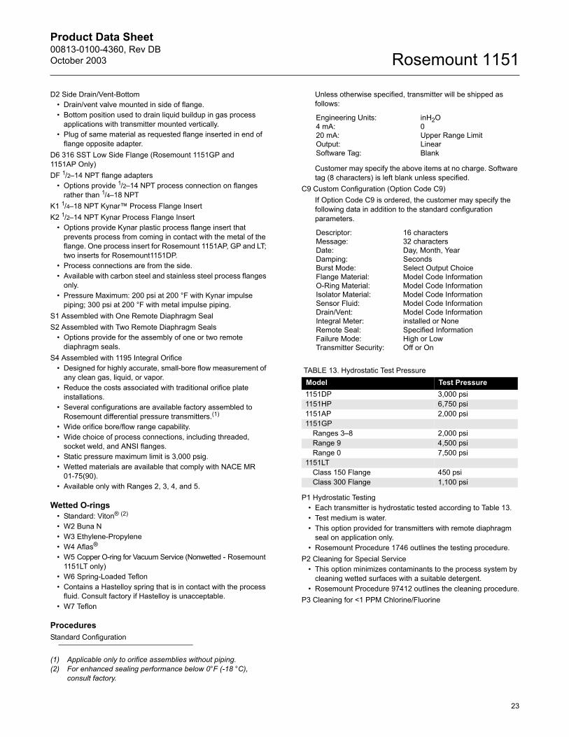
D2 Side Drain/Vent-Bottom� Drain/vent valve mounted in side of flange.� Bottom position used to drain liquid buildup in gas process
applications with transmitter mounted vertically.� Plug of same material as requested flange inserted in end of
flange opposite adapter.D6 316 SST Low Side Flange (Rosemount 1151GP and 1151AP Only)DF 1/2�14 NPT flange adapters
� Options provide 1/2�14 NPT process connection on flanges rather than 1/4�18 NPT
K1 1/4�18 NPT Kynar� Process Flange InsertK2 1/2�14 NPT Kynar Process Flange Insert
� Options provide Kynar plastic process flange insert that prevents process from coming in contact with the metal of the flange. One process insert for Rosemount 1151AP, GP and LT; two inserts for Rosemount1151DP.
� Process connections are from the side.� Available with carbon steel and stainless steel process flanges
only.� Pressure Maximum: 200 psi at 200 °F with Kynar impulse
piping; 300 psi at 200 °F with metal impulse piping.S1 Assembled with One Remote Diaphragm SealS2 Assembled with Two Remote Diaphragm Seals
� Options provide for the assembly of one or two remote diaphragm seals.
S4 Assembled with 1195 Integral Orifice� Designed for highly accurate, small-bore flow measurement of
any clean gas, liquid, or vapor.� Reduce the costs associated with traditional orifice plate
installations.� Several configurations are available factory assembled to
Rosemount differential pressure transmitters.(1)
� Wide orifice bore/flow range capability.� Wide choice of process connections, including threaded,
socket weld, and ANSI flanges.� Static pressure maximum limit is 3,000 psig.� Wetted materials are available that comply with NACE MR
01-75(90).� Available only with Ranges 2, 3, 4, and 5.
Wetted O-rings� Standard: Viton® (2)
� W2 Buna N� W3 Ethylene-Propylene� W4 Aflas®
� W5 Copper O-ring for Vacuum Service (Nonwetted - Rosemount 1151LT only)
� W6 Spring-Loaded Teflon� Contains a Hastelloy spring that is in contact with the process
fluid. Consult factory if Hastelloy is unacceptable.� W7 Teflon
ProceduresStandard Configuration
Unless otherwise specified, transmitter will be shipped as follows:
Customer may specify the above items at no charge. Software tag (8 characters) is left blank unless specified.
C9 Custom Configuration (Option Code C9)If Option Code C9 is ordered, the customer may specify the following data in addition to the standard configuration parameters.
P1 Hydrostatic Testing� Each transmitter is hydrostatic tested according to Table 13.� Test medium is water.� This option provided for transmitters with remote diaphragm
seal on application only.� Rosemount Procedure 1746 outlines the testing procedure.
P2 Cleaning for Special Service� This option minimizes contaminants to the process system by
cleaning wetted surfaces with a suitable detergent.� Rosemount Procedure 97412 outlines the cleaning procedure.
P3 Cleaning for <1 PPM Chlorine/Fluorine
(1) Applicable only to orifice assemblies without piping.(2) For enhanced sealing performance below 0°F (-18 °C),
consult factory.
Engineering Units: inH2O4 mA: 020 mA: Upper Range LimitOutput: LinearSoftware Tag: Blank
Descriptor: 16 charactersMessage: 32 charactersDate: Day, Month, YearDamping: SecondsBurst Mode: Select Output ChoiceFlange Material: Model Code InformationO-Ring Material: Model Code InformationIsolator Material: Model Code InformationSensor Fluid: Model Code InformationDrain/Vent: Model Code InformationIntegral Meter: installed or NoneRemote Seal: Specified InformationFailure Mode: High or LowTransmitter Security: Off or On
TABLE 13. Hydrostatic Test PressureModel Test Pressure1151DP 3,000 psi1151HP 6,750 psi1151AP 2,000 psi1151GP
Ranges 3�8 2,000 psiRange 9 4,500 psiRange 0 7,500 psi
1151LTClass 150 Flange 450 psiClass 300 Flange 1,100 psi

Product Data Sheet00813-0100-4360, Rev DBOctober 2003 Rosemount 1151
© 2003 Rosemount Inc. All rights reserved.
¢00813-0100-4360@¤
Rosemount, the Rosemount logotype are registered trademarks of Rosemount Inc. HART is a registered trademark of the HART Communication Foundation. δ-Cell is a trademark of Rosemount Inc. Fluorolube is a registered trademark of Hooker Chemical Co.Hastelloy, Hastelloy C, and Hastelloy C-276 are registered trademarks of Cabot Corp. Viton is a registered trademark of E.I. du Pont de Nemours & Co. Neobee M-20 is a registered trademark of Stepan Chemical Co. Syltherm and D.C. are registered trademarks of Dow Corning Corp. Teflon is a registered trademark of E.I. du Pont de Nemours & Co. Aflas is a registered trademark of Asahi Glass Co., Ltd.Kynar is a trademark of Pennwalt Inc..Emerson Process Management
Fisher-Rosemount GmbH & Co.Argelsrieder Feld 382234 WesslingGermanyTel 49 (8153) 9390Fax 49 (8153) 939172
Emerson Process Management Asia Pacific Private Limited1 Pandan CrescentSingapore 128461T (665) 6777 8211F (665) 6777 [email protected]
Rosemount Inc.8200 Market BoulevardChanhassen, MN 55317 USAT (U.S.) 1 800 999 9307T (International) (952) 906 8888F (952) 949 7001
www.rosemount.com
Beijing Rosemount Far EastInstrument Co., LimitedNo. 6 North Street, Hepingli, Dong Cheng DistrictBeijing 100013, ChinaT (86) (10) 6428 2233F (86) (10) 6422 8586
P4 Calibration at Line Pressure� This option allows transmitters to be calibrated at an elevated
line pressure rather than atmospheric pressure.� Customer must specify line pressure at which transmitter is to
be calibrated.� Customer is provided with calibration data at line pressure by
ordering Q48 certificate.� Available with Rosemount 151DP and 1151HP only. (Not
available with Remote Seals.)� Elevated line pressure and differential span desired for
calibration must not exceed the rated pressure for transmitter model.
� Minimum differential span that can be calibrated at elevated line pressure is 30 inH2O; maximum is 300 psi.
� Rosemount Procedure 3787 outlines the calibration procedure.
P5 Calibration at Temperature� This option allows transmitters to be calibrated at
temperatures other than room temperature in the range of 0 to 200 °F (�18 to 93 °C).
� Customer must specify temperature at which transmitter is to be calibrated and calibration range.
� Calibration temperature will be printed on instrument tag specified by customer, or on a tag wired to the transmitter if no tag is specified.
� Rosemount Procedure 27823B outlines the calibration procedure.
P8 0.1% Accuracy � Available on Rosemount 1151DP (Ranges 3�8), GP (Ranges
3�8), HP, and LT transmitters with 316 SST diaphragms and Output Codes E, G, L, and M. Also available on 1151DP (Range 9�0) and 1151GP (Range 9�0) with Output Code S (Min. Span = URL/10).
P7 Enhanced Temperature Performance for Analog Electronics� Transmitter is specifically compensated as a complete
assembly and will exhibit 1/2 of the standard temperature coefficient over the ambient temperature range of 20 to 140 °F (�7 to 60 °C). Outside this range, the unit will meet the standard temperature effect specification published for transmitter model.
� Not available on Range 10, limited to 1,500 psi on Range 9.� The transmitter is compensated as an assembly; therefore,
units in which the sensor module or electronics are changed after the P7 procedure has been performed will meet the standard published temperature specification for that particular model.
� Available on DP, GP, and HP models, Ranges 3�8, with SST diaphragms and Output Codes E, G, L, and M.
OutputsV1 Reverse Output
� This option permits reversing of pressure input so that electrical output will increase as pressure input decreases.
� This option applies only to Rosemount 1151GP and 1151LT. When this option is selected, the process flange, adapter, drain/vent valve, appropriate O-rings, and bolting are installed on low side of transmitter. Not available for Ranges 9 and 0.
� Not available with 1151AP. Reverse output on Rosemount 1151DP and 1151HP can be obtained by connecting high-pressure input to low side of transmitter and vice versa.
� This option should not be ordered with smart transmitters (Output Code S). The 1151 Smart transmitter can be configured for reverse output through a HART-Compatible Interface.
V2 1 � Test Resistor� A 1 � precision resistor is mounted across the test terminals
to provide 4�20 mV output or a 10�50 mV output if 10�50 mA output is used.
� This option cannot be used with any meter options or Option Codes I5 or I6.
V3 5 � Test Resistor� A 5 � precision resistor is mounted across test terminals to
provide 20�100 mV output or a 50�250 mV output if 10�50 mA output is used.
� This option cannot be used with any meter options or Option Codes I5 or I6.