
Alphaline Temperature Transmitters - Electrical Solutions...
12
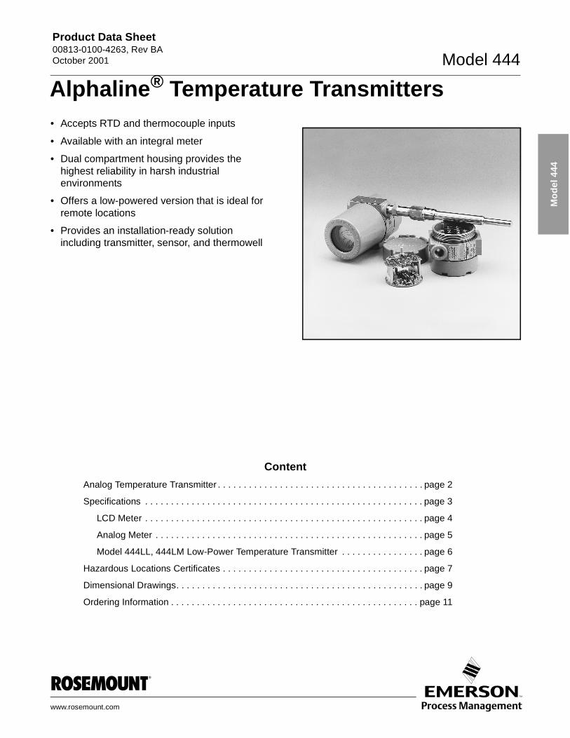
Product Data Sheet 00813-0100-4263, Rev BA October 2001 Model 444 www.rosemount.com Model 444 • Accepts RTD and thermocouple inputs • Available with an integral meter • Dual compartment housing provides the highest reliability in harsh industrial environments • Offers a low-powered version that is ideal for remote locations • Provides an installation-ready solution including transmitter, sensor, and thermowell Content Analog Temperature Transmitter . . . . . . . . . . . . . . . . . . . . . . . . . . . . . . . . . . . . . . . . page 2 Specifications . . . . . . . . . . . . . . . . . . . . . . . . . . . . . . . . . . . . . . . . . . . . . . . . . . . . . . page 3 LCD Meter . . . . . . . . . . . . . . . . . . . . . . . . . . . . . . . . . . . . . . . . . . . . . . . . . . . . . . page 4 Analog Meter . . . . . . . . . . . . . . . . . . . . . . . . . . . . . . . . . . . . . . . . . . . . . . . . . . . . page 5 Model 444LL, 444LM Low-Power Temperature Transmitter . . . . . . . . . . . . . . . . page 6 Hazardous Locations Certificates . . . . . . . . . . . . . . . . . . . . . . . . . . . . . . . . . . . . . . . page 7 Dimensional Drawings. . . . . . . . . . . . . . . . . . . . . . . . . . . . . . . . . . . . . . . . . . . . . . . . page 9 Ordering Information . . . . . . . . . . . . . . . . . . . . . . . . . . . . . . . . . . . . . . . . . . . . . . . . page 11 Alphaline ® Temperature Transmitters
Transcript of Alphaline Temperature Transmitters - Electrical Solutions...
Product Data Sheet00813-0100-4263, Rev BAOctober 2001 Model 444
Mo
del
444
Alphaline® Temperature Transmitters
• Accepts RTD and thermocouple inputs• Available with an integral meter
• Dual compartment housing provides the highest reliability in harsh industrial environments
• Offers a low-powered version that is ideal for remote locations
• Provides an installation-ready solution including transmitter, sensor, and thermowell
www.ro
Content
Analog Temperature Transmitter . . . . . . . . . . . . . . . . . . . . . . . . . . . . . . . . . . . . . . . . page 2
Specifications . . . . . . . . . . . . . . . . . . . . . . . . . . . . . . . . . . . . . . . . . . . . . . . . . . . . . . page 3
LCD Meter . . . . . . . . . . . . . . . . . . . . . . . . . . . . . . . . . . . . . . . . . . . . . . . . . . . . . . page 4
Analog Meter . . . . . . . . . . . . . . . . . . . . . . . . . . . . . . . . . . . . . . . . . . . . . . . . . . . . page 5
Model 444LL, 444LM Low-Power Temperature Transmitter . . . . . . . . . . . . . . . . page 6
Hazardous Locations Certificates . . . . . . . . . . . . . . . . . . . . . . . . . . . . . . . . . . . . . . . page 7
Dimensional Drawings. . . . . . . . . . . . . . . . . . . . . . . . . . . . . . . . . . . . . . . . . . . . . . . . page 9
Ordering Information . . . . . . . . . . . . . . . . . . . . . . . . . . . . . . . . . . . . . . . . . . . . . . . . page 11
semount.com
Product Data Sheet00813-0100-4263, Rev AA
October 2001Model 444
Mo
del
444
Analog Temperature Transmitter
The Model 444 Alphaline® Temperature Transmitter is an integral part of the Rosemount® family of temperature transmitters. The Model 444 is field-mountable and is capable of withstanding the harshest process environments. It has continuous span and zero field adjustability and removable and interchangeable plug-in circuit boards.
INTEGRAL METER
Analog or LCD integral display is available that provides local indication of temperature measurement.
SUPERIOR HOUSING DESIGN
Designed with dual-compartment housing that provides the highest reliability in harsh environments. The dual-compartment housing provides isolation between the electronics and the zero and span adjustments, the sensor terminals, and the signal wiring terminals.
FLEXIBLE INPUTS
Available for RTD and thermocouple inputs
LOW-POWER FEATURE
The Model 444LL and 444LM are low-powered that are compatible with solar or battery powered systems. The substantial reduction in power consumption makes it an ideal choice for remote locations.
INSTALLATION READY
The complete temperature measurement assembly includes the transmitter, sensor, extension, and thermowell (calibrated, wired, and configured). Upon delivery, it can be installed immediately into the process.
Rosemount Temperature Solutions
Model 3144P Temperature TransmitterField mount style available with HART® protocol.
Model 3244MV Temperature TransmitterField mount style available with FOUNDATION™ fieldbus and Profibus-PA protocols.
Model 644 Smart Temperature TransmitterHead or rail mount styles available with HART protocol.
Model 848T Eight Input Temperature TransmitterEight input transmitter available with FOUNDATION fieldbus protocol.
Model 244E Temperature TransmittersHead or rail mount styles that are PC-programmable.
Model 144H Temperature TransmittersPC-programmable head mount style for 2- and 3-wire RTD sensor inputs.
Rosemount sensors, thermowells, and extensions
Rosemount has a broad offering of RTD and thermocouples that are designed to meet plant requirements.
Temperature-2
Product Data Sheet00813-0100-4263, Rev BAOctober 2001 Model 444
Mo
del
444
Specifications
TRANSMITTER
Functional
InputsModels 444RL, LL, and LM
• 100 � R0 platinum RTD per IEC 751 Class B.
Model 444T
• Thermocouple types J and K (grounded or ungrounded) per National Institute of Standards and Technology (NIST).
Spans
OutputsLinear with temperature for RTD inputs. Linear with millivolt input signal for thermocouple inputs.
NOTEThe 4–20 mA output is not linear with temperature when the thermocouple’s millivolt input signal is not linear with temperature.
IsolationThermocouple and millivolt models input/output isolated to 500 V dc.
Span and ZeroContinuously adjustable, as defined in the ordering table. Adjustments are accessible from the terminal side of the transmitter housing.
Turn-on Time • 2 seconds
• No warm-up required
Power Supply
Approximate Output Limits
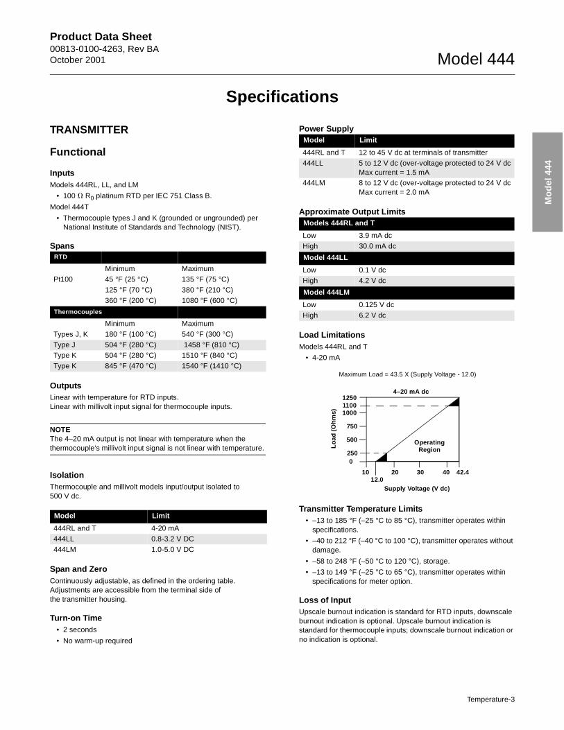
Load LimitationsModels 444RL and T
• 4-20 mA
Transmitter Temperature Limits• –13 to 185 °F (–25 °C to 85 °C), transmitter operates within
specifications.
• –40 to 212 °F (–40 °C to 100 °C), transmitter operates without damage.
• –58 to 248 °F (–50 °C to 120 °C), storage.
• –13 to 149 °F (–25 °C to 65 °C), transmitter operates within specifications for meter option.
Loss of InputUpscale burnout indication is standard for RTD inputs, downscale burnout indication is optional. Upscale burnout indication is standard for thermocouple inputs; downscale burnout indication or no indication is optional.
RTD
Minimum Maximum
Pt100 45 °F (25 °C) 135 °F (75 °C)
125 °F (70 °C) 380 °F (210 °C)
360 °F (200 °C) 1080 °F (600 °C)
Thermocouples
Minimum Maximum
Types J, K 180 °F (100 °C) 540 °F (300 °C)
Type J 504 °F (280 °C) 1458 °F (810 °C)Type K 504 °F (280 °C) 1510 °F (840 °C)
Type K 845 °F (470 °C) 1540 °F (1410 °C)
Model Limit
444RL and T 4-20 mA
444LL 0.8-3.2 V DC
444LM 1.0-5.0 V DC
Model Limit
444RL and T 12 to 45 V dc at terminals of transmitter
444LL 5 to 12 V dc (over-voltage protected to 24 V dcMax current = 1.5 mA
444LM 8 to 12 V dc (over-voltage protected to 24 V dcMax current = 2.0 mA
Models 444RL and T
Low 3.9 mA dc
High 30.0 mA dc
Model 444LL
Low 0.1 V dc
High 4.2 V dc
Model 444LM
Low 0.125 V dc
High 6.2 V dc
Maximum Load = 43.5 X (Supply Voltage - 12.0)
1250
1000
750
2500
1012.0
20 30 40 42.4
Supply Voltage (V dc)
Operating Region
4–20 mA dc
Lo
ad (
Oh
ms)
500
1100
Temperature-3
Product Data Sheet00813-0100-4263, Rev AA
October 2001Model 444
Mo
del
444
Performance
Accuracy±0.2% of calibrated span (or, for thermocouple ±0.02 millivolts, whichever is greater). Includes combined effects of transmitter repeatability, hysteresis, linearity (conformity instead of linearity for thermocouple input), and adjustment resolution. Does not include sensor error.
Stability±0.2% of calibrated span for 6 months.
Ambient Temperature EffectErrors shown for 50 °F (28 °C) change in ambient temperature.
Input Impedance (Thermocouple Inputs)Greater than 1 megohm with burnout resistors disconnected.
Power Supply Effect±0.01% of span per volt maximum.
Load EffectNo load effect other than the change in voltage supplied to the transmitter.
Vibration Effect±0.05% of span per g to 200 Hz in any axis for 3 g’s up to 33 Hz, 2 g’s from 33 to 70 Hz and 1 g from 70 to 200 Hz.
Mounting Position EffectNone
Physical
Materials of ConstructionElectronics Housing
• Low-copper aluminum. NEMA 4X, IP54, IP65, IP66, IP67, IP68
Housing Paint
• Polyurethane
Housing O-rings
• Buna-N
Sensor and Conduit Connections
• 1/2-inch conduit on electronics housing. Screw terminals and integral test jacks compatible with miniature banana plugs (Pomona 2944, 3690 or equal).
WeightTransmitter
• 3 lb (1.4 kg)
Transmitter with mounting bracket
• 4 lb (1.8 kg)
LCD METER(1)
Functional
ConfigurationThe sum of the 4 mA point and span must not exceed 9999. Adjustments are made using non-interactive zero and span buttons.
• 4 mA point limits: –999 to 1000.
• Span limits: 0200 to 9999.
Temperature Limits• Storage: –40 to 85 °C (–40 to 185 °F).
• Operating: –20 to 70 °C (–4 to 158 °F).
• Between –40 and –20 °C (–40 and –4 °F) loop is intact and the meter is not damaged.
Humidity Limitation• 0 to 95% non-condensing relative humidity
Update Period• 750 ms
Response TimeResponds to changes in input within a maximum of two update periods. If the filter is activated, then the display responds to the change within nine update periods.
RTD Inputs
Zero ± 0.17 °C plus
Span ± 0.22% plus
Elevation/ Suppression ± 0.083% of base temperature in °C
Thermocouple Inputs(Included the effect of cold junction)
Zero ± 1.38 °C plus
Span ± 0.28% plus
Elevation/ Suppression ±0.11% of base temperature in °C
(1) Available with Models 444RL 1, 2, and 3 only.
Temperature-4
Product Data Sheet00813-0100-4263, Rev BAOctober 2001 Model 444
Mo
del
444
Performance
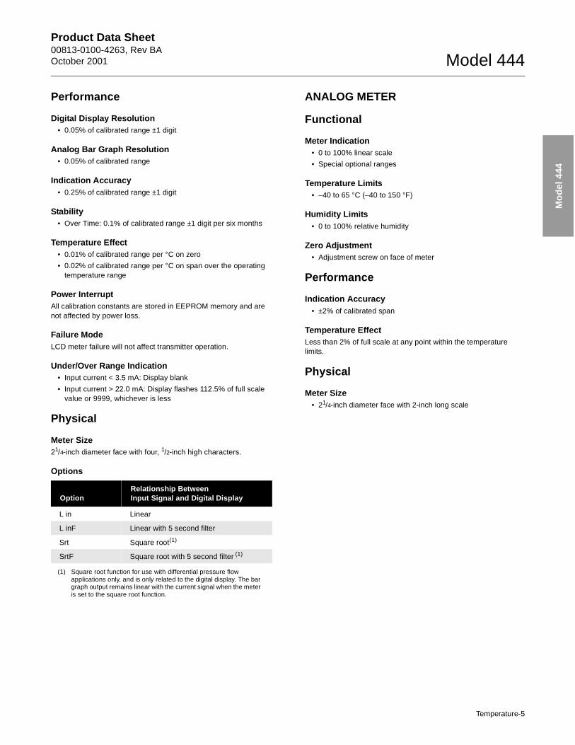
Digital Display Resolution• 0.05% of calibrated range ±1 digit
Analog Bar Graph Resolution• 0.05% of calibrated range
Indication Accuracy• 0.25% of calibrated range ±1 digit
Stability• Over Time: 0.1% of calibrated range ±1 digit per six months
Temperature Effect• 0.01% of calibrated range per °C on zero
• 0.02% of calibrated range per °C on span over the operating temperature range
Power InterruptAll calibration constants are stored in EEPROM memory and are not affected by power loss.
Failure ModeLCD meter failure will not affect transmitter operation.
Under/Over Range Indication• Input current < 3.5 mA: Display blank
• Input current > 22.0 mA: Display flashes 112.5% of full scale value or 9999, whichever is less
Physical
Meter Size21/4-inch diameter face with four, 1/2-inch high characters.
Options
ANALOG METER
Functional
Meter Indication• 0 to 100% linear scale
• Special optional ranges
Temperature Limits• –40 to 65 °C (–40 to 150 °F)
Humidity Limits• 0 to 100% relative humidity
Zero Adjustment• Adjustment screw on face of meter
Performance
Indication Accuracy• ±2% of calibrated span
Temperature EffectLess than 2% of full scale at any point within the temperature limits.
Physical
Meter Size• 21/4-inch diameter face with 2-inch long scale
OptionRelationship BetweenInput Signal and Digital Display
L in Linear
L inF Linear with 5 second filter
Srt Square root(1)
(1) Square root function for use with differential pressure flow applications only, and is only related to the digital display. The bar graph output remains linear with the current signal when the meter is set to the square root function.
SrtF Square root with 5 second filter (1)
Temperature-5
Product Data Sheet00813-0100-4263, Rev AA
October 2001Model 444
Mo
del
444
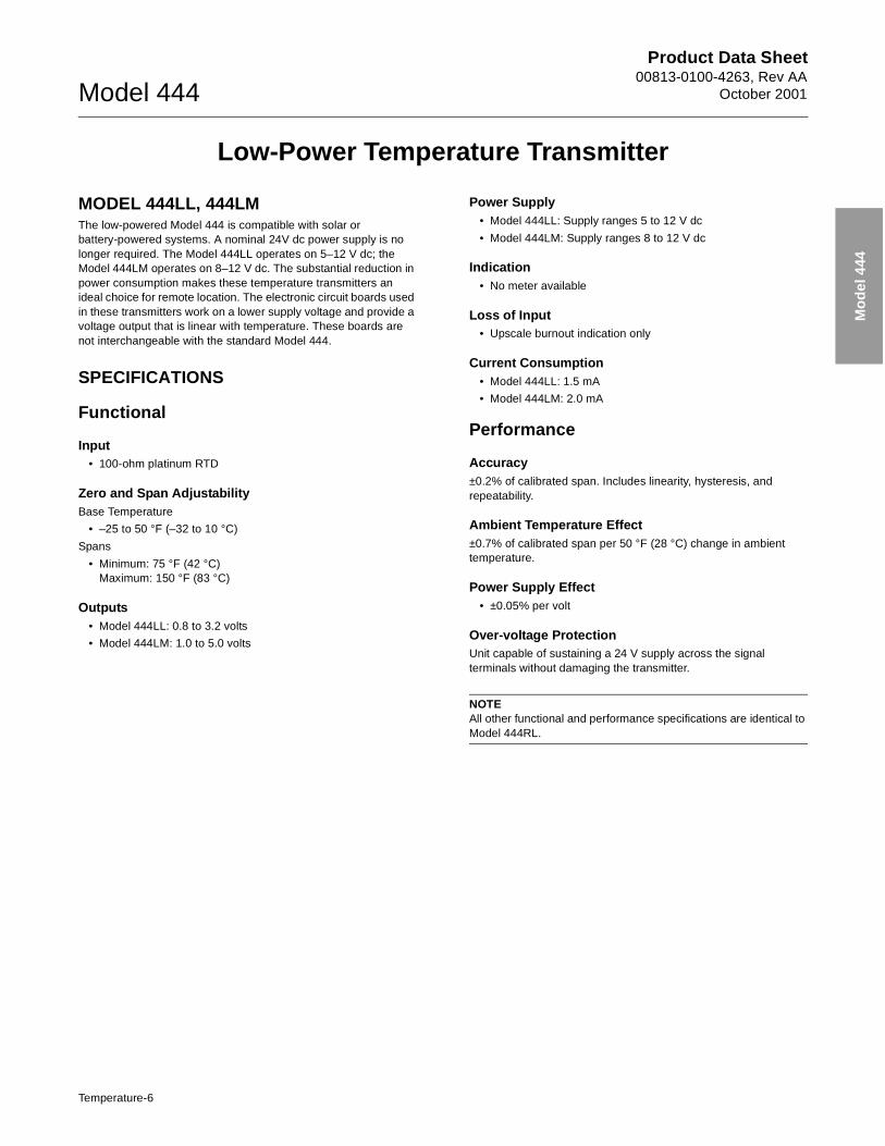
Low-Power Temperature Transmitter
MODEL 444LL, 444LM The low-powered Model 444 is compatible with solar or battery-powered systems. A nominal 24V dc power supply is no longer required. The Model 444LL operates on 5–12 V dc; the Model 444LM operates on 8–12 V dc. The substantial reduction in power consumption makes these temperature transmitters an ideal choice for remote location. The electronic circuit boards used in these transmitters work on a lower supply voltage and provide a voltage output that is linear with temperature. These boards are not interchangeable with the standard Model 444.
SPECIFICATIONS
Functional
Input• 100-ohm platinum RTD
Zero and Span AdjustabilityBase Temperature
• –25 to 50 °F (–32 to 10 °C)
Spans
• Minimum: 75 °F (42 °C)Maximum: 150 °F (83 °C)
Outputs• Model 444LL: 0.8 to 3.2 volts
• Model 444LM: 1.0 to 5.0 volts
Power Supply• Model 444LL: Supply ranges 5 to 12 V dc
• Model 444LM: Supply ranges 8 to 12 V dc
Indication• No meter available
Loss of Input• Upscale burnout indication only
Current Consumption• Model 444LL: 1.5 mA
• Model 444LM: 2.0 mA
Performance
Accuracy±0.2% of calibrated span. Includes linearity, hysteresis, and repeatability.
Ambient Temperature Effect±0.7% of calibrated span per 50 °F (28 °C) change in ambient temperature.
Power Supply Effect• ±0.05% per volt
Over-voltage ProtectionUnit capable of sustaining a 24 V supply across the signal terminals without damaging the transmitter.
NOTEAll other functional and performance specifications are identical to Model 444RL.
Temperature-6
Product Data Sheet00813-0100-4263, Rev BAOctober 2001 Model 444
Mo
del
444
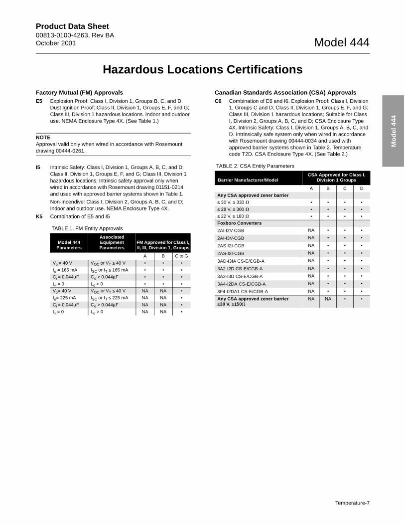
Hazardous Locations Certifications
Factory Mutual (FM) ApprovalsE5 Explosion Proof: Class I, Division 1, Groups B, C, and D.
Dust Ignition Proof: Class II, Division 1, Groups E, F, and G; Class III, Division 1 hazardous locations. Indoor and outdoor use. NEMA Enclosure Type 4X. (See Table 1.)
NOTEApproval valid only when wired in accordance with Rosemount drawing 00444-0261.
I5 Intrinsic Safety: Class I, Division 1, Groups A, B, C, and D; Class II, Division 1, Groups E, F, and G; Class III, Division 1 hazardous locations; Intrinsic safety approval only when wired in accordance with Rosemount drawing 01151-0214 and used with approved barrier systems shown in Table 1.
Non-Incendive: Class I, Division 2, Groups A, B, C, and D; Indoor and outdoor use. NEMA Enclosure Type 4X.
K5 Combination of E5 and I5
Canadian Standards Association (CSA) ApprovalsC6 Combination of E6 and I6. Explosion Proof: Class I, Division
1, Groups C and D; Class II, Division 1, Groups E, F, and G; Class III, Division 1 hazardous locations; Suitable for Class I, Division 2, Groups A, B, C, and D; CSA Enclosure Type 4X. Intrinsic Safety: Class I, Division 1, Groups A, B, C, and D. Intrinsically safe system only when wired in accordance with Rosemount drawing 00444-0034 and used with approved barrier systems shown in Table 2. Temperature code T2D. CSA Enclosure Type 4X. (See Table 2.)
TABLE 1. FM Entity Approvals
Model 444 Parameters
Associated Equipment Parameters
FM Approved for Class I, II, III, Division 1, Groups
A B C to G
Vo = 40 V VOC or VT ≤ 40 V • • •
Io = 165 mA ISC or IT ≤ 165 mA • • •
Ci = 0.044µF Co > 0.044µF • • •
Li = 0 Lo > 0 • • •
Vo= 40 V VOC or VT ≤ 40 V NA NA •
Io= 225 mA ISC or IT ≤ 225 mA NA NA •
Ci = 0.044µF Co > 0.044µF NA NA •
Li = 0 Lo > 0 NA NA •
TABLE 2. CSA Entity Parameters
Barrier Manufacturer/ModelCSA Approved for Class I,
Division 1 Groups
A B C D
Any CSA approved zener barrier
≤ 30 V, ≥ 330 � • • • •
≤ 28 V, ≥ 300 � • • • •
≤ 22 V, ≥ 180 � • • • •
Foxboro Converters
2AI-I2V-CGB NA • • •
2AI-I3V-CGB NA • • •
2AS-I2I-CGB NA • • •
2AS-I3I-CGB NA • • •
3AD-I3IA CS-E/CGB-A NA • • •
3A2-I2D CS-E/CGB-A NA • • •
3A2-I3D CS-E/CGB-A NA • • •
3A4-I2DA CS-E/CGB-A NA • • •
3F4-I2DA1 CS-E/CGB-A NA • • •
Any CSA approved zener barrier ≤30 V, ≥150�
NA NA • •
Temperature-7
Product Data Sheet00813-0100-4263, Rev AA
October 2001Model 444
Mo
del
444
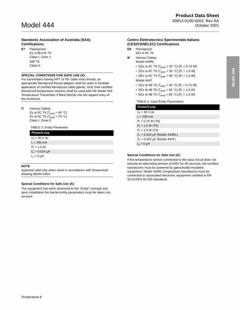
Standards Association of Australia (SAA) CertificationsE7 Flameproof:
Ex d IIB+H2 T6Class I, Zone 1.
DIP T6Class II.
SPECIAL CONDITIONS FOR SAFE USE (X):For transmitters having NPT or PG cable entry thread, an appropriate flameproof thread adaptor shall be used to facilitate application of certified flameproof cable glands. Only SAA-certified flameproof temperature sensors shall be used with the Model 444 Temperature Transmitter if fitted directly into the tapped entry of the enclosure.
I7 Intrinsic Safety: Ex ia IIC T6 (Tamb = 40 °C)Ex ia IIC T5 (Tamb = 70 °C)Class I, Zone 0.
NOTEApproval valid only when wired in accordance with Rosemount drawing 00444-0264.
Special Conditions for Safe Use (X):
The equipment has been assessed to the “Entity” concept and upon installation the barrier/entity parameters must be taken into account.
Centro Elettrotecnico Sperimentale Italiano (CESI/CENELEC) CertificationsE8 Flameproof:
EEx d IIC T6
I8 Intrinsic Safety:Model 444RL
• EEx ia IIC T6 (Tamb = 40 °C) [Pi = 0.75 W]
• EEx ia IIC T5 (Tamb = 55 °C) [Pi = 1.0 W]
• EEx ia IIC T4 (Tamb = 80 °C) [Pi = 1.0 W]
Model 444T
• EEx ib IIB T6 (Tamb = 40 °C) [Pi = 0.75 W]
• EEx ib IIB T5 (Tamb = 55 °C) [Pi = 1.0 W]
• EEx ib IIB T4 (Tamb = 80 °C) [Pi = 1.0 W]
Special Conditions for Safe Use (X):
If the temperature sensor connected to the input circuit does not tolerate an alternating tension of 500V for 60 seconds, the certified transducers must be powered by galvanically-insulated equipment. Model 444RL temperature transducers must be connected to associated electronic equipment certified to EN 50.014/EN 50.020 standards.
TABLE 3. Entity Parameter
Power/Loop
Ui = 30 V dc
Ii = 200 mA
Pi = 1.0 W
Ci = 0.024 µF
Li = 0 µH
TABLE 4. Input Entity Parameters
Power/Loop
Ui = 30 V dc
Ii = 200 mA
Pi = 0.75 W (T6)
Pi = 1.0 W (T5)
Pi = 1.0 W (T4)
Ci = 0.024 µF (Model 444RL)
Ci = 0.024 µF (Model 444T)
Li = 0 µH
Temperature-8
Product Data Sheet00813-0100-4263, Rev BAOctober 2001 Model 444
Mo
del
444
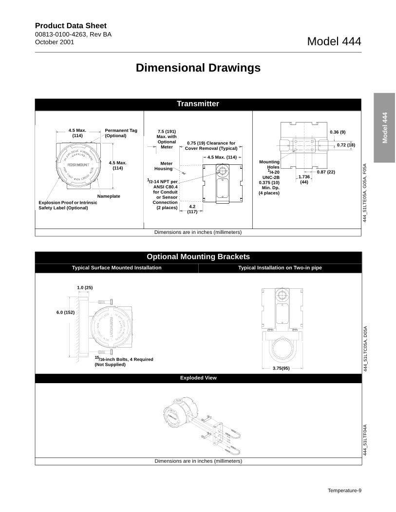
Dimensional Drawings
Transmitter
Dimensions are in inches (millimeters)
4.5 Max.(114)
Permanent Tag (Optional)
NameplateExplosion Proof or Intrinsic Safety Label (Optional)
4.5 Max.(114)
7.5 (191) Max. with Optional
Meter0.75 (19) Clearance for
Cover Removal (Typical)
4.5 Max. (114)Meter
Housing
4.2(117)
1/2-14 NPT perANSI C80.4for Conduit
or SensorConnection
(2 places)
MountingHoles1/4-20
UNC-2B0.375 (10)
Min. Dp.(4 places)
1.736(44)
0.36 (9)
0.72 (18)
0.87 (22)
444
_51
LTE
05A
, G
05A
, F
05A
Optional Mounting BracketsTypical Surface Mounted Installation Typical Installation on Two-in pipe
Exploded View
Dimensions are in inches (millimeters)
1.0 (25)
6.0 (152)
15/16-inch Bolts, 4 Required(Not Supplied)
3.75(95) 44
4_51
LT
C0
5A
, D
05A
444
_51
LTF
04A
Temperature-9
Product Data Sheet00813-0100-4263, Rev AA
October 2001Model 444
Mo
del
444
115
1_11
51B
02
C
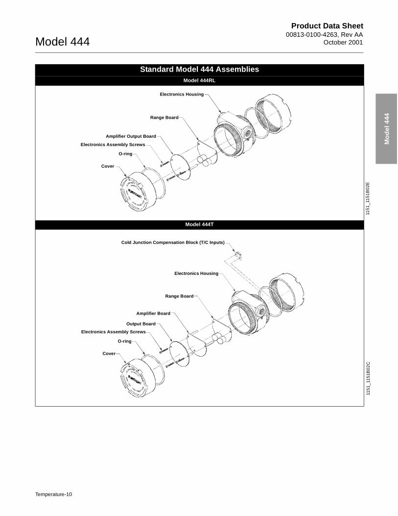
Standard Model 444 AssembliesModel 444RL
Model 444T
Cover
Amplifier Output Board
Range Board
Electronics Assembly Screws
O-ring
Electronics Housing
115
1_11
51B
02E
Cover
Amplifier Board
O-ring
Output Board
Electronics Assembly Screws
Range Board
Cold Junction Compensation Block (T/C Inputs)
Electronics Housing
Temperature-10
Product Data Sheet00813-0100-4263, Rev BAOctober 2001 Model 444
Mo
del
444
Ordering Information
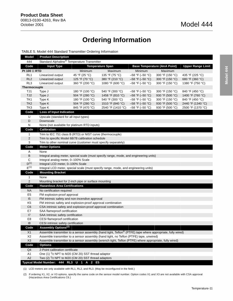
TABLE 5. Model 444 Standard Transmitter Ordering Information
Model Product Description
444 Standard Alphaline® Temperature Transmitter
Code Input Type Temperature Span Base Temperature (4mA Point) Upper Range Limit
Pt 100 � RTD Minimum Maximum Minimum MaximumRL1 Linearized output 45 °F (25 °C) 135 °F (75 °C) –58 °F (–50 °C) 300 °F (150 °C) 435 °F (225 °C)RL2 Linearized output 125 °F (70 °C) 380 °F (210 °C) –58 °F (–50 °C) 300 °F (150 °C) 680 °F (360 °C)RL3 Linearized output 360 °F (200 °C) 1080 °F (600 °C) –58 °F (–50 °C) 300 °F (150 °C) 1380 °F (750 °C)
ThermocoupleTJ1 Type J 180 °F (100 °C) 540 °F (300 °C) –58 °F (–50 °C) 300 °F (150 °C) 840 °F (450 °C)TJ2 Type J 504 °F (280 °C) 1458 °F (810 °C) –58 °F (–50 °C) 930 °F (500 °C) 1400 °F (760 °C)TK1 Type K 180 °F (100 °C) 540 °F (300 °C) –58 °F (–50 °C) 300 °F (150 °C) 840 °F (450 °C)TK2 Type K 504 °F (280 °C) 1510 °F (840 °C) –58 °F (–50 °C) 930 °F (500 °C) 2440 °F (1340 °C)TK3 Type K 845 °F (470 °C) 2540 °F (1410 °C) –58 °F (–50 °C) 930 °F (500 °C) 2500 °F (1370 °C)
Code Loss of Input Indication
U Upscale (standard for all input types)D DownscaleN None (not available for platinum RTD inputs)
Code Calibration
1 Trim to IEC 751 class B (RTD) or NIST curve (thermocouple)2 Trim to specific Model 68/78 calibration schedule3 Trim to other nominal curve (customer must specify separately)
Code Meter Options
A NoneB Integral analog meter, special scale (must specify range, mode, and engineering units)C Integral analog meter, 0–100% Scale
D(1)
(1) LCD meters are only available with RL1, RL2, and RL3. (May be reconfigured in the field.)
Integral LCD meter, 0–100% ScaleE(1) Integral LCD meter, special scale (must specify range, mode, and engineering units)
Code Mounting Bracket
1 None2 Mounting bracket for 2-inch pipe or surface mounting
Code Hazardous Area Certifications
NA No certification requiredE5 FM explosion-proof approvalI5 FM intrinsic safety and non-incendive approvalK5 FM intrinsic safety and explosion-proof approval combinationC6 CSA intrinsic safety and explosion-proof approval combination E7 SAA flameproof certificationI7 SAA Intrinsic safety certificationE8 CESI flameproof certificationI8 CESI intrinsic safety certification
Code Assembly Options(2)
(2) If ordering X1, X2, or X3 options, specify the same code on the sensor model number. Option codes X1 and X3 are not available with CSA approval (Hazardous Area Certifications C6.)
X1 Assemble transmitter to a sensor assembly (hand tight, Teflon® (PTFE) tape where appropriate, fully wired)X2 Assemble transmitter to a sensor assembly (hand tight, no Teflon (PTFE) tape, unwired)X3 Assemble transmitter to a sensor assembly (wrench tight, Teflon (PTFE) where appropriate, fully wired)
Code Options
Q4 2-Point calibration certificateA1 One (1) 1/2 NPT to M20 (CM 20) SST thread adaptorA2 Two (2) 1/2 NPT to M20 (CM 20) SST thread adaptors
Typical Model Number: 444 RL3 U 1 A 2 E5
Temperature-11
Product Data Sheet00813-0100-4263, Rev BAOctober 2001 Model 444
Mo
del
444
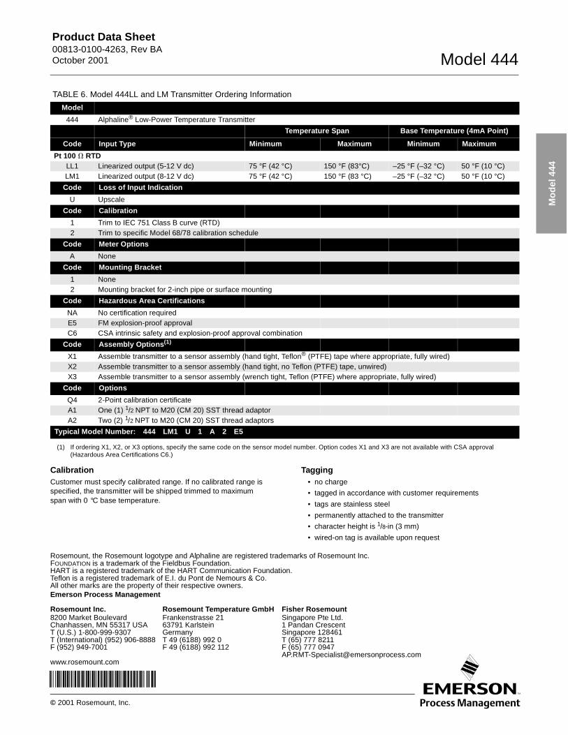
CalibrationCustomer must specify calibrated range. If no calibrated range is specified, the transmitter will be shipped trimmed to maximum span with 0 °C base temperature.
Tagging• no charge
• tagged in accordance with customer requirements
• tags are stainless steel
• permanently attached to the transmitter
• character height is 1/8-in (3 mm)
• wired-on tag is available upon request
TABLE 6. Model 444LL and LM Transmitter Ordering Information
Model TABLE 7. Product Description
444 Alphaline® Low-Power Temperature Transmitter
Temperature Span Base Temperature (4mA Point)
Code Input Type Minimum Maximum Minimum Maximum
Pt 100 � RTD LL1 Linearized output (5-12 V dc) 75 °F (42 °C) 150 °F (83°C) –25 °F (–32 °C) 50 °F (10 °C)LM1 Linearized output (8-12 V dc) 75 °F (42 °C) 150 °F (83 °C) –25 °F (–32 °C) 50 °F (10 °C)
Code Loss of Input Indication
U Upscale
Code Calibration
1 Trim to IEC 751 Class B curve (RTD)2 Trim to specific Model 68/78 calibration schedule
Code Meter Options
A None
Code Mounting Bracket
1 None2 Mounting bracket for 2-inch pipe or surface mounting
Code Hazardous Area Certifications
NA No certification requiredE5 FM explosion-proof approvalC6 CSA intrinsic safety and explosion-proof approval combination
Code Assembly Options(1)
X1 Assemble transmitter to a sensor assembly (hand tight, Teflon® (PTFE) tape where appropriate, fully wired)X2 Assemble transmitter to a sensor assembly (hand tight, no Teflon (PTFE) tape, unwired)X3 Assemble transmitter to a sensor assembly (wrench tight, Teflon (PTFE) where appropriate, fully wired)
Code Options
Q4 2-Point calibration certificateA1 One (1) 1/2 NPT to M20 (CM 20) SST thread adaptorA2 Two (2) 1/2 NPT to M20 (CM 20) SST thread adaptors
Typical Model Number: 444 LM1 U 1 A 2 E5
(1) If ordering X1, X2, or X3 options, specify the same code on the sensor model number. Option codes X1 and X3 are not available with CSA approval (Hazardous Area Certifications C6.)
Emerson Process Management
© 2001 Rosemount, Inc.
Rosemount, the Rosemount logotype and Alphaline are registered trademarks of Rosemount Inc.FOUNDATION is a trademark of the Fieldbus Foundation.HART is a registered trademark of the HART Communication Foundation.Teflon is a registered trademark of E.I. du Pont de Nemours & Co.All other marks are the property of their respective owners.
¢00813-0100-4263`¤
Rosemount Temperature GmbHFrankenstrasse 2163791 KarlsteinGermanyT 49 (6188) 992 0F 49 (6188) 992 112
Fisher RosemountSingapore Pte Ltd.1 Pandan CrescentSingapore 128461T (65) 777 8211F (65) 777 [email protected]
Rosemount Inc.8200 Market BoulevardChanhassen, MN 55317 USAT (U.S.) 1-800-999-9307T (International) (952) 906-8888F (952) 949-7001
www.rosemount.com