Product Data - dms.hvacpartners.comdms.hvacpartners.com/docs/1009/Public/03/50JX-4PD.pdf · indoor...
26
50JX 3-PHASE SINGLE-PACKAGED HEAT PUMP UNITS 2-1/2 to 5 Nominal Tons Product Data Single-Package Heat Pump for Residential and Light Commercial Applications • Low Sound Levels • 12 SEER Features/Benefits One-piece heat pump with optional electric heater, low installation cost, dependable performance and easy maintenance. Efficient operation The 50JX is designed to deliver SEERs (Seasonal Energy Efficiency Ratios) of 12.0 and HSPFs (Heating Seasonal Performance Factors) of up to 7.2 Easy Installation Factory-assembled package is a compact, fully self-contained, heat pump unit that is pre-wired, pre-piped, and pre-charged for minimum installation expense. 50JX units are available in a variety of standard capacity ranges with voltage options to meet residential and light commercial requirements. Units install easily on a rooftop or at ground-level. Durable, dependable components Scroll Compressors are hermetically sealed against contamination to help promote long life and dependable operation. Vibration isolation provides quiet operation. Compressors have internal high-pressure and overcurrent protection. Direct-drive multi-speed, PSC (permanent split capacitor) blower motor is standard on all 50JX models. Direct-drive, PSC condenser-fan motors are designed to help reduce energy consumption and provide for cooling operation down to 40°F outdoor temperature. Motormaster® II low ambient kit is available as a field- installed accessory and does not require a special motor. UNIT 50JX (STANDARD)
Transcript of Product Data - dms.hvacpartners.comdms.hvacpartners.com/docs/1009/Public/03/50JX-4PD.pdf · indoor...

50JX3-PHASE SINGLE-PACKAGED HEAT PUMP UNITS2-1/2 to 5 Nominal Tons
Product Data
Single-Package Heat Pump for Residential and Light Commercial Applications• Low Sound Levels• 12 SEER
Features/Benefits
One-piece heat pump with optional electric heater, low installation cost, dependable performance and easy maintenance.
Efficient operation
The 50JX
is designed to deliver SEERs (Seasonal Energy Efficiency Ratios) of 12.0 and HSPFs (Heating Seasonal Performance Factors) of up to 7.2
Easy Installation
Factory-assembled package
is a compact, fully self-contained, heat pump unit that is pre-wired, pre-piped, and pre-charged for minimum installation expense. 50JX units are available in a variety of standard capacity ranges with voltage options to meet residential and light commercial requirements. Units install easily on a rooftop or at ground-level.
Durable, dependable components
Scroll Compressors
are hermetically sealed against contamination to help promote long life and dependable operation. Vibration isolation provides quiet operation. Compressors have internal high-pressure and overcurrent protection.
Direct-drive multi-speed, PSC (permanent split capacitor) blower motor
is standard on all 50JX models.
Direct-drive, PSC condenser-fan motors
are designed to help reduce energy consumption and provide for cooling operation down to 40°F outdoor temperature. Motormaster® II low ambient kit is available as a field-installed accessory and does not require a special motor.
UNIT 50JX(STANDARD)
2
50JX
Corporate thermostats
work with Carrier’s small packaged products as a system to promote year round comfort.
Refrigerant system
is designed to provide dependability. Liquid refrigerant strainers are used to promote clean, unrestricted operation. Each unit leaves the factory with a full refrigerant charge. Refrigerant service connections make checking operating pressures easier.
Low Pressure/Loss of Charge Switch
assures added safety and reliability for the compressor.
Indoor and outdoor coils
are computer-designed for optimum heat transfer and cooling efficiency. The indoor coil is fabricated from copper tube and aluminum fins and is located inside the unit for protection against damage. The outdoor coil is internally mounted on the top tier of the unit. A FIOP (Factory-Installed Option) metal louvered grille is available on all models. Copper fin coils and pre-coated fin coils are available from the factory by special order. These coils are recommended in applications where aluminum fins are likely to be damaged
due to corrosion. They are ideal for seacoast applications.
Low sound ratings
ensure a quiet indoor and outdoor environment with sound ratings as low as 72 dB.(See page 3.)
Easy to service cabinets
provide easy single-panel accessibility to serviceable components during maintenance and installation. The unit base with integrated drain provides easy ground level installation with or without a mounting pad. Convenient handholds are provided to manipulate the unit on the jobsite. A nesting feature ensures a positive unit base to roof curb seal when the unit is roof mounted. A convenient 3/4-in. wide perimeter flange makes frame mounting on a rooftop easy.
Downflow operation
is easily provided in the field to allow vertical ductwork connections. The unit base utilizes knockout style seals on the bottom openings to ensure a positive seal in the horizontal airflow mode.
Standard metal duct covers
with insulation come with the unit and cover
the duct openings. These can be left in place if the units are converted to downshot.
Cabinets
are constructed of heavy-duty, phosphated, zinc-coated prepainted steel capable of withstanding 500 hours of salt spray. Interior surfaces are insulated with cleanable semi-rigid insulation board, which keeps the conditioned air from being affected by the outdoor ambient temperature and provides improved indoor air quality. (Conforms to American Society of Heating, Refrigeration and Air Conditioning Engineers No. 62P.) The sloped drain minimizes standing water in the drain, which is provided with an external drain fitting.
Short-Cycling protection
for the compressor is incorporated into our defrost control board ensuring a five minute delay (+/-2 minutes) before restarting compressor after shutdown for any reason.
Table of contents
PageFeatures/Benefits . . . . . . . . . . . . . . . . . . . . . . . . . . . . . . . . . . . . . . . . . . . . . . . . . . . . . . . . . . . . . . . . . . . . . . . . . . . . . . . . . . . . . . . .1,2Model Number Nomenclature . . . . . . . . . . . . . . . . . . . . . . . . . . . . . . . . . . . . . . . . . . . . . . . . . . . . . . . . . . . . . . . . . . . . . . . . . . . . . . . 3ARI Capacities . . . . . . . . . . . . . . . . . . . . . . . . . . . . . . . . . . . . . . . . . . . . . . . . . . . . . . . . . . . . . . . . . . . . . . . . . . . . . . . . . . . . . . . . . . . 3Physical Data . . . . . . . . . . . . . . . . . . . . . . . . . . . . . . . . . . . . . . . . . . . . . . . . . . . . . . . . . . . . . . . . . . . . . . . . . . . . . . . . . . . . . . . . . . . . 4Options and Accessories . . . . . . . . . . . . . . . . . . . . . . . . . . . . . . . . . . . . . . . . . . . . . . . . . . . . . . . . . . . . . . . . . . . . . . . . . . . . . . . . . .5,6Base Unit Dimensions . . . . . . . . . . . . . . . . . . . . . . . . . . . . . . . . . . . . . . . . . . . . . . . . . . . . . . . . . . . . . . . . . . . . . . . . . . . . . . . . . . . .7,8Accessory Dimensions. . . . . . . . . . . . . . . . . . . . . . . . . . . . . . . . . . . . . . . . . . . . . . . . . . . . . . . . . . . . . . . . . . . . . . . . . . . . . . . . . . . . . 9Selection Procedure . . . . . . . . . . . . . . . . . . . . . . . . . . . . . . . . . . . . . . . . . . . . . . . . . . . . . . . . . . . . . . . . . . . . . . . . . . . . . . . . . . . . . . 10Performance Data. . . . . . . . . . . . . . . . . . . . . . . . . . . . . . . . . . . . . . . . . . . . . . . . . . . . . . . . . . . . . . . . . . . . . . . . . . . . . . . . . . . . . 11-17Typical Piping and Wiring. . . . . . . . . . . . . . . . . . . . . . . . . . . . . . . . . . . . . . . . . . . . . . . . . . . . . . . . . . . . . . . . . . . . . . . . . . . . . . . . . 18Application Data . . . . . . . . . . . . . . . . . . . . . . . . . . . . . . . . . . . . . . . . . . . . . . . . . . . . . . . . . . . . . . . . . . . . . . . . . . . . . . . . . . . . . . . . 19Electrical Data . . . . . . . . . . . . . . . . . . . . . . . . . . . . . . . . . . . . . . . . . . . . . . . . . . . . . . . . . . . . . . . . . . . . . . . . . . . . . . . . . . . . . . . .20,21Typical Wiring Schematics . . . . . . . . . . . . . . . . . . . . . . . . . . . . . . . . . . . . . . . . . . . . . . . . . . . . . . . . . . . . . . . . . . . . . . . . . . . . . .22,23Controls . . . . . . . . . . . . . . . . . . . . . . . . . . . . . . . . . . . . . . . . . . . . . . . . . . . . . . . . . . . . . . . . . . . . . . . . . . . . . . . . . . . . . . . . . . . . . . . 24Guide Specifications . . . . . . . . . . . . . . . . . . . . . . . . . . . . . . . . . . . . . . . . . . . . . . . . . . . . . . . . . . . . . . . . . . . . . . . . . . . . . . . . . . .25,26

3
50JX
Model number nomenclature
ARI* capacities
COOLING CAPACITIES AND EFFICIENCIES
50JX 030
Model No.
50JX – Single Packaged Heat Pump
Nominal Cooling Capacity (Tons)030
– 2-1/2
036
– 3
042
– 3-1/2
048
– 4
060
– 5
UNIT50JX
NOMINALTONS
STANDARDCFM
NET COOLINGCAPACITIES
(Btuh)SEER†
SOUNDRATINGS‡
(dB)
030 2-1/2 1000 29,000 12.0 72036 3 1200 35,000 12.0 77042 3-1/2 1400 41,500 12.0 73048 4 1450 47,000 12.0 79060 5 1750 60,000 12.0 79
LEGENDdB — Sound Levels (decibels)COP — Coefficient of PerformanceHSPF — Heating Season Performance Factordb — Dry BulbSEER — Seasonal Energy Efficiency Ratiowb — Wet Bulb
* Air Conditioning & Refrigeration Institute.† Rated in accordance with U.S. Government DOE Department of
Energy) test procedures and/or ARI Standard 210/240-94.‡ Tested in accordance with ARI Standard 270-95 (not listed in ARI).
NOTES:1. Ratings are net values, reflecting the effects of circulating fan heat.
Ratings are based on:Cooling Standard: 80°F db, 67°F wb indoor entering-air tempera-ture and 95°F db outdoor entering-air temperature.
2. Before purchasing this appliance, read important energy cost andefficiency information available from your retailer.
5 0 1 AD
Options(None)
– Wire Grille
AD
– Louvered Grille
BT
– Wire Grille and Vinyl-Coated Condenser Coil Fin
XT
– Louvered Grille and Vinyl-Coated Con-denser Coil Fin
CC
– Wire Grille, AL Evaporator and CU/CU Condenser Coil
AC
– Louvered Grille, AL Evaporator and CU/CU condenser Coil
AU
– Louvered Grille, CU/CU Evaporator and Condenser Coils
Packaging
Series
V-Ph-Hz5
– 208/230-3-60
6
– 460-3-60
TT
Options- -
– Wire Grille
AD
– Louvered Grille
BT
– Wire Grille and vinyl-coated outdoor coil fin
XT
– Louvered Grille and vinyl-coated outdoor coil fin
CC
– Wire Grille, AL indoor and CU/CU outdoor coil
CU
– Wire Grille, CU/CU indoor and outdoor coils
AC
– Louvered Grille, AL indoor and CU/CU outdoor coil
AU
– Louvered Grille, CU/CU indoor and outdoor coils
TP
– Tin-Plated Indoor Coil Hairpins (Refer to current Price Page for additional combination of options)
AL
— Aluminum
CU
— Copper
HEATING CAPACITIES AND EFFICIENCIES
UNIT50JX
HIGH HEAT CAPACITY (BTUH)@47°F
HIGH HEAT COP@47°F
LOW HEAT CAPACITY (BTUH)@17°F
LOW HEAT COP@17°F HSPF
030 28,200 3.2 15,600 2 7.1036 34,000 3.2 19,000 1.9 7.1042 40,000 3.2 22,000 2 7.2048 44,000 3.1 23,600 2 7.1060 57,000 3.2 32,000 2 7.2
4
50JX
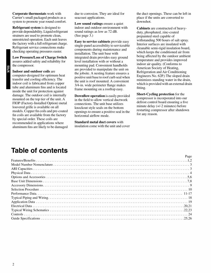
OUTDOOR SOUND: OCTAVE BAND DATA—DECIBELS
Physical data
* Air filter pressure drop for non-standard filters must not exceed 0.08 in. wg.
UNIT 50JX
Frequency (Hz) 030 036 042 048 060
63
47.2 52.9 53.9 57.5 53.0
125
54.7 57.8 58.4 67.8 64.8
250
60.0 62.4 63.1 68.9 66.5
500
66.6 69.5 66.2 71.7 70.4
1000
67.0 72.3 66.8 72.7 73.2
2000
63.7 69.0 63.6 69.2 69.6
4000
59.5 65.4 59.9 65.7 67.1
8000
52.1 57.4 54.1 58.5 60.6
UNIT SIZE 50JX 030 036 042 048 060
NOMINAL CAPACITY (ton)
2-1/2 3 3-1/2 4 5
OPERATING WEIGHT (lb)
320 328 350 375 428
COMPRESSORS Quantity (lb)
Scroll1
REFRIGERANT (R-22)Quantity (lb)
6.4 7.0 10.8 10.1 12.3
REFRIGERANT METERING DEVICEOrifice Indoor (in.)Orifice Outdoor (in.)
Accurater
OUTDOOR COILRows—Fins/in.Face Area (sq ft)
2—1710.3
2—1710.3
2—1713.7
2—1713.7
2—1715.7
OUTDOOR FANNominal CfmDiameter (in.)Motor Hp (Rpm)
235022
1/8 (825)
280022
1/4 (1100)
280022
1/8 (825)
330022
1/4 (1100)
330022
1/4 (1100)
INDOOR COILRows—Fins/in.Face Area (sq ft)
3—153.7
4—153.7
4—154.7
4—154.7
4—155.7
INDOOR BLOWERNominal Airflow (Cfm)Size (in.)Motor Hp (RPM)
100010 x 10
1/4 (1075)
120010 x 10
1/2 (1075)
140011 x 10
1/2 (1075)
145011 x 10
1/2 (1075)
175011 x 10
1.0 (1040)
RETURN-AIR FILTERS (in.)*Throwaway
20 x 20 x 1 20 x 24 x 1 24 x 30 x 1 24 x 30 x 1 24 x 30 x 1
32 5
A2
MA
NU
FAC
TUR
ER
CERTIFIED TO ARI AS COMPLY
ING
WITH
ARI STANDARD 240
UN
ITAR
YHEAT
PUM
P
EQUIPMENT
®
ELECTRIC HEAT PRESSURE DROP TABLESSmall Cabinet: 030-036
Large Cabinet: 042-060
STATICCFM
500 600 700 800 900 1000 1100 1200 1300 1400 1500 1600
5 kW
0.00 0.00 0.00 0.00 0.00 0.00 0.00 0.00 0.02 0.04 0.06 0.07
10 kW
0.00 0.00 0.00 0.00 0.00 0.02 0.04 0.06 0.07 0.09 0.10 0.11
15 kW
0.00 0.00 0.00 0.02 0.04 0.06 0.08 0.10 0.12 0.14 0.16 0.18
20 kW
0.00 0.00 0.02 0.04 0.06 0.08 0.09 0.11 0.13 0.15 0.17 0.19
STATICCFM
1100 1200 1300 1400 1500 1600 1700 1800 1900 2000 2100 2200 2300 2400 2500
5 kW
0.00 0.00 0.00 0.01 0.02 0.03 0.04 0.05 0.06 0.07 0.08 0.09 0.10 0.11 0.12
10 kW
0.00 0.00 0.01 0.02 0.03 0.04 0.05 0.06 0.07 0.08 0.09 0.10 0.11 0.12 0.13
15 kW
0.00 0.02 0.03 0.04 0.05 0.06 0.07 0.08 0.09 0.10 0.11 0.12 0.13 0.14 0.15
20 kW
0.02 0.03 0.04 0.05 0.06 0.07 0.08 0.09 0.10 0.11 0.12 0.13 0.14 0.15 0.16

5
50JX
Factory-installed optionsLouvered grille
provides hail and vandalism protection. A wire grille is standard on all models. See model number nomenclature for louvered grille options.
Coil options
include copper/copper and vinyl-coated construction for refrigerant coils. Units are shipped standard with copper tube/aluminum fin construction. See model number nomenclature for coil options.
Field-installed accessories
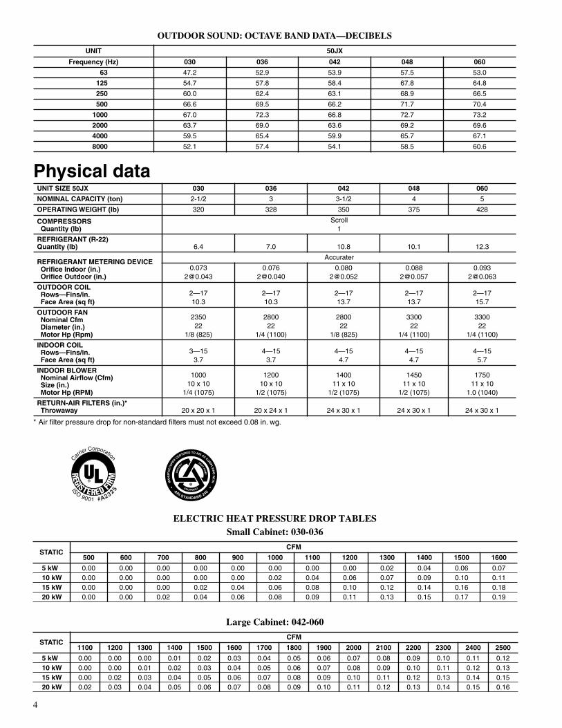
Economizer with solid-state controls and barometric relief dampers
includes filter racks and provide outdoor air during cooling and reduce compressor operation.
Manual outside air damper
includes hood and filter rack with adjustable damper blade for up to 25% outdoor air.
Electric heaters
provide additional heat in the unit when required. Each package has a heater module that slides into the controls compartment. Heater sizes range from 5.0 to 20.0 kW. The electric heater design allows the use of a single-point power supply for the entire unit, resulting in lower installed costs.
Flat roof curbs
in both 8 in. and 14 in. sizes are available for roof mounted applications.
Square-to-round duct transition kit
enables 030-048 size units to be fitted to 14 in. round ductwork.
Thermostats
provide control for the system heating and cooling functions. Thermostat models are available in both programmable and non-programmable versions.
Controls upgrade kit
supplies high and low pressure safety protection and protects the unit from operating in unsuitable conditions.
Crankcase heater
provides anti-floodback protection for low-load cooling applications.
Rigging kit
includes lifting brackets which are inserted into the unit base rigging holds to lift unit for rooftop applications.
Low-ambient kit (Motormaster II control)
allows the use of mechanical cooling down to outdoor temperatures as low as 0°F.
Filter rack
features easy installation, serviceability, and high-filtering performance for vertical and horizontal applications.
Compressor Hard start kit
gives a boost to the compressor motor at each start-up.
Economizer with Solid-State Controls and Barometric
Relief Dampers
Manual Air Damper (25% open)
Electric Heaters
Filter Rack
Flat Roof Curbs (8-in. and 14-in.)
Square-to-Round Duct Transition Kit
Thermostats
Controls Upgrade Kit
Crankcase Heater
Rigging Kit
Low Ambient Kit (Motormaster® II Control)
Solid-State Time Guard® II Device
Compressor Hard Start Kit
Options and accessories
ELECTRIC HEATERS
LEGENDODS — Order Distribution SystemNOTE: Electric heaters are rated at 240 v and 480 v. Refer to Multiplication Factors table for other voltages.
*The 030 size models must be run on medium or high speed when used in conjunction with 15 kW electric heat accessory.
ODS CATALOG NOMINAL CAPACITY USED WITH SIZES
ORDERING NO. (kW) FUSED (YES/NO) STAGES 030 036 042 048 060ELECTRIC HEATERS (208/230 — 3 PHASE — 60 Hz)
CPHEATER055A00
3.8 / 5.0 NO 3 X X X X X
CPHEATER056A00
7.5 / 10.0 NO 3 X X X X
CPHEATER058A00
11.3 / 15.0 YES 3 X X X X X
CPHEATER059A01
15.0 / 20.0 YES 3 X X X
CPHEATER068A00
7.5 / 10.0 YES 3 X
ELECTRIC HEATERS (460 — 3 PHASE — 60 Hz)
CPHEATER060A00
3.8 / 5.0 NO 1 X X X X
CPHEATER061A00
7.5 / 10.0 NO 1 X X X X
CPHEATER062A00
11.3 / 15.0 NO 1 X X X X
CPHEATER063A00
15.0 / 20.0 NO 1 X X X
Minimum Airflow for Reliable Electric Heater Operation
UNIT-50JX 030 036 042 048 060
AIRFLOW 1000* 1200 1400 1600 2000
6
50JX
ECONOMIZER
FILTER RACK MANUAL OUTSIDE AIR DAMPER
DAMPERBLADE
MANUAL OUTSIDEAIR HOOD
REPLACEMENTPANEL
7

7
50JX
Base unit dimensions—50JX030-036
UNIT ELECTRICALCHARACTERISTICS
UNIT WEIGHT UNIT HEIGHTmm (in.)
“A”
CENTER OF GRAVITYmm (in.)
lb kg X Y Z
50JX030 208/230-3-60 320 145.2 940.3 (37.02) 500.4 (19.7) 355.6 (14.0) 447.0 (17.6)
50JX036 208/230-3-60, 460-3-60 328 148.8 940.3 (37.02) 500.4 (19.7) 355.6 (14.0) 419.1 (16.5)

8
50JX
Base unit dimensions—50JX042-060
UNIT ELECTRICALCHARACTERISTICS
UNIT WEIGHT UNIT HEIGHTmm (in.)
“A”
CENTER OF GRAVITYmm (in.)
lb kg X Y Z
50JX042 208/230-3-60, 460-3-60 350 158.8 1040.9 (40.98) 505.5 (19.9) 398.8 (15.7) 421.6 (16.6)
50JX048 208/230-3-60, 460-3-60 375 170.1 1040.9 (40.98) 505.5 (19.9) 398.8 (15.7) 457.2 (18.0)
50JX060 208/230-3-60, 460-3-60 428 194.1 1091.7 (42.98) 505.5 (19.9) 398.8 (15.7) 447.0 (17.6)
9
50JX
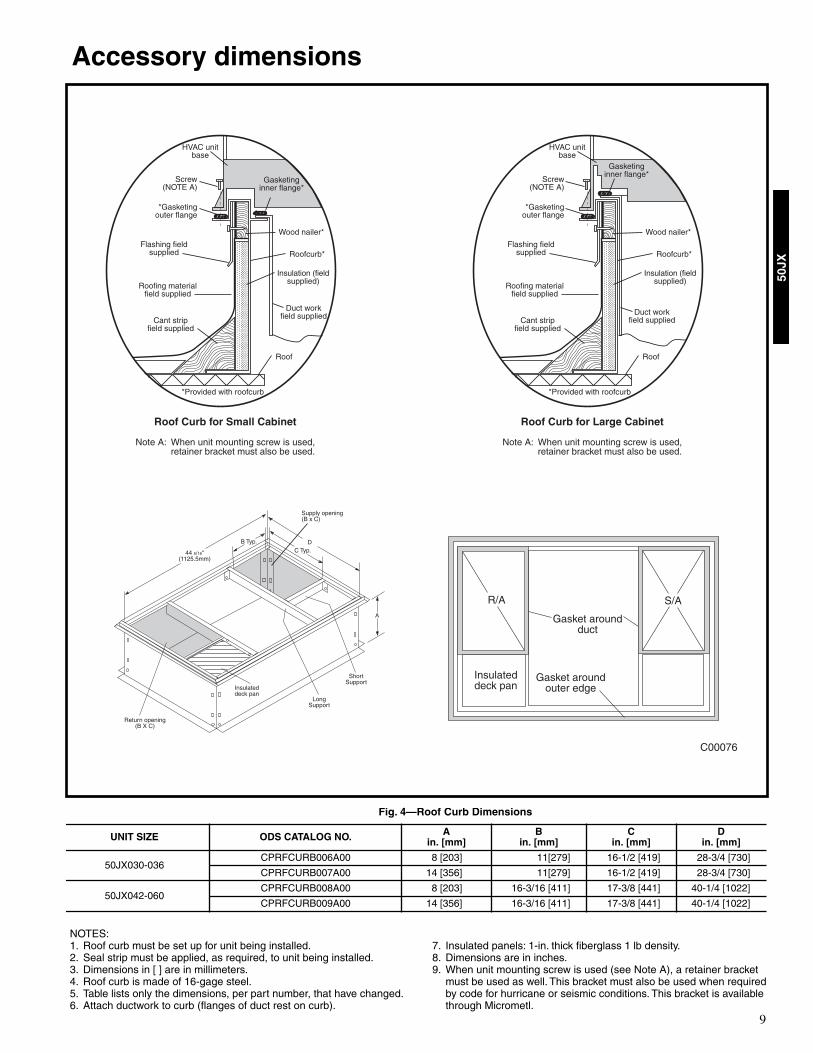
Accessory dimensions
NOTES:1. Roof curb must be set up for unit being installed.2. Seal strip must be applied, as required, to unit being installed.3. Dimensions in [ ] are in millimeters.4. Roof curb is made of 16-gage steel.5. Table lists only the dimensions, per part number, that have changed.6. Attach ductwork to curb (flanges of duct rest on curb).
7. Insulated panels: 1-in. thick fiberglass 1 lb density.8. Dimensions are in inches.9. When unit mounting screw is used (see Note A), a retainer bracket
must be used as well. This bracket must also be used when required by code for hurricane or seismic conditions. This bracket is available through Micrometl.
Fig. 4—Roof Curb Dimensions
UNIT SIZE ODS CATALOG NO. Ain. [mm]
Bin. [mm]
Cin. [mm]
Din. [mm]
50JX030-036CPRFCURB006A00 8 [203] 11[279] 16-1/2 [419] 28-3/4 [730]
CPRFCURB007A00 14 [356] 11[279] 16-1/2 [419] 28-3/4 [730]
50JX042-060CPRFCURB008A00 8 [203] 16-3/16 [411] 17-3/8 [441] 40-1/4 [1022]
CPRFCURB009A00 14 [356] 16-3/16 [411] 17-3/8 [441] 40-1/4 [1022]
C00076
Gasket aroundouter edge
Insulateddeck pan
Gasket aroundduct
S/AR/A
HVAC unitbase
*Gasketingouter flange
Flashing fieldsupplied
Roofing materialfield supplied
Cant stripfield supplied
*Provided with roofcurb
Roof
Duct workfield supplied
Insulation (fieldsupplied)
Roofcurb*
Wood nailer*
Gasketinginner flange*
Screw(NOTE A)
Roof Curb for Small Cabinet
Note A: When unit mounting screw is used,retainer bracket must also be used.
HVAC unitbase
*Gasketingouter flange
Flashing fieldsupplied
Roofing materialfield supplied
Cant stripfield supplied
*Provided with roofcurb
Roof
Duct workfield supplied
Insulation (fieldsupplied)
Roofcurb*
Wood nailer*
Gasketinginner flange*
Screw(NOTE A)
Roof Curb for Large Cabinet
Note A: When unit mounting screw is used,retainer bracket must also be used.
A
B Typ.
Supply opening(B x C)
LongSupport
D
44 5/16"(1125.5mm)
Return opening(B X C)
Insulateddeck pan
ShortSupport
C Typ.
10
50JX
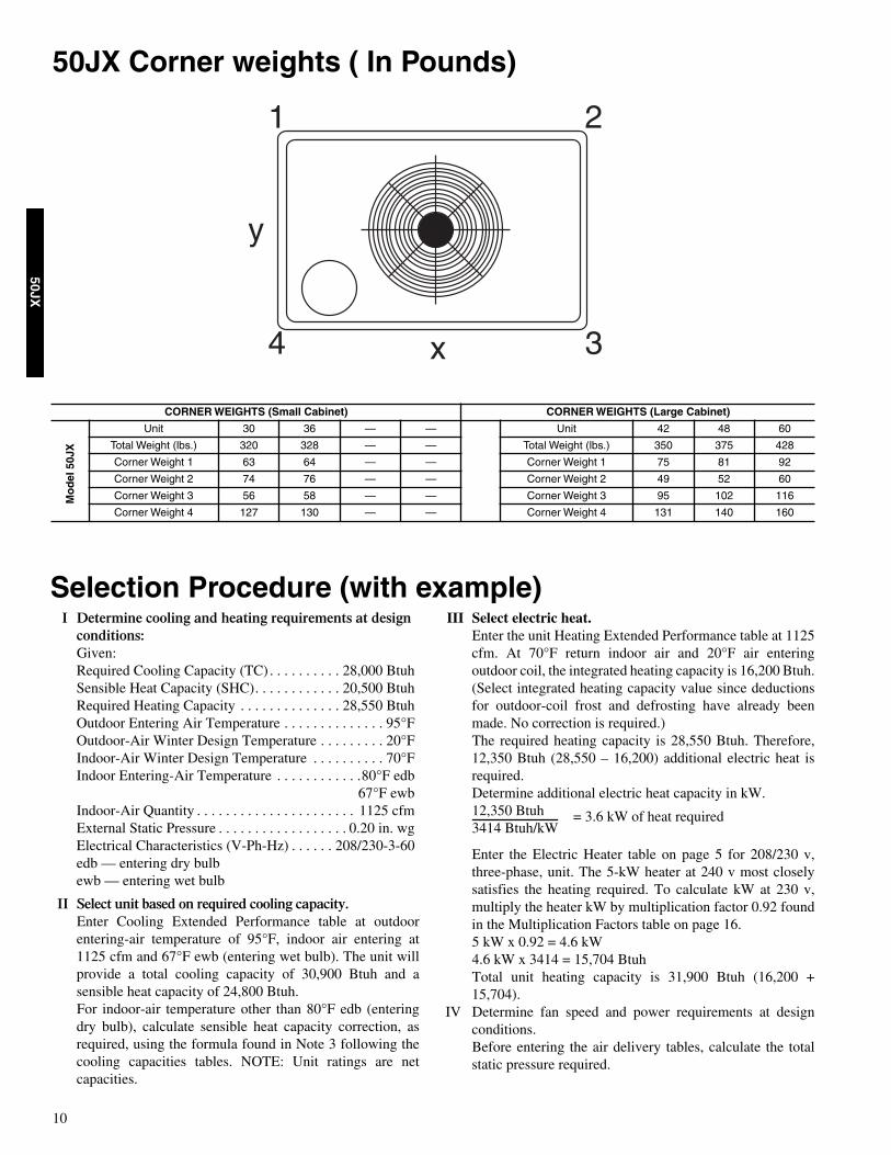
50JX Corner weights ( In Pounds)
I Determine cooling and heating requirements at design conditions:Given:Required Cooling Capacity (TC) . . . . . . . . . . 28,000 BtuhSensible Heat Capacity (SHC). . . . . . . . . . . . 20,500 BtuhRequired Heating Capacity . . . . . . . . . . . . . . 28,550 BtuhOutdoor Entering Air Temperature . . . . . . . . . . . . . . 95°FOutdoor-Air Winter Design Temperature . . . . . . . . . 20°F Indoor-Air Winter Design Temperature . . . . . . . . . . 70°FIndoor Entering-Air Temperature . . . . . . . . . . . .80°F edb
67°F ewbIndoor-Air Quantity . . . . . . . . . . . . . . . . . . . . . . 1125 cfmExternal Static Pressure . . . . . . . . . . . . . . . . . . 0.20 in. wgElectrical Characteristics (V-Ph-Hz) . . . . . . 208/230-3-60edb — entering dry bulbewb — entering wet bulb
II Select unit based on required cooling capacity.Enter Cooling Extended Performance table at outdoorentering-air temperature of 95°F, indoor air entering at1125 cfm and 67°F ewb (entering wet bulb). The unit willprovide a total cooling capacity of 30,900 Btuh and asensible heat capacity of 24,800 Btuh.For indoor-air temperature other than 80°F edb (enteringdry bulb), calculate sensible heat capacity correction, asrequired, using the formula found in Note 3 following thecooling capacities tables. NOTE: Unit ratings are netcapacities.
III Select electric heat.Enter the unit Heating Extended Performance table at 1125cfm. At 70°F return indoor air and 20°F air enteringoutdoor coil, the integrated heating capacity is 16,200 Btuh.(Select integrated heating capacity value since deductionsfor outdoor-coil frost and defrosting have already beenmade. No correction is required.)The required heating capacity is 28,550 Btuh. Therefore,12,350 Btuh (28,550 – 16,200) additional electric heat isrequired.Determine additional electric heat capacity in kW.12,350 Btuh3414 Btuh/kW
Enter the Electric Heater table on page 5 for 208/230 v,three-phase, unit. The 5-kW heater at 240 v most closelysatisfies the heating required. To calculate kW at 230 v,multiply the heater kW by multiplication factor 0.92 foundin the Multiplication Factors table on page 16.5 kW x 0.92 = 4.6 kW4.6 kW x 3414 = 15,704 BtuhTotal unit heating capacity is 31,900 Btuh (16,200 +15,704).
IV Determine fan speed and power requirements at designconditions.Before entering the air delivery tables, calculate the totalstatic pressure required.
= 3.6 kW of heat required
Selection Procedure (with example)
1 2
4 3x
y
CORNER WEIGHTS (Small Cabinet) CORNER WEIGHTS (Large Cabinet)
Unit 30 36 — — Unit 42 48 60
Total Weight (lbs.) 320 328 — — Total Weight (lbs.) 350 375 428
Corner Weight 1 63 64 — — Corner Weight 1 75 81 92
Corner Weight 2 74 76 — — Corner Weight 2 49 52 60
Corner Weight 3 56 58 — — Corner Weight 3 95 102 116
Corner Weight 4 127 130 — — Corner Weight 4 131 140 160
Mo
del
50J
X

11
50JX
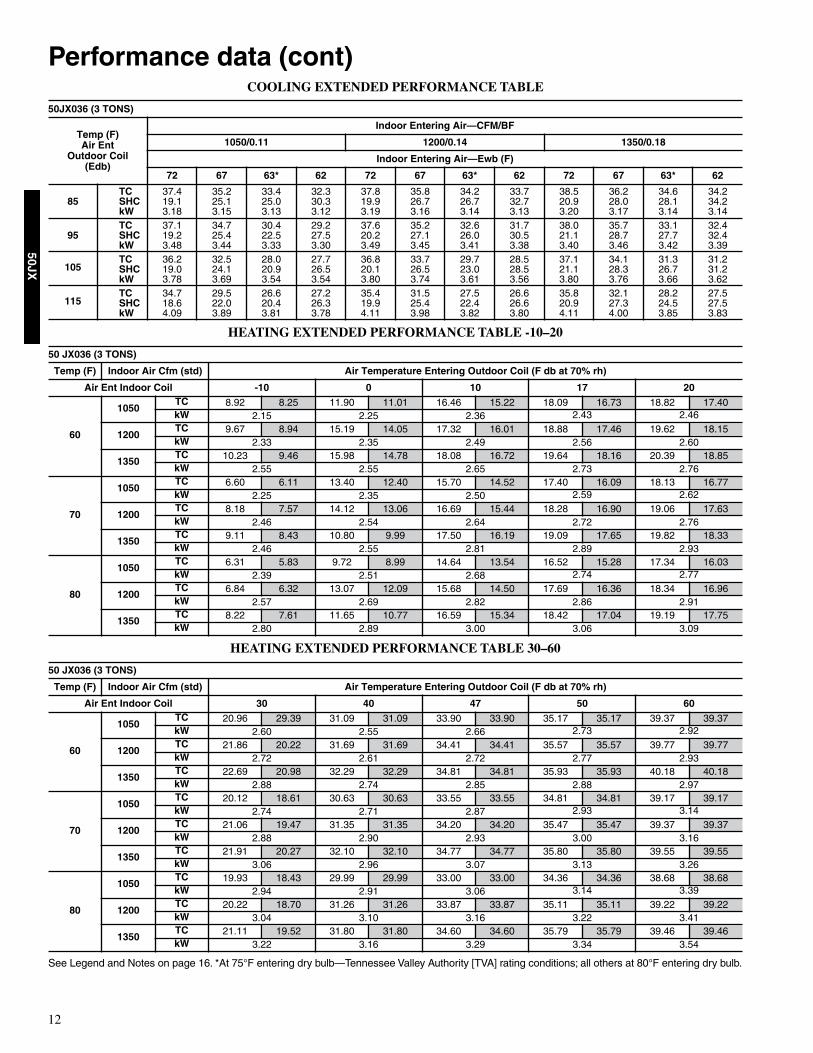
Performance data COOLING EXTENDED PERFORMANCE TABLE
HEATING EXTENDED PERFORMANCE TABLE -10–20
HEATING EXTENDED PERFORMANCE TABLE 30–60
See Legend and Notes on page 16. *At 75°F entering dry bulb—Tennessee Valley Authority [TVA] rating conditions; all others at 80°F entering dry bulb.
50JX030 (2-1/2 TONS)
Temp (F)Air Ent
Outdoor Coil(Edb)
Indoor Entering Air—CFM/BF
875/0.05 1000/0.06 1125/0.08
Indoor Entering Air—Ewb (F)
72 67 63* 62 72 67 63* 62 72 67 63* 62
85TC 34.1 31.8 29.1 28.7 34.4 32.0 29.6 29.0 34.3 32.0 30.1 29.6SHC 17.8 22.9 21.6 26.8 18.3 24.2 23.1 28.1 18.7 24.0 24.4 29.6kW 2.36 2.37 2.39 2.36 2.45 2.47 2.50 2.44 2.57 2.59 2.59 2.54
95TC 33.2 30.1 27.9 27.5 33.4 29.5 28.1 27.9 33.5 30.9 28.2 27.8SHC 17.5 22.0 21.1 26.4 18.1 22.8 22.3 27.5 18.5 24.8 23.2 27.8kW 2.67 2.69 2.68 2.64 2.76 2.78 2.79 2.72 2.88 2.89 2.90 2.82
105TC 31.9 28.7 26.5 26.2 32.4 29.1 26.6 26.4 32.1 29.6 26.8 27.1SHC 17.0 21.44 20.6 25.7 18.1 22.9 21.7 26.4 18.2 24.4 22.7 27.1kW 3.01 3.02 3.00 2.95 3.07 3.12 3.09 3.03 3.23 3.21 3.20 3.13
115TC 30.5 27.0 24.9 24.4 30.6 27.2 25.1 25.5 30.6 27.3 25.1 25.9SHC 16.7 20.8 19.9 24.4 17.2 21.9 21.1 25.5 17.7 23.0 22.0 25.9kW 3.38 3.36 3.33 3.28 3.48 3.46 3.43 3.37 3.59 3.56 3.55 3.48
50 JX030 (2-1/2 TONS)
Temp (F) Indoor Air Cfm (std) Air Temperature Entering Outdoor Coil (F db at 70% rh)
Air Ent Indoor Coil -10 0 10 17 20
60
875Cap. 9.33 8.58 11.76 10.82 12.89 11.86 16.26 14.96 17.29 15.91kW 1.75 1.82 1.70 1.92 1.94
1000Cap. 9.69 8.92 12.27 11.29 15.02 13.82 16.62 15.29 17.78 16.36kW 1.82 1.87 1.90 1.98 2.02
1125Cap. 10.11 9.31 12.74 11.72 15.47 14.23 17.13 15.76 18.11 16.66kW 1.99 1.95 1.99 2.05 2.05
70
875Cap. 6.14 5.65 11.04 10.16 13.93 12.81 16.58 15.26 16.72 15.38kW 1.99 1.97 2.01 2.48 2.09
1000Cap. 8.82 8.11 11.58 10.66 14.36 13.21 16.38 15.06 17.13 15.75kW 1.96 2.03 2.09 2.13 2.16
1125Cap. 9.32 8.58 11.94 10.99 14.84 13.66 16.85 15.51 17.61 16.20kW 2.06 2.08 2.18 2.22 2.24
80
875Cap. 7.35 6.76 10.12 9.31 12.67 11.66 15.23 14.01 16.17 14.88kW 2.04 2.16 2.22 2.28 2.30
1000Cap. 7.74 7.13 10.71 9.86 13.44 12.37 15.71 14.46 16.68 15.35kW 2.13 2.23 2.19 2.33 2.34
1125Cap. 8.22 7.56 11.07 10.18 14.06 12.94 16.24 14.94 17.20 15.83kW 2.24 2.32 2.39 2.42 2.43
50 JX030 (2-1/2 TONS)
Temp (F) Indoor Air Cfm (std) Air Temperature Entering Outdoor Coil (F db at 70% rh)
Air Ent Indoor Coil 30 40 47 50 60
60
875Cap. 20.22 18.60 25.04 25.04 28.62 28.62 29.88 29.88 34.18 34.18kW 1.95 1.86 2.07 2.08 2.13
1000Cap. 20.67 19.02 26.18 26.18 28.82 28.82 30.02 30.02 34.84 34.84kW 1.98 2.04 2.07 2.09 2.12
1125Cap. 21.16 19.47 26.52 26.52 29.60 29.60 30.04 30.04 34.89 34.89kW 2.06 2.11 2.06 2.13 2.14
70
875Cap. 19.95 18.35 25.29 25.29 28.10 18.68 29.32 29.31 33.61 33.61kW 2.23 2.25 2.30 2.34 2.40
1000Cap. 20.16 18.55 25.80 25.79 28.37 28.37 29.57 29.57 33.62 33.62kW 2.23 2.29 2.32 2.34 2.38
1125Cap. 20.55 18.91 26.12 26.12 28.59 28.59 29,70 29.70 33.74 33.74kW 2.31 2.34 2.37 2.39 2.40
80
875Cap. 19.18 17.65 24.91 24.91 27.49 27.49 28.74 28.74 33.00 33.00kW 2.40 2.52 2.59 2.60 2.68
1000Cap. 19.46 17.91 25.31 25.31 27.93 27.93 29.09 29.09 33.18 33.18kW 2.46 2.54 2.61 2.61 2.67
1125Cap. 19.93 18.34 25.73 25.73 28.25 28.25 29.41 29.41 33.15 33.15kW 2.52 2.61 2.63 2.66 2.70
12
50JX
Performance data (cont)COOLING EXTENDED PERFORMANCE TABLE
HEATING EXTENDED PERFORMANCE TABLE -10–20
HEATING EXTENDED PERFORMANCE TABLE 30–60
See Legend and Notes on page 16. *At 75°F entering dry bulb—Tennessee Valley Authority [TVA] rating conditions; all others at 80°F entering dry bulb.
50JX036 (3 TONS)
Temp (F)Air Ent
Outdoor Coil(Edb)
Indoor Entering Air—CFM/BF
1050/0.11 1200/0.14 1350/0.18
Indoor Entering Air—Ewb (F)
72 67 63* 62 72 67 63* 62 72 67 63* 62
85TC 37.4 35.2 33.4 32.3 37.8 35.8 34.2 33.7 38.5 36.2 34.6 34.2SHC 19.1 25.1 25.0 30.3 19.9 26.7 26.7 32.7 20.9 28.0 28.1 34.2kW 3.18 3.15 3.13 3.12 3.19 3.16 3.14 3.13 3.20 3.17 3.14 3.14
95TC 37.1 34.7 30.4 29.2 37.6 35.2 32.6 31.7 38.0 35.7 33.1 32.4SHC 19.2 25.4 22.5 27.5 20.2 27.1 26.0 30.5 21.1 28.7 27.7 32.4kW 3.48 3.44 3.33 3.30 3.49 3.45 3.41 3.38 3.40 3.46 3.42 3.39
105TC 36.2 32.5 28.0 27.7 36.8 33.7 29.7 28.5 37.1 34.1 31.3 31.2SHC 19.0 24.1 20.9 26.5 20.1 26.5 23.0 28.5 21.1 28.3 26.7 31.2kW 3.78 3.69 3.54 3.54 3.80 3.74 3.61 3.56 3.80 3.76 3.66 3.62
115TC 34.7 29.5 26.6 27.2 35.4 31.5 27.5 26.6 35.8 32.1 28.2 27.5SHC 18.6 22.0 20.4 26.3 19.9 25.4 22.4 26.6 20.9 27.3 24.5 27.5kW 4.09 3.89 3.81 3.78 4.11 3.98 3.82 3.80 4.11 4.00 3.85 3.83
50 JX036 (3 TONS)
Temp (F) Indoor Air Cfm (std) Air Temperature Entering Outdoor Coil (F db at 70% rh)
Air Ent Indoor Coil -10 0 10 17 20
60
1050TC 8.92 8.25 11.90 11.01 16.46 15.22 18.09 16.73 18.82 17.40kW 2.15 2.25 2.36 2.43 2.46
1200TC 9.67 8.94 15.19 14.05 17.32 16.01 18.88 17.46 19.62 18.15kW 2.33 2.35 2.49 2.56 2.60
1350TC 10.23 9.46 15.98 14.78 18.08 16.72 19.64 18.16 20.39 18.85kW 2.55 2.55 2.65 2.73 2.76
70
1050TC 6.60 6.11 13.40 12.40 15.70 14.52 17.40 16.09 18.13 16.77kW 2.25 2.35 2.50 2.59 2.62
1200TC 8.18 7.57 14.12 13.06 16.69 15.44 18.28 16.90 19.06 17.63kW 2.46 2.54 2.64 2.72 2.76
1350TC 9.11 8.43 10.80 9.99 17.50 16.19 19.09 17.65 19.82 18.33kW 2.46 2.55 2.81 2.89 2.93
80
1050TC 6.31 5.83 9.72 8.99 14.64 13.54 16.52 15.28 17.34 16.03kW 2.39 2.51 2.68 2.74 2.77
1200TC 6.84 6.32 13.07 12.09 15.68 14.50 17.69 16.36 18.34 16.96kW 2.57 2.69 2.82 2.86 2.91
1350TC 8.22 7.61 11.65 10.77 16.59 15.34 18.42 17.04 19.19 17.75kW 2.80 2.89 3.00 3.06 3.09
50 JX036 (3 TONS)
Temp (F) Indoor Air Cfm (std) Air Temperature Entering Outdoor Coil (F db at 70% rh)
Air Ent Indoor Coil 30 40 47 50 60
60
1050TC 20.96 29.39 31.09 31.09 33.90 33.90 35.17 35.17 39.37 39.37kW 2.60 2.55 2.66 2.73 2.92
1200TC 21.86 20.22 31.69 31.69 34.41 34.41 35.57 35.57 39.77 39.77kW 2.72 2.61 2.72 2.77 2.93
1350TC 22.69 20.98 32.29 32.29 34.81 34.81 35.93 35.93 40.18 40.18kW 2.88 2.74 2.85 2.88 2.97
70
1050TC 20.12 18.61 30.63 30.63 33.55 33.55 34.81 34.81 39.17 39.17kW 2.74 2.71 2.87 2.93 3.14
1200TC 21.06 19.47 31.35 31.35 34.20 34.20 35.47 35.47 39.37 39.37kW 2.88 2.90 2.93 3.00 3.16
1350TC 21.91 20.27 32.10 32.10 34.77 34.77 35.80 35.80 39.55 39.55kW 3.06 2.96 3.07 3.13 3.26
80
1050TC 19.93 18.43 29.99 29.99 33.00 33.00 34.36 34.36 38.68 38.68kW 2.94 2.91 3.06 3.14 3.39
1200TC 20.22 18.70 31.26 31.26 33.87 33.87 35.11 35.11 39.22 39.22kW 3.04 3.10 3.16 3.22 3.41
1350TC 21.11 19.52 31.80 31.80 34.60 34.60 35.79 35.79 39.46 39.46kW 3.22 3.16 3.29 3.34 3.54

13
50JX
Performance data (cont)COOLING EXTENDED PERFORMANCE TABLE
HEATING EXTENDED PERFORMANCE TABLE -10–20
HEATING EXTENDED PERFORMANCE TABLE 30–60
See Legend and Notes on page 16. *At 75°F entering dry bulb—Tennessee Valley Authority [TVA] rating conditions; all others at 80°F entering dry bulb.
50 JX042 (3-1/2 TONS)
Temp (F)Air Ent
Outdoor Coil(Edb)
Indoor Entering Air—CFM/BF
1225/0.06 1400/0.06 1575/0.07
Indoor Entering Air—Ewb (F)
72 67 63* 62 72 67 63* 62 72 67 63* 62
85TC 46.7 42.8 40.2 39.4 47.1 43.2 40.2 40.1 47.2 43.3 40.2 40.8SHC 24.3 30.7 31.3 37.3 25.1 32.5 32.8 39.6 25.7 33.9 34.4 40.8kW 3.43 3.40 3.53 3.31 3.58 3.54 3.72 3.41 3.75 3.71 3.92 3.52
95TC 45.1 41.0 38.1 37.4 45.4 41.5 38.2 38.7 45.4 41.5 38.1 39.7SHC 23.7 29.9 30.1 36.1 24.5 31.8 31.8 38.7 25.2 33.3 33.2 39.7kW 3.78 3.74 3.83 3.60 3.94 3.91 4.02 3.69 4.12 4.07 4.25 3.86
105TC 43.5 38.8 35.9 35.6 43.5 39.2 35.9 36.8 43.5 39.4 35.8 37.9SHC 23.3 28.7 29.1 35.4 23.9 30.6 30.6 36.8 24.7 32.3 32.0 37.9kW 4.17 4.07 4.13 3.91 4.33 4.24 4.33 4.03 4.51 4.40 4.56 4.20
115TC 41.0 36.6 33.8 34.0 41.2 36.9 33.8 35.2 41.3 36.9 33.7 35.9SHC 22.1 27.9 28.3 34.0 23.0 29.6 29.8 35.2 23.7 31.1 31.3 35.9kW 4.59 4.44 4.50 4.26 4.75 4.58 4.70 4.42 4.94 4.76 4.90 4.57
50 JX042 (3-1/2 TONS)
Temp (F) Indoor Air Cfm (std) Air Temperature Entering Outdoor Coil (F db at 70% rh)
Air Ent Indoor Coil -10 0 10 17 20
60
1225TC 12.32 11.34 16.82 15.48 20.83 19.16 24.26 22.33 25.64 23.60kW 2.38 2.50 2.61 2.68 2.71
1400TC 13.56 12.47 17.91 16.48 21.69 19.96 25.15 23.14 26.50 24.38kW 2.56 2.66 2.74 2.80 2.84
1575TC 15.37 14.14 19.47 17.91 22.32 20.54 25.76 23.71 27.08 24.92kW 2.71 2.80 2.89 2.91 2.96
70
1225TC 10.27 9.45 15.14 13.93 19.86 18.27 23.10 21.25 24.51 22.55kW 2.55 2.70 2.86 2.93 2.97
1400TC 11.36 10.45 16.19 14.89 20.55 18.91 24.03 22.11 25.46 23.42kW 2.72 2.85 2.99 3.06 3.08
1575TC 11.80 10.85 16.48 15.17 21.17 19.47 24.68 22.70 26.09 24.00kW 2.86 2.97 3.11 3.18 3.20
80
1225TC 7.25 6.67 12.43 11.44 18.54 17.06 21.87 20.12 23.20 21.35kW 2.73 2.90 3.10 3.22 3.25
1400TC 8.50 7.82 13.58 12.49 18.39 16.92 22.84 21.02 24.21 22.27kW 2.96 3.10 3.19 3.35 3.38
1575TC 9.12 8.39 14.20 13.06 18.85 17.35 23.51 21.63 24.90 22.91kW 3.09 3.21 3.34 3.47 3.49
50 JX042 (3-1/2 TONS)
Temp (F) Indoor Air Cfm (std) Air Temperature Entering Outdoor Coil (F db at 70% rh)
Air Ent Indoor Coil 30 40 47 50 60
60
1225TC 30.15 27.74 36.33 36.33 38.87 38.87 39.69 39.69 42.11 42.11kW 2.88 3.00 3.12 3.15 3.24
1400TC 31.06 28.58 37.25 37.25 39.30 39.30 40.14 40.14 42.28 42.28kW 3.00 3.12 3.18 3.21 3.28
1575TC 31.68 29.15 37.83 37.83 39.73 39.73 40.47 40.47 42.54 42.54kW 3.12 3.19 3.26 3.28 3.35
70
1225TC 29.23 26.89 35.41 35.41 39.11 39.11 40.46 40.46 43.21 43.21kW 3.10 3.24 3.46 3.49 3.62
1400TC 30.16 27.75 36.46 36.46 40.08 40.08 41.02 41.02 43.67 43.67kW 3.23 3.40 3.51 3.55 3.65
1575TC 30.81 28.35 37.01 37.01 40.58 40.58 41.43 41.43 44.00 44.00kW 3.34 3.42 3.59 3.63 3.72
80
1225TC 28.04 25.80 34.82 34.82 38.24 38.24 39.84 39.84 43.96 43.96kW 3.38 3.51 3.66 3.75 4.01
1400TC 29.09 26.76 35.72 35.72 39.31 39.31 41.00 41.00 44.55 44.55kW 3.49 3.61 3.81 3.86 4.03
1575TC 29.79 27.41 36.41 36.41 39.95 39.95 41.72 41.72 45.08 45.08kW 3.61 3.70 3.93 3.98 4.11

14
50JX
Performance data (cont)COOLING EXTENDED PERFORMANCE TABLE
HEATING EXTENDED PERFORMANCE TABLE -10–20
HEATING EXTENDED PERFORMANCE TABLE 30–60
See Legend and Notes on page 16. *At 75°F entering dry bulb—Tennessee Valley Authority [TVA] rating conditions; all others at 80°F entering dry bulb.
50 JX048 (4 TONS)
Temp (F)Air Ent
Outdoor Coil(Edb)
Indoor Entering Air—CFM/BF
1400/0.07 1600/0.07 1800/0.08
Indoor Entering Air—Ewb (F)
72 67 63* 62 72 67 63* 62 72 67 63* 62
85TC 52.8 48.7 45.2 44.5 53.0 48.9 45.5 45.5 52.9 49.0 45.6 46.4SHC 25.2 32.5 31.3 39.2 26.0 34.1 33.0 41.2 26.5 35.6 34.5 41.8kW 4.0 4.0 3.9 3.9 4.2 4.2 4.1 4.0 4.4 4.3 4.3 4.1
95TC 51.1 46.9 43.0 42.9 51.3 47.1 43.6 44.0 51.2 47.2 43.7 44.9SHC 24.7 32.0 29.9 38.4 25.5 33.7 32.2 39.8 26.3 35.3 33.6 40.9kW 4.4 4.4 4.3 4.2 4.6 4.6 4.5 4.3 4.8 4.7 4.6 4.5
105TC 49.3 44.8 41.3 41.1 49.4 45.0 41.7 42.3 49.3 45.0 41.7 43.3SHC 24.2 31.3 29.8 37.2 25.1 33.1 31.6 38.4 25.8 34.8 32.9 39.1kW 4.9 4.8 4.7 4.6 5.1 5.0 4.8 4.7 5.3 5.2 5.0 4.9
115TC 47.1 42.5 39.2 39.5 47.3 42.7 39.5 40.5 47.2 42.8 39.4 41.3SHC 23.6 30.5 28.9 35.8 24.5 32.3 30.6 37.2 25.2 34.0 32.1 38.1kW 5.4 5.2 5.1 5.0 5.6 5.4 5.2 5.2 5.8 5.6 5.4 5.3
50 JX048 (4 TONS)
Temp (F) Indoor Air Cfm (std) Air Temperature Entering Outdoor Coil (F db at 70% rh)
Air Ent Indoor Coil -10 0 10 17 20
60
1400TC 13.75 12.72 18.17 16.72 22.58 20.73 27.90 25.44 27.16 24.63kW 2.60 2.85 3.11 3.29 3.33
1600TC 14.56 13.47 18.93 17.42 23.29 21.38 26.35 24.02 27.70 25.12kW 2.97 3.16 3.36 3.49 3.49
1800TC 15.63 14.45 19.92 18.33 24.21 22.23 27.22 24.82 28.47 25.82kW 3.21 3.37 3.54 3.65 3.65
70
1400TC 12.18 11.26 16.85 15.50 21.52 19.75 24.79 22.61 26.48 24.02kW 2.80 3.10 3.39 3.59 3.65
1600TC 13.21 12.22 17.80 16.38 22.40 20.56 25.61 23.35 27.15 24.62kW 2.98 3.23 3.49 3.67 3.71
1800TC 14.52 13.43 19.01 17.49 23.49 21.56 26.63 24.28 28.14 25.52kW 3.32 3.53 3.74 3.89 3.91
80
1400TC 12.79 11.83 18.22 16.77 21.89 20.10 24.67 22.49 25.82 23.42kW 2.98 3.40 3.66 3.82 3.92
1600TC 13.91 12.87 18.97 17.45 22.71 20.84 25.37 23.13 27.38 24.84kW 3.16 3.52 3.74 3.89 4.01
1800TC 14.60 13.51 19.52 17.96 23.05 21.15 26.58 24.23 28.08 25.46kW 3.52 3.75 4.04 4.18 4.22
50 JX048 (4 TONS)
Temp (F) Indoor Air Cfm (std) Air Temperature Entering Outdoor Coil (F db at 70% rh)
Air Ent Indoor Coil 30 40 47 50 60
60
1400TC 32.14 28.16 37.41 37.41 41.34 41.34 42.95 42.95 47.11 47.11kW 3.51 3.56 3.73 3.79 4.00
1600TC 32.85 28.79 38.08 38.08 42.03 42.03 43.43 43.43 47.50 47.50kW 3.58 3.83 3.71 3.77 3.94
1800TC 33.66 29.49 39.03 39.03 42.66 42.66 44.04 44.04 48.07 48.07kW 3.73 3.78 3.82 3.83 3.96
70
1400TC 31.48 27.58 37.06 37.06 41.24 41.24 42.79 42.79 47.50 47.50kW 3.82 3.98 4.09 4.17 4.44
1600TC 32.28 28.29 37.84 37.84 41.89 41.89 43.41 43.41 47.87 47.87kW 3.84 3.98 4.06 4.14 4.35
1800TC 33.18 29.08 38.65 38.65 42.65 42.65 44.09 44.09 48.47 48.47kW 3.98 4.08 4.15 4.21 4.35
80
1400TC 30.84 27.03 36.31 36.31 40.68 40.68 42.36 42.36 47.65 47.65kW 4.12 4.43 4.49 4.61 4.90
1600TC 32.48 28.46 37.20 37.20 41.55 41.55 42.96 42.96 48.21 48.21kW 4.18 4.31 4.43 4.51 4.81
1800TC 33.19 29.08 38.12 38.12 42.37 42.37 43.55 43.55 48.77 48.77kW 4.33 4.42 4.50 4.52 4.81
15
50JX
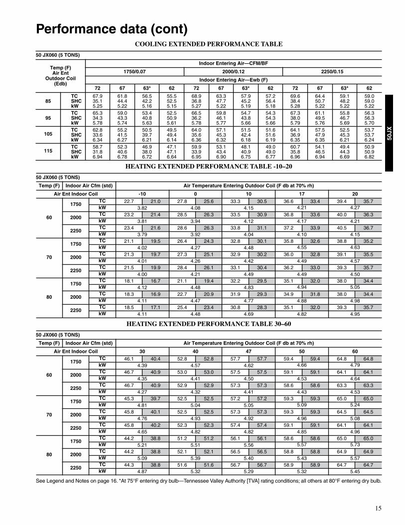
Performance data (cont)COOLING EXTENDED PERFORMANCE TABLE
HEATING EXTENDED PERFORMANCE TABLE -10–20
HEATING EXTENDED PERFORMANCE TABLE 30–60
See Legend and Notes on page 16. *At 75°F entering dry bulb—Tennessee Valley Authority [TVA] rating conditions; all others at 80°F entering dry bulb.
50 JX060 (5 TONS)
Temp (F)Air Ent
Outdoor Coil(Edb)
Indoor Entering Air—CFM/BF
1750/0.07 2000/0.12 2250/0.15
Indoor Entering Air—Ewb (F)
72 67 63* 62 72 67 63* 62 72 67 63* 62
85TC 67.9 61.8 56.5 55.5 68.9 63.3 57.9 57.2 69.6 64.4 59.1 59.0SHC 35.1 44.4 42.2 52.5 36.8 47.7 45.2 56.4 38.4 50.7 48.2 59.0kW 5.25 5.22 5.16 5.15 5.27 5.22 5.19 5.18 5.28 5.22 5.22 5.22
95TC 65.3 59.0 53.4 52.5 66.5 59.8 54.7 54.3 67.3 61.1 55.8 56.3SHC 34.3 43.3 40.8 50.9 36.2 46.1 43.8 54.3 38.0 49.5 46.7 56.3kW 5.78 5.74 5.63 5.61 5.78 5.77 5.66 5.66 5.79 5.76 5.69 5.70
105TC 62.8 55.2 50.5 49.5 64.0 57.1 51.5 51.6 64.1 57.5 52.5 53.7SHC 33.6 41.5 39.7 49.4 35.6 45.3 42.4 51.6 36.9 47.9 45.3 53.7kW 6.34 6.27 6.21 6.14 6.36 6.32 6.18 6.19 6.35 6.35 6.21 6.24
115TC 58.7 52.3 46.9 47.1 59.9 53.1 48.1 49.0 60.7 54.1 49.4 50.9SHC 31.8 40.6 38.0 47.1 33.9 43.4 40.9 49.0 35.8 46.5 44.3 50.9kW 6.94 6.78 6.72 6.64 6.95 6.90 6.75 6.77 6.96 6.94 6.69 6.82
50 JX060 (5 TONS)
Temp (F) Indoor Air Cfm (std) Air Temperature Entering Outdoor Coil (F db at 70% rh)
Air Ent Indoor Coil -10 0 10 17 20
60
1750TC 22.7 21.0 27.8 25.6 33.3 30.5 36.6 33.4 39.4 35.7kW 3.82 4.08 4.15 4.21 4.27
2000TC 23.2 21.4 28.5 26.3 33.5 30.9 36.8 33.6 40.0 36.3kW 3.81 3.94 4.12 4.17 4.21
2250TC 23.4 21.6 28.6 26.3 33.8 31.1 37.2 33.9 40.5 36.7kW 3.79 3.92 4.04 4.10 4.15
70
1750TC 21.1 19.5 26.4 24.3 32.8 30.1 35.8 32.6 38.8 35.2kW 4.02 4.27 4.48 4.55 4.63
2000TC 21.3 19.7 27.3 25.1 32.9 30.2 36.0 32.8 39.1 35.5kW 4.01 4.26 4.42 4.49 4.57
2250TC 21.5 19.9 28.4 26.1 33.1 30.4 36.2 33.0 39.3 35.7kW 4.00 4.21 4.49 4.49 4.50
80
1750TC 18.1 16.7 21.1 19.4 32.2 29.5 35.1 32.0 38.0 34.4kW 4.12 4.48 4.83 4.94 5.05
2000TC 18.3 16.9 22.7 20.9 31.9 29.3 34.9 31.8 38.0 34.4kW 4.11 4.47 4.77 4.88 4.98
2250TC 18.5 17.1 25.4 23.4 30.8 28.3 35.1 32.0 39.3 35.7kW 4.11 4.48 4.69 4.82 4.95
50 JX060 (5 TONS)
Temp (F) Indoor Air Cfm (std) Air Temperature Entering Outdoor Coil (F db at 70% rh)
Air Ent Indoor Coil 30 40 47 50 60
60
1750TC 46.1 40.4 52.8 52.8 57.7 57.7 59.4 59.4 64.8 64.8kW 4.39 4.57 4.62 4.66 4.79
2000TC 46.7 40.9 53.0 53.0 57.5 57.5 59.1 59.1 64.1 64.1kW 4.35 4.41 4.50 4.53 4.64
2250TC 46.7 40.9 52.9 52.9 57.3 57.3 58.6 58.6 63.3 63.3kW 4.27 4.32 4.41 4.43 4.53
70
1750TC 45.3 39.7 52.5 52.5 57.2 57.2 59.3 59.3 65.0 65.0kW 4.81 5.04 5.05 5.09 5.24
2000TC 45.8 40.1 52.5 52.5 57.3 57.3 59.3 59.3 64.5 64.5kW 4.76 4.93 4.92 4.96 5.08
2250TC 45.8 40.2 52.3 52.3 57.4 57.4 59.1 59.1 64.1 64.1kW 4.65 4.82 4.82 4.85 4.96
80
1750TC 44.2 38.8 51.2 51.2 56.1 56.1 58.6 58.6 65.0 65.0kW 5.21 5.51 5.56 5.57 5.73
2000TC 44.2 38.8 52.1 52.1 56.5 56.5 58.8 58.8 64.9 64.9kW 5.09 5.39 5.40 5.43 5.57
2250TC 44.3 38.8 51.6 51.6 56.7 56.7 58.9 58.9 64.7 64.7kW 4.87 5.32 5.29 5.32 5.45
16
50JX
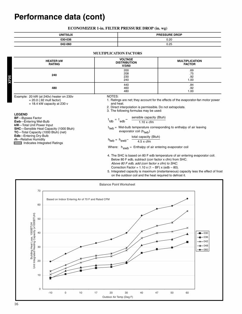
Performance data (cont)ECONOMIZER 1-in. FILTER PRESSURE DROP (in. wg)
MULTIPLICATION FACTORS
Example: 20 kW (at 240v) heater on 230v= 20.0 (.92 mult factor)= 18.4 kW capacity at 230 v
LEGENDBF—Bypass FactorEwb—Entering Wet-BulbkW—Total Unit Power InputSHC—Sensible Heat Capacity (1000 Btuh)TC—Total Capacity (1000 Btuh) (net)Edb—Entering Dry-Bulbrh—Relative Humidity
Indicates Integrated Ratings
UNIT50JX PRESSURE DROP
030-036 0.20
042-060 0.25
HEATER kWRATING
VOLTAGEDISTRIBUTION
V/3/60
MULTIPLICATIONFACTOR
240
200208230240
.69
.75
.921.00
480440460480
.84
.921.00
4. The SHC is based on 80 F edb temperature of air entering evaporator coil.Below 80 F edb, subtract (corr factor x cfm) from SHC.Above 80 F edb, add (corr factor x cfm) to SHC.Correction Factor = 1.10 x (1 – BF) x (edb – 80).
5. Integrated capacity is maximum (instantaneous) capacity less the effect of froston the outdoor coil and the heat required to defrost it.
NOTES:1. Ratings are net; they account for the effects of the evaporator-fan motor power
and heat.2. Direct interpolation is permissible. Do not extrapolate.3. The following formulas may be used:
Balance Point Worksheet
0
10
20
30
40
50
60
70
-10 0 10 17 20 30 40 47 50 60
Outdoor Air Temp (Deg F)
030
036
042
048
060
Based on Indoor Entering Air of 70 F and Rated CFM
Bui
ldin
g H
eat L
oss,
100
0BT
UH
Uni
t Int
egra
ted
Hea
ting
Cap
acity
(x1
000B
TU
H)
sensible capacity (Btuh)t = t �ldb edb 1.10 x cfm
t = Wet-bulb temperature corresponding to enthalpy of air leavinglwbevaporator coil (h )lwb
total capacity (Btuh)h = h �lwb ewb 4.5 x cfm
Where: h = Enthalpy of air entering evaporator coilewb

17
50JX
WET COIL AIR DELIVERY UNIT 50JX030-060*
*Air delivery values are based on operating voltage of 230 v or 460 v, wet coil, without filter or electric heater. Deduct filter and electric heater pressuredrops to obtain static pressure available for ducting.NOTES:1. Do not operate the unit at a cooling airflow that is less than 350 cfm for each 12,000 Btuh of rated cooling capacity. Evaporator coil frosting may
occur at airflows below this point.2. Dashes indicate portions of table that are beyond the blower motor capacity or are not recommended.3. Deduct 10% for 208v.
FILTER PRESSURE DROP (In. wg)
Unit 50JX Motor Speed
External Static Pressure (in.wg)
0.0 0.1 0.2 0.3 0.4 0.5 0.6 0.7 0.8 0.9 1.0
030
LowWatts 276 276 272 — — — — — — — —
Cfm 963 929 781 — — — — — — — —
MedWatts 375 377 371 362 354 350 — — — — —
Cfm 1202 1170 1079 976 884 807 — — — — —
HighWatts — — — — 469 449 435 428 — — —
Cfm — — — — 1174 988 828 718 — — —
036
LowWatts 462 451 431 411 394 381 — — — — —
Cfm 1374 1290 1205 1116 1020 916 — — — — —
MedWatts 523 506 490 471 449 426 — — — — —
Cfm 1500 1408 1301 1190 1082 977 — — — — —
HighWatts — 645 628 610 595 584 575 — — — —
Cfm — 1474 1369 1267 1169 1069 962 — — — —
042
LowWatts 620 600 586 574 562 548 530 510 487 462 439
Cfm 1662 1621 1581 1540 1496 1447 1392 1331 1263 1186 1103
MedWatts — — — — 686 661 634 606 577 547 517
Cfm — — — — 1722 1662 1594 1515 1427 1330 1227
HighWatts — — — — — — — 757 730 704 682
Cfm — — — — — — — 1669 1577 1486 1402
048
LowWatts 620 600 586 574 562 548 530 510 487 — —
Cfm 1662 1621 1581 1540 1496 1447 1392 1331 1263 — —
MedWatts 763 747 729 709 686 661 634 606 577 547 517
Cfm 1917 1868 1822 1774 1722 1662 1594 1515 1427 1330 1227
HighWatts — — — 852 832 809 784 757 730 704 682
Cfm — — — 1982 1914 1839 1757 1669 1577 1486 1402
060
LowWatts 597 592 578 526 460 452 445 — — — —
Cfm 2265 2190 2101 2033 1974 1869 1614 — — — —
MedWatts 754 730 707 687 671 658 646 630 603 558 486
Cfm 2383 2282 2202 2134 2070 2005 1935 1858 1771 1667 1576
HighWatts 901 876 856 836 813 785 755 723 696 687 681
Cfm 2480 2383 2301 2233 2175 2122 2066 1998 1910 1788 1619
UNIT SIZE 50JX FILTER SIZE
CFM
500 600 700 800 900 1000 1100 1200 1300 1400 1500 1600 1700 1800 1900 2000 2100 2200 2300
030 20 X 20 X 1 0.05 0.07 0.08 0.10 0.12 0.13 0.14 0.15 — — — — — — — — — — —
036 20 X 24 X 1 — — — — 0.09 0.10 0.11 0.13 0.14 0.15 0.16 — — — — — — — —
042, 048, 060 24 X 30 X 1 — — — — — — — 0.07 0.08 0.09 0.10 0.11 0.12 0.13 0.14 0.15 0.16 0.17 0.18

18
50JX
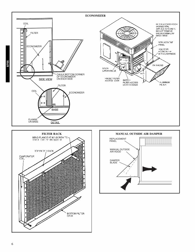
INDOORTHERMOSTAT
DISCONNECTPER NEC
FROMPOWERSOURCE
RETURNAIR
TOP COVER
Typical piping and wiring

19
50JX
Application dataCondensate trap — A 2-in. condensate trap must be fieldsupplied.
Ductwork — Secure downflow discharge ductwork to roofcurb. For horizontal discharge applications, attach ductworkto unit with flanges.
To convert a unit to downflow discharge — Units areequipped with factory-installed inserts in the downflowopenings. Remove the inserts similar to removing anelectrical knock-out. Maximum cooling airflow — To minimize the possibilityof condensate blow-off from the evaporator, airflow throughthe units should not exceed 450 cfm/ton.
Minimum cooling airflow — The minimum cooling airflowis 350 cfm/ton.
Minimum cooling ambient operating temperature — Allstandard units have a minimum ambient operatingtemperature of 40°F. With accessory low ambient temperaturekit, units can operate at temperatures down to 0°F.
1” MIN.
2” MIN.
TRAPOUTLET
20
50JX
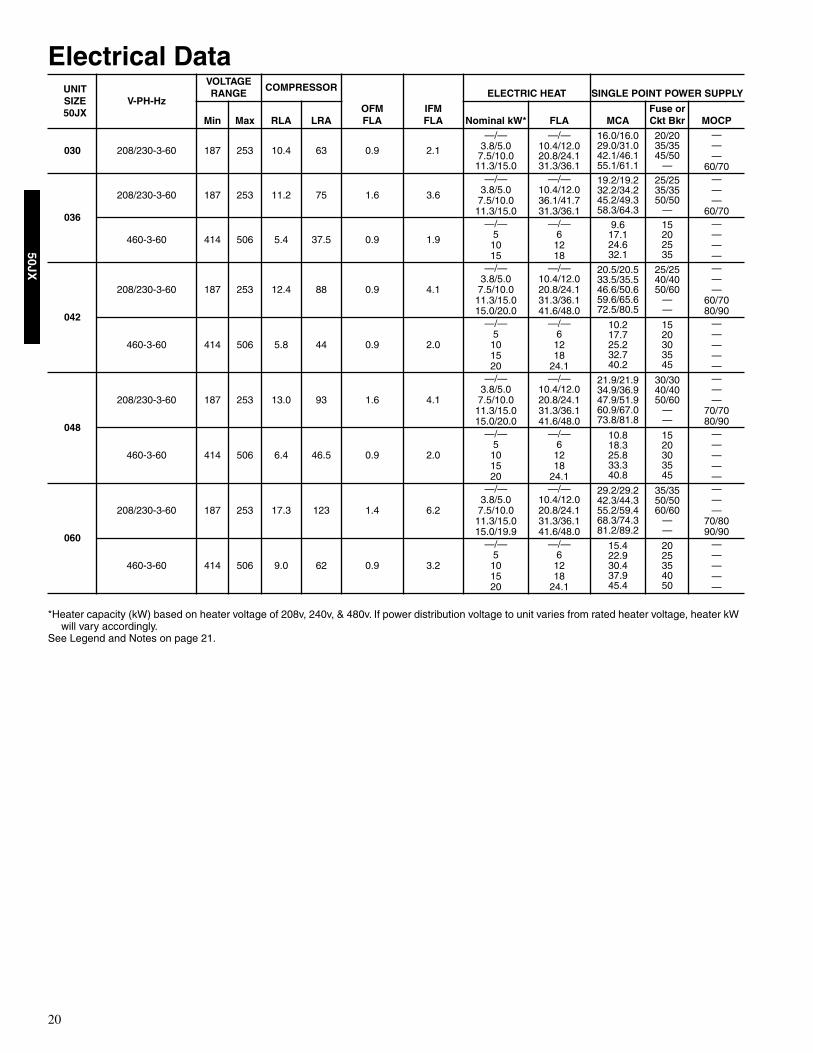
Electrical Data
*Heater capacity (kW) based on heater voltage of 208v, 240v, & 480v. If power distribution voltage to unit varies from rated heater voltage, heater kW will vary accordingly.
See Legend and Notes on page 21.
UNITSIZE50JX
V-PH-Hz
VOLTAGERANGE
COMPRESSOR
OFMFLA
IFMFLA
ELECTRIC HEAT SINGLE POINT POWER SUPPLY
Min Max RLA LRA Nominal kW* FLA MCAFuse or Ckt Bkr MOCP
030 208/230-3-60 187 253 10.4 63 0.9 2.1
—/—3.8/5.07.5/10.011.3/15.0
—/—10.4/12.020.8/24.131.3/36.1
16.0/16.029.0/31.042.1/46.155.1/61.1
20/2035/3545/50
—
———
60/70
036
208/230-3-60 187 253 11.2 75 1.6 3.6
—/—3.8/5.07.5/10.011.3/15.0
—/—10.4/12.036.1/41.731.3/36.1
19.2/19.232.2/34.245.2/49.358.3/64.3
25/2535/3550/50
—
———
60/70
460-3-60 414 506 5.4 37.5 0.9 1.9
—/—51015
—/—61218
9.617.124.632.1
15202535
————
042
208/230-3-60 187 253 12.4 88 0.9 4.1
—/—3.8/5.07.5/10.011.3/15.015.0/20.0
—/—10.4/12.020.8/24.131.3/36.141.6/48.0
20.5/20.533.5/35.546.6/50.659.6/65.672.5/80.5
25/2540/4050/60
——
———
60/7080/90
460-3-60 414 506 5.8 44 0.9 2.0
—/—5101520
—/—61218
24.1
10.217.725.232.740.2
1520303545
—————
048
208/230-3-60 187 253 13.0 93 1.6 4.1
—/—3.8/5.07.5/10.011.3/15.015.0/20.0
—/—10.4/12.020.8/24.131.3/36.141.6/48.0
21.9/21.934.9/36.947.9/51.960.9/67.073.8/81.8
30/3040/4050/60
——
———
70/7080/90
460-3-60 414 506 6.4 46.5 0.9 2.0
—/—5101520
—/—61218
24.1
10.818.325.833.340.8
1520303545
—————
060
208/230-3-60 187 253 17.3 123 1.4 6.2
—/—3.8/5.07.5/10.011.3/15.015.0/19.9
—/—10.4/12.020.8/24.131.3/36.141.6/48.0
29.2/29.242.3/44.355.2/59.468.3/74.381.2/89.2
35/3550/5060/60
——
———
70/8090/90
460-3-60 414 506 9.0 62 0.9 3.2
—/—5101520
—/—61218
24.1
15.422.930.437.945.4
2025354050
—————

21
50JX
Electrical Data Legend
452 = 5 v457 = 7 v455 = 2 v
LEGEND
FLA — Full Load AmpsLRA — Locked Rotor AmpsMCA — Minimum Circuit AmpsMOCP — Maximum Overcurrent ProtectionRLA — Rated Load Amps
NOTES:1. In compliance with NEC (National Electrical Code) requirements
for multimotor and combination load equipment (refer to NECArticles 430 and 440), the overcurrent protective device for theunit shall be Power Supply fuse . The CGA (Canadian GasAssociation) units may be fuse or circuit breaker.
2. Minimum wire size is based on 60 C copper wire. If other than60 C wire is used, or if length exceeds wire length in table,determine size from NEC.
3. Unbalanced 3-Phase Supply VoltageNever operate a motor where a phase imbalance in supply volt-age is greater than 2%. Use the following formula to determinethe percentage of voltage imbalance.
% Voltage imbalance
max voltage deviation from average voltage= 100 xaverage voltage
EXAMPLE: Supply voltage is 460-3-60.AB = 452 vBC = 464 vAC = 455 v
452 + 464 + 455Average Voltage =3
1371=3
= 457
Determine maximum deviation from average voltage.(AB) 457(BC) 464(AC) 457
Maximum deviation is 7 v.
Determine percent of voltage imbalance.7% Voltage Imbalance = 100 x
457
= 1.53%
This amount of phase imbalance is satisfactory as it is below themaximum allowable 2%.
IMPORTANT: If the supply voltage phase imbalance ismore than 2%, contact your local electric utility companyimmediately.
®
*Heater capacity (KW) based on heater voltage of 208v, 240v, & 480v.If power distribution voltage to unit varies from rated heater voltage,heater KW will vary accordingly.
22
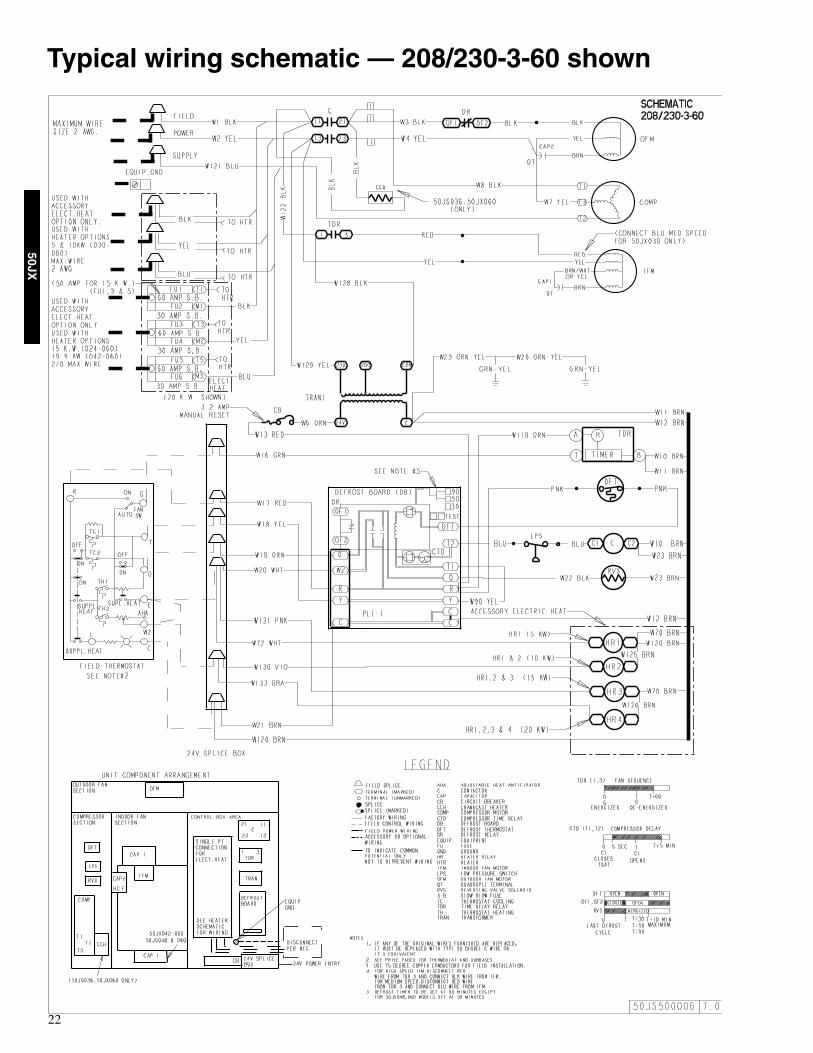
50JX
Typical wiring schematic — 208/230-3-60 shown
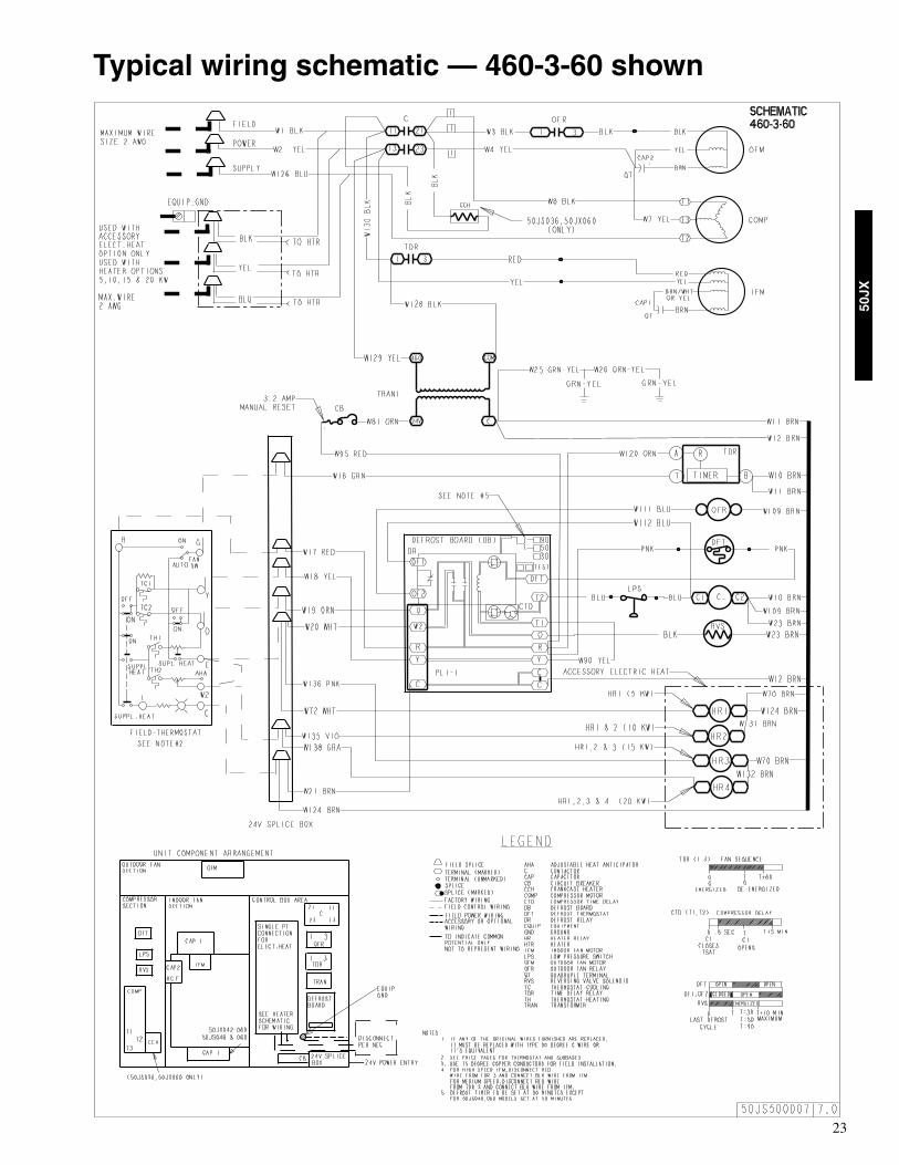
23
50JX
Typical wiring schematic — 460-3-60 shown
24
50JX
Sequence of operationWhen power is supplied to unit, the transformer (TRAN) isenergized.
On units with crankcase heater, heater is also energized.
Cooling — With the thermostat subbase in the coolingposition, the thermostat makes circuit R-O. This energizesthe reversing valve solenoid (RVS) and places the unit instandby condition for cooling.
As the space temperature rises, the thermostat makes,closing circuit R-Y. A circuit is made to contactor (C),starting the compressor (COMP) and outdoor-fan motor(OFM). Circuit R-G is made at the same time, energizing theindoor-fan relay (IFR) and starting the indoor-fan motor(IFM) after a 1-second delay.
When the thermostat is satisfied, contacts open, deenergizingC. The COMP and OFM stop, and the IFM stops after a 60second time delay.
Heating — On a call for heat, thermostat makes circuitsR-Y and R-G.
A circuit is made to C, starting COMP and OFM. Circuit R-G also is completed, energizing IFR and starting IFM aftera 1-second delay.
Should room temperature continue to fall, circuit R-W ismade through second-stage thermostat bulb. If optionalelectric heat package is used, a relay is energized, bringingon first bank of supplemental electric heat. When thermostatis satisfied, contacts open, deenergizing contactor and relay;motors and heaters deenergize. The IFM is controlled by atime-delay relay that keeps the fan on for 60 seconds.
Defrost — Defrost board (DB) is a time and temperaturecontrol, which includes a field-selectable time periodbetween checks for defrost (30, 50, and 90 minutes).Electronic timer and defrost cycle start only when contactoris energized and defrost thermostat (DFT) is closed.
Defrost mode is identical to cooling mode, except outdoorfan motor stops and a bank of optional electric heat turns onto warm air supplying the conditioned space.
NOTES:
1. Compressor time delay occurs through the defrost controlboard.
2. Defrost control board has built in 5 minute compressordelay: once the compressor has started and then stopped, itcannot be restarted again until 5 minutes have elapsed.
Controls

25
50JX
Packaged Heat PumpsConstant Volume Application
HVAC Guide SpecificationsSize Range: 2-1/2 to 5 Tons, Nominal CoolingCarrier Model Number: 50JXPart 1—GeneralSYSTEM DESCRIPTION
Outdoor packaged air to air heat pump unit utilizing ahermetic compressor for cooling duty and optional elec-tric heating. Unit shall discharge supply air vertically orhorizontally as shown on contract drawings. Outdoorfan/coil section shall have a draw-thru design with ver-tical discharge for minimum sound levels.
QUALITY ASSURANCEA. Unit shall be rated in accordance with ARI Standards
210/240-94 and 270-95.B. Unit shall be designed in accordance with UL Standard
1995.C. Unit shall be manufactured in a facility registered to
ISO 9001 manufacturing quality standard.D. Unit shall be UL listed and c-UL certified as a total
package for safety requirements.E. Roof curb shall be designed to conform to NRCA Stan-
dards.F. Insulation and adhesives shall meet NFPA 90A re-
quirements for flame spread and smoke generation.G. Cabinet insulation shall meet ASHRAE Standard 62P.
DELIVERY, STORAGE AND HANDLINGUnit shall be stored and handled per manufacturer’srecommendations.
Part 2 — ProductsEQUIPMENT
A. General:Factory-assembled, single-piece, heat pump unit. Con-tained within the enclosure shall be all factory wiring,piping, controls, refrigerant charge (R-22), and specialfeatures required prior to field start-up.
B. Unit Cabinet:1. Unit cabinet shall be constructed of phosphated,
zinc-coated, pre-painted steel capable of withstand-ing 500 hours of salt spray.
2. Normal service shall be through a single removablecabinet panel.
3. The unit shall be constructed on a rust proof unitbase that has an externally trapped, integratedsloped drain.
4. Indoor fan compartment top surface shall be insulat-ed with a minimum 1/2-in. thick, flexible fiberglassinsulation, coated on the air side and retained by ad-hesive and mechanical means. The indoor wall sec-tions will be insulated with a minimum semi-rigidfoil-faced board capable of being wiped clean. Alu-minum foil-faced fiberglass insulation shall be usedin the entire indoor air cavity section.
5. Unit shall have a field-supplied condensate trap.
6. Metal Insulated Duct Covers for side discharge willbe standard on all sizes.
7. Unit Insulation conforms to ASHRAE 62P.C. Fans:
1. The indoor fan shall be 3-speed, direct-drive, asshown on equipment drawings.
2. Fan wheel shall be made from steel and shall bedouble-inlet type with forward curved blades withcorrosion resistant finish. Fan wheel shall be dy-namically balanced.
3. Outdoor fan shall be direct drive propeller type withaluminum blades riveted to corrosion resistant steelspiders, be dynamically balanced, and discharge airvertically.
D. Compressor:1. Fully hermetic compressors with factory-installed
vibration isolation.2. Scroll compressors shall be standard on all units.3. Compressor Protection:
Defrost control shall protect compressor by pre-venting “short cycling.”
E. Coils:Indoor and outdoor coils shall have aluminum platefins mechanically bonded to seamless copper tubeswith all joints brazed. (Copper/copper and vinyl-coated construction available as option.) Tube sheetopenings shall be belled to prevent tube wear.
F. Refrigerant Metering Device:Refrigerant metering device shall be of the fixed ori-fice feed type.
G. Filters:Filter section shall consist of field-installed, throw-away, 1-in. thick fiberglass filters of commerciallyavailable sizes.
H. Controls and Safeties:1. Unit controls shall be complete with a self-
contained, low voltage control circuit.2. Units shall incorporate an internal compressor pro-
tector that provides reset capability.I. Operating Characteristics:
1. Unit shall be capable of starting and running at125°F ambient outdoor temperature per maximumload criteria of ARI Standard 240-94.
2. Compressor with standard controls shall be capa-ble of operation down to 40°F ambient outdoortemperature in cooling mode.
3. Unit shall be provided with 60-second fan time de-lay after the thermostat is satisfied.
J. Electrical Requirements:All unit power wiring shall enter the unit cabinet at asingle location.
K. Motors:1. Compressor motors shall be of the refrigerant-
cooled type with line-break thermal and currentoverload protection.
Guide specifications

Copyright 2006 Carrier Corp. • 7310 W. Morris St. • Indianapolis, IN 46231 Printed in U.S.A. edition date: 3/06
Manufacturer reserves the right to change, at any time, specifications or designs without notice and obligations Catalog No: 50JX-4PD Replaces: New
2. All fan motors shall have permanently lubricatedbearings, and inherent, automatic reset, thermaloverload protection.
3. Condenser fan motor shall be totally enclosed.L. Special Features Available:
1. Louvered Grille:Wire grille shall be standard on all units. Louveredgrille shall be available as a factory-installed optionto provide hail guard and vandalism protection.
2. Coil Options:Shall include factory-installed optional copper/copper and vinyl-coated refrigerant coils.
3. Economizer:a. Economizer controls capable of providing free
cooling using outside air.b. Equipped with low leakage dampers not to ex-
ceed 3% leakage, at 1.0 in. wg pressure differen-tial.
c. Spring return motor shuts off outdoor damper onpower failure.
4. Flat Roof Curb:Curbs shall have seal strip and a wood nailer forflashing and shall be installed per manufacturer’sinstructions.
5. Manual Outdoor Air Damper:Package shall consist of damper, birdscreen, andrainhood which can be preset to admit outdoor airfor year-round ventilation.
6. Thermostat:To provide for one-stage heating and cooling in ad-dition manual or automatic changeover and indoorfan control.
7. Low Ambient Package:Shall consist of a solid-state control and outdoor coiltemperature sensor for controlling outdoor-fan mo-tor operation, which shall allow unit to operatedown to 0° F outdoor ambient temperature.
8. Filter Rack Kit:Shall provide filter mounting for downflow applica-tions.
9. Controls Upgrade Kit:Shall provide high and low pressure safety protec-tion.
10. Square-To-Round Duct Transitions (030-048):Shall have the ability to convert the supply and re-turn openings from rectangular to round.
11. Crankcase Heater:Shall provide anti-floodback protection for low-load cooling applications.
12. Electric heaters:a. Electric heater shall be available as a field-
installed option.b. Heater elements shall be open wire type, ade-
quately supported and insulated with ceramicbushings.
c. Electric heater packages must provide singlepoint power connection capability.
Guide specifications (cont)