Installation Instructions -...
18
KGBNP50011SP Installation Instructions Gas Conversion Kit Natural---to---Propane for 1 Stage Condensing (90%+) and Non---Condensing Gas Furnaces CERTIFIED NOTE: Read the entire instruction manual before starting the installation. SAFETY CONSIDERATION FIRE, EXPLOSION, ELECTRICAL SHOCK, AND CARBON MONOXIDE POISONING HAZARD Failure to follow this warning could result in personal injury or death. This conversion kit shall be installed by a qualified service agency in accordance with the manufacturer’s instructions and all applicable codes and requirements of the authority having jurisdiction. If the information in these instructions is not followed exactly, a fire, explosion, or production of carbon monoxide could result causing property damage, personal injury, or loss of life. The qualified service agency is responsible for the proper installation of this furnace with this kit. The installation is not proper and complete until the operation of the converted appliance is checked as specified in the manufacturer’s instructions supplied with the kit. ! WARNING LE FEU, L’EXPLOSION, CHOC ELECTRIQUE, ET MONOXYDE DE CARBONE EMPOISONNER Cette trousse de conversion doit être installée par un servie d’entretien qualifié, selon les instructions du fabricant et selon toutes les exigences et tous les codes pertinents de l’autorité compétente. Assurezvous de bien suivre les instructions dans cette notice pour réduire au minimum le risque d’incendie, d’explosion ou la production de monoxyde de carbone pouvant causer des dommages matériels, de blessure ou la mort. Le service d’entretien qualifié est responsable de l’installation de cette trousse. L’installation n’est pas adéquate ni complète tant que le bon fonctionnement de l’appereil converti n’a pas été vérfié selon les instructions du fabricant fornies avec la trousse. ! AVERTISSEMENT Installing and servicing heating equipment can be hazardous due to gas and electrical components. Only trained and qualified personnel should install, repair, or service heating equipment. Untrained personnel can perform basic maintenance functions such as cleaning and replacing air filters. Trained service personnel must perform all other operations. When working on heating equipment, observe precautions in the literature, on tags, and on labels attached to or shipped with the unit, and other safety precautions that may apply. Follow all safety codes. In the United States, follow all safety codes including the current edition of the National Fuel Gas Code (NFGC) NFPA No. 54/ANSI Z223.1. In Canada, refer to the current edition of the National Standard of Canada, Natural Gas and Propane Installation Codes (NSCNGPIC), CAN/CSA--B149.1 and .2. Wear safety glasses and work gloves. Have a fire extinguisher available during start--up, adjustment steps, and service calls. Recognize safety information. This is the safety--alert symbol . When you see this symbol on the furnace and in instructions or manuals, be alert to the potential for personal injury. Understand the signal words DANGER, WARNING, CAUTION and NOTE. The words DANGER, WARNING, and CAUTION are used with the safety alert symbol. DANGER identifies the most serious hazards which will result in severe personal injury or death. WARNING signifies a hazard which could result in personal injury or death. CAUTION is used to identify unsafe practices which may result in minor personal injury or product and property damage. NOTE is used to highlight suggestions which will result in enhanced installation, reliability, or operation. INTRODUCTION FIRE, EXPLOSION, ELECTRICAL SHOCK AND CARBON MONOXIDE POISONING HAZARD Failure to follow instructions could result in personal injury, death or property damage. Improper installation, adjustment, alteration, service, maintenance, or use can cause carbon monoxide poisoning, explosion, fire, electrical shock, or other conditions, which could result in personal injury or death. Consult your distributor or branch for information or assistance. The qualified installer or agency must use only factory--authorized kits or accessories when servicing this product. ! WARNING FIRE, EXPLOSION, ELECTRICAL SHOCK HAZARD Failure to follow this warning could result in personal injury, death or property damage. Gas supply MUST be shut off before disconnecting electrical power and proceeding with conversion. ! WARNING
Transcript of Installation Instructions -...
KGBNP50011SP
Installation Instructions
Gas Conversion Kit Natural---to---Propane for1 Stage Condensing (90%+) andNon---Condensing Gas Furnaces
CERTIFIED
NOTE: Read the entire instruction manual before starting theinstallation.
SAFETY CONSIDERATION
FIRE, EXPLOSION, ELECTRICAL SHOCK, ANDCARBON MONOXIDE POISONING HAZARD
Failure to follow this warning could result in personalinjury or death.
This conversion kit shall be installed by a qualified serviceagency in accordance with the manufacturer’s instructionsand all applicable codes and requirements of the authorityhaving jurisdiction. If the information in these instructionsis not followed exactly, a fire, explosion, or production ofcarbon monoxide could result causing property damage,personal injury, or loss of life. The qualified service agencyis responsible for the proper installation of this furnace withthis kit. The installation is not proper and complete until theoperation of the converted appliance is checked as specifiedin the manufacturer’s instructions supplied with the kit.
! WARNING
LE FEU, L’EXPLOSION, CHOC ELECTRIQUE,ET MONOXYDE DE CARBONEEMPOISONNER
Cette trousse de conversion doit être installée par un servied’entretien qualifié, selon les instructions du fabricant etselon toutes les exigences et tous les codes pertinents del’autorité compétente. Assurezvous de bien suivre lesinstructions dans cette notice pour réduire au minimum lerisque d’incendie, d’explosion ou la production demonoxyde de carbone pouvant causer des dommagesmatériels, de blessure ou la mort. Le service d’entretienqualifié est responsable de l’installation de cette trousse.L’installation n’est pas adéquate ni complète tant que le bonfonctionnement de l’appereil converti n’a pas été vérfiéselon les instructions du fabricant fornies avec la trousse.
! AVERTISSEMENT
Installing and servicing heating equipment can be hazardous dueto gas and electrical components. Only trained and qualifiedpersonnel should install, repair, or service heating equipment.
Untrained personnel can perform basic maintenance functionssuch as cleaning and replacing air filters. Trained service
personnel must perform all other operations. When working onheating equipment, observe precautions in the literature, on tags,and on labels attached to or shipped with the unit, and othersafety precautions that may apply.
Follow all safety codes. In the United States, follow all safetycodes including the current edition of the National Fuel Gas Code(NFGC) NFPA No. 54/ANSI Z223.1. In Canada, refer to thecurrent edition of the National Standard of Canada, Natural Gasand Propane Installation Codes (NSCNGPIC),CAN/CSA--B149.1 and .2. Wear safety glasses and work gloves.Have a fire extinguisher available during start--up, adjustmentsteps, and service calls.
Recognize safety information. This is the safety--alert symbol
. When you see this symbol on the furnace and in instructionsor manuals, be alert to the potential for personal injury.Understand the signal words DANGER, WARNING, CAUTIONand NOTE. The words DANGER, WARNING, and CAUTIONare used with the safety alert symbol. DANGER identifies themost serious hazards which will result in severe personal injury ordeath. WARNING signifies a hazard which could result inpersonal injury or death. CAUTION is used to identify unsafepractices which may result in minor personal injury or productand property damage. NOTE is used to highlight suggestionswhich will result in enhanced installation, reliability, or operation.
INTRODUCTION
FIRE, EXPLOSION, ELECTRICAL SHOCK ANDCARBON MONOXIDE POISONING HAZARD
Failure to follow instructions could result in personal injury,death or property damage.
Improper installation, adjustment, alteration, service,maintenance, or use can cause carbon monoxide poisoning,explosion, fire, electrical shock, or other conditions, whichcould result in personal injury or death. Consult yourdistributor or branch for information or assistance. Thequalified installer or agency must use onlyfactory--authorized kits or accessories when servicing thisproduct.
! WARNING
FIRE, EXPLOSION, ELECTRICAL SHOCKHAZARD
Failure to follow this warning could result in personalinjury, death or property damage.
Gas supply MUST be shut off before disconnectingelectrical power and proceeding with conversion.
! WARNING
2
ELECTRICAL SHOCK, FIRE OR EXPLOSIONHAZARD
Failure to follow this warning could result in personalinjury, death or property damage.
Before installing, modifying, or servicing system, mainelectrical disconnect switch must be in the OFF position andinstall a lockout tag. There may be more than onedisconnect switch. Lock out and tag switch with a suitablewarning label. Verify proper operation after servicing.
! WARNING
This instruction covers the installation of gas conversion kit PartNo. KGBNP50011SP to convert the following furnaces fromnatural gas usage to propane gas usage. See appropriate sectionfor your furnace type.
Section 1 -- Models 59SC2, 59SP2, 59SC5, 59SE5, 912S, 922S,925S, and PG92S are 4--Way Multipoise, Hot Surface Ignition,Condensing Furnaces with 40,000 to 120,000 btuh gas inputrates. Models 59SC5, 915S, and PG95S are 4--Way Multipoise,Hot Surface Ignition, Condensing Furnaces with 40,000 to140,000 btuh gas input rates.
Section 2 -- Models 58STA, 58STX, 58DLA, 58DLX, 58PHA,58PHX, 310AAV, 310JAV, 311AAV, 311JAV, 313AAV, 313JAV,PG8MAA, PG8JAA, PG8MEA, PG8JEA, 33.3--Inch High,Induced--Combustion, Hot--Surface Ignition, Single--Stage, Non--Condensing 4--Way Multipoise Furnaces with 42,000 to 154,000btuh gas input rates.
Table 1 – KGBNP50011SP ContentsCOMPONENT NUMBER QTY. DESCRIPTIONEF39ZW023 1 REGULATOR SPRING KITHK02LB008 1 LOW GAS PRESSURE SWITCH323751-702 7 1.30 MM ORIFICES, LH32DB210323269-703 7 1.25 MM ORIFICES, LH32DB209323269-704 7 #55 ORIFICES, LH32DB201323269-701 7 #54 ORIFICES, LH32DB203323272-702 7 #56 ORIFICES, LH32DB206
337932-701 1 BAG ASSEMBLY INCLUDEDS:FAJ5812B 7 90% MIXER SCREW328456-402 1 7/64-IN. DRILL BIT
337932-702 1 BAG ASSEMBLY INCLUDEDS:327593-401 7 80% MIXER SCREW328456-401 1 5/64-IN. DRILL BIT
337932-703 1 BAG ASSEMBLY INCLUDEDS:CA15RA001 1 BLK IRON STREET ELBOW 1/8-IN NPT66175D55 1 CONNECTOR-1/4QCHY76TB125 1 WIRE TIECA52JZ103 1 BRASS HEX NIPPLE 1/8-IN NPTCA21JZ001 1 BRASS TEE 1/8 NPTCA16JQ001 1 BRASS STREET ELBOW 1/8 NPTCA01JZ001 1 BRASS NIPPLE 1/8-IN X 2-IN NPTCA21JQ001 1 BRASS STREET TEE 1/8-IN NPTHY89SC047 1 CONNECTOR,SPLC 3/16-IN QC
ORANGE WIRE, 18-IN 2 1/4 INSUL ST Q.C x 1/4 UNINSUL ST Q.C.ORANGE WIRE, 18-IN 1 1/4 INSUL FLAG Q.C. X 1/4 UNINSUL ST Q.C.ORANGE WIRE, 12-IN 1 1/4 INSUL TAB Q.C. X 1/4 UNINSUL ST Q.C.ORANGE WIRE, 12-IN 1 1/4 INSUL FLAG Q.C. X 1/4 UNINSUL ST Q.C.
DESCRIPTION AND USAGEThis kit is designed for use in the furnaces listed below. See Table1 for kit contents. To accommodate many different furnacemodels, more parts are shipped in kit than will be needed to
complete conversion. When installation is complete, discard extraparts.
SECTION 1
Table 2 – Condensing FurnacesMODEL NUMBERS BEGINNING WITH:
59SC2 59SC5 59SE5 59SP2 59SP5912S 915S 922S 925SPG92S PG95S
INSTALLATION1. Set room thermostat to lowest setting or “OFF”
2. Remove outer doors
3. Disconnect power at external disconnect, fuse or circuitbreaker.
4. Turn off gas at external shut--off or gas meter.
5. Remove outer doors and set aside.
6. Turn electric switch on gas valve to OFF.
MANIFOLD/ORIFICE/BURNER REMOVAL
UNIT OPERATION HAZARD
Failure to follow this caution may result in unit damage orimproper operation.
Label all wires prior to disconnection when servicingcontrols.
CAUTION!
D’EQUIPEMENT D’OPERATION
Toute erreur de câblage peut être une source de danger et depanne.
Lors des opérations d’entretien des commandes, étiquetertous les fils avant de les déconnecter.
PRUDENCE!
NOTE: Use a back--up wrench on the gas valve to prevent thevalve from rotating on the manifold or damaging the mounting tothe burner box.
1. Disconnect the gas pipe from gas valve and remove pipefrom the furnace casing. See Fig. 1.
2. Disconnect the connector harness from gas valve. Discon-nect wires from Hot Surface Igniter (HSI) and FlameSensor.
3. Support the manifold and remove the 4 screws that securethe manifold assembly to the burner box and set aside.
4. Note the location of the green/yellow wire ground wire forre--assembly later. See Fig. 2.
5. Remove wires from both rollout switches. See Fig. 3.
6. Slide one--piece burner assembly out of slots on sides ofburner box.
7. Remove the flame sensor from the burner assembly.
8. Remove the orifices from the manifold and discard.

3
RATING PLATE NOT SHOWN(LOCATED ON BLOWER DOOR)
GAS VALVEMAIN LIMIT SWITCH(BEHIND GAS VALVE)
REPRESENTATIVE DRAWING ONLY, SOME MODELS MAY VARY IN APPEARANCE.
ELECTRICAL JUNCTIONBOX (IF REQUIRED, LOCATION MAY VARY)
MEDIA CABINET
OPERATING INSTRUCTIONSNOT SHOWN (LOCATED ONMAIN FURNACE DOOR, SEE OPERATING INSTRUCTIONS INSIDE DOOR FIGURE).
FURNACECONTROLBOARD
MANUAL RESETROLLOUT SWITCH
FLAMESENSOR
MANUAL RESETROLLOUT SWITCH
GAS BURNER
HOT SURFACEIGNITER
INDUCER MOTORASSEMBLY
BLOWER ANDMOTOR
CAPACITOR/POWER CHOKE
BLOWER DOORSAFETY SWITCH
A11408
Fig. 1 -- Representative Furnace Drawing
Orifice
Connect Green/Yellowground wire here
Manifold
Gas Valve
Gas valve must be installed onmanifold with minimum engagement of6 threads. Cross threading is notacceptable.
Indicated surfacesto be 90 ˚+ or -2˚
CLGas valve is parallel to manifold within + or - 3˚
A11407
Fig. 2 -- Manifold Assembly

4
FLAME SENSOR(BELOW BURNER)
FLAME ROLLOUTSWITCH
BRACKET, IGNITERIGNITERBURNER SUPT. ASSY
BURNER ASSY
A11403
Fig. 3 -- Burner Assembly
ORIFICE SELECTION/DERATE
UNIT DAMAGE HAZARD
Failure to follow this caution may result in unit damage.
DO NOT re--drill burner orifices. Improper drilling mayresult in burrs, out--of--round holes, etc. Obtain new orificesif orifice size must be changed. (See Fig. 4.)
CAUTION!
BURNER ORIFICE BURNER
ORIFICE
A96249
Fig. 4 -- Burner Orifice
Refer to conversion kit rating plate 339852--201 to determinemain burner orifice size. (See Fig. 5.)
Furnace gas input rate on furnace rating plate is for installations ataltitudes up to 2000 ft. (610 M).
In the U.S.A.; the input rating for altitudes above 2000 ft. (610M) must be reduced by 2 percent for each 1000 ft. (305 M) abovesea level.
In Canada, the input rating must be derated by 5 percent foraltitudes of 2000 ft. to 4500 ft. (610 M to 1372 M) above sealevel.
The Conversion Kit Rating Plate accounts for high altitudederate.
INSTALL ORIFICES1. Install main burner orifices. Do not use Teflon tape. Fin-
ger--tighten orifices at least one full turn to prevent cross--threading, then tighten with wrench.
2. There are enough orifices in each kit for largest furnace.Discard extra orifices.
NOTE: DO NOT reinstall the manifold at this time.
INSTALL MIXER SCREWSNOTE: There are 2 sets of mixer screws. One set is forCondensing gas furnaces, the other set is for Non--condensing gasfurnaces. Use only the parts in the bag marked “REQUIREDFOR THE CONVERSION OF CONDENSING GASFURNACES TO PROPANE GAS”
1. See Fig. 6 to verify you have the correct set of mixerscrews.
2. Locate the dimple on each burner venturi tube.
3. If you cannot locate the dimple, refer to Fig 7 for locationof the mixer screw.
4. Drill a 7/64--in (2.8 mm) hole in each dimple with a sup-plied drill bill.
5. Install a mixer screw in each drilled hole drilling asstraight as possible (i.e. in the center of the gas flow streamas well as perpendicular to the gas flow stream).
6. The screw head should be flush with the top of the burnerventuri.
A13056
Fig. 5 -- Conversion Kit Rating Plate

5
A11294
Fig. 6 -- Gas Conversion Kit
1.9”(48.76 mm)
1.8”(46.96 mm)
Drill out with7/64” drill bit
A11460
Fig. 7 -- Mixer Screw Location
REINSTALL BURNER ASSEMBLYTo reinstall burner assembly:
1. Attach flame sensor to burner assembly.
2. Insert one-piece burner in slot on sides of burner box andslide burner back in place.
3. Reattach HSI wires to HSI.
4. Verify igniter to burner alignment. See Fig. 8 & 9.
2-1/2-in.(64.4)
1-1/4-in.(31.8)
A11405
Fig. 8 -- Igniter Position -- Back View
2 − in.
(2.5 mm
3/8 − in.
3/16− in.
, +0.8 -1.5)
(50 mm)
(9.6 mm)
(4.6 mm)
3/32− in., +1/32 -3/64-in.
A12932
Fig. 9 -- Igniter Position -- Side View
CONVERT GAS VALVE
UNIT DAMAGE HAZARD
Failure to follow this caution may result in unit damage
The gas valve must be converted and pre--adjusted beforeoperating on propane gas. If left this way, sooting andcorrosion will occur leading to early heat exchanger failure.
CAUTION!
FIRE, EXPLOSION, ELECTRICAL SHOCKHAZARD
Failure to follow this warning could result in personalinjury, death or property damage.
Gas supply MUST be shut off before disconnectingelectrical power and proceeding with conversion.
! WARNING
ELECTRICAL SHOCK, FIRE OR EXPLOSIONHAZARD
Failure to follow this warning could result in personalinjury, death or property damage.
Before installing, modifying, or servicing system, mainelectrical disconnect switch must be in the OFF position andinstall a lockout tag. There may be more than onedisconnect switch. Lock out and tag switch with a suitablewarning label. Verify proper operation after servicing.
! WARNING

6
1. Refer to Fig. 10.
2. Be sure gas and electrical supplies to furnace are off.
3. Remove caps that conceal adjustment screws for the gas--valve regulators. (See Fig. 10.)
4. Remove the regulator adjustment screw.
5. Remove the regulator springs (silver).
6. Install the propane gas regulator springs (white).
7. Install the regulator adjustment screws.
8. Turn the adjusting screw clockwise (in) 8.5 full turns. Thiswill increase the manifold pressure closer to the propaneset point. (See Fig. 10.)
9. Do not install regulator seal caps at this time.
ON/OFF Switch
Regulator Seal Cap
Regulator Adjustment underRegulator Seal Cap
1/2” NPT Outlet
1/8” NPT ManifoldPressure Tap
1/8” NPT InletPressure Tap
1/2” NPT Inlet
SINGLE-STAGERegulator Spring
Propane - White 8.5 turns
Natural Gas - Silver 8.5 turns
Regulator Adjustment
Screw
Regulator Seal Cap
A13048
Fig. 10 -- Single--stage valve
INSTALL LOW GAS PRESSURE SWITCHNOTE: Install the Low Gas Pressure Switch before installing themanifold on the burner assembly.
There are 2 ways to mount the Low Gas Pressure Switch.
All 14 3/16-in Casings or Vent Passed Between InducerAssembly and Burner Assembly
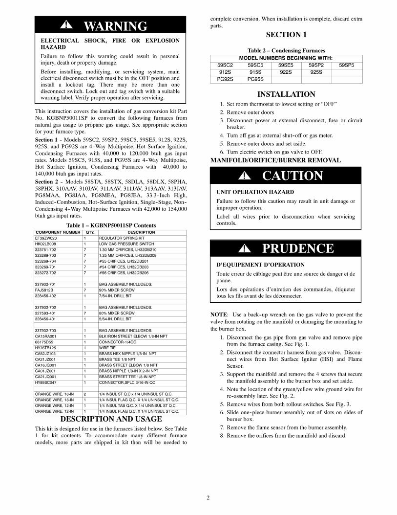
If the vent pipe passes between the inducer and burner assembly,or the furnace is a 14 3/16-in. (360 mm) wide casing, install theswitch as follows (See Fig 11.):
1. Remove the 1/8-in. NPT pipe plug from the gas valve inletpressure tap.
NOTE: Use pipe dope approved for use with Propane Gas.
NOTE: Tighten all fittings and the Low Gas Pressure Switchwith a small wrench. Do not over-tighten, check for gas leaksafter gas supply has been turned on.
FIRE AND EXPLOSION HAZARD
Failure to follow this warning could result in personal injury,death, and/or property damage.
NEVER test for gas leaks with an open flame. Use acommercially available soap solution made specifically forthe detection of leaks to check all connections. A fire orexplosion may result causing property damage, personalinjury or loss of life.
! WARNING
RISQUE D’EXPLOSION ET D’INCENDIE
Cet avertissement peut entraîner de la mort, des blessures et/oudes dégâts matériels.
Ne jamais examiner pour les fuites de gaz avec une flammevive. Utilisez plutôt un savon fait specifiquement pour ladétection des fuites de gaz pour verifier tous les connections.Un incendie ou une explosion peut entrainer des dommagesmatériels, des blessures ou la mort.
! AVERTISSEMENT
2. Apply pipe dope sparingly to the male threads of the1/8-in. black iron street elbow. Install the street elbow intothe gas valve inlet pressure tap. Point the open end of thestreet elbow toward you.
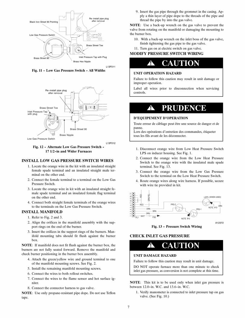
3. Apply pipe dope sparingly to the male threads of the1/8-in. brass street tee. Install the male end of the street teeas shown in Fig 12. One opening on the street tee shouldface you. The other opening should be parallel with theinlet of the gas valve.
4. Apply pipe dope sparingly to the male threads of the1/8-in. brass hex nipple. Install the hex nipple into theopen end of the brass street tee. See Fig 12. The hex nippleshould be parallel with the boss on the gas valve.
5. Install the open end of the brass street elbow on the end ofthe hex nipple. Tighten the street elbow so the malethreads of the elbow point away from you.
6. Apply pipe dope sparingly to the male threads of the1/8-in. brass street elbow. Install the Low Gas PressureSwitch on the male threads of the street elbow. Tightenswitch at hex fitting at base of switch. Do not use switchbody to tighten switch. Do not over-tighten switch.
7. The remaining opening on the brass street tee is the newgas valve inlet pressure tap. Install manometer fitting tothe open end of the brass street tee. Or if installation is tobe completed later, apply pipe dope to inlet pressure plugfrom gas valve and install in open end of brass street tee.
8. Check all fittings for leaks after gas supply has beenturned on.
Casings Wider Than 14 3/16-in. (360 mm)/Vent Does NotPass Between Inducer and Burner Assembly
1. If the vent pipe does not pass between the inducer andburner assembly, or the furnace is wider than a 14 3/16-in.(360 mm) wide casing, install the switch as follows (SeeFig 12.):
2. Remove the 1/8-in. NPT pipe plug from the gas valve inletpressure tap.
NOTE: Use pipe dope approved for use with Propane Gas.
7
Brass Street Tee
Brass Hex Nipple
Brass Street 90
Low Gas Pressure Switch
Black Iron Street 90 Pointing
Inlet Pressure Tap with Plug
Re install pipe plugafter removal
L13F011
Fig. 11 -- Low Gas Pressure Switch -- All Widths
L13F012
Fig. 12 -- Alternate Low Gas Pressure Switch --17 1/2--in and Wider Furnaces
INSTALL LOW GAS PRESSURE SWITCH WIRES1. Locate the orange wire in the kit with an insulated straight
female spade terminal and an insulated straight male ter-minal on the other end.
2. Connect the female terminal to a terminal on the Low GasPressure Switch.
3. Locate the orange wire in kit with an insulated straight fe-male spade terminal and an insulated female flag terminalon the other end.
4. Connect both straight female terminals of the orange wiresto the terminals on the Low Gas Pressure Switch.
INSTALL MANIFOLD1. Refer to Fig. 2 and 3.
2. Align the orifices in the manifold assembly with the sup-port rings on the end of the burner.
3. Insert the orifices in the support rings of the burners. Man-ifold mounting tabs should fit flush against the burnerbox.
NOTE: If manifold does not fit flush against the burner box, theburners are not fully seated forward. Remove the manifold andcheck burner positioning in the burner box assembly.
4. Attach the green/yellow wire and ground terminal to oneof the manifold mounting screws. See Fig. 2.
5. Install the remaining manifold mounting screws.
6. Connect the wires to both rollout switches.
7. Connect the wires to the flame sensor and hot surface ig-niter.
8. Connect the connector harness to gas valve.
NOTE: Use only propane-resistant pipe dope. Do not use Teflontape.
9. Insert the gas pipe through the grommet in the casing. Ap-ply a thin layer of pipe dope to the threads of the pipe andthread the pipe by into the gas valve.
NOTE: Use a back-up wrench on the gas valve to prevent thevalve from rotating on the manifold or damaging the mounting tothe burner box.
10. With a back-up wrench on the inlet boss of the gas valve,finish tightening the gas pipe to the gas valve.
11. Turn gas on at electric switch on gas valve.
MODIFY PRESSURE SWITCH WIRING
UNIT OPERATION HAZARD
Failure to follow this caution may result in unit damage orimproper operation.
Label all wires prior to disconnection when servicingcontrols.
CAUTION!
D’EQUIPEMENT D’OPERATION
Toute erreur de câblage peut être une source de danger et depanne.Lors des opérations d’entretien des commandes, étiquetertous les fils avant de les déconnecter.
PRUDENCE!
1. Disconnect orange wire from Low Heat Pressure SwitchLPS on inducer housing. See Fig. 1.
2. Connect the orange wire from the Low Heat PressureSwitch to the orange wire with the insulated male spadeterminal. See Fig. 13.
3. Connect the orange wire from the Low Gas PressureSwitch to the terminal on the Low Heat Pressure Switch.
4. Route orange wires along wire harness. If possible, securewith wire tie provided in kit.
A12372
Fig. 13 -- Pressure Switch Wiring
CHECK INLET GAS PRESSURE
UNIT DAMAGE HAZARD
Failure to follow this caution may result in unit damage.
DO NOT operate furnace more than one minute to checkinlet gas pressure, as conversion is not complete at this time.
CAUTION!
NOTE: This kit is to be used only when inlet gas pressure isbetween 12.0--in. W.C. and 13.6--in. W.C.
1. Verify manometer is connected to inlet pressure tap on gasvalve. (See Fig. 10.)
8
2. Turn on furnace power supply.
3. Turn gas supply manual shutoff valve to ON position.
FIRE, EXPLOSION, ELECTRICAL SHOCKHAZARD
Failure to follow this warning could result in personalinjury, death or property damage.
Gas supply MUST be shut off before disconnectingelectrical power and proceeding with conversion.
! WARNING
ELECTRICAL SHOCK, FIRE OR EXPLOSIONHAZARD
Failure to follow this warning could result in personalinjury, death or property damage.
Before installing, modifying, or servicing system, mainelectrical disconnect switch must be in the OFF position andinstall a lockout tag. There may be more than onedisconnect switch. Lock out and tag switch with a suitablewarning label. Verify proper operation after servicing.
! WARNING
4. Turn furnace gas valve switch to ON position.
5. Jumper R--W thermostat connections on control.
6. When main burners ignite, confirm inlet gas pressure isbetween 12.0--in. W.C. and 13.6--in. W.C.
7. Remove jumper across R--W thermostat connections toterminate call for heat.
8. Turn furnace gas valve switch to OFF position.
CHECK FURNACE AND MAKE ADJUSTMENTS
FIRE AND EXPLOSION HAZARD
Failure to follow this warning could result in personal injury,death, and/or property damage.
NEVER test for gas leaks with an open flame. Use acommercially available soap solution made specifically forthe detection of leaks to check all connections. A fire orexplosion may result causing property damage, personalinjury or loss of life.
! WARNING
RISQUE D’EXPLOSION ET D’INCENDIE
Cet avertissement peut entraîner de la mort, des blessures et/oudes dégâts matériels.
Ne jamais examiner pour les fuites de gaz avec une flammevive. Utilisez plutôt un savon fait specifiquement pour ladétection des fuites de gaz pour verifier tous les connections.Un incendie ou une explosion peut entrainer des dommagesmatériels, des blessures ou la mort.
! AVERTISSEMENT
1. Be sure main gas and electric supplies to furnace are off.
2. Remove 1/8-in. (3 mm) pipe plug from manifold pressuretap on downstream side of gas valve.
3. Attach manometer to manifold pressure tap on gas valve.(see Fig. 10.)
4. Turn gas supply manual shutoff valve to ON position.
5. Turn furnace gas valve switch to ON position.
6. Check all threaded pipe connections for gas leaks.
7. Turn on furnace power supply.
GAS INPUT RATE INFORMATIONThe gas input rate for propane is the same as for natural gas. Seefurnace rating plate (see Fig. 5) for input rate. The input rate forpropane is determined by manifold pressure and orifice size.
The gas valve must be set for Low Heat first and then set for HighHeat on 2--stage and variable--speed furnaces. Furnace gas inputrate on rating plate is for installations at altitudes up to 2000 ft.(610 M).
In the U.S.A.; the input rating for altitudes above 2000 ft.(610M) must be reduced by 2 percent for each 1000 ft. (305 M)above sea level.
In Canada; the input rating must be derated by 5 percent foraltitudes of 2000 ft. (610 M) to 4500 ft. (1372 M) above sealevel.
The Conversion Kit Rating Plate accounts for high altitudederate.
SET GAS INPUT RATE1. Jumper R and W thermostat connections to call for heat.
(See Fig. 14.)
2. Check manifold orifices for gas leaks when main burnersignite.
3. Adjust gas manifold pressure.
4. Remove cap that conceals gas valve regulator adjustmentscrew.
5. Turn adjusting screw counterclockwise (out) to decreasemanifold pressure or clockwise (in) to increase manifoldpressure.
6. Replace gas valve regulator seal cap.
7. Verify manifold pressure is correct.
NOTE: Gas valve regulator seal cap MUST be in place whenchecking input rate. When correct input is obtained, main burnerflame should be clear blue, almost transparent (See Fig. 15). Besure regulator seal cap is in place when finished.
8. Remove jumper across R and W thermostat connections toterminate call for heat.
9. Turn furnace gas valve control switch or control knob toOFF position.
10. Turn off furnace power supply.
11. Remove manometer and reinstall manifold pressure tapplug.
12. Turn furnace gas--valve switch to ON position.
13. Turn on furnace power supply.
14. Set room thermostat to call for heat.
15. Check pressure tap plug for gas leaks when main burnersignite.
16. Check for correct burner flame.
17. Observe unit operation through 2 complete heating cycles.
18. See Sequence of Operation in furnace Installation, Start--Up, and Operating Instructions.
19. Set room thermostat to desired temperature.
20. After making the required manifold pressure adjustments,check and adjust the furnace temperature rise per the fur-nace installation instructions.

9
TWINNING AND/ORCOMPONENT TESTTERMINAL
PL1 − LOW VOLTAGE MAINHARNESS CONNECTOR
TRANSFORMER 24VACCONNECTIONS
EAC TERMINAL(115 VAC 1.0 AMP MAX.)
SEC-2
115−VAC (L2)NEUTRALCONNECTIONS
24−V THERMOSTATTERMINALS
HUMIDIFIER TERMINAL(24−VAC 0.5 AMP MAX)
3−AMP FUSE
LEDOPERATION &DIAGNOSTICLIGHT
SEC-1
BLOWER SPEEDSELECTION TERMINALS
BL−1 PR-1
COM
HEAT
COOL
FAN
SPARE2
SPARE1
Y1
DH
UM
BLOWER OFF-DELAY
120 180
90 150
24V M
TR
TAP
S
115 VAC (L1)INPUT
L1 IND
PL-2 HOT SURFACEIGNITOR (HSI) &INDUCER MOTOR(IND) CONNECTOR
HUM
EAC-1
HSI
PL
-2
PL1
EAC-2
Com24V
L2
A11391
Fig. 14 -- Single--Stage Furnace Control
Burner Flame
Burner
ManifoldA11461
Fig. 15 -- Burner Flame
CHECK LOW GAS PRESSURE SWITCHThe newly installed low gas pressure switch is a safety deviceused to guard against adverse burner operating characteristics thatcan result from low gas supply pressure. Switch opens at not lessthan 7.2 in. W.C. and closes at not greater than 10.2 in. W.C.
This switch also prevents operation when the propane tank levelis low which can result in gas with a high concentration ofimpurities, additives, and residues that have settled to the bottomof the tank. Operation under these conditions can cause harm tothe heat exchanger system. This normally open switch closeswhen gas is supplied to gas valve under normal operatingpressure.
The closed switch completes control circuit. Should aninterruption or reduction in gas supply occur, the gas pressure atswitch drops below low gas pressure switch setting, and switchopens. Any interruption in control circuit (in which low gaspressure switch is wired) quickly closes gas valve and stops gasflow to burners. When normal gas pressure is restored, the systemmust be electrically reset to re--establish normal heating operation.
Before leaving installation, observe unit operation through 2complete heating cycles. During this time, turn gas supply to gasvalve off just long enough to completely extinguish burner flame,then instantly restore full gas supply. To ensure proper low gaspressure switch operation, observe that there is no gas supply toburners until after hot surface igniter begins glowing.
LABEL APPLICATION1. Fill in Conversion Responsibility Label 339852--205 (see
Fig. 32) and apply to blower door of furnace as shown.Date, name, and address of organization making this con-version are required.
2. Attach Conversion Rating Plate Label 339852--201 to out-er door of furnace.
3. Apply Gas Control Conversion Label to gas valve: Forsingle--stage gas valve apply label 339852--202 to gasvalve. (Do not use 339852--203, which is similar) Checkfor correct normal operating sequence of the ignition sys-tem as described in furnace Installation, Start--Up, and Op-erating Instructions.
4. Replace control access door, blower door and outer doorof furnace.
CHECKOUT1. Observe unit operation through 2 complete heating cycles.
2. See Sequence of Operation in furnace Installation, Start--Up, and Operating Instructions.
3. Set room thermostat to desired temperature.

10
SECTION 2
Table 3 – Non--condensing FurnacesMODEL NUMBERS BEGINNING WITH:
58STA 58STX 58DLA 58DLX 58PHA 58PHX310AAV 310JAV 311AAV 311JAV 313AAV 313JAVPG8MAA PG8JAA PG8MEA PG8JEA
INSTALLATION
FIRE, EXPLOSION, ELECTRICAL SHOCK ANDCARBON MONOXIDE POISONING HAZARD
Failure to follow instructions could result in personal injury,death or property damage.
Improper installation, adjustment, alteration, service,maintenance, or use can cause carbon monoxide poisoning,explosion, fire, electrical shock, or other conditions, whichcould result in personal injury or death. Consult yourdistributor or branch for information or assistance. Thequalified installer or agency must use onlyfactory--authorized kits or accessories when servicing thisproduct.
! WARNING
FIRE, EXPLOSION, ELECTRICAL SHOCK, ANDCARBON MONOXIDE POISONING HAZARD
Failure to follow this warning could result in personalinjury or death.
This conversion kit shall be installed by a qualified serviceagency in accordance with the manufacturer’s instructionsand all applicable codes and requirements of the authorityhaving jurisdiction. If the information in these instructionsis not followed exactly, a fire, explosion, or production ofcarbon monoxide could result causing property damage,personal injury, or loss of life. The qualified service agencyis responsible for the proper installation of this furnace withthis kit. The installation is not proper and complete until theoperation of the converted appliance is checked as specifiedin the manufacturer’s instructions supplied with the kit.
! WARNING
LE FEU, L’EXPLOSION, CHOC ELECTRIQUE,ET MONOXYDE DE CARBONEEMPOISONNER
Cette trousse de conversion doit être installée par un servied’entretien qualifié, selon les instructions du fabricant etselon toutes les exigences et tous les codes pertinents del’autorité compétente. Assurezvous de bien suivre lesinstructions dans cette notice pour réduire au minimum lerisque d’incendie, d’explosion ou la production demonoxyde de carbone pouvant causer des dommagesmatériels, de blessure ou la mort. Le service d’entretienqualifié est responsable de l’installation de cette trousse.L’installation n’est pas adéquate ni complète tant que le bonfonctionnement de l’appereil converti n’a pas été vérfiéselon les instructions du fabricant fornies avec la trousse.
! AVERTISSEMENT
FIRE, EXPLOSION, ELECTRICAL SHOCKHAZARD
Failure to follow this warning could result in personalinjury, death or property damage.
Gas supply MUST be shut off before disconnectingelectrical power and proceeding with conversion.
! WARNING
1. Set room thermostat to lowest setting or “OFF”.
2. Remove outer doors.
3. Disconnect power at external disconnect, fuse or circuitbreaker.
4. Turn off gas at external shut-off or gas meter.
5. Remove outer doors and set aside.
6. Turn electric switch on gas valve to OFF.
FIRE, EXPLOSION, ELECTRICAL SHOCKHAZARD
Failure to follow this warning could result in personalinjury, death or property damage.
Gas supply MUST be shut off before disconnectingelectrical power and proceeding with conversion.
! WARNING
ELECTRICAL SHOCK, FIRE OR EXPLOSIONHAZARD
Failure to follow this warning could result in personalinjury, death or property damage.
Before installing, modifying, or servicing system, mainelectrical disconnect switch must be in the OFF position andinstall a lockout tag. There may be more than onedisconnect switch. Lock out and tag switch with a suitablewarning label. Verify proper operation after servicing.
! WARNING
MANIFOLD/ORIFICE/BURNER REMOVAL
Attach Green/Yellowground wire here
Manifold Assy Sensor FlameClip, Harness
Burner Assy
Burner Support Assy
Switch, Temp (2)
Ignitor
Bracket Ignitor
A11390
Fig. 16 -- 80% Burner
11
Gas Valve
Screw (2)
Attach Green/Yellowground wire here
Orifice
Manifold
A11395
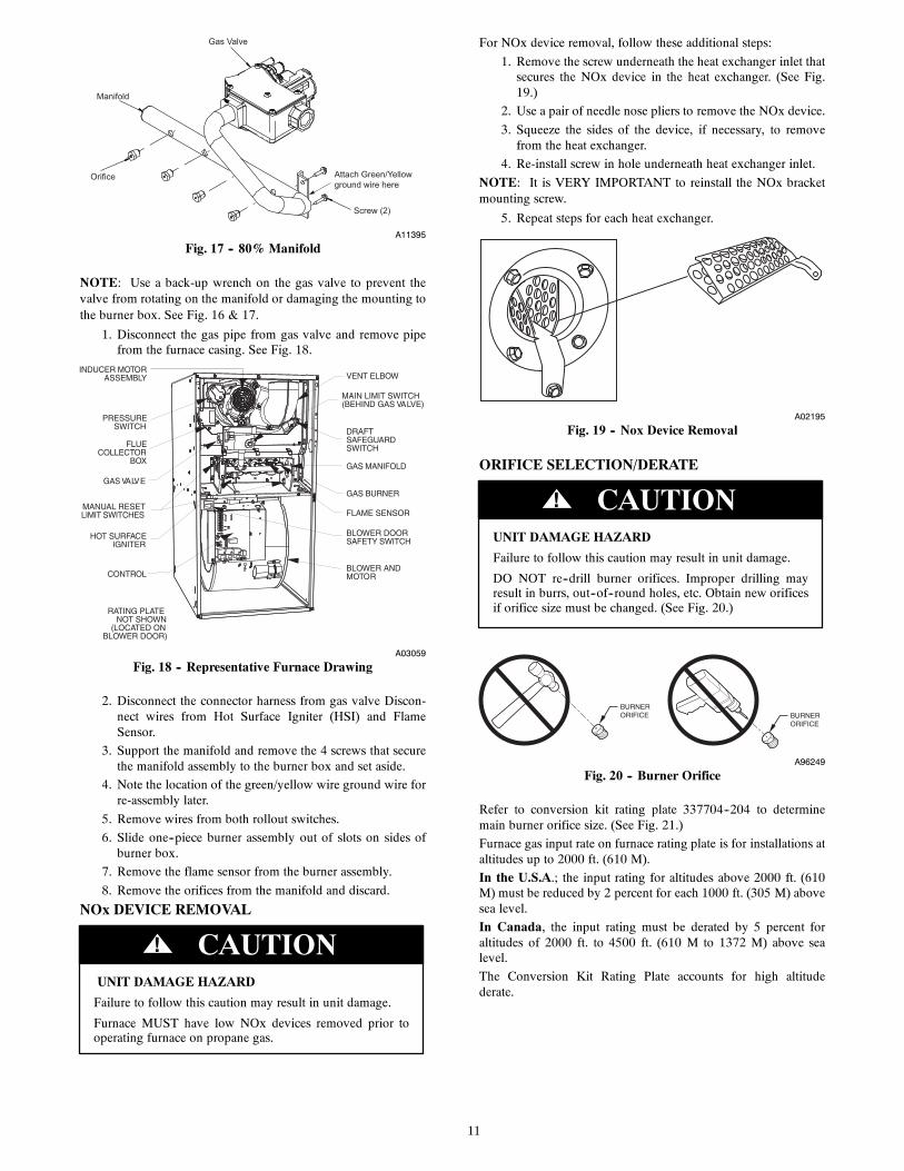
Fig. 17 -- 80% Manifold
NOTE: Use a back-up wrench on the gas valve to prevent thevalve from rotating on the manifold or damaging the mounting tothe burner box. See Fig. 16 & 17.
1. Disconnect the gas pipe from gas valve and remove pipefrom the furnace casing. See Fig. 18.
A03059
Fig. 18 -- Representative Furnace Drawing
2. Disconnect the connector harness from gas valve Discon-nect wires from Hot Surface Igniter (HSI) and FlameSensor.
3. Support the manifold and remove the 4 screws that securethe manifold assembly to the burner box and set aside.
4. Note the location of the green/yellow wire ground wire forre-assembly later.
5. Remove wires from both rollout switches.
6. Slide one--piece burner assembly out of slots on sides ofburner box.
7. Remove the flame sensor from the burner assembly.
8. Remove the orifices from the manifold and discard.
NOx DEVICE REMOVAL
UNIT DAMAGE HAZARD
Failure to follow this caution may result in unit damage.
Furnace MUST have low NOx devices removed prior tooperating furnace on propane gas.
CAUTION!
For NOx device removal, follow these additional steps:
1. Remove the screw underneath the heat exchanger inlet thatsecures the NOx device in the heat exchanger. (See Fig.19.)
2. Use a pair of needle nose pliers to remove the NOx device.
3. Squeeze the sides of the device, if necessary, to removefrom the heat exchanger.
4. Re-install screw in hole underneath heat exchanger inlet.
NOTE: It is VERY IMPORTANT to reinstall the NOx bracketmounting screw.
5. Repeat steps for each heat exchanger.
A02195
Fig. 19 -- Nox Device Removal
ORIFICE SELECTION/DERATE
UNIT DAMAGE HAZARD
Failure to follow this caution may result in unit damage.
DO NOT re--drill burner orifices. Improper drilling mayresult in burrs, out--of--round holes, etc. Obtain new orificesif orifice size must be changed. (See Fig. 20.)
CAUTION!
BURNER ORIFICE BURNER
ORIFICE
A96249
Fig. 20 -- Burner Orifice
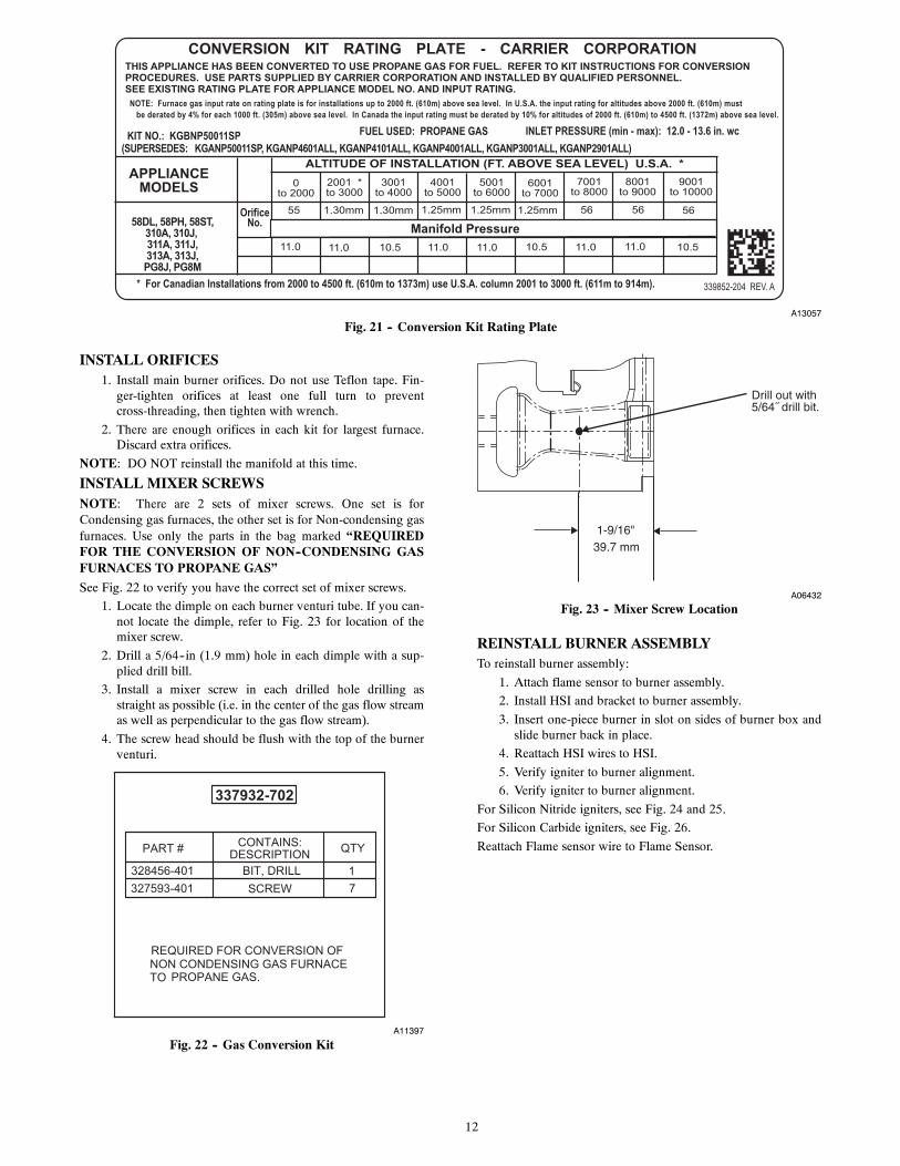
Refer to conversion kit rating plate 337704--204 to determinemain burner orifice size. (See Fig. 21.)
Furnace gas input rate on furnace rating plate is for installations ataltitudes up to 2000 ft. (610 M).
In the U.S.A.; the input rating for altitudes above 2000 ft. (610M) must be reduced by 2 percent for each 1000 ft. (305 M) abovesea level.
In Canada, the input rating must be derated by 5 percent foraltitudes of 2000 ft. to 4500 ft. (610 M to 1372 M) above sealevel.
The Conversion Kit Rating Plate accounts for high altitudederate.
12
A13057
Fig. 21 -- Conversion Kit Rating Plate
INSTALL ORIFICES1. Install main burner orifices. Do not use Teflon tape. Fin-
ger-tighten orifices at least one full turn to preventcross-threading, then tighten with wrench.
2. There are enough orifices in each kit for largest furnace.Discard extra orifices.
NOTE: DO NOT reinstall the manifold at this time.
INSTALL MIXER SCREWSNOTE: There are 2 sets of mixer screws. One set is forCondensing gas furnaces, the other set is for Non-condensing gasfurnaces. Use only the parts in the bag marked “REQUIREDFOR THE CONVERSION OF NON--CONDENSING GASFURNACES TO PROPANE GAS”
See Fig. 22 to verify you have the correct set of mixer screws.
1. Locate the dimple on each burner venturi tube. If you can-not locate the dimple, refer to Fig. 23 for location of themixer screw.
2. Drill a 5/64--in (1.9 mm) hole in each dimple with a sup-plied drill bill.
3. Install a mixer screw in each drilled hole drilling asstraight as possible (i.e. in the center of the gas flow streamas well as perpendicular to the gas flow stream).
4. The screw head should be flush with the top of the burnerventuri.
A11397
Fig. 22 -- Gas Conversion Kit
A06432
Fig. 23 -- Mixer Screw Location
REINSTALL BURNER ASSEMBLYTo reinstall burner assembly:
1. Attach flame sensor to burner assembly.
2. Install HSI and bracket to burner assembly.
3. Insert one-piece burner in slot on sides of burner box andslide burner back in place.
4. Reattach HSI wires to HSI.
5. Verify igniter to burner alignment.
6. Verify igniter to burner alignment.
For Silicon Nitride igniters, see Fig. 24 and 25.
For Silicon Carbide igniters, see Fig. 26.
Reattach Flame sensor wire to Flame Sensor.

13
9/32”7.1mm
5/16”7.9mm
A05025
Fig. 24 -- Igniter Position -- Side View
1-7/8(47.6 mm)
A05026
Fig. 25 -- Igniter Position -- Top View
A93347
Fig. 26 -- Silicon Carbide Igniters
CONVERT GAS VALVE
UNIT DAMAGE HAZARD
Failure to follow this caution may result in unit damage
The gas valve must be converted and pre--adjusted beforeoperating on propane gas. If left this way, sooting andcorrosion will occur leading to early heat exchanger failure.
CAUTION!
FIRE, EXPLOSION, ELECTRICAL SHOCKHAZARD
Failure to follow this warning could result in personalinjury, death or property damage.
Gas supply MUST be shut off before disconnectingelectrical power and proceeding with conversion.
! WARNING
ELECTRICAL SHOCK, FIRE OR EXPLOSIONHAZARD
Failure to follow this warning could result in personalinjury, death or property damage.
Before installing, modifying, or servicing system, mainelectrical disconnect switch must be in the OFF position andinstall a lockout tag. There may be more than onedisconnect switch. Lock out and tag switch with a suitablewarning label. Verify proper operation after servicing.
! WARNING
1. Refer to Fig. 27.
2. Be sure gas and electrical supplies to furnace are off.
3. Remove caps that conceal adjustment screws for the gasvalve regulators. (See Fig. 27.)
4. Remove the regulator adjustment screw.
5. Remove the regulator springs (silver).
6. Install the propane gas regulator springs (white).
7. Install the regulator adjustment screws.
8. Turn the adjusting screw clockwise (in) 8.5 full turns. Thiswill increase the manifold pressure closer to the propaneset point. (See Fig. 27.)
9. Do not install regulator seal caps at this time.

14
ON/OFF Switch
Regulator Seal Cap
Regulator Adjustment underRegulator Seal Cap
1/2” NPT Outlet
1/8” NPT ManifoldPressure Tap
1/8” NPT InletPressure Tap
1/2” NPT Inlet
SINGLE-STAGERegulator Spring
Propane - White 8.5 turns
Natural Gas - Silver 8.5 turns
Regulator Adjustment
Screw
Regulator Seal Cap
A13048
Fig. 27 -- Single Stage Gas Valve
A05071
Fig. 28 -- Redundant Auto Gas Valve
REGULATOR SPRING(PROPANE – WHITE, 6 TURNS NATURAL – SILVER, 10 TURNS)
REGULATORADJUSTMENTSCREW
REGULATORSEAL CAP
GAS PRESSUREREGULATORADJUSTMENTINLET
PRESSURE TAP
ON ANDOFF SWITCH
MANIFOLDPRESSURE TAP
A01073
Fig. 29 -- Single--Solenoid Redundant Auto Gas Valve
INSTALL MANIFOLD1. Refer to Fig. 16 &17.
2. Align the orifices in the manifold assembly with the sup-port rings on the end of the burner.
3. Insert the orifices in the support rings of the burners. Man-ifold mounting tabs should fit flush against the burnerbox.
NOTE: If manifold does not fit flush against the burner box, theburners are not fully seated forward. Remove the manifold andcheck burner positioning in the burner box assembly.
4. Attach the green/yellow wire and ground terminal to oneof the manifold mounting screws.
5. Install the remaining manifold mounting screws.
6. Connect the wires to both rollout switches.
7. Connect the wires to the flame sensor and hot surface ig-niter.
8. Connect the connector harness to gas valve.
NOTE: Use only propane-resistant pipe dope. Do not use Teflontape.
9. Insert the gas pipe through the grommet in the casing. Ap-ply a thin layer of pipe dope to the threads of the pipe andthread the pipe by into the gas valve.
NOTE: Use a back-up wrench on the gas valve to prevent thevalve from rotating on the manifold or damaging the mounting tothe burner box.
10. With a back-up wrench on the inlet boss of the gas valve,finish tightening the gas pipe to the gas valve.
11. Turn gas on at electric switch on gas valve.
INSTALL LOW GAS PRESSURE SWITCH
FIRE, EXPLOSION, ELECTRICAL SHOCKHAZARD
Failure to follow this warning could result in personalinjury, death or property damage.
Gas supply MUST be shut off before disconnectingelectrical power and proceeding with conversion.
! WARNING
ELECTRICAL SHOCK, FIRE OR EXPLOSIONHAZARD
Failure to follow this warning could result in personalinjury, death or property damage.
Before installing, modifying, or servicing system, mainelectrical disconnect switch must be in the OFF position andinstall a lockout tag. There may be more than onedisconnect switch. Lock out and tag switch with a suitablewarning label. Verify proper operation after servicing.
! WARNING
NOTE: Use propane-gas-resistant pipe dope on all connectionsto prevent gas leaks. DO NOT use Teflon tape. See Fig. 30.
1. Be sure main gas and electric supplies to furnace are off.
2. Remove 1/8-in. (3 mm) pipe plug from inlet pressure tapon gas valve. DO NOT DISCARD 1/8-in. (3 mm) PLUG.
3. Apply pipe dope sparingly to one end of 1/8-in. (3 mm) x2--in. (50.8 mm) brass nipple (provided in kit) and installthe doped end in 1/8-in. (3 mm) tapped opening in gasvalve inlet pressure-tap. Tighten fitting with a smallwrench.
4. Apply pipe dope sparingly to opposite end of the 1/8-in.(3 mm) x 2--in. (50.8 mm) brass coupling (provided inkit). Install the female end of the female x female x maletee on the brass coupling.
5. Tighten tee finger tight. Use a small open-end wrench forfinal tightening. The male end of the tee should be facingyou.

15
6. Apply pipe dope sparingly to male end of brass tee.
7. Install propane low gas pressure switch (provided in kit)on male end of the female x female x male tee.
8. Tighten switch finger tight.
9. Use a small open-end wrench on base of pressure switchfor final tightening. The contacts of the LGPS should bepointing toward the inducer motor when complete.
10. The remaining opening on the brass street tee is the newgas valve inlet pressure tap.
11. Install manometer fitting to the open end of the brass streettee. Or if installation is to be completed later, apply pipedope to inlet pressure plug from gas valve and install inopen end of brass street tee.
12. Check all fittings for leaks after gas supply has beenturned on.
FIRE AND EXPLOSION HAZARD
Failure to follow this warning could result in personal injury,death, and/or property damage.
NEVER test for gas leaks with an open flame. Use acommercially available soap solution made specifically forthe detection of leaks to check all connections. A fire orexplosion may result causing property damage, personalinjury or loss of life.
! WARNING
RISQUE D’EXPLOSION ET D’INCENDIE
Cet avertissement peut entraîner de la mort, des blessures et/oudes dégâts matériels.
Ne jamais examiner pour les fuites de gaz avec une flammevive. Utilisez plutôt un savon fait specifiquement pour ladétection des fuites de gaz pour verifier tous les connections.Un incendie ou une explosion peut entrainer des dommagesmatériels, des blessures ou la mort.
! AVERTISSEMENT
2” Brass Nipple
Low GasPressure Switch
Female x Female x Male Tee
1/8” NPT Pipe PlugFor inlet pressure tap
A11398
Fig. 30 -- 80% Low Gas Pressure Switch
MODIFY PRESSURE SWITCH WIRING
UNIT OPERATION HAZARD
Failure to follow this caution may result in unit damage orimproper operation.
Label all wires prior to disconnection when servicingcontrols.
CAUTION!
D’EQUIPEMENT D’OPERATION
Toute erreur de câblage peut être une source de danger et depanne.Lors des opérations d’entretien des commandes, étiquetertous les fils avant de les déconnecter.
PRUDENCE!
Refer to Fig. 31.
1. Locate the orange wire in the kit with an insulated straightfemale spade terminal and an insulated straight male ter-minal on the other end.
2. Connect the female terminal to a terminal on the Low GasPressure Switch.
3. Locate the orange wire in the kit with an insulated straightfemale spade terminal and an insulated female flag termin-al on the other end.
4. Connect both straight female terminals of the orange wiresto the terminals on the Low Gas Pressure Switch.
5. Disconnect yellow wire from Low Heat Pressure SwitchLPS on inducer housing.
6. Connect the yellow wire from the Low Heat PressureSwitch to the orange wire with the insulated male spadeterminal.
7. Connect the orange wire from the Low Gas PressureSwitch to the terminal on the Low Heat Pressure Switch.
8. Route orange wires along wire harness. If possible, securewith wire tie provided in kit.
A11394
Fig. 31 -- 80% Pressure Switch Wiring

16
CHECK INLET GAS PRESSURE
UNIT DAMAGE HAZARD
Failure to follow this caution may result in unit damage.
DO NOT operate furnace more than one minute to checkinlet gas pressure, as conversion is not complete at this time.
CAUTION!
NOTE: This kit is to be used only when inlet gas pressure isbetween 12.0--in. W.C. and 13.6--in. W.C.
1. Verify manometer is connected to inlet pressure tap on gasvalve.
2. Turn on furnace power supply.
3. Turn gas supply manual shutoff valve to ON position.
4. Turn furnace gas valve switch to ON position.
5. Jumper R--W thermostat connections on control.
6. When main burners ignite, confirm inlet gas pressure isbetween 12.0--in. W.C. and 13.6--in. W.C.
7. Remove jumper across R--W thermostat connections toterminate call for heat.
8. Turn furnace gas valve switch to OFF position.
9. Turn gas supply manual shutoff valve to OFF position.
10. Turn off furnace power supply.
11. Remove manometer.
12. Apply pipe dope sparingly to end of inlet gas pipe plugand install into unused end of 1/8 in. tee. Use a smallback--up wrench on tee when tightening gas inlet pipeplug.
CHECK FURNACE AND MAKE ADJUSTMENTS
FIRE AND EXPLOSION HAZARD
Failure to follow this warning could result in personal injury,death, and/or property damage.
NEVER test for gas leaks with an open flame. Use acommercially available soap solution made specifically forthe detection of leaks to check all connections. A fire orexplosion may result causing property damage, personalinjury or loss of life.
! WARNING
RISQUE D’EXPLOSION ET D’INCENDIE
Cet avertissement peut entraîner de la mort, des blessures et/oudes dégâts matériels.
Ne jamais examiner pour les fuites de gaz avec une flammevive. Utilisez plutôt un savon fait specifiquement pour ladétection des fuites de gaz pour verifier tous les connections.Un incendie ou une explosion peut entrainer des dommagesmatériels, des blessures ou la mort.
! AVERTISSEMENT
FIRE, EXPLOSION, ELECTRICAL SHOCKHAZARD
Failure to follow this warning could result in personalinjury, death or property damage.
Gas supply MUST be shut off before disconnectingelectrical power and proceeding with conversion.
! WARNING
ELECTRICAL SHOCK, FIRE OR EXPLOSIONHAZARD
Failure to follow this warning could result in personalinjury, death or property damage.
Before installing, modifying, or servicing system, mainelectrical disconnect switch must be in the OFF position andinstall a lockout tag. There may be more than onedisconnect switch. Lock out and tag switch with a suitablewarning label. Verify proper operation after servicing.
! WARNING
1. Be sure main gas and electric supplies to furnace are off.
2. Remove 1/8-in. (3 mm) pipe plug from manifold pressuretap on downstream side of gas valve.
3. Attach manometer to manifold pressure tap on gas valve.See Fig. 27, 28 & 29.
4. Turn gas supply manual shutoff valve to ON position.
5. Turn furnace gas valve switch to ON position.
6. Check all threaded pipe connections for gas leaks.
7. Turn on furnace power supply.
GAS INPUT RATE INFORMATIONThe gas input rate for propane is the same as for natural gas. Seefurnace rating plate for input rate. The input rate for propane isdetermined by manifold pressure and orifice size.
The gas valve must be set for Low Heat first and then set for Highheat on 2--stage and variable--speed furnaces. Furnace gas inputrate on rating plate is for installations at altitudes up to 2000 ft.(610 M).
In the U.S.A.; the input rating for altitudes above 2000 ft.(610M) must be reduced by 2 percent for each 1000 ft. (305 M)above sea level.
In Canada; the input rating must be derated by 5 percent foraltitudes of 2000 ft. (610 M) to 4500 ft. (1372 M) above sealevel.
The Conversion Kit Rating Plate accounts for high altitudederate.
SET GAS INPUT RATE1. Jumper R and W thermostat connections to call for heat.
(See Fig. 14.)
2. Check manifold orifices for gas leaks when main burnersignite.
3. Adjust gas manifold pressure. Refer to conversion kit rat-ing plate 339852--204, Fig. 21.
4. Turn adjusting screw counterclockwise (outwards) to de-crease manifold pressure or clockwise (inwards) to in-crease manifold pressure.
17
NOTE: Gas valve regulator seal cap MUST be in place whenchecking input rate.
5. When correct input is obtained,main burner flame shouldbe clear blue, almost transparent. Be sure regulator sealcap is in place when finished. See Fig. 15.
6. Remove jumper across R and W thermostat connections toterminate call for heat.
7. Turn furnace gas valve control switch or control knob toOFF position.
8. Turn off furnace power supply.
9. Remove manometer and replace manifold pressure tapplug.
NOTE: Use propane--gas--resistant pipe dope to prevent gasleaks. DO NOT use Teflon tape.
10. Turn furnace gas valve control switch or control knob toON position.
11. Turn on furnace power supply. Set room thermostat to callfor heat.
12. Check manifold pressure tap plug for gas leaks when mainburners ignite.
13. Observe unit operation through 2 complete heating cycles.
14. See Sequence of Operation in furnace Installation, Start--up and Operating Instructions.
15. Set room thermostat to desired temperature.
After making the required manifold pressure adjustments, checkand adjust the furnace temperature rise per the furnace installationinstructions.
CHECK LOW GAS PRESSURE SWITCHThe newly installed low gas pressure switch is a safety deviceused to guard against adverse burner operating characteristics thatcan result from low gas supply pressure. Switch opens at not lessthan 7.2 in. W.C. and closes at not greater than 10.2 in. W.C.
This switch also prevents operation when the propane tank levelis low which can result in gas with a high concentration ofimpurities, additives, and residues that have settled to the bottomof the tank. Operation under these conditions can cause harm tothe heat exchanger system. This normally open switch closeswhen gas is supplied to gas valve under normal operatingpressure.
The closed switch completes control circuit. Should aninterruption or reduction in gas supply occur, the gas pressure atswitch drops below low gas pressure switch setting, and switchopens. Any interruption in control circuit (in which low gaspressure switch is wired) quickly closes gas valve and stops gasflow to burners. When normal gas pressure is restored, the systemmust be electrically reset to re--establish normal heating operation.
Before leaving installation, observe unit operation through 2complete heating cycles. During this time, turn gas supply to gasvalve off just long enough to completely extinguish burner flame,then instantly restore full gas supply. To ensure proper low gaspressure switch operation, observe that there is no gas supply toburners until after hot surface igniter begins glowing.
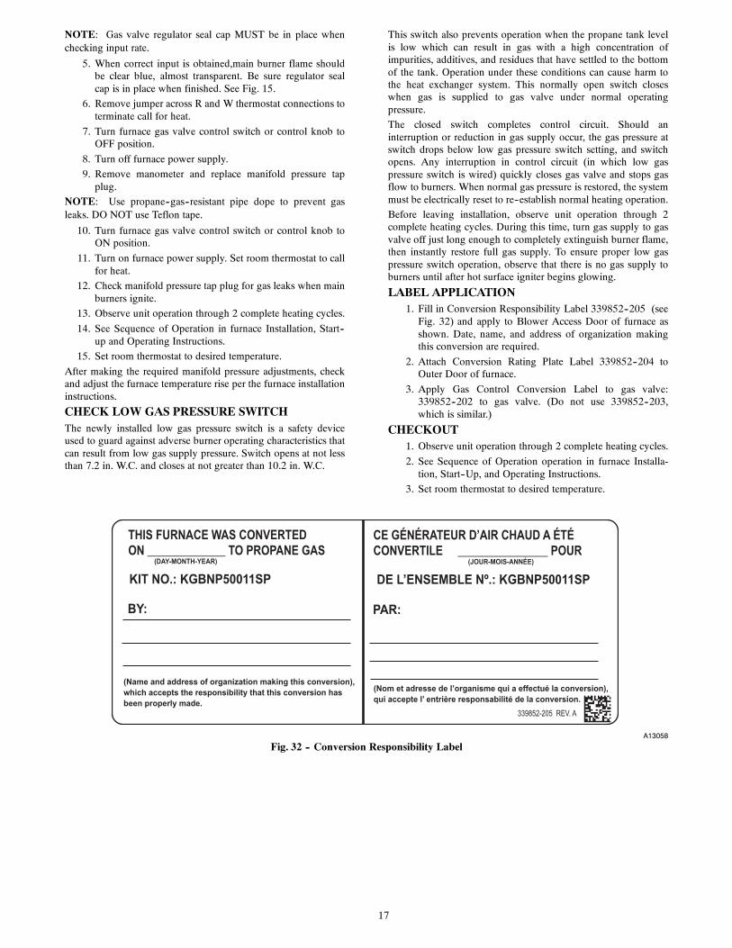
LABEL APPLICATION1. Fill in Conversion Responsibility Label 339852--205 (see
Fig. 32) and apply to Blower Access Door of furnace asshown. Date, name, and address of organization makingthis conversion are required.
2. Attach Conversion Rating Plate Label 339852--204 toOuter Door of furnace.
3. Apply Gas Control Conversion Label to gas valve:339852--202 to gas valve. (Do not use 339852--203,which is similar.)
CHECKOUT1. Observe unit operation through 2 complete heating cycles.
2. See Sequence of Operation operation in furnace Installa-tion, Start--Up, and Operating Instructions.
3. Set room thermostat to desired temperature.
A13058
Fig. 32 -- Conversion Responsibility Label

18
Copyright 2013 CAC / BDP D 7310 W. Morris St. D Indianapolis, IN 46231
Manufacturer reserves the right to change, at any time, specifications and designs without notice and without obligations.
Catalog No: AG---KGBNP1SP---01
Replaces: AG--KGANP1SP--02
Edition Date: 03/13