Product Configuration and Product Family Modelling€¦ · Product Configuration and Product Family...
27
1 Product Configuration and Product Family Modelling Kaj A. Jørgensen Associate Professor at Department of Production, Aalborg University October 2009 ABSTRACT In the last few years the demand for individualised products has increased and, as a result, product configuration has become more interesting. In this paper, fundamental concepts of product configuration are introduced. Furthermore, a methodology for modelling configurable products is presented. KEYWORDS Mass customisation, product configuration, product model, product family model, product functionality, and constrained-based configurator. 1 Introduction In the past century, production has changed from craftsmanship to mass production. When mass production was introduced by Henry Ford, the customers had no longer the same opportunity to influence on the composition of the product, which Henry Ford's famous quotation clearly states: ”Your car can have any colour you want, as long as it’s black”. At many companies, who in the last few years have performed mass production, a demand for customised products is clearly registered. These companies are aware that the market segments cannot be regarded homogeneous; the needs vary from customer to customer and products have to differ equally. So, many companies can find a potential in greater focus on the customers and to use this as a strategic opportunity to establish a competitive advantage.
Transcript of Product Configuration and Product Family Modelling€¦ · Product Configuration and Product Family...

1
Product Configuration and Product Family Modelling
Kaj A. Jørgensen
Associate Professor at Department of Production, Aalborg University
October 2009
ABSTRACT
In the last few years the demand for individualised products has increased and, as a result, product configuration has become more interesting. In this paper, fundamental concepts of product configuration are introduced. Furthermore, a methodology for modelling configurable products is presented.
KEYWORDS
Mass customisation, product configuration, product model, product family model, product functionality, and constrained-based configurator.
1 Introduction In the past century, production has changed from craftsmanship to mass production. When mass production was introduced by Henry Ford, the customers had no longer the same opportunity to influence on the composition of the product, which Henry Ford's famous quotation clearly states: ”Your car can have any colour you want, as long as it’s black”.
At many companies, who in the last few years have performed mass production, a demand for customised products is clearly registered. These companies are aware that the market segments cannot be regarded homogeneous; the needs vary from customer to customer and products have to differ equally. So, many companies can find a potential in greater focus on the customers and to use this as a strategic opportunity to establish a competitive advantage.

2
The combination of mass production and the capability to offer customised products is termed mass customisation [Pine, 1993]. As shown in figure 1, the aim is that mass customisation should take the benefits from both one-of-a-kind production and mass production with respect to customisation and production volume. In order to reach this goal, a considerable readiness has to be developed. The products have to be designed for this and the production must be well prepared.
High
Low
HighLow
Customisation
Number ofproduced units
Massproduction
MassCustomisation
One-of-a-kind
Batch
Figure 1 Three production forms positioned regarding customisation and production volume.
Mass Customisation (MC) was initiated more than one decade ago as a research topic with Davis’ publication “From Future Perfect: Mass Customisation” [Davis, 1989], presenting how products and services could be realised as a one-of-a-kind manufacture on a large scale. Davis also presented the idea that the customisation could be done at various points in the supply chain. In 1993, Pine published a major contribution to the mass customisation literature: “Mass Customization: The new Frontier in Business Competition” [Pine, 1993], [Pine et al., 1993], which was an extensive study of how American enterprises during the seventies and eighties had been overrun by the efficient Japanese manufacturers, which could produce at lower costs and higher quality. Since its introduction, MC has called for a change of paradigm in manufacturing and several companies have recognised the need for mass customisation. Much effort has been put into identifying, which success factors are critical for an MC implementation and how different types of companies may benefit from it [Lampel and Mintzberg, 1996], [Gilmore and Pine, 1997], [Sabin, 1998], [Silveira et al., 2001], [Berman, 2002], [Silveira et al., 2001].
2 Product Configuration In order to implement a configuration system, a model describing the product must be defined and implemented, usually in a product configurator. The fact that products must be customisable
3
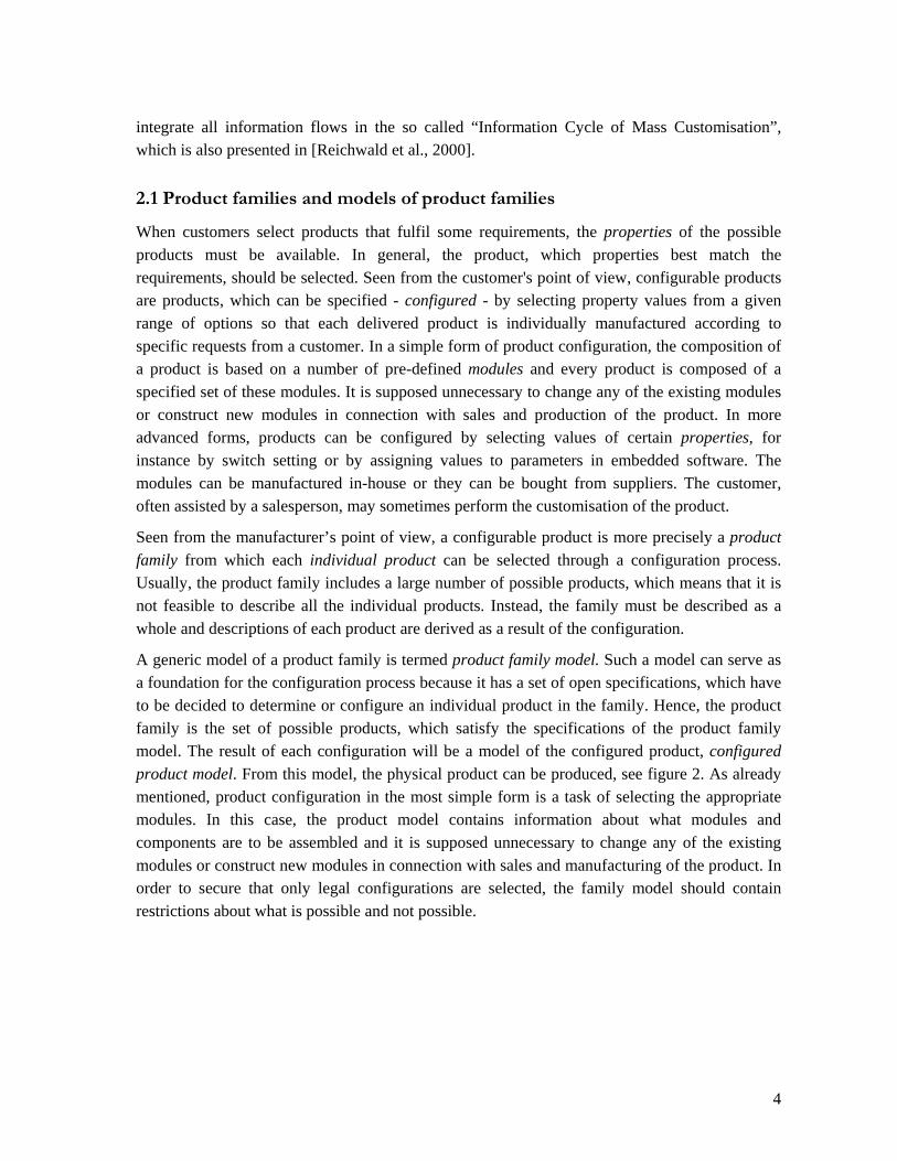
in order to achieve MC has been described comprehensively in the literature. [Berman, 2002] and [Pine, 1993] proposed that the use of modular product design combined with postponement of product differentiation would be an enabler to a successful MC implementation. This issue of course also relates to the question of readiness of the value chain.
An often used approach is to describe a series of products building a product family, which is described in one single model. Traditionally, a product family can be viewed as the set end products, which can be formed by combining a predefined set of modules [Faltings, 1998], [Jørgensen, 2003]. The product family model describes which modules are parts of the product family model and how they can be combined. When a product family model is implemented in a configurator, users are allowed to select modules to configure products, and even in some cases the user can select the desired properties of the end product and the configurator selects the corresponding modules [Jørgensen, 2003]. Several different methods for defining product models have been constructed during the latest years, each with their own advantages.
A “Procedure for building product models” is described in [Hvam, 1999] based on [Hvam, 1994]. It is a very practical approach with a seven step procedure, describing how to build a configuration system from process and product analysis to implementation and maintenance. For the product modelling purpose it uses the Product variant master method followed by object-oriented modelling to describe both classification and composition in a product family. The object-oriented approach is also applied by [Felfernig et al., 2001], who uses the Unified Modelling Language (UML) to describe a product family. This is done by using a UML meta model architecture, which can be automatically translated into an executable logical architecture. In contrast to [Hvam, 1999] this method focuses more on formulating the object-oriented product structure, rules and constraints most efficiently. The method also focuses on how the customers’ functional requirements can be translated into a selection of specific modules in the product family.
Mapping of functional requirements to specific modules is considered in [Jiao et al., 1998] and [Du et al., 2000], where it is proposed to use a triple-view representation scheme to describe a product family. The three views are the functional, the technical and structural view. The functional view is used to describe, typically the customers, functional requirements and the technical view is used to describe the design parameters in the physical domain. The structural view is used for performing the mapping between the functional and technical view as well as describing the rules of how a product may be configured.
Most of the methods, which exist for modelling configurable products, focus on modelling the solution space of a configuration process. This means that they describe the possible attributes of the products and the product structure as described above. Hence they do typically not focus on information, which is not directly used to perform the configuration itself. This information which could include e.g. customer, logistics and manufacturing information are according to [Reichwald et al., 2000] similarly important, since a successful implementation of MC must
4
integrate all information flows in the so called “Information Cycle of Mass Customisation”, which is also presented in [Reichwald et al., 2000].
2.1 Product families and models of product families
When customers select products that fulfil some requirements, the properties of the possible products must be available. In general, the product, which properties best match the requirements, should be selected. Seen from the customer's point of view, configurable products are products, which can be specified - configured - by selecting property values from a given range of options so that each delivered product is individually manufactured according to specific requests from a customer. In a simple form of product configuration, the composition of a product is based on a number of pre-defined modules and every product is composed of a specified set of these modules. It is supposed unnecessary to change any of the existing modules or construct new modules in connection with sales and production of the product. In more advanced forms, products can be configured by selecting values of certain properties, for instance by switch setting or by assigning values to parameters in embedded software. The modules can be manufactured in-house or they can be bought from suppliers. The customer, often assisted by a salesperson, may sometimes perform the customisation of the product.
Seen from the manufacturer’s point of view, a configurable product is more precisely a product family from which each individual product can be selected through a configuration process. Usually, the product family includes a large number of possible products, which means that it is not feasible to describe all the individual products. Instead, the family must be described as a whole and descriptions of each product are derived as a result of the configuration.
A generic model of a product family is termed product family model. Such a model can serve as a foundation for the configuration process because it has a set of open specifications, which have to be decided to determine or configure an individual product in the family. Hence, the product family is the set of possible products, which satisfy the specifications of the product family model. The result of each configuration will be a model of the configured product, configured product model. From this model, the physical product can be produced, see figure 2. As already mentioned, product configuration in the most simple form is a task of selecting the appropriate modules. In this case, the product model contains information about what modules and components are to be assembled and it is supposed unnecessary to change any of the existing modules or construct new modules in connection with sales and manufacturing of the product. In order to secure that only legal configurations are selected, the family model should contain restrictions about what is possible and not possible.

5
PF
CP1 CPkCP2 CPn
PP1 PP2 PPk PPn
ProductFamily
ConfiguredProduct
PhysicalProduct
Configuration
Manufacturing
Mod
el W
orld
Rea
l Wor
ld
Figure 2 - The product family model as the foundation for product configuration.
With this foundation, a product configurator can be defined as a tool - computer software - that can support the configuration process. When product configurators are based upon product family models, some information is extracted from this model and, in addition to that, it is necessary to develop a user interface by which the configuration can be performed.
2.2 Organisational Aspects
For production companies, which offer product configuration, usually most of the departments in the company are involved, not only sales, and production. Product configuration can be seen as the link between the sales and production, which tend to eliminate the traditional conflicts of interests. The sales department wishes to offer the customer precisely the products that the customers want, and often the salesperson is willing to go far in order to comply with any customer demands. On the other hand, the production department is interested in large number of standardised products so the production management is made less complicated.
The development department has to adapt the existing products and develop new products ready for configuration, i.e. they must have a modular architecture. Generally it can be said, that when a configurable product is to be developed, is must be designed after a generic product architecture, so the possibilities of different configurations are thought of already at the development stage. It is the experience of the authors that this is not always the case, causing problems with handling new configurations that, because of new demands from the customers, has become attractive. The production department must whitout higher cost produce and/or assemble the configurable products. This implies demand for flexible handling and fast changeover times. The sales department has to adjust to use a product configurator.
To have success in implementing product configuration it is essential, that the company not only define this as an IT-project. Only through a wide understanding of the company’s products, business processes, organisation and customers, product configuration can be adapted into the company and used in its full potential. The following section will describe how product configuration can affect the process from sale to delivery and the product development.
6
2.3 The Sales/delivery process
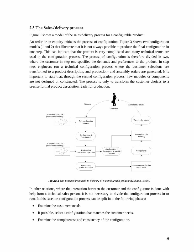
Figure 3 shows a model of the sales/delivery process for a configurable product.
An order or an enquiry initiates the process of configuration. Figure 3 shows two configuration models (1 and 2) that illustrate that it is not always possible to produce the final configuration in one step. This can indicate that the product is very complicated and many technical terms are used in the configuration process. The process of configuration is therefore divided in two, where the customer in step one specifies the demands and preferences to the product. In step two, engineers run a technical configuration process where the customer selections are transformed to a product description, and production- and assembly orders are generated. It is important to state that, through the second configuration process, new modules or components are not designed or constructed. The process is only to transform the customer choices to a precise formal product description ready for production.
Sale configurationprocess
Configuration 1:Specification
Engineeringconfiguration process
Componentproduction orders
Configuration 2:Description of specific
product
Configuration model(product metamodel) 1
Configuration model(product metamodel) 2
Component productionand/or stock
Components
Assemply and/orinstalling
The specific product
Demand Customized product
Customer
Figure 3 The process from sale to delivery of a configurable product [Sulonen, 1998].
In other relations, where the interaction between the customer and the configurator is done with help from a technical sales person, it is not necessary to divide the configuration process in to two. In this case the configuration process can be split in to the following phases:
• Examine the customers needs
• If possible, select a configuration that matches the customer needs.
• Examine the completeness and consistency of the configuration.

7
When there is a valid and complete configuration, cf. figure 3, a sales order can be generated.
2.4 Product development
For configurable products it is essential that models of the product families are developed. The purpose of the product family model is to describe the product family in a systematically and uniform way. In the product family model, all possible variants are defined due to the different modules that can be combined. When products are maintained or new products are developed, existing product family models can eventually be used as reference model.
It is necessary that a configurable product has a modular architecture. The modules that can substitute each other must have the same interface, so different functionalities can be made from combination of the modules.
Some companies offer partly configurable products, so that the customer can specify some of the functionalities, and the development department will be involved in satisfying more specific customer needs. If a specially designed product is produced for a customer and it is profitable to make it available for other customers, the necessary changes should be performed in the product family model. So, if the company later accept an order for this product, it will be an ordinary order on a configurable product. However, the product should not be visible in the product family model until fully detailed production documentation (bill of materials, routings etc.) for the product has been created.
2.5 What makes companies use product configuration?
According to [Sulonen, 1998], a Finnish research group who have been investigating what motives Finish companies have for using product configuration. The following are the most used motives (the order deflects the frequency that the companies mentioned it):
• Ability to fulfil a wide range of customer requirements
• Shorter lead times in the sales-delivery process
• Increased control of the production
• Reduction in customer-specific design
• Efficient way to offer a broad product line
• Improved quality
By working on projects with Danish companies, the experiences have shown that some of the motives for using product configuration are:

8
• Establish a link between the sales department and the production
• Secure fully specified orders
• Secure valid production documentation
• Easier to deal with large number of variants
• Less maintenance of production documentation
• A tool for proactive sale
It must be underlined that companies can have different motives to adapt to product configuration depending on the actual problem.
2.6 Product structure
The structural view of a product is that it consists of a number of components, which again can consist of other components, etc. The structure of a product and all its sub-components is a tree structure, see figure 4. Such a hierarchy gives an excellent overview of the selected components and the terms top-down and bottom-up are clearly defined according to the structure.
Product structure: Car Body Chassis Windows Doors Engine Interior Seats Control panel Displays Control buttons Wheels ....
Figure 4 - Sample product structure
In connection with product configuration, it is often advantageous to identify some modules on a level between components and the product. The idea is that modules are identified from a configuration point of view whereas components are identified from a manufacturing point of view. Usually, the number of modules is smaller than the number of related components.
Thus, in the structural model for configurable products, products consist of modules and modules consist of components. This decomposition into three levels is shown in figure 5.

9
P1 P2
M1 M2 M3 M4 M5
C1 C2 C4 C7 C8C3 C5 C6 C9
Product Level
Module Level
Component Level
Figure 5 Model of the structure with the three levels.
Generally, a product consists of modules and a module consists of components. However, a module may sometimes consist of other modules - sub modules. Furthermore, a component can be a part of the product directly (C8 in figure 5), for instance in the case, where the component is included automatically by the configurator. In the opposite case, individual components are identified as modules (C9 is defined as module M5 in figure 5).
2.7 Interfaces
Modules are often identified according to how it can interface with other modules, i.e. modules with the same interface can substitute each other (see figure 6). An example of this could be two modules where the only difference is the colour. The interfaces of modules contribute to the definition of the possible product structure.
Substitutablemodules
Partly substitutablemodules
Non substitutablemodules
Figure 6 Three different categories in which two modules can be classified.
2.8 Properties
Besides structure, products have properties. It is essential for both the customer and the producer to focus on properties of the resulting product. For each configured product, the resulting

10
properties are dependent of the selected components and structure of the product. In the product configuration process, algorithms must be available to estimate the resulting product properties. Some properties are simply the properties of the components, e.g. the colour of a car is normally defined as the colour of the car body. Other properties are computed from properties of the components. For example, the weight is simply the sum of the component's weight. However, not all resulting properties are so easy to determine. For instance, the resulting performance of a pump is a non-linear function of certain component properties. Much more complicated examples could be mentioned [Männistö, 2001].
3 Models and Modelling Modelling in various forms has always been a very important approach in design projects and new opportunities with computer-based modelling tools have made it even more important. Such tools have become more useful and with an increasing number of functionalities.
Often, the modelling tools dictate certain modelling methodologies with a number of limitations. However, modelling can be performed in many ways and can have different meanings to designers. The emphasis can be set on many subjects, decisions can be sequenced in many ways and resources can be allocated variously.
System Models and Systems Modelling
Methodologies for system development should be based on systems theory. With this respect, a system model is an intentionally simplified description of a system, fulfilling a certain purpose. Hence, a purpose must be specified and, accordingly, some choices are made in order to select the most important properties, components and relationships. Thus, a system model can e.g. be suitable for communication between designers, because with the model, it will be possible to concentrate on the most important aspects of the system.
System modelling includes two fundamental concepts analysis and synthesis.
Analysis (of an existing system) is 1) to investigate properties of the system and 2) to divide the system into system components and system structure.
Synthesis (of a new system) is 1) to create the system by relating existing systems to each other by a structure and 2) to add properties to the system.

11
Figure 7 - Analytic and synthetic modelling
Based on these concepts, models can be characterised as analytic models or synthetic models. Analytic models are models of something existing, often physical. Such models serve as a description, an abstraction, where a deliberate simplification is made, i.e. a selected set of properties, components and structures.
In contrast to analytic models, synthetic models are not built from anything existing but instead, a synthetic model is created as a foundation for some kind of new construction, which will become physical – an artefact. Hence, synthetic models are built purely from ideas, thoughts and imaginations and obtained in some kind of representation. The two modelling approaches are illustrated by figure 7. Consequently, design by modelling is a development approach, where a synthetic model is designed as an intermediate result and the final result is an implementation of the model in the real world.
It is important to realise that synthetic modelling does not purely include synthesis. It is normally a mixture of synthesis and analysis but synthesis is the primary substance. For instance, when a proposal is created, it is often appropriate to analyse a set of alternative possibilities. Design activities are basically regarded in this way.
Characteristically for synthetic modelling, it is also important to divide between two separate approaches: modelling of requirements and modelling of solutions. Modelling of requirements is to specify limitations for solutions as e.g. minimum/maximum values of selected attributes. Modelling of solutions is to generate possible alternative results that fulfil the requirements.
A fundamental reason for synthetic modelling is to enable manipulation and test of the model before the actual physical system is built. Modelling should make it possible to ensure that the design is correct and by various presentations of the model at different stages, it is possible to see the consequences of decisions and to reach a good impression of the final result.
Abs
trac
tion
Rea
lisat
ion
Analytic Model Synthetic Model
Object Artefact
Rea
l Wor
ldM
odel
Wor
ld
12
When synthetic modelling is performed, it is often important to view the model from many different aspects and to represent the model on many different abstraction levels. This is especially necessary at the beginning of the modelling process before any decisions are made about e.g. form and location.
Modelling with Abstraction and Detail
It is generally recognised that synthetic modelling includes working with various degree of abstraction. Two primary modelling dimensions are used: degree of abstraction regarding properties and degree of abstraction regarding structure. In synthetic modelling, the work develops along these dimensions from high degree of abstraction towards low degree of abstraction. High degree of abstraction regarding properties means that only a few properties are identified and, similarly, high degree of structure means that only a few overall components are identified.
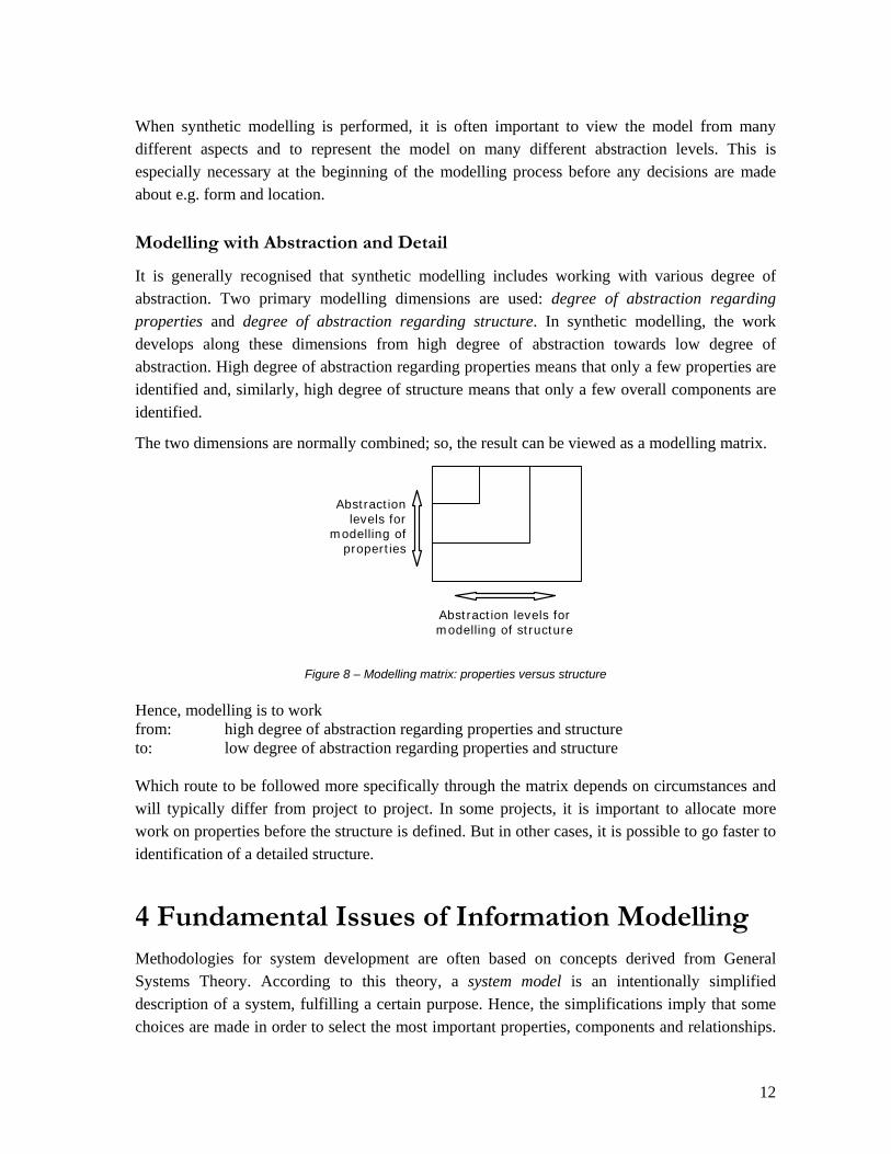
The two dimensions are normally combined; so, the result can be viewed as a modelling matrix.
Abstraction levels for
modelling of properties
Abstraction levels for modelling of structure
Figure 8 – Modelling matrix: properties versus structure
Hence, modelling is to work from: high degree of abstraction regarding properties and structure to: low degree of abstraction regarding properties and structure Which route to be followed more specifically through the matrix depends on circumstances and will typically differ from project to project. In some projects, it is important to allocate more work on properties before the structure is defined. But in other cases, it is possible to go faster to identification of a detailed structure.
4 Fundamental Issues of Information Modelling Methodologies for system development are often based on concepts derived from General Systems Theory. According to this theory, a system model is an intentionally simplified description of a system, fulfilling a certain purpose. Hence, the simplifications imply that some choices are made in order to select the most important properties, components and relationships.

13
Thus, a system model can e.g. be suitable for communication between designers, because with the model, it will be possible to concentrate on the most important aspects of the system. Models are viewed either as analysis models or synthesis models. Analysis models are models of something existing, often physical objects and synthesis models are models created as a foundation for construction of something new, which eventually will become physical – an artefact [Jørgensen, 2002]. Hence, synthesis models are built purely from ideas, thoughts and imaginations and obtained in some kind of representation. Design by modelling is a development approach, where a synthesis model is designed as an intermediate result and the final result is an implementation of the model in the real world.
Computer-based models are fundamentally stored in computers as data objects and data structures, which can be manipulated by applications. Therefore, development of tools for modelling includes both development of a data model and a number of applications with relationships to the data model [Jazayeri, 2000]. One of the most important requirements for the data model is that it is non-redundant so that no data value is stored more than once. In order to ensure that this requirement is fulfilled, the model representation has to be considered very carefully based on the meaning of data, the semantics. Therefore, the foundation for a data model is an information model ([Hammer 1978], [Rumbaugh et al. 1999] and [Halpin 2001]), created in combination with semantics from the domain, which the design model is addressing.
An important fundamental issue of information modelling is abstraction mechanisms, which provide the means for identification and design of invariant components and structures ([Smith 1977a], [Smith 1977b], [Rosch 1978] and [Sowa 1984]). Two abstraction mechanisms are defined here: composition and classification [Jørgensen, 1998]. Composition focuses on the components and the relationships between the components. The most frequently used structure is the component structure, which shows aggregation versus separation. Such a structure is illustrated in figure 9 for a sample computer.
Product structure: Computer Body Cpu CpuBoard Processor x 2 MemoryUnit x 3 GraphicBoard SoundBoard MassStorage HardDisc CdDrive PowerSupply Keyboard Mouse

14
Monitor PowerCable ....
Figure 9 – Sample composition structure of a computer
Classification focuses on identification of classes/types of components based on the properties/attributes, which characterise them. This can be illustrated in a diagram, termed taxonomy (see figure 10), where the relationships generalisation versus specialisation are shown. Often, a UML class diagram is used for the taxonomy ([Rumbaugh et al. 1999]).
In information modelling, composition and classification together support identification of fundamental structures on a type level as the basis for generation of individual components on an instance level and they provide the means to set particular focus on the most invariant decisions. A classification process results in a basic structure of types and a composition process results in a basic structure of components.
Another important issue of information modelling is the object-oriented paradigm, which can be adopted in harmony with the abstraction mechanisms. In this paradigm, each model component is regarded as a living organism, which act and interact with other components. Thus, object-oriented components are equipped with behavioural attributes, which enable them to respond to requests and, consequently, even if a real world component is non-living, the corresponding model is created as an active component.

15
Taxonomy: Computer components Mass storage components Hard discs Cd drives Dvd drives Print boards Cpu boards Graphic boards Io boards Sound boards Tv tuner boards Integrated circuits Processors Memory Units Cpu modules Mass storage modules Cables Power cables Disc cables Other Bodies Power supplies Keyboards Mice Monitors Computers ....
Figure 10 – Sample taxonomy of computer components
The two abstraction mechanisms are used in design tasks, but, as indicated in figure 11, classification is used first and composition afterwards. Classification primarily supports the identification of model components and the basic structure at the type level. Based on this, the structural considerations are identified by use of composition.
16
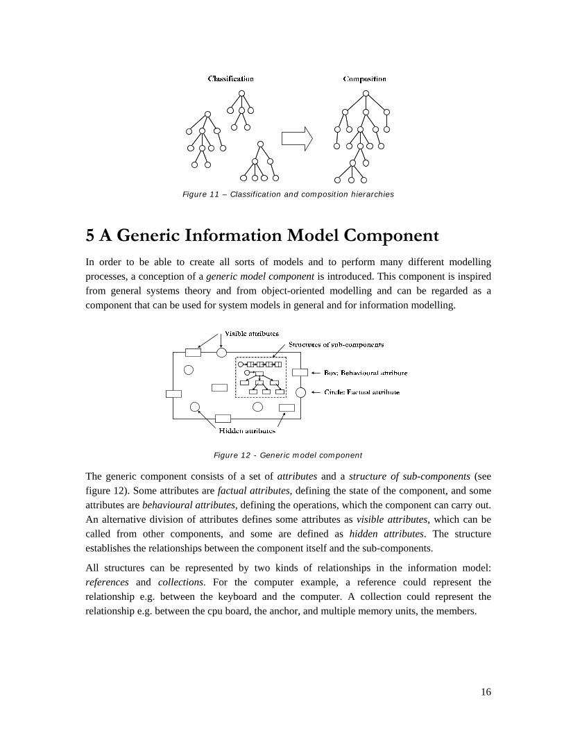
Figure 11 – Classification and composition hierarchies
5 A Generic Information Model Component In order to be able to create all sorts of models and to perform many different modelling processes, a conception of a generic model component is introduced. This component is inspired from general systems theory and from object-oriented modelling and can be regarded as a component that can be used for system models in general and for information modelling.
Figure 12 - Generic model component
The generic component consists of a set of attributes and a structure of sub-components (see figure 12). Some attributes are factual attributes, defining the state of the component, and some attributes are behavioural attributes, defining the operations, which the component can carry out. An alternative division of attributes defines some attributes as visible attributes, which can be called from other components, and some are defined as hidden attributes. The structure establishes the relationships between the component itself and the sub-components.
All structures can be represented by two kinds of relationships in the information model: references and collections. For the computer example, a reference could represent the relationship e.g. between the keyboard and the computer. A collection could represent the relationship e.g. between the cpu board, the anchor, and multiple memory units, the members.

17
Figure 13 - Object type is the basis for generating objects (instances)
When a synthesis information model is considered, a foundation for the components must be established by creating types of components. Component types are the primary content of information models and it is important to distinguish between modelling on the object level and modelling on the type level.
Each component type includes a specification of a set of attributes with name and data type. The classification abstraction mechanism is primary because, based on attributes, the component types can be classified and organised in a hierarchy, the taxonomy. Identification and specification of structures can also be included in the component types by creating the relations, which formulate the constraints regarding attributes and combinations of sub-components. The component type is a kind of template and, from each type, an indefinite number of components, instances, can be generated. The quality of these component types is the key basis to achieve an invariant information model foundation.
6 Product Family Modelling
There is a need for a methodology to describe and develop models of configurable products. Companies, who are implementing product configuration, need a comprehensive terminology and a systematic methodology in order to develop their modular products. It is of great importance to use well-defined terms and use the agreed terminology consistently in connection with a well-proven methodology, so that misunderstandings can be avoided and communication can be eased.
6.1 Attributes and Data Structures
As mentioned, products consist of properties, components and structure and similar contents goes for models of products and product families. In the following, the term attribute will be used in the models corresponding to properties of physical products. Consequently, when a configuration is performed, the desired properties of the resulting product must be determined by
18
defining values of attributes in the product family model. All relevant attributes of both the resulting product and the available modules must be specified and their optional values to be selected during configuration tasks must also be defined. In relation to this, it is important to notice that the selectable modules and components are sometimes substituted by one or more attributes. For instance, a door can be lockable (attribute) or it can be equipped with a lock (module/component). Therefore, the configuration process can be considered as a mixture of attribute specification and selection of modules, which together can satisfy the required attribute values.
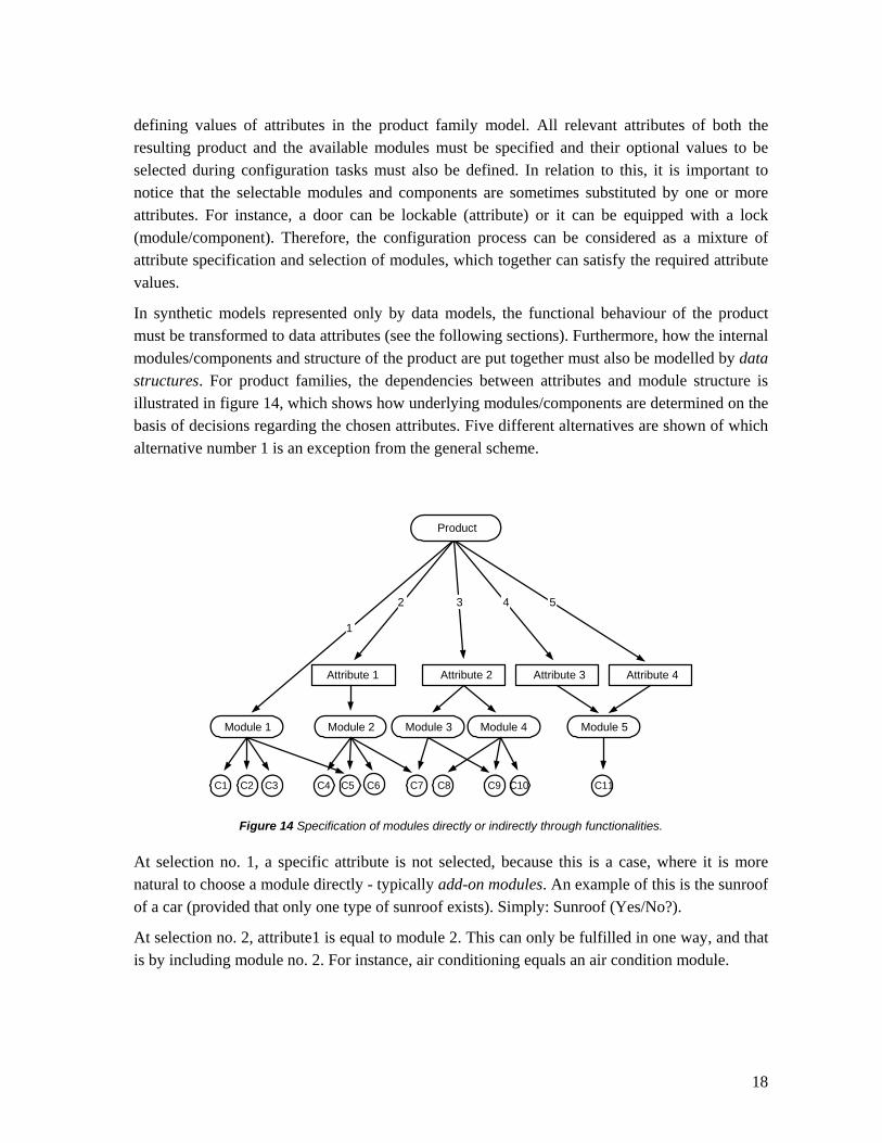
In synthetic models represented only by data models, the functional behaviour of the product must be transformed to data attributes (see the following sections). Furthermore, how the internal modules/components and structure of the product are put together must also be modelled by data structures. For product families, the dependencies between attributes and module structure is illustrated in figure 14, which shows how underlying modules/components are determined on the basis of decisions regarding the chosen attributes. Five different alternatives are shown of which alternative number 1 is an exception from the general scheme.
Attribute 1 Attribute 2
Module 2Module 1 Module 3 Module 4
Attribute 3 Attribute 4
Module 5
2 3 4 5
1
C1 C2 C3 C4 C5 C6 C7 C8 C9 C10 C11
Product
Figure 14 Specification of modules directly or indirectly through functionalities.
At selection no. 1, a specific attribute is not selected, because this is a case, where it is more natural to choose a module directly - typically add-on modules. An example of this is the sunroof of a car (provided that only one type of sunroof exists). Simply: Sunroof (Yes/No?).
At selection no. 2, attribute1 is equal to module 2. This can only be fulfilled in one way, and that is by including module no. 2. For instance, air conditioning equals an air condition module.

19
At selection no. 3, attribute no. 2 results in that both module no. 3 and 4 are selected. An example of this is that if the customer chooses the turbo car model, then both a turbo engine and ABS brakes must be selected.
Finally, selections no. 4 and 5 show a relatively usual case, where a module is determined by more than one attribute, i.e. attributes of the module. For instance, a seat can be specified from two attributes: the colour and whether there should be a headrest or not. When these two attributes are specified, then one module (a complete seat) can comply with both attributes.
6.2 Development of Product Family Models
As stated above, product family models must be able to construct individual product models through a configuration task. Each product model must have sufficient data about attributes and structure to describe and manufacture the physical product. Consequently, the basic elements of product family models are the total set of attributes of the possible product models and the set of identified modules, each with their internal attributes and data structures.
The basic units of a product family model are module types. A module type is a model of the set of modules, which are interchangeable, perhaps with some restrictions. During configuration, individual modules of each type are determined. The attributes of the product models and the module types are selected on the basis of what is important and relevant.
In the following, the contents of product family models are illustrated by use of simple elements of a synthetic language. Furthermore, fractions of a simple example of a computers product family model are added to the illustration.
Each attribute in a module type is defined by a name and probably a data type (Boolean, Integer, Float, String, Currency, etc.).
This declarative statement shows the syntax for description of a module type:
type name {…}
Example:
type HardDisk {...} The syntax of attribute declaration with data type is:
name : data type; Example:
type HardDisk { Name : string(50); StorageCapacity : integer; AccessTime : float; Price : currency;

20
} The available instances of a module type can be listed by a table with a column for each attribute and a row for each module.
Name StorageCapacity AccessTime PriceMaxtor 10K-3 37 Gb 4,5 ms 1.375 DKKMaxtor 10K-4 147 Gb 4,4 ms 4.055 DKKMaxtor 10K-5 300 Gb 4,4 ms 8.975 DKK
Alternatively, module data can be extracted from a database.
Some modules can be configured by selecting attribute values. In this case, each attribute is not defined by a data type but instead by a domain with the possible values. A domain can be a set of discrete values, an interval of integer values or a list of named values.
The syntax of an attribute declaration with domain and a possible default value is:
name : {domain} [default value];
Example:
type HardDisk { ..... PreSet : {Master, Slave} default Master; OperatingSystem : {Non, WinXP, Win2000, WinMe} default WinXP; ..... }
When module data are specified in form of a table as shown above, the selection of domain values can be added as columns to the table.
Attributes of a module can be a function of other attributes in the same module or in other modules. This can be modelled by an expression with standard functions or special functions as a special algorithm. If the name of a module type is included in such an expression, it means “number of instances of the type”.
Examples:
type Computer { OperatingSystem : Boolean default true; Colour = Case.Colour; HardDisks = HardDisk; DiskMemory = Sum(HardDisk.StorageCapacity); Weight = SumWeight : Double { ... Specific algorithm ... } ..... }
Structures are represented by special kind of attributes.

21
The symbol -> represents a reference i.e. a one-to-many relationship
Example:
type Processor { Name : string; ... ContainingBoard -> CpuBoard; }
The symbol ->> represents a collection i.e. a one-to-many relationship
Example:
type Cpu { ... RelatedGraphicBoards ->> GraphicBoard; RelatedIoBoards ->> IoBoard; ... }
Typically for module types, it is possible to add relations. In general, there are four different kinds of relations, see figure 15.
Figure 15 – Four kinds of relations
Among other things, relations of category 1 are used to specify product structures. Here, it is described that a product/module (instance of a module type) consists of modules (instances of other module types), which eventually also consist of modules etc. until the component level is reached. In a module type, such a relation expresses the module types for possible sub modules. Furthermore, a multiplicity is specified in order to form a basic expression about the number of instances that can be included.

22
The syntax for relations describing contents is:
contents { multiplicity module type; ... };
Multiplicities is formulated with the syntax:
from .. to where from is typically 0 or 1 and to is typically a fixed number or any number greater than or equal to from. This is indicated by a *.
Examples:
1..* from one to many 0..* from none to many 1..1 one and only one
Example:
type Cpu { ..... contents { 1..1 CpuBoard; 1..* Processor; 1..* MemoryUnit ;} ..... } type Case { ..... contents { 1..1 PowerSupply; 0..* PowerCable; } ..... }
All other kinds of relations are formulated by arithmetic expressions. Here, the ordinary arithmetic operators like addition, subtraction, multiplication and division can be used together with standard functions. The following arithmetic relation operators =, >=, <=, >, < and <> can also be used along with the logical operators AND, OR, XOR, NOT, implication (⇒) and bi-implication (⇔). If the name of a module type is included in a logical expression, it means ”instance of the type”.
Examples of relations with arithmetic and logical operators are:
type Cpu { constraints { GraphicBoard + IoBoard + TvTunerBoard <= NbOfBusSlots; Processor <= ProcessorSlots; .....

23
} } type Computer { constraints { Monitor <= 2; HardDisk + CdDrive + DvdDrive <= DiskCable * 2; OperatingSystem ⇒ HardDisk.OperatingSystem <> Non; CdDrive not ⇔ DvdDrive; ..... } }
It must be emphasised that classification and inheritance of attributes can also be included in the development of product family models, especially when many different types of modules are identified.
Classification of Module Types As previously stated, the classification abstraction mechanism is fundamental for identification and definition of types (see figure 10); hence, the module types above can be related to each other in a taxonomy.
The syntax of the relationships between super-types and sub-types is:
type name1 subtypeof name2 { ... }
Examples:
type ComputerComponent { ... } type MassStorageComponent subtypeof ComputerComponent { ... } type HardDisk subtypeof MassStorageComponent { ... } type Cpu subtypeof ComputerComponent { ... } type IntegratedCircuit subtypeof ComputerComponent { ... } type Processor subtypeof IntegratedCircuit { ... } type Other subtypeof ComputerComponent { ... } type Computer subtypeof Other { ... }
With classification, it is defined that attributes in super-types are inherited to sub-types.
24
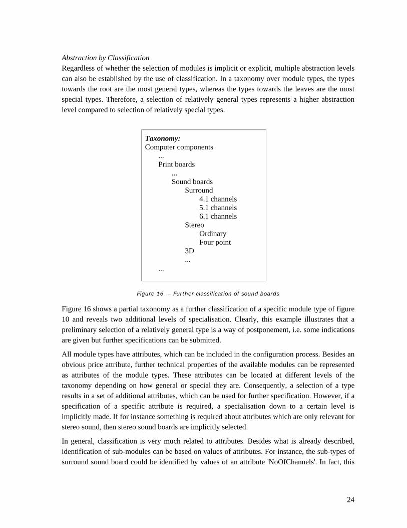
Abstraction by Classification Regardless of whether the selection of modules is implicit or explicit, multiple abstraction levels can also be established by the use of classification. In a taxonomy over module types, the types towards the root are the most general types, whereas the types towards the leaves are the most special types. Therefore, a selection of relatively general types represents a higher abstraction level compared to selection of relatively special types.
Taxonomy: Computer components ... Print boards ... Sound boards Surround 4.1 channels 5.1 channels 6.1 channels Stereo Ordinary Four point 3D ... ...
Figure 16 – Further classification of sound boards
Figure 16 shows a partial taxonomy as a further classification of a specific module type of figure 10 and reveals two additional levels of specialisation. Clearly, this example illustrates that a preliminary selection of a relatively general type is a way of postponement, i.e. some indications are given but further specifications can be submitted.
All module types have attributes, which can be included in the configuration process. Besides an obvious price attribute, further technical properties of the available modules can be represented as attributes of the module types. These attributes can be located at different levels of the taxonomy depending on how general or special they are. Consequently, a selection of a type results in a set of additional attributes, which can be used for further specification. However, if a specification of a specific attribute is required, a specialisation down to a certain level is implicitly made. If for instance something is required about attributes which are only relevant for stereo sound, then stereo sound boards are implicitly selected.
In general, classification is very much related to attributes. Besides what is already described, identification of sub-modules can be based on values of attributes. For instance, the sub-types of surround sound board could be identified by values of an attribute 'NoOfChannels'. In fact, this

25
attribute could remove the need for classification at the lowest level. Hence, if multiple classifications of these sound boards were relevant, i.e. if multiple and equally important classification criteria exit, it will be more flexible to identify the corresponding attributes and their possible values.
7 Product Configurator Development
7.1 Rule- versus constraint-based methods
The algorithms in a configuration application have the purpose of dealing with the restrictions and other relations there exist between the modules. These algorithms are traditionally modelled according to a rule-based method. This method use if-then constructions in the code. Another method is to use constraints. The primary advantages are that the constraint-based method is more elegant, needs less lines of code and has a better performance function. In figure 17, a further comparison is shown.
Rule-based method Constraint-based method
Building and maintaining is very difficult and time-consuming.
Building and maintaining is simpler.
The choice of modules/functionalities must be performed in a predefined order.
Freedom of making the choices in any sequence.
’Batch mode’, i.e. a number of choices are made as an input, after which the algorithm are executed with the possible consequence, that illegal choices has been made.
’Interactive model’, i.e. consequences are derived immediately after each choice.
Figure 17 Rule versus constraint-based algorithms in product family models [salesPLUS, 1997].
7.2 Inference method
Use of constraints in the product family model is an alternative compared to action rules, i.e. if-then statements. Hence, this approach is in contrast to the earlier mentioned implementations in GDL objects and in the ISO PLIB standard. The primary advantages are the following: the constraint representation is more elegant, constraints bases are smaller than rule bases and inference algorithms have a much better performance. In addition, the inference algorithm allow decisions about values of the product attributes to be made in any order, see [Sabin, 1998; Soininen, 2000] for a further comparison. Research results regarding knowledge-based systems have resulted in inference algorithms with very good performance [Møller, 1995].
Implemented in product configurators, such algorithms can be activated each time the user makes a selection [Yu, 1998; Array, 2003]. For large models, the process may take too much time in the beginning, but, after some selections, the results can be presented within reasonable

26
time. Referring to the constraints, this approach has the great advantage that the consequences for related attributes are shown before the next choice has to be made. This implies that, at each point of a configuration process, the already made decisions can be checked for consistency and, furthermore, it is possible to freeze these decisions and transform the configurator to a new configurator with the remaining decisions to be made by others. In this way, a good balance can be maintained between proprietary product family models and open product family models.
5.3 User interfaces
The design of product configurator user interfaces is very important and the great potential in using web technologies should not be underestimated. With this in mind, a large number of graphical components should be included where appropriate, i.e. drop-down lists, check boxes and radio buttons. In addition, automatic generation of visual effects in connection with the selectable options would be very helpful. For instance, when different colours are the option, this should be shown graphically and, when different modules can be selected directly or indirectly, they should be presented as graphic 3D images. Ultimately, the complete picture of the configured product should be generated and perhaps presented as a high quality rendered image in 3D stereo.
In order to include such graphical components in the user interface, it is important to include geometrical data in the product family model. This underlines the fact that a product model is more than a CAD model. When a product family model is the origin, it is obvious that geometrical data is only a part of the model. Attributes describing the product geometry may even be included as secondary attributes, where the values are derived through the internal constraints.
8 Summary The increasing demands from the customers to customisation have lead to the introduction of mass customisation and product configuration. Product configuration does not use the traditional product structure model, where each of the products consists of a number of components. Instead a module level is inserted between the components and the products, and combining the individual modules composes finished products.
The introduction and implementation of product configuration demand a systematically way of thinking in constructing, documenting, and maintaining the configurable products. This can be achieved by defining a product family model as a model of a set of possible products. A product family model includes description of module types with attributes, domains and constraints. The attributes, which can be decided in the configuration process, are termed functionalities. The constraints are used to describe the different relations, dependencies and connections between the module types and their attributes.
27
9 References [Array, 2003] Array Technology, www.array.dk, 2003.
[Bosch, 2000] J. Bosch: Design and use of software architectures - adopting and evolving a product-line approach. Addison-Wesley, 2000.
[Faltings, 1998] Boi Faltings and Eugene C. Freuder (Ed.): Configuration - Getting it right. Special issue of IEEE Intelligent Systems. Vol.13, No. 4, July/August 1998
[Jazayeri, 2000] M. Jazayeri, A. Ran and F. van den Linden: Software architecture for product families: Principles and practice. Addison-Wesley, 2000.
[Jørgensen, 1998] Kaj A. Jørgensen and Thomas Raunsbæk: Design of product configuration management systems. In: Proceedings of 2nd Int. Conf. on Engineering and Design, Hawaii. Integrated Technology Systems, Inc., 1998.
[Møller, 1995] Møller, G.: On the Technology of Array Based Logic. Ph.D. Thesis, Technical University of Denmark, 1995.
[Männistö, 2001] T. Männistö, T. Soininen and R. Sulonen: Product Configuration View to Software Product Families. In: Proceedings of Software Configuration Management Workshop (SCM-10). Toronto, 2001.
[Pine, 1993] B. Joseph Pine: Mass Customization - The New Frontier in Business Competition. Harvard Business School Press, Boston Massachusetts, 1993.
[Sabin, 1998] D. Sabin and R. Weigel: Product Configuration Frameworks - A survey. In IEEE intelligent systems & their appplications, 13(4):42-49, 1998.
[Soininen, 2000] T. Soininen: An approach to knowledge representation and reasoning for product configuration tasks. Doctoral thesis. Helsinki University of Technology. 2000.
[Sulonen, 1998] Reijo Sulonen, Juha Tiihonen, Timo Soininen, Tomi Männistö: Configurable Products - Lessons learned from the Finish Industry. In: Proceedings of 2nd International Conference on Engineering Design and Automation, Hawaii, Integrated Technology Systems, Inc., 1998.
[Yu, 1998] Yu, Bei and Skovgaard, Hans Jørgen: A Configuration Tool to Increase Product Competitiveness. In IEEE Intelligent Systems, vol. 13, no. 4, 1998.