Product Catalog - Remote Control Technology: Wireless Remote Control...
30
Product Catalog Simple Wireless Solutions www.remotecontroltech.com Innovative Applications for Wireless Control and Telemetry
Transcript of Product Catalog - Remote Control Technology: Wireless Remote Control...

Product CatalogSimple Wireless Solutions
www.remotecontroltech.com
Innovative Applicationsfor
Wireless Control and Telemetry

About Remote Control Technology
Welcome....................................................................2
Why Go Wireless?.....................................................3
Simple Wireless Applications....................................4
Custom Wireless Applications...................................5
Stationary Wireless Solutions
Wireless Automation System.....................................6
Long Range Wireless Switch System......................12
Medium Range Wireless Switch System.................14
Short Range Wireless Switch Systems...................16
Handheld Wireless Solutions
Long Range Wireless Switch System Handheld.....18
Wireless Multi-Switch Controller..............................20
Short Range Wireless Switch System Handheld.....22
Accesories
Solar Power Systems..............................................26
Antennas.................................................................28
Table of Contents
2014 Volume 1

www.remotecontroltech.com (866) 701-1146
Welcome to Remote Control Technology!Thank you for your interest in Remote Control Technology’s (RCT) products. In this catalog, you will fi nd valuable information about our products, a brief education of the radio frequency (RF) spectrum and easy-to-follow diagrams showing how RCT provides solutions that are cost-effective and simple to use.
Founded in 1982 under the name TRC Systems, the original product line, known as “RIC”, was developed to fi ll the need for a more effi cient method of servicing automatic sprinkler systems. The company changed its name to Remote Control Technology in 1988 and sold its irrigation division, now known as TRC Irrigation Remotes, in 2005. Today, Remote Control Technology provides simple wireless solutions for control, automation and telemetry in a wide variety of industrial applications, including automated pump controls, wireless tactical airfi eld lighting and remote temperature monitoring. Anything that can be switched (e.g. On/Off, Up/Down) or that can send and receive data can be done so wirelessly. Remote Control Technology is a global leader in the wireless solutions industry, providing unique, application-focused engineering and systems integration capabilities. We are able to meet diverse customer requirements by continually expanding our product and service offerings. Remote Control Technology has designed, manufactured and supplied both custom and off-the-shelf product solutions and services for a variety of domestic and international customers including Boeing, Raytheon, the U.S. Military, Transfi eld Services, Maxum Petroleum, U.S. National Parks, Columbia Research, L-3 Communications, Washington State Ferries and Benetech Brazil. Contact RCT today to see how our Simple Wireless Solutions can help you and your company save time and money.
For More Information Contact:Remote Control TechnologyIndustrial Sales Manager14736 NE 95th StRedmond, WA 98052Phone: (866) 701-1146FAX: (425) [email protected]
©1982-2014 Remote Control Technology. All rights reserved. The names of companies and products mentioned herein may be the trademarks of their respective owners. Unless stated to the contrary, no association with any other company or product is intended or should be inferred.
2

Simple Wireless Solutions
www.remotecontroltech.com (866) 701-1146
Why Go Wireless?
Remote Control Technology’s line of dependable, durable wireless switching systems can and will make money for you and your business.
• Legal issues – Obtaining access to or traversing properties with hard lines is extremely diffi cult.
• No copper wire to steal – As the price of copper increases, so does the possibility that your wire will be stolen. Using a wireless system means no wire for thieves to steal.
• Extended range – Unlike much of the equipment on the market, RCT’s wireless equipment has long-range communication capabilities.
• Eliminate need for wire and conduit – Wire and conduit are expensive and high- maintnance. Typical wear-and-tear, digging, rodent damage, theft, etc., are all examples of problems that can damage wire. RCT’s wireless systems put an end to these drawbacks of wired technology.
• Profi tability – Wireless switching systems eliminate the costly, labor-intensive process of trenching and laying wire. As a result, the contractor can enjoy an increased profi tability of 200 percent or more in this facet of the job.
• No FCC licensing issues – RCT equipment does not require FCC licensing, whereas much of the other equipment on the market does. This is a signifi cant benefi t, as the FCC licensing process alone may take up to 8 weeks.
• Less maintenance and servicing – In many states a contractor is obligated by law to maintain pumping systems for up to a year after its installation. RCT switching systems eliminate a majority of these maintenance and servicing issues by automating the job. Fewer service calls mean better profi tability while working.
• Reliability and compatibility – All of the components that a contractor puts into a project must agree with one another and have the utmost reliability. RCT equipment has proven to be highly compatible with standard equipment used in most industries, as well as offering unparalleled reliability in use with programmable logic controllers (PLCs), various switches and relays, etc.
3
Simple Wireless Solutions
Applications
Applications Include:
Pumps, Valves, Relays, Conveyors, Tank Level, Alarm Systems, PLC Activation, Data Monitoring, Automation
Phone: (866) 701-1146Fax: (425) 216-7558
www.remotecontroltech.com
Simple Wireless ApplicationsThe applications for simple wireless switching are limitless. Nearly any device that can be turned on or off electrically can be controlled remotely using Remote Control Technology’s wireless switching technology. From tactical airfi eld lighting to automating pump operations, Remote Control Technology’s goal is to provide a Simple Wireless Solutionthat is easy to install and operate. The following applications are examples of Wireless Switch System usage:
4 www.remotecontroltech.com (866) 701-1146
Wireless Tank Level Automation:Our Wireless Switch Systems are commonly used to control water tank levels in many major cities, municipalities and water districts. A transmitter connected to a fl oat switch of a water tank allows a receiver that is connected to a pump to maintain the water level of the tank. When the water lowers to a specifi ed level, the transmitter will send an “ON” transmission to the receiver, turning on the pump. Once the specifi ed level has been reached, the transmitter sends an “OFF” transmission to the receiver, shutting the pump off.
Alarm Notifi cation:Retrofi tting different alarm systems, such as severe weather warnings, fi re alarms, security alarms, etc., can be costly and time-consuming. Using simple wireless switching from Remote Control Technology eliminates the need for expensive copper wiring and trenching and can be installed quickly.
Wireless Conveyor Control:When installed on a conveyer, a Wireless Switch System allows the operator to quickly assess the fl ow of product along a conveyor without being confi ned to the location of the control panel. A Wireless Switch System receiver connected to a PLC can be confi gured to control start, stop, backward, forward, fast and slow conveyor functions. The Wireless Switch System transmitter can be affi xed to a vehicle or held by the operator, allowing the operator to load or dump material without having to leave the vehicle.
Wireless Industrial Automation:Advances in sensor technology have mirrored the advances in the silicon industry. As processors become smaller, sensors have become smarter, with increased sensitivity and functionality. An analog device, such as a temperature or fl ow sensor, connected with a 4-20 mA output as well as to one of today’s smart relays can be used in conjunction with a Wireless Switch System. One now has the ability to use the output of the sensor to control a device such as a PLC, conveyor or alarm, as well as lighting, valves, gates and any other device that needs to be remotely switched based on the output of a sensor.
Wireless Lighting Solutions:Remote Control Technology’s Wireless Switch Systems are an ideal solution for wireless lighting needs. Lights can be turned on or off from within a radius of up to 5 miles* from any fi xed position, such as a control tower, a mobile handheld position, or even an aircraft. The Wireless Switch System allows the user to remotely turn on and off lights without physically fl ipping a switch, leaving a vehicle, or being exposed to the elements.
*The range of all radio products is dependent of local conditions and antenna selection/location.

Applications Include:
Pumps, Valves, Relays, Conveyors, Tank Level, Alarm Systems, PLC Activation, Data Monitoring, Automation
Phone: (866) 701-1146Fax: (425) 216-7558
www.remotecontroltech.com
Custom Wireless ApplicationsThe applications for simple wireless switching are limitless. If an off-the-shelf system is not ideal for an application, a custom solution must be created. Using Remote Control Technology’s simple wireless solutions, we can design, develop and support wireless systems that can solve almost any industrial problem. The following are examples of custom applications using the Wireless Switch System:
www.remotecontroltech.com (866) 701-1146 5
The Need: This application involved a ½ mile conveyor that transported aggregate to a main processing facility. Operators of bulldozers needed to select the source and destination of different gravel types. Using walkie-talkies was ineffective and led to many errors. Hardwiring would have required the operators to exit their equipment and would have been ineffi cient. The Solution: Remote Control Technology designed a custom 24-output receiver to be used in conjunction with a PLC as part of a control system upgrade. This allowed the plant manager and D-9 Cat operators to select and operate many different conveyors. This application worked so well that popularity demanded RCT to create a standard product titled the Wireless Multi-Switch Controller, displayed on pages 14 and 15.
The Need: For an application with the U.S. Army, Laser Guidance needed wireless remote controls used for temporary, tactical airfi eld lighting. This would allow U.S. Army personnel to activate battery-powered runway lights (LED and infrared) from a helicopter.
The Solution: Remote Control Technology and Laser Guidance supplied the U.S. Army with a wireless remote system for tactical airfi eld lighting. The Remote Control Technology system enabled wireless switching of battery-powered airfi eld runway lights (LED and infrared) for covert military operations. Remote Control Technology’s custom RF receivers were positioned along the edges of a temporary aircraft landing pad or runway. These lights are activated by a handheld FM transmitter or by an approaching helicopter.
*The range of all radio products is dependent of local conditions and antenna selection/location.
Laser Guidance® Redmond, Washington
Stoneway Cement® Seattle, Washington
Puget Sound Energy® Bellevue, Washington
The Need: To aid in the protection of the Northwest salmon on the Baker Dam, Puget Sound Energy needed a wireless remote control to operate an underwater fi sh screen and allow the passage of boats without damaging the screens. The wireless remote had to integrate with the PLC used to raise and lower the screen.
The Solution: Remote Control Technology modifi ed a Handheld Wireless Switch System to integrate with the screen PLC. This allowed maintenance and boat operators to raise and lower the fi sh screen using a handheld transmitter on the boat and from the dam control center.
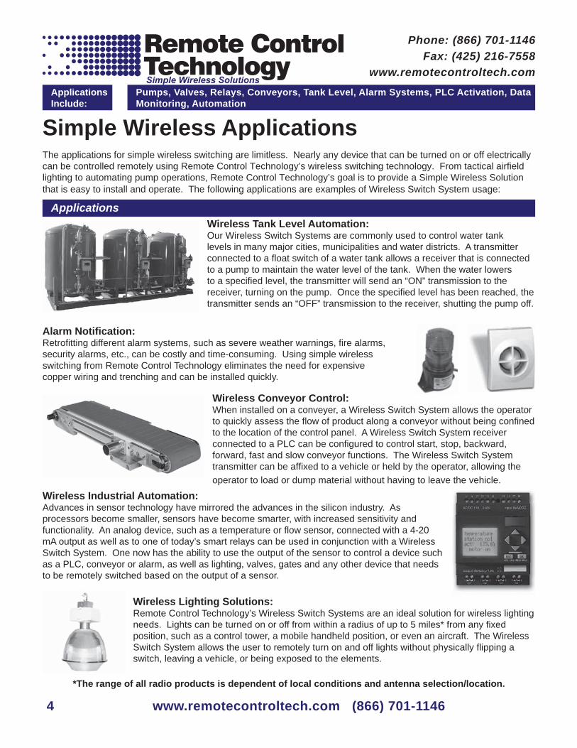
Wireless Automation System Part #:80442SThe Wireless Automation System is a 900 MHz radio frequency network with integrated I/O that can operate in most environ-ments while eliminating the need for wiring runs. Systems are built around a Gateway, which acts as the wireless network master device, and one or more Nodes.
Pump Control• Flow Rate Monitoring• Conveyor Control•
Tank Level Monitoring• Light Control• Alarm Systems•
PLC Activation• Data Logging• Wireless Automation•
The Wireless Automation System combines Frequency Hopping Spread Spectrum (FHSS) technology and Time Division Multiple Access (TDMA) control architecture to ensure reliable data delivery within the unlicensed Industrial, Scientifi c, and Medical (ISM) bands. The transceivers provide two-way communication between the Gateway and Node, including fully acknowledged data transmission site survey analyses. Lost RF links are detected, and relevant outputs set to user-defi ned conditions. Each device comes with four discrete inputs, four discrete (sourcing) outputs, two analog (0–20 mA) inputs, and two analog (0–20 mA) outputs.
Operation
Wireless Automation System Gateway Specifi cations
Applications Include:
Pumps, Valves, Relays, Conveyors, Tank Level, Alarm Systems, PLC Activation, Data Monitoring, Automation
Phone: (866) 701-1146Fax: (425) 216-7558
www.remotecontroltech.com
www.remotecontroltech.com (866) 701-1146
The Wireless Automation System provides reliable monitoring, without the burden of wiring or conduit installation, and can operate independently of or in connection with a PLC and/or PLC Software. Each wireless system consists of one gateway and one or more nodes. The gateway device works as the master within each radio network system. The gateway initiates communication and reporting with the node. Each node can be connected to a sensor or output device and report back the state of the I/O to the master. The gateway and nodes can be arranged to extend the range (3 miles) of the network or to avoid obstacles in the transmissions path. The transceivers provide two-way communication between the gateway and node including fully acknowledged data transmissions.
WAS Gateway Part #: 80442G
The range of all radio products is dependent on local conditions and antenna selection/location.
WAS NodePart #: 80442N
The WAS analog output will connect to any controller that reads 4-20 mA data such as a fl ow meter, data logger, tank level
indicator, or process meter.
6
Power Requirements
Supply Power: 24 VDC(15 W power supply included)100VAC-240VAC Input
Radio Frequency: 900 MHz distance up to 2 miles(Frequency Hopping Spread Spectrum)FCC Part 15 compliant (License Free)
Operating Environment
Indoor or Outdoor32° F to 122° F
Discrete Inputs 4 Dry Contact Inputs (Switch)
Analog Input Ratings
Analog Input Rating. 24 mAAnalog Input Sample Rate. 62.5 millisecondsAnalog Report Rate. 1 second or on Change of State (1% change in value)Accuracy. 0.1% of full scale +0.01% per °C
Output Ratings Analog Update Rate 125 millisecondsAccuracy 0.1% of full scale +0.01% per °C
Relay Outputs 4 Class C Relays Rated 6A @ 250V
* The range of all radio products is dependent on local conditions and antenna selection/location.

Wireless Automation and Telemetry Made Easy!
www.remotecontroltech.com (866) 701-1146 7
• Wireless industrial I/O device with four discrete inputs, four discrete (sourcing) outputs, two analog (0–20 mA) inputs, and two analog (0–20 mA) outputs.• The ability to add multiple nodes to the system• Transceivers provide two-way communication between the Gateway and Node, including fully acknowledged data transmission.• Point to multi-point communication • Site Survey analyzes the network’s signal strength and reliability.• Lost RF links are detected and relevant outputs set to user-defi ned conditions.
Pump
Relay
Node
Liquid Sensor
Gateway Node
Data Logger
Analytical SoftwareTransmits an on/off signal to the node,
which turns the pump (or other device) on
or off
Transmits a 0-20mA analog data signal to a
data reading device indicating sensor
reading
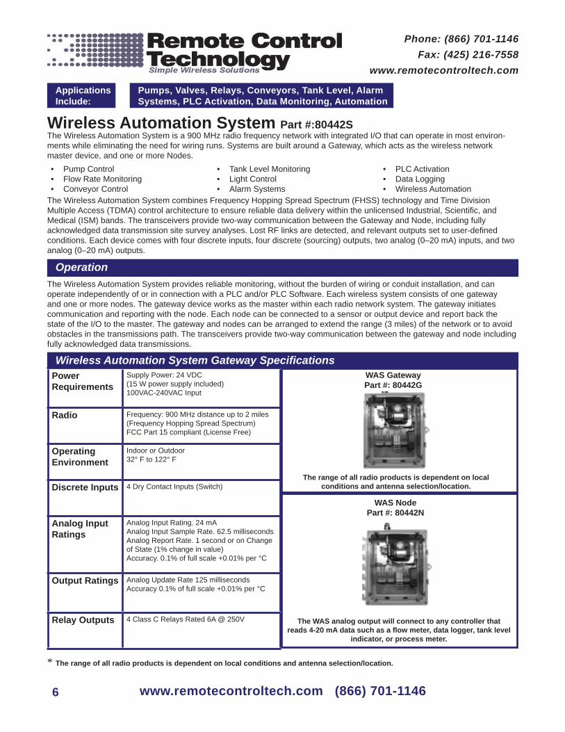
Wireless Automation System Part #:80222SThe Wireless Automation System is a 900 MHz radio frequency network with integrated I/O that can operate in most environ-ments while eliminating the need for wiring runs. Systems are built around a Gateway, which acts as the wireless network master device, and one or more Nodes.
Pump Control• Flow Rate Monitoring• Conveyor Control•
Tank Level Monitoring• Light Control• Alarm Systems•
PLC Activation• Data Logging• Wireless Automation•
The Wireless Automation System combines Frequency Hopping Spread Spectrum (FHSS) technology and Time Division Multiple Access (TDMA) control architecture to ensure reliable data delivery within the unlicensed Industrial, Scientifi c, and Medical (ISM) bands. The transceivers provide two-way communication between the Gateway and Node, including fully acknowledged data transmission site survey analyses. Lost RF links are detected, and relevant outputs set to user-defi ned conditions. Each device comes with two discrete inputs, two discrete (sourcing) outputs, two analog (0–20 mA) inputs, and two analog (0–20 mA) outputs.
Operation
Wireless Automation System Gateway Specifi cations
Applications Include:
Pumps, Valves, Relays, Conveyors, Tank Level, Alarm Systems, PLC Activation, Data Monitoring, Automation
Phone: (866) 701-1146Fax: (425) 216-7558
www.remotecontroltech.com
www.remotecontroltech.com (866) 701-1146
The Wireless Automation System provides reliable monitoring, without the burden of wiring or conduit installation, and can operate independently of or in connection with a PLC and/or PLC Software. Each wireless system consists of one gateway and one or more nodes. The gateway device works as the master within each radio network system. The gateway initiates communication and reporting with the node. Each node can be connected to a sensor or output device and report back the state of the I/O to the master. The gateway and nodes can be arranged to extend the range (3 miles) of the network or to avoid obstacles in the transmissions path. The transceivers provide two-way communication between the gateway and node including fully acknowledged data transmissions.
WAS Gateway Part #: 80222G
The range of all radio products is dependent on local conditions and antenna selection/location.
WAS NodePart #: 80222N
The WAS analog output will connect to any controller that reads 4-20 mA data such as a fl ow meter, data logger, tank level
indicator, or process meter.
8
Power Requirements
Supply Power: 24 VDC(15 W power supply included)100VAC-240VAC Input
Radio Frequency: 900 MHz distance up to 2 miles(Frequency Hopping Spread Spectrum)FCC Part 15 compliant (License Free)
Operating Environment
Indoor or Outdoor32° F to 122° F
Discrete Inputs 2 Dry Contact Inputs (Switch)
Analog Input Ratings
Analog Input Rating. 24 mAAnalog Input Sample Rate. 62.5 millisecondsAnalog Report Rate. 1 second or on Change of State (1% change in value)Accuracy. 0.1% of full scale +0.01% per °C
Output Ratings Analog Update Rate 125 millisecondsAccuracy 0.1% of full scale +0.01% per °C
Relay Outputs 2 Class C Relays Rated 6A @ 250V
* The range of all radio products is dependent on local conditions and antenna selection/location.
Wireless Automation and Telemetry Made Easy!
www.remotecontroltech.com (866) 701-1146 9
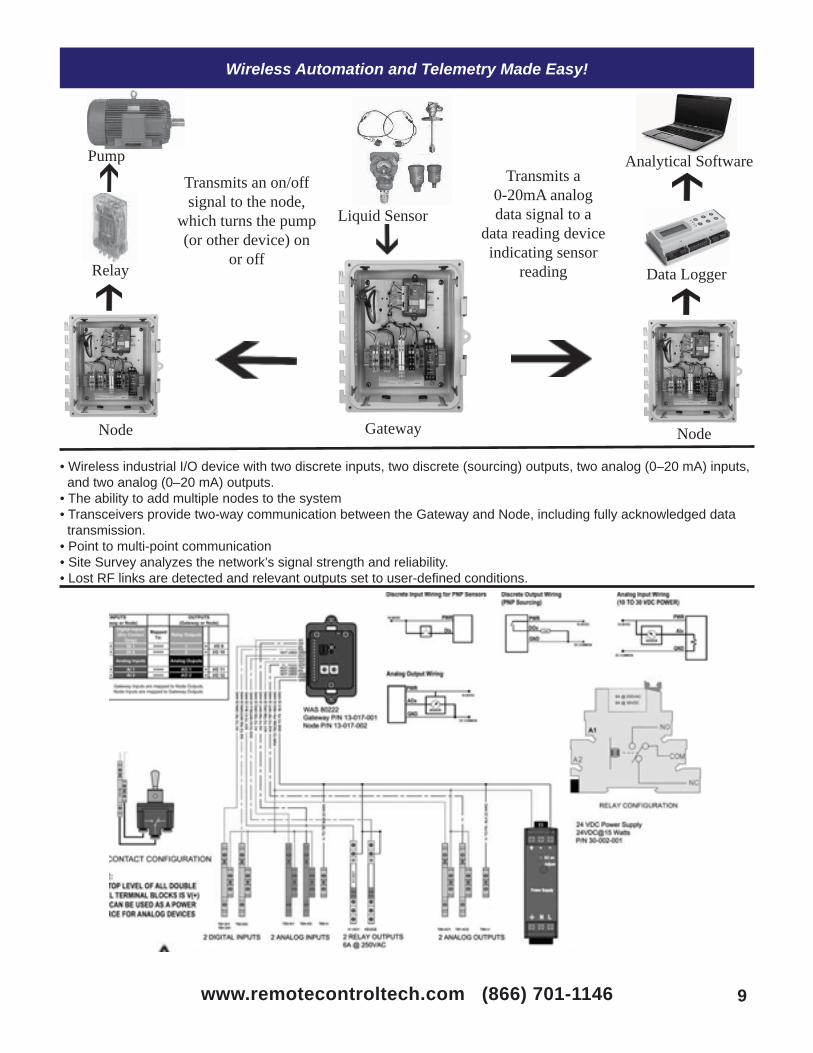
• Wireless industrial I/O device with two discrete inputs, two discrete (sourcing) outputs, two analog (0–20 mA) inputs, and two analog (0–20 mA) outputs.• The ability to add multiple nodes to the system• Transceivers provide two-way communication between the Gateway and Node, including fully acknowledged data transmission.• Point to multi-point communication • Site Survey analyzes the network’s signal strength and reliability.• Lost RF links are detected and relevant outputs set to user-defi ned conditions.
Pump
Relay
Node
Liquid Sensor
Gateway Node
Data Logger
Analytical SoftwareTransmits an on/off signal to the node,
which turns the pump (or other device) on
or off
Transmits a 0-20mA analog data signal to a
data reading device indicating sensor
reading
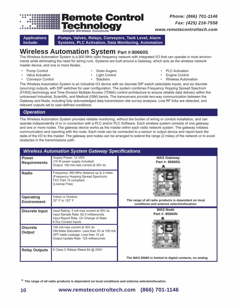
Wireless Automation System Part #:80660SThe Wireless Automation System is a 900 MHz radio frequency network with integrated I/O that can operate in most environ-ments while eliminating the need for wiring runs. Systems are built around a Gateway, which acts as the wireless network master device, and one or more Nodes.
Pump Control• Valve Actuation• Conveyor Control•
Grain Augers• Light Control• Stackers•
PLC Activation• Engine Control• Wireless Automation•
The Wireless Automation System is an industrial I/O device with six discrete DIP switch selectable inputs, and six discrete (sourcing) outputs, with DIP switches for user confi guration. The system combines Frequency Hopping Spread Spectrum (FHSS) technology and Time Division Multiple Access (TDMA) control architecture to ensure reliable data delivery within the unlicensed Industrial, Scientifi c, and Medical (ISM) bands. The transceivers provide two-way communication between the Gateway and Node, including fully acknowledged data transmission site survey analyses. Lost RF links are detected, and relevant outputs set to user-defi ned conditions.
Operation
Wireless Automation System Gateway Specifi cations
Applications Include:
Pumps, Valves, Relays, Conveyors, Tank Level, Alarm Systems, PLC Activation, Data Monitoring, Automation
Phone: (866) 701-1146Fax: (425) 216-7558
www.remotecontroltech.com
www.remotecontroltech.com (866) 701-1146
The Wireless Automation System provides reliable monitoring, without the burden of wiring or conduit installation, and can operate independently of or in connection with a PLC and/or PLC Software. Each wireless system consists of one gateway and one or more nodes. The gateway device works as the master within each radio network system. The gateway initiates communication and reporting with the node. Each node can be connected to a sensor or output device and report back the state of the I/O to the master. The gateway and nodes can be arranged to extend the range (2 miles) of the network or to avoid obstacles in the transmissions path.
Power Requirements
Supply Power: 12 VDC(15 W power supply included)Output: 100 mA max current at 30V dc
Radio Frequency: 900 MHz distance up to 2 miles(Frequency Hopping Spread Spectrum)FCC Part 15 compliant (License Free)
Operating Environment
Indoor or Outdoor32° F to 122° F
WAS Gateway Part #: 80660G
The range of all radio products is dependent on local conditions and antenna selection/location.
The WAS 80660 is limited to digital contacts, no analog.
Discrete Input Input Rating. 3 mA max current at 30V dcInput Sample Rate. 62.5 millisecondsInput Report Rate. On Change of State6 Dry Contact Inputs
Discrete Output
100 mA max current at 30V dcON-State Saturation: Less than 3V at 100 mAOFF-state Leakage: Less than 10 μAOutput Update Rate. 125 milliseconds
Relay Outputs 6 Class C Relays Rated 6A @ 250V
WAS NodePart #: 80660N
10
* The range of all radio products is dependent on local conditions and antenna selection/location.

Wireless Automation and Telemetry Made Easy!
www.remotecontroltech.com (866) 701-1146 11
• Wireless industrial I/O device with six discrete inputs and six discrete (sourcing) outputs.• The ability to add multiple nodes to the system.• Point to Multy-point communication • Transceivers provide two-way communication between the Gateway and Node, including fully acknowledged data transmission.• Lost RF links are detected and relevant outputs set to user-defi ned conditions.
Switch Gateway Node
Relay Relay Relay Relay Relay Relay
Traffi c LightMotorConveyorPumpBeaconPortable Lights

Long Range Wireless Switch System Part #: 01210
The Long Range Wireless Switch System (LRWSS) is designed for long range (up to 5 miles*) and simple wireless switching. The LRWSS is the simple solution for applications where faulty wire replacement or new installation is not possible or practical. Possible applications include:
Pump Control• Valve Actuation• Conveyor Control•
Grain Augers• Light Control• Stackers•
PLC Activation• Engine Control• Wireless Automation•
The LRWSS consists of a six-input transmitter and a six-output (12 VDC) receiver. It comes complete with power supplies and antennas; all you need to do is connect the devices you want to control, and the LRWSS is ready for use and guaranteed to perform.
Operation
6 Dry Contact Input Transmitter Specifi cations
6 12VDC Output Receiver Specifi cations
Applications Include:
Pumps, Valves, Relays, Conveyors, Grain Augers, Alarm Systems, PLC Activation, Stackers, Automation
Phone: (866) 701-1146Fax: (425) 216-7558
www.remotecontroltech.com
www.remotecontroltech.com (866) 701-1146
Operation is simple: connect a switch, relay, or any device with a dry contact closure to the transmitter inputs (terminal block). When a contact is closed, the transmitter will immediately send an “ON” transmission to the receiver, changing the state of the selected receiver output from 0 VDC to 12 VDC @ 1 amp. The receiver output can be used to activate a relay, solenoid, or light. Immediately after a contact is open, the transmitter will send an “OFF” transmission to the receiver, changing the state of the selected output from 12 VDC to 0 VDC and turning off the connected device. Solar Panel Kits: Turnkey, 12 VDC solar panel kits are available for locations without electricity.
Power Requirements
Supply Power: 12 VDCpower supply IncludedXMIT Current: 200 mASTBY Current: 35 mA
Radio Output: 4 watts (5 mile* potential range)Frequency: 26.995 FMFormat: PDTFM FSKFCC Part 95 Subpart E compliance(no license required)
Operating Environment
Indoor or Outdoor32 degrees F to 122 degress F
Includes:6 input, 4 watt radio transmitter• 15 watt power supply (110 VAC to 240 •
VAC input, 12 VDC output)42” high-gain antenna• Right-Angle Antenna Mount• 25’ coaxial cable w/ BNC connectors•
Power Requirements
Supply Power: 12 VDC(15 W power supply included)Output Current: 1 amp per outputSTBY Current: 45 mA
Radio Frequency: 26.995 MHz FMsuperheterodyne FM receiverFCC Part 15 Compliance(no license required)
Operating Environment
Indoor or Outdoor32 degrees F to 122 degress F
LRWSS ReceiverPart #: 01216
Includes:6 output receiver• 15 watt power supply (110 VAC to 240 VAC •
input, 12 VDC output)NEMA 4X enclosure• 42” high-gain antenna• Right-Angle Antenna Mount• 25’ coaxial cable w/ BNC connectors•
LRWSS TransmitterPart #: 01217
Mounted in metal NEMA 4X enclosures, the LRWSS is designed for outdoor/indoor industrial applications. Remote Control Technology also offers a three-year warranty for this system. The transmitter has an output power of 4 watts @ 26.995 MHz. The potential range is approximately 5 miles* and, with proper antenna application, is not limited to line-of-sight communication.
*The range of all radio products is dependent on local conditions and antenna selection/location.
12

The Simple Solution for All Your Wireless Switching Needs!
The range of devices that can be controlled with this system are limitless; the picture above • only shows a few of the possible applications for the LRWSS.
Control up to six devices from up to 5 miles away without line-of-sight*.• Performance is backed by a three-year warranty.• The wiring diagram below gives an example of how to connect the system using a push- •
button switch to wirelessly control a motor:
www.remotecontroltech.com (866) 701-1146 13

Medium-Range Wireless Switch System Part #: 01240
The Medium Range Wireless Switch System (MRWSS) is designed for medium range (up to 2 miles*) and simple wireless switching. The MRWSS is the simple solution for applications where faulty wire replacement or new installation is not possible or practical. Examples include:
Pump Control• Valve Actuation• Conveyor Control•
Grain Augers• Light Control• Stackers•
PLC Activation• Engine Control• Wireless Automation•
The MRWSS consists of a transmitter with two dry-contact inputs, and a receiver with two relay outputs. Each unit comes in a NEMA 4X enclosure with power supplies and antennas. Simply make your connections and the MRWSS is ready for use and guaranteed to perform.
Operation
2 Dry Contact Input Transmitter Specifi cations
2 Relay Output Receiver Specifi cations
Applications Include:
Pumps, Valves, Relays, Conveyors, Grain Augers, Alarm Systems, PLC Activation, Stackers, Automation
Phone: (866) 701-1146Fax: (425) 216-7558
www.remotecontroltech.com
14 www.remotecontroltech.com (866) 701-1146
Operation is simple; connect a switch or any device with a dry contact closure to the transmitter inputs (terminal block). When a contact is closed, the transmitter will immediately send an “ON” transmission to the receiver, changing the state of the selected receiver output from 0 VDC to 12 VDC @ 1 Amp. The receiver output can be used to activate a solenoid, or a light. Immediately after a contact is open, the transmitter will send an “OFF” transmission to the receiver, changing the state of the selected output from 12 VDC to 0 VDC, turning off the connected device. Solar Panel Kits: Turnkey, 12 VDC solar panel kits are available for locations without electricity.
Power Requirements
Supply Power: 12 VDC(15 W Power Supply Included)XMIT Current: 200 mASTBY Current: 35 mA
Radio Output: 2 Watts (2 mile Potential Range)Frequency: 26.995 FMFormat: PDTFM FSKFCC Part 95 Subpart E compliance(No License Required)
Operating Environment
Indoor or Outdoor32 degrees F to 122 degress F
Includes:2 Input 2 Watt Radio Transmitter• 15 Watt Power Supply (110 VAC to 240 •
VAC Input, 12 VDC Output)NEMA 4x Plastic Enclosure• 42” High Gain Antenna• Right Angle Antenna Mount• 25’ Coax Cable w/ BNC Connectors•
Power Requirements
Supply Power: 12 VDC(15 W power supply included)Output Current: 1 Amp per outputSTBY Current: 45 mA
Radio Frequency: 26.995 MHz FMSuperheterodyne FM ReceiverFCC Part 15 Compliance(No License Required)
Operating Environment
Indoor or Outdoor32 degrees F to 122 degress F
MRWSS ReceiverPart #: 01241
Includes:2 Output Receiver• 15 Watt Power Supply (110 VAC to 240 •
VAC Input, 12 VDC OutputNEMA 4x Plastic Enclosure• 42” High Gain Antenna• Right Angle Antenna Mount• 25’ Coax Cable w/ BNC Connectors• 2 Class C Relays Rated 6A @ 250V•
MRWSS TransmitterPart #: 01242
Mounted in Plastic NEMA 4x enclosures, the MRWSS system is designed for outdoor/indoor industrial applications. Remote Control Technology backs that up with a three year warranty. The transmitter has an output power of 2 watts @ 26.995 MHz. The potential range is approximately 2 miles* and, with proper antenna application, is not limited to line of sight communication.
*The Range of all Radio products is dependent on local conditions and antenna selection / location
www.remotecontroltech.com (866) 701-1146 15
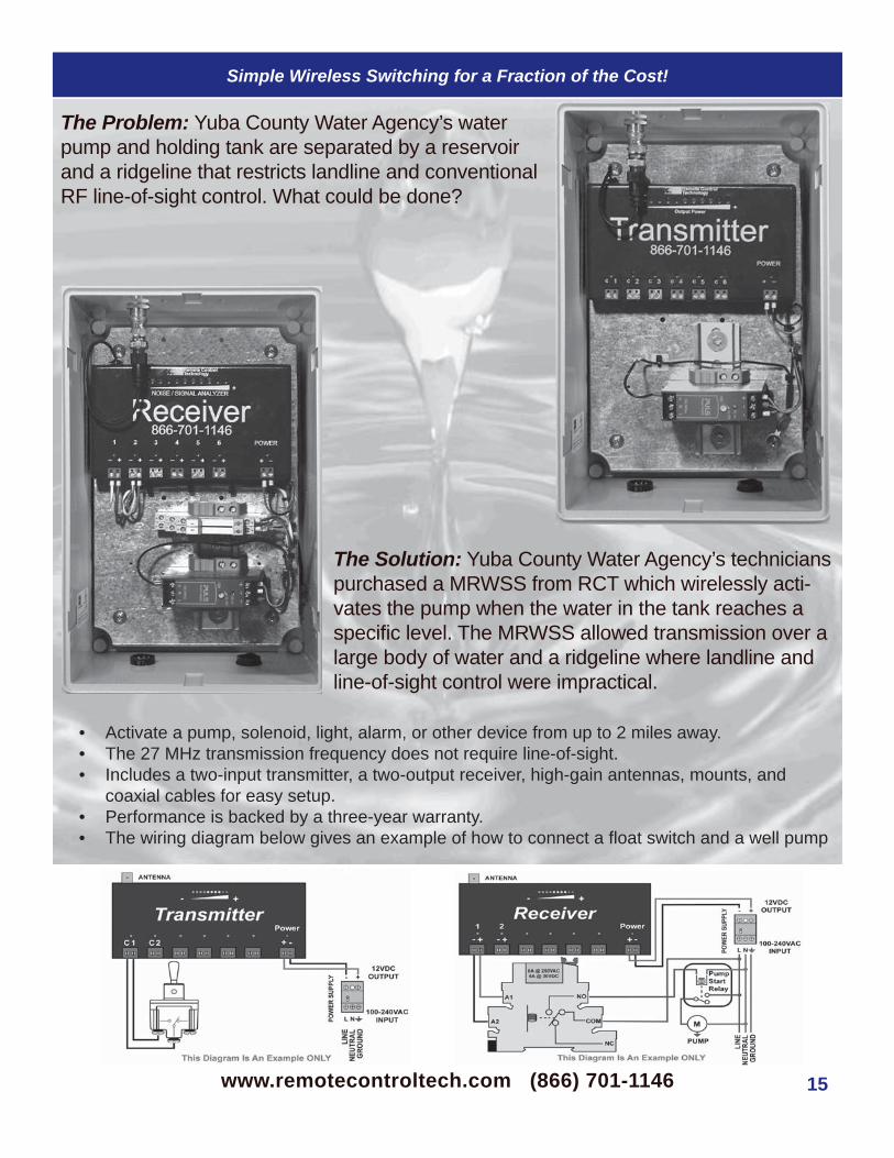
Simple Wireless Switching for a Fraction of the Cost!
The Solution: Yuba County Water Agency’s technicians purchased a MRWSS from RCT which wirelessly acti-vates the pump when the water in the tank reaches a specifi c level. The MRWSS allowed transmission over a large body of water and a ridgeline where landline and line-of-sight control were impractical.
The Problem: Yuba County Water Agency’s waterpump and holding tank are separated by a reservoirand a ridgeline that restricts landline and conventionalRF line-of-sight control. What could be done?
Activate a pump, solenoid, light, alarm, or other device from up to 2 miles away.• The 27 MHz transmission frequency does not require line-of-sight.• Includes a two-input transmitter, a two-output receiver, high-gain antennas, mounts, and •
coaxial cables for easy setup.Performance is backed by a three-year warranty.• The wiring diagram below gives an example of how to connect a fl oat switch and a well pump •

Short Range Wireless Switch System Part #s: 01245, 5810XSThe Short Range Wireless Switch System (SRWSS) is designed for short range (up to ½ mile*) and simple wireless switching. The SRWSS is the simple solution for applications where faulty wire replacement or new installation of conduit is not possible or practical. Possible applications include:
Pump Control• Valve Actuation• Conveyor Control•
Grain Augers• Light Control• Alarm Systems•
PLC Activation• Engine Control• Wireless Automation•
The SRWSS consists of a one or eight-input (12 VDC) transmitter and a one or eight-output (SPDT Class C Relay) receiver. The SRWSS comes complete with power supplies and antennas. Simply make your connections, and the SRWSS is ready for use and guaranteed to perform.
Operation
1 or 8 Dry Contact Input Transmitter Specifi cations
1 or 8 Relay Output Receiver Specifi cations
Applications Include:
Pumps, Valves, Relays, Conveyors, Grain Augers, Alarm Systems, PLC Activation, Stackers, Automation
Phone: (866) 701-1146Fax: (425) 216-7558
www.remotecontroltech.com
www.remotecontroltech.com (866) 701-1146
The SRWSS is designed to be mounted to a wall or in another enclosure; the transmitter is triggered by supplying 12 VDC to the terminal blocks. This sends a coded set of instructions to the receiver. A two-position DIP switch allows the user to select from four modes of operation which control transmission duration. The receiver has several modes of operation. These modes determine how the output(s) function once a properly coded signal is received. A set of DIP switches located next to the microcontroller allows the user to select the mode of operation for the output(s).
Solar Panel Kits: Turnkey, 12 VDC solar panel kits are available for locations without electricity.
Power Requirements
Supply Power: 12 VDC(power supply included)XMIT Current: 300 mASTBY Current: 12 mA
Radio Output: 1 Watt(1/2 mile* potential range)Frequency: 27.195 MHz FMSecurity: Over 4 billion digital codesFCC Part 95 Sub part E compliant(no license required)
Modes of Operation
Mode 1: 2 - 62 second tx repeatMode 2: 1 - 10 min tx repeatMode 3: Continuous 5 min transmitMode 4: 1.5 sec tx burst
Includes:One or eight input transmitter• NEMA 4X plastic enclosure• Power supply• High-gain antenna, mount, and coaxial cable•
Power Requirements
Supply Power: 12 VDC (power supply included)Relay ON Current: 45 mASTBY Current: 10 mA
Radio Frequency: 27.195 MHz FMBandwidth: 25 KHz at -20dBFCC Part 15 compliant(no license required)
Modes of Operation
Relay contact rating: 5A @ 250 VACRelay type: SPDT Class CMode 1: Momentary (MOM)Mode 2: Flip Flop (FF)Mode 3: Latching-On(SRWSS 1 Rx only: Off Delay 1-300 sec)
Includes:One or eight output receiver• Relays with 5A @ 250 VAC Rating• NEMA 4X plastic enclosure• Power supply• High-gain antenna, mount, and coaxial cable•
*The range and performance of all radio products is dependent on local conditions and antenna selection/location.
The SRWSS 27 MHz Radio Signal is not limited by line of sight and can transmit over small buildings and through trees.
SRWSS Transmitter Part #s:Model 27 MHz Inputs
SRWSS 1 TX 01247 1SRWSS 8 TX 5810XT 8
SRWSS Receiver Part #s:Model 27 MHz Inputs
SRWSS 1 RX 01246 1SRWSS 8 RX 5810XR 8
16
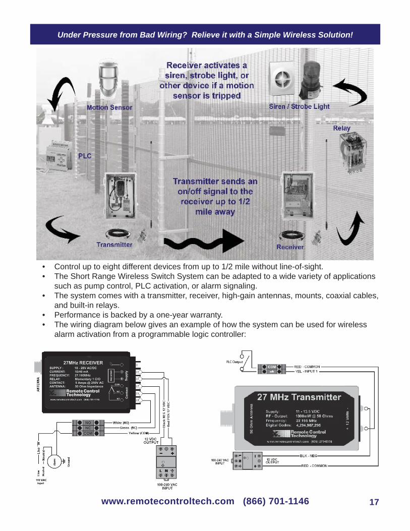
Under Pressure from Bad Wiring? Relieve it with a Simple Wireless Solution!
Control up to eight different devices from up to 1/2 mile without line-of-sight.• The Short Range Wireless Switch System can be adapted to a wide variety of applications •
such as pump control, PLC activation, or alarm signaling.The system comes with a transmitter, receiver, high-gain antennas, mounts, coaxial cables, •
and built-in relays.Performance is backed by a one-year warranty.• The wiring diagram below gives an example of how the system can be used for wireless •
alarm activation from a programmable logic controller:
www.remotecontroltech.com (866) 701-1146 17

Long Range Wireless Switch Sytstem Handheld Part #: 01215
The Long Range Wireless Switch System Handheld (LRWSSHH) is designed for long range and simple wireless switching. In applications where faulty wire replacement or new installation is not possible or practical, the LRWSSHH is the simple solution for:
Pump Control• Valve Actuation• Conveyor Control•
Grain Augers• Light Control• Stackers•
PLC Activation• Engine Control• Wireless Automation•
The LRWSSHH consists of a 12 key hand-held transmitter and a six-output (12 VDC) receiver. Complete with power supply, relays and antennas, simply make your connections and the LRWSSHH is ready for use and guaranteed to perform.
Operation
Handheld Transmitter Specifi cations
16 Relay Output Receiver Specifi cations
Applications Include:
Pumps, Valves, Relays, Conveyors, Grain Augers, Alarm Systems, PLC Activation, Stackers, Automation
Phone: (866) 701-1146Fax: (425) 216-7558
www.remotecontroltech.com
www.remotecontroltech.com (866) 701-1146
Operation is simple: select the receiver output number you wish to activate, enter it on the keypad and press the “ON” key. The transmitter will immediately send an “ON” transmission to the receiver, changing the state of the selected receiver output from 0 VDC to 12 VDC @ 1 Amp. The receiver output will then be used to activate the attached external 12VDC relay. Immediately after pressing the “OFF” key, the transmitter will send an“OFF” transmission to the receiver, changing the state of the selected output from 12 VDC to 0 VDC, deactivating the attached external relay.
Solar Panel Kits: Turnkey, 12 VDC solar panel kits are available for locations without electricity.
Power Requirements
Supply Power: 9 VDC alkaline batteryXMIT Current: 600 mASTBY Current: 1 mA
Radio Output: 2 Watts (2 mile potential range)Frequency: 27.255 MHzFormat: PDTFM FSKFCC Part 95 Sub part E compliant(no license required)
Operating Environment
Indoor or Outdoor32 degrees F to 122 degress F
Includes:Rugged Handheld Aluminum Enclosure• 2-Watt Radio Transmitter • 9 VDC Battery• 8” Whip Antenna• Belt Clip•
Power Requirements
Supply Power: 12 VDC(15 W power supply included)Output Current: 1 amp per outputSTBY Current: 30 mA
Radio Frequency: 27.255 MHz Superheterodyne FM ReceiverFCC Part 15 compliant(no license required)
Operating Environment
Indoor or Outdoor32 degrees F to 122 degress F
LRWSS ReceiverPart #: 01216
Includes:6 Output Receiver• 15-Watt Power Supply (110 VAC to 240 VAC •
Input, 12 VDC Output)NEMA 4X Enclosure• 42” High-gain Antenna• Right-angle Antenna Mount• 25’ Coaxial Cable w/ BNC Connectors•
LRWSSHH TransmitterPart #: 01218
Mounted in a NEMA 4x enclosure, the LRWSSHH system is designed for outdoor/indoor industrial applications. The transmitter itself is housed in a time-tested, rugged aluminum extrusion and is designed to provide years of service. Remote Control Technology backs that up with a three-year warranty. The transmitter has an output power of 2 watts @ 27.255MHz. Potential range is approximately 2 miles and, with proper antenna application, is not limited to line-of-sight communication.
18

Have the Power to Control Any Device in the Palm of Your Hand!
www.remotecontroltech.com (866) 701-1146 19
LRWSS Receiver Wiring Diagram
Simple long range wireless switching made easy with the LRWSSHH. Control anything from conveyors to pumps from a distance of up to 2 miles away.

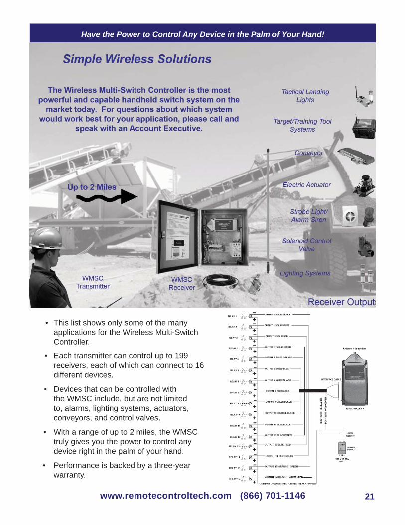
Wireless Multi-Switch Controller Part #: 01260
The Wireless Multi-Switch Controller (WMSC) is designed for long range (up to 2 Miles) and simple wireless switching. The WMSC is the simple solution where faulty wire replacement is required, new installation is not possible or practical, or many different pieces of equipment need to be controlled. Applications for the WMSC include:
Pump Control• Valve Actuation• Conveyor Control•
Grain Augers• Light Control• Stackers•
PLC Activation• Engine Control• Wireless Automation•
The WMSC consists of a 15-key, handheld transmitter and a 16-output (12 VDC), addressable receiver. The WMSC comes complete with power supply and antennas. Simply connect the devices you want to control, and the WMSC is ready for use and guaranteed to perform.
Operation
Handheld Transmitter Specifi cations
16 Relay Output Receiver Specifi cations
Applications Include:
Pumps, Valves, Relays, Conveyors, Grain Augers, Alarm Systems, PLC Activation, Stackers, Automation
Phone: (866) 701-1146Fax: (425) 216-7558
www.remotecontroltech.com
www.remotecontroltech.com (866) 701-1146
Operation is simple: select the receiver number you wish to activate, enter it on the keypad and press the “REC#” key (you can control up to 199 different receivers from one transmitter). Then, select an output to activate, enter it on the keypad and press the “ON” key. the transmitter will immediately send an “ON” transmission to the receiver, changing the state of the selected receiver output from 0 VDC to 12 VDC @ 1 Amp. The receiver output will then be used to activate the attached external 12VDC relay. Immediately after pressing the “OFF” key, the transmitter will send an“OFF” transmission to the receiver, changing the state of the selected output from 12 VDC to 0 VDC, deactivating the attached external relay.
Solar Panel Kits: Turnkey, 12 VDC solar panel kits are available for locations without electricity.
Power Requirements
Supply Power: 9 VDC alkaline batteryXMIT Current: 600 mASTBY Current: 1 mA
Radio Output: 2 Watts (2 mile potential range)Frequency: 26.995 FMFormat: PDTFM FSKFCC Part 95 Sub part E compliant(no license required)
Operating Environment
Indoor or Outdoor32 degrees F to 122 degress F
Includes:Rugged handheld aluminum enclosure• 2-Watt Radio Transmitter • Ability to control up to 199 Receivers• 9 VDC Battery• 8” Whip antenna• Belt clip•
Power Requirements
Supply Power: 12 VDC(15 W power supply included)Output Current: 1 amp per outputSTBY Current: 30 mA
Radio Frequency: 26.995 MHz FMSuperheterodyne FM ReceiverFCC Part 15 compliant(no license required)
Operating Environment
Indoor or Outdoor32 degrees F to 122 degress F
WMSC ReceiverPart #: 01262,01263,01264PaPPPPPPPP
Includes:2, 8 or 16-Output receiver• 15-Watt power supply (110 VAC to 240 VAC •
Input, 12 VDC Output)NEMA 4X Enclosure• 42” High-gain antenna• Right-Angle Antenna Mount• 25’ Coaxial cable w/ BNC connectors• 2, 8 or 16 Class C Relays Rated 6A @ 250V •
WMSC TransmitterPart #: 01261
Mounted in a NEMA 4x enclosure, the WMSC system is designed for outdoor/indoor industrial applications. The transmitter itself is housed in a time-tested, rugged, aluminum extrusion and is designed to provide years of service. Remote Control Technology backs that up with a three-year warranty. The transmitter has an output power of 2 watts @ 26.995 MHz. Potential range is approximately 2 miles, with proper antenna application, is not limited to line-of-sight communication.
20
Have the Power to Control Any Device in the Palm of Your Hand!
This list shows only some of the many • applications for the Wireless Multi-Switch Controller.
Each transmitter can control up to 199 • receivers, each of which can connect to 16 different devices.
Devices that can be controlled with • the WMSC include, but are not limited to, alarms, lighting systems, actuators, conveyors, and control valves.
With a range of up to 2 miles, the WMSC • truly gives you the power to control any device right in the palm of your hand.
Performance is backed by a three-year • warranty.
www.remotecontroltech.com (866) 701-1146 21
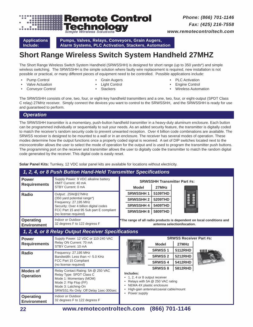
Short Range Wireless Switch System Handheld 27MHZThe Short Range Wireless Switch System Handheld (SRWSSHH) is designed for short range (up to 350 yards*) and simple wireless switching. The SRWSSHH is the simple solution where faulty wire replacement is required, new installation is not possible or practical, or many different pieces of equipment need to be controlled. Possible applications include:
Pump Control• Valve Actuation• Conveyor Control•
Grain Augers• Light Control• Stackers•
PLC Activation• Engine Control• Wireless Automation•
The SRWSSHH consists of one, two, four, or eight-key handheld transmitters and a one, two, four, or eight-output (SPDT Class C relay) 27MHz receiver. Simply connect the devices you want to control to the SRWSSHH, and the SRWSSHH is ready for use and guaranteed to perform.
Operation
1, 2, 4, or 8 Push Button Hand-Held Transmitter Specifi cations
1, 2, 4, or 8 Relay Output Receiver Specifi cations
Applications Include:
Pumps, Valves, Relays, Conveyors, Grain Augers, Alarm Systems, PLC Activation, Stackers, Automation
Phone: (866) 701-1146Fax: (425) 216-7558
www.remotecontroltech.com
www.remotecontroltech.com (866) 701-1146
The SRWSSHH transmitter is a momentary, push-button handheld transmitter in a heavy-duty aluminum enclosure. Each button can be programmed individually or sequentially to suit your needs. As an added security feature, the transmitter is digitally coded to match the receiver’s random security code to prevent unwanted reception. Over 4 billion code combinations are available. The SRWSS receiver is designed to be mounted to a wall or in an enclosure. The receiver has several modes of operation. These modes determine how the output functions once a properly coded signal is received. A set of DIP switches located next to the microcontroller allows the user to select the mode of operation for the output and is used to program the transmitter push buttons. The programming port on the receiver and transmitter allows the user to digitally code the transmitter to match the random digital code generated by the receiver. This digital code is easily reset.
Solar Panel Kits: Turnkey, 12 VDC solar panel kits are available for locations without electricity.
Power Requirements
Supply Power: 9 VDC alkaline batteryXMIT Current: 40 mASTBY Current: 0 mA
Radio Output: .25W@27MHz(350 yard potential range*)Frequency: 27.195 MHzSecurity: Over 4 billion digital codesFCC Part 15 and 95 Sub part E compliant(no license required)
Operating Environment
Indoor or Outdoor32 degrees F to 122 degress F
Power Requirements
Supply Power: 12 VDC or 110-240 VACRelay ON Current: 70 mASTBY Current: 10 mA
Radio Frequency: 27.195 MHzBandwidth: Less than +/- 5.0 KHzFCC Part 15 Compliant(no license required)
Modes of Operation
Relay Contact Rating: 5A @ 250 VACRelay Type: SPDT Class CMode 1: Momentary (MOM)Mode 2: Flip Flop (FF)Mode 3: Latching-OnSRWSS1 Rx Only: Off Delay 1sec-300sec
Operating Environment
Indoor or Outdoor32 degrees F to 122 degress F
SRWSS Receiver Part #s:Model 27MHz
SRWSS 1 5112RHDSRWSS 2 5212RHDSRWSS 4 5412RHDSRWSS 8 5812RHD
Includes:1, 2, 4 or 8 output receiver• Relays with 5A @ 250 VAC rating• NEMA 4X plastic enclosure• High-gain antenna/coaxial cable/mount• Power supply•
*The range of all radio products is dependent on local conditions and antenna selection/location.
SRWSSHH Transmitter Part #s:Model 27MHz
SRWSSHH 1 5109THDSRWSSHH 2 5209THDSRWSSHH 4 5409THDSRWSSHH 8 5809THD
22

Versatility and Mobility, All in One System!
The SRWSSHH is available in 27 MHz for solutions that require non-line-of-sight • operation.
The system consists of a one, two, four, or eight-button handheld transmitter and a one, • two, four, or eight-relay output receiver.
With a range of up to 350 yards, one has the fl exibility to control a wide variety of • devices such as valves, servomotors, pumps, and lights.
Performance backed by a one-year warranty.• The illustration above and the wiring diagram below show how the SRWSSHH can be •
used to control an air-intake shut-off valve on a diesel well drilling rig:
www.remotecontroltech.com (866) 701-1146 23

Short Range Wireless Switch System Handheld 900MHzThe Short Range Wireless Switch System Handheld (SRWSSHH) is designed for short range (up to 350 yards*) and simple wireless switching. The SRWSSHH is the simple solution where faulty wire replacement is required, new installation is not possible or practical, or many different pieces of equipment need to be controlled. Possible applications include:
Pump Control• Valve Actuation• Conveyor Control•
Grain Augers• Light Control• Stackers•
PLC Activation• Engine Control• Wireless Automation•
The SRWSSHH consists of one, two, four, or eight-key handheld transmitters and a one, two, four, or eight-output (SPDT Class C relay) 902-928MHz frequency hopping receiver. Simply connect the devices you want to control to the SRWSSHH, and the SRWSSHH is ready for use and guaranteed to perform.
Operation
1, 2, 4, or 8 Push Button Hand-Held Transmitter Specifi cations
1, 2, 4, or 8 Relay Output Receiver Specifi cations
Applications Include:
Pumps, Valves, Relays, Conveyors, Grain Augers, Alarm Systems, PLC Activation, Stackers, Automation
Phone: (866) 701-1146Fax: (425) 216-7558
www.remotecontroltech.com
www.remotecontroltech.com (866) 701-1146
The Short Range Wireless Switch System (SRWSSHH) 902-928 MHz System uses a 1, 2, 4 or 8 button handheld transmitter and a 1, 2, 4 or 8 output receiver to provide wireless control of multiple devices. The transmitter is used to send a coded set of instructions to the receiver activating corresponding relay outputs. The encrypted coding is a random generated code, which is programmed wirelessly to the transmitter and receiver. Multiple transmitters can be programmed to one receiver and a single transmitter can operate multiple receivers. The receiver output relay has two modes that control how the relays function. The relays are SPDT Class C rated for 5 amps @ 250VAC (or 5A @ 30VDC) with Normally Open (NO), Normally Closed (NC), and a Common (C) contacts. The receivers and transmitters use fast frequency hopping (FFH) to allow up to eight receivers to be used in the same area. No interference or jamming will occur.
Power Requirements
Supply Power: 9 VDC alkaline batteryXMIT Current: 65 mASTBY Current: 0 mA
Radio Output: .25W@902-928MHz(350 yard potential range*)Frequency: 902-928MHz Security: Over 4 billion digital codesFCC Part 15 and 95 Sub part E compliant(no license required)
Operating Environment
Indoor or Outdoor32 degrees F to 122 degress F
Power Requirements
Supply Power: 12 VDC or 110-240 VACRelay ON Current: 70 mASTBY Current: 10 mA
Radio Frequency: 902-928 MHzBandwidth: Less than +/- 5.0 KHzFCC Part 15 Compliant(no license required)
Modes of Operation
Relay Contact Rating: 5A @ 250 VACRelay Type: SPDT Class CMode 1: Momentary (MOM)Mode 2: Flip Flop (FF)
Operating Environment
Indoor or Outdoor32 degrees F to 122 degress F
SRWSS Receiver Part #s:Model 900MHz
SRWSS 1 9112RHDSRWSS 2 9212RHDSRWSS 4 9412RHDSRWSS 8 9812RHD
Includes:1, 2, 4 or 8 output receiver• Relays with 5A @ 250 VAC rating• NEMA 4X plastic enclosure• High-gain antenna/coaxial cable/mount• Power supply•
*The range of all radio products is dependent on local conditions and antenna selection/location.
SRWSSHH Transmitter Part #s:Model 900MHz
SRWSSHH 1 9109THDSRWSSHH 2 9209THDSRWSSHH 4 9409THDSRWSSHH 8 9809THD
24

Versatility and Mobility, All in One System!
The SRWSSHH 902-928MHZ is for solutions that require resistance to electrical noise.• The system consists of a one, two, four, or eight-button handheld transmitter and a one, •
two, four, or eight-relay output receiver. With a range of up to 350 yards, one has the fl exibility to control a wide variety of •
devices such as valves, servomotors, pumps, and lights.Performance backed by a one-year warranty.•
www.remotecontroltech.com (866) 701-1146 25

20 Watt Solar Power System
Applications Include:
Pumps, Valves, Relays, Conveyors, Grain Augers, Alarm Systems, PLC Activation, Stackers, Automation
Phone: (866) 701-1146Fax: (425) 216-7558
www.remotecontroltech.com
www.remotecontroltech.com (866) 701-1146
Power Output Rated Power: 55 wattsRated Voltage: 17.4 VDCRated Current: 3.15 amps
Battery Voltage: 12 VDCCapacity: 65 A hIncludes a NEMA 3R aluminum enclosure
Operating Environment
Outdoor32 degrees F to 122 degress F
Power Output Rated Power: 10 wattsRated Voltage: 16.7 VDCRated Current: .61 ampsNominal Output: 14.3 VDC
Battery Voltage: 12 VDCCapacity: 18 A h @ 20 Hour RateIncludes a NEMA 4X enclosure
Operating Environment
Outdoor32 degrees F to 122 degress F
10 & 20 Watt Solar Power SystemsThe Remote Control Technology 10 W and 20 W Solar Power Systems are complete, fullyintegrated power sources designed to provide 12 VDC. Each system provides safe andreliable power generation without the need and expense of installing utility power. The sealed,maintenance-free battery is designed for deep-cycle operation and extended life in solar powerappplications. The support structure and battery enclosures are strong, lightweight, and corrisionresistant, making them ideal for harsh marine locations or severe weather locations.For Solar Power Systems greater than 20 Watts or for compatibility with systems not listed, callus today at (866) 701-1146.
Part # 09162
Part # 09163
Features and Benefi ts
Solar modules are fully encapsulated to resist harsh • conditions
Low voltage load disconnect for battery protection•
Sealed, lead-acid battery designed for deep • discharge cycling
Corrosion resistant control/battery enclosure•
Outstanding low-light performance•
Heavy-duty annodized frames•
Temperature compensated battery charging•
Solid state electronics for improved effi ciency and • reliability
Pre-assembled, pre-wired systems to minimize installation • time and eliminate wiring errors
Low maintenance and operating cost•
Complete systems reduce specifying and buying time•
Full system and performance warranty available on pre • packaged systems
26
10 Watt Solar Power System
Recommended for use with:
Medium Range Wireless Switch System
Long Range Wireless Switch System
Long Range Handheld System
Wireless Multi-Switch Controller
Panel Dimensions:14.06”w X 22.68h X 1.18dPanel Weight:6.17 lbsEnclosure Dimensions:12”h X 10”w X 8”dBattery Dimensions:7.72”hX 5.14”w X 7.00”dBattery Weight24.74lbs
Recommended for use with:
Short Range Wireless Switch System
• Stationary One Channel• Stationary Eight Channel
Short Range Handheld Sys-tem Receivers
Panel Dimensions:14.06”h X 11.89’’w X 1.18”dPanel Weight:3.53lbsEnclosure Dimensions:12”h X 10”w X 8”dBattery Dimensions:7.31”hX 3.0”w X 6.59”dBattery Weight:12.60lbs

Harness the Power of the Sun!
The 10 and 20 watt solar power systems are fully integrated power sources that supply • 12 VDC to your Remote Control Technology Simple Wireless Solution and the devices that you are monitoring or controlling.
These systems are ruggedly built to withstand the rigors of extended operation in remote • locations and require virtually no maintenance after inital installation.
The wiring diagram below demonstrates how the Solar Power Sytstems integrate with your • transimitter, receiver, or device:
www.remotecontroltech.com (866) 701-1146 27

AntennasChoosing the correct antenna and location for your Wireless Switch System is a critical factor in determining how well the system will perform. While there are many antennas on the market, Remote Control Technology can provide the options that work best with our products.
ANTENNAS
Applications Include:
Pumps, Valves, Relays, Conveyors, Grain Augers, Alarm Systems, PLC Activation, Stackers, Automation
Phone: (866) 701-1146Fax: (425) 216-7558
www.remotecontroltech.com
www.remotecontroltech.com (866) 701-1146
The range of all radio products is dependent on local conditions and antenna selection/location.
ANTENNA INSTALLATION
Successful wireless communication range is achievable in most locations as long as the following installation practices are observed. Remote Control Technology can supply connectors and RG-58 coaxial cable in lengths of 3, 10, 25, 50, and 100 feet (specify when ordering). Your range will be maximized by following these guidelines:
Mount the antennas at least 40 feet away from electric motors, large power transformers, power • lines, VFDs or any equipment that produces ambient electrical noise. Otherwise, the receiver may have trouble distinguishing the FM transmitter signal from this noise.
When using 27 MHz systems, mount all antennas outdoors. This frequency has great • characteristics for long range, but the signals will not go through metal-reinforced concrete walls. For equipment located indoors, run a length of RG-58 coaxial cable from the receiver to an antenna mounted outdoors.
When using 902-928 MHz systems, be sure that the antennas have a line-of-sight (a • straight line could be drawn between the antennas without going through any solid objects). These systems are recomended for all indoor applications.
Mount antennas as high as possible, at least 3 feet away from vertical surfaces, and above • awnings.
Use only high-quality cables and connectors, which are available from RCT. • Do not loop excess coaxial cable into a coil. This will cause a radio frequency choke and •
reduce your signal range. Loosely route it back and forth in an “S” confi guration.
8” Short-Range Flexible Whip Antenna for 27 MHz, Part #:
01610
8” Mid-Range Tuned Antenna for 27 MHz, Part #: 01943 (Requires
mounting bracket and ground plane)
42” Long-Range Francis Antenna for 27 MHz, Part # 01940 (Requires mounting
bracket and ground plane)
Short-Range Antenna for 902-928 MHz
Long-Range Antenna for 433 MHz, Part #: 01948 (Includes mounting bracket
and coaxial cable)
28

From Simple Switching... To Data Monitoring... To Custom Products...
Remote Control Technology designs and manufactures Radio Frequency devices for all your wireless data and
switching needs.
Simple Wireless Solutions
14736 NE 95th StRedmond, WA 98052
Toll Free: (866) 701-1146(425) 216-7555
Fax: (425) 216-7558
www.remotecontroltech.com