
Procise® Protein Sequencing Systemtools.thermofisher.com/content/sfs/manuals/cms_041126.pdf · The...
66
Procise ® Protein Sequencing System Basic Operation Manual
Transcript of Procise® Protein Sequencing Systemtools.thermofisher.com/content/sfs/manuals/cms_041126.pdf · The...

Procise®
Protein Sequencing System
Basic Operation Manual

© Copyright 2000, 2002. Applied Biosystems
For Research Use Only. Not for use in diagnostic procedures.
Applied Biosystems and Procise are registered trademarks of Applera Corporation or its subsidiaries in the U.S. and certain other countries.
BioBrene and SequencePro are trademarks of Applera Corporation or its subsidiaries in the U.S. and certain other countries.
Microsoft, Windows, and Windows NT are registered trademarks of Microsoft Corporation in the United States and/or other countries.
All other trademarks are the sole property of their respective owners.
Applera Corporation is committed to providing the world’s leading technology and information for life scientists. Applera Corporation consists of the Applied Biosystems and Celera Genomics businesses.
Contents
1 IntroductionOverview . . . . . . . . . . . . . . . . . . . . . . . . . . . . . . . . . . . . . . . . . . . . . . . . . . . . . . . . . . . . . . . . . . 1-1
Product Overview . . . . . . . . . . . . . . . . . . . . . . . . . . . . . . . . . . . . . . . . . . . . . . . . . . . . . . . . . . . . 1-2
Safety . . . . . . . . . . . . . . . . . . . . . . . . . . . . . . . . . . . . . . . . . . . . . . . . . . . . . . . . . . . . . . . . . . . . . 1-4
2 Sequencer SetupOverview . . . . . . . . . . . . . . . . . . . . . . . . . . . . . . . . . . . . . . . . . . . . . . . . . . . . . . . . . . . . . . . . . . 2-1
Basic Connections . . . . . . . . . . . . . . . . . . . . . . . . . . . . . . . . . . . . . . . . . . . . . . . . . . . . . . . . . . . 2-2
Pressures and Temperatures . . . . . . . . . . . . . . . . . . . . . . . . . . . . . . . . . . . . . . . . . . . . . . . . . . . . 2-5
Sequencer Reagents and Solvents . . . . . . . . . . . . . . . . . . . . . . . . . . . . . . . . . . . . . . . . . . . . . . . 2-6
Bottle Change . . . . . . . . . . . . . . . . . . . . . . . . . . . . . . . . . . . . . . . . . . . . . . . . . . . . . . . . . . . . . . . 2-7
PTH-Amino Acid Standard . . . . . . . . . . . . . . . . . . . . . . . . . . . . . . . . . . . . . . . . . . . . . . . . . . . . 2-9
BioBrene Plus Solution . . . . . . . . . . . . . . . . . . . . . . . . . . . . . . . . . . . . . . . . . . . . . . . . . . . . . . 2-10
ß-lactoglobulin Solution . . . . . . . . . . . . . . . . . . . . . . . . . . . . . . . . . . . . . . . . . . . . . . . . . . . . . . 2-11
Waste Bottle . . . . . . . . . . . . . . . . . . . . . . . . . . . . . . . . . . . . . . . . . . . . . . . . . . . . . . . . . . . . . . . 2-12
3 HPLC SetupOverview . . . . . . . . . . . . . . . . . . . . . . . . . . . . . . . . . . . . . . . . . . . . . . . . . . . . . . . . . . . . . . . . . . 3-1
Preparing Solvents . . . . . . . . . . . . . . . . . . . . . . . . . . . . . . . . . . . . . . . . . . . . . . . . . . . . . . . . . . . 3-2
Replacing Solvents . . . . . . . . . . . . . . . . . . . . . . . . . . . . . . . . . . . . . . . . . . . . . . . . . . . . . . . . . . . 3-4
Changing the Column . . . . . . . . . . . . . . . . . . . . . . . . . . . . . . . . . . . . . . . . . . . . . . . . . . . . . . . . 3-6
Gradient Programming . . . . . . . . . . . . . . . . . . . . . . . . . . . . . . . . . . . . . . . . . . . . . . . . . . . . . . . . 3-8
Optimizing the PTH-Amino Acid Separation . . . . . . . . . . . . . . . . . . . . . . . . . . . . . . . . . . . . . 3-12
4 Sequencer OperationOverview . . . . . . . . . . . . . . . . . . . . . . . . . . . . . . . . . . . . . . . . . . . . . . . . . . . . . . . . . . . . . . . . . . 4-1
Standard Sequencing Methods . . . . . . . . . . . . . . . . . . . . . . . . . . . . . . . . . . . . . . . . . . . . . . . . . . 4-2
Loading Reaction Cartridges . . . . . . . . . . . . . . . . . . . . . . . . . . . . . . . . . . . . . . . . . . . . . . . . . . . 4-5
Starting a Run . . . . . . . . . . . . . . . . . . . . . . . . . . . . . . . . . . . . . . . . . . . . . . . . . . . . . . . . . . . . . . . 4-9
Data Collection. . . . . . . . . . . . . . . . . . . . . . . . . . . . . . . . . . . . . . . . . . . . . . . . . . . . . . . . . . . . . 4-11
Sequencer Idle Time. . . . . . . . . . . . . . . . . . . . . . . . . . . . . . . . . . . . . . . . . . . . . . . . . . . . . . . . . 4-13
A Getting HelpOverview . . . . . . . . . . . . . . . . . . . . . . . . . . . . . . . . . . . . . . . . . . . . . . . . . . . . . . . . . . . . . . . . . .A-1
Technical Support . . . . . . . . . . . . . . . . . . . . . . . . . . . . . . . . . . . . . . . . . . . . . . . . . . . . . . . . . . . .A-2
iii

B WarrantyApplied Biosystems Limited Warranty Statement . . . . . . . . . . . . . . . . . . . . . . . . . . . . . . . . . . B-1
Index
iv

1
Introduction 1Overview
About This Chapter This chapter provides an overview of the four modules of the Procise® Protein Sequencing System as well as important safety information.
In This Chapter This chapter contains the following topics:
Topic See Page
Product Overview 1-2
Safety 1-4
Introduction 1-1
Product Overview
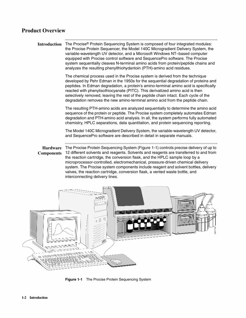
Introduction The Procise® Protein Sequencing System is composed of four integrated modules: the Procise Protein Sequencer, the Model 140C Microgradient Delivery System, the variable-wavelength UV detector, and a Microsoft Windows NT–based computer equipped with Procise control software and SequencePro software. The Procise system sequentially cleaves N-terminal amino acids from protein/peptide chains and analyzes the resulting phenylthiohydantoin (PTH)-amino acid residues.
The chemical process used in the Procise system is derived from the technique developed by Pehr Edman in the 1950s for the sequential degradation of proteins and peptides. In Edman degradation, a protein's amino-terminal amino acid is specifically reacted with phenylisothiocyanate (PITC). This derivatized amino acid is then selectively removed, leaving the rest of the peptide chain intact. Each cycle of the degradation removes the new amino-terminal amino acid from the peptide chain.
The resulting PTH-amino acids are analyzed sequentially to determine the amino acid sequence of the protein or peptide. The Procise system completely automates Edman degradation and PTH-amino acid analysis. In all, the system performs fully automated chemistry, HPLC separations, data quantitation, and protein sequencing reporting.
The Model 140C Microgradient Delivery System, the variable-wavelength UV detector, and SequencePro software are described in detail in separate manuals.
HardwareComponents
The Procise Protein Sequencing System (Figure 1-1) controls precise delivery of up to 12 different solvents and reagents. Solvents and reagents are transferred to and from the reaction cartridge, the conversion flask, and the HPLC sample loop by a microprocessor-controlled, electromechanical, pressure-driven chemical delivery system. The Procise system components include reagent and solvent bottles, delivery valves, the reaction cartridge, conversion flask, a vented waste bottle, and interconnecting delivery lines.
Figure 1-1 The Procise Protein Sequencing System
1-2 Introduction

Software The Procise control software regulates and monitors the functions of the Procise system. The Procise control software allows the user to create and select sequencer functions, gradients, cycles, and methods, and constantly monitor the chemistry cycles and overall operation of the instrument.
Standard automated sequencing cycles and methods are supplied as part of the software package. A cycle is a programmed series of steps designed to deliver reagents and solvents to carry out the Edman degradation. The user can modify these cycles to create individualized protocols. The Procise Protein Sequencing System Advanced Operation Manual (P/N 4314375) lists the cycles and describes how the microprocessor controls the hardware.
The Sequencing Run During sequencing, the sample is retained on a solid support (such as a glass-fiber disk) in a temperature-controlled glass reaction cartridge. At the end of each degradation cycle, the terminal amino acid is removed as an anilinothiazolinone amino acid (ATZ-AA) derivative. The ATZ-AA derivative is automatically transferred from the reaction cartridge to a separately heated conversion flask for further derivatization to the more stable phenylthiohydantoin-amino acid (PTH-AA). The PTH-AAs are then transferred from the conversion flask to the injection valve for subsequent separation and quantitation.
PTH-AA Detection The Model 140C Microgradient Delivery System is a dual-syringe, gradient-programmable microbore HPLC system connected to a low-noise, high-sensitivity, variable-wavelength UV/VIS detector. A reversed-phase analytical column in a temperature-controlled heating block is used to separate the PTH-AAs. Because the different PTH-AAs have unique relative affinities for the column, the PTH-AAs exit the column at different times.
The Procise Advanced Operation Manual describes how to use the HPLC system, adjust the PTH-AA separation, prepare and change the mobile phase, and change a column.
Data Collection The output from the HPLC detector is collected by the Procise control software. A 24-bit A/D converter onboard the sequencer converts the analog signal to a digital signal and transmits the digital signal to the SequencePro software. SequencePro software is data acquisition software for collection, storage, analysis, and reporting of protein/peptide sequence data. SequencePro software is described in detail in the SequencePro User’s Manual (P/N 905007).
Note The Procise Protein Sequencing System is intended for research use only. It is not to be used for reporting patient diagnostic or therapeutic results.
Introduction 1-3

Safety\
Documentation UserAttention Words
Five user attention words appear in the text of all Applied Biosystems user documentation. Each word implies a particular level of observation or action as described below.
Note Calls attention to useful information.
IMPORTANT Indicates information that is necessary for proper instrument operation.
Cautions the user that a potentially hazardous situation could occur, causing injury to the user or damage to the instrument if this information is ignored.
Warns the user that serious physical injury or death to the user or other persons could result if these precautions are not taken.
Indicates an imminently hazardous situation that, if not avoided, will result in death or serious injury.
Chemical HazardWarning
CHEMICAL HAZARD. Some of the chemicals used with Applied Biosystems instruments and protocols are potentially hazardous and can cause injury, illness, or death.
� Read and understand the material safety data sheets (MSDSs) provided by the chemical manufacturer before you store, handle, or work with any chemicals or hazardous materials.
� Minimize contact with and inhalation of chemicals. Wear appropriate personal protective equipment when handling chemicals (e.g., safety glasses, gloves, or protective clothing). For additional safety guidelines, consult the MSDS.
� Do not leave chemical containers open. Use only with adequate ventilation.
� Check regularly for chemical leaks or spills. If a leak or spill occurs, follow the manufacturer’s cleanup procedures as recommended on the MSDS.
� Comply with all local, state/provincial, or national laws and regulations related to chemical storage, handling, and disposal.
Chemical WasteHazard Warning
CHEMICAL WASTE HAZARD. Wastes produced by Applied Biosystems instruments are potentially hazardous and can cause injury, illness, or death.
� Read and understand the material safety data sheets (MSDSs) provided by the manufacturers of the chemicals in the waste container before you store, handle, or dispose of chemical waste.
� Handle chemical wastes in a fume hood.
� Minimize contact with and inhalation of chemical waste. Wear appropriate personal protective equipment when handling chemicals (e.g., safety glasses, gloves, or protective clothing).
� After emptying the waste container, seal it with the cap provided.
� Dispose of the contents of the waste tray and waste bottle in accordance with good laboratory practices and local, state/provincial, or national environmental and health regulations.
CAUTION!
WARNING!
DANGER!
WARNING!
WARNING!
1-4 Introduction

\
Chemical Warnings Potentially hazardous chemicals used on the Procise system are discussed in Table 1-1.
Table 1-1 Warnings on Chemicals Used in the Procise System
Chemical Chemical Hazard
A3 (3.5% tetrahydrofuran in water)
CHEMICAL HAZARD. A3 (tetrahydrofuran in water) is a flammable liquid and vapor. It may be harmful if swallowed. Exposure may cause eye and respiratory tract irritation, central nervous system depression, and liver and kidney damage. Please read the MSDS and follow the handling instructions. Wear appropriate protective eyewear, clothing, and gloves.
Acetone CHEMICAL HAZARD. Acetone is a flammable liquid and vapor. It may cause eye, skin, and upper respiratory tract irritation. Prolonged or repeated contact may dry skin. It may cause central nervous system effects such as drowsiness, dizziness, headache, etc. Please read the MSDS and follow the handling instructions. Wear appropriate protective eyewear, clothing, and gloves.
Acetonitrile
(Also in R5, S4B, B2)
CHEMICAL HAZARD. Acetonitrile is a flammable liquid and vapor. It may cause eye, skin, and respiratory tract irritation, central nervous system depression, and heart, liver, and kidney damage. Please read the MSDS and follow the handling instructions. Wear appropriate protective eyewear, clothing, and gloves.
Argon CHEMICAL HAZARD. Argon is a nonflammable high-pressure gas. Released argon gas reduces the oxygen available for breathing. Please read the MSDS and follow the handling instructions. Wear appropriate protective eyewear, clothing, and gloves.
B2 (12% isopropanol and acetonitrile)
CHEMICAL HAZARD. B2 (12% isopropanol and acetonitrile) is a flammable liquid and vapor. It may cause eye, skin, and respiratory tract irritation. Prolonged or repeated contact may dry skin. Exposure may cause central nervous system depression, and heart, liver, and kidney damage. Please read the MSDS and follow the handling instructions. Wear appropriate protective eyewear, clothing, and gloves.
Biobrene Plus Reagent CHEMICAL HAZARD. Biobrene Plus may cause eye, skin, and respiratory tract irritation. Please read the MSDS and follow the handling instructions. Wear appropriate protective eyewear, clothing, and gloves.
Dithiothreitol (DTT)
(In R4A, R5)
CHEMICAL HAZARD. Dithiothreitol (DTT) may cause eye, skin, and respiratory tract irritation, central nervous system depression, and damage to the kidneys. Please read the MSDS and follow the handling instructions. Wear appropriate protective eyewear, clothing, and gloves.
Isopropanol CHEMICAL HAZARD. Isopropyl alcohol can be harmful if inhaled, ingested, or absorbed through the skin. It can cause CNS depression, and be irritating to the eyes, skin, and mucous membranes.
WARNING!
WARNING!
WARNING!
CAUTION!
WARNING!
CAUTION!
CAUTION!
WARNING!
Introduction 1-5
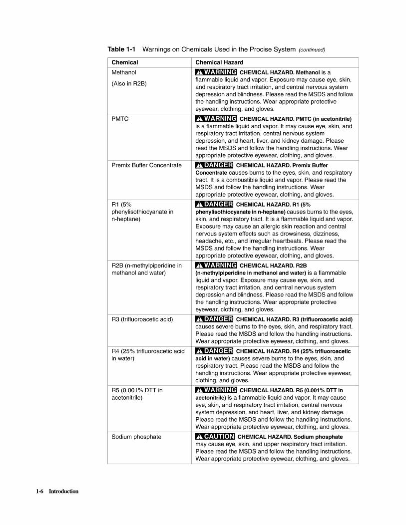
Methanol
(Also in R2B)
CHEMICAL HAZARD. Methanol is a flammable liquid and vapor. Exposure may cause eye, skin, and respiratory tract irritation, and central nervous system depression and blindness. Please read the MSDS and follow the handling instructions. Wear appropriate protective eyewear, clothing, and gloves.
PMTC CHEMICAL HAZARD. PMTC (in acetonitrile) is a flammable liquid and vapor. It may cause eye, skin, and respiratory tract irritation, central nervous system depression, and heart, liver, and kidney damage. Please read the MSDS and follow the handling instructions. Wear appropriate protective eyewear, clothing, and gloves.
Premix Buffer Concentrate CHEMICAL HAZARD. Premix Buffer Concentrate causes burns to the eyes, skin, and respiratory tract. It is a combustible liquid and vapor. Please read the MSDS and follow the handling instructions. Wear appropriate protective eyewear, clothing, and gloves.
R1 (5% phenylisothiocyanate in n-heptane)
CHEMICAL HAZARD. R1 (5% phenylisothiocyanate in n-heptane) causes burns to the eyes, skin, and respiratory tract. It is a flammable liquid and vapor. Exposure may cause an allergic skin reaction and central nervous system effects such as drowsiness, dizziness, headache, etc., and irregular heartbeats. Please read the MSDS and follow the handling instructions. Wear appropriate protective eyewear, clothing, and gloves.
R2B (n-methylpiperidine in methanol and water)
CHEMICAL HAZARD. R2B (n-methylpiperidine in methanol and water) is a flammable liquid and vapor. Exposure may cause eye, skin, and respiratory tract irritation, and central nervous system depression and blindness. Please read the MSDS and follow the handling instructions. Wear appropriate protective eyewear, clothing, and gloves.
R3 (trifluoroacetic acid) CHEMICAL HAZARD. R3 (trifluoroacetic acid) causes severe burns to the eyes, skin, and respiratory tract. Please read the MSDS and follow the handling instructions. Wear appropriate protective eyewear, clothing, and gloves.
R4 (25% trifluoroacetic acid in water)
CHEMICAL HAZARD. R4 (25% trifluoroacetic acid in water) causes severe burns to the eyes, skin, and respiratory tract. Please read the MSDS and follow the handling instructions. Wear appropriate protective eyewear, clothing, and gloves.
R5 (0.001% DTT in acetonitrile)
CHEMICAL HAZARD. R5 (0.001% DTT in acetonitrile) is a flammable liquid and vapor. It may cause eye, skin, and respiratory tract irritation, central nervous system depression, and heart, liver, and kidney damage. Please read the MSDS and follow the handling instructions. Wear appropriate protective eyewear, clothing, and gloves.
Sodium phosphate CHEMICAL HAZARD. Sodium phosphate may cause eye, skin, and upper respiratory tract irritation. Please read the MSDS and follow the handling instructions. Wear appropriate protective eyewear, clothing, and gloves.
Table 1-1 Warnings on Chemicals Used in the Procise System (continued)
Chemical Chemical Hazard
WARNING!
WARNING!
DANGER!
DANGER!
WARNING!
DANGER!
DANGER!
WARNING!
CAUTION!
1-6 Introduction

Site Preparation andSafety Guide
A site preparation and safety guide is a separate document sent to all customers who have purchased an Applied Biosystems instrument. Refer to the guide written for your instrument for information on site preparation, instrument safety, chemical safety, and waste profiles.
S1 (n-heptane) CHEMICAL HAZARD. S1 (n-heptane) is a flammable liquid and vapor. It may cause eye, skin, and respiratory tract irritation. Prolonged or repeated contact may dry skin. It may cause central nervous system effects such as drowsiness, dizziness, headache, etc., and irregular heartbeats. Please read the MSDS and follow the handling instructions. Wear appropriate protective eyewear, clothing, and gloves.
S2B (ethyl acetate) CHEMICAL HAZARD. S2B (ethyl acetate) is a flammable liquid and vapor. It may cause eye, skin, and respiratory tract irritation. Prolonged or repeated contact may dry skin. It may cause central nervous system effects such as drowsiness, dizziness, headache, etc. Please read the MSDS and follow the handling instructions. Wear appropriate protective eyewear, clothing, and gloves.
S3 (n-butyl chloride) CHEMICAL HAZARD. S3 (n-butyl chloride) is a flammable liquid and vapor. Exposure may cause central nervous system effects such as drowsiness, dizziness, headache, etc. Please read the MSDS and follow the handling instructions. Wear appropriate protective eyewear, clothing, and gloves.
S4B (20% acetonitrile in water)
CHEMICAL HAZARD. S4B (20% acetonitrile in water) is a flammable liquid and vapor. It may cause eye, skin, and respiratory tract irritation, central nervous system depression, and heart, liver, and kidney damage. Please read the MSDS and follow the handling instructions. Wear appropriate protective eyewear, clothing, and gloves.
Sodium dodecyl sulfate (SDS)
CHEMICAL HAZARD. Sodium dodecyl sulfate (SDS) may cause an allergic respiratory reaction. It is harmful if inhaled, swallowed, or absorbed through the skin. Exposure causes eye, skin, and respiratory tract irritation. Please read the MSDS and follow the handling instructions. Wear appropriate protective eyewear, clothing, and gloves.
Table 1-1 Warnings on Chemicals Used in the Procise System (continued)
Chemical Chemical Hazard
WARNING!
WARNING!
WARNING!
WARNING!
WARNING!
Introduction 1-7

About MSDSs Some of the chemicals used with this instrument may be listed as hazardous by their manufacturer. When hazards exist, warnings are prominently displayed on the labels of all chemicals.
Chemical manufacturers supply a current MSDS before or with shipments of hazardous chemicals to new customers and with the first shipment of a hazardous chemical after an MSDS update. MSDSs provide you with the safety information you need to store, handle, transport and dispose of the chemicals safely.
We strongly recommend that you replace the appropriate MSDS in your files each time you receive a new MSDS packaged with a hazardous chemical.
CHEMICAL HAZARD. Be sure to familiarize yourself with the MSDSs before using reagents or solvents.
Ordering MSDSs You can order free additional copies of MSDSs for chemicals manufactured or distributed by Applied Biosystems using the contact information below.
For chemicals not manufactured or distributed by Applied Biosystems, call the chemical manufacturer.
Instrument SafetyLabels
Safety labels are located on the instrument. Each Safety label consists of a:
� Signal Word panel, which implies a particular level of observation or action (e.g., CAUTION or WARNING). If a safety label encompasses multiple hazards, the Signal Word corresponding to the greatest hazard is used.
� Message panel, which explains the hazard and any user action required.
� Safety Alert symbol, which indicates a potential personal safety hazard. See the Procise/Procise cLC Protein Sequencing Systems Site Preparation and Safety
WARNING!
To order MSDSs... Then...
Over the Internet Go to our web site at: www.appliedbiosystems.com/techsupport
a. Click on MSDSs
b. Enter keywords (or partial words), or a part number, or the MSDSs Documents on Demand index number.
c. Click on Search
d. Click on the Adobe Acrobat symbol to view, print, or download the document, or check the box of the desired document and delivery method (fax or e-mail)
By automated telephone service from any country
Use “To Obtain Documents on Demand” on page A-5.
By telephone in the United States
Dial 1-800-327-3002, then press 1
By telephone from Canada
By telephone from any other country
See “Technical Support” on page A-2.
To order in... Then dial 1-800-668-6913 and...
English Press 1, then 2, then 1 again
French Press 2, then 2, then 1
1-8 Introduction

Guide (P/N 4314377) for an explanation of all Safety Alert symbols provided in multiple languages.
About Waste Profiles A waste profile was provided with this instrument and is contained in the Procise and Procise cLC Site Preparation and Safety Guide. Waste profiles list the percentage compositions of the reagents within the waste stream at installation and the waste stream during a typical user application. These profiles assist users in planning for instrument waste handling and disposal, which must be in accordance with local, state/provincial, or national regulations. Read the waste profiles and all applicable MSDSs before handling or disposing of waste.
IMPORTANT Waste profiles are not a substitute for MSDS information.
About WasteDisposal
As the generator of potentially hazardous waste, it is your responsibility to perform the actions listed below.
� Characterize (by analysis if necessary) the waste generated by the particular applications, reagents, and substrates used in your laboratory.
� Ensure the health and safety of all personnel in your laboratory.
� Ensure that the instrument waste is stored, transferred, transported, and disposed of according to all local, state/provincial, or national regulations.
Radioactive or biohazardous materials may require special handling, and disposal limitations may apply.
Before Operating theInstrument
Ensure that everyone involved with the operation of the instrument has:
� Received instruction in general safety practices for laboratories
� Received instruction in specific safety practices for the instrument
� Read and understood all related MSDSs
Avoid using this instrument in a manner not specified by Applied Biosystems. Although the instrument has been designed to protect the user, this protection can be impaired if the instrument is used improperly.
Safe and EfficientComputer Use
Operating the computer correctly prevents stress-producing effects such as fatigue, pain, and strain.
In order to minimize these effects on your back, legs, eyes, and upper extremities (neck, shoulder, arms, wrists, hands and fingers), design your workstation to promote neutral or relaxed working positions. This includes working in an environment where heating, air conditioning, ventilation, and lighting are set correctly. See the guidelines below.
MUSCULOSKELETAL AND REPETITIVE MOTION HAZARD. These hazards are caused by the following potential risk factors which include, but are not limited to, repetitive motion, awkward posture, forceful exertion, holding static unhealthy positions, contact pressure, and other workstation environmental factors.
� Use a seating position that provides the optimum combination of comfort, accessibility to the keyboard, and freedom from fatigue-causing stresses and pressures. Three basic requirements are:
CAUTION!
CAUTION!
Introduction 1-9

– The bulk of the person’s weight should be supported by the buttocks, not the thighs.
– Feet should be flat on the floor and the weight of the legs should be supported by the floor, not the thighs.
– Lumbar support should be provided to maintain the proper concave curve of the spine.
� Place the keyboard on a surface that provides:
– The proper height to position the forearms horizontally and upper arms vertically.
– Support for the forearms and hands to avoid muscle fatigue in the upper arms.
� Position the viewing screen to the height that allows normal body and head posture. This height depends upon the physical proportions of the user.
� Adjust vision factors to optimize comfort and efficiency by:
– Adjusting screen variables, such as brightness, contrast, and color, to suit personal preferences and ambient lighting.
– Positioning the screen to minimize reflections from ambient light sources.
– Positioning the screen at a distance that takes into account user variables such as nearsightedness, farsightedness, astigmatism, and the effects of corrective lenses.
� When considering the user’s distance from the screen, the following are useful guidelines:
– The distance from the user’s eyes to the viewing screen should be approximately the same as the distance from the user’s eyes to the keyboard.
– For most people, the reading distance that is the most comfortable is approximately 20 inches.
– The workstation surface should have a minimum depth of 36 inches to accommodate distance adjustment.
– Adjust the screen angle to minimize reflection and glare, and avoid highly reflective surfaces for the workstation.
� Use a well-designed copy holder, adjustable horizontally and vertically, that allows referenced hard copy material to be placed at the same viewing distance as the screen and keyboard.
� Keep wires and cables out of the way of users and passers-by.
� Choose a workstation that has a surface large enough for other tasks and that provides sufficient leg room for adequate movement.
1-10 Introduction

2
Sequencer Setup 2Overview
About This Chapter This chapter describes how to prepare the Procise® Protein Sequencing System for operation, including the necessary physical connections and reagent/solvent preparation. Detailed explanations of the sequencing chemistry can be found in the Procise Protein Sequencing System Advanced Operation Manual.
In This Chapter This chapter contains the following topics:
Topic See Page
Basic Connections 2-2
Pressures and Temperatures 2-5
Sequencer Reagents and Solvents 2-6
Bottle Change 2-7
PTH-Amino Acid Standard 2-9
BioBrene Plus Solution 2-10
ß-lactoglobulin Solution 2-11
Waste Bottle 2-12
Sequencer Setup 2-1

Basic Connections
About Connections During installation, all the correct physical connections are made by your Applied Biosystems Service Representative. If the instrument is moved or shut down for an extended period of time, review this section to ensure that all the necessary connections are made before restarting the sequencer.
ElectricalConnections
A power strip with four power connections is provided with the standard Procise system. Additional connections may be needed for optional modules, such as a chart recorder. It is recommended that the instrument have a dedicated electrical line with a circuit breaker. The outlet must be located within 2.5 m (8 ft) of the instrument. For additional details, see the Procise/Procise c/LC Protein Sequencing Systems Site Preparation and Safety Guide (P/N 4314377).
The Procise system has an automatic line-switching power supply that accepts an ac voltage between 90 and 264 Vac at a frequency of 50 or 60 Hz. The Microsoft Windows NT–based computer for system control and data analysis has an automatic switching power supply and operates between 90 and 264 Vac at a frequency of 50 or 60 Hz. The Model 140C pump and the UV detector come with the correct voltage configuration kit for the particular country (either 100, 120, 220, or 240 Vac).
CommunicationConnections
Communication connections for the Procise system are shown in Figure 2-1. Make sure that the line connecting the Procise sequencer and the computer is connected to the serial port #1 of the computer.
If a chart recorder with an external paper feed control is being used, connect the respective pins to the two Event 1 terminals on the rear connection strip of the Model 140C pump. Set the chart recorder to auto-paper feed with a chart speed of 5 mm/min.
2-2 Sequencer Setup

Figure 2-1 Communication Connections
Argon SupplyConnections
Use only prepurified argon of 99.998% purity or greater.
At least one size 1A cylinder of prepurified argon is required to supply inert gas to the Procise system. A regulator and a CGA 580 cylinder-adapter are required for each argon gas cylinder in order to control the inert gas supply to the instrument. The exit side of the regulator should have Swagelok-type end fittings for connection to 1/4-inch (6.355 mm) o.d. tubing. The regulator should be set between 65 and 75 psi (448 and 517 kPa). If the input pressure drops below 60 psi during sequencing, the system pauses.
EXPLOSION HAZARD. Ensure that the pressurized gas cylinder is safely attached to the wall or table/bench by means of approved brackets or chains. Failure to do so could cause the cylinder to fall over and explode. Always turn off, cap, and secure any cylinder that is not in use.
CAUTION!
WARNING!
Sequencer Setup 2-3

PlumbingConnections
The Procise system is properly plumbed and ready for operation after the installation is complete. Figure 2-2 shows the plumbing connections for this system.
Figure 2-2 Plumbing Connections
Note Bottles for Solvents A and B and the two waste bottles must be placed inside secondary containments. Secondary containments are trays which hold free-standing bottles and contain any spills.
2-4 Sequencer Setup

Pressures and Temperatures
Setting Pressuresand Temperatures
Pressures and temperatures for the Procise system are set and adjusted from the Pressures & Temperatures window.
To set pressures and temperatures:
Step Action
1 Access the Pressures & Temperatures window.
(The pressures shown are not the defaults.)
2 To change the pressure settings:
a. Highlight the appropriate numerical entry field under Pressures.
b. Type in the new value.
c. Click Execute.
(Appropriate entries for pressures are values between 0 and 5 psi, selectable to 0.1 psi.)
3 To change whether a heater is on or off:
a. Click the Off checkbox (✔ = off, blank = on).
b. Click Execute.
4 To change temperature settings:
a. Highlight the appropriate numerical entry field under Heaters.
b. Type in the new value.
c. Click Execute.
d. (Optional) Click Revert to change temperatures back to their original settings.
(Appropriate entries for temperatures are integer values between 30 and 70 °C for the cartridge and column heaters, and up to 78 °C for the flask heater. Only one cartridge heater can be activated at one time.)
5 (Optional) To return the system to its default settings, click Default. (Default settings should be selected if the Procise system loses pressure or if the pressures and temperatures have been modified by using functions such as automatic leak testing.)
Sequencer Setup 2-5

Sequencer Reagents and Solvents
Overview All reagents and solvents supplied by Applied Biosystems are highly purified and sequencer tested to ensure optimal performance. A list of reagents, solvents, and other chemicals used with the standard sequencer cycles is given in Table 2-1. See “Chemical Warnings” on page 1-5.
CHEMICAL HAZARD. Consider each sequencer chemical potentially harmful. Become completely familiar with the MSDSs provided for each hazardous chemical. See “About MSDSs” on page 1-8. When using hazardous chemicals, wear appropriate safety attire listed in the MSDSs. Minimize inhalation of or skin contact with chemicals. Do not leave chemicals uncapped. Work under a well-ventilated hood when disposing of waste chemicals. Dispose of waste in accordance with all applicable local and national laws and regulations.
Table 2-1 Storage Conditions for Chemicals
Bottle Number Chemical Contents
Part Number
Storage Conditions
1 R1, 5% phenylisothiocyanate (PITC) in heptane 400208 –20 °Ca
a. Allow this item to reach room temperature before opening. If this bottle is opened while still cold, water can condense inside it. Check the bottle cap for tightness after placing this bottle at either 4 °C (2–8 °C) or –20 °C (–15 to –20 °C).
2 R2B, N-methylpiperidine/water/methanol (MeOH) 401535 4 °C
3 R3, Trifluoroacetic acid (TFA), neat 400003 RTb
b. RT (Room Temperature) = 15–20 °C in a dark, dry place.
4 R4A, 25% TFA in water, with 0.01% dithiothreitol (DTT)
400028 4 °C
5 R5, acetonitrile, with 0.001% DTT 400315 RTb
6 S1, n-heptanec
c. Not used in current chemistry cycles. Bottle position is empty.
400079 RTb
7 S2B, ethyl acetate 400854 RTb
8 S3, n-butyl chloride 400008 RTb
9 S4B, 20% acetonitrile in water 400314 RTb
— 20 Amino Acid PTH standard 400879 –20 °Ca
— BioBrene Plus Reagent 400385 4 °C
— ß-lactoglobulin 400979 4 °C
Supporting Solvents and Chemicals
— Solvent A3, 3.5% THF (Tetrahydrofuran in water), 1000 mL
401464 RTb
— Solvent B2,12% Isopropanol and acetonitrile, 1000 mL
401570 RTb
— Solvent B,c
100% Acetonitrile400313 RTb
— Acetone — RTb
— MeOH (Methanol) 400470 RTb
— Premix Buffer Concentrate 401446 4 °C
WARNING!
2-6 Sequencer Setup
Bottle Change
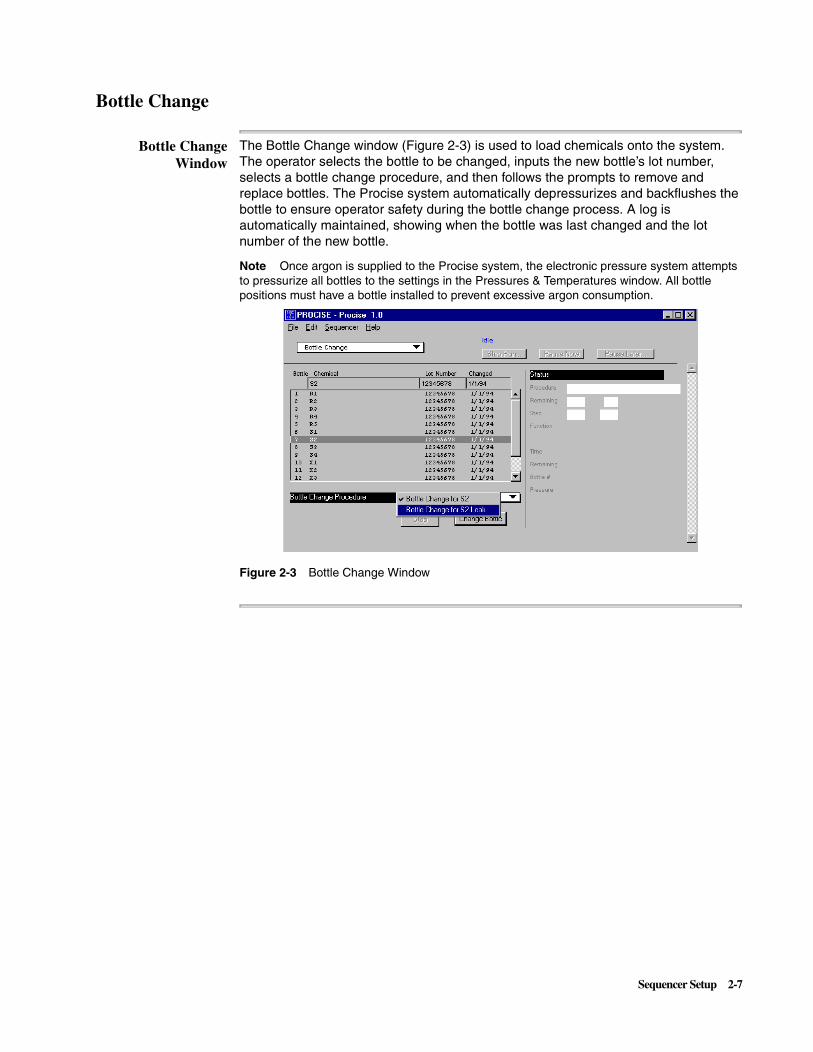
Bottle ChangeWindow
The Bottle Change window (Figure 2-3) is used to load chemicals onto the system. The operator selects the bottle to be changed, inputs the new bottle’s lot number, selects a bottle change procedure, and then follows the prompts to remove and replace bottles. The Procise system automatically depressurizes and backflushes the bottle to ensure operator safety during the bottle change process. A log is automatically maintained, showing when the bottle was last changed and the lot number of the new bottle.
Note Once argon is supplied to the Procise system, the electronic pressure system attempts to pressurize all bottles to the settings in the Pressures & Temperatures window. All bottle positions must have a bottle installed to prevent excessive argon consumption.
Figure 2-3 Bottle Change Window
Sequencer Setup 2-7

Changing a Bottle To change a bottle:
Step Action
1 IMPORTANT The Procise system must be idle or paused prior to changing a bottle. Select the pause function at the top of the window. Click Pause Now or Pause Later... to pause the cycle.
Select the Bottle Change window.
2 Select the bottle to be changed by clicking in the appropriate line in the reagent and solvent list. Enter the new lot number.
3 Choose the appropriate bottle change procedure in the Bottle Change Procedure window.
4 Click Change Bottle. A message appears when the bottle can be safely removed.
5 When prompted, remove the old bottle and bottle seal. Put a new bottle seal on the new bottle’s rim and screw the new bottle into the bottle cap assembly. Tighten until the bottle seal contacts the top of the bottle cap assembly and then turn approximately 1/4-turn more.
IMPORTANT It is not necessary to tighten a bottle until a snapping sound is produced by the bottle cap assembly. “Ratcheting” the bottle cap assembly causes premature wear and may crack the bottle receptacle.
6 Click Continue and the remaining steps in the bottle change procedure are executed.
Note You are prompted to select Save to save the chemical data you have changed or Revert to return to the previous entry.
7 If a run was paused, click the Resume button at the top of the Bottle Change window to continue the run.
2-8 Sequencer Setup

PTH-Amino Acid Standard
Overview A kit containing the PTH derivative of the 20 commonly occurring amino acids is provided with the Procise sequencer. The standard mixture is reconstituted to a user-specified concentration and loaded on the sequencer in the R5 position. The PTH-amino acid standard is required for peak identification and calibration of sequencer performance.
About R5 Note Be sure to use R5 acetonitrile reagent for all standard dilutions. This reagent contains a small amount of DTT (0.001%) which increases the stability of the PTH-amino acids. See “Chemical Warnings” on page 1-5.
Preparing StockSolutions
Preparing FreshWorking Solution
Preparing FreshDilution for Loading
To prepare stock solutions (1 nmol of each component/10 µL):
Step Action
1 Uncap each of the three vials. (If PTH-PE-Cys is not desired, it should be omitted from the standard.)
2 Add 1.0 mL of R5 reagent to each of the PTH standards.
3 Blanket the vials with inert gas.
4 Cap the vials and vortex thoroughly. Allow 20 minutes for the contents to dissolve, mixing several times during this period.
5 Store the stock solution vials at –20 °C.
To prepare fresh working solution (1 pmol of each of the PTH-amino acids/µL):
Step Action
1 Transfer 100 µL of each stock solution to a clean, dry 10-mL volumetric flask or graduated cylinder.
2 Bring to a total volume of 10 mL with R5 reagent.
3 Mix thoroughly. Transfer the dilution to a clean, dry sequencer reagent bottle.
4 Store the working solution at –20 °C.
To prepare fresh dilution for loading:
Step Action
1 Add the appropriate volume of the working solution to a clean, dry volumetric flask or graduated cylinder.
For a 10 pmol standard, add 2.5 mL.
For a 5 pmol standard, add 1.25 mL.
For a 2 pmol standard, add 0.5 mL.
2 Bring to a total volume of 10 mL with R5 reagent.
3 Mix thoroughly. Transfer the dilution to a clean, dry polyethylene standard bottle.
4 Use the Bottle Change procedure to load the new standard.
Sequencer Setup 2-9

Storing ChemicalSolutions
BioBrene Plus Solution
Overview BioBrene Plus reagent is a cationic polymer used to immobilize protein or peptide samples on the glass-fiber filter used for sequencing. BioBrene Plus reagent is a dehydrated compound that must be reconstituted using 750 µL of distilled water. This gives a final concentration of 1.5 mg polybrene and 0.1 mg NaCl per 15 µL. Use 15 µL of this stock solution on the filter disc for each application.
To store chemical solutions:
Step Action
1 Store the stock solutions at –20 °C for up to 6 months.
2 Store the working solution at –20 °C for up to 1 month.
3 On the system, the standard may be used for peak identification for up to 1 week. Several of the PTH-amino acids (PTH-Ser, PTH-Thr, PTH-Arg, and PTH-PE-Cys) are less stable in solution than the other PTH-AAs at room temperature. Accordingly, if accurate quantitation of these residues is desired, the standard should be changed more frequently.
2-10 Sequencer Setup

ß-lactoglobulin Solution
Overview ß-lactoglobulin is used as a standard for evaluating the sequencing efficiency of the Procise system. Solutions are prepared as described below. See “Chemical Warnings” on page 1-5.
Preparing DilutionSolvent
Preparing StockSolution
Preparing Dilutions
Storingß-lactoglobulin
To prepare dilution solvent:
Step Action
1 Aliquot 40 mL of S4B (20% acetonitrile/water, P/N 400314) into a clean 2-oz bottle.
2 Add 40 µL of R3 (trifluoroacetic acid, P/N 400003) to the bottle and mix well.
To prepare stock solution:
Step Action
1 Add 500 µL of dilution solvent to the vial.
2 Vortex and/or sonicate vial to dissolve the protein. This may require 20 minutes of intermittent mixing.
To prepare dilutions:
Step Action
1 Rinse a clean Eppendorf tube thoroughly with distilled water, and then dry it.
2 For 100 picomoles ß-lactoglobulin/20 µL (50 picomoles ß-lactoglobulin/10 µL), add 20 µL of the stock solution and 180 µL of the dilution solvent to the clean tube.
3 For 20 picomoles ß-lactoglobulin/20 µL (10 picomoles ß-lactoglobulin/10 µL), add 20 µL of the stock solution and 980 µL of the dilution solvent to the clean tube.
4 Mix thoroughly by gently vortexing the tube.
To store chemicals:
Step Action
1 Store the dilution solvent and dilutions at 4 °C or below.
2 Store the stock solution at –20 °C.
3 Discard the stock solution after 6 months.
4 Discard any dilutions of the stock solution after 1 month.
Sequencer Setup 2-11
Waste Bottle
Overview The waste bottle must be emptied when the liquid level rises to within 2 inches of the top of the bottle. Do not empty the waste bottle when the instrument is sequencing.
CHEMICAL WASTE HAZARD. Wastes produced by Applied Biosystems instruments are potentially hazardous, and can cause injury, illness, or death.
� Read and understand the material safety data sheets (MSDSs) provided by the manufacturers of the chemicals in the waste container before you store, handle or dispose of chemical waste.
� Handle chemical wastes in a fume hood.
� Minimize contact with and inhalation of chemical waste. Wear appropriate personal protective equipment when handling chemicals (e.g., safety glasses, gloves, or clothing).
� Seal the waste container with the cap provided after disposing of the contents.
� Dispose of the contents of the waste tray and waste bottle in accordance with good laboratory practices and applicable environmental and health regulations.
Emptying the WasteBottle
Besides collecting waste, the waste bottle assists venting by acting as a low pressure area. Chemical deliveries flow from high pressure (reagent or solvent bottle) to low pressure (vent or waste). Therefore, for flow to occur, the waste bottle and its associated delivery and exhaust lines must be open to the vent only. If the waste bottle is not effectively vented, gas and liquid deliveries will be impeded.
Emptying the TrapBottle
WARNING!
To empty the waste bottle:
Step Action
1 Raise the black bar above the waste bottle and carefully pull the waste bottle out of the waste container box. Immediately cover the bottle to contain the vapors.
2 Discard the waste.
3 Add about 1 inch of water to the waste bottle.
4 Raise the black bar, install the waste bottle, and release the bar.
5 Inspect the top of the bottle where it seals against the O-ring on the waste manifold. The entire seal should be inside the bottle. The O-ring should be flattened against the bottle surface. Rotating the bottle helps in properly seating the O-ring.
CAUTION!
To empty the trap bottle:
Step Action
1 There is a polypropylene trap bottle mounted on the rear of the sequencer. This bottle traps any condensate from the waste bottle vapor. When the sequencer is operated using N-methypiperidine as the coupling base, this condensate is acidic and collects very slowly. The trap bottle can be left empty or, if desired, place approximately 0.5 inch of sodium or potassium hydroxide pellets in the bottom of the bottle to neutralize the waste. Empty the trap bottle when it is 40–50% full. This is rarely required.
2-12 Sequencer Setup

3
HPLC Setup 3000 I'M INVISIBLE
Overview
About This Chapter This chapter describes the procedures for preparing solvents, changing solvents and columns, modifying the gradient, and optimizing the PTH-amino acid separation.
These procedures give the menu prompts and the operator responses to the menus. For complete descriptions of the menus used to control the pumps, refer to the Model 140C Microgradient Delivery System User’s Manual (P/N 903078). A general description of gradients and how gradient programming works is included. Instructions for optimizing the PTH-AA (Phenylthiohydantoin-amino acid) separation are on page 3-12.
In This Chapter This chapter contains the following topics:
Topic See Page
Preparing Solvents 3-2
Replacing Solvents 3-4
Changing the Column 3-6
Gradient Programming 3-8
Optimizing the PTH-Amino Acid Separation 3-12
HPLC Setup 3-1

Preparing Solvents
Overview Chemicals used with the Model 140C Microgradient Delivery System include two solvents (Solvent A3, 3.5% aqueous tetrahydrofuran, and Solvent B2, acetonitrile/isopropanol) and Premix Buffer Concentrate. Use these solvents and the buffer concentrates to prepare the HPLC mobile phases that elute the PTH-AAs from the analytical column. See “Chemical Warnings” on page 1-5.
Note Column temperature (55 oC) may vary slightly for optimum separation.
Note The column insert shipped with every column provides specific optimization guidelines.
Aged Mobile Phase If the system is not used for a week or more, prepare new Solvents A3 and B2 and optimize the separation before sequencing a protein or peptide. The following conditions may indicate aged mobile phase:
� A change of peak shape (i.e., broadening or tailing)
� An increase in baseline noise, or an unusual baseline rise
� A decrease in peak resolution that cannot be corrected by minor mobile phase component adjustments
� Precipitate in the mobile phase
Sufficient Quantities Note Before starting to sequence a sample, be sure there are sufficient quantities of Solvents A3 and B2 to complete the run. Changing mobile phase during sequencing can cause retention times to shift and make peak identification difficult.
Table 3-1 Typical Mobile Phase Composition (New Column)
Bottle Fluid Volume Part Number
Solvent A (approximately 100 analyses)
3.5% THF/H2O (Solvent A3)
1000 mL 401464
Premix Buffer Concentratea
a. The amount of Premix Buffer Concentrate added must be properly adjusted to achieve optimal separation of PTH-glutamic acid from DMPTU and both PTH-histidine and PTH-arginine from other PTH-amino acids.
25 mL 401446
1% Acetone 1 mL —
1 M NaH2PO4 or KH2PO4 100 µL —
Solvent B (approximately 150 analyses)
Acetonitrile/isopropanol (Solvent B2)
1000 mL 401570
3-2 HPLC Setup

Preparing the HPLCMobile Phase
To prepare the HPLC mobile phase:
Step Action
1 IMPORTANT Always use clean glassware for preparing Solvents A and B to minimize contaminants in the system.
Note If the PTH column is new, review the optimization information listed on the column insert on the line labeled Memo. If the current column was used at installation and the separation is optimal, use the conditions listed in the installation report.
Prepare 1 liter of Solvent A. Add 25 mL Premix Buffer Concentrate to the 1-L bottle of Solvent A3. Invert the bottle several times to mix the contents.
2 (Optional) Add up to 1 mL of HPLC-grade 1% acetone in H2O to 1 L of Solvent A3.
Note Adding acetone to Solvent A3 increases this solvent’s UV absorbance, thereby reducing the baseline rise observed with increasing concentrations of Solvent B2 during gradient elution.
3 Add 100 µL of 1 M NaH2PO4 or KH2PO4 (reagent grade) to 1 L of Solvent A3.
Note Adding sodium phosphate or potassium phosphate to Solvent A3 can help prevent the occurrence of a downward-sloping baseline associated with metal contamination of the HPLC pumps, column, or solvents.
4 Enter the following information in the Bottle Change window and the sequencer logbook: the date, the lot numbers of the solvents and buffer concentrate, and the amount of the buffer concentrate added to the solvents.
HPLC Setup 3-3

Replacing Solvents
Overview When installing new solvents, purge the separation system. A purge rapidly expels solvents and trapped gases from the pump syringes. Before sequencing or evaluating the separation, equilibrate the column with the new solvents until the baseline is stable. Use the procedure below to change the HPLC mobile phase. For additional information, refer to the Model 140C User’s Manual. Control the pump from the front panel keyboard of the Model 140C pump.
Changing Solvents To change solvents:
Step Action
1 Remove the old solvent bottle(s).
Comply with all applicable laws and regulations related to chemical storage, handling, and disposal.
2 Check the solvent lines for obstructions or salt deposits. If the lines are not clear, clean or replace them. Check all fittings for salt deposits or indications of leakage. Clean or replace as necessary.
3 Empty the pump cylinders and solvent inlet tubing. The Model 140C pump is equipped with an automatic purge valve to divert the flow of solvent to waste.
a. Purge the pumps and lines to remove all the old solvent. Press PURGE>. The screen changes to the Purge Pump screen.
b. Complete the screen as follows:
4 Place the solvent inlet line into the new bottle, attach the cap, and place the bottle in the bottle holder. Repeat for each new bottle.
Line Prompt Description Action
1 Purge rate?
Rate at which the cylinder empties. Maximum value is 10000, or 10 mL/min. The smaller the value entered, the longer the purge takes.
Enter a value between 7000 and 10,000 µL/min. Use the arrow keys to move the cursor through the selections.
2 Syringe? Syringe to purge: A, B, or Both
Select Both.
Number of purges?
Number of times to purge the pumps
Use the numeric keypad to enter 2.
3 Percent of syringe?
Percentage of the syringe to empty, refill, and empty again
Enter 100 with the numeric keypad. Then press BEGIN>.
4 Pump status
Appears while pumps are purging
If necessary to stop a purge, press Stop.
3-4 HPLC Setup

5 Purge the pumps and lines to rinse them with the new buffers. Purge the pumps twice at 100% to thoroughly rinse all the tubing and the pump heads with fresh Solvent A and B, and remove any bubbles in the system.
a. Press PURGE>.
b. Complete the screen as follows:
Note Before starting a run, always purge as described in step 5 to remove old solvent from the pump cylinders. The purge also clears any air bubbles that may have formed in the solvent supply lines while the instrument was idle.
6 Equilibrate the column with the new buffers.
a. Press Manual. The pumps fill with the new solvents and the screen changes to display the Pump Control menu.
b. Pump new solvent at 50 %B and 325 µL/min for approximately 5 minutes to allow the column to equilibrate with the new mobile phase(s). Use the softkeys to enter the flow rate (FLOW>, 325 µL/min), solvent composition (%B>, 50%) and the maximum operating pressure (PRESS>, 4000 psi). Press Enter after each selection. Use the arrow keys (← and →) to select Events O (open, off) or C (closed, on).
c. After replacing the buffers, always run several Flask Standard cycles to check that the PTH-AAs separate efficiently and reproducibly before sequencing an unknown sample. If the separation is essentially the same as with the old buffers, begin sequencing. If the separation changes significantly with the new buffers, then evaluate the separation and optimize it using the guidelines in “Optimizing the PTH-Amino Acid Separation” on page 3-12 . Always run at least four Flask Standard cycles and compare the last two before deciding that the separation needs to be optimized.
To change solvents: (continued)
Step Action
Line Prompt Description Action
1 Purge rate?
Rate at which the cylinder empties. Maximum value is 10000, or 10 mL/min. The smaller the value entered, the longer the purge takes.
Enter a value between 7000 and 10,000 µL/min that does not over-pressurize your system.
2 Syringe? Syringe to purge: A, B, or Both
Select Both.
Number of purges?
Number of times to purge the pumps, in this case, to thoroughly rinse the pump cylinders
Use the numeric keypad to enter 2.
3 Percent of syringe?
Percentage of the syringe to empty, refill, and empty again
Enter 100 with the numeric keypad. Then press BEGIN>.
4 Pump status
Appears while pumps are purging
If necessary to stop a purge, press Stop.
HPLC Setup 3-5

Changing the Column
Description The analytical column is a 22-cm long x 2.1-mm i.d. cartridge-style column packed with a reversed-phase support (5 micron, PTH-C18). The cartridge can be easily replaced when it no longer provides an acceptable separation of PTH-AAs.
The Procise system is equipped with a cartridge-type column for easy replacement. Columns are held in place by knurled end-seal assemblies (see Figure 3-1).
Figure 3-1 Column Holder Assembly
The knurled end-seal assemblies must be handtightened only. If they are overtightened, the seals will be damaged. The holder should be centered between the two knurled end-seal assemblies.
Do not scratch or dent the column ends while handling them during installation. Damage to the column ends may cause leaks which can be corrected only by replacing the column. Care must be taken when handling columns. Mishandling, such as dropping or bumping, can irreversibly damage the consistency of the packed bed and therefore impair the separation efficiency.
When toReplace a Column
If the chromatography shows consistently broad peaks, tailing peaks or poor separation which cannot be improved by adjusting Solvent A composition or preparing new Solvents A and B, change to a new column or to a known-good column. If the separation dramatically improves with the new column, discard the old column. It is no longer suitable for analysis.
Removing orReplacing a Column
Unscrew this endGRASP THIS END
AND HOLD STEADYUNSCREW THIS
END
KNURLED END SEAL
CARTRIDGE HOLDER
CARTRIDGE
OUTLET
OUTLET
INLET
INLET
Grasp this end and hold steadyUnscrew this end
Inlet
Inlet
Cartridge CartridgeHolder Seal
Knurled End
Outlet
Outlet
Cartridge
CAUTION!
CAUTION!
To remove or replace a column:
Step Action
1 If the pump is running, press Stop on the front panel of the Model 140C pump. If the column is to be reused, use the manual mode to flush the column with 90% Solvent B for 5 minutes at 300 µL/min before removing.
2 Lift and remove the upper heating block.
3 Unscrew and remove the knurled end seal assembly closest to the injector valve by rotating it counterclockwise.
4 Pull the cartridge column from the open holder. If the cartridge is to be used again, seal the ends with paraffin film.
3-6 HPLC Setup

5 Insert a new cartridge firmly in the holder. Position the label to show through the holder window, and screw the knurled end-seal assemblies to the holder hand-tight. Do not use tools to tighten the holder assembly.
6 In Manual mode, use the softkeys on the pump to enter the flow rate (FLOW>, 325 µL/min), solvent composition (%B>, 90%), and the maximum operating pressure (PRESS>, 4000 psi). Press Enter after each selection.
7 After a few minutes, check around the fittings for any obvious leaks. If leaks are found, carefully tighten the knurled end-seals and cartridge holder by hand. Do not use tools to tighten these components. Persistent leakage from the cartridge holder indicates damage either to the column or the knurled end-seal assemblies. Stop a leak at a fitting or bushing by tightening the fitting 1/4-turn with a small wrench (1/4 or 5/16 inch, according to the size of the fitting). Persistent leaking from a fitting indicates that the fitting has been damaged by overtightening and needs to be replaced.
8 Periodically check all column connections for leaks. Heating the column and holder may cause the fittings to expand and leak. Continue to run until a stable baseline is achieved.
9 Replace the column heater cover. Continue to run until a stable baseline is achieved.
10 Change the solvent composition to 50 %B and continue to flush the column for 15–30 minutes.
11 Equilibrate to the initial %B of your gradient. When there are no leaks and when the temperature, baseline, and operating pressure have stabilized, the instrument is ready for sequencing. To check the stability of the operating pressure, watch line 2 on the Manual Control menu. The pressure should vary no more than 10 psi. If the baseline drifts after 15 minutes of equilibration, continue delivering solvent until the baseline is steady. Optional: Monitor the baseline with the chart recorder.
12 Run a few Flask Standard cycles to check the stability of the separation on the new column before sequencing an unknown sample.
13 Document the column change by entering the change in the Bottle Change Log window on the Procise system.
To remove or replace a column: (continued)
Step Action
HPLC Setup 3-7

Gradient Programming
Overview Gradient programs change pump flow rates and composition on a time-programmed basis. A gradient program (gradient) consists of a series of steps. Each step has a time, a flow rate, and a flow composition (the output of the pumps in %B). Each step may also turn events on or off. The time listed for the step is the time after the gradient is started, either by injection of a sample or by activation of Function 232, Start Gradient. The composition (%B) and flow rate change as a linear function of time between steps.
Typical HPLCSettings
Table 3-2 lists the HPLC settings found in the Gradient View in the Screen Information column together with the typical values. The Description column explains what the entries mean and lists the range of accepted values as well as the default values.
Table 3-2 Typical HPLC Settings
Screen Information Description
Gradient: Fast Normal 1 The gradient Fast Normal 1 can be modified, or a new gradient can be created and stored under a unique name.
Max. pressure: 4000 psi Pressure above this value stops the pumps. Choices are 0 through 4000. The default value is 4000.
Min. pressure: 0 psi Pressure below this value stops the pumps. Typical values are 0 to 100 psi. The default value is 0.
Target pressure: 1000 psi The pressure the HPLC system should reach within the target time. Choices are 0 through 4000, but must be within the limits set by the maximum and minimum pressure above. The target pressue varies according to the flow rate, column length, and column packing. The default value is 1000 psi.
Target time: 1.0 min The amount of time the pumps use to reach target pressure. Choices are 0.0 to 99.9. Typical values are 0.1 to 1.0 minute. The default value is 1.0 minute.
Data collection time: 20 min The length of time for which data is collected by the Procise control software. Injection of the sample initiates data collection. The default value is 20 minutes.
3-8 HPLC Setup

Typical GradientProgram
Table 3-3 lists the steps of a typical gradient in the first four columns, and describes the flow rate and composition for each step in the last column.
Table 3-3 Typical Gradient Program
Time %B µL/min Event Description
0.0 6a
a. These %B values are suggested starting values and may need adjustment to resolve all amino acid peaks. See “Optimizing the PTH-Amino Acid Separation” on page 3-12 for examples showing how to adjust gradient and Solvent A composition to correct poor resolution of PTH-AAs.
325 1 2 The pumps start pumping 6 %B. Combined flow from pumps A and B is 325 µL/min. Turn on the chart recorder by selecting event 1. Autozero by selecting event 2.
0.3b
b. Time 0.1 minute cannot be used for gradient programming.
6 325 1 Autozero release by deselecting event 2.
0.4 16 325 1 A quick jump in %B from 0.3 to 0.4 minutes allows a lower starting %B without loss of resolution of peaks S through G. From time 0.4 to time 18.0, the pumps linearly increase the %B from 16 %B to 44 %B.
18.0 44a 325 1 Gives a start time for the pumps when they change the composition (%B). In the 0.5 minute between steps 3 and 4, the pumps linearly increase the %B from 44 %B to 90 %B. Combined flow from pumps A and B remains constant at 325 µL/min.
18.5 90 325 1 Flow and composition remain the same (90 %B and 325 µL/min) for 1.5 minutes. This segment of the program washes contaminants and byproducts of the Edman degradation from the column in preparation for the next sample.
20.0 90 325 0 Turn off the chart recorder by selecting the event 0.
21.5 90 325 0 The pumps stop at 21.5 minutes after the injection, unless another sequencer cycle tells the pumps to Prepare Pump.
HPLC Setup 3-9

Pump ControlFunctions
Two pump control functions are used with cycles:
� Function 227, Prepare Pump, stops the pump (if it is currently running), refills and pressurizes the syringes, and then runs the pump at the time-zero conditions defined in the gradient.
� Function 232, Start Gradient, can be used to start a gradient without an injection.
Prepare Pump downloads the gradient to the pump. Any changes made to the gradient on the Windows NT–based computer are not implemented until the next time Prepare Pump is selected.
When programming a cycle, Function 227, Prepare Pump, must occur at least 10 minutes before the sample is injected on the column. These 10 minutes allow for equilibration of the column at the time-zero conditions defined in the gradient. Inadequate equilibration results in variability in retention times and resolution.
%B To maintain constant %B during a program segment, set the %B to the same value for the two steps spanning that segment. To generate a gradient (i.e., change %B) during a segment, simply set different %B values for the two steps. Positive or negative changes in %B are generated depending on the relative %B values at the two steps.
Last Step The time of the last step entered in a program is the end-of-run time. At the last step in the program, the pump stops flow to the column. (This does not happen if the field Manual is set to Y on the Programs screen.) When the pump receives the Prepare Pump signal from the Procise system, the syringes refill for the next analysis, pressurize to the target conditions, and pump solvent at time-zero conditions.
Note At the last step in the program, the pump stops flow to the column. In the standard gradient (Fast Normal 1), the pump stops at 21.5 minutes after the injection, unless a subsequent sequencer cycle sends a Prepare Pump message.
ContinuingSolvent Flow
Once the sample is injected onto the analytical column, always continue the solvent flow until all of the sample components elute from the column and pass through the detector. Sample components remaining on the column may elute during a subsequent run and interfere with peak identification and quantitation.
ChangingFlow Rate
Change the flow rate by setting different flow-rate values for the two program steps spanning a program segment. Enter a %B value for every step. If no new flow-rate value is entered for a step, the value for the previous step is held throughout the segment spanning two steps.
External Events In addition to changing %B or flow rate during a program, the gradient program can control external events. These events include integrator start, autozero detector, chart recorder start/stop, additional A/D start/stop, or additional data collection start/stop. Data collection by SequencePro software is started automatically by sample injection. Control of external events is accomplished through relay closures (events 1 through 4) on the terminal strip located on the Procise rear panel. These relay closures are controlled by selecting 1, 2, 3, and/or 4 in the Event Column. The events remain in effect until canceled by removing the appropriate number(s) from the Event Column (or by the “end of run” signal, which sets all external events to Off).
3-10 HPLC Setup

Time Limit Because the pump syringes have a limited volume, there is a limit to the time between the Prepare Pump and Load Injector steps. This time limit depends upon the time-zero flow rate and %B conditions, and the volume of solvents required during the pressurization and analysis cycles. The pump begins beeping when 5 minutes of equilibration time is left before injection. If the limit is exceeded, the pump continues pumping until one of the syringes empties or until the start signal arrives. If the start signal is received late (because of a hold or pause in the sequencer cycle), there may not be enough buffer in the syringes to complete the analysis. When the syringes empty, the analysis terminates, and the syringes refill in preparation for the next run before elution is complete. Sample components remaining on the column may elute during a subsequent cycle and interfere with peak identification and quantitation.
HPLC Setup 3-11

Optimizing the PTH-Amino Acid Separation
AdjustmentOverview
For certain PTH-amino acids, optimal position can be achieved or restored by adjusting the molarity or pH of Solvent A, the %B, or the column oven temperature. Figure 3-2 and Figure 3-3 summarize adjustments that can be made to improve the relative positions of certain amino acids.
Figure 3-2 Separation Guidelines for the Original Solvent System
Figure 3-3 Separation Guidelines for the Premix Solvent System
pH
DTT
pH
Fina l% B
OvenTemp
DMPTU
Molar i t y
DPTU
DPU
Fina l % B
RenewSolvent A
Separat ion Guide l inesFor the Or ig ina l So lvent Sys tem
D N S Q T G E A H Y R P M V C W F I K LDecrease
Increase
In i t ia l % B
pH
Molar i t y
Molar i t y
In i t ia l% B
pH
Molar i t y
Molar i t y
Molar i t yOven Temp by 2 C
DTT
In i t ia l % B
Fina l% B
DMPTU
Premix
DPTUDPU
Fina l % B
RenewSolvent A
Separat ion Guide l inesFor the Premix So lvent Sys tem
D N S Q T G E H A R Y P M V C W F I K LDecrease
Increase
In i t ia l% B
In i t ia l % B
Premix
Premix
In i t ia l% B
Premix
Premix
Premix
In i t ia l% B
In i t ia l% B
In i t ia l% B
In i t ia l % B
Decrease Co lumn Temp
by 2 C
3-12 HPLC Setup

Separation ofStandards
Figure 3-4 is a typical separation of 10 pmol of PTH-amino acid standards with Premix solvent system and Solvent B2 on the Procise system.
Figure 3-4 Typical Separation of Standards
D N
S
Q
T
G
E
DMPTU
H
A
R
Y
PE-C
P
MV
DPTU
W
DPU
F
I
K
L
+ 1.00
0.00
- 1.00
- 2.00
3.0 6.0 9.0 12.0 15.0 18.0
2: Standard 1
DTT
HPLC Setup 3-13


4
Sequencer Operation 4000 I'M INVISIBLE
Overview
About This Chapter This section describes the common procedures needed for day-to-day operation of the Procise® Protein Sequencing System. You are instructed on how to precycle a glass filter with BioBreneTM Plus Reagent, load samples on cartridges, set up the run using the Procise control software, and monitor the run using SequencePro software.
In This Chapter This chapter contains the following topics:
Topic See Page
Standard Sequencing Methods 4-2
Loading Reaction Cartridges 4-5
Starting a Run 4-9
Data Collection 4-11
Sequencer Idle Time 4-13
Sequencer Operation 4-1

Standard Sequencing Methods
Overview Ten standard sequencing methods are available in the Procise control software. For liquid-sample sequencing, you must use the Filter Precycle method for the Biobrene Plus-solution-treated filter prior to sample loading, followed by either Pulsed-Liquid or Gas-Phase method sequencing. For blotted/membrane-bound samples, choose either a pulsed-liquid method (PL PVDF) or a gas-phase method (GP PVDF). The standard methods are listed in Table 4-1.
Table 4-1 Standard Methods
Method Name Run Order Cartridge Flask Gradient
Filter Precycle Default Cart Pulsed-liquid
Flask Normal Fast Normal 1
1 None Flask Prep Cycle
Prep Pump
2 Cart Precycle Flask Blank Fast Normal 1
3 Cart Precycle Flask Standard Fast Normal 1
— Starting Temp (°C)
48 64 55
Fast Precycle Default Cart Precycle None None
1 Cart Precycle Flask Standard Fast Normal 1
— Starting Temp (°C)
48 64 55
Pulsed-Liquid Default Cart Pulsed-liquid
Flask Normal Fast Normal 1
1 None Flask Prep Pump
Fast Normal 1
2 None Flask Blank Fast Normal 1
3 Cart Begin Flask Standard Fast Normal 1
— Starting Temp (°C)
45 64 55
Gas-Phase Default Cart Gas-Phase
Flask Normal Fast Normal 1
1 None Flask Prep Pump
Prep Pump
2 None Flask Blank Fast Normal 1
3 Cart Begin Gas-Phase
Flask Standard Fast Normal 1
— Starting Temp (°C)
45 64 55
4-2 Sequencer Operation

PL PVDF Protein
Default Cart PL PVDF Protein
Flask Normal Fast Normal 1
1 None Flask Prep Pump
Prep Pump
2 None Flask Blank Fast Normal 1
3 Cart Begin Flask Standard Fast Normal 1
— Starting Temp (°C)
48 64 55
GP PVDF Protein
Default Cart GP PVDF Protein
Flask Normal Fast Normal 1
1 None Flask Prep Pump
Prep Pump
2 None Flask Blank Fast Normal 1
3 Cart Begin Gas-phase
Flask Standard Fast Normal 1
— Starting Temp (°C)
48 64 55
PL PVDF Peptide
Default Cart PL PVDF Peptide
Flask Normal Fast Normal 1
1 None Flask Prep Pump
Prep Pump
2 None Flask Blank Fast Normal 1
3 Cart Begin Flask Standard Fast Normal 1
— Starting Temp (°C)
48 64 55
GP PVDF Peptide
Default Cart GP PVDF Peptide
Flask Normal Fast Normal 1
1 None Flask Prep Pump
Prep Pump
2 None Flask Blank Fast Normal 1
3 Cart Begin Gas-phase
Flask Standard Fast Normal 1
— Starting Temp (°C)
48 64 55
Run Gradient Default None Run Gradient Fast Normal 1
— Starting Temp (°C)
35 64 55
PTH-Standards Default None Flask Standard Fast Normal 1
— Starting Temp (°C)
35 64 55
Table 4-1 Standard Methods (continued)
Method Name Run Order Cartridge Flask Gradient
Sequencer Operation 4-3

Filter Precycle When sequencing a liquid sample, you must load the glass-fiber filter with BioBrene Plus solution (a cationic polymer used to immobilize the sample on the filter during Edman chemistry) and run the Filter Precycle method before loading the sample. The Filter Precycle is necessary because BioBrene Plus solution may contain small amounts of compounds that could interfere with sequencing. Filter precycling washes and conditions the BioBrene Plus-solution-coated filter by running several short cycles of the Edman chemistry.
Two methods are available for filter precycling.
� The Filter Precycle method includes two filter-conditioning cycles and a sequencing cycle allowing evaluation of the chemical and amino acid background level prior to sample loading. This method requires at least 2.5 hours for completion.
� The Fast Precycle method includes two filter-conditioning cycles but does not include a sequencing cycle. This method requires approximately 1 hour for completion but does not allowing evaluation of the chemical and amino acid background level prior to sample loading.
Sequencing LiquidSamples
Two methods are available for sequencing liquid samples.
� The Pulsed-Liquid method delivers a small aliquot of liquid TFA to the cartridge for cleavage after coupling. This method has a cycle time of 34 minutes and offers slightly higher repetitive yields.
� The Gas-Phase method delivers TFA vapor for the cleavage and has a cycle time of 41 minutes. The Gas-Phase method offers lower background and reduced washout of hydrophobic samples, especially peptides.
SequencingBlotted/Membrane-
Bound Samples
Four methods are available for sequencing samples on PVDF membrane. Two of the four methods are for sequencing protein samples and include a delivery of 50% methanol from the X1 bottle during each coupling cycle. This improves the coupling efficiency for membrane-bound protein samples. These methods should not be used for peptide samples because the 50% methanol addition increases washout of the peptide. For peptide samples, a small amount (3–6 µL) of diluted Biobrene Plus solution (1 part 0.1% TFA, 2 parts methanol, 1 part Biobrene Plus solution) should be applied to the sample before sequencing.
� The PL PVDF Protein method delivers a small aliquot of 50% methanol to the cartridge during coupling and a small aliquot of liquid TFA to the cartridge for cleavage. This method has a cycle time of 36 minutes.
� The GP PVDF Protein method delivers a small aliquot of 50% methanol to the cartridge during coupling and TFA vapor to the cartridge for cleavage. This method has a cycle time of 43 minutes.
� The PL PVDF Peptide method delivers a small aliquot of liquid TFA to the cartridge for cleavage. This method has a cycle time of 34 minutes.
� The GP PVDF Peptide method delivers TFA vapor to the cartridge for cleavage. This method has a cycle time of 41 minutes.
4-4 Sequencer Operation

Loading Reaction Cartridges
Overview This section describes how to load samples onto cartridge(s). You choose the proper loading methods depending on the sample type. Liquid samples require a precycled BioBrene Plus-solution-treated glass fiber filter. Samples applied to the PVDF membrane by electroblotting, the ProSorb device, or the Model 173 MicroBlotter are placed in the cartridge with only a Zitex seal.
LoadingBioBrene Solution
HOT. Some components on the Procise sequencer may be hot! Use caution when working near hot components to avoid injury.
To precycle the BioBrene Plus-solution-treated filter:
Step Action
1 Remove the glass cartridge block holder(s):
a. Unscrew and remove the cartridge assembly cap.
b. Lift the glass cartridge block holder(s) from the cartridge assembly(s).
2 Remove the glass cartridge blocks:
a. Unscrew and remove the cartridge block holder cap.
b. Invert the holder body slowly to allow the cartridge blocks to slide out.
3 Clean the cartridge blocks:
a. Discard the used Zitex cartridge seal and glass-fiber filter.
b. Rinse the inner surfaces of both glass cartridge blocks with methanol.
c. Dry the cartridge blocks with a stream of argon in the cartridge drying assembly.
Note Always handle cartridge seals and glass-fiber filters with forceps.
4 Replace the lower glass cartridge block:
a. Put the lower glass cartridge block in the holder.
b. Place a new cartridge seal on top of the lower glass cartridge block.
5 Fit a new filter into the upper cartridge block:
a. Center the filter in the cartridge recess.
b. Press the filter gently in place with the tamper tool.
Note An off-center filter may cause cartridge sealing problems. Any rips or holes in the filter reduce sequencing efficiency.
6 After preparing the solution according to the amount desired for your particular sequencing sample, load the BioBrene Plus solution onto the center of the filter. The typical loading amount is 15 µL.
Note Be sure that the volume of BioBrene Plus solution applied to the filter is sufficient to wet the entire filter. Maximum liquid capacity of a dry filter is approximately 15 µL. Additional fluid can be loaded if the filter is allowed to dry between loadings.
7 Dry the filter:
a. Place the upper cartridge block in the cartridge drying assembly with the filter facing upwards.
b. Lower the sample drying arm.
c. Dry the filter for 5 minutes. After 5 minutes, the gas delivery is turned off. For additional drying, raise and lower the drying arm again.
WARNING!
Sequencer Operation 4-5

Loading Samples
8 Reassemble the glass cartridge blocks:
a. Insert the upper cartridge block in the holder so that the filter side faces down toward the lower block and Zitex seal.
b. Tighten the top of the cartridge block holder cap on the holder body.
9 Reassemble the cartridge assembly.
a. Insert the completed glass cartridge block holder, cap side up, in the cartridge assembly.
b. Place the cap on top of the assembly, align the guide pins and slots, then press down and turn the cap until it stops against the body of the assembly.
IMPORTANT The seal between the cartridge blocks and the Kel-F ferrules is made by spring force. Overtightening the cartridge assembly cap does not increase the sealing force.
To precycle the BioBrene Plus-solution-treated filter: (continued)
Step Action
To load samples:
Step Action
1 Remove the glass cartridge block holder(s):
a. Unscrew and remove the cartridge assembly cap.
b. Lift the glass cartridge block holder(s) from the cartridge assembly(s).
2 Remove the glass cartridge blocks:
a. Unscrew and remove the cartridge block holder cap.
b. Invert the holder body slowly to allow the cartridge blocks to slide out.
c. Place the upper cartridge block, precycled filter side up, on a clean, dry surface.
d. Discard the used cartridge seal.
3
4 For liquid samples, load the sample solution onto the center of the filter so that it is distributed evenly across the filter.
Note Maximum liquid capacity of a dry filter is approximately 15 µL. With very dilute samples, it may be necessary to load more than 15 µL total volume. Additional fluid can be loaded if the filter is dried between loading.
5 For liquid samples, dry the filter:
a. Place the upper cartridge block in the sample drying station with the filter facing upwards.
b. Lower the sample drying arm.
c. Dry the filter for 5 minutes. After 5 minutes, the gas delivery is turned off. For additional drying, raise and lower the drying arm again.
6 Reassemble the lower glass cartridge block:
a. Put the lower glass cartridge block in the holder.
b. Place a new cartridge seal on top of the lower glass cartridge block.
If samples are... Then...
Liquid Proceed to step 4.
Blotted/membrane-bound Place membrane piece(s) in the reaction chamber in the upper cartridge block. Then skip to step 6.
4-6 Sequencer Operation

Leak Testing theReaction Cartridges
Prior to starting a run, a cartridge leak test should be performed to verify that the cartridge assembly is leak tight. The cartridge leak test pressurizes the cartridge assembly at 3.8 psi and monitors the pressure drop for 30 seconds. The result of the test is reported in the Event Log file at the end of the test.
IMPORTANT User intervention commands (such as Jump, Pause, etc.) should never be used during leak procedures. Interrupting the procedure may invalidate the test results or prevent the pressure regulator from resetting to the correct pressure.
Note The leak tests can only be performed while the sequencer is idle.
Testing
If a cartridge fails the leak test, troubleshoot the cartridge.
Troubleshooting
7 Reassemble the upper glass cartridge block:
a. Insert the upper cartridge block in the holder so that the filter side faces down toward the lower block cartridge.
Note The easiest way to do this is by inverting the holder-lower-block-seal group over the upper block until full contact is made with the seal.
b. Tighten the cartridge block holder cap on the holder body.
8 Reassemble the cartridge assembly:
a. Insert the completed block holder in the cartridge assembly.
b. Place the cap on top of the assembly, align the guide pins and slots, then press down and turn the cap until it stops against the body of the assembly.
Note The seal between the cartridge blocks and the Kel-F ferrules is made by spring force. Overtightening the cartridge assembly does not increase the sealing force.
To load samples: (continued)
Step Action
To test for cartridge leaks:
Step Action
1 Select the Test view from the View menu.
2 Select the Leak option. Select the cartridge leak test to be used. Hold down the Ctrl key to select more than one test. Click the Start Test button.
To troubleshoot the cartridge:
Step Action
1 Remove the cartridge assembly cap.
2 Disassemble the cartridge block holder and check that the glass fiber filter is properly installed in the recess of the upper cartridge block.
3 Check the cartridge seal for tears or unevenness in the sealing impression.
4 Using a new seal, reassemble the cartridge block holder.
5 Check the Kel-F ferrules of the cartridge assembly cap for damage or foreign materials.
Sequencer Operation 4-7

Heating and Testing
If a cartridge still fails the leak test, you can try turning on the cartridge heater. Expansion due to heat sometimes makes the seal leak-tight.
To heat the cartridge and test for leaks:
Step Action
1 Turn on the cartridge heater and allow it to reach the setpoint.
2 Select the Test view from the View menu.
3 Select the Leak option. Select the cartridge leak test to be used. Hold down the Ctrl key to select more than one test. Click the Start Test button.
4-8 Sequencer Operation

Starting a Run
Procedure CHEMICAL WASTE HAZARD. Wastes produced by Applied Biosystems instruments are potentially hazardous, and can cause injury, illness, or death.
� Read and understand the material safety data sheets (MSDSs) provided by the manufacturers of the chemicals in the waste container before you store, handle or dispose of chemical waste.
� Handle chemical wastes in a fume hood.
� Minimize contact with and inhalation of chemical waste. Wear appropriate personal protective equipment when handling chemicals (e.g., safety glasses, gloves, or clothing).
� Seal the waste container with the cap provided after disposing of the contents.
� Dispose of the contents of the waste tray and waste bottle in accordance with good laboratory practices and applicable environmental and health regulations.
� Seal the waste container with the cap provided after disposing of the contents.
To start a run:
Step Action
1 Perform the Start-run checklist:
a. Check that the quantities of the sequencing chemicals and HPLC solvents are sufficient for the entire run. Replace chemicals as necessary. See “Bottle Change” on page 2-7.
b. Check the sequencer and HPLC waste levels. The sequencer waste bottle must be emptied when the liquid level rises to within 2 inches of the bottle top. Do not empty the waste bottle when the sequencer is running.
c. Check that the argon tank has enough gas for the entire run.
WARNING!
Sequencer Operation 4-9

2 Enter the sample and method information:
a. Select Start Run view from the View menu.
b. Select the cartridge run order. Cartridges can be run in any order. Selecting the run order for a cartridge activates the File Name, Cycles, and Methods fields.
c. Enter a unique file name for each sample.
d. Enter the number of cycles to be run by highlighting each Cycles field and typing the number, or by using the scroll up/down keys. For filter precycling, enter 4. When sequencing samples using the standard methods, please note that the first three cycles are Prepare Pump, a blank, and a standard. Therefore, if 20 residues of sequencing are required, enter 23 in the Cycles field.
e. Move the cursor to the Method drop down menu in the lower half of the window. Select the appropriate method for each cartridge.
f. Choose the sequencer startup procedure if the sequencer has been idle for more than one week prior to the current run.
g. Be sure the Collect Data box(es) are checked. Type the sample and standard amounts.
h. Click the Start Run button or press the Return key. Sequencing parameters are downloaded to the sequencer and the Monitor Run window is displayed.
To start a run: (continued)
Step Action
4-10 Sequencer Operation

Data Collection
Overview Figure 4-1 provides a graphic representation of data collection on the Procise system.
Figure 4-1 Virtual A/D Data Collection
A/D Converter There is an analog-to-digital (A/D) converter contained within the Procise protein sequencer. This A/D converter is similar to previous A/D converters from Applied Biosystems and is capable of storing a maximum of 90 minutes of data in its data buffer.
Procise ControlSoftware
The Procise control software is responsible for controlling the Procise sequencer and collecting the data from the sequencer’s internal A/D converter. Unlike previous sequencers, there is a high level of communication between the protein sequencer and the control software. If the Procise sequencer determines that the control software is not collecting the data from the internal A/D converter because the Windows NT–based computer has malfunctioned, the sequencer is paused automatically at the end of the current cycle until the control software resumes data collection. This provides a very robust mechanism for preventing data loss due to overwriting the A/D converter’s data buffer.
ProciseProtein
Sequencer
File I/O
Analog Signal HPLCDetector
Maximum ofone hour of data
Macintosh
Virtual A/D File
A/D StateHeader Information
Cycle 1 DataCycle 2 Data
•••
Cycle X Data
610AData
AnalysisSoftware
Procise/610Data File
610A Data Analysis Software Reads Data from Virtual A/D File
Procise Control Software Appends New Data to Virtual A/D File
InternalA/D Converter
RS232(Modem Port)
File I/O
When the A/D State is set tofinished and all data has beencollected but the Procise DataAnalysis software, the Virtual A/D file is deleted by the 610A software
ProciseControl
Software
File I/O
Computer
SequenceProSoftware
Procise/SequenceProData File
When the A/D State is set to finished and all data has been collected by the Procise Data Analysis software, the Virtual A/D file is deleted by SequencePro software
SequencePro Software Reads Data from Virtual A/D File
Maximum of 90minutes of data
Procise Control Software Appends New Data to Virtual A/D File
Sequencer Operation 4-11

Virtual A/D File When you start a sequencing run for a selected cartridge using the Procise control software, a virtual A/D file is created in the Procise folder. The initial version of the Virtual A/D file contains complete information on the Sequencer name and model, the sample name, the run date and time, the sample and standard amounts, and any other relevant information. As the control software collects the data from the internal A/D converter, the data is appended to any existing data in the Virtual A/D file. When the Procise sequencer notifies the control software that the run is complete, the control software sets the “run finished” flag in the Virtual A/D file to indicate that the file contains a complete set of sequencing data. At the end of the sequencing run, the Virtual A/D file contains the completed header information about the contents of the file, as well as the raw data for the cartridge and sample during each cycle in the sequencing run.
4-12 Sequencer Operation

Sequencer Idle Time
Overview When the sequencer is not used, oxygen diffuses slowly into the system, causing solvents and reagents to decompose and form byproducts which interfere with sequencing efficiency. To minimize sequencing problems due to chemical decomposition during an inactive period, use the procedures recommended in the following pages.
Idle Less ThanOne Week
No special considerations are necessary if the sequencer has been idle for less than 1 week. Before resuming sequencing after a short idle period, run the Startup procedure to replace all reagents in the lines with fresh reagents from the bottles. Purge the HPLC pump.
Idle One ToTwo Weeks
If the sequencer is to remain idle for 1 to 2 weeks, use the Idle procedure to flush all the reagent bottles intermittently.
The argon supply must remain connected to the sequencer in order for the Idle procedure to run. The Model 140C Microgradient Delivery System should be put in Manual mode (5–10 µL/min, 90 %B) for free run or cleaned out and shut down. Refer to the Model 140C User’s Manual for additional information.
The computer can be shut down after you execute the Idle procedure and after all the information is downloaded to the sequencer.
Idle 14–28 Days(Extended
Shutdown)
If the sequencer is to remain idle for 14–28 days and is to remain connected to argon and electrical supplies with the instrument power on, use the following procedure:
To initiate idling:
Step Action
1 From the Sequencer menu select Preferences...
2 Click on the Execute Idle procedure check box and type a value for how often the procedure should be run, ranging from once every hour to once every 999 hours. Run the Standard Idle procedure once every 8 hours. Select the Idle procedure from the menu and click OK.
To initiate idling:
Step Action
1 From the Test view in the Procise software, select and run the Short-Term Shutdown procedure to wash and flush all the valve blocks and backflush the reagents and solvents into the bottles.
2 Empty, rinse, and replace the waste bottle. See “Waste Bottle” on page 2-12
3 Put the Model 140C system into Manual mode, and run at 5–10 µL/min, 90 %B.
Sequencer Operation 4-13

Idle >28 Days(Extended
Shutdown)
If the sequencer is to remain idle for more than 28 days and is to be disconnected from argon and electrical supplies, use the following procedure:
Restarting AfterExtended Shutdown
To initiate idling:
Step Action
1 Replace the Model 140C Solvent A with HPLC-grade or deionized, distilled water. Purge both pumps three times at 100%. Run in Manual mode at 325 µL/min, 90 %B for at least 30 minutes.
2 Remove all solvent and reagent bottles from the sequencer.
3 Place a bottle of HPLC-grade methanol in the X3 bottle position. Place empty bottles on all other bottle positions.
4 From the Test view in the Procise software, select and run the Long-Term Shutdown procedure. The sequencer washes all the valve blocks and reagent- and solvent-delivery lines with methanol and flushes all lines and valve blocks with argon.
5 Empty, rinse, and replace the waste bottle.
6 Prepare the Model 140C system for shutdown.
a. Place both Model 140C solvent lines into a bottle of HPLC-grade or deionized, distilled water. Purge both pumps three times at 100%.
b. Place both Model 140C solvent lines into a bottle of Solvent B2. Purge both pumps three times at 100%.
c. Place both Model 140C solvent lines into clean, dry bottles. Purge both pumps three times at 100%.
7 Turn the instrument power off.
If the reagent and solvent bottles are not removed before an extended instrument shutdown, damage to the valve blocks may result.
CAUTION!
To restart the sequencer after an extended shutdown:
Step Action
1 Turn the sequencer power and the argon supply on.
2 Load fresh reagents and solvents. See “Sequencer Reagents and Solvents” on page 2-6.
3 Run the Startup procedure. See “Starting a Run” on page 4-9.
4 Prepare new HPLC solvents and purge the pump.
5 Run a blank gradient on the HPLC and check for leaks.
4-14 Sequencer Operation

A
Getting Help AOverview
About ThisAppendix
This appendix describes how to get technical help from Applied Biosystems.
Getting Help A-1

Technical Support
ContactingTechnical Support
You can contact Applied Biosystems for technical support by telephone or fax, by e-mail, or through the Internet. You can order Applied Biosystems user documents, MSDSs, certificates of analysis, and other related documents 24 hours a day. In addition, you can download documents in PDF format from the Applied Biosystems Web site (please see the section “To Obtain Documents on Demand” following the telephone information below).
To Contact TechnicalSupport by E-Mail
Contact technical support by e-mail for help in the following product areas:
Hours for TelephoneTechnical Support
In the United States and Canada, technical support is available at the following times:
To Contact TechnicalSupport by
Telephone or Fax
In North America
To contact Applied Biosystems Technical Support, use the telephone or fax numbers given below. (To open a service call for other support needs, or in case of an emergency, dial 1-800-831-6844 and press 1.)
Product Area E-mail address
Genetic Analysis (DNA Sequencing) [email protected]
Sequence Detection Systems and PCR [email protected]
Protein Sequencing, Peptide and DNA Synthesis
Biochromatography, PerSeptive DNA, PNA and Peptide Synthesis systems, CytoFluor®, FMAT™, Voyager™, and Mariner™ Mass Spectrometers
LC/MS(Applied Biosystems/MDS Sciex)
[email protected]@sciex.com
Chemiluminescence (Tropix) [email protected]
Product Hours
Chemiluminescence 8:30 a.m. to 5:30 p.m. Eastern Time
Framingham support 8:00 a.m. to 6:00 p.m. Eastern Time
All Other Products 5:30 a.m. to 5:00 p.m. Pacific Time
Product orProduct Area
TelephoneDial...
FaxDial...
ABI PRISM® 3700 DNA Analyzer 1-800-831-6844,then press 8
1-650-638-5981
DNA Synthesis 1-800-831-6844,then press 21
1-650-638-5981
Fluorescent DNA Sequencing 1-800-831-6844,then press 22
1-650-638-5981
Fluorescent Fragment Analysis (includes GeneScan® applications)
1-800-831-6844,then press 23
1-650-638-5981
A-2 Getting Help

Outside North America
Integrated Thermal Cyclers (ABI PRISM®
877 and Catalyst 800 instruments)1-800-831-6844,then press 24
1-650-638-5981
ABI PRISM® 3100 Genetic Analyzer 1-800-831-6844,then press 26
1-650-638-5981
BioInformatics (includes BioLIMS, BioMerge™, and SQL GT™ applications)
1-800-831-6844,then press 25
1-505-982-7690
Peptide Synthesis (433 and 43X Systems)
1-800-831-6844,then press 31
1-650-638-5981
Protein Sequencing (Procise Protein Sequencing Systems)
1-800-831-6844,then press 32
1-650-638-5981
PCR and Sequence Detection 1-800-762-4001,then press 1 for PCR,2 for the 7700 or 5700,6 for the 6700or dial 1-800-831-6844, then press 5
1-240-453-4613
Voyager MALDI-TOF Biospectrometry and Mariner ESI-TOF Mass Spectrometry Workstations
1-800-899-5858,then press 13
1-508-383-7855
Biochromatography (BioCAD Workstations and Poros Perfusion Chromatography Products)
1-800-899-5858,then press 14
1-508-383-7855
Expedite Nucleic acid Synthesis Systems
1-800-899-5858,then press 15
1-508-383-7855
Peptide Synthesis (Pioneer and 9050 Plus Peptide Synthesizers)
1-800-899-5858,then press 15
1-508-383-7855
PNA Custom and Synthesis 1-800-899-5858,then press 15
1-508-383-7855
FMAT 8100 HTS System and Cytofluor 4000 Fluorescence Plate Reader
1-800-899-5858,then press 16
1-508-383-7855
Chemiluminescence (Tropix) 1-800-542-2369 (U.S. only),or 1-781-271-0045
1-781-275-8581
Applied Biosystems/MDS Sciex 1-800-952-4716 1-650-638-6223
RegionTelephoneDial...
FaxDial...
Africa and the Middle East
Africa (English Speaking) and West Asia (Fairlands, South Africa)
27 11 478 0411 27 11 478 0349
South Africa (Johannesburg) 27 11 478 0411 27 11 478 0349
Middle Eastern Countries and North Africa (Monza, Italia)
39 (0)39 8389 481 39 (0)39 8389 493
Product orProduct Area
TelephoneDial...
FaxDial...
Getting Help A-3

Eastern Asia, China, Oceania
Australia (Scoresby, Victoria) 61 3 9730 8600 61 3 9730 8799
China (Beijing) 86 10 64106608 86 10 64106617
Hong Kong 852 2756 6928 852 2756 6968
Korea (Seoul) 82 2 593 6470/6471 82 2 593 6472
Malaysia (Petaling Jaya) 60 3 758 8268 60 3 754 9043
Singapore 65 896 2168 65 896 2147
Taiwan (Taipei Hsien) 886 2 22358 2838 886 2 2358 2839
Thailand (Bangkok) 66 2 719 6405 66 2 319 9788
Europe
Austria (Wien) 43 (0)1 867 35 75 0 43 (0)1 867 35 75 11
Belgium 32 (0)2 712 5555 32 (0)2 712 5516
Czech Republic and Slovakia (Praha) 420 2 61 222 164 420 2 61 222 168
Denmark (Naerum) 45 45 58 60 00 45 45 58 60 01
Finland (Espoo) 358 (0)9 251 24 250 358 (0)9 251 24 243
France (Paris) 33 (0)1 69 59 85 85 33 (0)1 69 59 85 00
Germany (Weiterstadt) 49 (0) 6150 101 0 49 (0) 6150 101 101
Hungary (Budapest) 36 (0)1 270 8398 36 (0)1 270 8288
Italy (Milano) 39 (0)39 83891 39 (0)39 838 9492
Norway (Oslo) 47 23 12 06 05 47 23 12 05 75
Poland, Lithuania, Latvia, and Estonia (Warszawa)
48 (22) 866 40 10 48 (22) 866 40 20
Portugal (Lisboa) 351 (0)22 605 33 14 351 (0)22 605 33 15
Russia (Moskva) 7 095 935 8888 7 095 564 8787
South East Europe (Zagreb, Croatia) 385 1 34 91 927 385 1 34 91 840
Spain (Tres Cantos) 34 (0)91 806 1210 34 (0)91 806 1206
Sweden (Stockholm) 46 (0)8 619 4400 46 (0)8 619 4401
Switzerland (Rotkreuz) 41 (0)41 799 7777 41 (0)41 790 0676
The Netherlands (Nieuwerkerk a/d IJssel)
31 (0)180 331400 31 (0)180 331409
United Kingdom (Warrington, Cheshire) 44 (0)1925 825650 44 (0)1925 282502
All other countries not listed(Warrington, UK)
44 (0)1925 282481 44 (0)1925 282509
Japan
Japan (Hacchobori, Chuo-Ku, Tokyo) 81 3 5566 6230 81 3 5566 6507
Latin America
Del.A. Obregon, Mexico 305-670-4350 305-670-4349
RegionTelephoneDial...
FaxDial...
A-4 Getting Help

To Reach TechnicalSupport Through
the Internet
We strongly encourage you to visit our Web site for answers to frequently asked questions and for more information about our products. You can also order technical documents or an index of available documents and have them faxed or e-mailed to you through our site. The Applied Biosystems Web site address is
http://www.appliedbiosystems.com/techsupp
To ObtainDocuments on
Demand
Free, 24-hour access to Applied Biosystems technical documents, including MSDSs, is available by fax or e-mail or by download from our Web site.
To submit technical questions from North America or Europe:
Step Action
1 Access the Applied Biosystems Technical Support Web site.
2 Under the Troubleshooting heading, click Support Request Forms, then select the relevant support region for the product area of interest.
3 Enter the requested information and your question in the displayed form, then click Ask Us RIGHT NOW (blue button with yellow text).
4 Enter the required information in the next form (if you have not already done so), then click Ask Us RIGHT NOW.
You will receive an e-mail reply to your question from one of our technical experts within 24 to 48 hours.
To order documents... Then...
by index number a. Access the Applied Biosystems Technical Support Web site at http://www.appliedbiosystems.com/techsupp
b. Click the Index link for the document type you want, then find the document you want and record the index number.
c. Use the index number when requesting documents following the procedures below.
by phone for fax delivery
a. From the U.S. or Canada, call 1-800-487-6809, orfrom outside the U.S. and Canada, call 1-858-712-0317.
b. Follow the voice instructions to order the documents you want.
Note There is a limit of five documents per request.
through the Internet for fax or e-mail delivery
a. Access the Applied Biosystems Technical Support Web site at http://www.appliedbiosystems.com/techsupp
b. Under Resource Libraries, click the type of document you want.
c. Enter or select the requested information in the displayed form, then click Search.
d. In the displayed search results, select a check box for the method of delivery for each document that matches your criteria, then click Deliver Selected Documents Now (or click the PDF icon for the document to download it immediately).
e. Fill in the information form (if you have not previously done so), then click Deliver Selected Documents Now to submit your order.
Note There is a limit of five documents per request for fax delivery but no limit on the number of documents you can order for e-mail delivery.
Getting Help A-5

B
Warranty BApplied Biosystems Limited Warranty Statement
Applied Biosystems warrants to the customer that, for a period ending on the earlier of one year(s) from the completion of installation or (15) month(s) from the date of shipment to the customer (the “Warranty Period”), the Procise (or Procise cLC or Procise C), purchased by the customer (the “Instrument”) will be free from defects in material and workmanship, and will perform in accordance with the minimum specifications (set forth in/set out in/contained in) the Instrument User’s Manual and/or the Instrument’s Product Specification Sheet (the “Specifications”).
During the Warranty Period, if the Instrument’s hardware becomes damaged or contaminated or if the Instrument otherwise fails to meet the Specifications, Applied Biosystems will repair or replace the Instrument so that it meets the Specifications, at Applied Biosystems expense. However, if the valves or reagent lines become damaged or contaminated, or if the chemical performance of the Instrument otherwise deteriorates due to solvents and/or reagents other than those supplied or expressly recommended by Applied Biosystems, Applied Biosystems will return the Instrument to Specification at the customer’s request and at the customer’s expense. After this service is performed, coverage of the parts repaired or replaced will be restored thereafter for the remainder of the original Warranty Period.
This Warranty does not extend to any Instrument or part which has been (a) the subject of an accident, misuse, or neglect, (b) modified or repaired by a party other than Applied Biosystems, or (c) used in a manner not in accordance with the instructions contained in the Instrument User’s Manual. This Warranty does not cover the customer-installable accessories or customer-installable consumable parts for the Instrument that are listed in the Instrument User’s Manual. Those items are covered by their own warranties. Applied Biosystems obligation under this Warranty is limited to repairs or replacements that Applied Biosystems deems necessary to correct those failures of the Instrument to meet the Specifications of which Applied Biosystems is notified prior to expiration of the Warranty Period. All repairs and replacements under this Warranty will be performed by Applied Biosystems on site at the Customer’s location at Applied Biosystems sole expense.
No agent, employee, or representative of Applied Biosystems has any authority to bind Applied Biosystems to any affirmation, representation, or warranty concerning the Instrument that is not contained in Applied Biosystems printed product literature or this Warranty Statement. Any such affirmation, representation or warranty made by any agent, employee, or representative of Applied Biosystems will not be binding on Applied Biosystems.
Warranty B-1

Applied Biosystems shall not be liable for any incidental, special, or consequential loss, damage or expense directly or indirectly arising from the purchase or use of the Instrument. Applied Biosystems makes no warranty whatsoever with regard to products or parts furnished by third parties. This Warranty is limited to the original location of installation and electrical power connection and is not transferable.
THIS WARRANTY IS THE SOLE AND EXCLUSIVE WARRANTY AS TO THE INSTRUMENT AND IS IN LIEU OF ANY OTHER EXPRESS OR IMPLIED WARRANTIES, INCLUDING, WITHOUT LIMITATION, ANY IMPLIED WARRANTY OF MERCHANTABILITY OR FITNESS FOR A PARTICULAR PURPOSE AND IS IN LIEU OF ANY OTHER OBLIGATION ON THE PART OF APPLIED BIOSYSTEMS.
B-2 Warranty

Index
AA/D data collection 4-11argon supply connections 2-3ATZ derivative 1-3
Bbaseline noise 3-2BioBrene solution
loading 4-5preparing 2-10
bottle change 2-7buffer 3-2
Ccartridge block 4-5cartridges
leak testing 4-7loading 4-5
changing columns 3-6changing solvents 3-4column 3-6communication connections 2-2computer, safety tips 1-9connections 2-2 to 2-4customer support
e-mail address A-2help A-2 to A-5Internet address A-5regional sales offices A-3telephone/fax (U.S.) A-2
Ddata collection 1-3, 4-11Documents on Demand A-5
EEdman degradation 1-2e-mail, address for technical support A-2
Ggradient
programming 3-8typical program 3-9
Hhelp
e-mail address A-2Internet address A-5regional sales offices A-3telephone hours A-2telephone/fax (U.S.) A-2
HPLC mobile phase, preparation 3-3HPLC setup 3-1
IInternet address
Documents on Demand A-5
Lleak testing, reaction cartridges 4-7loading
BioBrene solution 4-5reaction cartridges 4-5samples 4-6
Mmobile phase
composition 3-2preparation 3-3
MSDSs 1-8
Ooperation, sequencer 4-2optimization, PTH-amino acid separation 3-12
Ppeaks 3-2plumbing connections 2-4precipitate 3-2preparation
PTH-amino acid standard 2-9solvent 3-2
pressure setting 2-5programming gradients 3-8PTH-amino acids
analysis 1-2detection 1-3separation optimization 3-12standard preparation 2-9
pump, purge 3-4
Rreaction cartridges
leak testing 4-7loading 4-5
reagent storage 2-6reagents 2-6restarting sequencer after extended shutdown 4-14run
sequencing 1-3start 4-9
Index-1

Ssafety 1-4 to 1-10samples, loading 4-6SequencePro software 1-3sequencer
idle time 4-13restarting after extended shutdown 4-14setup 2-1shutdown 4-13
sequencing methods, standard 4-2sequencing run 1-3settings, pressure and temperature 2-5setup
HPLC 3-1sequencer 2-1
shutdown, sequencer 4-13software 1-3Solvent A 3-2Solvent B 3-2solvents
changing 3-4listed 2-6preparation 3-2storage 2-6
ß-lactoglobulin, preparing 2-11starting a run 4-9storage, reagents and solvents 2-6
Ttechnical support A-2 to A-5
e-mail address A-2Internet address A-5regional sales offices A-3telephone/fax (U.S.) A-2
temperature setting 2-5trap bottle 2-12
Vvirtual A/D data collection 4-11
Wwarning, chemical 1-5warranty B-1waste
bottle 2-12chemical hazard 1-4disposal 1-9
WWW addressApplied Biosystems A-2Documents on Demand A-5
Index-2


Headquarters850 Lincoln Centre DriveFoster City, CA 94404 USAPhone: +1 650.638.5800Toll Free: +1 800.345.5224Fax: +1 650.638.5884
Worldwide Sales OfficesApplied Biosystems vast distribution and
service network, composed of highly trained support and applications personnel, reaches into 150 countries on six continents. For international office locations, please call our local office or refer to our web site at www.appliedbiosystems.com.
www.appliedbiosystems.com
Applera Corporation is committed to providing the world’s leading technology and information for life scientists. Applera Corporation consists of the Applied Biosystems and Celera Genomics businesses.
Printed in the USA, 05/2002Part Number 4314376B
an Applera business