Process Pump PA3000, 5000/PAX1000 Series PB1000 procespomp.pdf · Process Pump Series PA3000,...
23
CAT.E830- A Process Pump Series PA3000, 5000/PAX1000 Series PB1000 Series PA5000 A compact pump suitable for transfer and recovery of a wide variety of fluids Series PA3000 Series PB1000 Series PAX1000
Transcript of Process Pump PA3000, 5000/PAX1000 Series PB1000 procespomp.pdf · Process Pump Series PA3000,...
CAT.E830- A
Process Pump
Series PA3000, 5000/PAX1000Series PB1000
Series PA5000
A compact pump suitable for transfer and recovery of a wide variety of fluids
Series PA3000
Series PB1000
Series PAX1000
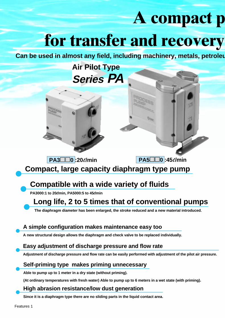
PA3��0 :20l/min
Can be used in almost any field, including machinery, metals, petroleu
PA5��0 :45l/min
Compact, large capacity diaphragm type pump
Long life, 2 to 5 times that of conventional pumps The diaphragm diameter has been enlarged, the stroke reduced and a new material introduced.
A simple configuration makes maintenance easy tooA new structural design allows the diaphragm and check valve to be replaced individually.
Self-priming type makes priming unnecessaryAble to pump up to 1 meter in a dry state (without priming).
(At ordinary temperatures with fresh water) Able to pump up to 6 meters in a wet state (with priming).
Easy adjustment of discharge pressure and flow rateAdjustment of discharge pressure and flow rate can be easily performed with adjustment of the pilot air pressure.
High abrasion resistance/low dust generationSince it is a diaphragm type there are no sliding parts in the liquid contact area.
Air Pilot Type
Series PA
Compatible with a wide variety of fluidsPA3000:1 to 20l/min, PA5000:5 to 45l/min
A compact pfor transfer and recovery
Features 1

Features 2
um, painting, printing, chemistry, foods, semiconductors and electrical.
��
ump suitable of a wide variety of fluids
Transfer of liquid by suction Transfer of liquid by pressureAtomizing of liquid Stirring of liquid
Pump with built-in micro-solenoid valve
PAX1��2 :10l/min1
• The suction lift is a maximum of 6m. (with priming)
• Use caution regarding the suction port seal.• Increases the discharge pressure of the discharge nozzle.
• For stirring of liquids that may stick.
Built-in pulsation attenuator (standard)
Built-in pulsation attenuator
Series PAXBuilt-in solenoid valve
Series PB
Application examples
A pulsation attenuating function to suppress discharge pressure pulsation is a new built-in feature.This controls problems such as discharge piping vibration, scattering of liquid from the discharge outlet, and foaming in tanks.In addition, internalization of this feature makes it unnecessary to provide extra space and separate piping, etc.
A solenoid valve drive type diaphragm pump that fits in the palm of the hand
• Polypropylene body: 60 x 60 x 41• Maximum discharge: 2l/min• Connection port size: Rc(PT)1/8
• Space is saved due to the centralization of piping and wiring areas on the top and bottom surfaces.
• Simple adjustment of the discharge flow rate
Adjustment of the discharge flow rate can be easily performed with the number of ON/OFF cycles of the internal solenoid valve (VJ300).
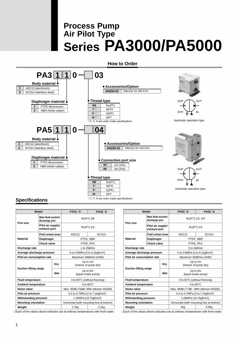
How to Order
Specifications
0PA312
Body materialADC12 (aluminium)SCS14 (stainless steel)
03
AN200-02Accessories/Option
Silencer for AIR EXH
Automatic operation type
OUTSUP
EXH IN
Automatic operation type
∗ T, F, N are order made specifications.
NilT ∗
F ∗
N ∗
Thread typeRc(PT)NPTFG(PF)NPT
12
Diaphragm materialPTFE (fluororesin)NBR (nitrile rubber)
0PA5
12
Body materialADC12 (aluminium)SCS14 (stainless steel)
0406
Connection port size1/2 (15A)3/4 (20A)
∗ T, F, N are order made specifications.
NilT*
F*
N*
Thread typeRc(PT)NPTFG(PF)NPT
Model PA31�0
Rc(PT) 3/8
Rc(PT) 1/4
PTFE, NBR
PTFE, PFA
1 to 20l/min
0 to 0.6MPa (0 to 6.1kgf/cm²)
Maximum 200l/min (ANR)
Up to 1m(interior of pump dry)
Up to 6m(liquid inside pump)
0 to 60°C (without freezing)
0 to 60°CMax. 92dB (79dB: With silencer AN200)
0.2 to 0.7MPa (2 to 7.1kgf/cm²)
1.05MPa (10.7kgf/cm²)
Horizontal (with mounting foot at bottom)
PA32�0
ADC12 SCS14
1.7kg 2.2kg
Port size
Main fluid suction/discharge port
Fluid contact areas
Diaphragm
Check valve
Pilot air supply/exhaust port
Dry
Wet
Material
Suction lifting range
∗ Each of the values above indicates use at ordinary temperatures with fresh water. ∗ Each of the values above indicates use at ordinary temperatures with fresh water.
Discharge rate
Average discharge pressure
Pilot air consumption rate
Fluid temperature
Ambient temperature
Noise value
Pilot air pressure
Withstanding pressure
Mounting orientation
Weight
12
Diaphragm materialPTFE (fluororesin)NBR (nitrile rubber)
Model PA51�0
Rc(PT) 1/2, 3/4
Rc(PT) 1/4
PTFE, NBR
PTFE, PFA
5 to 45l/min
0 to 0.6MPa (0 to 6.1kgf/cm²)
Maximum 300l/min (ANR)
Up to 2m(interior of pump dry)
Up to 6m(liquid inside pump)
0 to 60°C (without freezing)
0 to 60°CMax. 89dB (77dB : With silencer AN200)
0.2 to 0.7MPa (2 to 7.1kgf/cm²)
1.05MPa (10.7kgf/cm²)
Horizontal (with mounting foot at bottom)
PA52�0
ADC12 SCS14
3kg 6.5kg
Port size
Main fluid suction/discharge port
Fluid contact areas
Diaphragm
Check valve
Pilot air supply/exhaust port
Dry
Wet
Material
Suction lifting range
Discharge rate
Average discharge pressure
Pilot air consumption rate
Fluid temperature
Ambient temperature
Noise value
Pilot air pressure
Withstanding pressure
Mounting orientation
Weight
OUTSUP
EXH IN
1 1
1 1 04
AN200-02Accessories/Option
Silencer for AIR EXH
1
Process PumpAir Pilot Type
Series PA3000/PA5000

Fluid Compatibility
Fluid contact materials and models
Examples of applicable liquids (reference)
Models
1. Liquid contact area materials other than the above are: the check valve and O-ring seal which are both fluororesin.
Liquid contact area
Series PA3000
Series PA5000
Body
Diaphragm
Aluminum (ADC12)
Fluororesin
PA3110
PA5110
Nitrile rubber
PA3120
PA5120
Fluororesin
PA3210
PA5210
Nitrile rubber
PA3220
PA5220
Stainless steel (SCS14)
Diaphragm material:Fluororesin
Ethyl alcohol, Toluene,Cutting oil, Brake fluid
Methyl ethyl ketone, Acetone, Flux,Isopropyl alcohol, Inert fluorine solvent
Diaphragm material:Nitrile rubber
Body material: aluminium
Turbine oil Industrial water
Body material: stainless steel
Caution1. Select models by choosing liquid contact materials suitable for the liquids to be used.
• In liquid contact areas, aluminum is suitable for use with oils, and stainless steel is suitable for solvents and industrial water.
• For the diaphragm material, nitrile rubber is suitable with inert liquids, and fluororesin is suitable with non-permeating liquids.
• Use fluids which will not corrode the liquid contact materials.
2. Transfer examples are shown below. Since the possible applications will change depending on operating conditions, be sure to confirm by means of experimentation.
3. These products are not suitable for use in medical applications or with food products.
Caution1. Possible applications will change depending on additive agents. Take note of additives.2. Possible applications will change depending on impurities. Take note of impurities.3. Mixing of foreign substances will shorten service life. Operate with foreign substances removed.4. When transferring liquids subject to coagulation, take measures to prevent coagulation inside the pump.
Examples of noncompatible liquids (classification)
Diaphragm material:Fluororesin
Cleaning solvents, Water, Acid-alkali,High permeation liquids,
High penetration liquids, Corrosive liquids
Corrosive liquids, Acid-alkali,High permeation liquids, High penetration liquids
Cleaning solvents, Water, Solvents,Acid-alkali, Corrosive liquids
Solvents, Corrosive liquids,Acid-alkali
Diaphragm material:Nitrile rubber
Body material: aluminium Body material: stainless steel
Process Pump Air Pilot Type Series PA3000/5000
� � � �
2

Performance Curves
Required specification example:
Find the pilot air pressure and pilot air consumption rate for a discharge rate of 6l/min and a total lifting range of 25m. [The transfer fluid is fresh water (viscosity 1cp, specific gravity 1.0).]
1. First mark the intersection point for a discharge rate of 6l/min and a lifting range of 25m.
2. Find the pilot air pressure for the marked point. In this case, the point is between the discharge curves (solid lines) for SUP=0.2MPa and SUP=0.5MPa, and based on the proportional relationship to these lines, the pilot air pressure for this point is approximately 0.38MPa.
3. Next find the air consumption rate. Since the marked point is below the curve for 50l/min (ANR), the maximum rate will be about 50l/min (ANR).
Required specification example:
Find the pilot air pressure and pilot air consumption rate for a discharge rate of 2.7l/min, a total lifting range of 25m, and a viscosity of 100cp.
1. First find the ratio of the discharge rate to fresh water when viscosity is 100cp from the graph below. It is determined to be 45%.
2. Next, in the required specification example, the viscosity is 100cp and the discharge rate is 2.7l/min. Since this is equivalent to 45% of the discharge rate for fresh water, 2.7l/min ÷ 0.45 = 6l/min, indicating that a discharge rate of 6l/min is required.
3. Finally, find the pilot air pressure and pilot air consumption rate based on selections from the flow rate characteristic graphs.
Selection from Flow Rate Characteristic Graphs Selection from Viscosity Characteristic Graph
Viscosity characteristics (flow rate correction for viscous fluids)
Caution1. These flow rate characteristics are for fresh water (viscosity 1cp,
specific gravity 1.0).
2. The discharge rate differs greatly depending on properties (viscosity, specific gravity) of the fluid being transferred and operating conditions (lifting range, transfer distance), etc.
3. Use 0.75kW per 100l/min of air consumption as a guide for the relationship of the air consumption rate to the compressor.
Caution1. Viscosities up to 1000cp can be used.
PA3000 Flow rate characteristics PA5000 Flow rate characteristics
60
50
40
30
20
10
0
Discharge rate l/min
Tot
al li
fting
ran
ge (
m)
SUP=0.7MPa
SUP=0.5MPa
SUP=0.2MPa
Air consumption 100l/m
in (ANR)
Air consumption 50l/m
in (ANR)
SUP=0.7MPa
SUP=0.5MPa
SUP=0.2MPa
Air consumption 200l/m
in (ANR)
Air consumption 100l/m
in (ANR)
10 20
60
50
40
30
20
10
0
Discharge rate l/min
Tot
al li
fting
ran
ge (
m)
10 30 40 5020 60
100
50
01 10 100 1000
Viscosity (cp)
Rat
io o
f dis
char
ge r
ate
to fr
esh
wat
er (
%)
Series PA3000/5000
3

Operating Principle
When air is supplied, it passes through the switching valve and enters drive chamber A. When air enters drive chamber A, diaphragm A moves to the left, and at the same time diaphragm B also moves to the left pushing pilot valve B. When pilot valve B is pressed, air acts upon the switching valve and this time drive chamber B is switched to a supply state. At this time, the air which was in drive chamber A goes through the exhaust passage and is exhausted to the outside. When air enters drive chamber B, diaphragm A moves to the right pressing pilot valve A. When pilot valve A is pressed, the air which was acting upon the switching valve is exhausted, and drive chamber A once again switches to a supply state. A contiuous reciprocal motion is generated by this repetition.
When air enters drive chamber A, the fluid in pump chamber A is pushed out. At the same time, fluid is sucked into pump chamber B. When the diaphragm moves in the opposite direction, the fluid in pump chamber B is pushed out, and fluid is sucked into pump chamber A. Continuous suction/discharge is performed by the reciprocal motion of the diaphragm.
Main pump unitPilot air switching unit
Switching valve
Pilot valve A Pilot valve B
Diaphragm BDiaphragm A Drive chamber A Drive chamber B
Check valve Shaft
Pump chamber BPump chamber A
Air supply port(AIR SUP)
Exhaust port(AIR EXH)
Discharge port(FLUID OUT)
Suction port(FLUID IN)
Pilo
tAi
r sw
itchi
ng u
nit
Mai
n pu
mp
unit
4
Process Pump Air Pilot Type Series PA3000/5000
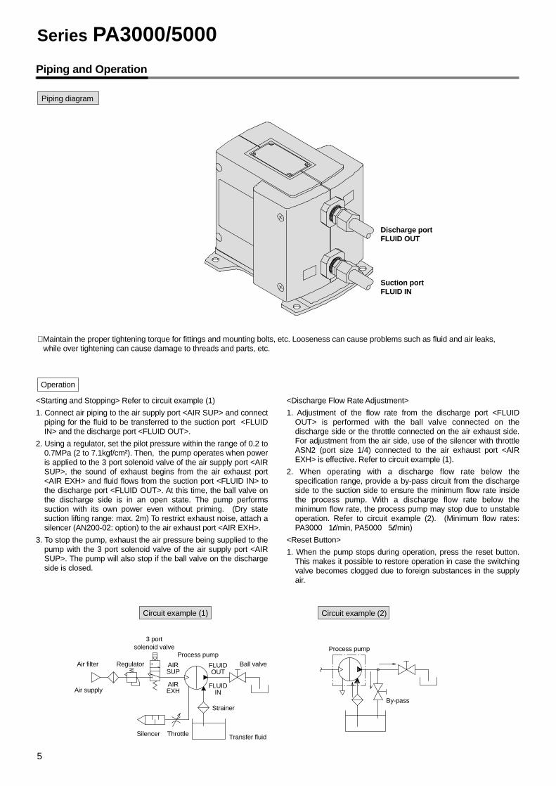
Piping and Operation
∗ Maintain the proper tightening torque for fittings and mounting bolts, etc. Looseness can cause problems such as fluid and air leaks, while over tightening can cause damage to threads and parts, etc.
<Starting and Stopping> Refer to circuit example (1)
1. Connect air piping to the air supply port <AIR SUP> and connect piping for the fluid to be transferred to the suction port <FLUID IN> and the discharge port <FLUID OUT>.
2. Using a regulator, set the pilot pressure within the range of 0.2 to 0.7MPa (2 to 7.1kgf/cm²). Then, the pump operates when power is applied to the 3 port solenoid valve of the air supply port <AIR SUP>, the sound of exhaust begins from the air exhaust port <AIR EXH> and fluid flows from the suction port <FLUID IN> to the discharge port <FLUID OUT>. At this time, the ball valve on the discharge side is in an open state. The pump performs suction with its own power even without priming. (Dry state suction lifting range: max. 2m) To restrict exhaust noise, attach a silencer (AN200-02: option) to the air exhaust port <AIR EXH>.
3. To stop the pump, exhaust the air pressure being supplied to the pump with the 3 port solenoid valve of the air supply port <AIR SUP>. The pump will also stop if the ball valve on the discharge side is closed.
<Discharge Flow Rate Adjustment>
1. Adjustment of the flow rate from the discharge port <FLUID OUT> is performed with the ball valve connected on the discharge side or the throttle connected on the air exhaust side. For adjustment from the air side, use of the silencer with throttle ASN2 (port size 1/4) connected to the air exhaust port <AIR EXH> is effective. Refer to circuit example (1).
2. When operating with a discharge flow rate below the specification range, provide a by-pass circuit from the discharge side to the suction side to ensure the minimum flow rate inside the process pump. With a discharge flow rate below the minimum flow rate, the process pump may stop due to unstable operation. Refer to circuit example (2). (Minimum flow rates: PA3000 1l/min, PA5000 5l/min)
<Reset Button>
1. When the pump stops during operation, press the reset button. This makes it possible to restore operation in case the switching valve becomes clogged due to foreign substances in the supply air.
Operation
Circuit example (1)
Air filter Ball valveProcess pump
Process pump
By-passStrainer
Silencer Throttle Transfer fluid
AIRSUP
AIREXH
FLUIDOUT
FLUIDINAir supply
Regulator
3 portsolenoid valve
Circuit example (2)
Piping diagram
Discharge portFLUID OUT
Suction portFLUID IN
Series PA3000/5000
5

Dimensions
PA3000
PA5000
FLUIDOUT
AIRSUP
RESET
AIREXH
AIRSUP
AIREXH
FLUIDI N
FLUID OUT
FLUID I N
PROCESSPUMP
5.5
Reset button
AIR SUP(pilot air supply port)
Rc(PT) 1/4
Rc(PT) 1/4
AIR EXH(pilot air exhaust port)
2
100130
3
FLUID INRc(PT) 3/8
FLUID OUTRc(PT) 3/8
44.5
5616556
112
202114 3.53
58.5
103.
5
125.
5
167
48.5
132.
5
74.5
115
90
32
PROCESSPUMP
AIR SUP(pilot air supply port)
Rc(PT) 1/4
Reset button
FLUID INRc(PT) 1/2, 3/4
FLUID OUTRc(PT) 1/2, 3/4
Rc(PT) 1/4
AIR EXH(pilot air exhaust port)
(185)
1054-ø7 7.5
68 85
179 4-ø9
(257)
90 90
6
Process Pump Air Pilot Type Series PA3000/5000

How to Order
SpecificationsPerformance Curves
1 2PAX1
12
Body materialADC12 (aluminium)SCS14 (stainless steel)
0203
Connection port size1/4 (8A)3/8 (10A)
∗ T, F, N are order made specifications.
NilT ∗
F ∗
N ∗
Thread typeRc(PT)NPTFG(PF)NPT
1
Diaphragm materialPTFE (fluororesin)
2
Type of operationAutomatic operation type withbuilt-in pulsation attenuator
Model PAX1112
Rc(PT) 1/4, 3/8
Rc(PT) 1/4
PTFE
PTFE, SCS14
0.5 to 10l/min
0 to 0.6MPa (0 to 6.1kgf/cm²)
Maximum 150l/min (ANR)
Up to 2m(interior of pump dry)
Up to 6m(liquid inside pump)
30% or less of maximum discharge pressure
0 to 60°C (without freezing)
0 to 60°CMax. 93dB (84dB : With silencer AN200)
0.2 to 0.7MPa (2 to 7.1kgf/cm²)
1.05MPa (10.7kgf/cm²)
Horizontal (bottom facing down)
PAX1212
ADC12 SCS14
2.0kg
∗ Each of the values above indicates use at ordinary temperatures with fresh water.
3.5kg
Port size
Main fluid suction/discharge port
Fluid contact areas
Diaphragm
Check valve
Pilot air supply/exhaust port
Dry
Wet
Material
Suction lifting range
Discharge rate
Average discharge pressure
Pilot air consumption rate
Discharge pulsation attenuating capacity
Fluid temperature
Ambient temperature
Noise value
Pilot air pressure
Withstanding pressure
Mounting orientation
Weight
70
60
50
40
30
20
10
0 5
Discharge rate l/min
Tot
al li
fting
ran
ge (
m)
SUP=0.7MPa
SUP=0.5MPa
SUP=0.2MPa
Air consumption 50l/m
in(ANR)
Air consumption 30l/min(ANR)
10
1 02
JIS symbol
Built-in Pulsation AttenuatorAutomatic operation type
OUTSUP
EXH IN
AN200-02Accessories/Option
Silencer for AIR EXH
7
Process PumpBuilt-in Pulsation Attenuator Type
Series PAX1000

Fluid Compatibility
Fluid contact materials and models
Examples of applicable liquids (reference)
Models
1. Liquid contact area materials other than the above are: check valve/stainless steel (SCS14), and O-ring seal/fluororesin (PTFE).
Liquid contact area
Series PAX1000
Body
Diaphragm
Aluminium (ADC12)
Fluororesin
PAX1112
Fluororesin
PAX1212
Stainless steel (SCS14)
Diaphragm material:Fluororesin
Ethyl alcohol, Toluene,Cutting oil, Brake fluid
Methyl ethyl ketone, Acetone, Flux,Isopropyl alcohol, Inert fluorine solvent
Body material: aluminium Body material: stainless steel
Caution1. Select models by choosing liquid contact materials suitable for the liquids to be used.
• In liquid contact areas, aluminum is suitable for use with oils, and stainless steel is suitable for solvents and industrial water.
• Since fluororesins is used for the diaphragm, non-permeating liquids should be used.
• Use fluids which will not corrode the liquid contact materials.
2. Transfer examples are shown below. Since the possible applications will change depending on operating conditions, be sure to confirm by means of experimentation.
3. These products are not suitable for use in medical applications or with food products.
Caution1. Possible applications will change depending on additive agents. Take note of additives.2. Possible applications will change depending on impurities. Take note of impurities.3. Mixing of foreign substances will shorten service life. Operate with foreign substances removed.4. When transferring liquids subject to coagulation, take measures to prevent coagulation inside the pump.
Examples of noncompatible liquids (classification)
Diaphragm material:Fluororesin
Cleaning solvents, Water, Acid-alkali, High permeation liquids,
High penetration liquids, Corrosive liquids
Corrosive liquids, Acid-alkali,High permeation liquids, High penetration liquids
Body material: aluminum Body material: stainless steel
8
Process Pump Built-in Pulsation Attenuator Type Series PAX1000

Piping
Construction and Principles
Piping diagram
Circuit example (1)
Caution
Pilot air supply port
AIR SUP
Pilot air exhaust port
AIR EXH
Silencer
Reset button Reset button
Discharge portFLUID OUT
Suction portFLUID IN
Air filter
Process pumpPAX1�12
Strainer
Silencer ThrottleTransfer fluid
AIRSUP
AIREXH
FLUIDOUT
FLUIDINAir supply
Regulator Ball valve
3 portsolenoid valve
Switching valveChange lever
Pulsation attenuatorintake valve
Control unit
Drive unit
Pulsation attenuator air chamber
Pulsationattenuation chamber
Pump chamber B
Pump chamber A
Check valve
Drive chamber BDrive chamber ADiaphragm A
Shaft
Pilot valve B
Pulsation attenuator exhaust valve
Pilot valve A
Air supply port(AIR SUP)
Discharge port(FLUID OUT)
Suction port(FLUID IN)
Air exhaust port(AIR EXH)
PROCESS PUMP
Maintain the proper tightening torque for fittings and mounting bolts, etc. Looseness can cause problems such as fluid leakage, while over tightening can cause damage to threads and parts, etc.
• Piping is connected to each of 4 ports as shown in the drawing above.
Series PAX1000
9

Pulsation Attenuating Capacity
Dimensions
Without pulsation attenuator
With built-in pulsation attenuator
The process pump generates pulsation because it discharges a liquid using two diaphragms. The pulsation attenuator absorbs pressure when discharge pressure increases, and compensates the pressure when discharge pressure decreases. By this means pulsation is controlled.
AIR SUP(pilot air supply port)Rc(PT) 1/4
AIR EXH(pilot air exhaust port) Rc(PT) 1/4
(175)
120
Bottom
32.5 45.5
FLUID INRc(PT) 1/4, 3/8FLUID OUTRc(PT) 1/4, 3/8
75 5
23
1057.5
Mounting hole detail
Reset button
110
33
4529
125
100
69
10.5
FLUIDIN
AIRSUP
AIREXH
FLUIDOUT
PROCESS PUMP
RESET
Automatic operation typewith built-in pulsation attenuator
OUTSUP
EXH IN
0.5
0.7
MPa
MPa
0.5
00
0.7
4-M8 (M6 hexagon socket head screw
can be inserted)
10
Process Pump Built-in Pulsation Attenuator Type Series PAX1000

How to Order
Specifications
1 0 1 01PB
1Body size
1/8 standard
Foot (bolts included)
01
Connection port size1/8 (6A)
NilT ∗F ∗N ∗
Thread typeRc(PT)NPTFG(PF)NPT
0
Body materialPolypropylene 1
Diaphragm materialPTFE (fluororesin)
13
Type of operationBuilt-in solenoid valveExternal air operated
Rc(PT) 1/8
Rc(PT) 1/8
M5 x 0.8
Polypropylene PP, Stainless steel (SUS316)
PTFE
PTFE
FKM
8 to 2000ml/min
8 to 500ml/min
0 to 0.6MPa {0 to 6.1kgf/cm²}
Up to 2.5m
0 to 50°C (without freezing)
0 to 50°C0.2 to 0.7MPa {2 to 7.1kgf/cm²}
1.05MPa (10.7kgf/cm²)
10c/s
Not required
24VDC
0.17kg
OUT port at top (indication on name plate)
Port size
Main fluid suction/discharge port
Fluid contact areas
Diaphragm
Check valve
Liquid contact seals
Pilot air
Symbol
Supply port
Exhaust port
PB1011
PB1013
Material
Average discharge pressure
Suction lifting range (Dry: interior of the pump is dry)
Fluid temperature
Ambient temperature
Pilot air pressure
Withstanding pressure
Maximum operating frequency
Lubrication
Voltage (PB1011)
Weight
Mounting orientation
1
OUTSUPEXH
IN
∗ T, F, N are order made specifications.
Discharge rate
∗ Each of the values above indicates use at ordinary temperatures with fresh water.Note on the transfer of slurry: Slurry transfer is not possible with Series PB1000 because of deterioration and wear of the check valve seat and the accumulation of particles, which will render the pump inoperable.
AN120-M5KT-PB1-3
Accessories/OptionSilencer for AIR EXH ∗
∗ External air operated type is not available with silencer.
11
Process PumpBuilt-in Solenoid Valve Type
Series PB1000
Fluid Compatibility
Liquid contact parts tableLiquid contact part description
Diaphragm
Body
Seals
Liquid contact part material
Fluororesin
Polypropylene, SUS316
Fluororubber
Caution1. Give careful consideration to the transfer fluid to be used and the
fluid contact materials.
• Since fluororesin is used for the diaphragm material, use liquids which will not permeate or penetrate it.
• Since there is a built-in solenoid valve, this product cannot be used for the transfer of flammable fluids. (PB1011)
• Use fluids which will not corrode the liquid contact materials.
2. These products are not suitable for use in medical applications or with food products.
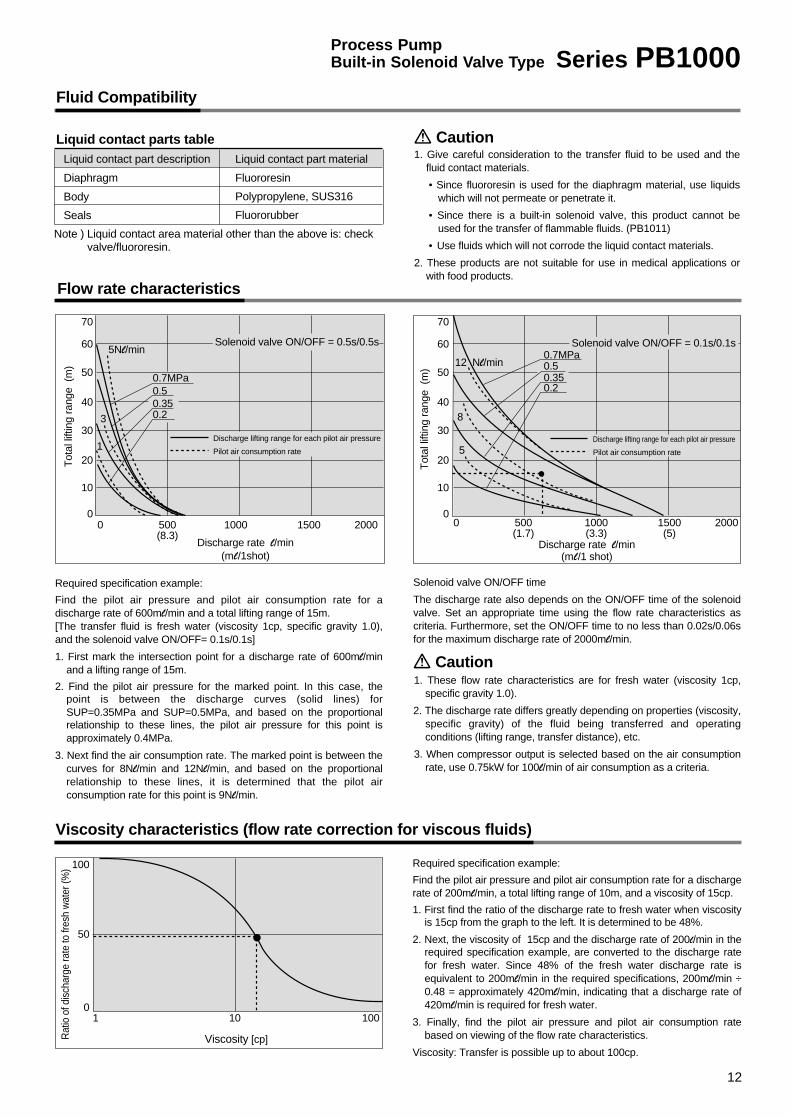
Flow rate characteristics
70
60
50
40
30
20
10
00 500
(8.3) Discharge rate l/min
(ml/1shot)
Tot
al li
fting
ran
ge (
m)
1000
0.7MPa
3
1
5Nl/min12 Nl/min
8
5Discharge lifting range for each pilot air pressure
Pilot air consumption rate
0.50.350.2
0.7MPa0.50.350.2
1500 2000
70
60
50
40
30
20
10
00 500
(1.7) Discharge rate l/min
(ml/1 shot)
Tot
al li
fting
ran
ge (
m)
1000 (3.3)
1500 (5)
2000
Discharge lifting range for each pilot air pressure
Pilot air consumption rate
Required specification example:
Find the pilot air pressure and pilot air consumption rate for a discharge rate of 600ml/min and a total lifting range of 15m. [The transfer fluid is fresh water (viscosity 1cp, specific gravity 1.0), and the solenoid valve ON/OFF= 0.1s/0.1s]
1. First mark the intersection point for a discharge rate of 600ml/min and a lifting range of 15m.
2. Find the pilot air pressure for the marked point. In this case, the point is between the discharge curves (solid lines) for SUP=0.35MPa and SUP=0.5MPa, and based on the proportional relationship to these lines, the pilot air pressure for this point is approximately 0.4MPa.
3. Next find the air consumption rate. The marked point is between the curves for 8Nl/min and 12Nl/min, and based on the proportional relationship to these lines, it is determined that the pilot air consumption rate for this point is 9Nl/min.
Solenoid valve ON/OFF time
The discharge rate also depends on the ON/OFF time of the solenoid valve. Set an appropriate time using the flow rate characteristics as criteria. Furthermore, set the ON/OFF time to no less than 0.02s/0.06s for the maximum discharge rate of 2000ml/min.
1. These flow rate characteristics are for fresh water (viscosity 1cp, specific gravity 1.0).
2. The discharge rate differs greatly depending on properties (viscosity, specific gravity) of the fluid being transferred and operating conditions (lifting range, transfer distance), etc.
3. When compressor output is selected based on the air consumption rate, use 0.75kW for 100l/min of air consumption as a criteria.
Viscosity characteristics (flow rate correction for viscous fluids)
Required specification example:
Find the pilot air pressure and pilot air consumption rate for a discharge rate of 200ml/min, a total lifting range of 10m, and a viscosity of 15cp.
1. First find the ratio of the discharge rate to fresh water when viscosity is 15cp from the graph to the left. It is determined to be 48%.
2. Next, the viscosity of 15cp and the discharge rate of 200l/min in the required specification example, are converted to the discharge rate for fresh water. Since 48% of the fresh water discharge rate is equivalent to 200ml/min in the required specifications, 200ml/min ÷ 0.48 = approximately 420ml/min, indicating that a discharge rate of 420ml/min is required for fresh water.
3. Finally, find the pilot air pressure and pilot air consumption rate based on viewing of the flow rate characteristics.
Viscosity: Transfer is possible up to about 100cp.Viscosity [cp]
100
50
01 10 100
Rat
io o
f dis
char
ge ra
te to
fres
h w
ater
(%)
Caution
Note ) Liquid contact area material other than the above is: check valve/fluororesin.
Solenoid valve ON/OFF = 0.5s/0.5s Solenoid valve ON/OFF = 0.1s/0.1s
12
Process Pump Built-in Solenoid Valve Type Series PB1000

Piping and Operation
Names and Functions of Ports
Piping is connected to each of 4 ports as shown in the drawing to the left.The solenoid valve lead wires are connected to a 24VDC power supply.
Circuit example
Piping
Discharges the pilot air.
Connect to 24VDC power supply. Red (+), Black (–)
Operation
IN Suction Port
Discharge Port
Pilot Air Supply Port
Pilot Air Exhaust Port
OUT
SUP
Solenoid Valve Lead Wires
Manual Override Pin
EXH
1234
Caution
Dis
char
ge p
ort O
UT
Suc
tion
port
IN
Air
supp
ly p
ort S
US
Air
exha
ust p
ort E
XH
Sol
enoi
d va
lve
lead
wire
s
Foot(optional)
Manual override pinTop view
ON/OFF signal
EXHFilter
Air supply
Process pumpPB1011
Transfer fluid
Regulator OUT
SUP IN
(V)240
Connect air piping to the air supply port SUP, and connect piping for the transfer fluid to the suction port IN and the discharge port OUT.
Connect the solenoid valve lead wires to a 24VDC power supply. Red is (+) and Black is (–).
Using a regulator, set the pilot air pressure within the range of 0.2 to 0.7MPa (2 to 7kgf/cm²). By continuously turning the 24VDC power ON/OFF the fluid flows from the suction port IN to the discharge port OUT. The pump performs suction with its own power even without priming.
To stop the pump turn OFF the 24VDC power. Also be sure to turn OFF the power when the discharge side is closed.
Be sure that the discharge side OUT is on top when the pump is mounted.Supply clean air that has passed through an AF filter, etc. to the air supply port SUP.Air that contains debris or drainage, etc. will have an adverse effect on the built-in solenoid valve, and will cause malfunction of the pump. In cases that particularly require air cleaning, use a filter (Series AF) together with a mist separator (Series AM).
Connects to piping for the transfer fluid.
Discharges the fluid which has been sucked into the pump.
Supplies the pressure which is set by a regulator, etc. Use clean air.
Presses the manual override button for the solenoid valve. Pushing once operates the valve one time without turning on the power.
Series PB1000
13

Construction and Operation
Dimensions
PB1000
Operating Principle
When air is supplied and the built-in solenoid valve is turned ON, air enters the drive chamber and the diaphragm moves to the left. Due to this movement, the fluid in the pump chamber passes through the upper check valve and is discharged to the OUT side.
When the solenoid valve is turned OFF, the air inside the drive chamber is evacuated to EXH, and the diaphragm is moved to the right by the return force of the return spring. Due to this movement, the fluid on the IN side passes through the lower check valve and is sucked into the pump chamber.
The pump repeats this suction and discharge with the repetition of the solenoid valve's ON/OFF operation.
Discharge port OUT
Diaphragm
Return spring
Built-in solenoid valve
SUPPilot air supply port
EXHPilot air exhaust port
Suction port IN
OUT port Rc(PT) 1/8Discharge port
Mount with this surface (OUT port side) on top
11
�60
IN port
Suction port Rc(PT) 1/8
SUP (Pilot air supply) portRc(PT) 1/8
2-M4 x 0.7Female threads for mounting
Thread depth 6
EXH (pilot air exhaust) port M5 x 0.8 Thread depth 10
41
84
72
45
16
2-ø4.5Mounting hole
2-M4 x 0.7Female threads for mountingThread depth 6
17.5
22
45
139
11
7.5
11
(78
.1) 57
18.511
32
16
Drive chamber
Pump chamber
OUT
�UP SIDEMounting position
MODEL PB1011
SUPPLY PRESSAIR 0.2 to 0.7MPaVOLTAGE
SUPIN
EXH
DC ONOFF
PROCESSPUMP
MADE IN JAPAN
14
Process Pump Built-in Solenoid Valve Type Series PB1000

Related Products (Refer to the individual product catalogs for further details.)
Maintenance Parts Lists
How to Order
Series AN200
Series AM
Noise reduction of 30dB (A) or moreLow air flow resistanceCompact and easy to mount
Mist Separator
Series AC2040, 3040Filter Regulator + Mist SeparatorAir Combination
FluidMaximum operating pressureNoise reductionAmbient and fluid temperature
Specifications
Specifications
Standard specifications
Construction/Parts, DimensionsAN200
ModelsJIS symbol
Compressed air1.0MPa {10.2kgf/cm²}
30dB (A) or more5 to 60°C ∗
FluidMaximum operating pressureMin. operating pressure*
Proof pressure
Ambient and fluid temperature
Filtration degree
Downstream oil mist concentration
Element life
∗ N.O. with auto drain is 0.15MPa (1.5kgf/cm²)∗ When compressor discharge oil mist concentration is 30mg/m³ (ANR)
Compressed air1.0MPa {10.2kgf/cm²}0.05MPa {0.51kgf/cm²}1.5MPa {15.3kgf/cm²}
5 to 60°C
0.3µm (95% filtered particle diameter)
Max.1.0mg/m³ (ANR) ∗(Approx. 0.8ppm)
2 years, or when pressure drop reaches 0.1MPa {1.0kgf/cm²}
Body size150 – 1/8 standard250 – 1/4 standard350 – 3/8 standard450 – 1/2 standard550 – 3/4 standard650 – 1 standard850 – 1 1/2 standard
Order made specification ∗
J – Drain guide 1/4B female threadsR – IN, OUT in opposite directionsT – Clogging checker
Accessories (optional) ∗
Port size01 – 1/8B
02 – 1/4B
03 – 3/8B
04 – 1/2B
06 – 3/4B
10 – 114 – 1 1/2B
20 – 2B
Thread typeNil ––––– Rc(PT)F ––––––– G(PF)N ––––––– NPT
Model Port sizeR(PT)
1/4
Weightg
17
Effective sectional area mm²
35AN200-02
(BC Sintered Body)
Series AN120 Ideal for compact valves andpilot air exhaust, etc.
FluidMaximum operating pressureNoise reductionAmbient and fluid temperature
Specifications Construction/Parts, DimensionsAN120
Models
Compressed air1.0MPa {10.2kgf/cm²}
18dB (A) 5 to 150°C ∗
Model Port sizeR(PT)
M5
Weightg
3.3
Effective sectional area mm²
5AN120-M5
ModelsModel
AM 250 03 B J
Model AC2040
1/81/4
1/8 1/8
1/43/8
AC3040
AW2000AFM2000
AW3000AFM3000
Componentdevices
Filter regulatorMist separator
Port size Rc(PT)
Pressure gauge port size Rc(PT)
AM150
Description
–
Bracket
N.C. auto drain
N.O. auto drain
Symbol
Nil
B
C
D
AM250
300 750
1/8, 1/4, 3/8 1/4, 3/8, 1/2
0.38 0.55
Rated flow ratel/min (ANR)
Port size(nominal size B)
Weight (kg)
JIS symbol
Diaphragm kit (PTFE)
Check valve kit
Switching valve parts kit
Pilot valve kit
Pulsation attenuator control valve kit
KT-PAX1-31
KT-PAX1-36
KT-PAX1-37
KT-PA5-38
KT-PAX1-39
PAX1000
Diaphragm kit
Check valve kit
Built-in solenoid valve kit
KT-PB1-2
KT-PB1-1
VJ314MY-5H
PB1000
Diaphragm kit (PTFE)
Diaphragm kit (NBR)
Check valve kit
Switching valve assembly kit
Pilot valve kit
KT-PA3-31
KT-PA3-32
KT-PA3-36
KT-PA3-37
KT-PA5-38
PA3000Diaphragm kit (PTFE)
Diaphragm kit (NBR)
Check valve kit
Switching valve parts kit
Pilot valve kit
KT-PA5-31
KT-PA5-32
KT-PA5-36
KT-PA5-37
KT-PA5-38
PA5000
ø8
BC sintered body
Phosphor bronze
Port size
17
ø22 End plate(polyacetal)
Case(polyacetal)
Hexagon section width across flats19
Port size
Sound absorbing material(PE sintered body)
63
∗ Can be used at -10 to 150°C when there is no danger of water droplets being generated from the fluid.
∗ Can be used at -10 to 60°C when there is no danger of water droplets being generated from the fluid and freezing.
Series AM separates and removes the oil mist in compressed air which is troublesome for ordinary filters, and removes fine particles of rust and carbon, etc. of 0.3µm or larger. Should be used with an air supply for driving pilot type and metal type solenoid valves.
∗ Refer to the table below regarding the combination of accessories with order made specifications.
Related Products
15

Process Pump
Safety Instructions
Note 1) ISO4413: Hydraulic fluid power-General rules for the application of equipment to transmission and control systems.Note 2) ISO4414: Pneumatic fluid power -- Recommendations for the application of equipment to transmission and control systems.Note 3) JISB8361: Hydraulic system axiomNote 4) JISB8370: Pneumatic system axiom.Note 5) JISZ9102: Piping identification marking
Warning
Caution : Operator error could result in injury or equipment damage.
Warning : Operator error could result in serious injury or loss of life.
Danger : In extreme conditions, there is a possible result of serious injury or loss of life.
These safety instructions are intended to prevent a hazardous situation and/or equipment damage. These instructions indicate the level of potential hazard by a label of "Caution", "Warning" or "Danger". To ensure safety, be sure to observe ISO4413 Note 1), ISO4414 Note 2), JISB8361 Note 3), JISB8370 Note 4), JISZ9102 Note 5)
and other safety practices.
1. The compatibility of pneumatic equipment is the responsibility of the person who designs the pneumatic system or decides its specifications.Since the products specified here are used in various operating conditions, their compatibility for the specific pneumatic system must be based on specifications or after analysis and/or tests to meet your specific requirements. Give particularly careful consideration to the determination of compatible fluids.
2. Only trained personnel should operate pneumatically operated machinery and equipment.Compressed air can be dangerous if an operator is unfamiliar with it. Assembly, handling or repair of pneumatic systems should be performed by trained and experienced operators.
3. Do not service machinery/equipment or attempt to remove components until safety is confirmed.
1. Inspection and maintenance of machinery/equipment should only be performed after confirmation of safe locked-out control positions.
2. When equipment is to be removed, confirm the safety process as mentioned above. Cut the supply pressure for this equipment and exhaust all residual compressed air in the system.
3. Before machinery/equipment is restarted, take measures to prevent shooting-out of cylinder piston rod, etc. (Bleed air into the system gradually to create back-pressure.)
4. Contact SMC if the product is to be used in any of the following conditions:1. Conditions or environments beyond the specifications given in the catalog and instruction manual.2. With fluids whose application causes concern due to type or additives, etc.3. Installation on equipment in conjunction with atomic energy, railway, air navigation, vehicles, medical
equipment, food and beverages, recreation equipment, emergency stop circuits, press applications, or safety equipment.
4. An application which has the possibility of having negative effects on people, property, or animals, requiring special safety analysis.
16

Process Pump Common Precautions 1Be sure to read before handling.Refer to the main catalog sections for detailed precautions on each series.
1. Confirm the fluid to be used.Be sure to confirm the specifications, as the fluids to be used dif-fer depending on the product. When different fluids are used,characteristics change and this can cause faulty operation.
2. Fluid temperature.Use each model within its respective fluid temperature range.
3. Fluid quality.If fluid is used which contains foreign matter, troubles such asmalfunction and seal failure may occur due to wearing of valveseats and sticking, etc. Install a suitable filter (strainer) immedi-ately before the pump. As a general rule, mesh of about 80 to 100can be used.
4. Be sure to observe the maximum operatingpressure.Operation above the maximum operating pressure can causedamage. In particular, avoid application of pressure above thespecifications caused by a water hammer.
<Example Pressure Reduction Measures>
a) Use a water hammer relief valve and slow the valve's closingspeed.
b) Absorb impact pressure by using elastic piping material suchas rubber, or an accumulator, etc.
5. Liquid seals.In cases with a flowing liquid, provide a by-pass valve in the sys-tem to prevent the liquid from entering the liquid seal circuit.
6. Quality of operating air.1. Use clean air.
Do not use compressed air which contains chemicals, syn-thetic oils containing organic solvents, salts or corrosivegases, etc., as these can cause damage or malfunction.
2. Install an air filter.
Install an air filter near valves on their upstream side. Choosea filtration degree of 5µm or finer.
3. Compressed air which includes a large amount of drainagecan cause malfunction of valves and other pneumatic equip-ment. As a countermeasure, install and air dryer or after cool-er, etc.
4. In situations where a large amount of carbon dust is generat-ed, install a mist separator at the upstream side of valves toremove it. When a lot of carbon dust is generated from a com-pressor, it can adhere to the interior of valves and cause mal-function.
Refer to the SMC "Air Cleaning Equipment" catalog for details onthe above mentioned air quality.
7. Ensure space for maintenance.Be sure to allow the space required for maintenance activities.
8. Fluid properties.1. Do not use strong acids, strong alkali or chemicals which can
effect humans.
2. When inflammable fluids are transferred, give consideration toleakage during operation, and strictly prohibit flames. There isa danger of fire or explosion due to accidental leakage of thefluid.
Precautions on Design
Warning
17
Warning
9. Stopping the pump.Use a 3 port solenoid valve when starting or stopping the pumpby means of pilot air. Do not use a 2 port solenoid valve. (In thecase of a 2 port solenoid valve, the air pressure which remainsafter the solenoid valve closes is gradually consumed inside theprocess pump. This causes instability in the operating position ofthe pilot air switching unit, and it may become inoperable. Sincethe same kind of problem also occurs when the air supply pres-sure is gradually lost after operation is stopped, a 3 port solenoidvalve should be used for stopping. When the unit will not berestarted, press the reset button.)
10.Other.1. Test the unit before using it in an actual equipment application.
Furthermore, even if there is no problem in a short term test,there are cases in which trouble is caused by permeationthrough the fluororesin diaphragm to the air side.
2. Since the compatibility of fluids differs depending on type,additives, concentration and temperature, etc., give carefulattention to the selection of materials.
3. The product cannot be used with gases.
Selection
1. Use a design which prevents reverse pres-sure and reverse flow.If reverse pressure or flow occur, this can cause equipment dam-age or malfunction, etc. Give attention to safety measures, includ-ing the method of operation.
1. Confirm the specifications.Give careful consideration to operating conditions such as theapplication, fluid and environment, and use within the operatingranges specified in this catalog.
2. Type of fluid.Operate only after confirming the materials and applicable fluidsfor each model to determine which fluids can be used.
3. Equipment selection.When selecting equipment, make a selection from the latest cat-alog, staying within specified operating ranges, and carefully con-firming the purpose of use, the required specifications and theoperating conditions (pressure, flow rate, temperature, environ-ment). In case of any unclear points, contact SMC in advance.
Caution

Process Pump Common Precautions 2Be sure to read before handling.Refer to the main catalog sections for detailed precautions on each series.
1. Instruction manual.The product should be mounted and operated after reading themanual carefully and having a good understanding of its con-tents. The manual should also be kept where it can be referredto whenever necessary.
2. Confirm the mounting position.• Since the mounting position is different for each piece of equip-
ment, this point should be confirmed either in this catalog or inthe instruction manual.
• The mounting orientation is limited. (Refer to the cover photo.)Mount with the bottom (foot hole or mounting hole side) facingdown.
• Since the reciprocal motion of the diaphragm propagates, themounting bolts should be tightened securely. Furthermore, incases where the propagation of vibration is not acceptable,insert vibro-isolating rubber when mounting.
3. Ensure sufficient maintenance space.When installing and mounting, be sure to allow the spacerequired for maintenance and inspections. Confirm the neces-sary maintenance space in the instruction manual for each pieceof equipment.
4. Do not drop or bump.Do not drop, bump or apply excessive impact (1000m/s²) whenhandling.
5. Never mount in a place which will be usedas a scaffold during piping work.Damage can be caused if subjected to an excessive load.
Mounting Piping
Warning
18
Caution
1. Do not use compressed air which containschemicals, organic solvents or corrosivegases.Do not use compressed air containing chemicals, organic sol-vents, salt or corrosive gases, as this can cause damage andmalfunction, etc.
2. Use within the operating pressure range.The operating pressure range is determined by the equipmentbeing used. Operation beyond this range can cause damage,failure or malfunction, etc.
Air Supply
Warning
1. Preparation before piping.Before piping is connected, it should be thoroughly blown out withair (flushing) or washed to remove cutting chips, cutting oil andother debris from inside the pipe.
2. Wrapping of pipe tape.When connecting pipes and fittings, etc., be sure that cuttingchips from the pipe threads and sealing material do not get insidethe valve.
Further, when pipe tape is used, leave 1.5 to 2 thread ridgesexposed at the end of the pipe/fitting.
3. Connection of piping to products.When connecting piping to a product, refer to its instruction man-ual to avoid mistakes regarding the supply port, etc.
4. Always fasten threads with the proper tight-ening torque.When screwing fittings into valves, fasten with the proper tighten-ing torques as shown below.
Windingdirection
Pipe tape
Expose approx. 2 threads
Connection threads
Rc(PT) 1/4
Rc(PT) 3/8
Rc(PT) 1/2
Rc(PT) 3/4
Proper tightening torque N·m (kgf·cm)
12 to 14 (122.4 to 142.8)
22 to 24 (224.4 to 244.8)
28 to 30 (285.6 to 306)
28 to 30 (285.6 to 306)
Connection threads
M5
Rc(PT) 1/8
Proper tightening torque N·m (kgf·cm)
1/6 turn after tightening by hand
2 to 3 (20.4 to 30.6)
PAX1000, PA3000, PA5000
PB1000
Since the threaded sections of the PB1000 are resin, take particular care not to tighten any more than necessary.

Process Pump Common Precautions 3Be sure to read before handling.Refer to the main catalog sections for detailed precautions on each series.
1. Do not use in the following environments, asthis can cause failure.
1. Locations with an atmosphere of corrosive gases, organic sol-vents or chemical solutions, and locations where there may becontact with the same.
2. Locations where there is contact with sea spray, water orsteam.
3. Locations which receive direct sunlight. (Sunlight should beblocked to prevent deterioration of resin from ultra violet raysand over heating, etc.)
4. Locations near heat sources with poor ventilation. (Heatsources should be blocked off, because radiated heat maycause damage due to softening of materials.)
5. Locations with impacts or vibration. (Confirm specifications.)
6. Locations with high moisture and dust. (Contact SMC inadvance.)
2. Adhere to the fluid and ambient temperatureranges.The fluid and ambient temperatures are determined by the equip-ment being used. Operation beyond this range can cause dam-age, failure or malfunction, etc.
3. Employ suitable protective measures inlocations where there is contact with waterdroplets, oil or welding spatter, etc.
Operating Environment Maintenance
Caution
19
Warning
1. Operating environment.• Do not allow corrosive fluids or solvents, etc. come into contact
with the outer surfaces of the pump.
• Do not use in water (or other liquid). Fluid may leak into the pilotswitching valve and there may be corrosion of external parts,etc.
2. Low temperature operation.Do not allow freezing. Operation is possible down to an ambienttemperature of 0°C, but do not allow solidification or freezing ofdrainage and moisture, etc.
3. Fluid leakage.• Take measures to deal with leakage. Fluid may leak when the
pump is in operation due to aging of the diaphragm, etc. Takemeasures so that leakage in this type of situation will not havean adverse effect on equipment or personnel.
• Be careful not to touch fluid which has leaked. There is a dangerof burns or other injury to the skin if hot fluids or chemicals, etc.are touched.
4. Perform periodic inspections to confirm nor-mal operation.• It may otherwise become impossible to assure safety in theevent of unexpected malfunction or misoperation.
Warning1. Shut off the compressed air if an abnormali-
ty occurs.Stop the inflow of compressed air if there are abnormalities suchas an unusual odor or sound.
2. Set the compressed air pressure to zerowhen performing maintenance.In case of disassembly, first confirm that the pressure inside thepump is zero.
1. Do not step on or place heavy objects on theunit.The equipment may be deformed or damaged, and if balance islost, a fall may cause injury.
2. Discharge drainage regularly.If drainage accumulates in equipment, in piping or other areas,this can cause malfunction of the equipment or unexpected trou-ble due to splash over into the downstream side, etc. Therefore,the amount of drainage and operation of auto drains should bechecked every day.
3. Maintenance should be performed in accor-dance with the procedures in the instructionmanual.If handled improperly, this can cause damage or malfunction inequipment and devices, etc.
4. Demounting of the product.1. Shut off the fluid supply and release the fluid pressure in the
system.
2. In the case of the air pilot type, shut off the air supply andexhaust the compressed air in the pilot piping.
3. Demount the product.
5. Transfer of dangerous fluids.In case a dangerous fluid such as strong acid or strong alkali istransferred by mistake, do not disassemble the product. There isa danger of serious injury if personnel come into contact with theremaining fluid.
Caution

Process Pump Common Precautions 4Be sure to read before handling.Refer to the main catalog sections for detailed precautions on each series.
1. The pump does not require lubrication.In the event that it is lubricated, use Class 1 turbine oil (withoutadditives), ISO VG32.
2. Filters and strainers.• Be careful regarding clogging of filters and strainers.
• Replace filters after one year of use, or earlier if the amount ofpressure drop reaches 0.1MPa.
• Replace strainers when the amount of pressure drop reaches0.1MPa.
• Flush drainage from filters regularly.
3. Lubrication.If operated with lubrication, be sure to continue the lubrication.
4. Storage.In case of long term storage after use with water, etc., first thor-oughly remove all moisture to prevent rust and deterioration ofrubber materials, etc.
Maintenance Lubrication
Caution
20
Caution
Example 2)Discharge rate 5l/min, when operating 8h/D (for PA3000)
Discharge rateDischarge per cycle
Example 3)Discharge rate 5l/min, when operating 8h/D (for PA5000)
50.021
PAX1000PA3000PA5000
21ml
40ml
80ml
238 (cycles/min) = = Cycles per
minute
Reference life cyclesCycles per minute
18 (daily operating time)
160
= x x
50,000,000
238
1
8
1
60=
437 days =
x x
Service life
Discharge rateDischarge per cycle
50.040
125 (cycles/min) = = Cycles per
minute
Reference life cyclesCycles per minute
18 (daily operating time)
160
= x x
100,000,000125
18
160
=
1600 days=
x x
Service life
Discharge rateDischarge per cycle
50.080
62.5 (cycles/min) = = Cycles per
minute
Reference life cyclesCycles per minute
1
8 (daily operating time)
160
= x x
50,000,00062.5
18
160
=
1600 days=
x x
Service life
• Calculation of diaphragm lifeExample 1) Discharge rate 5l/min, when operating 8h/D (for PAX1000)
Discharge per cycle
6. Service life and replacement of consumableparts.• When the pump exceeds the number of service life cycles (∗ ),
the diaphragm deteriorates and malfunction may occur.Furthermore, when the diaphragm is damaged by aging, thefluid escapes to the pilot air side, and it may become impossi-ble to start the pump again. Using the number of service lifecycles for reference, replace parts as soon as possible.Request maintenance parts (page 15) and replace them inaccordance with the instruction manual.
∗ Service life cycles (reference)
PA3000 100,000,000
PA5000, PAX1000 50,000,000
These values are for pilot air pressure of 0.5MPa, ordinary tem-peratures, and fresh water, where 1 cycle is one reciprocalmotion. This may be shorter depending on the type of fluid andoperating conditions, etc.