Process - Ning
83
Process Fit Mount to Firewall Fit Mount to Engine Fit Mount & Engine to Firewall Fit Air Filter Box Cabin Heat Mixer Box Battery Support Oil Recovery Bottle Firewall Fuel System Regulator & Solenoid Ram Air Cooling Ducts Control Cable Termination Choke Cable Throttle Cable Oil Cooleing System Cowls Propeller Spinner List sequence above is a logical build order but certainly is not the only sequence that will work. Builders can mix and match as desired. The manual procedures are only a general guide to the proper installation of a Jabiru engine and firewall forward system and are not represented as mandatory or required procedures.. Each builder should become familiar with standard aircraft practice as outlined in various FAA Advisory Circulars, books by Tony Bingelis (available from EAA) Bob Nuckols (aeroelectric connection) and others and continue installing a firewall forward system only after fully understanding the basic principles involved.
Transcript of Process - Ning
Process Fit Mount to Firewall Fit Mount to Engine Fit Mount & Engine to Firewall Fit Air Filter Box Cabin Heat Mixer Box Battery Support Oil Recovery Bottle Firewall Fuel System Regulator & Solenoid Ram Air Cooling Ducts Control Cable Termination Choke Cable Throttle Cable Oil Cooleing System Cowls Propeller Spinner
List sequence above is a logical build order but certainly is not the only sequence that will work. Builders can mix and match as desired. The manual procedures are only a general guide to the proper installation of a Jabiru engine and firewall forward system and are not represented as mandatory or required procedures.. Each builder should become familiar with standard aircraft practice as outlined in various FAA Advisory Circulars, books by Tony Bingelis (available from EAA) Bob Nuckols (aeroelectric connection) and others and continue installing a firewall forward system only after fully understanding the basic principles involved.
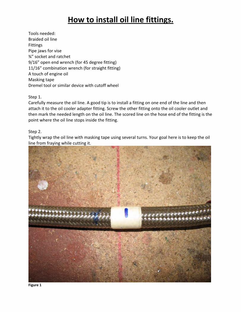
How to install oil line fittings. Tools needed: Braided oil line Fittings Pipe jaws for vise ¾” socket and ratchet 9/16” open end wrench (for 45 degree fitting) 11/16” combination wrench (for straight fitting) A touch of engine oil Masking tape Dremel tool or similar device with cutoff wheel Step 1. Carefully measure the oil line. A good tip is to install a fitting on one end of the line and then attach it to the oil cooler adapter fitting. Screw the other fitting onto the oil cooler outlet and then mark the needed length on the oil line. The scored line on the hose end of the fitting is the point where the oil line stops inside the fitting. Step 2. Tightly wrap the oil line with masking tape using several turns. Your goal here is to keep the oil line from fraying while cutting it.
Figure 1
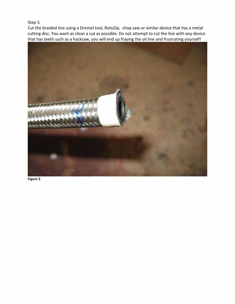
Step 3. Cut the braided line using a Dremel tool, RotoZip, chop saw or similar device that has a metal cutting disc. You want as clean a cut as possible. Do not attempt to cut the line with any device that has teeth such as a hacksaw, you will end up fraying the oil line and frustrating yourself!
Figure 2

Step 4. Remove the tape and insert the oil line vertically in the jaws of the vise.
Figure 3
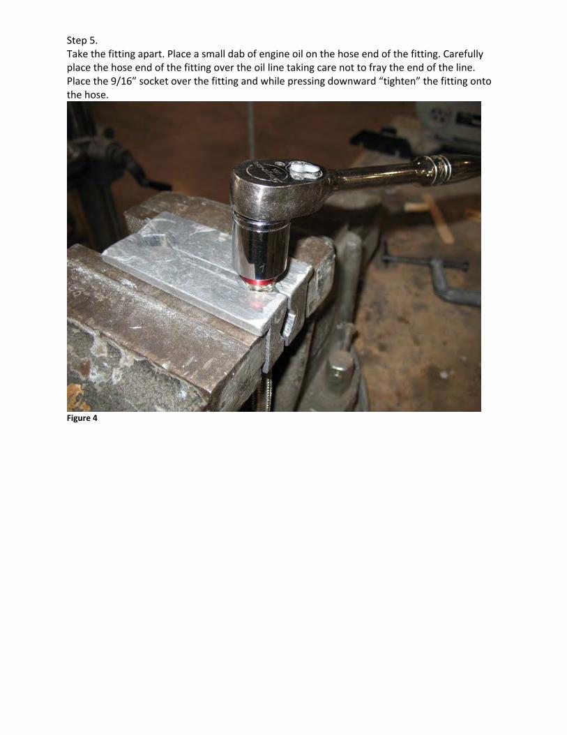
Step 5. Take the fitting apart. Place a small dab of engine oil on the hose end of the fitting. Carefully place the hose end of the fitting over the oil line taking care not to fray the end of the line. Place the 9/16” socket over the fitting and while pressing downward “tighten” the fitting onto the hose.
Figure 4
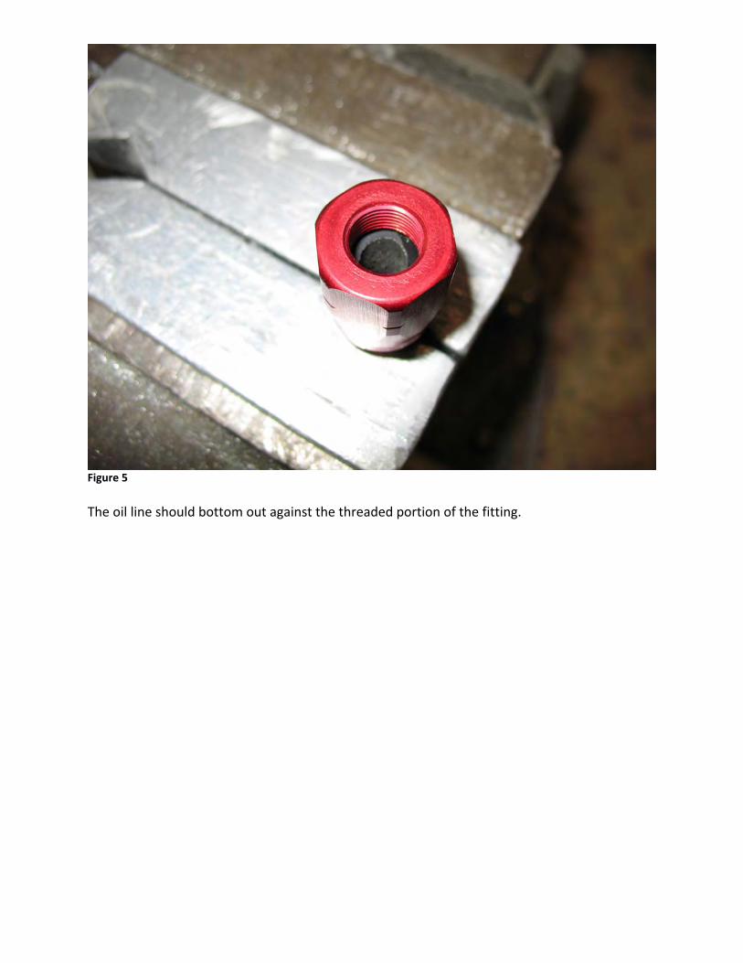
Figure 5 The oil line should bottom out against the threaded portion of the fitting.
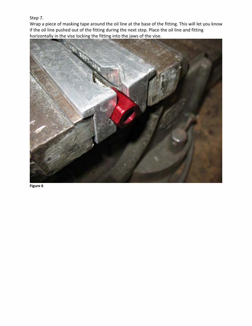
Step 7. Wrap a piece of masking tape around the oil line at the base of the fitting. This will let you know if the oil line pushed out of the fitting during the next step. Place the oil line and fitting horizontally in the vise locking the fitting into the jaws of the vise.
Figure 6
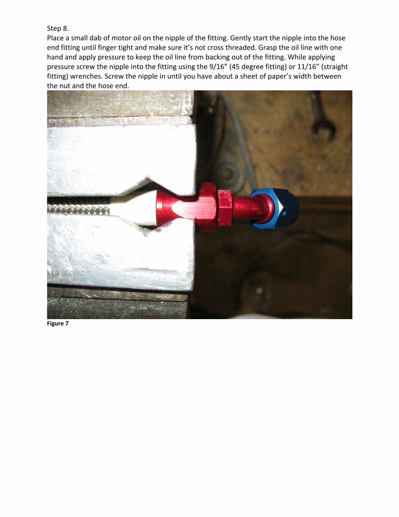
Step 8. Place a small dab of motor oil on the nipple of the fitting. Gently start the nipple into the hose end fitting until finger tight and make sure it’s not cross threaded. Grasp the oil line with one hand and apply pressure to keep the oil line from backing out of the fitting. While applying pressure screw the nipple into the fitting using the 9/16” (45 degree fitting) or 11/16” (straight fitting) wrenches. Screw the nipple in until you have about a sheet of paper’s width between the nut and the hose end.
Figure 7
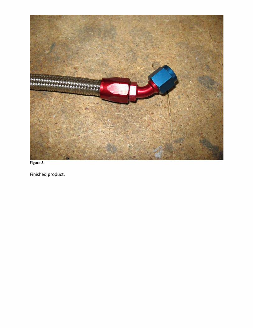
Figure 8 Finished product.
Zenith CH750 FWF Install Manual Jabiru 3300 Engine
Section 1 Fit & Trim Engine Mount Issue A Sept 4, 2009 Page 1 of 2
The engine mount will have to be trimmed so that the mount pads that contact the firewall will fit correctly on the firewall. These five pads have been left over size to allow builders to trim to match their firewall and to allow room to match firewall com-ponents that may have been installed slightly “off” from the standard plans.
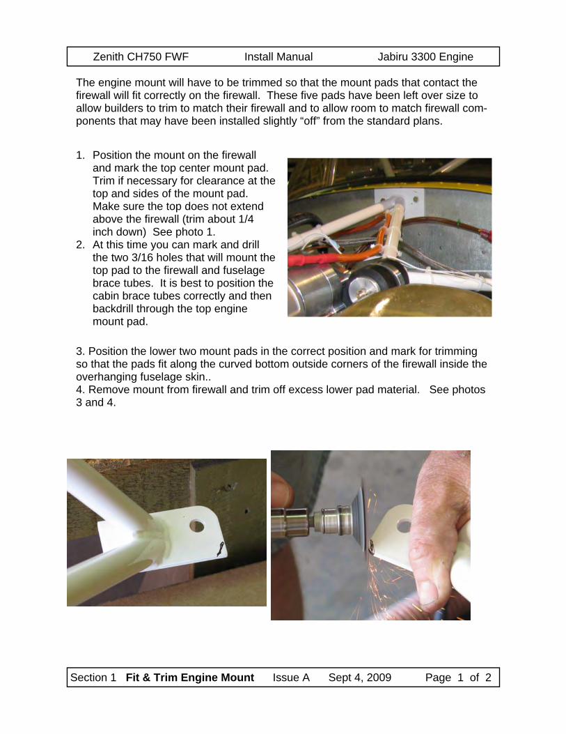
1. Position the mount on the firewall and mark the top center mount pad. Trim if necessary for clearance at the top and sides of the mount pad. Make sure the top does not extend above the firewall (trim about 1/4 inch down) See photo 1.
2. At this time you can mark and drill the two 3/16 holes that will mount the top pad to the firewall and fuselage brace tubes. It is best to position the cabin brace tubes correctly and then backdrill through the top engine mount pad.
3. Position the lower two mount pads in the correct position and mark for trimming so that the pads fit along the curved bottom outside corners of the firewall inside the overhanging fuselage skin.. 4. Remove mount from firewall and trim off excess lower pad material. See photos 3 and 4.
Zenith CH750 FWF Install Manual Jabiru 3300 Engine
Section 1 Fit & Trim Engine Mount Issue A Sept 4, 2009 Page 2 of 2
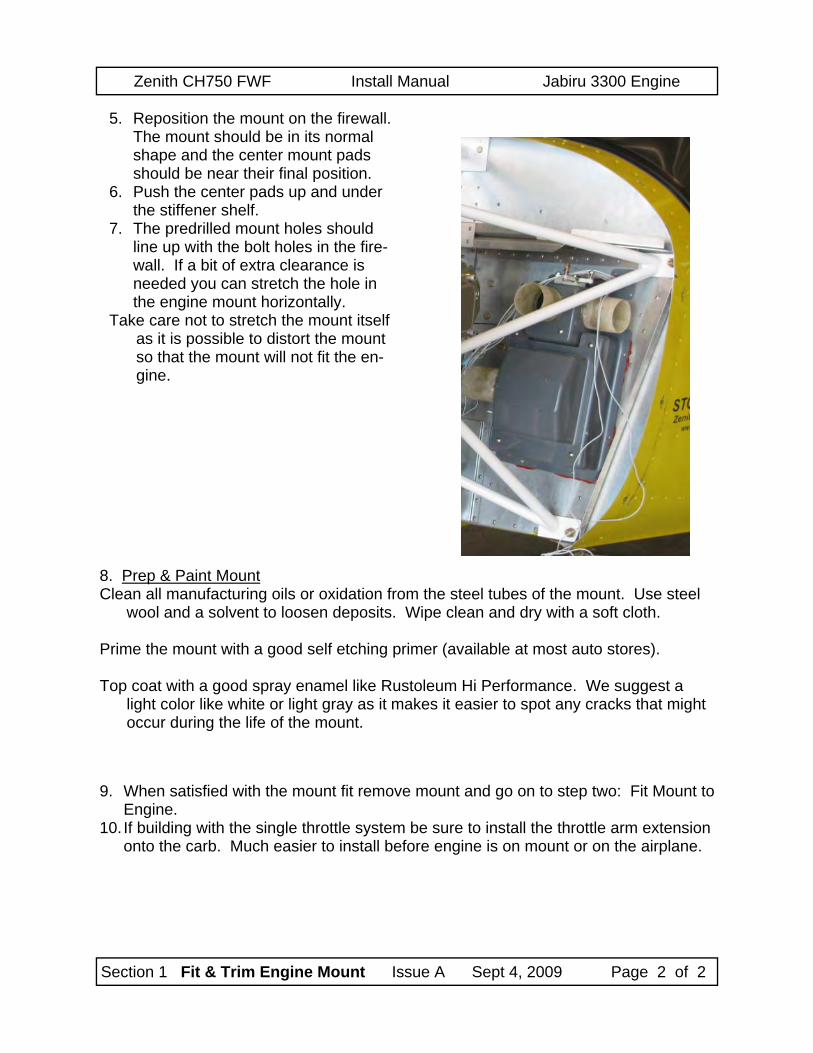
5. Reposition the mount on the firewall. The mount should be in its normal shape and the center mount pads should be near their final position.
6. Push the center pads up and under the stiffener shelf.
7. The predrilled mount holes should line up with the bolt holes in the fire-wall. If a bit of extra clearance is needed you can stretch the hole in the engine mount horizontally.
Take care not to stretch the mount itself as it is possible to distort the mount so that the mount will not fit the en-gine.
9. When satisfied with the mount fit remove mount and go on to step two: Fit Mount to Engine.
10. If building with the single throttle system be sure to install the throttle arm extension onto the carb. Much easier to install before engine is on mount or on the airplane.
8. Prep & Paint Mount Clean all manufacturing oils or oxidation from the steel tubes of the mount. Use steel
wool and a solvent to loosen deposits. Wipe clean and dry with a soft cloth. Prime the mount with a good self etching primer (available at most auto stores). Top coat with a good spray enamel like Rustoleum Hi Performance. We suggest a
light color like white or light gray as it makes it easier to spot any cracks that might occur during the life of the mount.
Zenith CH750 FWF Install Manual Jabiru 3300 Engine
Section 2 Install mount to Engine Issue A January 2011 Page 1 of 3
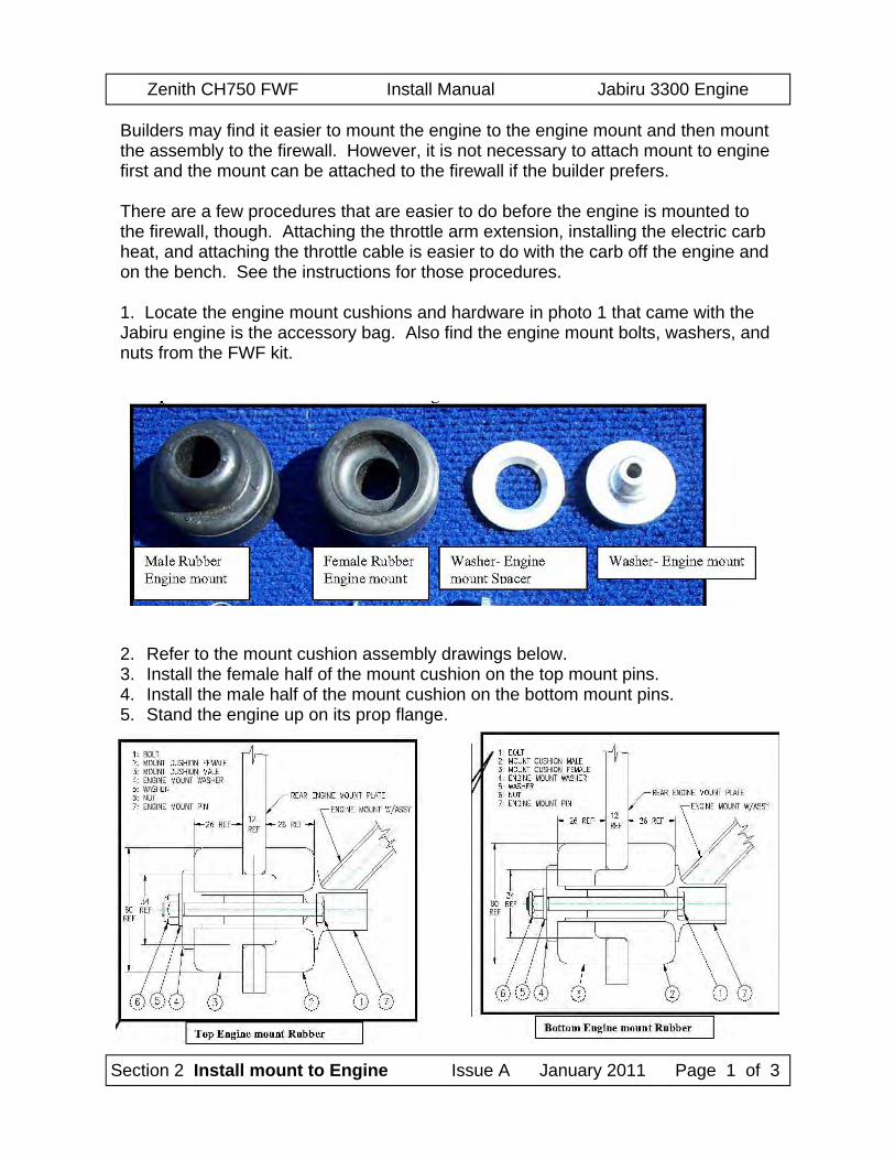
Builders may find it easier to mount the engine to the engine mount and then mount the assembly to the firewall. However, it is not necessary to attach mount to engine first and the mount can be attached to the firewall if the builder prefers. There are a few procedures that are easier to do before the engine is mounted to the firewall, though. Attaching the throttle arm extension, installing the electric carb heat, and attaching the throttle cable is easier to do with the carb off the engine and on the bench. See the instructions for those procedures. 1. Locate the engine mount cushions and hardware in photo 1 that came with the Jabiru engine is the accessory bag. Also find the engine mount bolts, washers, and nuts from the FWF kit.
2. Refer to the mount cushion assembly drawings below. 3. Install the female half of the mount cushion on the top mount pins. 4. Install the male half of the mount cushion on the bottom mount pins. 5. Stand the engine up on its prop flange.
Zenith CH750 FWF Install Manual Jabiru 3300 Engine
Section 2 Install mount to Engine Issue A January 2011 Page 2 of 3
Trim Female Cushion
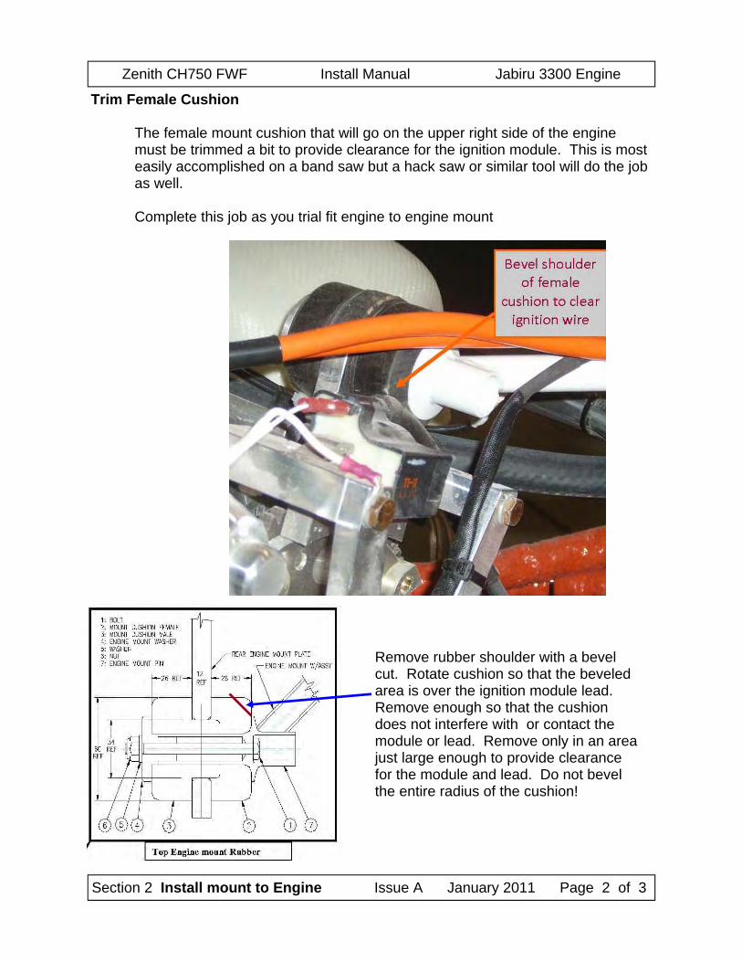
The female mount cushion that will go on the upper right side of the engine must be trimmed a bit to provide clearance for the ignition module. This is most easily accomplished on a band saw but a hack saw or similar tool will do the job as well. Complete this job as you trial fit engine to engine mount
Remove rubber shoulder with a bevel cut. Rotate cushion so that the beveled area is over the ignition module lead. Remove enough so that the cushion does not interfere with or contact the module or lead. Remove only in an area just large enough to provide clearance for the module and lead. Do not bevel the entire radius of the cushion!
Zenith CH750 FWF Install Manual Jabiru 3300 Engine
Section 2 Install mount to Engine Issue A January 2011 Page 3 of 3
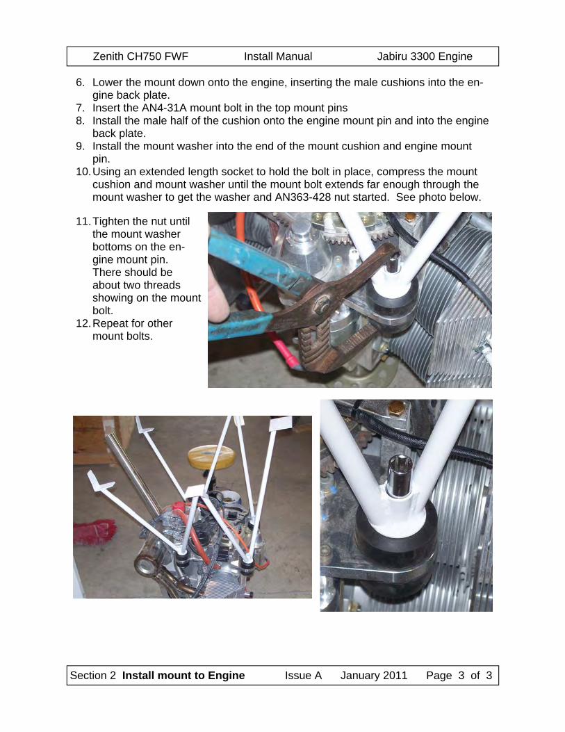
6. Lower the mount down onto the engine, inserting the male cushions into the en-gine back plate.
7. Insert the AN4-31A mount bolt in the top mount pins 8. Install the male half of the cushion onto the engine mount pin and into the engine
back plate. 9. Install the mount washer into the end of the mount cushion and engine mount
pin. 10. Using an extended length socket to hold the bolt in place, compress the mount
cushion and mount washer until the mount bolt extends far enough through the mount washer to get the washer and AN363-428 nut started. See photo below.
11. Tighten the nut until the mount washer bottoms on the en-gine mount pin. There should be about two threads showing on the mount bolt.
12. Repeat for other mount bolts.
Zenith CH750 FWF Install Manual Jabiru 3300 Engine
Section 3 Install Mount & Engine to Firewall Issue A January, 2011 Page 1 of 3
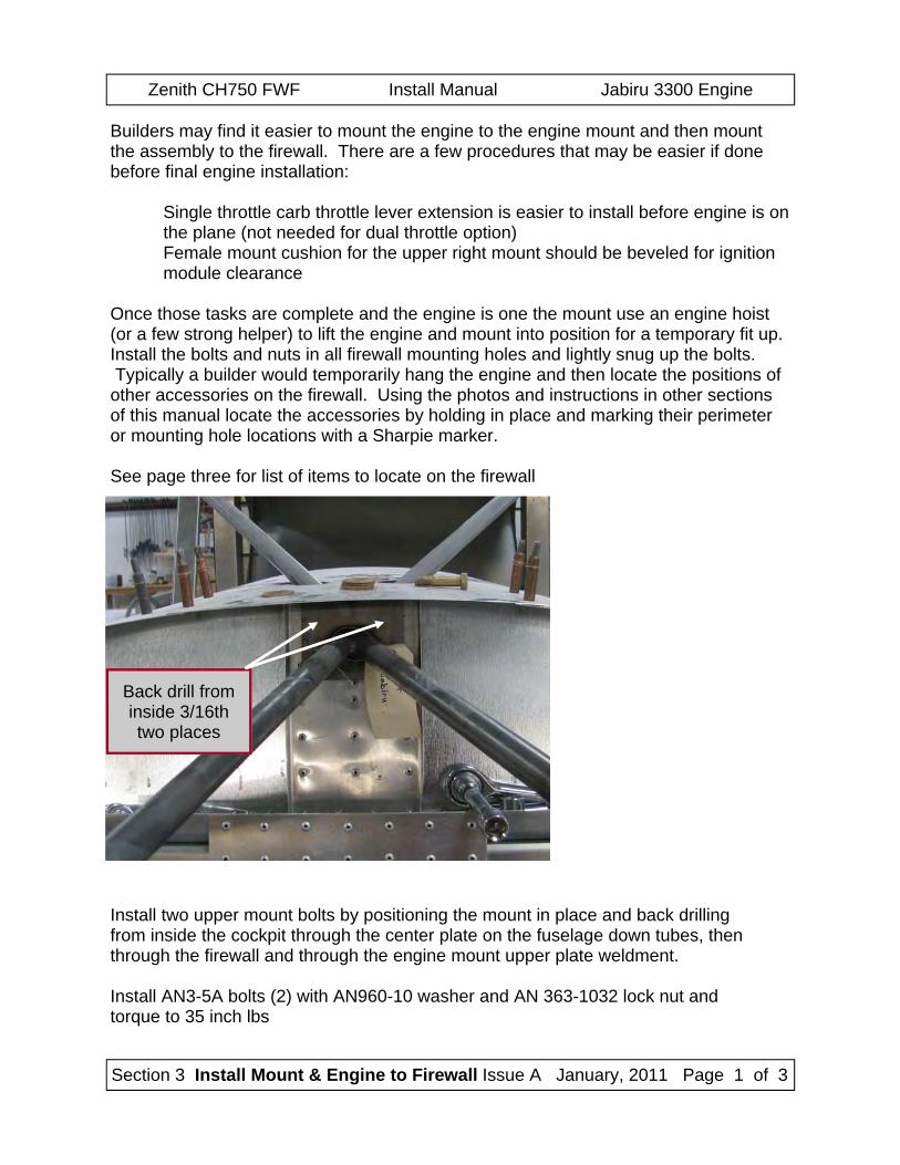
Builders may find it easier to mount the engine to the engine mount and then mount the assembly to the firewall. There are a few procedures that may be easier if done before final engine installation:
Single throttle carb throttle lever extension is easier to install before engine is on the plane (not needed for dual throttle option) Female mount cushion for the upper right mount should be beveled for ignition module clearance
Once those tasks are complete and the engine is one the mount use an engine hoist (or a few strong helper) to lift the engine and mount into position for a temporary fit up. Install the bolts and nuts in all firewall mounting holes and lightly snug up the bolts. Typically a builder would temporarily hang the engine and then locate the positions of other accessories on the firewall. Using the photos and instructions in other sections of this manual locate the accessories by holding in place and marking their perimeter or mounting hole locations with a Sharpie marker. See page three for list of items to locate on the firewall
Install two upper mount bolts by positioning the mount in place and back drilling from inside the cockpit through the center plate on the fuselage down tubes, then through the firewall and through the engine mount upper plate weldment. Install AN3-5A bolts (2) with AN960-10 washer and AN 363-1032 lock nut and torque to 35 inch lbs
Back drill from inside 3/16th two places
Zenith CH750 FWF Install Manual Jabiru 3300 Engine
Section 3 Install Mount & Engine to Firewall Issue A January, 2011 Page 2 of 3
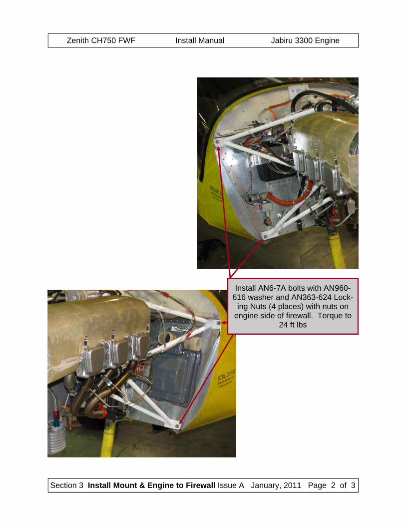
Install AN6-7A bolts with AN960-616 washer and AN363-624 Lock-
ing Nuts (4 places) with nuts on engine side of firewall. Torque to
24 ft lbs
Zenith CH750 FWF Install Manual Jabiru 3300 Engine
Section 3 Install Mount & Engine to Firewall Issue A January, 2011 Page 3 of 3
Airbox Place the carb heat air filter / mixer box on the firewall on the left side of the air-
craft below the shelf on the firewall. Try to position the box so that the outlet to the carb is as closely lined up to the carb inlet as possible. The less down or up angle in the SCAT duct from airbox to carb inlet the bet-ter.
Check to see that there is clearance under the firewall stiffener shelf for the cam to operate freely and for the cable to attach to the cam.
Mark the outline of the airbox with a felt tip marker. Cabin Heat Mixer Box (optional)
If installing cabin heat locate the mixer box close to the center of the aircraft to the right side of the nose leg channel.
Mark the location with your marker Battery Support & Clamp
Locate the battery on the right side of the firewall under the stiffener shelf. Keep it as high as you can to allow more room for other firewall items to be in-stalled later. Also – keep the battery as far toward the outside of the air-craft as possible to allow as much room for other components as you can.
Mark the outline of the battery Oil Recovery Bottle
Locate the Oil Recovery Bottle in an open space on the right side of the firewall where it does not conflict with cabin heat or battery.
The bottle does not have to be vertical but can be slanted to help with the fit. Mark the outline of the bottle.
Fuel fitting Fuel should pass through the firewall on the right side. Hose will run from the
firewall to the pump mounted on the right rear side of the engine. Locate the fuel fitting on the firewall where it wil not conflict with other firewall
mounted items. Mark the location.
Starter Solenoid Since the battery is on the right side of the aircraft and the starter cable comes
back quite naturally toward the right side of the engine, it is natural to lo-cate the solenoid close to the battery on the firewall stiffener shelf.
Regulator Locate the regulator on the shelf as well near the battery. Make sure that sole-
noid and regulator are located so as not to interfere with the dual throttle cross rod if dual throttles are being installed.
After firewall items are located it may be easier to remove engine to permanently install those items that are on the firewall. Final engine installation then is accomplished by installing all bolts and tightening to the appropriate torque for aircraft AN bolts.
Zenith CH750 FWF Install Manual Jabiru 3300 Engine
Section 4 Install Air Filter Box Issue A January, 2011 Page 1 of 3
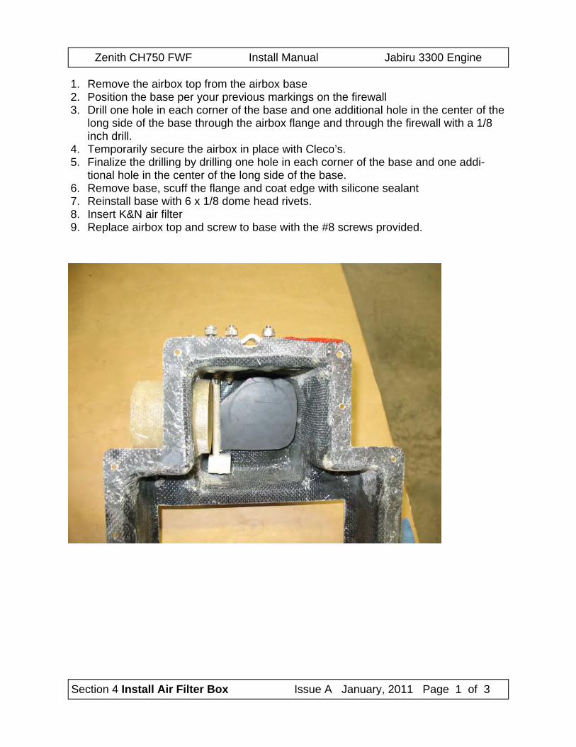
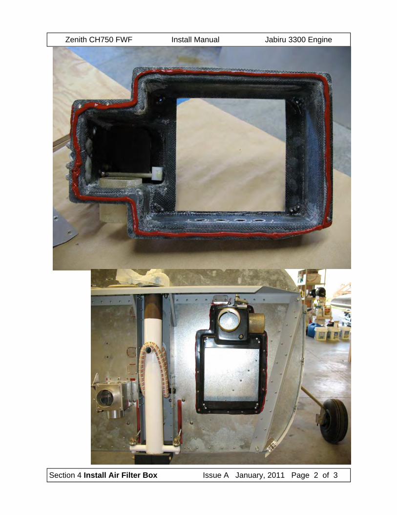
1. Remove the airbox top from the airbox base 2. Position the base per your previous markings on the firewall 3. Drill one hole in each corner of the base and one additional hole in the center of the
long side of the base through the airbox flange and through the firewall with a 1/8 inch drill.
4. Temporarily secure the airbox in place with Cleco’s. 5. Finalize the drilling by drilling one hole in each corner of the base and one addi-
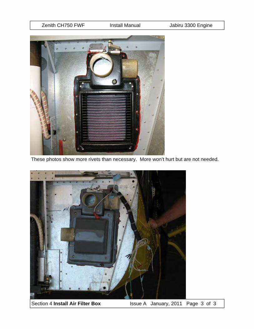
tional hole in the center of the long side of the base. 6. Remove base, scuff the flange and coat edge with silicone sealant 7. Reinstall base with 6 x 1/8 dome head rivets. 8. Insert K&N air filter 9. Replace airbox top and screw to base with the #8 screws provided.
Zenith CH750 FWF Install Manual Jabiru 3300 Engine
Section 4 Install Air Filter Box Issue A January, 2011 Page 2 of 3
Zenith CH750 FWF Install Manual Jabiru 3300 Engine
Section 4 Install Air Filter Box Issue A January, 2011 Page 3 of 3
These photos show more rivets than necessary. More won’t hurt but are not needed.
Zenith CH750 FWF Install Manual Jabiru 3300 Engine
Section 5 Install Cabin Heat Box Issue A January, 2011 Page 1 of 3
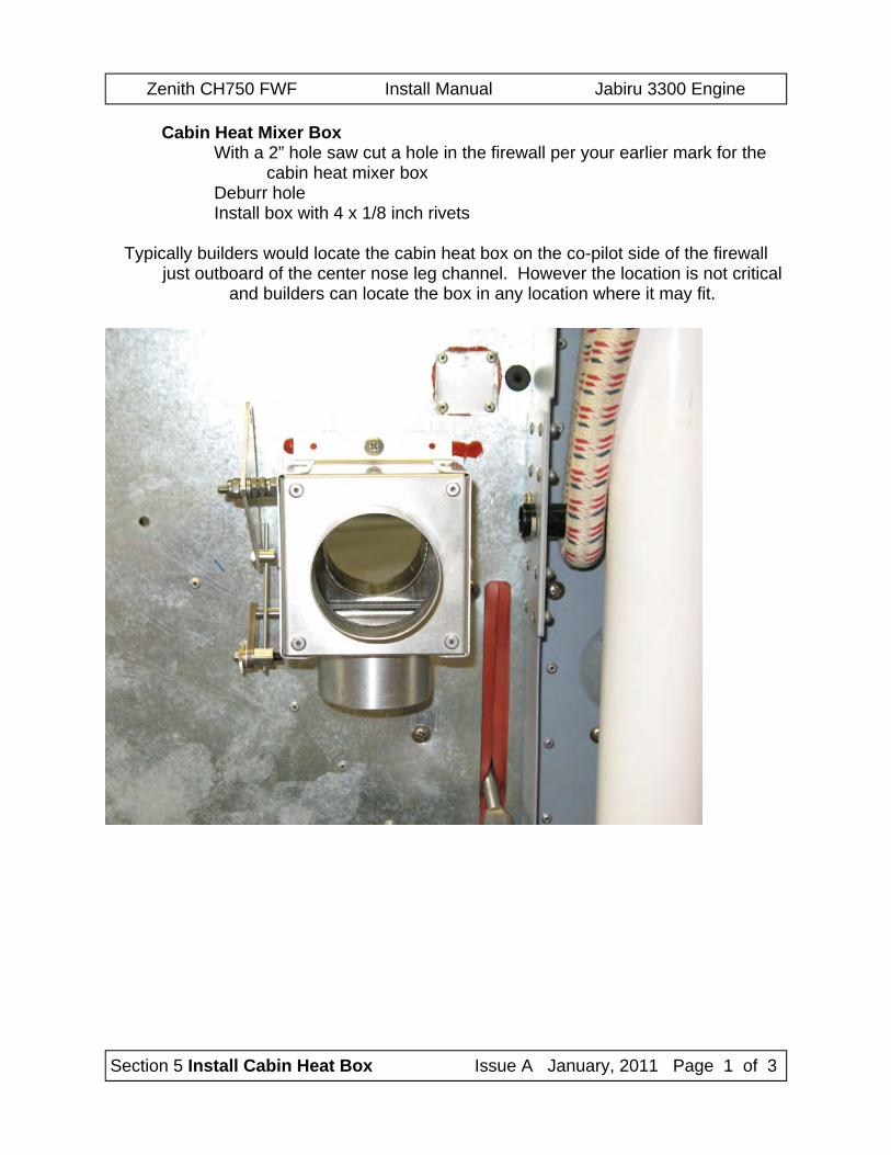
Cabin Heat Mixer Box With a 2” hole saw cut a hole in the firewall per your earlier mark for the
cabin heat mixer box Deburr hole Install box with 4 x 1/8 inch rivets
Typically builders would locate the cabin heat box on the co-pilot side of the firewall just outboard of the center nose leg channel. However the location is not critical
and builders can locate the box in any location where it may fit.
Zenith CH750 FWF Install Manual Jabiru 3300 Engine
Section 5 Install Cabin Heat Box Issue A January, 2011 Page 2 of 3
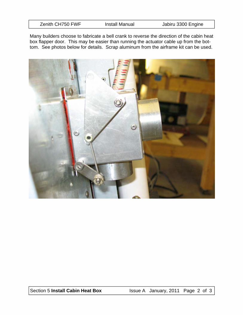
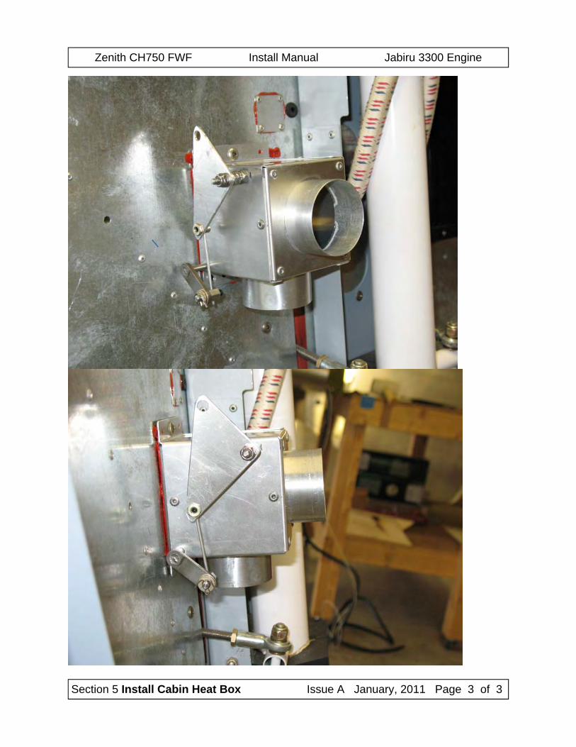
Many builders choose to fabricate a bell crank to reverse the direction of the cabin heat box flapper door. This may be easier than running the actuator cable up from the bot-tom. See photos below for details. Scrap aluminum from the airframe kit can be used.
Zenith CH750 FWF Install Manual Jabiru 3300 Engine
Section 5 Install Cabin Heat Box Issue A January, 2011 Page 3 of 3
Zenith CH750 FWF Install Manual Jabiru 3300 Engine
Section 6 Battery Support & Clamp Issue A January, 2011 Page 1 of 3
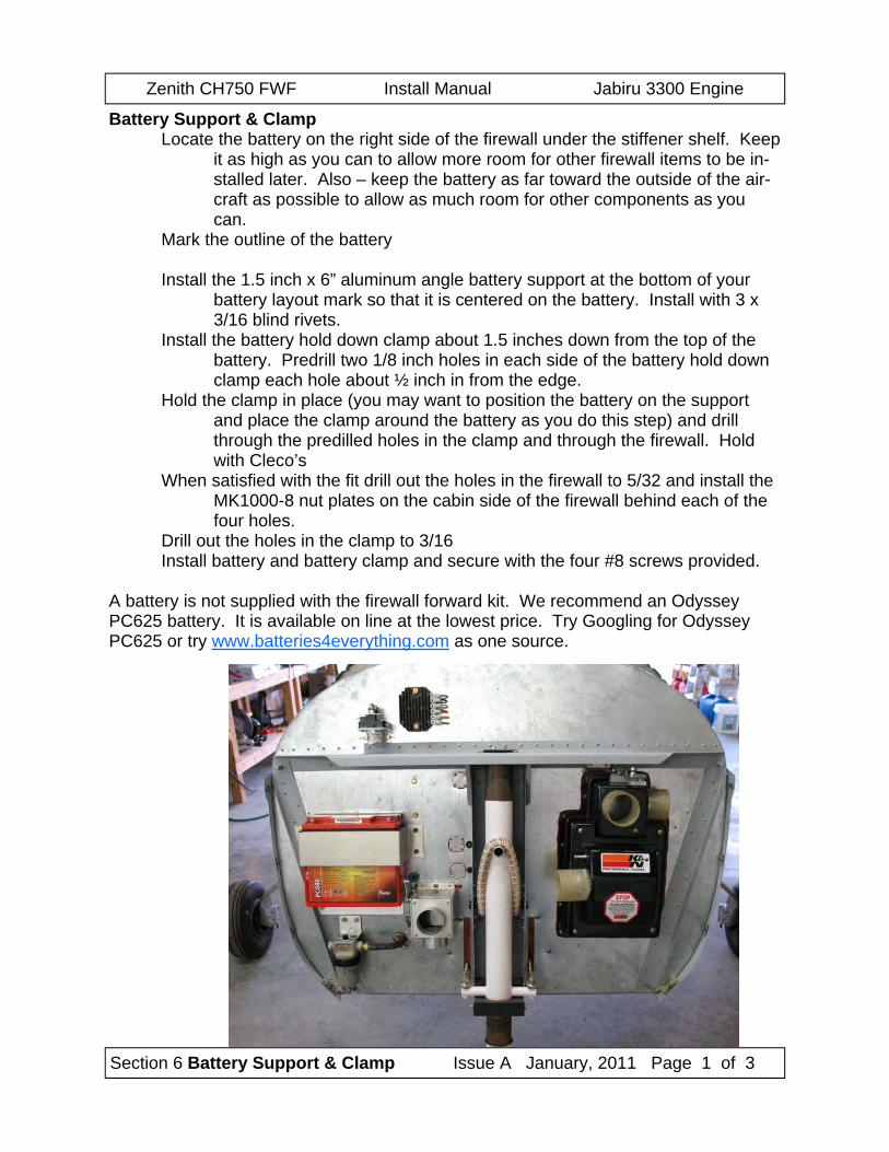
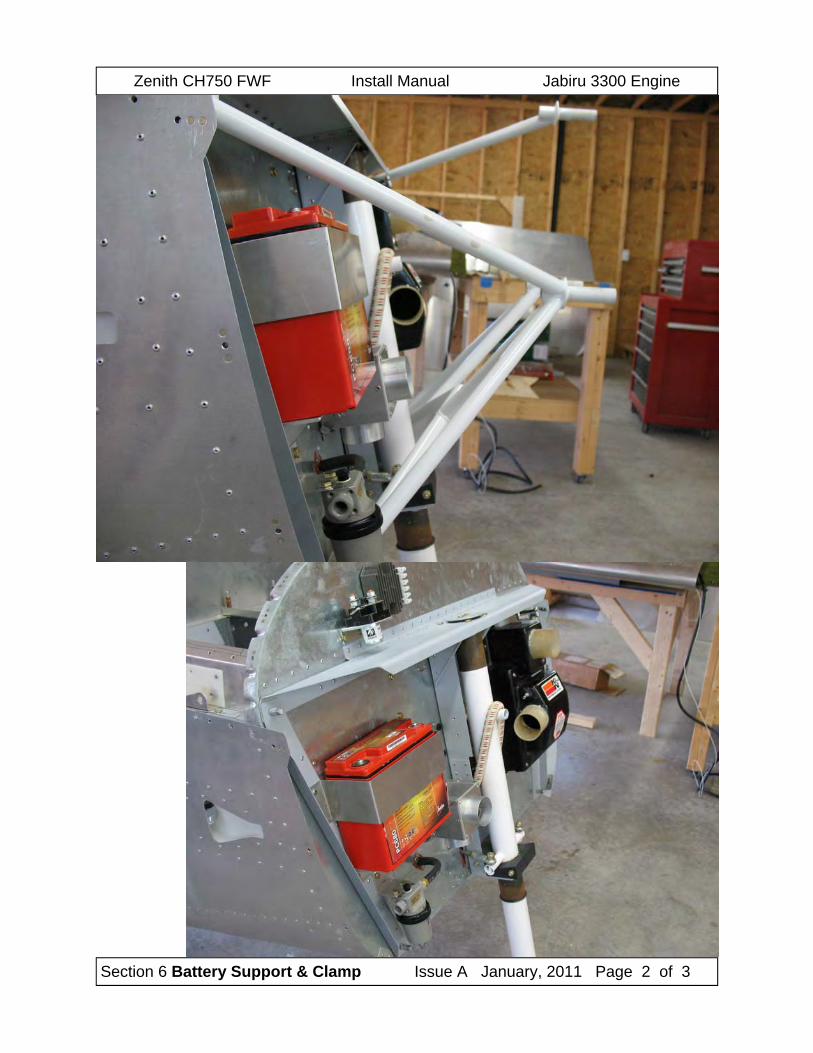
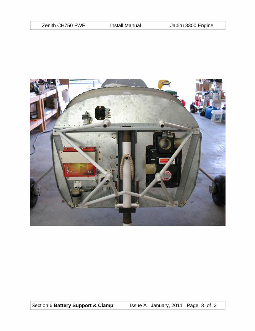
Battery Support & Clamp Locate the battery on the right side of the firewall under the stiffener shelf. Keep
it as high as you can to allow more room for other firewall items to be in-stalled later. Also – keep the battery as far toward the outside of the air-craft as possible to allow as much room for other components as you can.
Mark the outline of the battery Install the 1.5 inch x 6” aluminum angle battery support at the bottom of your
battery layout mark so that it is centered on the battery. Install with 3 x 3/16 blind rivets.
Install the battery hold down clamp about 1.5 inches down from the top of the battery. Predrill two 1/8 inch holes in each side of the battery hold down clamp each hole about ½ inch in from the edge.
Hold the clamp in place (you may want to position the battery on the support and place the clamp around the battery as you do this step) and drill through the predilled holes in the clamp and through the firewall. Hold with Cleco’s
When satisfied with the fit drill out the holes in the firewall to 5/32 and install the MK1000-8 nut plates on the cabin side of the firewall behind each of the four holes.
Drill out the holes in the clamp to 3/16 Install battery and battery clamp and secure with the four #8 screws provided.
A battery is not supplied with the firewall forward kit. We recommend an Odyssey PC625 battery. It is available on line at the lowest price. Try Googling for Odyssey PC625 or try www.batteries4everything.com as one source.
Zenith CH750 FWF Install Manual Jabiru 3300 Engine
Section 6 Battery Support & Clamp Issue A January, 2011 Page 2 of 3
Zenith CH750 FWF Install Manual Jabiru 3300 Engine
Section 6 Battery Support & Clamp Issue A January, 2011 Page 3 of 3
Zenith CH750 FWF Install Manual Jabiru 3300 Engine
Section 7 Oil Recovery Bottle Issue A January, 2011 Page 1 of 1
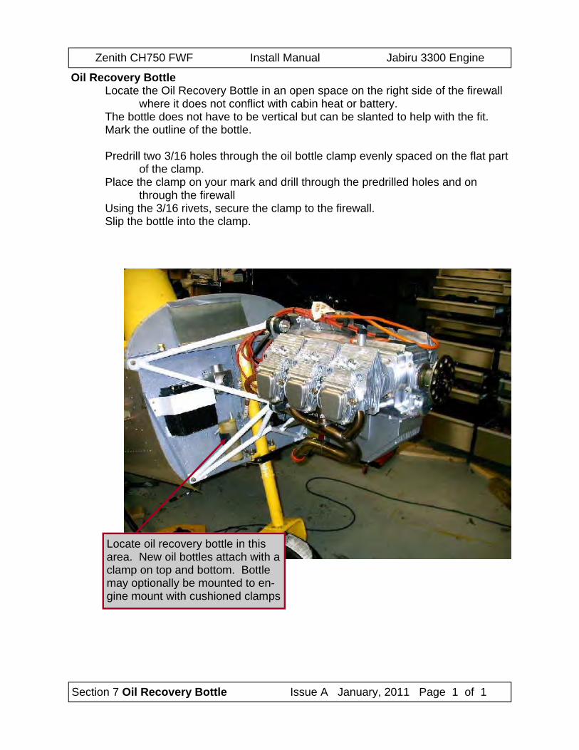
Oil Recovery Bottle Locate the Oil Recovery Bottle in an open space on the right side of the firewall
where it does not conflict with cabin heat or battery. The bottle does not have to be vertical but can be slanted to help with the fit. Mark the outline of the bottle. Predrill two 3/16 holes through the oil bottle clamp evenly spaced on the flat part
of the clamp. Place the clamp on your mark and drill through the predrilled holes and on
through the firewall Using the 3/16 rivets, secure the clamp to the firewall. Slip the bottle into the clamp.
Locate oil recovery bottle in this area. New oil bottles attach with a clamp on top and bottom. Bottle may optionally be mounted to en-gine mount with cushioned clamps
Zenith CH750 FWF Install Manual Jabiru 3300 Engine
Section 8 Fuel System FWF Issue A January 2011 Page 1 of 3
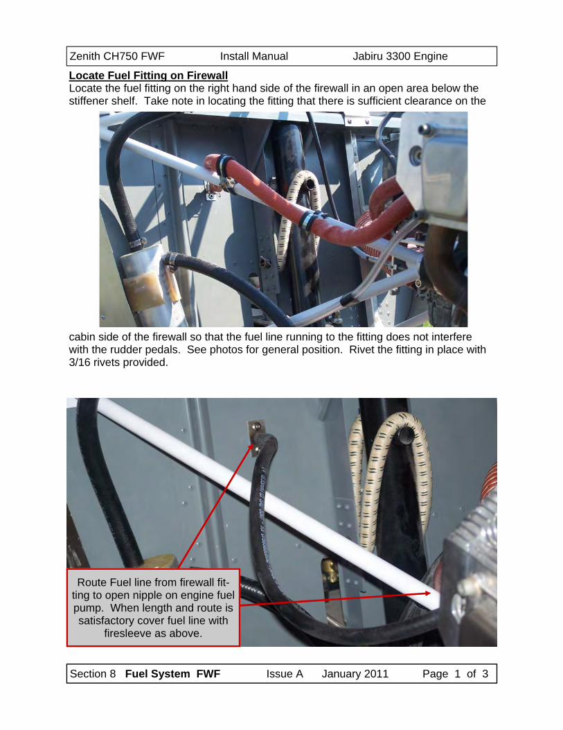
Locate Fuel Fitting on Firewall Locate the fuel fitting on the right hand side of the firewall in an open area below the stiffener shelf. Take note in locating the fitting that there is sufficient clearance on the
cabin side of the firewall so that the fuel line running to the fitting does not interfere with the rudder pedals. See photos for general position. Rivet the fitting in place with 3/16 rivets provided.
Route Fuel line from firewall fit-ting to open nipple on engine fuel pump. When length and route is satisfactory cover fuel line with
firesleeve as above.
Zenith CH750 FWF Install Manual Jabiru 3300 Engine
Section 8 Fuel System FWF Issue A January 2011 Page 2 of 3
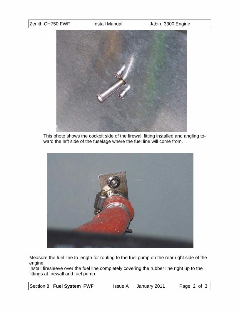
This photo shows the cockpit side of the firewall fitting installed and angling to-ward the left side of the fuselage where the fuel line will come from.
Measure the fuel line to length for routing to the fuel pump on the rear right side of the engine. Install firesleeve over the fuel line completely covering the rubber line right up to the fittings at firewall and fuel pump.
Zenith CH750 FWF Install Manual Jabiru 3300 Engine
Section 8 Fuel System FWF Issue A January 2011 Page 3 of 3
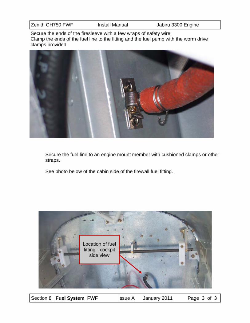
Secure the fuel line to an engine mount member with cushioned clamps or other straps. See photo below of the cabin side of the firewall fuel fitting.
Secure the ends of the firesleeve with a few wraps of safety wire. Clamp the ends of the fuel line to the fitting and the fuel pump with the worm drive clamps provided.
Location of fuel fitting - cockpit
side view
Zenith CH750 FWF Install Manual Jabiru 3300 Engine
Section 9 Regulator & Solenoid Issue A January 2011 Page 1 of 4
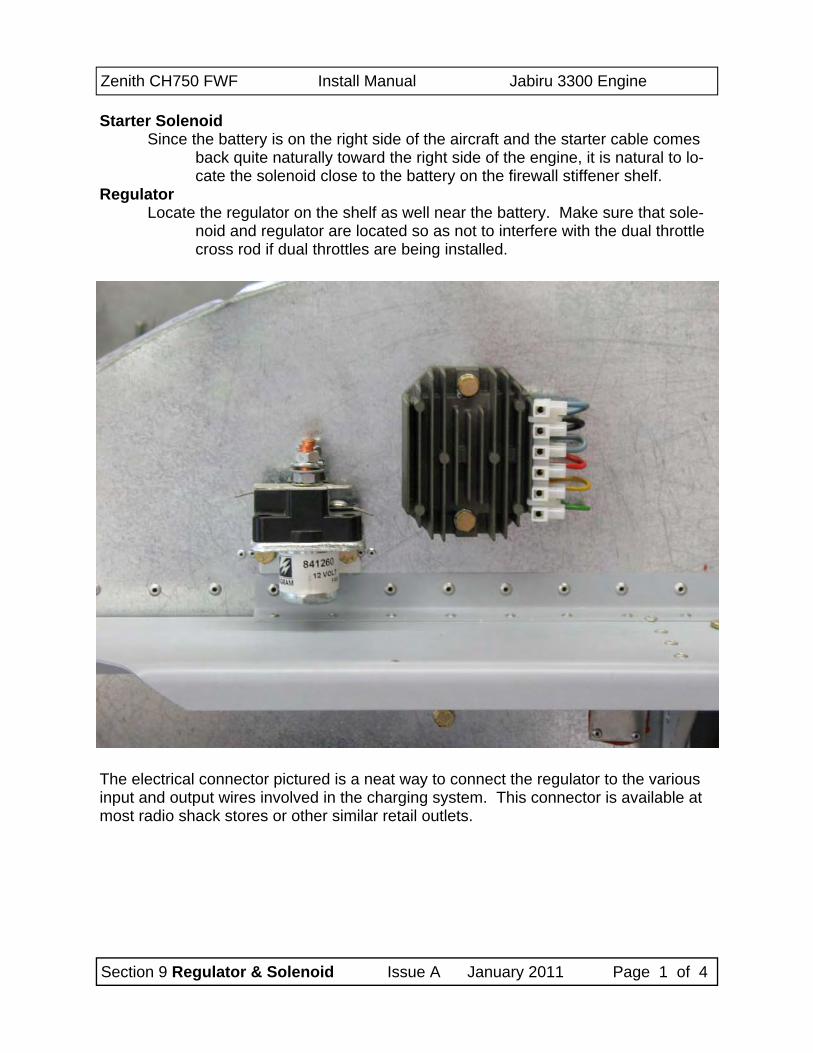
Starter Solenoid Since the battery is on the right side of the aircraft and the starter cable comes
back quite naturally toward the right side of the engine, it is natural to lo-cate the solenoid close to the battery on the firewall stiffener shelf.
Regulator Locate the regulator on the shelf as well near the battery. Make sure that sole-
noid and regulator are located so as not to interfere with the dual throttle cross rod if dual throttles are being installed.
The electrical connector pictured is a neat way to connect the regulator to the various input and output wires involved in the charging system. This connector is available at most radio shack stores or other similar retail outlets.
Zenith CH750 FWF Install Manual Jabiru 3300 Engine
Section 9 Regulator & Solenoid Issue A January 2011 Page 2 of 4
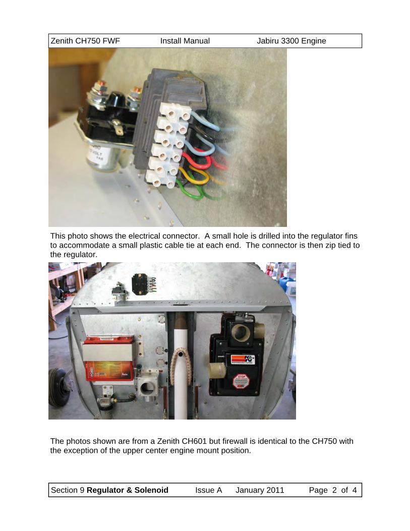
This photo shows the electrical connector. A small hole is drilled into the regulator fins to accommodate a small plastic cable tie at each end. The connector is then zip tied to the regulator.
The photos shown are from a Zenith CH601 but firewall is identical to the CH750 with the exception of the upper center engine mount position.
Zenith CH750 FWF Install Manual Jabiru 3300 Engine
Section 9 Regulator & Solenoid Issue A January 2011 Page 3 of 4
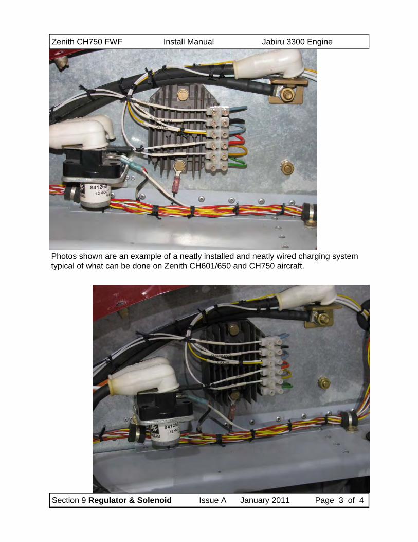
Photos shown are an example of a neatly installed and neatly wired charging system typical of what can be done on Zenith CH601/650 and CH750 aircraft.
Zenith CH750 FWF Install Manual Jabiru 3300 Engine
Section 9 Regulator & Solenoid Issue A January 2011 Page 4 of 4
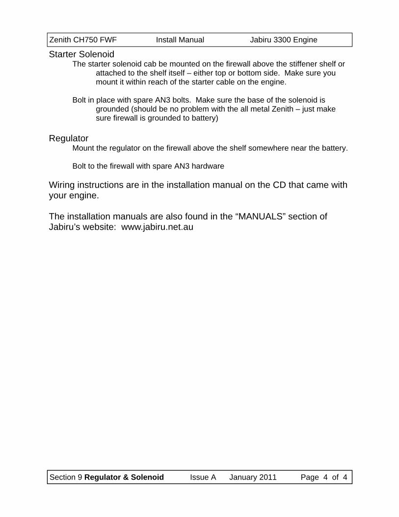
Starter Solenoid The starter solenoid cab be mounted on the firewall above the stiffener shelf or
attached to the shelf itself – either top or bottom side. Make sure you mount it within reach of the starter cable on the engine.
Bolt in place with spare AN3 bolts. Make sure the base of the solenoid is
grounded (should be no problem with the all metal Zenith – just make sure firewall is grounded to battery)
Regulator
Mount the regulator on the firewall above the shelf somewhere near the battery. Bolt to the firewall with spare AN3 hardware
Wiring instructions are in the installation manual on the CD that came with your engine. The installation manuals are also found in the “MANUALS” section of Jabiru’s website: www.jabiru.net.au
Zenith CH750 FWF Install Manual Jabiru 3300 Engine
Section 10 Ramair Cooling Duct Issue A January 2011 Page 1 of 5
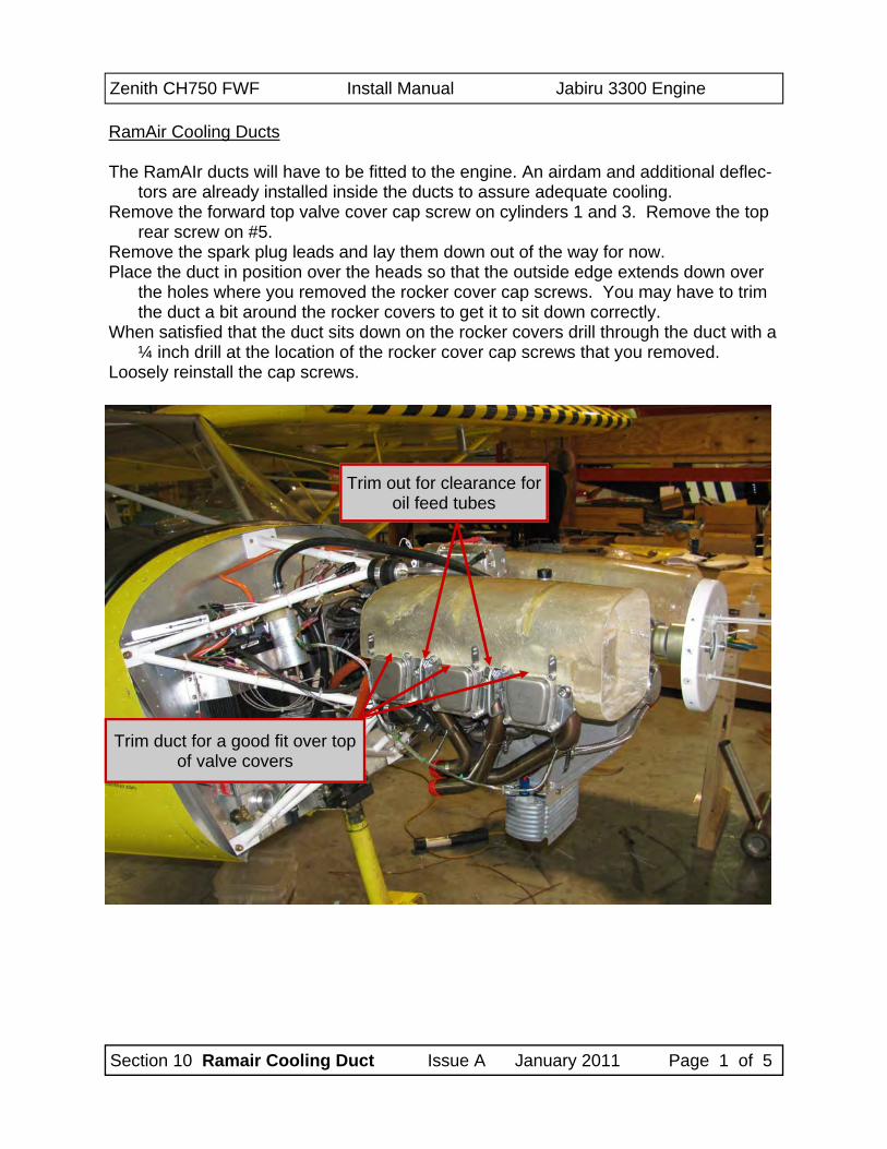
RamAir Cooling Ducts The RamAIr ducts will have to be fitted to the engine. An airdam and additional deflec-
tors are already installed inside the ducts to assure adequate cooling. Remove the forward top valve cover cap screw on cylinders 1 and 3. Remove the top
rear screw on #5. Remove the spark plug leads and lay them down out of the way for now. Place the duct in position over the heads so that the outside edge extends down over
the holes where you removed the rocker cover cap screws. You may have to trim the duct a bit around the rocker covers to get it to sit down correctly.
When satisfied that the duct sits down on the rocker covers drill through the duct with a ¼ inch drill at the location of the rocker cover cap screws that you removed.
Loosely reinstall the cap screws.
Trim duct for a good fit over top of valve covers
Trim out for clearance for oil feed tubes
Zenith CH750 FWF Install Manual Jabiru 3300 Engine
Section 10 Ramair Cooling Duct Issue A January 2011 Page 2 of 5
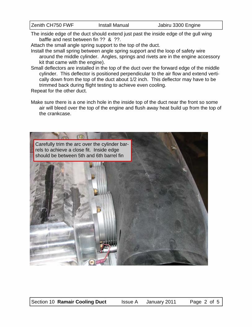
The inside edge of the duct should extend just past the inside edge of the gull wing baffle and nest between fin ?? & ??.
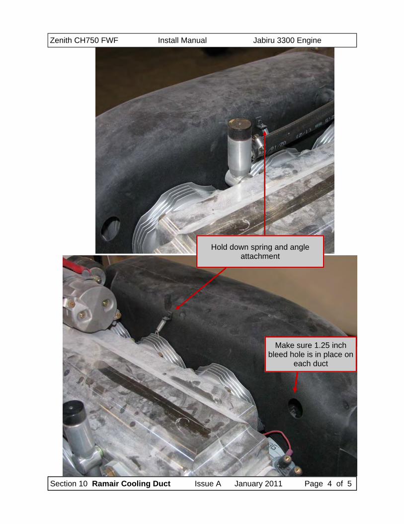
Attach the small angle spring support to the top of the duct. Install the small spring between angle spring support and the loop of safety wire
around the middle cylinder. Angles, springs and rivets are in the engine accessory kit that came with the engine).
Small deflectors are installed in the top of the duct over the forward edge of the middle cylinder. This deflector is positioned perpendicular to the air flow and extend verti-cally down from the top of the duct about 1/2 inch. This deflector may have to be trimmed back during flight testing to achieve even cooling.
Repeat for the other duct. Make sure there is a one inch hole in the inside top of the duct near the front so some
air will bleed over the top of the engine and flush away heat build up from the top of the crankcase.
Carefully trim the arc over the cylinder bar-rels to achieve a close fit. Inside edge should be between 5th and 6th barrel fin
Zenith CH750 FWF Install Manual Jabiru 3300 Engine
Section 10 Ramair Cooling Duct Issue A January 2011 Page 3 of 5
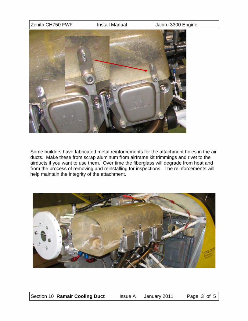
Some builders have fabricated metal reinforcements for the attachment holes in the air ducts. Make these from scrap aluminum from airframe kit trimmings and rivet to the airducts if you want to use them. Over time the fiberglass will degrade from heat and from the process of removing and reinstalling for inspections. The reinforcements will help maintain the integrity of the attachment.
Zenith CH750 FWF Install Manual Jabiru 3300 Engine
Section 10 Ramair Cooling Duct Issue A January 2011 Page 4 of 5
Hold down spring and angle attachment
Make sure 1.25 inch bleed hole is in place on
each duct
Zenith CH750 FWF Install Manual Jabiru 3300 Engine
Section 10 Ramair Cooling Duct Issue A January 2011 Page 5 of 5
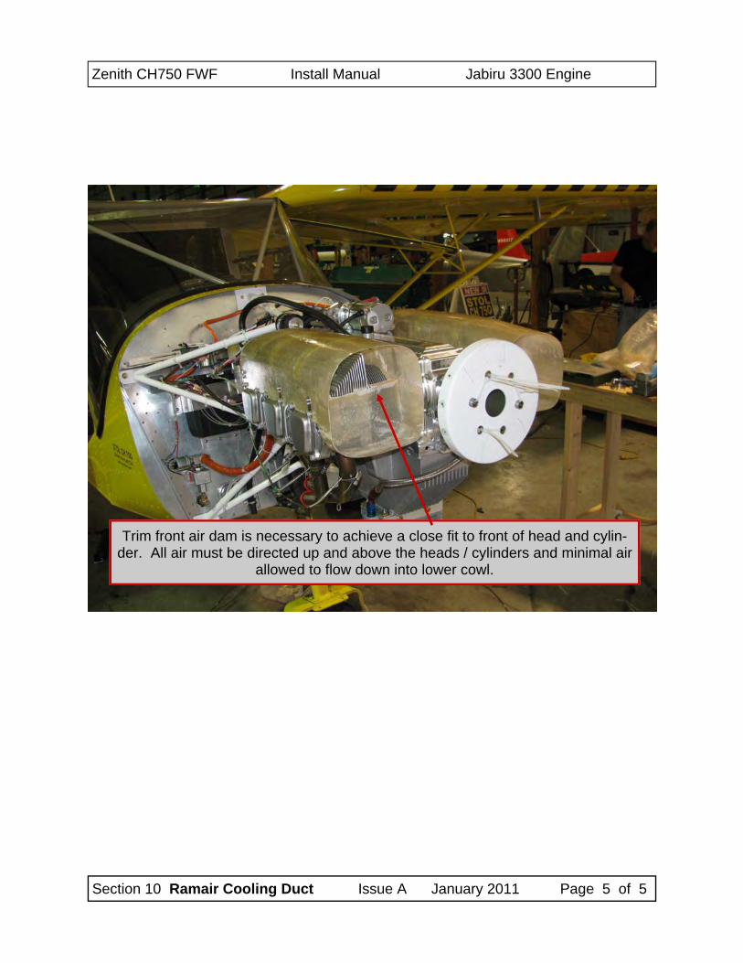
Trim front air dam is necessary to achieve a close fit to front of head and cylin-der. All air must be directed up and above the heads / cylinders and minimal air
allowed to flow down into lower cowl.
Vans RV-12 Install Manual Jabiru 2200 Engine
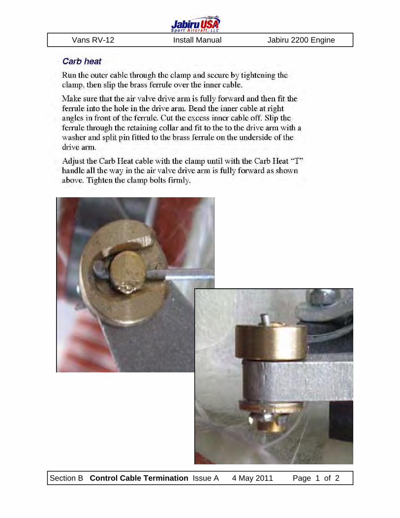
Section B Control Cable Termination Issue A 4 May 2011 Page 1 of 2
Vans RV-12 Install Manual Jabiru 2200 Engine
Section B Control Cable Termination Issue A 4 May 2011 Page 2 of 2
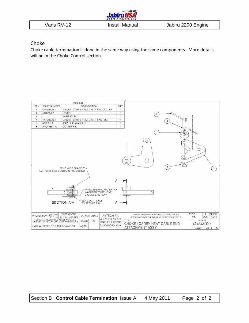
Choke Choke cable termination is done in the same way using the same components. More details will be in the Choke Control section.
Zenith CH750 FWF Install Manual Jabiru 3300 Engine
Section 12 Choke Install Issue A January 2011 Page 1 of 4
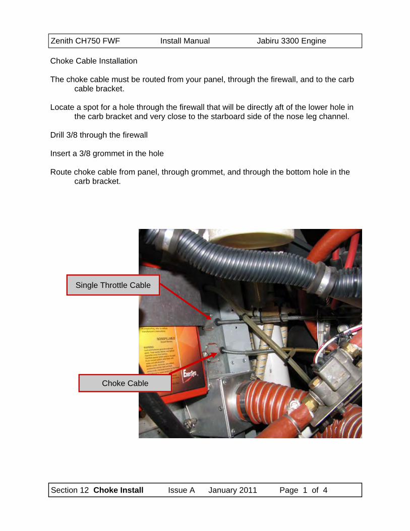
Choke Cable Installation The choke cable must be routed from your panel, through the firewall, and to the carb
cable bracket. Locate a spot for a hole through the firewall that will be directly aft of the lower hole in
the carb bracket and very close to the starboard side of the nose leg channel. Drill 3/8 through the firewall Insert a 3/8 grommet in the hole Route choke cable from panel, through grommet, and through the bottom hole in the
carb bracket.
Choke Cable
Single Throttle Cable
Zenith CH750 FWF Install Manual Jabiru 3300 Engine
Section 12 Choke Install Issue A January 2011 Page 2 of 4
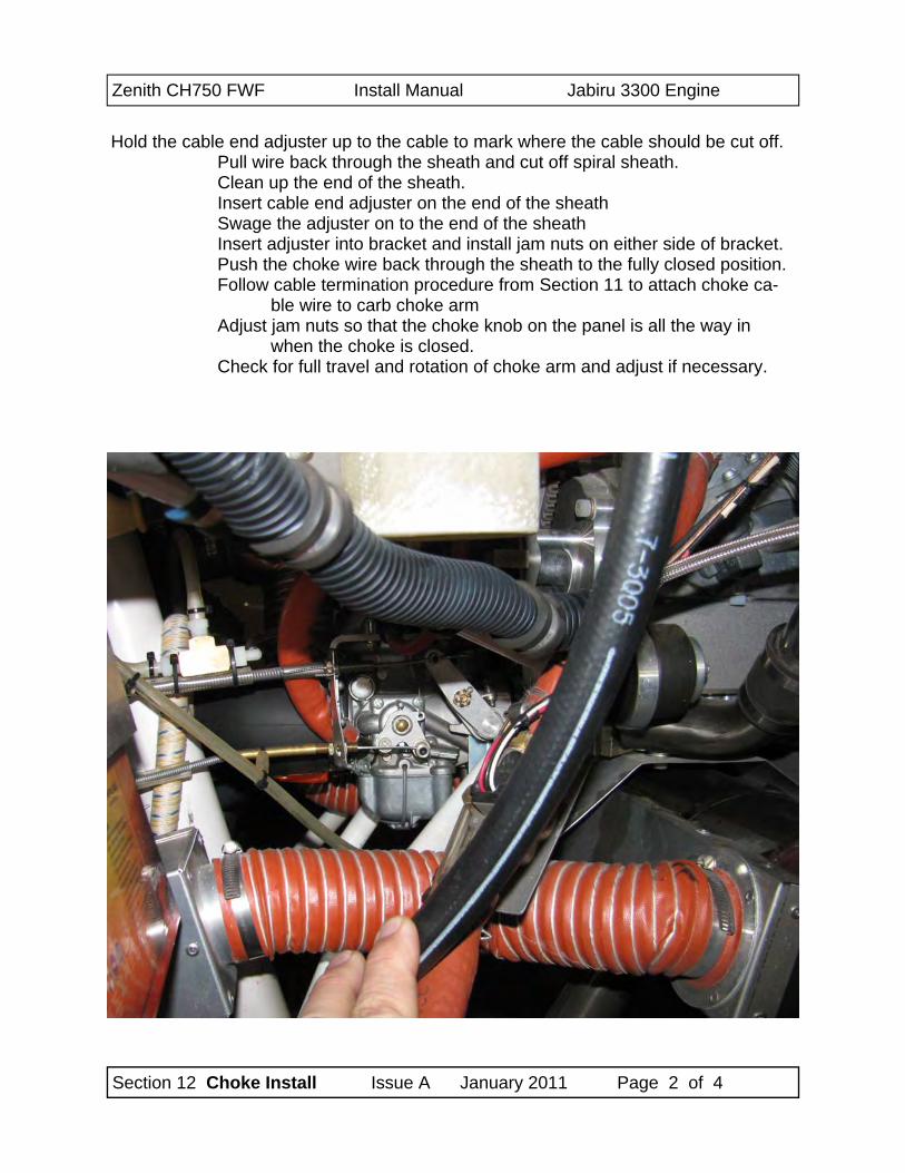
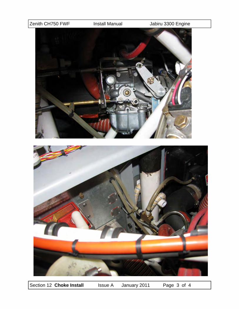
Hold the cable end adjuster up to the cable to mark where the cable should be cut off.
Pull wire back through the sheath and cut off spiral sheath. Clean up the end of the sheath. Insert cable end adjuster on the end of the sheath Swage the adjuster on to the end of the sheath Insert adjuster into bracket and install jam nuts on either side of bracket. Push the choke wire back through the sheath to the fully closed position. Follow cable termination procedure from Section 11 to attach choke ca-
ble wire to carb choke arm Adjust jam nuts so that the choke knob on the panel is all the way in
when the choke is closed. Check for full travel and rotation of choke arm and adjust if necessary.
Zenith CH750 FWF Install Manual Jabiru 3300 Engine
Section 12 Choke Install Issue A January 2011 Page 3 of 4

Zenith CH750 FWF Install Manual Jabiru 3300 Engine
Section 12 Choke Install Issue A January 2011 Page 4 of 4
Trim front air dam is necessary to achieve a close fit to front of head and cylin-der. All air must be directed up and above the heads / cylinders and minimal air
allowed to flow down into lower cowl.
Zenith CH750 FWF Install Manual Jabiru 3300 Engine
Section 13 Single Throttle Issue A January 2011 Page 1 of 3
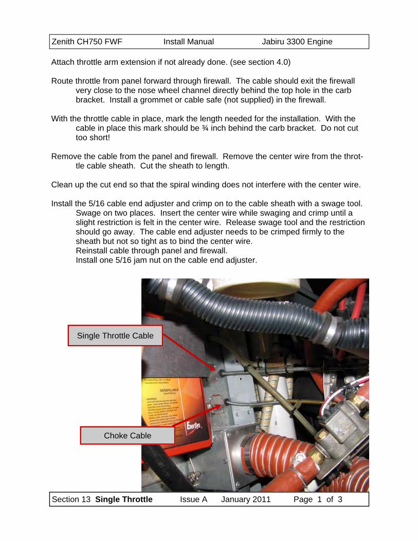
Attach throttle arm extension if not already done. (see section 4.0) Route throttle from panel forward through firewall. The cable should exit the firewall
very close to the nose wheel channel directly behind the top hole in the carb bracket. Install a grommet or cable safe (not supplied) in the firewall.
With the throttle cable in place, mark the length needed for the installation. With the
cable in place this mark should be ¾ inch behind the carb bracket. Do not cut too short!
Remove the cable from the panel and firewall. Remove the center wire from the throt-
tle cable sheath. Cut the sheath to length. Clean up the cut end so that the spiral winding does not interfere with the center wire. Install the 5/16 cable end adjuster and crimp on to the cable sheath with a swage tool.
Swage on two places. Insert the center wire while swaging and crimp until a slight restriction is felt in the center wire. Release swage tool and the restriction should go away. The cable end adjuster needs to be crimped firmly to the sheath but not so tight as to bind the center wire. Reinstall cable through panel and firewall. Install one 5/16 jam nut on the cable end adjuster.
Choke Cable
Single Throttle Cable
Zenith CH750 FWF Install Manual Jabiru 3300 Engine
Section 13 Single Throttle Issue A January 2011 Page 2 of 3
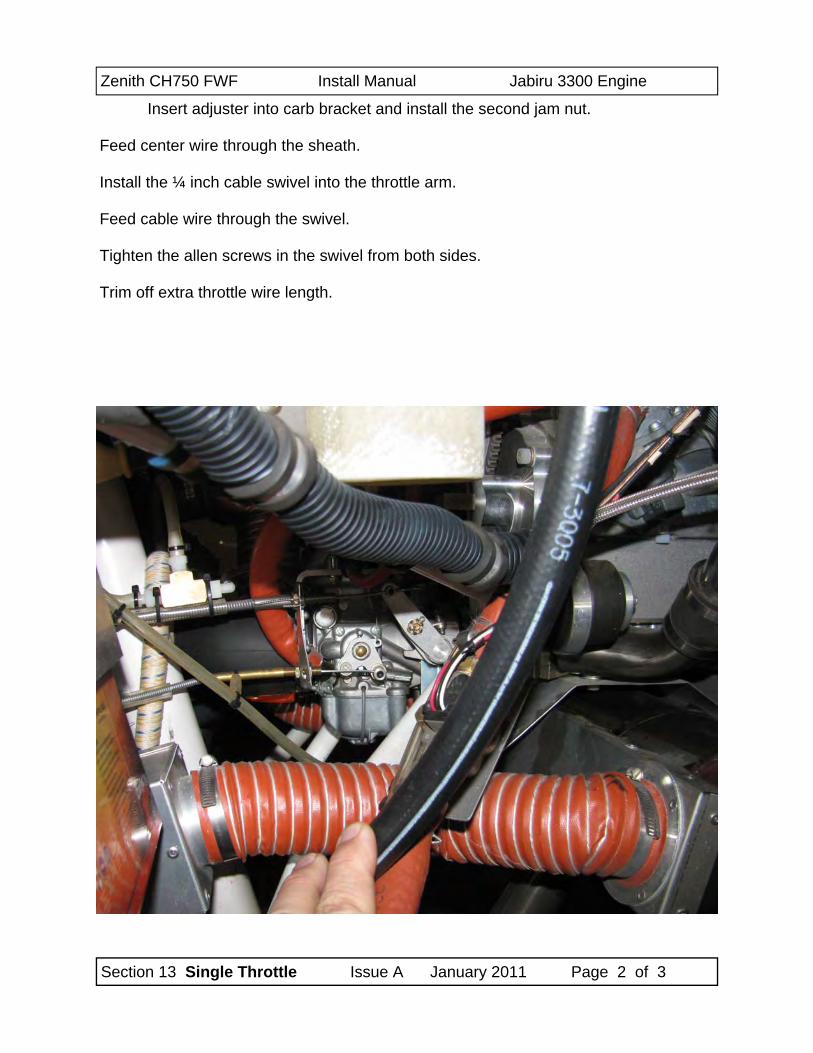
Insert adjuster into carb bracket and install the second jam nut.
Feed center wire through the sheath. Install the ¼ inch cable swivel into the throttle arm. Feed cable wire through the swivel. Tighten the allen screws in the swivel from both sides.
Trim off extra throttle wire length.
Zenith CH750 FWF Install Manual Jabiru 3300 Engine
Section 13 Single Throttle Issue A January 2011 Page 3 of 3
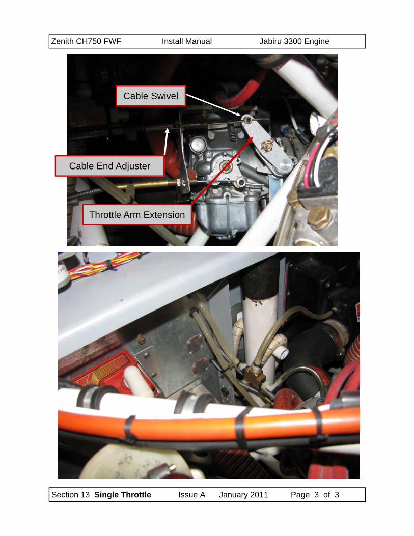
Cable Swivel
Throttle Arm Extension
Cable End Adjuster
Zenith CH750 FWF Install Manual Jabiru 3300 Engine
Section 14 Throttle Assembly Issue A January 2011 Page 1 of 5
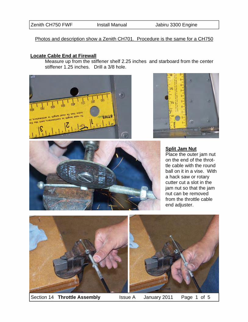
Photos and description show a Zenith CH701. Procedure is the same for a CH750
Locate Cable End at Firewall
Measure up from the stiffener shelf 2.25 inches and starboard from the center stiffener 1.25 inches. Drill a 3/8 hole.
Split Jam Nut Place the outer jam nut on the end of the throt-tle cable with the round ball on it in a vise. With a hack saw or rotary cutter cut a slot in the jam nut so that the jam nut can be removed from the throttle cable end adjuster.
Zenith CH750 FWF Install Manual Jabiru 3300 Engine
Section 14 Throttle Assembly Issue A January 2011 Page 2 of 5
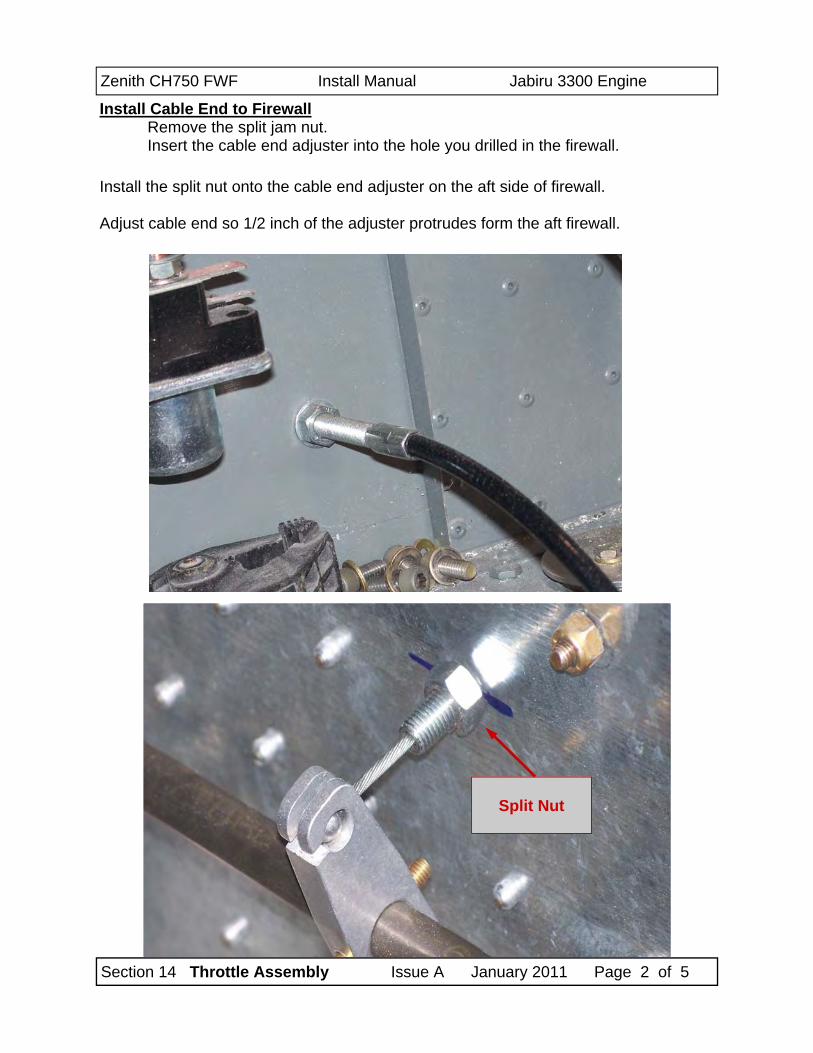
Install Cable End to Firewall Remove the split jam nut. Insert the cable end adjuster into the hole you drilled in the firewall.
Install the split nut onto the cable end adjuster on the aft side of firewall. Adjust cable end so 1/2 inch of the adjuster protrudes form the aft firewall.
Split Nut
Zenith CH750 FWF Install Manual Jabiru 3300 Engine
Section 14 Throttle Assembly Issue A January 2011 Page 3 of 5
Assemble Throttle Cross Rod Install the throttle output lever (the short lever) onto the cross rod. The slot will be facing to the rear. Install the two throttle input levers about 1.5 inches in from each end. Do not drill at this time. Install the two support blocks on the ends of the cross rod.
Attach Cross Rod Assembly to Throttle System Attach the output lever to the throttle cable by inserting the swaged ball into the receiver. Adjust the position of the output lever on the shaft so that the cross rod is cen-
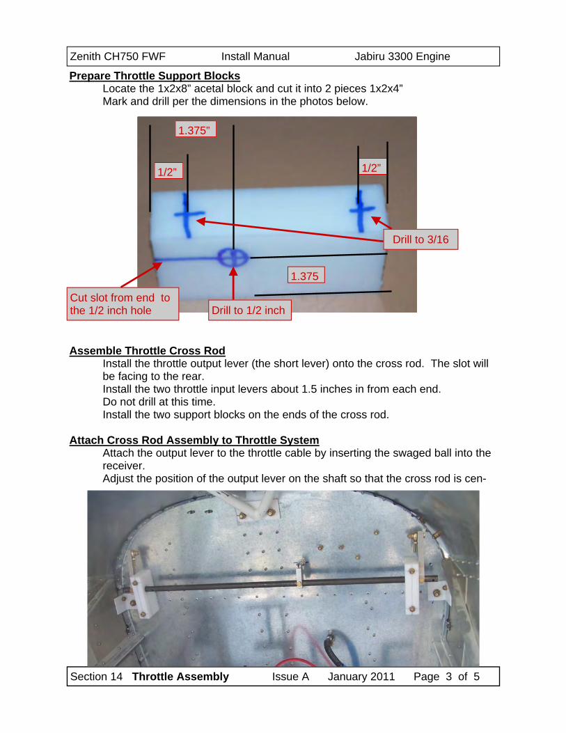
Prepare Throttle Support Blocks Locate the 1x2x8” acetal block and cut it into 2 pieces 1x2x4” Mark and drill per the dimensions in the photos below.
Cut slot from end to the 1/2 inch hole
1.375”
1/2” 1/2”
1.375
Drill to 1/2 inch
Drill to 3/16
Zenith CH750 FWF Install Manual Jabiru 3300 Engine
Section 14 Throttle Assembly Issue A January 2011 Page 4 of 5
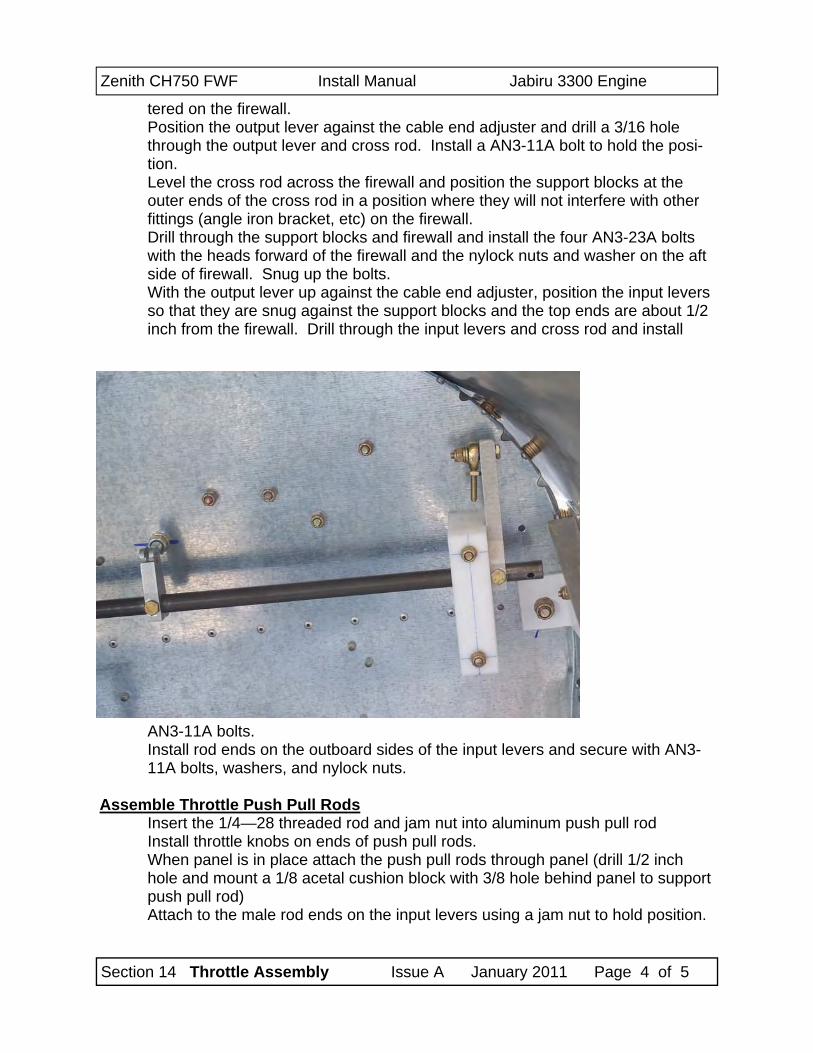
tered on the firewall. Position the output lever against the cable end adjuster and drill a 3/16 hole through the output lever and cross rod. Install a AN3-11A bolt to hold the posi-tion. Level the cross rod across the firewall and position the support blocks at the outer ends of the cross rod in a position where they will not interfere with other fittings (angle iron bracket, etc) on the firewall. Drill through the support blocks and firewall and install the four AN3-23A bolts with the heads forward of the firewall and the nylock nuts and washer on the aft side of firewall. Snug up the bolts. With the output lever up against the cable end adjuster, position the input levers so that they are snug against the support blocks and the top ends are about 1/2 inch from the firewall. Drill through the input levers and cross rod and install
AN3-11A bolts. Install rod ends on the outboard sides of the input levers and secure with AN3-11A bolts, washers, and nylock nuts.
Assemble Throttle Push Pull Rods
Insert the 1/4—28 threaded rod and jam nut into aluminum push pull rod Install throttle knobs on ends of push pull rods. When panel is in place attach the push pull rods through panel (drill 1/2 inch hole and mount a 1/8 acetal cushion block with 3/8 hole behind panel to support push pull rod) Attach to the male rod ends on the input levers using a jam nut to hold position.
Zenith CH750 FWF Install Manual Jabiru 3300 Engine
Section 14 Throttle Assembly Issue A January 2011 Page 5 of 5
Attach Cable to Carb
Turn one jam nut off the end of the carb end cable adjuster. Insert the cable through the slot on the upper hole in the carb bracket Insert the drive pin from the throttle cable into the throttle arm on the carb. You may have to sand away any excess solder that is on the cable drive arm to get it into the carb throttle arm. Place a 5/8 washer over the cable drive arm behind the carb throttle arm and secure with a cotter pin. Reinstall the jam nut and adjust cable length so that when throttles are pushed all the way in that the throttle arm on the carb reached the stop on the carb.
Section 15 Oil Cooler Issue A January 2011 Page 1 of 16
Zenith CH750 FWF Install Manual Jabiru 3300 Engine
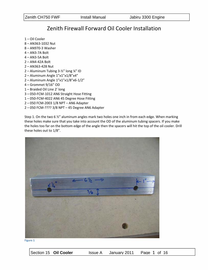
Zenith Firewall Forward Oil Cooler Installation 1 – Oil Cooler 8 – AN363‐1032 Nut 8 – AN970‐3 Washer 4 – AN3‐7A Bolt 4 – AN3‐5A Bolt 2 – AN4‐42A Bolt 2 – AN363‐428 Nut 2 – Aluminum Tubing 3‐½” long ¼” ID 2 – Aluminum Angle 1”x1”x1/8”x4” 2 – Aluminum Angle 1”x1”x1/8”x6‐1/2” 4 – Grommet 9/16” OD 1 – Braided Oil Line 2’ long 3 – 050‐FCM‐1012 AN6 Straight Hose Fitting 1 – 050‐FCM‐4022 AN6 45 Degree Hose Fitting 2 – 050 FCM‐2003 1/8 NPT – AN6 Adapter 2 – 050 FCM‐???? 3/8 NPT – 45 Degree AN6 Adapter Step 1. On the two 6 ½” aluminum angles mark two holes one inch in from each edge. When marking these holes make sure that you take into account the OD of the aluminum tubing spacers. If you make the holes too far on the bottom edge of the angle then the spacers will hit the top of the oil cooler. Drill these holes out to 1/8”.
Figure 1
Section 15 Oil Cooler Issue A January 2011 Page 2 of 16
Zenith CH750 FWF Install Manual Jabiru 3300 Engine
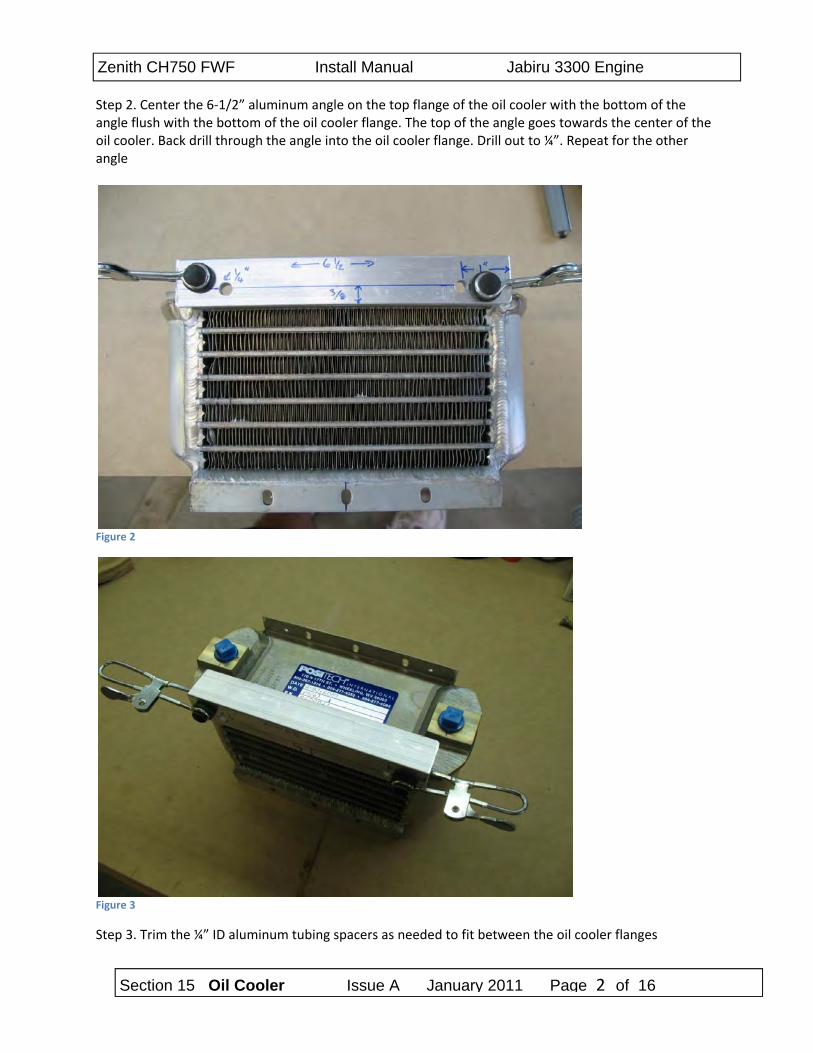
Step 2. Center the 6‐1/2” aluminum angle on the top flange of the oil cooler with the bottom of the angle flush with the bottom of the oil cooler flange. The top of the angle goes towards the center of the oil cooler. Back drill through the angle into the oil cooler flange. Drill out to ¼”. Repeat for the other angle
Figure 2
Figure 3
Step 3. Trim the ¼” ID aluminum tubing spacers as needed to fit between the oil cooler flanges
Section 15 Oil Cooler Issue A January 2011 Page 3 of 16
Zenith CH750 FWF Install Manual Jabiru 3300 Engine
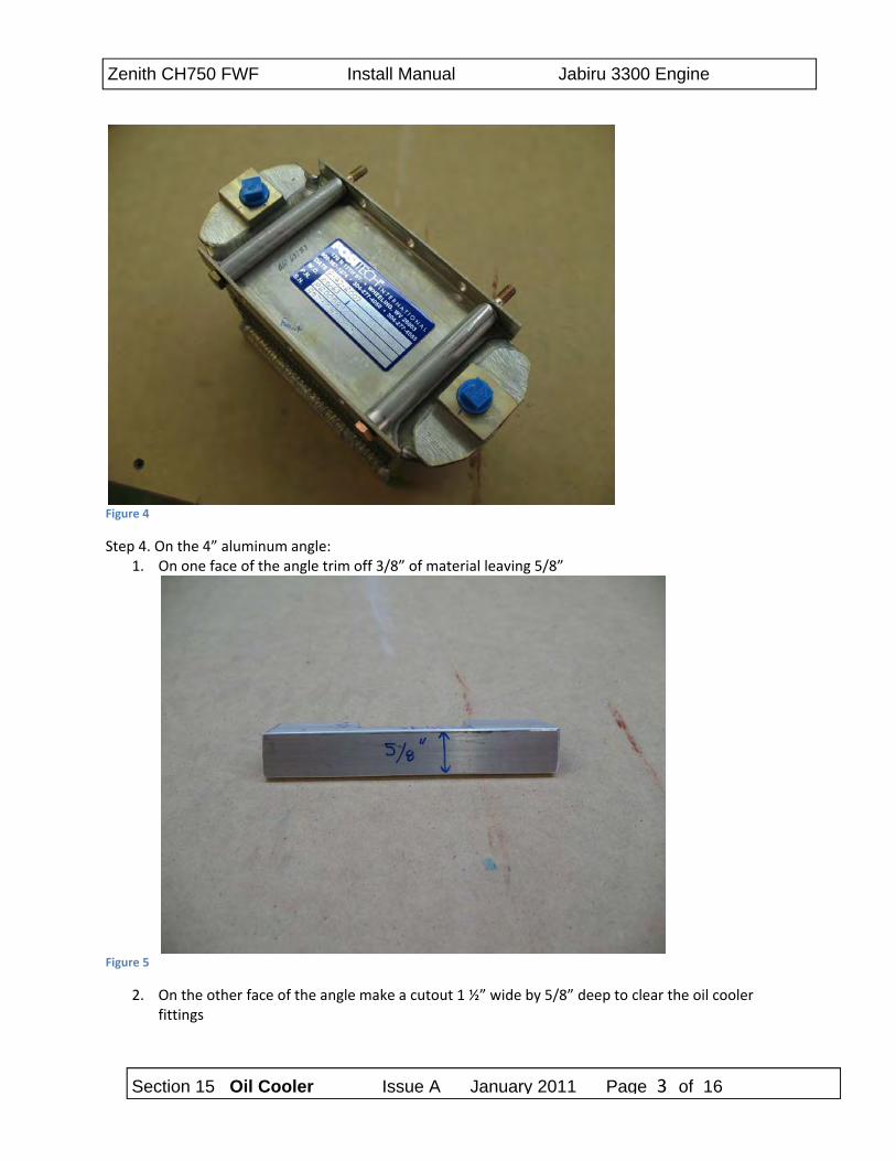
Figure 4
Step 4. On the 4” aluminum angle: 1. On one face of the angle trim off 3/8” of material leaving 5/8”
Figure 5
2. On the other face of the angle make a cutout 1 ½” wide by 5/8” deep to clear the oil cooler fittings
Section 15 Oil Cooler Issue A January 2011 Page 4 of 16
Zenith CH750 FWF Install Manual Jabiru 3300 Engine
Figure 6
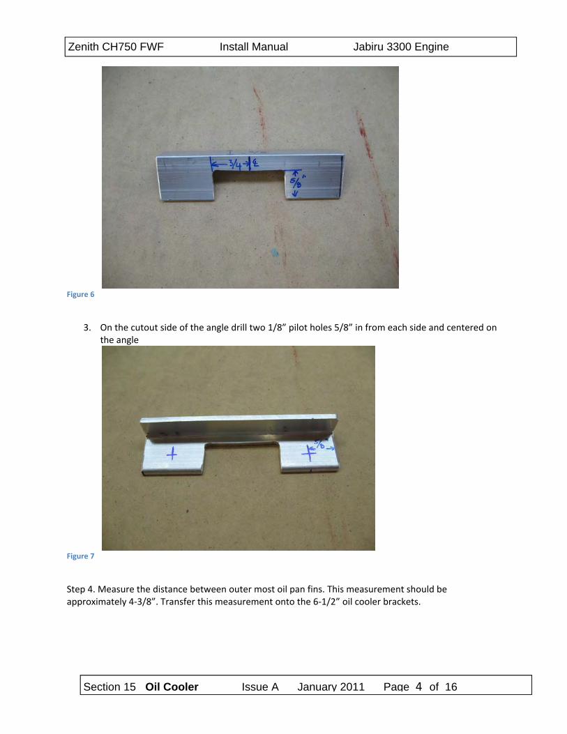
3. On the cutout side of the angle drill two 1/8” pilot holes 5/8” in from each side and centered on
the angle
Figure 7
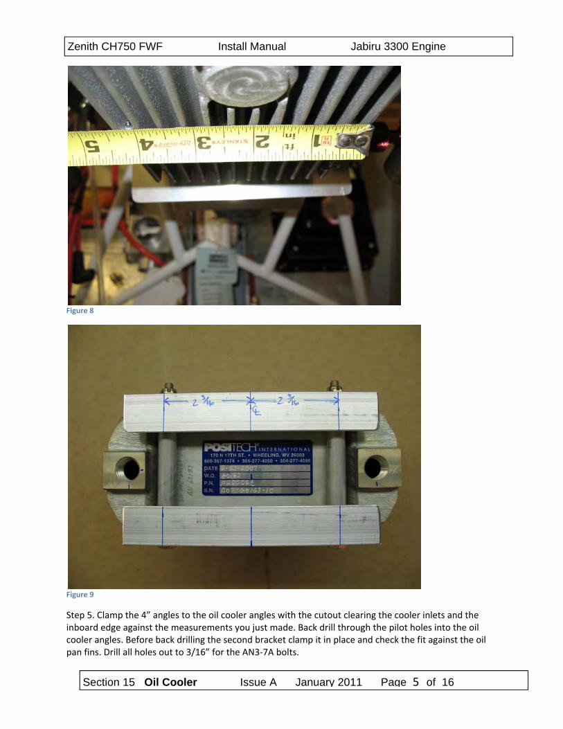
Step 4. Measure the distance between outer most oil pan fins. This measurement should be approximately 4‐3/8”. Transfer this measurement onto the 6‐1/2” oil cooler brackets.
Section 15 Oil Cooler Issue A January 2011 Page 5 of 16
Zenith CH750 FWF Install Manual Jabiru 3300 Engine
Figure 8
Figure 9
Step 5. Clamp the 4” angles to the oil cooler angles with the cutout clearing the cooler inlets and the inboard edge against the measurements you just made. Back drill through the pilot holes into the oil cooler angles. Before back drilling the second bracket clamp it in place and check the fit against the oil pan fins. Drill all holes out to 3/16” for the AN3‐7A bolts.
Section 15 Oil Cooler Issue A January 2011 Page 6 of 16
Zenith CH750 FWF Install Manual Jabiru 3300 Engine
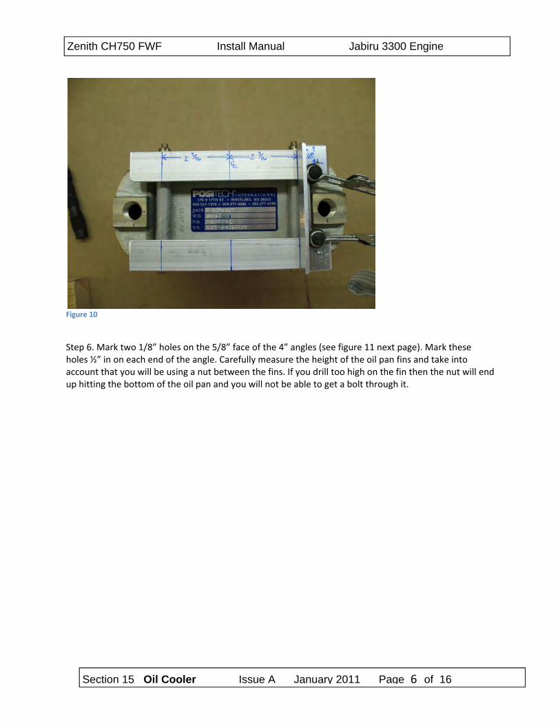
Figure 10
Step 6. Mark two 1/8” holes on the 5/8” face of the 4” angles (see figure 11 next page). Mark these holes ½” in on each end of the angle. Carefully measure the height of the oil pan fins and take into account that you will be using a nut between the fins. If you drill too high on the fin then the nut will end up hitting the bottom of the oil pan and you will not be able to get a bolt through it.
Section 15 Oil Cooler Issue A January 2011 Page 7 of 16
Zenith CH750 FWF Install Manual Jabiru 3300 Engine
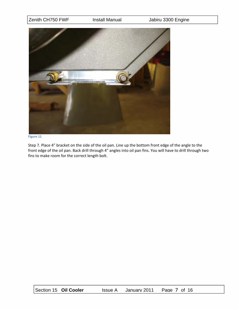
Figure 11
Step 7. Place 4” bracket on the side of the oil pan. Line up the bottom front edge of the angle to the front edge of the oil pan. Back drill through 4” angles into oil pan fins. You will have to drill through two fins to make room for the correct length bolt.
Section 15 Oil Cooler Issue A January 2011 Page 8 of 16
Zenith CH750 FWF Install Manual Jabiru 3300 Engine
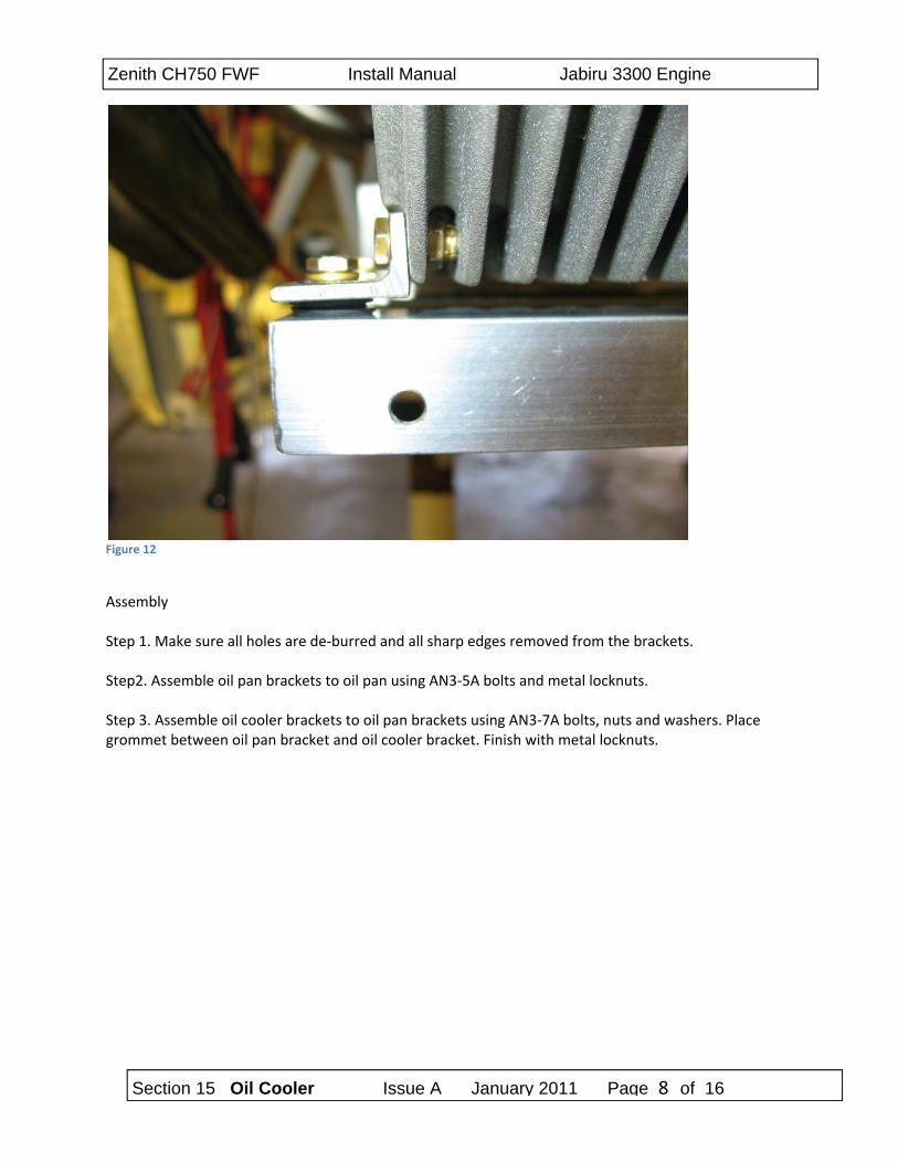
Figure 12
Assembly Step 1. Make sure all holes are de‐burred and all sharp edges removed from the brackets. Step2. Assemble oil pan brackets to oil pan using AN3‐5A bolts and metal locknuts. Step 3. Assemble oil cooler brackets to oil pan brackets using AN3‐7A bolts, nuts and washers. Place grommet between oil pan bracket and oil cooler bracket. Finish with metal locknuts.
Section 15 Oil Cooler Issue A January 2011 Page 9 of 16
Zenith CH750 FWF Install Manual Jabiru 3300 Engine
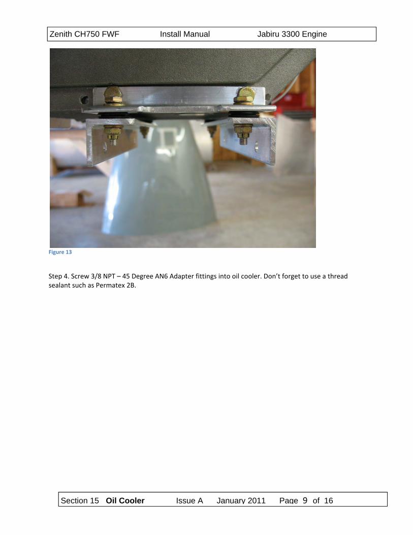
Figure 13
Step 4. Screw 3/8 NPT – 45 Degree AN6 Adapter fittings into oil cooler. Don’t forget to use a thread sealant such as Permatex 2B.
Section 15 Oil Cooler Issue A January 2011 Page 10 of 16
Zenith CH750 FWF Install Manual Jabiru 3300 Engine
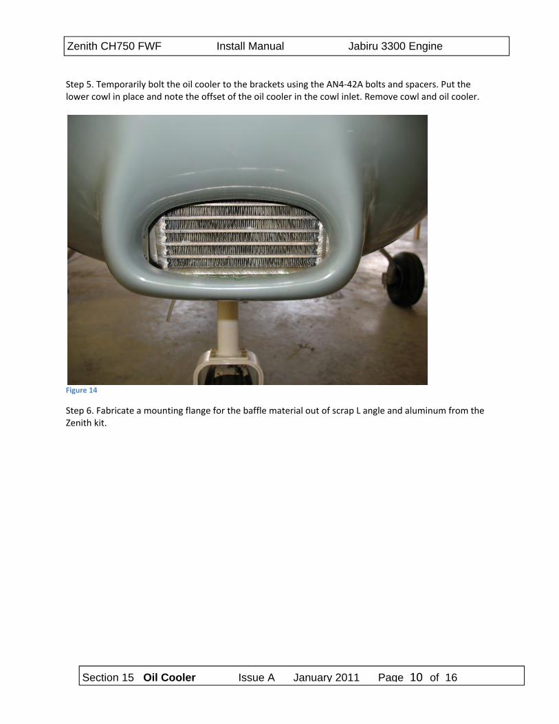
Step 5. Temporarily bolt the oil cooler to the brackets using the AN4‐42A bolts and spacers. Put the lower cowl in place and note the offset of the oil cooler in the cowl inlet. Remove cowl and oil cooler.
Figure 14
Step 6. Fabricate a mounting flange for the baffle material out of scrap L angle and aluminum from the Zenith kit.
Section 15 Oil Cooler Issue A January 2011 Page 11 of 16
Zenith CH750 FWF Install Manual Jabiru 3300 Engine
Figure 15
Figure 16
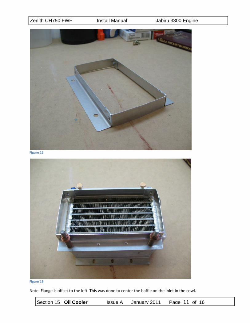
Note: Flange is offset to the left. This was done to center the baffle on the inlet in the cowl.
Section 15 Oil Cooler Issue A January 2011 Page 12 of 16
Zenith CH750 FWF Install Manual Jabiru 3300 Engine
Figure 17
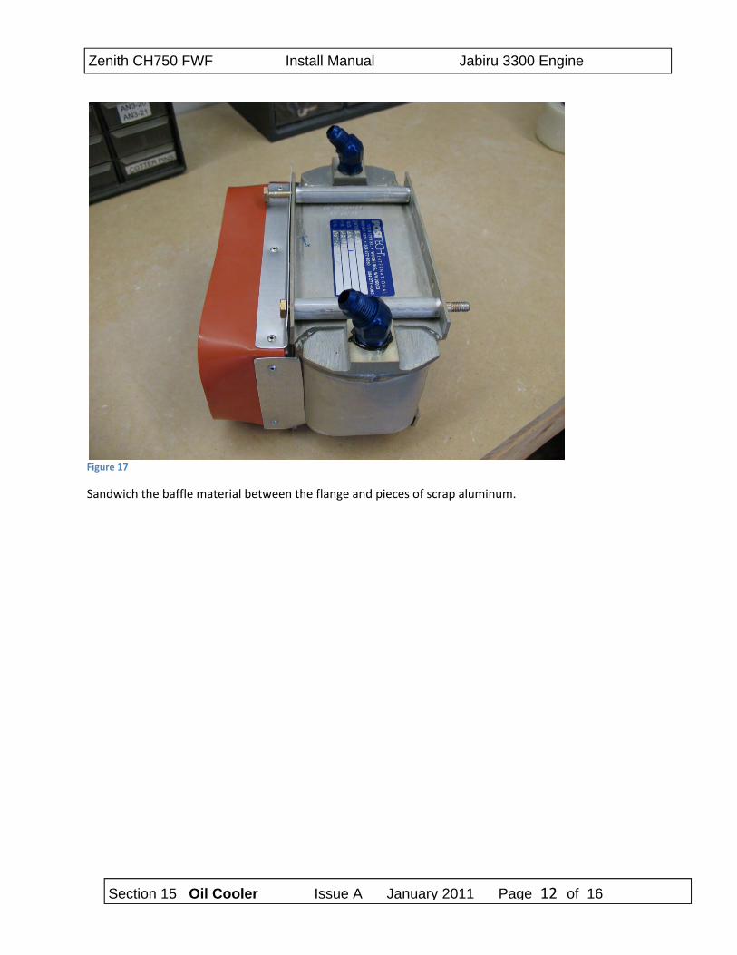
Sandwich the baffle material between the flange and pieces of scrap aluminum.
Section 15 Oil Cooler Issue A January 2011 Page 13 of 16
Zenith CH750 FWF Install Manual Jabiru 3300 Engine
Figure 18
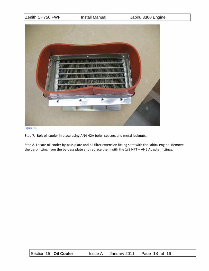
Step 7. Bolt oil cooler in place using AN4‐42A bolts, spacers and metal locknuts. Step 8. Locate oil cooler by‐pass plate and oil filter extension fitting sent with the Jabiru engine. Remove the barb fitting from the by‐pass plate and replace them with the 1/8 NPT – AN6 Adapter fittings.
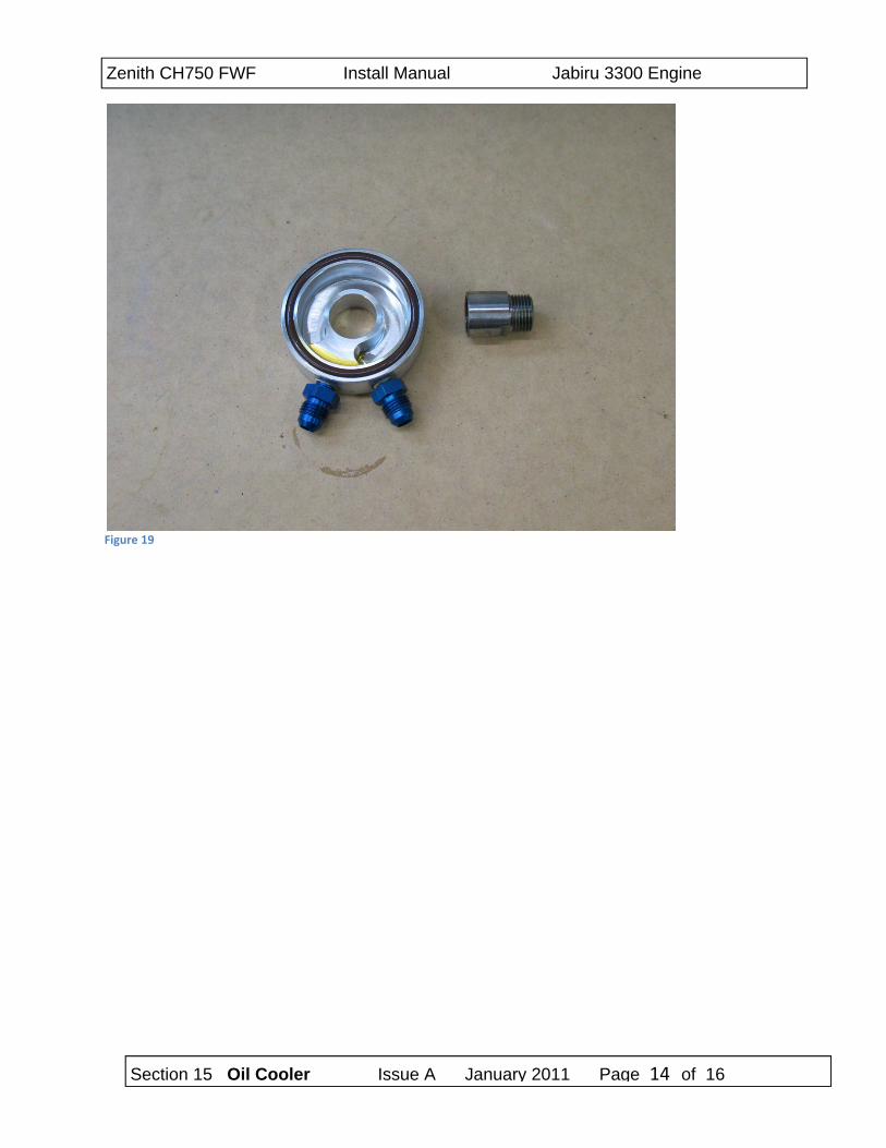
Section 15 Oil Cooler Issue A January 2011 Page 14 of 16
Zenith CH750 FWF Install Manual Jabiru 3300 Engine
Figure 19
Section 15 Oil Cooler Issue A January 2011 Page 15 of 16
Zenith CH750 FWF Install Manual Jabiru 3300 Engine
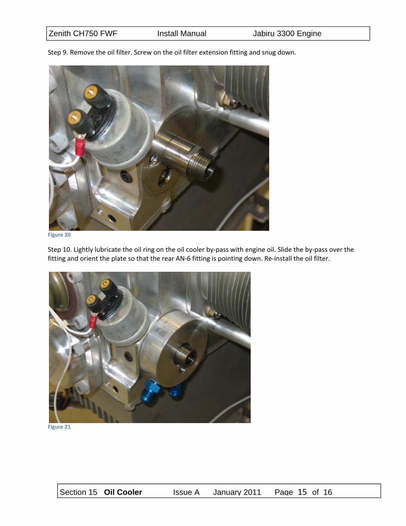
Step 9. Remove the oil filter. Screw on the oil filter extension fitting and snug down.
Figure 20
Step 10. Lightly lubricate the oil ring on the oil cooler by‐pass with engine oil. Slide the by‐pass over the fitting and orient the plate so that the rear AN‐6 fitting is pointing down. Re‐install the oil filter.
Figure 21
Section 15 Oil Cooler Issue A January 2011 Page 16 of 16
Zenith CH750 FWF Install Manual Jabiru 3300 Engine
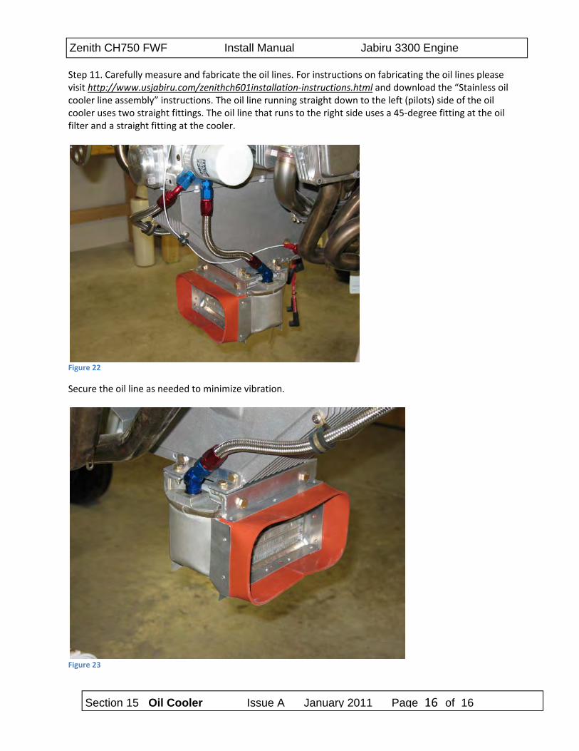
Step 11. Carefully measure and fabricate the oil lines. For instructions on fabricating the oil lines please visit http://www.usjabiru.com/zenithch601installation‐instructions.html and download the “Stainless oil cooler line assembly” instructions. The oil line running straight down to the left (pilots) side of the oil cooler uses two straight fittings. The oil line that runs to the right side uses a 45‐degree fitting at the oil filter and a straight fitting at the cooler.
Figure 22
Secure the oil line as needed to minimize vibration.
Figure 23
Jabiru J ALL Constructors Manual
Pre-Paint>Fuselage>Firewall forward>Fit propeller flange extension
1 of 2 Thursday, April 8, 2010
Pre-Paint>Fuselage>Firewall forward>Fit propeller flange extension
Objectives of this task:
To remove the universal propeller flange that is shipped with the engine and fit the model-
specific propeller flange extension to the crankshaft. While this is a straightforward
mechanical task it is most definitely a critical task and care must be taken.
The universal propeller flange is lock wired in place, however the depth of the propeller
flange extension makes the use of lock wire almost impossible and so we use a strong Loctite
to keep the flange securely fitted. This means that the cleanliness of all threads is critical.
This task will require 2 people: 1 to stop the crankshaft from moving and 1 to loosen and later
tighten the cap screws. This task is intended to be performed by the kit builder with the engine
mounted to the aircraft. In the factory we do this task while the engine is fitted to a mobile
engine stand so some of the photos will be slightly different to what the kit builder could
expect to see.
Materials and equipment required:
Loctite 620 and lockwire
Thread cleaner – Loctite 7471 or Acetone
5/16” Hex drive socket, or alternately a 5/16” Allen key cut straight and fitted to a 5/16”
socket
Torque wrench, set to 30 ft/lbs or 40 Nm
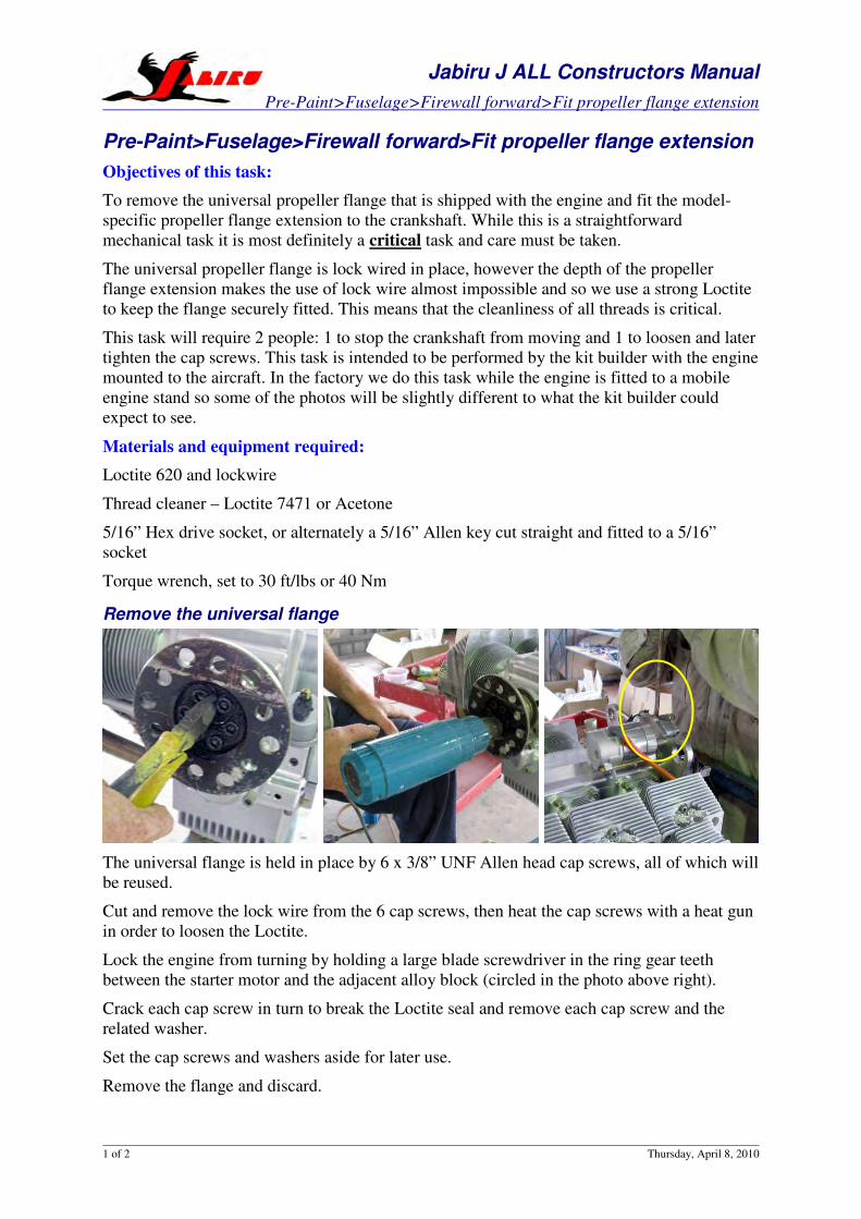
Remove the universal flange
The universal flange is held in place by 6 x 3/8” UNF Allen head cap screws, all of which will
be reused.
Cut and remove the lock wire from the 6 cap screws, then heat the cap screws with a heat gun
in order to loosen the Loctite.
Lock the engine from turning by holding a large blade screwdriver in the ring gear teeth
between the starter motor and the adjacent alloy block (circled in the photo above right).
Crack each cap screw in turn to break the Loctite seal and remove each cap screw and the
related washer.
Set the cap screws and washers aside for later use.
Remove the flange and discard.
Jabiru J ALL Constructors Manual
Pre-Paint>Fuselage>Firewall forward>Fit propeller flange extension
2 of 2 Thursday, April 8, 2010
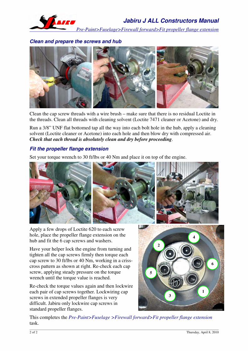
Clean and prepare the screws and hub
Clean the cap screw threads with a wire brush – make sure that there is no residual Loctite in
the threads. Clean all threads with cleaning solvent (Loctite 7471 cleaner or Acetone) and dry.
Run a 3/8” UNF flat bottomed tap all the way into each bolt hole in the hub, apply a cleaning
solvent (Loctite cleaner or Acetone) into each hole and then blow dry with compressed air.
Check that each thread is absolutely clean and dry before proceeding.
Fit the propeller flange extension
Set your torque wrench to 30 ft/lbs or 40 Nm and place it on top of the engine.
Apply a few drops of Loctite 620 to each screw
hole, place the propeller flange extension on the
hub and fit the 6 cap screws and washers.
Have your helper lock the engine from turning and
tighten all the cap screws firmly then torque each
cap screw to 30 ft/lbs or 40 Nm, working in a criss-
cross pattern as shown at right. Re-check each cap
screw, applying steady pressure on the torque
wrench until the torque value is reached.
Re-check the torque values again and then lockwire
each pair of cap screws together. Lockwiring cap
screws in extended propeller flanges is very
difficult. Jabiru only lockwire cap screws in
standard propeller flanges.
This completes the Pre-Paint>Fuselage >Firewall forward>Fit propeller flange extension
task.
4
6
2
5
3
1
Zenith CH750 FWF Install Manual Jabiru 3300 Engine
Section 17 Cowl Installation Issue A January 2011 Page 1 of 7
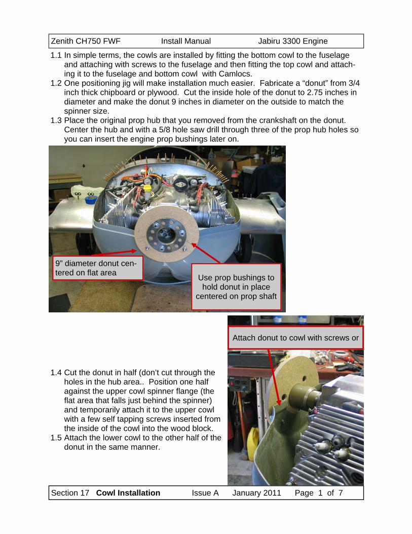
1.1 In simple terms, the cowls are installed by fitting the bottom cowl to the fuselage and attaching with screws to the fuselage and then fitting the top cowl and attach-ing it to the fuselage and bottom cowl with Camlocs.
1.2 One positioning jig will make installation much easier. Fabricate a “donut” from 3/4 inch thick chipboard or plywood. Cut the inside hole of the donut to 2.75 inches in diameter and make the donut 9 inches in diameter on the outside to match the spinner size.
1.3 Place the original prop hub that you removed from the crankshaft on the donut. Center the hub and with a 5/8 hole saw drill through three of the prop hub holes so you can insert the engine prop bushings later on.
9” diameter donut cen-tered on flat area Use prop bushings to
hold donut in place centered on prop shaft
Attach donut to cowl with screws or
1.4 Cut the donut in half (don’t cut through the holes in the hub area.. Position one half against the upper cowl spinner flange (the flat area that falls just behind the spinner) and temporarily attach it to the upper cowl with a few self tapping screws inserted from the inside of the cowl into the wood block.
1.5 Attach the lower cowl to the other half of the donut in the same manner.
Zenith CH750 FWF Install Manual Jabiru 3300 Engine
Section 17 Cowl Installation Issue A January 2011 Page 2 of 7
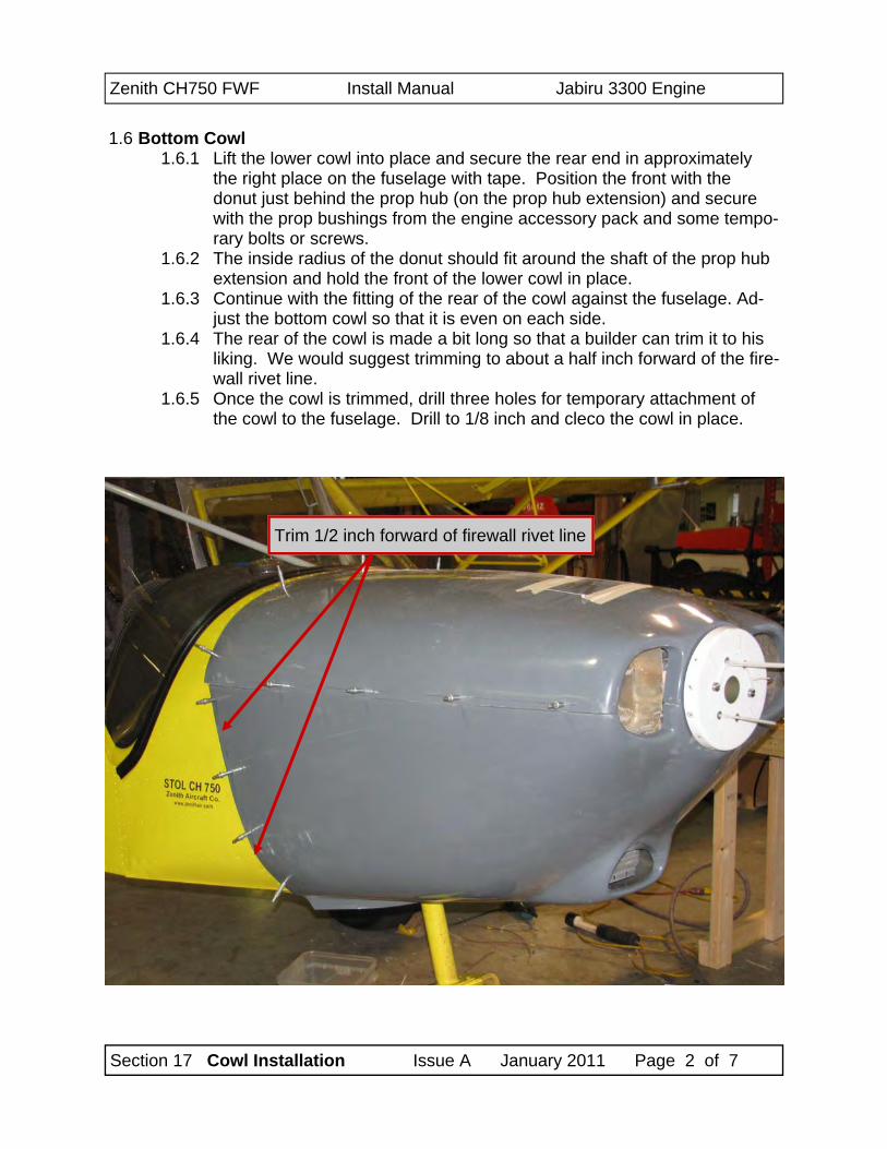
1.6 Bottom Cowl 1.6.1 Lift the lower cowl into place and secure the rear end in approximately
the right place on the fuselage with tape. Position the front with the donut just behind the prop hub (on the prop hub extension) and secure with the prop bushings from the engine accessory pack and some tempo-rary bolts or screws.
1.6.2 The inside radius of the donut should fit around the shaft of the prop hub extension and hold the front of the lower cowl in place.
1.6.3 Continue with the fitting of the rear of the cowl against the fuselage. Ad-just the bottom cowl so that it is even on each side.
1.6.4 The rear of the cowl is made a bit long so that a builder can trim it to his liking. We would suggest trimming to about a half inch forward of the fire-wall rivet line.
1.6.5 Once the cowl is trimmed, drill three holes for temporary attachment of the cowl to the fuselage. Drill to 1/8 inch and cleco the cowl in place.
Trim 1/2 inch forward of firewall rivet line
Zenith CH750 FWF Install Manual Jabiru 3300 Engine
Section 17 Cowl Installation Issue A January 2011 Page 3 of 7
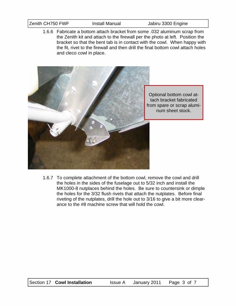
1.6.6 Fabricate a bottom attach bracket from some .032 aluminum scrap from the Zenith kit and attach to the firewall per the photo at left. Position the bracket so that the bent tab is in contact with the cowl. When happy with the fit, rivet to the firewall and then drill the final bottom cowl attach holes and cleco cowl in place.
Optional bottom cowl at-tach bracket fabricated
from spare or scrap alumi-num sheet stock.
1.6.7 To complete attachment of the bottom cowl, remove the cowl and drill the holes in the sides of the fuselage out to 5/32 inch and install the MK1000-8 nutplaces behind the holes. Be sure to countersink or dimple the holes for the 3/32 flush rivets that attach the nutplates. Before final riveting of the nutplates, drill the hole out to 3/16 to give a bit more clear-ance to the #8 machine screw that will hold the cowl.
Zenith CH750 FWF Install Manual Jabiru 3300 Engine
Section 17 Cowl Installation Issue A January 2011 Page 4 of 7
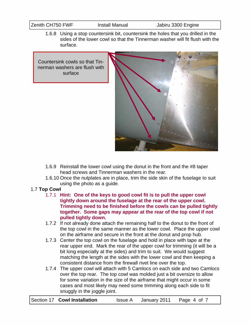
1.6.8 Using a stop countersink bit, countersink the holes that you drilled in the sides of the lower cowl so that the Tinnerman washer will fit flush with the surface.
Countersink cowls so that Tin-nerman washers are flush with
surface
1.6.9 Reinstall the lower cowl using the donut in the front and the #8 taper head screws and Tinnerman washers in the rear.
1.6.10 Once the nutplates are in place, trim the side skin of the fuselage to suit using the photo as a guide.
1.7 Top Cowl 1.7.1 Hint: One of the keys to good cowl fit is to pull the upper cowl
tightly down around the fuselage at the rear of the upper cowl. Trimming need to be finished before the cowls can be pulled tightly together. Some gaps may appear at the rear of the top cowl if not pulled tightly down.
1.7.2 If not already done attach the remaining half to the donut to the front of the top cowl in the same manner as the lower cowl. Place the upper cowl on the airframe and secure in the front at the donut and prop hub.
1.7.3 Center the top cowl on the fuselage and hold in place with tape at the rear upper end. Mark the rear of the upper cowl for trimming (it will be a bit long especially at the sides) and trim to suit. We would suggest matching the length at the sides with the lower cowl and then keeping a consistent distance from the firewall rivet line over the top.
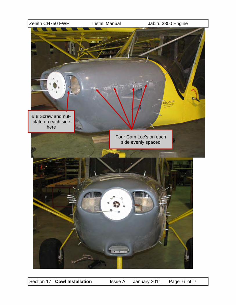
1.7.4 The upper cowl will attach with 5 Camlocs on each side and two Camlocs over the top rear. The top cowl was molded just a bit oversize to allow for some variation in the size of the airframe that might occur in some cases and most likely may need some trimming along each side to fit snuggly in the joggle joint.
Zenith CH750 FWF Install Manual Jabiru 3300 Engine
Section 17 Cowl Installation Issue A January 2011 Page 5 of 7
1.7.5 When satisfied with the rear trim, again fasten the rear in place with tape. Try to center the upper cowl on the fuselage before taping. Using some more tape, pull the sides of the top cowl down over the lower cowl and mark for trimming for a good fit in the joggle joint. Trim with a long sand-ing block with 80 grit paper or a Permagrit abrasive block.
1.7.6 When cowl is trimmed to fit, installation of the Camlocs can begin. Use a 1/8 drill to initially drill the Camloc locations and clecos to fasten the top and bottom together. Start at the front and locate a Camloc about mid-way in the front flange. For the sake of symmetry, drill each side in the same location. Insert clecos to hold the cowls together.
1.7.7 Mark the sides of the cowl to evenly space 4 Camlocs on each side. Plan on locating the most forward Camlocc about six to eight inches be-hind the bend at the front and the rear Camlocs about 5/8 inch forward of the trailing edge of the upper cowl. Locate the holes so that they are slightly below the center line of the joggle joint. Again, make each side the same. Drill to 1/8 inch and install clecos to hold the cowls together.
1.7.8 Finally , evenly space the two Camlocs on the top rear of the upper cowl. Drill to 1/8 and install clecos to hold the cowls in place.
1.7.9 Installation of the Camloc receptacles is next. Camloc receptacles are installed similar to nutplates. Drill the 1/8 holes in the loawe cowl hole out to 5/16. Insert a 5/16 bolt into the hole and into a Camloc receptacle (the bolt keeps the Camloc centered in the hole) and use a 3/32 drill to backdrill the Camloc attach holes. Counter sink the Camloc attach holes so the 3/32 rivets will be flush and rivet the camloc body in place.
1.7.10 Drill a 1/4 inch hole in the upper cowl for the Camloc insert. Make a small notch in one side of the hole to allow the pin to fit through. On the sides of the cowl the Camloc receptacles are installed on the back side of the joggle joint and #6 Camloc inserts are used. At the top rear the bod-ies are riveted to the under side of the fuselage skin and #2 Camolc in-serts are used.
1.7.11 When all camlocs are in place, reinstall the bottom cowl without the donut. Lower the top cowl in place and secure with the Camlocs.
Zenith CH750 FWF Install Manual Jabiru 3300 Engine
Section 17 Cowl Installation Issue A January 2011 Page 6 of 7
# 8 Screw and nut-plate on each side
here
Four Cam Loc’s on each side evenly spaced
Zenith CH750 FWF Install Manual Jabiru 3300 Engine
Section 17 Cowl Installation Issue A January 2011 Page 7 of 7
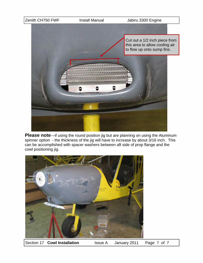
Cut out a 1/2 inch piece from this area to allow cooling air to flow up onto sump fins.
Please note—if using the round position jig but are planning on using the Aluminum spinner option - the thickness of the jig will have to increase by about 3/16 inch. This can be accomplished with spacer washers between aft side of prop flange and the cowl positioning jig.
Zenith CH750 FWF Install Manual Jabiru 3300 Engine
Section 18 Propeller Installation Issue A January 2011 Page 1 of 2
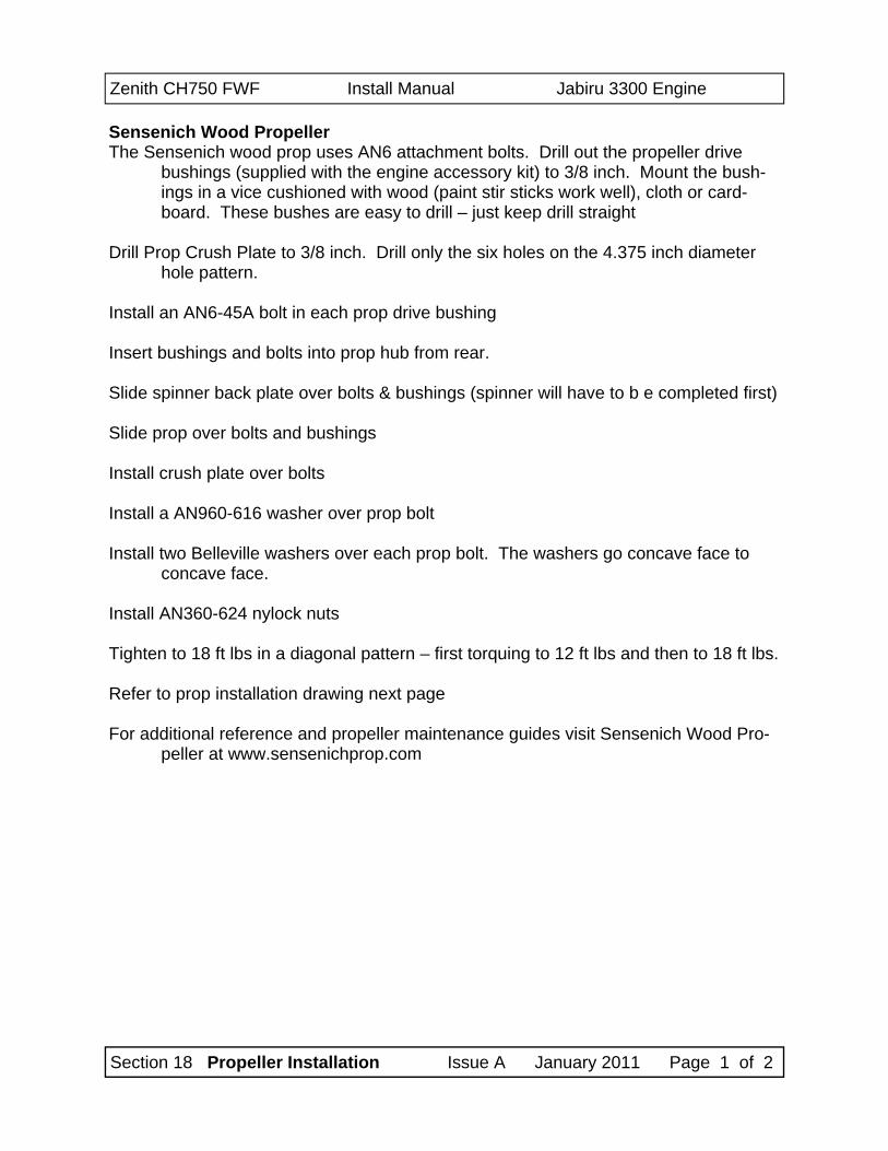
Sensenich Wood Propeller The Sensenich wood prop uses AN6 attachment bolts. Drill out the propeller drive
bushings (supplied with the engine accessory kit) to 3/8 inch. Mount the bush-ings in a vice cushioned with wood (paint stir sticks work well), cloth or card-board. These bushes are easy to drill – just keep drill straight
Drill Prop Crush Plate to 3/8 inch. Drill only the six holes on the 4.375 inch diameter
hole pattern. Install an AN6-45A bolt in each prop drive bushing Insert bushings and bolts into prop hub from rear. Slide spinner back plate over bolts & bushings (spinner will have to b e completed first) Slide prop over bolts and bushings Install crush plate over bolts Install a AN960-616 washer over prop bolt Install two Belleville washers over each prop bolt. The washers go concave face to
concave face. Install AN360-624 nylock nuts Tighten to 18 ft lbs in a diagonal pattern – first torquing to 12 ft lbs and then to 18 ft lbs. Refer to prop installation drawing next page For additional reference and propeller maintenance guides visit Sensenich Wood Pro-
peller at www.sensenichprop.com
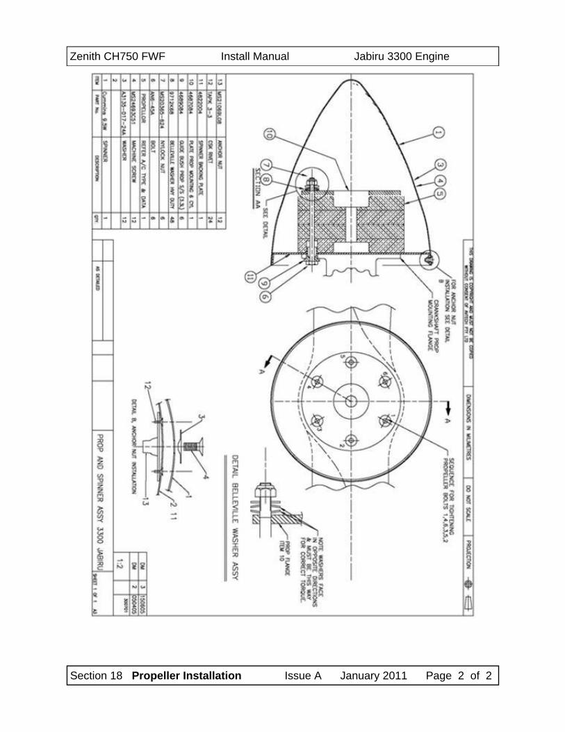
Zenith CH750 FWF Install Manual Jabiru 3300 Engine
Section 18 Propeller Installation Issue A January 2011 Page 2 of 2
Zenith CH750 FWF Install Manual Jabiru 3300 Engine
Section 19 Spinner Issue A January 2011 Page 1
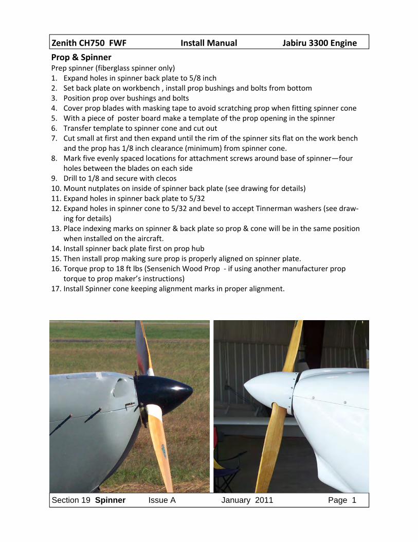
Prop & Spinner Prep spinner (fiberglass spinner only) 1. Expand holes in spinner back plate to 5/8 inch 2. Set back plate on workbench , install prop bushings and bolts from bottom 3. Position prop over bushings and bolts 4. Cover prop blades with masking tape to avoid scratching prop when fitting spinner cone 5. With a piece of poster board make a template of the prop opening in the spinner 6. Transfer template to spinner cone and cut out 7. Cut small at first and then expand until the rim of the spinner sits flat on the work bench
and the prop has 1/8 inch clearance (minimum) from spinner cone. 8. Mark five evenly spaced locations for attachment screws around base of spinner—four
holes between the blades on each side 9. Drill to 1/8 and secure with clecos 10. Mount nutplates on inside of spinner back plate (see drawing for details) 11. Expand holes in spinner back plate to 5/32 12. Expand holes in spinner cone to 5/32 and bevel to accept Tinnerman washers (see draw‐
ing for details) 13. Place indexing marks on spinner & back plate so prop & cone will be in the same position
when installed on the aircraft. 14. Install spinner back plate first on prop hub 15. Then install prop making sure prop is properly aligned on spinner plate. 16. Torque prop to 18 ft lbs (Sensenich Wood Prop ‐ if using another manufacturer prop
torque to prop maker’s instructions) 17. Install Spinner cone keeping alignment marks in proper alignment.
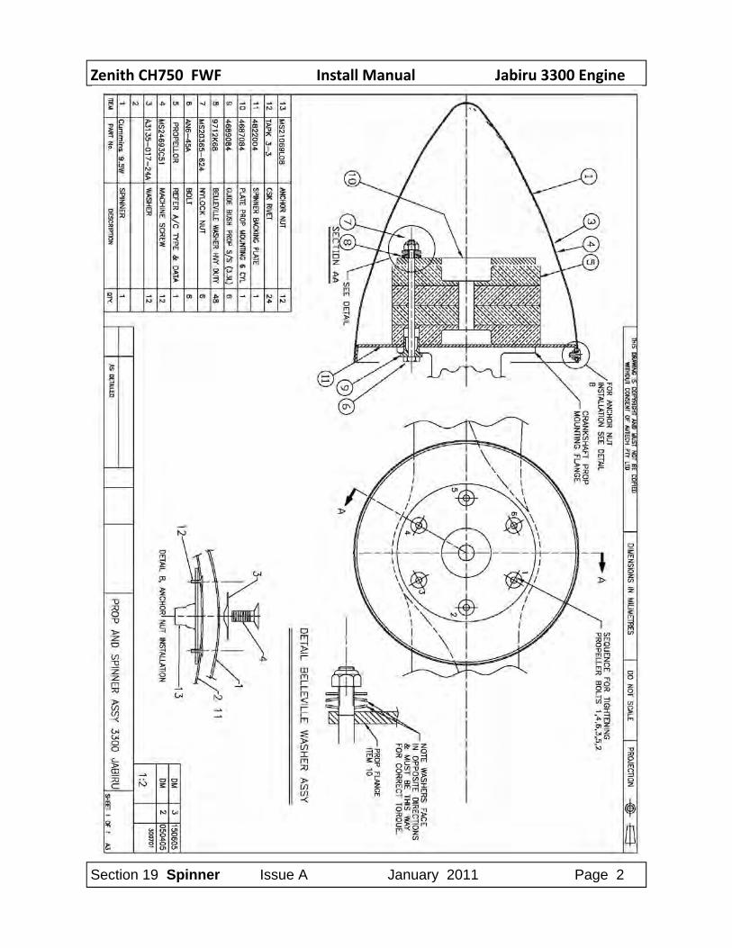
Zenith CH750 FWF Install Manual Jabiru 3300 Engine
Section 19 Spinner Issue A January 2011 Page 2
Zenith CH750 FWF Install Manual Jabiru 3300 Engine
Section 19 Spinner Issue A January 2011 Page 3
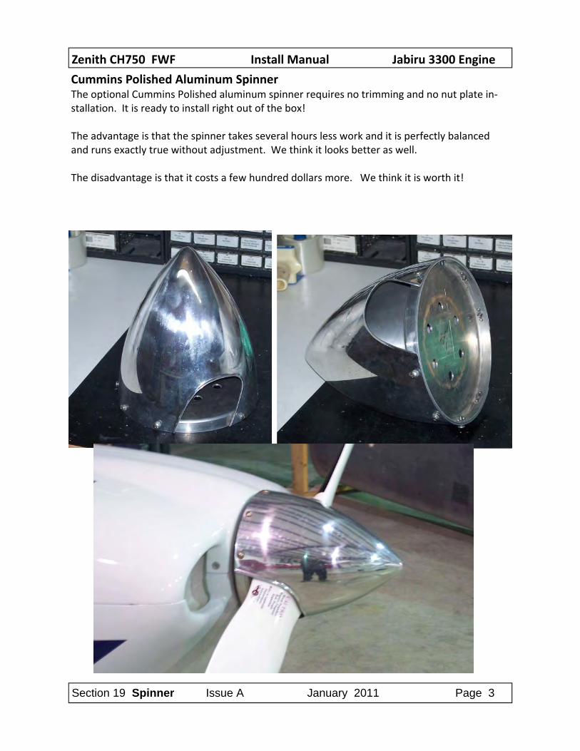
Cummins Polished Aluminum Spinner The optional Cummins Polished aluminum spinner requires no trimming and no nut plate in‐stallation. It is ready to install right out of the box! The advantage is that the spinner takes several hours less work and it is perfectly balanced and runs exactly true without adjustment. We think it looks better as well. The disadvantage is that it costs a few hundred dollars more. We think it is worth it!