Process Combustion Technology Forum · Exceeds API 537 wind and rain recommendations
29
©2016 John Zink Company, LLC 1 Pilots for Reliability Steam Traps for Proper Operation Process Combustion Technology Forum
-
Upload
vuongtuong -
Category
Documents
-
view
238 -
download
1
Transcript of Process Combustion Technology Forum · Exceeds API 537 wind and rain recommendations

©2016 John Zink Company, LLC 1
Pilots for Reliability
Steam Traps for
Proper Operation
Process Combustion Technology Forum

©2016 John Zink Company, LLC 2 This presentation is not, and should not be considered, legal advice.
Important Notice
The information contained in these materials is for informational purposes only and is provided “AS IS”, without warranties of any kind. Your use of the information contained herein is at your sole risk. We expressly disclaim any express or implied representations, warranties or guaranties, including without limitation, the implied warranties of merchantability and fitness for a particular purpose. We will have absolutely no liability (whether direct, indirect or consequential) in connection with these materials (and/or the information contained therein) including without limitation, any liability for damage to person or property. We also reserve the right to make subsequent changes to the materials without prior notice. For purposes of this notification, “We” includes John Zink Company LLC and its affiliates and their respective employees, partners, principles, agents and representatives, and any third-party providers or sources of information or data.
johnzinkhamworthy.com/trademarks
©2016 John Zink Company, LLC 3 This presentation is not, and should not be considered, legal advice.
If it doesn’t light
this time let’s try
your idea of using
the flame thrower.
How Not To Light Your Flare

©2016 John Zink Company, LLC 4 This presentation is not, and should not be considered, legal advice.
Pilot Fundamentals
The pilot is the most important piece
of equipment on the flare system.

©2016 John Zink Company, LLC 5 This presentation is not, and should not be considered, legal advice.
Pilot Fundamentals
►What are the key goals for a properly
designed pilot?
►Reliable and automatic pilot ignition for safety
and to meet local regulations
►Prevent pilot flame from being extinguished
►Provide pilot flame stability per API 537
recommendations
►Accurate and quick detection
©2016 John Zink Company, LLC 6 This presentation is not, and should not be considered, legal advice.
Pilot Detection / Ignition
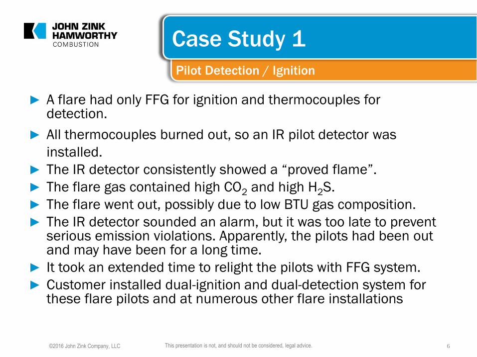
Case Study 1
► A flare had only FFG for ignition and thermocouples for detection.
► All thermocouples burned out, so an IR pilot detector was
installed.
► The IR detector consistently showed a “proved flame”.
► The flare gas contained high CO2 and high H2S.
► The flare went out, possibly due to low BTU gas composition.
► The IR detector sounded an alarm, but it was too late to prevent serious emission violations. Apparently, the pilots had been out and may have been for a long time.
► It took an extended time to relight the pilots with FFG system.
► Customer installed dual-ignition and dual-detection system for these flare pilots and at numerous other flare installations

©2016 John Zink Company, LLC 7 This presentation is not, and should not be considered, legal advice.
Dual Ignition & Detection
►Ignition
►InstaFire® Pilot
►ZEUS™ Pilot
►FFG
►Detection
►Ionization
►Thermocouple
►SoundPROOF® System

©2016 John Zink Company, LLC 8 This presentation is not, and should not be considered, legal advice.
Pilot Ignition Systems
►Flame Front Generator
►Spark Ignition

©2016 John Zink Company, LLC 9 This presentation is not, and should not be considered, legal advice.
Conventional FFG
►Flame Front Generator
►Original ignition system
►The Flame Front Generator (FFG) is the most
common method for lighting a flare pilot.

©2016 John Zink Company, LLC 10 This presentation is not, and should not be considered, legal advice.
Conventional FFG
► Method – Send a fireball through a pipe to the pilot.

©2016 John Zink Company, LLC 11 This presentation is not, and should not be considered, legal advice.
Spark electrode
Direct Spark Ignition (InstaFire pilot)
►Ignition is achieved by a heavy duty “spark
plug type” electrode mounted in the pilot
nozzle

©2016 John Zink Company, LLC 12 This presentation is not, and should not be considered, legal advice.
Comparison of Ignition Systems
CONVENTIONAL FFG 1. Compressed air required
2. 1” diameter ignition line
3. Main components at grade
4. Automatic or manual –
Operator attention may be
needed
DIRECT SPARK
1. Compressed air not req’d
2. No ignition line required
3. Not all components at grade
4. Provides Ignition & Monitoring
a. Operator attention not required
b. Relights within seconds

©2016 John Zink Company, LLC 13 This presentation is not, and should not be considered, legal advice.
Pilot Flame Detection
►Why Monitor Pilots?
►For your safety!
►Case Study 1 Example

©2016 John Zink Company, LLC 14 This presentation is not, and should not be considered, legal advice.
Pilot Flame Detection
►Pilot Flames Produce
►Heat
►Ionized Gases
►Light
►Sound
©2016 John Zink Company, LLC 15 This presentation is not, and should not be considered, legal advice.
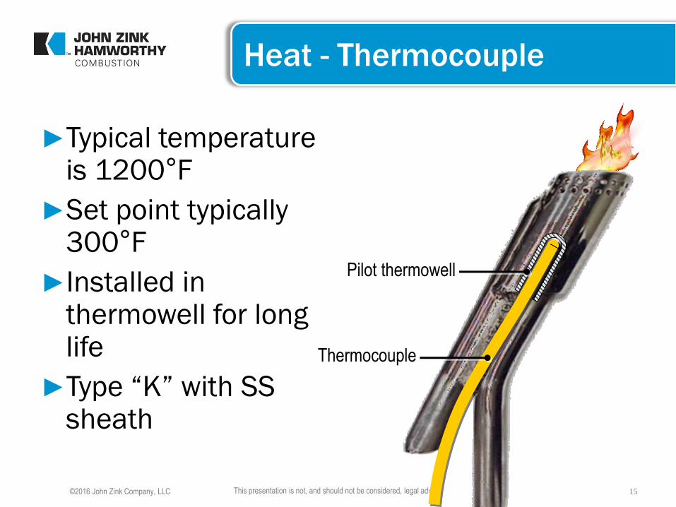
Heat - Thermocouple
►Typical temperature is 1200°F
►Set point typically 300°F
►Installed in thermowell for long life
►Type “K” with SS sheath
Pilot thermowell
Thermocouple

©2016 John Zink Company, LLC 16 This presentation is not, and should not be considered, legal advice.
Thermocouple Disadvantages
►Usually can only be replaced when flare is
down
►Long response time

©2016 John Zink Company, LLC 17 This presentation is not, and should not be considered, legal advice.
Ionized Gases - Electrode
►If a flame is present, there will be an area of ionized gases within the pilot nozzle
►Ionized gases allow current to pass from the spark rod electrode to grounded pilot
Pilot tip Ceramic insulated
spark rod/electrode

©2016 John Zink Company, LLC 18 This presentation is not, and should not be considered, legal advice.
SoundPROOF System
►Listens for the unique
sound generated by
pilot
►Uses the pilot ignition
line for sound
transmission
GAS LINE
O
N
O
FF
AIR
GAS
DRAIN
FLARE
PILOT
FLAME
MONITOR
•TM

©2016 John Zink Company, LLC 19 This presentation is not, and should not be considered, legal advice.
SoundPROOF Pilot Monitoring System
►Distinguishes individual pilots
►Quick response time
►Mounted at grade
►Maintained while flare is operating

©2016 John Zink Company, LLC 20 This presentation is not, and should not be considered, legal advice.
Pilot Monitoring Comparison
Distinguish
Individual
Pilot?
Installation/
Maintenance
Response
Weather
Problems
T/C Infra-Red SoundPROOF Ionization
5 to 10 Min. Seconds++ Seconds Seconds
At tip
during
shutdown
At grade
anytime At grade
anytime
At tip
during
shutdown
Yes No Yes Yes
Rain cools
T/C
Heavy rain,
fog, & snow None None

©2016 John Zink Company, LLC 21 This presentation is not, and should not be considered, legal advice.
WindPROOF™ Pilot
►Exceeds API 537 wind and rain
recommendations
►Options:
►FFG Ignition
►Spark Ignition
►Thermocouple Detection
►InstaFire Detection
►SoundPROOF Detection

©2016 John Zink Company, LLC 22 This presentation is not, and should not be considered, legal advice.
InstaFire Fast Response Advantage
The InstaFire system can relight a pilot within approximately 4 seconds after pilot failure, compared to
thermocouples which take much longer and waste valuable time between pilot outage and re-ignition.

©2016 John Zink Company, LLC 23 This presentation is not, and should not be considered, legal advice.
Case Study 2 Conditions
►Inlet steam pressure is 10 Bar
►Design smokeless steam rate is 40,000 kg/hr.
►Pressure downstream of steam valve is ~8 Bar
►Minimum cooling steam is ~450 kg/hr.
►What is the pressure downstream of steam valve?

©2016 John Zink Company, LLC 24 This presentation is not, and should not be considered, legal advice.
FI
RO
10 Bar STEAM
Warm up bypass
Standard Disc Trap
Standard Disc Trap
To flare tip main steam ring
Existing condensate boot
at elbow before final rise
2.7 Bar Condensate Header
Previous System Installation
Case Study 2

©2016 John Zink Company, LLC 25 This presentation is not, and should not be considered, legal advice.
Improved System Installation
Case Study 2
Trap for high pressure side of steam valve
Trap for low pressure side of steam valve
Option required for condensate return system
©2016 John Zink Company, LLC 26 This presentation is not, and should not be considered, legal advice.
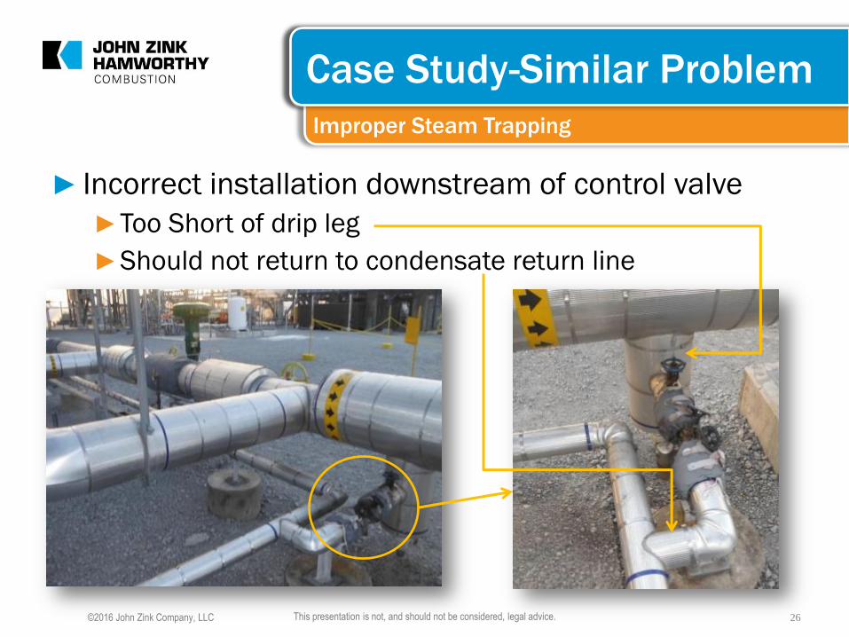
Improper Steam Trapping
Case Study-Similar Problem
► Incorrect installation downstream of control valve
►Too Short of drip leg
►Should not return to condensate return line

©2016 John Zink Company, LLC 27 This presentation is not, and should not be considered, legal advice.
Proper Steam Trapping
Case Study –Same Flare
►Correct Installation
downstream of
control valve
►Sufficiently sized
drip leg
►Open to
atmosphere

©2016 John Zink Company, LLC 28 This presentation is not, and should not be considered, legal advice.
Steam Trap Drip Leg Sizing
Steam Operation & Maintenance
Courtesy of
Armstrong
International

©2016 John Zink Company, LLC 29 This presentation is not, and should not be considered, legal advice.
Questions?


![Wi-Fi 2022 COSTA CRUISES 30 537]Wi-Fi 2022 COSTA CRUISES 30 537]](https://static.fdocuments.in/doc/165x107/61494756080bfa62601481f4/-wi-fi-2022-costa-cruises-30-537-wi-fi-2022-costa-cruises-30-537.jpg)