PROCEDURE APPROVAL COVER SHEET REMARKS: THIS PROCEDURE …
36
MAINTENANCE PROCEDURE A-11 ENCLOSURE l PROCEDURE APPROVAL COVER SHEET PROCEDURE NUMBER: M3Q-2 TITLE: REACTOR TRIP AND BYPASS ACB SEMI-ANNUAL INSPECTION AND TESTING REMARKS: THIS PROCEDURE IS SAFETY RELATED. ALL DOCUMENTATION SHALL BE MAINTAINED FOR A PERIOD OF FIVE (5) YEARS . • THIS PROCEDURE HAS BEEN REVIEWED AND DETERMINED TO BE IN COMPLIANCE WITH TECHNICAL SPECIFICATION REQUIREMENTS. REV. NO. 2 SUBMITTED DATE ECD APPROVED 95},Je; DATE MGR. QAD APPROVED N/A DATE NDE LEVEL III APPROVED DATE N/A AI REVIEWED DATE N/A • J ./ SQAE REVIEWED DATE , - 17 MAINT. MGR. APPROVED DATE ( ... :; .. \ s.o.R.c. MTG. NUMBER DATE I I GEN. MGR. - .. SALEM OPS. APPROVED DATE Enclosure 1 Page 1 of 1 PDR ADOCK 05000272 S PDR Rev. 22 I I I !
Transcript of PROCEDURE APPROVAL COVER SHEET REMARKS: THIS PROCEDURE …

MAINTENANCE PROCEDURE A-11 ENCLOSURE l
PROCEDURE APPROVAL COVER SHEET
PROCEDURE NUMBER: M3Q-2 TITLE: REACTOR TRIP AND BYPASS ACB SEMI-ANNUAL INSPECTION AND TESTING
REMARKS: THIS PROCEDURE IS SAFETY RELATED.
ALL DOCUMENTATION SHALL BE MAINTAINED FOR A PERIOD OF FIVE (5) YEARS .
• THIS PROCEDURE HAS BEEN REVIEWED AND DETERMINED TO BE IN COMPLIANCE WITH TECHNICAL SPECIFICATION REQUIREMENTS.
REV. NO. 2
SUBMITTED
~ DATE
~~ ECD APPROVED 95},Je; DATE
MGR. QAD APPROVED N/A DATE
NDE LEVEL III APPROVED DATE N/A
AI REVIEWED DATE N/A
• J
~~ ./
SQAE REVIEWED DATE
, - 17 MAINT. MGR. '~ ~~ ~ APPROVED DATE ( ~~~- q,~
~ ... :; .. \
s.o.R.c. ~.,Jl MTG. NUMBER DATE ah~~
I I
GEN. MGR. -
'~:Jr-: .. SALEM OPS. APPROVED DATE ~,,!)~
Enclosure 1 ~-e-3o-3lb-05_1_2_8_30-3fif-~-----'--ll Page 1 of 1
PDR ADOCK 05000272 S PDR
Rev. 22
I I
I !
'
MAINTENANCE PROCEDURE A-11 ENCLOSURE 1
PROCEDURE APPROVAL COVER SHEET
•
PROCEDURE NUMBER: M3Q-2 TITLE: RX TRIP AND BYPASS ACB INSPECTION AND TEST
REMARKS: This procedure is safety related. • All documentation shall be maintained for a period of five (5) years. This procedure has been reviewed and determined to be in c6mpliance
• with Technical Specification Requirements .
REV. NO.
SUBMITTED DATE
ECD APPROVED DATE
MGR. QAD APPROVED DATE
NDE LEVEL III
AI REVIEWED DATE
SQAE REVIEWED DATE
MAINT. MGR. APPROVED DATE
S.O.R.C. MTG. NUMBER DATE
GEN. MGR. -SALEM OPS. APPROVED
A-11
0
N/A
N/A
N/A
1
N/A
N/A
N/A
Enclosure 1 Page 1 of 1 Rev. 22

• SALEM GENERATING STATION
MAINTENANCE DEPARTMENT MANUAL MAINTENANCE PROCEDURE M3Q-2
1.0 TITLE
Reactor Trip and Reactor Trip Bypass Air Circuit Breaker Semi-Annual Inspection and Testing.
2.0 PURPOSE
The purpose of this Procedure is to guide.personnel conducting initial and semi-annual tests in the proper operation of Westinghouse DB-50 ACB's.
3 .• 0 APPLICABILITY/SCOPE
3.1 This Procedure applies to all Reactor Trip Breakers_ and all Reactor Trip Bypass Breakers.
3.2 This Procedure is applicable to both Salem Unit #1 and Unit #2.
4.0 REFERENCES
4.1 Westinghouse Instructions for DB-50, DBF-16 and DBL-50 ACB's.
4.2 Administrative Procedure (AP) 15 - Tagging Rules.
4.3 Administrative Procedure (AP) 22 - Calibration of Measuring and Test Equipment.
4.4 Westinghouse Letter,NCD-ELEC-18.
4.5 Westinghouse Letter NSD-TB-74-2.
4.6 Westinghouse EMS-#WES-2196, EMS-#WES-380.
5.0 ENCLOSURES
M3Q-2
5.1 Enclosure 1 - Cross Sectional View of Type DB-50 Circuit Breaker.
5.2 Enclosure 2 - Breaker Serial Numbers and Positions.
5.3 Enclosure 3 - Closing Solenoid - Construction Details.
5.4 Enclosure 4 - Control Relay - Adjustment and Construction Details.
5.5 Enclosure 5 - Shunt Trip Attachment - Location and Construction Details.
5.6 Enclosure 6 - Undervoltage Trip Attachment - Construction Details.
5.7 Enclosure 7 - Data Sheet
5.8 Enclosure BA - Breaker "As Found" Positions.
Enclosure BB - Breaker "As Left" Positions.
5.9 Enclosure 9 - Verification of Undervoltage Trip Device Following Replacement.
Page 1 of 23 Rev. 2

•• 6.0 RESPONSIBILITIES
As Delineated in this Procedure.
7.0 PRECAUTIONS AND LIMITATIONS
7.1 When Maintenance Procedures require working around electrical equipment, safety precautions and work habits specified in the Electric Production Department Safety Manual shall be observed by all personnel involved in the accomplishment of those Procedures.
7.2 When slings must be used to accomplish Maintenance Procedures, they shall be used in accordance with the requirements of Maintenance Procedure M2Q.
7.3 When Maintenance Procedures require working on stainless steel components of the primary system, the following items shall not be used:
7.3.l Carbon steel wire brushes and scrapers.
7.3.2 Chlorinated solvents, e.g. trichlorethylene.
7.3.3 Unapproved masking tape, other than for use on protective clothing.
7.4 In addition to the normal precautions taken when working around electrical equipment as specified in the Electric Production Department Safety Manual, care must be taken to stand clear of the various mechanical mechanisms associated with these breakers.
7.5 Before any Maintenance work is performed, make certain that all control circuits are open and that the breaker is removed from the metal-clad unit.
7.6 Prior to applying solvents to electrical components, verify components are immune to the solvent. On W-2 switches, no solvent cleaning is required or authorized. Clean with dry cloth only.
8.0 PREREQUISITES
(1)
(2)
(3)
(4)
M3Q-2
8.1 Calibration Data
EQUIPMENT NOMENCLATURE
EQUIPMENT SERIAL NUMBER
CALIBRATION DATE
CALIBRATION DUE DATE
8.2 A properly calibrated Digital Multimeter and calibrated meggar will · be required.
Page 2 of 23 Rev. 2
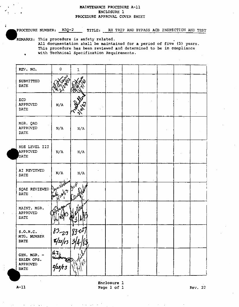
8.3 The Senior Shift Supervisor and the Senior I & C Supervisor have been notified that work will be performed on Reactor Trip Breaker or Reactor Trip Bypass Breaker.
NOTE
IF WORK IS BEING PERFORMED ON A REACTOR TRIP BREAKER GO TO STEP 8.4.
IF WORK IS BEING PERFORMED ON A REACTOR TRIP BYPASS BREAKER PROCEED TO STEP 9.0.
8.4 Enter "As Found" Serial Numbers of Reactor Trip and Bypass Breakers on Enclosure BA.
8.5 Notify Senior I & C Supervisor that there will be Maintenance performed on Reactor Trip Breaker and that the Reactor Trip Bypass Breaker
---- will be installed in Reactor Trip Breaker position.
NOTE:
WHEN TESTING REACTOR TRIP BREAKER A, INSTALL REACTOR BYPASS BREAKER B IN THE TEACTOR TRIP BREAKER A POSITION.
WHEN TESTING REACTOR TRIP BREAKER B, INSTALL REACTOR BYPASS BREAKER A IN THE REACTOR TRIP BREAKER B POSITION.
8.6 SUPERVISO/WITNESS
INSPECTION HOLD POINT
After removal of Reactor Trip Breaker. and transfer of React.or Bypass Breaker to Reactor Trip Position , notify I & C Supervisor of transfer. Do not proceed until I & C has notified Maintenance that the transferred Bypass Breaker to the Reactor Trip position has been tested and is satisfactory.
9.0 PROCEDURE
M3Q-2
NOTE:
THE STEPS IN THIS PROCEDURE NEED NOT BE DONE IN ORDER. SEQUENCING OF STEPS WILL BE DETERMINED BY THE COGNIZANT SUPERVISOR.
ACB Serial No.
NOTE:
ENCLOSURE EIGHT (8) WILL BE USED TO RECORD ANY CHANGE IN BREAKER POSITION FROM THE NORMAL POSITION INDICATED ON ENCLOSURE TWO (2).
Page 3 of 23 Rev. 2
(SW)
(IHP)

M3Q-2
9.1 Prior to making any adjustments or checks, perform the following:
9.1.1 Remove the arc chutes.
9.1.2 Check all nuts, washers, bolts, cotter pins and terminal connections for tightness. Notify Supervisor fo deficient conditions.
9.1.3 Inspect all wiring to make sure no damage has resulted during operation, if damage is evident notify Supervisor.
9.1.4 Clean and check the tightness of the control circuit stabs.
9.1.5 Thoroughly clean the equipment, removing all dust and other accumulations using brushes, wipers and vacuum cleaner.
9.2 CONTACTS
9.2.1 SUPERVISOR/WITNESS
ACRING CONTACTS
Inspect the Arcing Contacts for rough or high spots. If necessary, remove with a file or emery paper. Determine if contacts should be replaced. If replacement required, proceed to Step 9.2.1.1, if not proceed to Step 9.3. Remove any filings with a vacuum.
REMARKS:
9.2.1.1 If replacement of the Arcing Contact is required proceed as follows:
9.2.1.1.1 Open the breaker.
9.2.1.1.2 Remove the Stationary Arcing Contacts.
9.2.1.1.3 Remove the moving Arcing Contacts.
9.2.1.1.4 Install new moving Arc Contacts.
9.2.1.1.5 Install new Stationary Arcing Contacts.
Page 4 of 23
9.1.1
9.1.2
9 .1. 3
9 .1.4
9.1.5
(SW)
9.2.1.1.l
9.2.1.l.2
9.2.1.l.3
9. 2. l.1.4
9.2.1.l.5
Rev. 2

M3Q-2
9.2.2 MAIN CONTACTS
9.2.2.1 SUPERVISOR/WITNESS
Visually inspect the mating surfaces of the moveabie and stationary contacts for any. · evidence of pitting or corrosion.
NOTE:
IF THE MAIN CONTACTS SHOW EVIDENCE OF PITTING OR BURNING CONTACT WESTINGHOUSE NUCLEAR SERVICE DIVISION AND PUBLIC SERVICE NUCLEAR ENGINEERING DEPARTMENT FOR FURTHER EVALUATION.
9.2.3 ARCING CONTAcr ADJUSTMENT
SUPERVISOR/WITNESS
INSPECTION HOLD POINT
The DB-50 Arcing Contacts should touch first on closing, open last on opening. Contact pressure on the Mains is maintained by adjusting gap G to be .050 - .093 inches. (See Enclosure #1). Energize the Undervoltage Trip Coil with 43 + 2 VDC by connecting 43 VDC source to control stabs #ll and #12, then close the breaker.
If adjustment of contact gap is not necessary, open the breaker and proceed.to Step 9.2.4. If adjustment is necessary, proceed to Step 9.2.3.1.
REMARKS:
9.2.3.1 Perform contact adjustment as follows:
9.2.3.1.1 Adjust the contact gap by opening the breaker and removing the crossbar, then screwing the insulating link in or out on the stud. Be sure to tighten the lock nuts after each adjustment. Record "As Left" contact gap on Enclosure 7.
NOTE:
TO INCREASE THE GAP TURN INSULATING LINK COUNTER CLOCKWISE. TO DECREASE
(SW)
9.2.2.l
(SW)
(IHP)
THE GAP TURN INSULATING LINK CLOCKWISE. 1/2 TURN CHANGES THE GAP BY APPROXIMATELY .010 TO .015 INCHES.
Page 5 of 23 Rev. 2

•
M3Q-2
9.2.4 SUPERVISOR/WITNESS
INSPECTION HOLD POINT
CAUTION:
DO NOT OVERADJUST AS THIS WILL CAUSE THE CONTACT SPRINGS TO COMPRESS TO THE SOLID POSITION AND THUS INCREASE THE CLOSING EFFORT. CHECK FOR OVER ADJUSTMENT BY PRYING THE STATIONARY ARC TIPS OPEN TO AT LEAST 1/16 INCH GAP. IF CORRECT G GAP CANNOT BE OBTAINED BY THE ADJUSTMENT STATED, CONTACT WESTINGHOUSE ELECTRIC NUCLEAR SERVICES DIVISION AND PUBLIC SERVICE NUCLEAR ENGINEEF1NG DEPARTMENT.
Replace the arc chutes, close breaker and measure resistance to breaker frame and phase to phase using a calibrated me9gar. Record adjustments on Enclosure 7.
REMARKS:
9.3 OPERATING MECHANISM
(SW)
(IHP)
9.2.4
The operating mechanism (See Enclosure 1) is non-adjustable and consists of a series of non-ferrous links designed to secure low closing and tripping forces. To check for friction, raise the trip bar and slowly rotate the manual operating handle in "close" direction. The linkage should follow the handle without sticking. Inspect linkage for excessive wear, cracks or signs of stress. Notify Supervisor immediately of discrepancies found.
9.4 CLOSING COIL
SUPERVISOR/WITNESS
The closing coil (Enclosure 3), is non-adjustable. It is designed for intermi'ttent duty only. Inspect connections, and check for loose bolts. If it is necessary to replace the coil, proceed to Step 9.4.l.
REMARKS:
Page 6 of 23 Rev. 2
9.3
(SW)
9.4

•
•
M3Q-2
9.4.1 To remove/replace the coil:
9.4.1.1 Trip breaker
9.4.1.2 Disconnect closing coil leads from control circuit wiring. One Coil wire (Large Black) is on the top left terminal of the Control Relay. The other Coil Wire (Large Black) is on the bottom 4 Pole Auxiliary Switch located on the third (3rd) bottom terminal from the left.
9.4.1.3 Remove the bolts (9), washers (12), relay release arm (8), bolts (10), washers (11), and plate (2).
9.4.1.4 Drop closing coil (7) with brass tube (5).
9.4.1.5 Replace closing coil. Be sure to replace brass tube (5) so that the stationary core (4) and moving core (3) are aligned in the tube.
9.4.1.6 Reinstall plate (2), washers (11), bolts (10), relay release arm (8), washers (12), and bolts (9).
9.4.1.7 Reconnect closing coil leads. One Coil Wire (Large Black) is on the top left terminal of the Control Relay. The other Coil Wire (Large Black) is on the bottom 4 Pole Auxiliary Switch located on the Third (3rd) bottom terminal from the left.
9.4.1.8 Manually rotate operating handle in close direction with trip lever down to verify solenoid operates smoothly without binding.
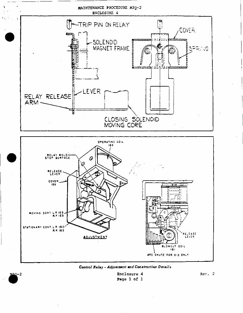
9.5 CONTROL RELAY
The control relay (See Enclosure 4) mounts directly under the auxiliary switch. It is a single-coil, mechanically-tripped device with the coil suitable for continuous energization. The operation sequence is outlined in Public Service Drawing Number 203646. The contacts should normally last the life of the breaker, but are replaceable if found necessary. Inspect contacts for visible sign of stress or arcing.
Page 7 of 23
9.4.1.1
9.4.1.2
9.4.1.3
9.4.1.4
9.4.l.5
9.4.1.6
9.4.1.7
9.4.1.8
9.5
Rev. 2

•
•
• M3Q-2
9.5.1 The relay trip assembly may be checked for correct operation of the realy and the relay release arm as follows:
9.5.1.1 Disconnect the closing coil leads from the control circuit wiring. One Coil Wire (Large Black) is on the top left terminal of the Control Relay. The other Coil Wire (Large Black) is on the bottom 4 Pole Auxiliary Switch located on the Third (3rd) bottom terminal from the left. Refer to Public Service Drawing Number 203646.
9.5.1.2 Energize relay operating coil with 125VDC.
9.5.1.3 Block the Undervoltage Trip Attachment by applying 43 ±. 2 VDC to the Coil as. follows:
9.5.1.3.l Connect a variable DC power supply t_o a two pole test switch assuring the power supply is de-energized and the variable potentiometer is turned to the lowest position.
9.5.1.3.2 Connect a fluke voltmeter to the line side of the test switch •
9.5.1.3.3 Connect the load side of the test switch to breaker control stabs #11 and #12.
SUPERVISOR/WITNESS
INSPECTION HOLD POINT
9.5.1.3.4 With the test switch in the open position, energize the power supply. Adjust the variable potentiometer until the fluke reads 43 + 2 Volts.
9.5.1.3.5 Close the test switch and recheck the power supply. If voltage drops below 43 +·2 VDC, readjust to proper level •
9.5.1.1
9.5.1.2
9.5.1.3.l
9.5.1.3.2
9.5.1.3.3
(SW)
(IHP)
9.5.1.3.4
_J 9.5.1.3.5
Page 8 of 23 Rev. 2
•
•
• M3Q-2
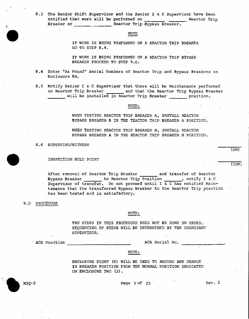
9.5.1.4 SUPERVISOR/WITNESS
Slowly close the breaker manually. The relay release arm should operate the relay trip assembly and the relay trip assembly should open the relay contacts just before the breaker latches. This position can best be determined by watching the pawl in the breaker operating mechanism, which should snap in place just after the relay contacts open. If operation is satisfactory, proceed to Step 9.5.1.6.
9.5.1.5 SUPERVISOR/WITNESS
If this operation sequence is not satisfactory, the relay release arm should be adjusted to suit. Contact Westinghouse Electric Nuclear Services Division to perform further inspection and adjustment if required.
9.5.1.6 When the breaker is latched, de-energizing and then energizing the relay operating coil should not cause the relay contacts to move toward the closed position. Trip breaker by slowly releasing the Undervoltage Trip Attachment Lever Arm.
CAUTION
ENSURE BREAKER TRIPS BEFORE PROCEEDING.
9.5.1.7 Reconnect closing coil leads to the control circuit wiring. One Coil Wire (Large Black) is on the top left terminal of the Control Relay. The other Coil Wire (Large Black) is on the bottom 4 Pole auxiliary switch located on the Third (3rd) bottom terminal from the left. Check electric closing of breaker.
9.5.1.B De-energize the temporary supply voltage to the Undervoltage Trip Attachment Coil.
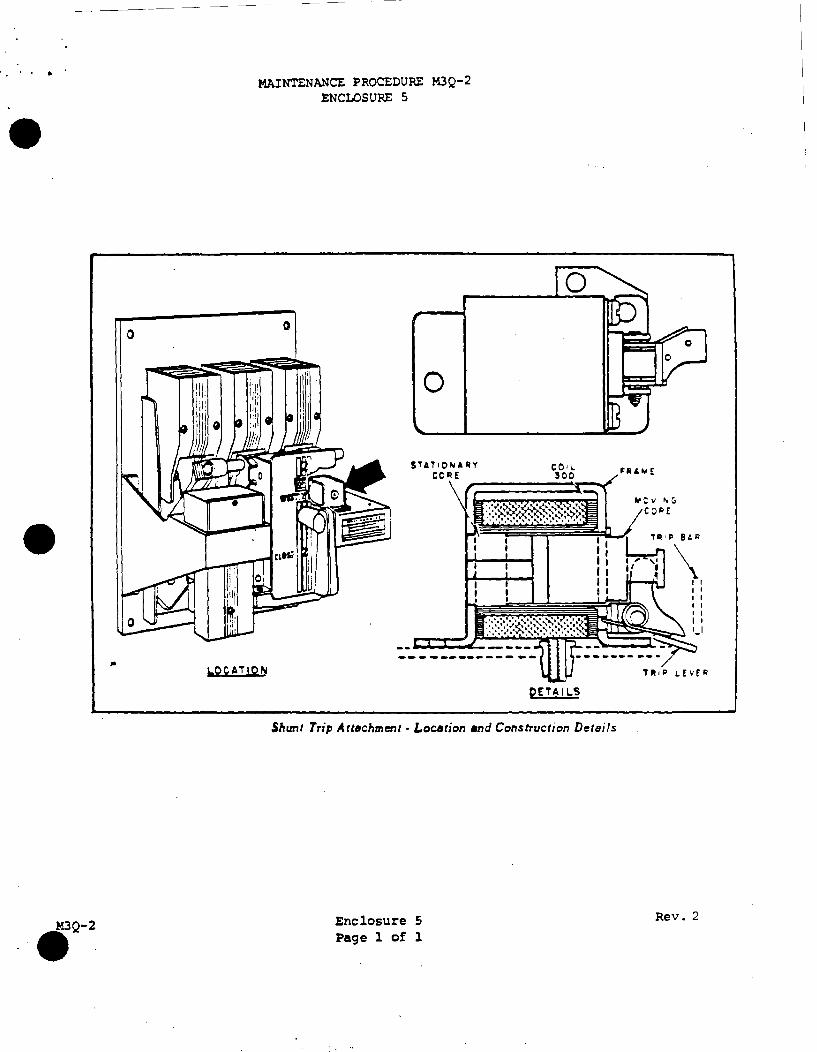
9.6 SHUNT TRIP
The shunt trip mounts on top of the platform immediately to the right of the operating mechanism. (See Enclosure 5).
It is non-adjustable and is intended for intermittent duty only. The shunt trip circuit must always be opened by an auxiliary switch contact •
(SW)
9.5.1.4
(SW)
9.5.1.5
9.5.l.6
9.5.1.7
9.5.1.B
Page 9 of 23 Rev. 2

•
•
9.7
• M3Q-2
9.6.l Inspection
9.6.1.1 Energize the Undervoltage Trip Attachment Coil via the test switch that was installed in Step 9.5.1.3.
9.6.l.2 SUPERVISOR/WITNESS
INSPECTION HOLD POINT
With the breaker in the open position, manually push the moving core against the stationary core and rotate the breaker handle to the closed position. The breaker should be trip free.
9.6.1.3 The trip lever of the shunt trip should have from 1/32 to 1/8 inch clearance to the trip bar. Record setting on Enclosure 7. If setting is out of specification, notify Supervisor.
9.6.l.4 Remove covers from the auxiliary contact blocks and visually examine contacts for evidence of arcing. Visually examine the wiring for fraying and check all terminals for tightness.
9.6.l.5 Reinstall the auxiliary contact block covers • Be sure that the upper block cover is installed properly. It has a full top cover lip whereas the other two cover lips are notched for wiring purposes.
9.6.1.6 Check for loose bolts. Manually close the breaker and check for faulty coil by checking continuity through coil and auxiliary contact with a fluke meter, reading between control stabs 3 and 7 (See Public Service Drawing 203646). Record on Enclosure
9.6.1.l
(SW)
(IHP)
9.6.1.2
9.6.1.3
9.6.1.4
9.6.1.5
7. 9.6.l.6
9.6.l.7 Manually trip the breaker.
9.6.1.8 De-energize the temporary supply voltage to the Undervoltage Trip Attachment Coil and disconnect the leads from the breaker stabs #11 and #12.
Undervoltage Trip Attachment
The Undervoltage Trip mounts on top of the platform, to the right of the shunt trip. (See Enclosure 6). Its function is to trip the breaker when the voltage falls to between 30 to 60 percent of normal.
9.6.1.7
9.6.1.8
Page 10 of 23 Rev. 2
j

•
• M3Q-2
The moving core is normally held magnetically against the stationary core to hold the Micarta rod and consequently the reset lever, in the reset position.
When the coil voltage is reduced sufficiently, the reset lever spring overcomes the magnetic attraction of the cores and rotates the reset lever clockwise. As the reset lever rotates, it carries with it the latch pin which rotates relative to the latch until the latch is released. When the latch releases, the trip spring rotates the trip lever counterclockwise to trip the breaker. The latch is reset by the cross bar moving the adjustable reset lever as the breaker opens. Enclosure 6 shows the cross bar in the open position of the br'eaker.
CAUTION
THE SELF-LOCKING SCREW (REFER TO ENCLOSURE #6) IN THE MOVING CORE IS SET AT THE FACTORY AND SHALL NOT BE ADJUSTED IN THE FIELD. IT IS USED TO SECURE THE LATCH RELEASE WHEN THE MOVING CORE IS 7/32 OUTSIDE THE FRAME. THE UNDERVOLTAGE TRIP ATTACHMENT COIL VOLTAGE DROP OUT ADJUSTMENT IS MADE AT THE FACTORY. THIS ADJUSTMENT SCREW IS NOT TO BE TAMPERED WITH IN THE FIELD. DO NOT ATTEMPT TO MAKE ANY FIELD ADJUSTMENTS ON THIS SCREW.
9.7.1 Perform a visual inspection of the Undervoltage Trip, check for loose mounting bolts, and check coil continuity using a Fluke Meter. Read between terminals 11 and 12. Record on Enclosure 7.
9.7.2 Lubrication of the Undervoltage Trip Attachment •
9.7.2.l SUPERVISOR/WITNESS
INSPECTION HOLD POINT
Inspect Undervoltage Trip Attachment for accumulations of dust and debris. Clean mechanism with Stoddard solvent,
9.7.2.2 Lubricants
SUPERVISOR/WITNESS
INSPECTION HOLD POINT
Although the Instruction Manual (page 5) cautions against any relubrication in the field, the manufacturers have agreed that the reliability of the breaker is improved by lightly lubricating
9.7.1
(SW)
(IHP)
9.7.2.l
(SW)
(IHP)
Page 11 of 23 Rev. 2

•
•
••
9.7.2.2 (Con't) the linkage of the Undervoltage device.
9.7.3
Undervoltage Trip Attachment lubricant should be mixture of five parts lubricating grade molybdenum disulfide with two parts of commercial grade isopropyl alcohol. Points of lubrication are: {l) pin running through the trip spring, {2) loop end of the latch, {3) latch pin. Apply as single drop where above parts come in contact with another metal part.
SUPERVISOR/WITNESS
INSPECTION HOLD POINT
UNDERVOLTAGE TRIP ATTACHMENT COIL TEST
With the Undervoltage Attachment remaining de-energized, operate the breaker by means of the manual lever, and confirm that the breaker trips "free" (Open) on closing motion.
9.7.3.1 Connect a variable DC power supply to a 2 Pole test switch assuring the power supply is deenergized and the variable potentiometer is turned to the lowest position.
9.7.3.2 Connect a fluke volt meter to the line side of the test switch •
9.7.3.3 Connect the load side of the test switch to breaker control stabs #11 and #12.
9.7.3.4 SUPERVISOR/WITNESS
INSPECTION HOLD POINT
With the test switch in the open position energize the power supply. Adjust the variable potentiometer until the fluke reads 43 + 2 Volts.
9.7.3.5 SUPERVISOR/WITNESS
INSPECTION HOLD POINT
Close the test switch and recheck the power supply. If voltage drops below 43 .±.. 2 VDC, readjust to proper level. Verify Undervoltage Coil latches the trip mechanism by moving the breaker toward the closed position with the manual lever. The Undervoltage Trip Attachment lever will stop following the connection arm with the breaker approximately 1/3 to 1/2 travel toward the closed position.
9.7.2.2
(SW)
(IHP)
9.7.3
(SW)
(IHP)
9.7.3.4
(SW)
(IHP)
9.7.3.5
M3Q-2 Page 12 of 23 Rev. 2
I .

•
•
• M3Q-2
9.7.3.6 Manually close the breaker.
9.7.3.6.l Measure gap between Undervoltage Trip Lever and breaker trip bar and record on Enclosure 7.
9.7.3.7 SUPERVISOR/WITNESS
9.7.3.8
9.7.3.9
9.7.3.10
INSPECTION HOLD POINT
Open the test switch. Verify that the Undervoltage Relay drops out and trips the breaker. If the breaker does not trip proceed to Step 9.7.4.
Manually close the breaker.
Slowly turn the variable.Potentiometer to decrease the voltage. Monitor the voltage level and document level obtained to trip the breaker open. (See Enclosure 7). (Undervoltage Trip Attachment Coil Dropout Voltage).
De-energize the test equipment and remove all test equipment.
NOTE:
IF THE UNDERVOLTAGE TRIP ATTACHMENT ON THE REACTOR TRIP OR REACTOR TRIP BYPASS BREAKERS IS REQUIRED TO BE REPLACED 1 THE FOLLOWING PROCEDURE WILL BE USED.
9.7.4 UNDERVOLTAGE TRIP ATTACHMENT REPLACEMENT PROCEDURE
NOTE:
REFER TO CAUTION UNDER SECTION 9.7 BEFORE PROCEEDING.
9.7.4.l SUPERVISOR/WITNESS
INSPECTION HOLD POINT
Verify that an Undervoltage Trip Attachment, meeting Quality Control requirements is available.
9.7.4.2 Confirm that the breaker is in the tr1pped position.
Page 13- of 23
9.7.3.6.1
((SW)
(IHP)
(SW)
(IHP)
9.7.4.1
9.7.4.2
Rev. 2
••
•
••• M3Q-2
9.7.4.3 Remove the Arc Chutes from the center and right side (as viewed from outside) poles.
9.7.4.4 Separate the Undervoltage Coil leads at the in-line connection beneath the platform.
9.7.4.5 Remove the two mounting screws, and take away the original Undervoltage Attachment.
9.7.4.6 Install the new Undervoltage Attachment in place, making certain that the "Trip Lever" does not bind with, and is beneath, the breaker "Trip Bar." Bolt in place with the original· mounting hardware.
9.7.4.7 Run the coil lead via the same grommet and routing as the original coil, and reconnect to leads beneath the platform. Either polarity is satisfactory. Confirm electrical continuity by means of a multimeter check at terminals 11 and 12.
9.7.4.8 The Undervoltage Attachment will be shipped with reset adjustment all "OUt" (i.e. minimum space between the fixed and movable reset arms), and therefore should remain in the TRIPPED condition with the breaker fully open. However, a false RESET usually occurs during the installation and mounting process. Therefore, the initial step is to cycle the Undervoltage Attachment by manually moving the breaker toward the closed position to allow the Undervoltage Attachment to trip.
NOTE.:
FOR FINITE OBSERVATION OF UNDERVOLTAGE OPERATION, BREAKER OPERATION IS OBTAINED BY MANUALLY PUSHING THE· CENTER "MOVING ARCING CONTACT" IN A SLOW BUT CONTINUOUS MOTION. PUSHING ON ONE OF THE SIDE CONTACTS IS NOT ACCEPTABLE, AS THERE MAY BE SOME UNDESIRABLE COCKING OF THE MOVING ASSEMBLY, AND OPERATION BY THE "LEVER HANDLE" IS NOT ACCEPTABLE BECAUSE THE RAPID MOVEMENT AND OVER TRAVEL SHOCK DO NOT PROVIDE A CRITICAL CHECK.
9.7.4.8.l SUPERVISOR/WITNESS
INSPECTION HOLD POINT
Page 14 of 23
9.7.4.3
9.7.4.4
9.7.4.5
9.7.4.6
9.7.4.7
9.7.4.8
(SW)
(IHP)
Rev. 2
•
•
• M3Q-2
With the Undervoltage de-energized, and the breaker toward the closed position, confirm that the Undervoltage Attachment is in the TRIPPED condition as indicated by zero clearance between the "Trip Lever" and "Trip Bar." (The "Trip Lever" will actually be suspending the "Trip Bar" about 1/4 inch) •
9.7.4.9 SUPERVISOR/WITNESS
INSPECTION HOLD POINT
Confirm that the "Reset Lever" pivot/lock screw is sufficiently loose to permit movement between the fixed and movable "Reset Arms"; and loosen the locknut on the "Reset Lever" adjust screw.
9.7.4.10 SUPERVISOR/WITNESS
INSPECTION HOLD POINT
Slowly increase the "Reset Lever Adjustment" by turning the screw clockwise until RESET occurs. On initial adjustment, as much as 10 to 20 turns of the screw may be required. RESET action will be indicated by an audible click, slight dropping of the "Trip Lever" and "Trip Bar"-, and raising of the "Trip Latch."
9.7.4.11 SUPERVISOR/WITNESS
INSPECTION HOLD POINT
After RESET action has occurred in Step 9.7.4.10, turn the "Reset Adjust Screw" one additional turn. Then relock the adjust screw and the pivot/lock screw.
9.7.4.12 SUPERVISOR/WITNESS
INSPECTION HOLD POINT
Move the breaker toward the closed position until a TRIP occurs as denoted by a readily audible click, dropping of the "latch", and kick-out of the "Trip Lever".
Page 15 of 23
9.7.4.B.1
(SW)
(IHP)
9.7.4.9
(SW)
(IHP)
9.7.4.10
(SW)
(IHP)
9.7.4.11
(SW)
(IHP)
9.7.4.12
Rev. 2

•
•
• M3Q-2
-------- ----- -------- - -
9.7.4.13 SUPERVISOR/WITNESS
INSPECTION HOLD POINT
Allow the moving assemble to move slowly toward the open position and confirm that RESET occurs just as the moving assemble comes to ~·. (See Step 9.7.4.10).
9.7.4.14 SUPERVISOR/WITNESS
INSPECTION HOLD POINT
Repeat Steps 9.7.4.12 and 9.7.4.13 a sufficient number of times to be assured that TRIP action (on closing motion) and RESET action (just as the moving assembly comes to rest on opening motion) are correct. If, however, there are any malfunctions or questionable actions, re-adjust the "Reset Lever" and repeat Steps 9.7.4.9 through 9.7.4.13.
9.7.4.15 SUPERVISOR/WITNESS
INSPECTION HOLD POINT
UNDERVOLTAGE TRIP ATTACHMENT COIL TEST
With the Undervoltage Attachment remaining de-energized, operate the breaker by means of the manual lever, and confirm that the breaker trips "free" (Open) on closing motion.
9.7.4.16 Measure the gap between the Undervoltage Trip Lever and the Breaker Trip Bar. Record on Enclosure 7.
9.7.4.17 Connect a variable DC power supply to a two pole test switch assuring the power supply is de-energized and the variable potentiometer is turned to the lowest position.
9.7.4.18 Connect a fluke volt meter to the line side of the test switch.
9.7.4.19 Connect the load side of the test switch to breaker control stabs #11 and #12 •
Page 16 of 23
(S'lv)
(IHP)
9.7.4.13
(SW)
(IHP)
9.7.4.14
(SW)
(IHP)
9.7.4.16
9.7.4.17
9.7.4.18
9.7.4.19
Rev. 2

•
•
••• M3Q-2
9.7.4.20 SUPERVISOR/WITNESS
INSPECTION HOLD POINT
With the test switch in the open position·, energize the power supply. Adjust the variable potentiometer until the fluke reads 43 + 2 Volts.
9.7.4.21 SUPERVISOR/WITNESS
INSPECTION HOLD POINT
Close the test switch and recheck the power supply. If voltage drops below 43 ±.. 2 Volts, readjust to proper level. Verify Undervoltage Coil latches the trip mechanism by moving the breaker toward the closed position with the manual lever. The Undervoltage Trip Attachment Lever will stop following the connecting arm with the breaker approximately 1/3 to 1/2 travel toward the closed position.
9.7.4.22 Manually close the breaker.
9.7.4.23 SUPERVISOR/WITNESS
INSPECTION HOLD POINT
Open the test switch. Verify that the Undervoltage Relay drops out and trips the breaker.
9.7.4.24 SUPERVISOR/WITNESS
INSPECTION HOLD POINT
Reclose the 43 VDC test switch. Reclose the breaker. Wais a minimum of thirty (30) minutes, then open the 43 VDC test switch. Verify that the breaker trips. Repeat this Step ten (10) times and record on Enclosure 9.
Page 17 of 23
(SW)
(IHP)
9.7.4.20
(SW)
(IHP)
9.7.4.21
9.7.4.22
(SW)
(IHP)
9.7.4.23
(SW)
(IHP)
9.7.4.24
Rev. 2

•
•
• M3Q-2
9.7.4.25 Close the test switch. Verify 43 + 2 VDC.
9.7.4.26 Manually close the breaker. Slowly turn the variable potentiometer to decrease the voltage.
9.7.4.27 SUPERVISOR/WITNESS
INSPECTION HOLD POINT
Monitor the voltage level and document on Enclosure 7 the voltage level obtained to trip the breaker open (Undervoltage Trip Attachment Coil drop out voltage).
9.7.4.28 De-energize the test equipment and remove all test leads.
9.8 CIRCUIT BREAKER TIMING
9.8.1 Ensure calibration of the visicorder timing lines as follows:
9.8.1.l Set TIMER MODE switch to MANUAL .
9.8.1.2 Depress 1.0 TIMER SEC. pushbutton.
9.8.1.3 Run Visicorder at 10 IPS.
NOTE:
ALLOW SUFFICIENT PAPER TO SPILL FROM VI SI CORDER TO VERIFY NEXT MEASUREMENT.
9.8.1.4 Verify time lines are spaced 10 inches apart on paper.
9.8.1.5 Adjust A8B20, as necessary to obtain a 10 inch measurement.
9.8.1.6 Depress 10.0 timer SEC. pushbutton.
9.8.1.7 Run Visicorder at 1.0 IPS.
Page 18 of 23
9.7.4.25
9.7.4.26
(SW)
(IHP)
_J 9.7.4.27
9.7.4.28
9.8.1
9.8.1.l
9.8.1.2
9.8.1.3
9.8.1.4
9.8.1.5
9.8.1.6
9.8.1.7
Rev. 2

••
•
·.:. M3Q-2
NOTE:
ALLOW SUFFICIENT PAPER TO SPILL FROM VISICORDER TO VERIFY NEXT MEASUREMENT.
9.8.1.8 Verify time lines are spaced 10 inches apart on paper. 9.8.1.8
9.8.1.9 Adjust A8Rl7 as necessary, to obtain a 10 inch measurement. 9.B.1.9
9.8.2 Position the Honeywell Visicorder, Model 1508B (M-35) and the portable Honeywell Semi-Automatic Circuit Breaker Test System (M-36) near the test station.
9.8.3 Visicorder (M-35) and Circuit Breaker Test System (M-36) set up.
9.8.3.1 Attach the interconnecting cables between the circuit breaker test system (M-36), and the Visicorder (M-35) as follows: (Refer to Enclosure 8).
CABLE FUNCTION
FROM (M-36) TEST SYSTEM
TO (M-35) VIS I CORDER
Galva Channels 13-18 J-13
9.8.3.2 Ensure all switches are in OFF position.
AlOJl
9.8.3.3 Connect 115 VAC power to control box (M-36).
9.8.4 Visicorder Set-Up:
9.8.4.l TIMER MODE in OFF position, POWER/LAMP pushbutton in the OUT position.
9.8.4.2 Connect test leads to J6 and J7 jacks in rear of (M-36) test set.
9.8.4.3 Connect 3 bottom breaker main stabs together with braid material. Connect black leads of test cables coming from J6 and J7 to braid.
NOTE:
RED WIRE OF TEST CABLE FROM J6 IS SPARE.
9.8.4.4 Connect red and white wires of test cable from J7 and white wire of test cable from J6 to three (3) top main stabs of breaker.
Page 19 of 23 :Rev. 2
9.8.2
9.8.3
9.8.3.1
9.8.3.2
9.B.3.3
9.8.4
9.B.4.1
9.8.4.2
9.8.4.3
9.8.4.4

•
•
• M3Q-2
9.8.4.5 Connect test leads of DC amplified #2 (Pair #2) to load side of 43V test switch.
9.8.5 Locate and identify each spot on the recording paper.
NOTE:
ADJUST GALVANOMETER VERTICALLY AND HORIZONTALLY AS REQUIRED TO BRING LIGHT SPOT INTO VIEW FOR IDENTIFICATION. (ENCLOSURE 6).
9.8.6 Galvanometer vertical adjustment:
9.8.7
9.8.6.l Insert manufacturer supplied adjustment tool or a small screwdriver in the vertical adjusting screw located behind each galvanometer.
9.8.6.2 Turn adjusting screw slowly, as required, to locate the light spot on the recording plane of the paper.
NOTE:
THE VERTICAL ADJUSTMENT WILL TILT THE GALVANOMETER EITHER FORWARD OR BACKWARD IN ORDER TO BRING THE LIGHT SPOT INTO FOCUS ON THE RECORDING PAPER.
Galvanometer horizontal adjustment:
9.8.7.1 Using the blade with central key portion of the adjusting tool, insert adjusting tool in horizontal adjusting slot.
9.B.7.2 Turn adjusting screw slowly, as required, to locate the light spot on the recording plane of the paper.
9.8.7.3 Ensure light beams are pointing straight ahead and not crossing one another.
9.8.7.4 Use the calibrated scale to position the light spots.
NOTE:
REFERENCE ENCLOSURE(S) 6 AND 7
9.8.8 Set contact current galvanometers on Channels 13, 14 & 15 •
Page 20 of 23
9.8.4.5
9.8.5
9.8.6
9.8.6.l
9.8.6.2
9.8.7
::J 9.8.7.2
I 9.8.7.3
I 9.8.7.4
9.8.8
Rev. 2

•
•
• M3Q-2
9.8.9 Contact current Switch Setting:
9.B.9.1 For breaker contacts with either 0 Ohms resistance or approximately 100 Ohms in a resistor switch, set on HI.
9.B.9.2 For breaker contacts with approximately 200 Ohms in a resistor switch, set on LO.
9.B.10 Observe galvanometer deflections of contact current channels.
9.8.11 SUPERVISOR/WITNESS
INSPECTION HOLD POINT
BREAKER CLOSE/OPEN TEST
9.8.11.1 Verify ready light is lit.
9.8.11.2 Verify the breaker to be tested is open.
9.8.11.3 Verify the Undervoltage Coil is de-energized.
9.B.11.4 Energize the Undervoltage Coil by closing two (2) pole test switch.
9.8.11.5 Manually close breaker.
9.8.11.6 Start Visicorder.
9.8.11. 7 Open two (2) pole test switch.
9.9 SUPERVISOR/WITNESS
INSPECTION HOLD POINT
VISICORDER TRACE
9.9.l Ensure trace data was obtained.
Page 21 of 23
9.B.9
9.8.9.l
I 9.B.9.2
9.B.10 I
(SW) I I
(IHP)
9. 8 .11..l
9.8.11.2
9 .8 .11.3
9.B.11.4
9. B .11. 5
9.B.11.6
9.8.11.6
(SW)
(IHP)
9.9.l
Rev. 2

•
•
• M3Q-2
9.9.2 Identify each trace.
9.9.3 Record the following information on each trace:
9.9.4
1. Breaker serial number (S/N) and position. 2. Visicorder Speed (60 IN/SEC.). 3. Timing Frequency (1000 Hz). 4. Indicate paper direction. 5. Timing Line Period (0.01 SEC.). 6. Procedure number M3Q-2. 7. Date. B. Electrician's Signature. 9. Opening Time.
10. QA Record - Retain for Five Years.
NOTE:
TO DETERMINE OPENING AND CLOSING TIME, COUNT THE NUMBER OF TIMING LINES AND 1000 Hz PEAKS BETWEEN THE POINTS WHERE THE CLOSING/OPENING COIL CURRENTS START TO INCREASE, TO THE POINTS WHERE THE CONTACTS CHANGE STATE. MEASURE ON THE VISICORDER TRACE THE DISTANCE BETWEEN COIL DROP OUT TRACE TO THE LONGEST CONTACT OPENING TRACE. RECORD ON ENCLOSURE 7. ONE INCH IS EQUAL TO ONE CYCLE, THEREFORE, MEASURE TO THE NEAREST 1/16 OF INCH AND DOCUMENT IN 1/16 OF CYCLES.
SUPERVISOR/WITNESS
INSPECTION HOLD POINT
Complete Enclosure 7. Verify time is within
9.9.2
9.9.3
(SW)
(IHP)
given specification. 9.9.4
9.10 BREAKER CLOSURE TIMING TEST
9.10.l Disc Visicorder leads from test switch and reclose 43V test switch.
9.10.2 Reconnect Visicorder leads to 125VDC source and adjust Visicorder. Disconnect from source and reconnect Visicorder to breaker control stabs #11 and #8.
9.10.3 Connect 125 DC source to stabs #2 and #8.
9.10.4 Start Visicorder.
Page 22 of 23 Rev. 2
9.10.l
9.10.2
9.10.3
9.10.4

•
••
9.10.5 Energize DC source.
9.10.6 Stop Visicorder.
9.10.7 Open 43V test switch. Note that Breaker trips. De-Energize 125V DC source.
9.10.B Identify Visicorder trace.
9.10.9 Complete Enclosure 7 and verify time is within given specifications.
9.10.5
9.10.6
9.10.7
9.10.B
9.10.9
10.0 FINAL TESTING
SUPERVISOR/WITNESS
INSPECTION HOLD POINT
10.l Notify the I & c Department and the Senior Shift Supervisor that Maintenance has satisfactorily completed work· on the # ------Reactor Trip Breaker or # Reactor Trip Bypass Breaker.
11.0 CLOSEOUT AND FINAL REVIEW
11.l Procedure completed: Satsifactory ---- Unsatisfactory ----11.2 Remarks:
11.3 Test performed by: Signature Date
11.4 Reviewed by: Maintenance Supervisor Date ,
Quality Assurance Date
(SW)
(IHP)
M3Q-2 Page 23 of 23 Rev. 2

·-2
HA!NTENANCE PROCEDURE M3Q-2 ENCLOSURE l
STEEL PANEL-......_ ,,~ • J
ARC CHUTE pe-so CIRCUIT BREAKER
!600 AMPERES. 600 VOLTS A·C
IOO
PUSH TRIP )17
' \ HANDLE M
•
CLOSING COil SO•
CLOSED
CLOSING SOLENOID :903
OVERCURRENT TRIPJ:IJNG DEVICE IO~
~· TRIPPED
STl.TIONARY ARCING CONTACT ,, ..
1 • LJ!:IPER $TL.JD
S:3
-TRIP SCREW S11
MOVING cot..:TACT HINGE S09
! -A
LOWER STUD SC7
~PER COl:.. TERMiNAi.. soe
OPEN (RESET)
CroH-Sectional View of T7pe DB·50 Circuit Brea/cer
Enclosure l Page l of l
Rev. 2
\

. . .
•
•
•
SERIAL NUMBERS:
124Y7268B
224Y7268B
324Y7268B
424Y7269B
MAINTENANCE PROCEDURE M3Q-2 ENCLOSURE 2
BREAKER SERIAL NUMBERS AND POSITION
124Y7269B
224Y7269B
324Y7269B
424Y7269B
NORMAL POSITIONS:
UNIT #1
UNIT #2
M3Q-2
A TRIP 124Y7269B
B TRIP 224Y7269B
A TRIP 124Y7268B
B TRIP 224Y7268B
Enclosure 2 Page 1 of l
A BY-PASS 324Y7269B
B BY-PASS 424Y7269B
A BY-PASS 324Y7268B
B BY-PASS 424Y7268B
Rev. 2

. ,, .
•
•
M3Q-2
•
MAINTENANCE PROCEDURE M.3Q-2 ENCLOSURE 3
1-.l. 1· 0 I I ' I
1.. I i o::= '""=-=-~
~
I ~
~.,
11
I: 11
I! ; 1.~, I!:!.
Closin~ Solenoid • Construction Details
Enclosure 3 Page l of l
,.
·---.---~ ..::::.
,-.i" .
'.
Rev. 2
•
•
.-2
MAINTENANCE PROCEDURE M3Q-2 ENCLOSURE -'
(p--TRIP PIN ON R[LP\Y
r·-i cove.~
RELAY RELEASE ARM
RHAY lllOLO S'TOP SURFACE
llELEASE LE vE R
COYER 159
MOVING CONT L.P. 153 RP 163
STATIOp,;ARY CONT.LP. 160" R.P. 165
~SOLENOID , :·---1 MAGNET FRAME.
' 't' J_
. -7 i_ ___ ~
CLOSING SOLENOID MOVING COR'E
OPERATING COIL 166
I
.... · ..
AQJUSTMENT
BLOl'IOUT COIL 161
ARC CHUTE FOR D·C ON~Y
Control Relay - Adjuatrnent and Construction Details
Enclosure 4 Page l of l
Re'\·. 2
•
•
0
• •
M3Q-2 ·-
MAINTENANCE PROCEDURE M3Q-2 ENCLOSURE S
0
0
LOCATION
0
PETAi LS
Shunt Trip Attachment· Location and Construction Details
Enclosure 5 Page l of l
Rev. 2

•
•
•
M3Q-2 ....
MAINTENANCE PROCEDURE M3Q-2 ENCLOSURE 6
ADJUSTAI~[ RESET L[IJtR
11100
r.'ndervoltage Trip Attachment· Construction Details
Enclosure 6 Page 1 of l
Rev. 2
•
•
9.2.3
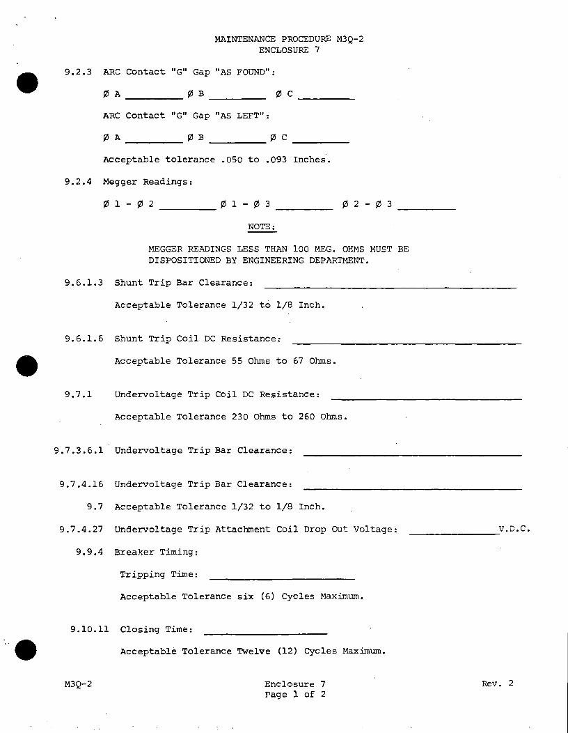
MAINTENANCE PROCEDURE M3Q-2 ENCLOSURE 7
ARC Contact "G" Gap "AS FOUND":
¢ c -----ARC Contact "G" Gap "AS LEFT":
¢A ¢B ¢ c ------ ----- -----Acceptable tolerance .050 to .093 Inches.
9.2.4 Megger Readings:
¢ 1 - ¢ 2 ____ ¢1-¢3
NOTE:
MEGGER READINGS LESS THAN 100 MEG. OHMS MUST BE DISPOSITIONED BY ENGINEERING DEPARTMENT.
9.6.l.3 Shunt Trip Bar Clearance:
Acceptable Tolerance 1/32 t6 1/8 Inch.
9.6.l.6 Shunt Trip Coil DC Resistance:
Acceptable Tolerance 55 Ohms to 67 Ohms.
9.7.1 Undervoltage Trip Coil DC Resistance:
Acceptable Tolerance 230 Ohms to 260 Ohms.
9.7.3.6.l Undervoltage Trip Bar Clearance:
9.7.4.16 Undervoltage Trip Bar Clearance:
9.7 Acceptable Tolerance 1/32 to 1/8 Inch.
9.7.4.27 Undervoltage Trip Attachment Coil Drop Out Voltage:
9.9.4 Breaker Timing:
Tripping Time:
Acceptable Tolerance six (6) Cycles Maximum.
9.10.11 Closing Time:
• Acceptable Tolerance Twelve (12) Cycles Maximum.
M3Q-2 Enclosure 7 Page l of 2
V.D.C. ---------
Rev. 2

•
•
M3Q-2
MAINTENANCE PROCEDURE M3Q-2 ENCLOSURE 7
Data Reviewed and Status:
Acceptable: Maintenance Supervisor
Unacceptable:
Any data found out of specification shall have a Deficiency Report
written against it and will be dispositioned by the Nuclear Engineering
Department. The Circuit Breaker will not be acceptable for service
until all Deficiency Reports have been satisfactorily completed.
All Deficiency Reports properly completed: / Circuit Breaker is Acceptable. Maintenance Supervisor Date
Deficiency Report Numbers:
I Quality Assurance Date
Enclosure 7 Page 2 of 2
I Quality Assurance Date
Rev. 2

' .
• UNIT #1
UNIT #2
•
Reviewed By:
M3Q-2
MAINTENANCE PROCEDURE M3Q-2 ENCLOSURE BA
BREAKER POSITION AS FOUND CONDITION
A TRIP A By-PASS
B TRIP B BY-PASS
A TRIP B BY-PASS
B TRIP B BY-PASS
Maintenance Supervisor
Quality Assurance
Page 1 of 1
I
Rev. 2

• UNIT #1
UNIT #2
•
Reviewed By:
• M3Q-2
MAINTENANCE PROCEDURE M3Q-2 ENCLOSURE BB
BREAKER POSITION AS LEFT CONDITION
' /._____A TRIP-ii [ A BY-PASS
I B TRIP l I B BY-PASS
I A TRIP
I I B BY-PASS
I B TRIP I ._____ ..___[ B B_Y-PASS _/
Maintenance Supervisor
Quality Assurance
Page 1 of 1 Rev. 2
I
r
I
I •
'.
•
•
••
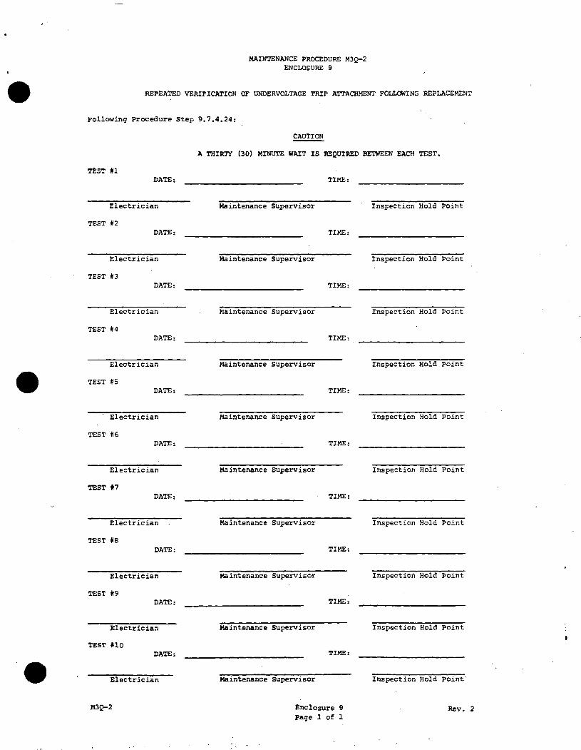
MAINTENANCE PROCEDURE M3Q-2 ENCLOSURE 9
REPEATED VERIFICATION OF UNDERVOLTAGE TRIP ATTACHMENT FOLLOWING REPLACEMENT
Following Procedure Step 9.7.4.24:
CAUTION
A THIRTY (30) MINUTE WAIT IS :REQUI:RED BETWEEN EACH TEST.
rtST #l DATE: TIME:
Electrician Maintenance Supervisor Inspection Hold Point
TEST #2 DATE: TIME:
Electrician Maintenance Supervisor Inspection Hold Point
TEST #3 DATE: TIME:
Electrician Maintenance Supervisor Inspection Hold Point
TEST #4 DATE: TIME:
Electrician Maintenance supervisor Inspection Hold Point
TEST #5 DATE: TIME:
Electrician Maintenance Supervisor Inspection Hold Point
TEST #6 DATE: TIME:
Electrician Maintenance Supervisor Inspection Hold Point
TEST #7 DATE: TIME:
Electrician Maintenance supervisor Inspection Hold Point
TEST #8 DATE: TIME:
Electrician Maintenance Supervisor Inspection Hold Point
TEST #9 DATE: TIME:
Electrician Maintenance Supervisor Inspection Hold Point
TEST #10 DATE: TIME:
Electrician Maintenance supervisor Inspection Hold Point·
M3Q-2 Enclosure 9 Rev. 2 Page l of 1