Problems Created in Attenuation-Corrected SPECT Images by...
10
Problems Created in Attenuation-Corrected SPECT Images by Artifacts in Attenuation Maps: A Simulation Study Anna Celler, PhD 1,2 ; Katherine L. Dixon, MSc 2 ; Zheng Chang, MSc 2 ; Stephan Blinder, PhD 1,2 ; John Powe, MD 1,2 ; and Ronald Harrop, PhD 1,3 1 Division of Nuclear Medicine, Vancouver Hospital and Health Sciences Centre, Vancouver, British Columbia, Canada; 2 Department of Physics and Astronomy, University of British Columbia, Vancouver, British Columbia, Canada; and 3 Department of Mathematics and School of Computing Science, Simon Fraser University, Burnaby, British Columbia, Canada The importance of accurate attenuation correction, especially for im- aging of the thorax region, is widely acknowledged. Appropriate com- pensation methods have been developed and introduced into clinical practice. Most of these methods use attenuation maps obtained using various transmission scanning systems. However, when maps are inaccurate, the correction procedure may introduce artifacts into the final images that can be difficult to identify and might inadvertently alter diagnosis and study outcome. As a result, attenuation correction is often avoided in clinical practice. Our objective was to examine issues related to the quality of attenuation maps and the effects that map artifacts may have on attenuation-corrected emission images. Methods: The topics that are investigated include the problem of low transmission counts, cross-talk contributions from the emission iso- tope, truncation of the transmission data, and methods of map re- construction and segmentation. Examples of patient studies display- ing specific problems guided our investigations, but, because truth in these studies is seldom known, analytic and Monte Carlo-simulated data were used in the analysis. Attenuation maps and final emission images were visually checked for artifacts and for the presence of perfusion defects. In addition, quantitative evaluation of map unifor- mity, defect visibility, and size variation was performed. Results: The statistical paired-sample t test showed significant ( P 0.05) improve- ment of relative SD for attenuation maps reconstructed with iterative methods as compared with filtered backprojection and for maps created with higher photon fluxes. When maps with artifacts were used to correct emission data, an increase in myocardial infarct size and creation of false heart defects were observed. Conclusion: Our study strongly recommends that at least a visual inspection of the quality of attenuation maps be performed before their use in compen- sation procedures. To improve image quality, remove artifacts, and increase diagnostic confidence, attenuation maps used in the correc- tion procedure must be accurate and free of artifacts. Key Words: SPECT; attenuation correction; transmission source; attenuation maps; image artifacts J Nucl Med 2005; 46:335–343 T he importance of accurate compensation for attenuation effects in SPECT is already widely recognized. Attenuation may lead to artifacts and inaccuracies in reconstructed im- ages, occurrences that are particularly disturbing in myo- cardial perfusion scans because of the highly nonuniform distribution of tissue in the thorax region (1–5). Several studies have demonstrated that image quality can be con- siderably improved by incorporating attenuation correction into an iterative reconstruction method (6–8). To make the correction properly, attenuation maps con- taining detailed information about density distribution in the body are required. In principle, these maps can be computed using only emission data, but this approach is still too complex and time consuming for routine use (9,10). The majority of clinical attenuation compensation techniques, therefore, use maps reconstructed from data obtained in transmission scans. Such patient-specific compensation methods, based on experimentally measured maps, should create substantially improved images, but there have been serious problems with the technique, creating distrust and leading to heated debates about the value of attenuation correction. Several reviews have shown that attenuation correction methods that are currently available on clinical cameras can introduce artifacts that may be difficult to identify and might inadvertently alter diagnoses and study outcomes (4,11). As a result, the attenuation correction option is often avoided in clinical practice, even in those centers that have all the necessary equipment. Several different transmission systems have been pro- posed, such as: (A) a single line source with symmetric (12) or asymmetric (13,14) fanbeam geometry, (B) a scanning line source with parallel-hole collimator (15), (C) a multiple line source system (16), (D) a scanning high-energy point source, and (E) a CT system operating on the SPECT camera (17). The most popular of these are B and C, with a 153 Gd source emitting 100 keV photons; system D, using a 133 Ba Received Jan. 29, 2004; revision accepted Sep. 27, 2004. For correspondence contact: Anna Celler, PhD, Division of Nuclear Medi- cine, Vancouver Hospital and Health Sciences Centre, 899 W. 12th Ave., Vancouver, British Columbia, Canada. E-mail: [email protected] ATTENUATION MAP ARTIFACTS IN SPECT • Celler et al. 335 by on June 2, 2020. For personal use only. jnm.snmjournals.org Downloaded from
Transcript of Problems Created in Attenuation-Corrected SPECT Images by...

Problems Created in Attenuation-CorrectedSPECT Images by Artifacts in Attenuation Maps:A Simulation StudyAnna Celler, PhD1,2; Katherine L. Dixon, MSc2; Zheng Chang, MSc2; Stephan Blinder, PhD1,2; John Powe, MD1,2;and Ronald Harrop, PhD1,3
1Division of Nuclear Medicine, Vancouver Hospital and Health Sciences Centre, Vancouver, British Columbia, Canada;2Department of Physics and Astronomy, University of British Columbia, Vancouver, British Columbia, Canada; and 3Department ofMathematics and School of Computing Science, Simon Fraser University, Burnaby, British Columbia, Canada
The importance of accurate attenuation correction, especially for im-aging of the thorax region, is widely acknowledged. Appropriate com-pensation methods have been developed and introduced into clinicalpractice. Most of these methods use attenuation maps obtainedusing various transmission scanning systems. However, when mapsare inaccurate, the correction procedure may introduce artifacts intothe final images that can be difficult to identify and might inadvertentlyalter diagnosis and study outcome. As a result, attenuation correctionis often avoided in clinical practice. Our objective was to examineissues related to the quality of attenuation maps and the effects thatmap artifacts may have on attenuation-corrected emission images.Methods: The topics that are investigated include the problem of lowtransmission counts, cross-talk contributions from the emission iso-tope, truncation of the transmission data, and methods of map re-construction and segmentation. Examples of patient studies display-ing specific problems guided our investigations, but, because truth inthese studies is seldom known, analytic and Monte Carlo-simulateddata were used in the analysis. Attenuation maps and final emissionimages were visually checked for artifacts and for the presence ofperfusion defects. In addition, quantitative evaluation of map unifor-mity, defect visibility, and size variation was performed. Results: Thestatistical paired-sample t test showed significant (P � 0.05) improve-ment of relative SD for attenuation maps reconstructed with iterativemethods as compared with filtered backprojection and for mapscreated with higher photon fluxes. When maps with artifacts wereused to correct emission data, an increase in myocardial infarct sizeand creation of false heart defects were observed. Conclusion: Ourstudy strongly recommends that at least a visual inspection of thequality of attenuation maps be performed before their use in compen-sation procedures. To improve image quality, remove artifacts, andincrease diagnostic confidence, attenuation maps used in the correc-tion procedure must be accurate and free of artifacts.
Key Words: SPECT; attenuation correction; transmissionsource; attenuation maps; image artifacts
J Nucl Med 2005; 46:335–343
The importance of accurate compensation for attenuationeffects in SPECT is already widely recognized. Attenuationmay lead to artifacts and inaccuracies in reconstructed im-ages, occurrences that are particularly disturbing in myo-cardial perfusion scans because of the highly nonuniformdistribution of tissue in the thorax region (1–5). Severalstudies have demonstrated that image quality can be con-siderably improved by incorporating attenuation correctioninto an iterative reconstruction method (6–8).
To make the correction properly, attenuation maps con-taining detailed information about density distribution in thebody are required. In principle, these maps can be computedusing only emission data, but this approach is still toocomplex and time consuming for routine use (9,10). Themajority of clinical attenuation compensation techniques,therefore, use maps reconstructed from data obtained intransmission scans. Such patient-specific compensationmethods, based on experimentally measured maps, shouldcreate substantially improved images, but there have beenserious problems with the technique, creating distrust andleading to heated debates about the value of attenuationcorrection. Several reviews have shown that attenuationcorrection methods that are currently available on clinicalcameras can introduce artifacts that may be difficult toidentify and might inadvertently alter diagnoses and studyoutcomes (4,11). As a result, the attenuation correctionoption is often avoided in clinical practice, even in thosecenters that have all the necessary equipment.
Several different transmission systems have been pro-posed, such as: (A) a single line source with symmetric (12)or asymmetric (13,14) fanbeam geometry, (B) a scanningline source with parallel-hole collimator (15), (C) a multipleline source system (16), (D) a scanning high-energy pointsource, and (E) a CT system operating on the SPECTcamera (17).
The most popular of these are B and C, with a 153Gdsource emitting 100 keV photons; system D, using a 133Ba
Received Jan. 29, 2004; revision accepted Sep. 27, 2004.For correspondence contact: Anna Celler, PhD, Division of Nuclear Medi-
cine, Vancouver Hospital and Health Sciences Centre, 899 W. 12th Ave.,Vancouver, British Columbia, Canada.
E-mail: [email protected]
ATTENUATION MAP ARTIFACTS IN SPECT • Celler et al. 335
by on June 2, 2020. For personal use only. jnm.snmjournals.org Downloaded from

source with 356 and 383 keV photons; and E, using a broadenergy spectrum of x-rays.
The need for strict quality control and appropriate testingprotocols for transmission systems has long been identified(2). Creation of such protocols is, however, a difficult taskbecause of the wide variety of transmission systems, eachwith its own characteristics and different calibration andcorrection requisites. For example, some systems performtransmission and emission scans in sequence, others simul-taneously. However, in both situations, scattered emissionphotons recorded in the transmission energy window (cross-talk effect) create a problem that is only reduced, noteliminated, by electronic collimation used in scanning linesystems. Some use static and others tomographic blankscans. The shapes, energies, and intensities of the transmis-sion photon beams also vary.
Regardless of the system used, the final result of thetransmission scan is an attenuation map of the patient, andthe accuracy of this map is of paramount importance for thecorrection procedure. In everyday clinical practice, themaps are seldom viewed or checked for artifacts. Additionalquality control problems arise when clinical software in-cludes other (often approximate) corrections to compensatefor such effects as scatter and collimator blurring. As aresult of applying some or all of these, the relationshipsamong the initial data, map quality, and accuracy of the finalcorrected image are quite complex. An investigation of allthese issues would be especially difficult for clinical imagesbecause of the wide range of variations in patient anatomyand lack of information about the truth.
This study focuses on the complex relationships betweenthe quality of the map and the accuracy of the attenuationcorrection and investigates the effects introduced by mapartifacts into the attenuation-corrected emission imageswithout any scatter correction. Present work is restricted toisotope-based transmission systems, and CT systems will beinvestigated in the future. We strongly believe that attenu-ation correction substantially improves the accuracy ofemission images but only when it is properly performed.Our aim is to raise users’ awareness by demonstrating thatincorrect maps may indeed produce false perfusion defects.By showing this, we want to prove the need for stricter
quality control and motivate the user to check the accuracyof the attenuation map before reading attenuation-correctedimages. We investigated the following issues: low or miss-ing counts in the transmission data, cross-talk correction forscattered emission photons, truncation of the attenuationmap, the method used for map reconstruction, and effectsrelated to the use of a segmented map.
Qualitative and quantitative analyses of attenuation mapsand of attenuation-corrected emission images were per-formed using simulations with the thorax mathematic car-diac torso (MCAT) phantom, because this approach allowedus to control the data and also to know the “truth” (18).Examples of patient attenuation maps displaying specificproblems from clinical myocardial perfusion studies wereused to guide the study and to illustrate different issues.Examples of such maps are presented in Figure 1, often withmore than a single effect contributing to the final stronglyaltered density distribution.
MATERIALS AND METHODS
Transmission Data SimulationsTransmission and blank data were created using our Analytic
Transmission Simulator (ATS) (19). This program generates 2-di-mensional (2D) transmission projections for different geometriesof the source using a density distribution map of the object andtaking into account collimator acceptance angles on the source anddetector sides. A 153Gd source was used in these simulations.Scatter of transmission photons was not simulated, because ourearlier study showed scatter to have a less than 1% contribution tothe primary events (20). Two shapes of transmission photon beamswere investigated: (A) uniform: a uniform photon flux distribution,such as that produced by a scanning line source (for example, theVantagePro system by Philips Medical Systems), and (B) profile:a parabola-like shape of the photon flux, such as that as created bya multiple-line system (for example, the Profile system by SiemensMedical Solutions).
Poisson-type noise was added to these data to model transmis-sion scans with maximum photon fluxes ranging from 200 to10,000 counts/pixel per projection. These numbers must be relatedto those observed in clinical transmission systems. A newly in-stalled set of line sources for the Siemens Profile has a totalactivity of 3,700 MBq (100 mCi), with the strongest lines mea-suring 740 MBq each. This activity produces approximately 650
FIGURE 1. Examples of patient attenua-tion maps displaying problems discussed inthis study: truncation from Beacon systemseen in posterior torso (A and B), area ofdecreased attenuation in center of thorax(C), truncation from Profile system seen aslarge variation in attenuation coefficientacross abdomen (D), appearance of “false”lungs near anterior abdominal surface (E),right lung appears as 2 lungs (“third lung”effect) (F), anterior wall of chest showing at-tenuation coefficients appreciably lower thanthose in central and posterior regions (Gand H).
336 THE JOURNAL OF NUCLEAR MEDICINE • Vol. 46 • No. 2 • February 2005
by on June 2, 2020. For personal use only. jnm.snmjournals.org Downloaded from

counts in a maximum pixel for a 20 s projection scan as used in astandard rest sestamibi heart perfusion study. The Profile sourcesystem is allowed to decay to half of its initial activity before theweakest sources are removed while the 2 central line sources arereplaced by new ones and the old sources are shifted to moreoutside positions. By the time of source exchange, counts in a 20 sscan drop to a level of 300–350 in a maximum pixel. A newlyinstalled line source in the VantagePro system has an activity of7,400 MBq (200 mCi), and, initially, absorbers are used to lowerthe intensity of the photon flux. The empirically determined countlevel produced by the new scanning line source is about 380–400counts per pixel in a 20 s projection and drops to about 200 beforethe source exchange. Therefore, the 200 and 500 count levels usedin our simulations correspond to transmission studies performedwith old and almost newly installed sources, respectively. The2,000 and 10,000 count levels correspond to high and very highstatistics modeling, which we consider as a “very good” and an“ideal” case, respectively. As will be discussed later, transmissionsystems producing such counting rates would be clinically viable.
The full range of photon flux values was used only in tests of themissing count problem. Other studies were performed for 500 and2,000 counts/pixel to model the strengths of currently availabletransmission sources and to compare with ones that almost nevercreate missing counts.
The MCAT phantom was used as the attenuator. A femalephantom was chosen to provide enhanced attenuation from breasttissue. The camera system had a 40 � 50 cm detector equippedwith a parallel-hole, high-resolution (HIRES) collimator, with theacceptance angle equal to 2.7°. The energy resolution of thedetector was assumed to be 10%, with a 3 mm intrinsic spatialresolution. The distance between the detector and the transmissionsource was set at 115 cm, and the source collimator had a 5.3°opening angle. Projections were created in a 128 � 128 matrixwith a pixel size of 0.36 cm. The simulated acquisition wasperformed using a standard 180° cardiac rotation protocol with acircular orbit, radius of rotation of 32 cm, and a total of 64projections.
In all cases except where specified, attenuation maps werereconstructed using 2 methods: filtered backprojection (FBP) andordered subsets transmission gradient (OSTG) (19). The OSTGalgorithm corresponds to a modified version of the maximumlikelihood transmission gradient (MLTG) method (21,22). TheOSTG algorithm is expressed as:
�jk�1 � �j
k
�i�Sn
�ci exp� � �m
�mk lim�lij�
�i�Sn
Tilij
, Eq. 1
where �jk�1 is the value of attenuation coefficient at pixel j ob-
tained in the k � 1 iteration step. The iteration procedure usescyclic ordering with n � k(mod(Nsub)) � 1, where the number ofsubsets Sn is equal to Nsub. The length of the intersection of the lineof response corresponding to camera bin i with pixel j is lij, and ci
and Ti are the counts measured in projection bin i in the blank andtransmission scans, respectively.
Emission Data SimulationsThe same MCAT phantom was used to model the activity
distribution in the thorax. Three different phantoms were cre-ated: with a normal heart (total volume, 152 mL) and withperfusion defects (21 mL) located in the inferior wall and the
septal wall of the myocardium. The thickness of the apex of themyocardium was reduced to a thickness half that of the remain-der of the left ventricular myocardium to reflect the usualclinical situation, but no defect was simulated in the apex. Theactivity distribution was modeled on a standard clinical sesta-mibi stress study, with a 99mTc activity of 925 MBq, 5% of itlocalizing in the heart. The activity concentration in the healthymyocardium was equal to 148 kBq/cm3, with infarcts contain-ing 60 kBq/cm3, the surrounding background tissue containing37 kBq/cm3, and the lungs containing 18.5 kBq/cm3. A matrixsize of 128 � 128 � 47 was used.
The projection data were generated with the Monte Carlo code(23). The emission acquisition was performed with the true MCATdensity distribution map. The detector characteristics and HIREScollimator response function were the same as those used intransmission simulations. In all, 64 projections evenly spaced over180° were acquired for 20 s each. The projection matrix size was128 � 128 with 0.36 cm bins.
The emission data were reconstructed with ideal attenuationmaps and with ones containing artifacts resulting from the variousinvestigated problems. The ordered subset expectation maximiza-tion (OSEM) method with 3D resolution recovery was used (24).
Investigated ProblemsMissing Count Problem. As mentioned, transmission data
were generated for source strengths producing maximum fluxesranging from 200 to 10,000 counts/pixel for both transmissionsystems. Because in the low-count simulations some of the binsin the transmission projections did not record any counts, thesedata were used to investigate the missing count effect and itsimpact on the accuracy of the emission images. For FBP re-construction, the transmission sinogram values 1n(N/N0), cor-responding to pixels with zero counts, were replaced with zeros.For iterative reconstructions (see Eqs. 1 and 2) the true valueswere used. The high-count simulations served as a reference inthese studies.
Cross-Talk Problem. The cross-talk effect relating to scattered140 keV emission photons contributing to the 100 keV transmis-sion window was investigated only for the profile system, becausethe scanning line source system uses an electronic mask to blockthe majority of cross-talk photons from being recorded. For thisstudy, transmission projections were combined with emission dataas they would be in a real clinical case. Emission projections in 4energy windows were created similar to those used in the SiemensProfile system: (a) emission 20% window centered at 140 keV, (b)transmission 20% window centered at 100 keV, and (c) and (d)cross-talk scatter estimate windows of 8% centered at 86 keV and12% centered at 116 keV. To model cross-talk effects as theywould occur in a real clinical study, the emission projectionsgenerated in window (b) were added to the ATS transmissionprojection (transmission � cross-talk).
Three approaches to cross-talk correction were investigated: nocorrection reconstructed with FBP, a simple dual-window subtrac-tion method reconstructed with both FBP and OSTG, and a cor-rection incorporated into the OSTG iterative algorithm (OSTG-S)(21,25). In the subtraction method, the cross-talk estimate corre-sponding to the projection data in the summed energy windows (c)and (d) were scaled by a factor of 1.1 and subtracted from thetransmission � cross-talk projections. The OSTG-S approach in-corporated the cross-talk estimate from summed windows (c) and
ATTENUATION MAP ARTIFACTS IN SPECT • Celler et al. 337
by on June 2, 2020. For personal use only. jnm.snmjournals.org Downloaded from

(d) directly into the iterative OSTG algorithm. The OSTG-S algo-rithm is a modified version of the OSTG method:
�jk�1 � �j
k
�i�Sn
cilij exp� � �m
�mk lim�
�i�Sn
Tilij
ci exp� � �m
�mk lim�
ci exp� � �m
�mk lim� � si
, Eq. 2
where si corresponds to cross-talk counts measured in the projec-tion bin i.
Truncation Effects. Two types of truncation effects were inves-tigated, because both occur in real clinical studies and result indifferent map artifacts. The first type may occur in the Profiletransmission system and is caused by suboptimal positioning of thepatient relative to the maximum of the transmission beam. Thebasic requirement of this system is that the center of the parabola-like photon flux should pass through the center of the patient. Ifthis is not the case, then, especially for large patients, one side ofthe body gets too few photons, creating a missing count problemand an artifact in the map. A particularly dramatic case of missingcounts could result in a map with a “circular” lung (not shown),whereas slightly less truncation creates a “third lung,” as shown inFigures 1D and 1F. In our study, however, only medium-sizeartifacts, such as those often seen in clinical studies, were modeled.Truncation was created by shifting the MCAT phantom by 5 cmrelative to the maximum of the profile photon beam in the ATSsimulator.
The second type of map truncation is the result of incompleterotation of an asymmetric fanbeam transmission photon beam,such as is produced by the Beacon system (Philips, previouslyMarconi). In principle, for this type of transmission system (asym-metric fanbeam or cone-beam), a full set of projections, as ac-quired over a 360° camera rotation, is needed to reconstruct anartifact-free attenuation map. However, to save time, the currentclinical protocol recommends less than a full rotation. This resultsin incomplete data and in maps truncated in the area correspondingto the back of the patient (Figs. 1A and 1B). This effect wasmodeled by creating an area with very low attenuation (� � 0.01cm�1) at the posterior section of the thorax in the normal attenu-ation map.
For both types of truncation, all 3 MCAT phantoms were tested(normal heart, defects in the inferior wall and septal wall) with thetransmission photon flux equal to 500 and 2,000 counts/pixel. Eachof these combinations had maps reconstructed with FBP andOSTG, resulting in 12 studies for each truncation type.
Map Segmentation. In situations in which maps are of poorquality the use of map segmentation has been suggested (26). Thesegmentation process uses the measured patient map to find theexternal boundaries of the body and the internal boundary betweenthe lung and the soft tissue. The segmentation procedure oftenemploys a simple 50% threshold of the maximum � value in themap. Then a water attenuation coefficient of 0.12 cm�1 is assignedto all areas of the body except the lung region, which is usuallygiven the value of zero. Finally, a smoothing filter is applied to thesegmented map to avoid artifacts that would be created by sharpboundaries.
This procedure often yields better results than the original map.However, because transmission projections that contain severalbins with very low or missing counts produce falsely high atten-uation values, segmented areas corresponding to the lungs may
appear much smaller than their true extent. A clinical example ofsuch a situation is presented in Figure 2. The profiles drawnthrough the center of the true and segmented maps show substan-tial mismatch of boundaries. A more sophisticated segmentationalgorithm would be better in this case; nevertheless, in our study,the maps were segmented at a 50% threshold to study the effectsof the simple segmentation procedure that is currently being usedin our department.
The tests were performed on a sample of the 2 cases yieldingpoor-quality attenuation maps. They corresponded to the followingsituations: (a) septal defect, profile transmission system, 500counts/pixel, and FBP � map reconstruction, and (b) inferiordefect, profile transmission system, 500 counts/pixel, and OSTGattenuation map reconstruction, truncated map.
In each case, the maps were segmented and then smoothed withthe Butterworth filter (order 5, cutoff 0.3) before being applied inthe attenuation correction procedure. It is important to note thatthese poor-quality maps were created with 500 counts/pixel, whichcorresponds to the clinical situation with a “new” transmissionsource. Much stronger effects would be seen if an “old” source,emitting only 200 counts/pixel, were used. The resulting emissionimages were visually compared with those obtained with original(unsegmented) maps, and the change in the defect size was calcu-lated.
Data AnalysisAnalysis of the attenuation maps and final emission images for
simulated data included visual checks for artifacts and checks ofmyocardial uniformity. In addition, quantitative analysis of theaccuracy of reconstructed attenuation maps was performed bycalculating individual relative standard deviation (RSD) for eachtissue region K, using the following formula:
FIGURE 2. Example of poor-quality patient attenuation map(A) and same map after segmentation (B). Profiles drawnthrough center of each map show effect of considerable mis-match in determination of lung boundaries (C).
338 THE JOURNAL OF NUCLEAR MEDICINE • Vol. 46 • No. 2 • February 2005
by on June 2, 2020. For personal use only. jnm.snmjournals.org Downloaded from
K �1
�� K
��i
��i � �i,K�2
NK. Eq. 3
The summation is performed over all pixels i in the region Kcontaining a given type of tissue (muscle, lung, or bone), �i is thereconstructed attenuation coefficient in pixel i, �i,K is its true value,�K is the mean attenuation coefficient for region K, and NK is thenumber of pixels in that region. Using a mean value, �K takes intoaccount the partial-volume effect occurring at the boundaries ofthe regions.
A total RSD T is defined as the sum of the individual RSDs K
weighted by the number of pixels in each region:
T ��regions KNK
�regions NK
. Eq. 4
The emission images reconstructed using correct attenuationmaps and using maps with artifacts were compared. The visibilityof perfusion defects and quantitative evaluation of their sizes weredone using our iQuant program. The iQuant method uses a 3Ddetermination of the viable myocardium as defined by a fixedthreshold of 79% of the maximum myocardium counts calculatedas an average of 30 voxels. This threshold was determined as thatrequired to give the correct size of the healthy myocardium phan-tom. The shape of the viable myocardium together with a lowerthreshold enabled the operator to measure the size of perfusiondefects (27). We have recently established that iQuant has anaccuracy corresponding to an average absolute error of 0.41 0.44 mL (or relative error of 2.0% 2.1%) for a 21.0-mLmyocardial infarct.
In addition, the statistical paired-sample t test of the results wasperformed, and P � 0.05 was considered to be significant. Inpatient studies the truth is not known; therefore, patient imageswere used in the analysis only to illustrate the effects of differentproblems.
RESULTS
Missing Count Problem and Map ReconstructionAttenuation maps reconstructed from the transmission
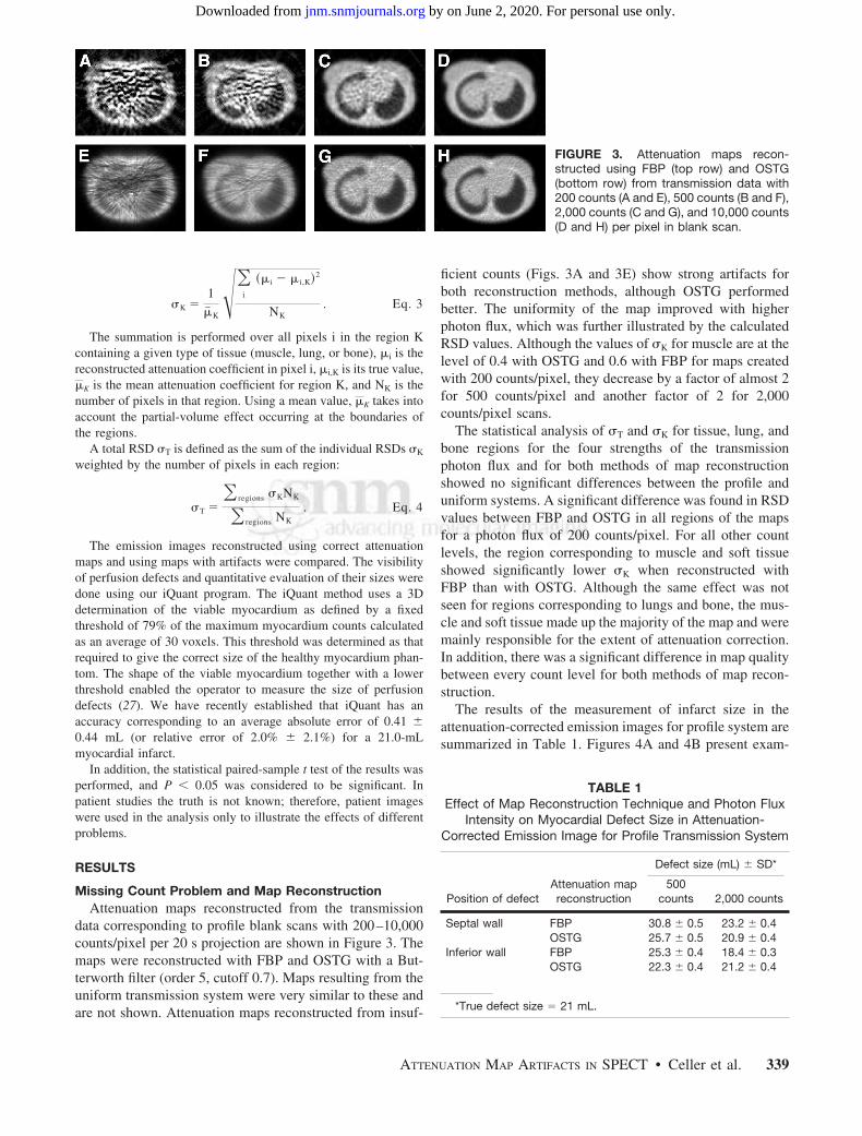
data corresponding to profile blank scans with 200–10,000counts/pixel per 20 s projection are shown in Figure 3. Themaps were reconstructed with FBP and OSTG with a But-terworth filter (order 5, cutoff 0.7). Maps resulting from theuniform transmission system were very similar to these andare not shown. Attenuation maps reconstructed from insuf-
ficient counts (Figs. 3A and 3E) show strong artifacts forboth reconstruction methods, although OSTG performedbetter. The uniformity of the map improved with higherphoton flux, which was further illustrated by the calculatedRSD values. Although the values of K for muscle are at thelevel of 0.4 with OSTG and 0.6 with FBP for maps createdwith 200 counts/pixel, they decrease by a factor of almost 2for 500 counts/pixel and another factor of 2 for 2,000counts/pixel scans.
The statistical analysis of T and K for tissue, lung, andbone regions for the four strengths of the transmissionphoton flux and for both methods of map reconstructionshowed no significant differences between the profile anduniform systems. A significant difference was found in RSDvalues between FBP and OSTG in all regions of the mapsfor a photon flux of 200 counts/pixel. For all other countlevels, the region corresponding to muscle and soft tissueshowed significantly lower K when reconstructed withFBP than with OSTG. Although the same effect was notseen for regions corresponding to lungs and bone, the mus-cle and soft tissue made up the majority of the map and weremainly responsible for the extent of attenuation correction.In addition, there was a significant difference in map qualitybetween every count level for both methods of map recon-struction.
The results of the measurement of infarct size in theattenuation-corrected emission images for profile system aresummarized in Table 1. Figures 4A and 4B present exam-
FIGURE 3. Attenuation maps recon-structed using FBP (top row) and OSTG(bottom row) from transmission data with200 counts (A and E), 500 counts (B and F),2,000 counts (C and G), and 10,000 counts(D and H) per pixel in blank scan.
TABLE 1Effect of Map Reconstruction Technique and Photon Flux
Intensity on Myocardial Defect Size in Attenuation-Corrected Emission Image for Profile Transmission System
Position of defectAttenuation mapreconstruction
Defect size (mL) SD*
500counts 2,000 counts
Septal wall FBP 30.8 0.5 23.2 0.4OSTG 25.7 0.5 20.9 0.4
Inferior wall FBP 25.3 0.4 18.4 0.3OSTG 22.3 0.4 21.2 0.4
*True defect size � 21 mL.
ATTENUATION MAP ARTIFACTS IN SPECT • Celler et al. 339
by on June 2, 2020. For personal use only. jnm.snmjournals.org Downloaded from

ples of images of the septal defect and were obtained withFBP-reconstructed maps from data created with the profilesystem. The left and the right parts of the figures showattenuation maps and corresponding heart images obtainedfrom 500 and 2,000 counts/pixel scans, respectively. Ourexperiments showed that important variations in the infarctsize for true septal and inferior myocardial wall defects maybe caused by insufficient counts in the transmission scan.The largest increase in the defect size was seen in mapsreconstructed using FBP. There was no difference betweenthe results obtained with the profile and uniform transmis-sion systems, providing the same maximum counts/pixelwere used.
Cross-Talk Problem and CorrectionsInadequate correction for cross-talk effect created prob-
lems in the attenuation maps similar to those caused by lowcounts acquisitions, especially when the simple subtractionmethod was used. Figure 5 presents examples of attenuationmaps obtained from the data created with the profile systemwith 500 and 2,000 count/pixel scans. These maps werereconstructed using FBP with no cross-talk correction (Figs.5A and 5E), using FBP (Figs. 5B and 5F) and OSTG (Figs.5C and 5G) with simple subtraction of the scatter data
acquired in the cross-talk windows, and reconstructed withthe OSTG-S iterative algorithm (Figs. 5D and 5H).
Maps with no cross-talk correction appeared to besmoother than those obtained with the cross-talk subtractionmethod. The reason is that subtracting cross-talk contribu-tion from each bin of the transmission projection substan-tially increased the statistical noise in the data. Obviously,the noise amplification effect was the strongest for the 500counts/pixel study and FBP reconstruction. When compar-ing OSTG reconstruction with FBP, improvement in mapaccuracy was more dramatic for 500 counts/pixel sourceintensity than for 2,000 counts/pixel. Further improvementwas achieved when a scatter estimate was incorporated intothe OSTG-S iterative process. In general, the RSD for eachregion decreased by about 50% for FBP and 30% for OSTGwhen the photon flux intensity increased from 500 to 2,000counts/pixel. The difference was the smallest for OSTG-Sand amounts to about 20%.
Statistical analysis was performed for the profile systemwith 500 and 2,000 counts/pixel, to compare T and K
values for different methods of map reconstruction. Forevery method of reconstruction and for each region, therewas a significant difference seen in RSD values between500 and 2,000 counts/pixel. At the photon flux of 500counts/pixel level a significant difference was seen betweenFBP and the OSTG and between FBP and OSTGS recon-structions. At the 2,000 counts/pixel level a significantdifference was seen between FBP and OSTGS but notbetween FBP and OSTG. At both levels of photon flux nosignificant difference was found between OSTG andOSTGS.
Truncation EffectsVisual and quantitative analysis of emission scans recon-
structed with maps that have been truncated show falsedefects within the myocardium and interference from activ-ity in other locations. In all of the studied cases, normal (nottruncated) attenuation maps reconstructed using OSTG andFBP provided emission scans with no detectable false de-fects and no interference from other activity. However, incases when truncated maps were used, false defects ap-peared in the myocardium.
For the profile transmission source configuration, trunca-tion occured at one side of the attenuation map when the
FIGURE 4. Attenuation maps and corresponding emissionimages of myocardial perfusion study showing increased sizesof true septal defect (A has larger defect than B) caused byinsufficient counts in maps. Maps were reconstructed usingFBP from 500 counts/pixel (A) and 2,000 counts/pixel (B) fromtransmission data obtained with profile system.
FIGURE 5. Attenuation maps recon-structed using 500 counts/pixel (top row)and 2,000 counts/pixel (bottom row) trans-mission data with no correction (A and E),cross-talk subtraction and FBP recon-struction (B and F), cross-talk subtractionand OSTG reconstruction (C and G), andOSTG-S reconstruction with cross-talk in-corporated in iterations (D and H).
340 THE JOURNAL OF NUCLEAR MEDICINE • Vol. 46 • No. 2 • February 2005
by on June 2, 2020. For personal use only. jnm.snmjournals.org Downloaded from
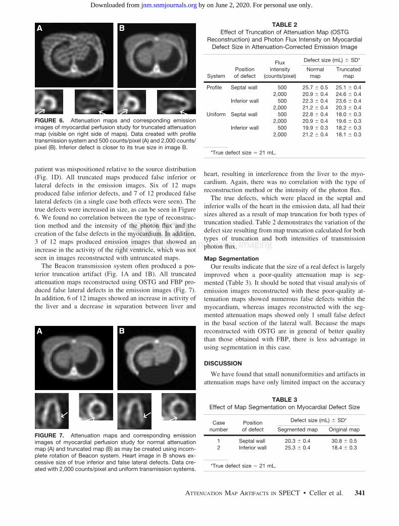
patient was mispositioned relative to the source distribution(Fig. 1D). All truncated maps produced false inferior orlateral defects in the emission images. Six of 12 mapsproduced false inferior defects, and 7 of 12 produced falselateral defects (in a single case both effects were seen). Thetrue defects were increased in size, as can be seen in Figure6. We found no correlation between the type of reconstruc-tion method and the intensity of the photon flux and thecreation of the false defects in the myocardium. In addition,3 of 12 maps produced emission images that showed anincrease in the activity of the right ventricle, which was notseen in images reconstructed with untruncated maps.
The Beacon transmission system often produced a pos-terior truncation artifact (Fig. 1A and 1B). All truncatedattenuation maps reconstructed using OSTG and FBP pro-duced false lateral defects in the emission images (Fig. 7).In addition, 6 of 12 images showed an increase in activity ofthe liver and a decrease in separation between liver and
heart, resulting in interference from the liver to the myo-cardium. Again, there was no correlation with the type ofreconstruction method or the intensity of the photon flux.
The true defects, which were placed in the septal andinferior walls of the heart in the emission data, all had theirsizes altered as a result of map truncation for both types oftruncation studied. Table 2 demonstrates the variation of thedefect size resulting from map truncation calculated for bothtypes of truncation and both intensities of transmissionphoton flux.
Map SegmentationOur results indicate that the size of a real defect is largely
improved when a poor-quality attenuation map is seg-mented (Table 3). It should be noted that visual analysis ofemission images reconstructed with these poor-quality at-tenuation maps showed numerous false defects within themyocardium, whereas images reconstructed with the seg-mented attenuation maps showed only 1 small false defectin the basal section of the lateral wall. Because the mapsreconstructed with OSTG are in general of better qualitythan those obtained with FBP, there is less advantage inusing segmentation in this case.
DISCUSSION
We have found that small nonuniformities and artifacts inattenuation maps have only limited impact on the accuracy
FIGURE 6. Attenuation maps and corresponding emissionimages of myocardial perfusion study for truncated attenuationmap (visible on right side of maps). Data created with profiletransmission system and 500 counts/pixel (A) and 2,000 counts/pixel (B). Inferior defect is closer to its true size in image B.
FIGURE 7. Attenuation maps and corresponding emissionimages of myocardial perfusion study for normal attenuationmap (A) and truncated map (B) as may be created using incom-plete rotation of Beacon system. Heart image in B shows ex-cessive size of true inferior and false lateral defects. Data cre-ated with 2,000 counts/pixel and uniform transmission systems.
TABLE 2Effect of Truncation of Attenuation Map (OSTG
Reconstruction) and Photon Flux Intensity on MyocardialDefect Size in Attenuation-Corrected Emission Image
SystemPositionof defect
Fluxintensity
(counts/pixel)
Defect size (mL) SD*
Normalmap
Truncatedmap
Profile Septal wall 500 25.7 0.5 25.1 0.42,000 20.9 0.4 24.6 0.4
Inferior wall 500 22.3 0.4 23.6 0.42,000 21.2 0.4 20.3 0.4
Uniform Septal wall 500 22.8 0.4 18.0 0.32,000 20.9 0.4 19.6 0.3
Inferior wall 500 19.9 0.3 18.2 0.32,000 21.2 0.4 18.1 0.3
*True defect size � 21 mL.
TABLE 3Effect of Map Segmentation on Myocardial Defect Size
Casenumber
Positionof defect
Defect size (mL) SD*
Segmented map Original map
1 Septal wall 20.3 0.4 30.8 0.52 Inferior wall 25.3 0.4 18.4 0.3
*True defect size � 21 mL.
ATTENUATION MAP ARTIFACTS IN SPECT • Celler et al. 341
by on June 2, 2020. For personal use only. jnm.snmjournals.org Downloaded from

of the corrected emission images. This may be explained bythe “averaging” effect on the final image, caused by theprocess of combining attenuation contributions along theprojection ray during reconstruction. Such small map arti-facts may be caused, for example, by nonuniformities of theblank scan as acquired for different angular camera posi-tions, mismatch between blank and transmission projec-tions, or by a small number of pixels with missing counts inthe transmission data. However, when missing or lowcounts extend over several pixels in the transmission pro-jections, maps reconstructed from such data may have largeareas with artificially high attenuation. This, in turn, cancreate areas with increased activity or even false hot-spotsin the reconstructed emission images. These may hide oralter the appearance of perfusion defects or give rise toapparent false defects.
The use of the iterative reconstruction OSTG method wasfound to produce maps substantially better than those cre-ated by the FBP technique. An additional advantage of thisapproach is that cross-talk correction can be included in theiterative process. Quantitative analysis of map reconstruc-tion with iterative cross-talk correction showed that theoverall accuracy of attenuation maps (total relative SD)improved by a factor of 2 when the OSTGS method incor-porating correction into iterations was used rather than FBPand subtraction. Map segmentation can improve the situa-tion when low count maps are acquired, but a segmentedmap should be used only with caution, because this proce-dure may substantially alter the position of boundaries be-tween regions with different attenuation.
Because low transmission counts can cause serious prob-lems, we recommend using transmission systems only whenthe activity of the source is sufficient. A test should be usedto verify that there are no pixels or there are, at most, onlya few pixels in the transmission projections with zero con-tent. Because this will depend on the size and density of theattenuating object, such a test should be included in thesoftware, checking the data for every single patient and,where appropriate, displaying a warning message for theuser.
To prevent low counts, the activity of the transmissionsource could be increased. Such an increase will not haveany important implication for the patient dose. The typicalpatient dose associated with a transmission scan is estimatedto be at a level of 8 � 10�5 mSv for a 30 min scan with thecurrent activity of the Profile transmission system. Thiscorresponds to approximately 1/40,000 of the patient dosefrom a sestamibi injection for a standard cardiac study.Therefore, even a 20-fold increase in the transmissionsource activity would not contribute substantially to thepatient dose. Factors that may prevent manufacturers fromusing stronger sources are probably associated with thehigher price of such a system and possible problems withhandling and shielding of higher activities.
In this respect, our comparison of the profile and uniformsystems showed the advantage of the former. In general,
maps created by both systems were almost identical, but,because of different shapes of photon beams, the totalnumber of photons used by the profile system amounted toonly 66% of the photons used by uniform, which translatedinto lower activity of the profile source being needed toproduce attenuation maps of a given quality.
CONCLUSION
In this study we have shown various type of errors,analyzed their causes, and suggested ways they could beavoided. The most important problem, resulting in inaccu-rate attenuation correction, is count deficiency in transmis-sion data. Comparison of emission images reconstructedusing low- and high-count maps showed differences thatmight lead to serious diagnostic errors. Similarly, incorrectimages could be created by inadequate cross-talk removal,because, in this case, maps contained areas with attenuationcoefficients lower than their true values and emission im-ages reconstructed with such maps had only part of theattenuation effect compensated. Truncation of transmissiondata should be avoided, because maps reconstructed fromsuch data do not represent true density distributions andusing them may substantially alter the distribution of activ-ity in the emission images.
Situations will vary, depending on the scope of the arti-fact and the sizes of the attenuation map and the activitydistribution map. Because patients are dissimilar, with dif-ferent shapes and sizes of body and internal organs, result-ing artifacts may differ from person to person. However,irrespective of all these factors, maps must be correct toproduce a correct attenuation compensation procedure. It ismost important that the attenuation maps always be viewedand checked for artifacts before attenuation-corrected im-ages are fully trusted in the diagnostic process.
ACKNOWLEDGMENT
We acknowledge the support we have received from theNatural Sciences and Engineering Research Council ofCanada.
REFERENCES
1. ElFakhri G, Buvat I, Benali H, et al. Relative impact of scatter, collimatorresponse, attenuation, and finite spatial resolution corrections in cardiac SPECT.J Nucl Med. 2000;41:1400–1408.
2. Hendel RC, Corbett JR, Cullom SJ, et al. The value and practice of attenuationcorrection for myocardial perfusion SPECT imaging: a joint position statementfrom the American Society of Nuclear Cardiology and the Society of NuclearMedicine. J Nucl Med. 2002;43:273–280.
3. Ficaro EP. Should SPET attenuation correction be more widely employed inroutine clinical practice? For. Eur J Nucl Med. 2002;29:409–412.
4. Wackers FJTh. Should SPET attenuation correction be more widely employed inroutine clinical practice? Against. Eur J Nucl Med. 2002;29:412–415.
5. Corbett J, Ficaro EP. Clinical review of attenuation-corrected clinical SPECT.J Nucl Cardiol. 1999;9:54–68.
6. Corbett J, Ficaro EP. Attenuation correction: a better cardiac SPECT. ACC CurrJ Rev. 2000;9(suppl 1):25S–31S.
342 THE JOURNAL OF NUCLEAR MEDICINE • Vol. 46 • No. 2 • February 2005
by on June 2, 2020. For personal use only. jnm.snmjournals.org Downloaded from

7. LaCroix KJ, B. Tsui MW, Frey EC, et al. Receiver operating characteristicevaluation of iterative reconstruction with attenuation compensation in 99mTc-sestamibi myocardial SPECT images. J Nucl Med. 2000;41:502–513.
8. Ficaro EP, Fessler JA, Shreve PD, et al. Simultaneous transmission/emissionmyocardial perfusion tomography: diagnostic accuracy of attenuation-corrected99mTc-sestamibi single-photon emission computed tomography. Circulation.1996;93:463–473.
9. Welch A, Gullberg GT, Christian PE, et al. A transmission-based scatter correc-tion technique for SPECT in inhomogeneous media. Med Phys. 1995;22:1627–1635.
10. Gourion D, Noll D, Celler A, et al. Attenuation correction using SPECT emissiondata only. IEEE Trans Nucl Sci. 2002;49(NS):2172–2179.
11. Wackers FJTh. Attenuation correction, or the emperor’s new clothes? J NuclMed. 1999;40:1310–1312.
12. Tung CH, Gullberg GT, Zeng GL, et al. Non-uniform attenuation correctionusing simultaneous transmission and emission converging tomography. IEEETrans Nucl Sci. 1992;39:1134–1143.
13. Chang W, Lancaric S, Huang G, et al. Asymmetric fan transmission CT onSPECT systems. Phys Med Biol. 1995;40:913–928.
14. Hawman E, Ficaro E, Hamill J, et al. Fan beam collimation with off center focusfor simultaneous emission/transmission SPECT in multi-camera SPECT systems[abstract]. J Nucl Med. 1994;35(suppl):92P.
15. Tan P, Bailey D, Meikle S, et al. A scanning line source for simultaneousemission and transmission measurements in SPECT. J Nucl Med. 1993;34:1752–1760.
16. Celler A, Sitek A, Stoub S, at al. Investigation of an array of multiple line sourcesfor SPECT transmission scans: simulation, phantom, and patient studies. J NuclMed.1998;39:2183–2189.
17. O’Connor M, Kemp B, Anstett F, et al. A multicenter evaluation of commercialattenuation compensation techniques in cardiac SPECT using phantom models.J Nucl Cardiol. 2002;9:361–376.
18. Pretorius PH, Xia W, King MA, et al. Evaluation of right and left ventricularvolume and ejection fraction using a mathematical cardiac torso phantom forgated pool SPECT. J Nucl Med. 1997;38:1528–1534.
19. Chang Z. Techniques for Reconstruction and Cross-Talk Correction for Attenu-ation Maps [thesis]. Vancouver, Canada: University of British Columbia; 2002.
20. Celler A, Axen D, Togane D, et al. Investigation of scatter in SPECT transmis-sion studies. IEEE Trans Nucl Sci. 2000;47:1251–1256.
21. Lange K, Bahn M, Little R.A. theoretical study of some maximum likelihoodalgorithms for emission and transmission tomography. IEEE Trans Med Imaging.1987;6:106–114.
22. Fessler JA. Statistical image reconstruction methods for transmission tomogra-phy. In: Sonka M. Fitzpatrick JM, eds. Medical Image Processing and Analysis;Handbook of Medical Imaging. Vol. 2. Bellingham, WA: SPIE; 2000:1–70.
23. Harrison R. SimSET home page. Available at: http://depts.washington.edu/�sim-set/html/simset_main.html. Accessed January 5, 2005.
24. Blinder S, Celler A, Wells G, et al. Experimental verification of 3D detectorresponse compensation using the OSEM reconstruction method. ConferenceProceedings IEEE NSS/MIC [on CD-ROM]. 2001.
25. Narayanan MV, King MA, Byrne CL. An iterative transmission algorithmincorporating cross-talk correction for SPECT. Med Phys. 2002;29:694–700.
26. Zaidi H, Diaz-Gomez M, Boudraa A, et al. Fuzzy clustering-based segmentedattenuation correction in whole-body PET imaging. Phys Med Biol. 2002;47:1143–1160.
27. Dixon KL, Baldwin LN, Coquinco B, et al. A robust and versatile method for thequantification of myocardial infarct size. Conference Proceedings IEEE NSS/MIC [on CD-ROM]. 2003.
ATTENUATION MAP ARTIFACTS IN SPECT • Celler et al. 343
by on June 2, 2020. For personal use only. jnm.snmjournals.org Downloaded from

2005;46:335-343.J Nucl Med. Anna Celler, Katherine L. Dixon, Zheng Chang, Stephan Blinder, John Powe and Ronald Harrop Attenuation Maps: A Simulation StudyProblems Created in Attenuation-Corrected SPECT Images by Artifacts in
http://jnm.snmjournals.org/content/46/2/335This article and updated information are available at:
http://jnm.snmjournals.org/site/subscriptions/online.xhtml
Information about subscriptions to JNM can be found at:
http://jnm.snmjournals.org/site/misc/permission.xhtmlInformation about reproducing figures, tables, or other portions of this article can be found online at:
(Print ISSN: 0161-5505, Online ISSN: 2159-662X)1850 Samuel Morse Drive, Reston, VA 20190.SNMMI | Society of Nuclear Medicine and Molecular Imaging
is published monthly.The Journal of Nuclear Medicine
© Copyright 2005 SNMMI; all rights reserved.
by on June 2, 2020. For personal use only. jnm.snmjournals.org Downloaded from