PRO Vibration Switch Family Datasheet
14
www.metrixvibraon.com • [email protected] • 281.940.1802 Doc# 1028084 • Rev R July 2017 Page 1 of 14 OVERVIEW The PRO™ vibraon switch family consists of the PRO440, the PRO450, and the PRO6000. These switches have nearly iden- cal* funconality and differ only by the enclosure mounng style and rang, allowing placement on or near the machine in the environmental condions and hazardous area classificaons typical of industrial plants. Each switch in the PRO family is programmable via a USB port and PRO configuraon soſtware, or via the switch’s integral keypad/display. Advanced capabilies allow PRO switches to de- liver self-contained, single-channel vibraon protecon with one or (oponal) two fully adjustable alarm levels and corresponding electro-mechanical relays. Alarm and startup delays are inde- pendently programmable, local reset capabilies are provided, and terminals are available for remotely invoking switch bypass and switch reset. Independent 4-20 mA and buffered transduc- er output wiring terminals are provided for connecon to plant control systems and condion monitoring instruments. Status LEDs and a 2-line alphanumeric display are standard, allowing the user to locally assess vibraon levels, alarm condions, and sensor OK condions. * The PRO450 is available with an oponal internal BNC connec- tor for the buffered signal output. This opon is not available on the PRO440 or PRO6000. This housing is not available with a viewing window and the cov- er must be removed to use the display. It is intended primarily for applicaons where an 450 is being upgraded. Replacement of the housing rather than just the internals ensures that the housing’s nameplate will carry the PRO switch’s serial number, part number, and other details, rather than those of the 450 it is replacing. When both a viewing window and Div 1 or Zone 1 hazardous area approvals are required, the PRO6000 should be used instead. It is smaller than the PRO450 in every dimension and uses a stud mount. An oponal adapter is available for flat- base mounng (p/n 7084-001); however, it uses a different hole paern than the 450 and will require new holes to be drilled in the mounng surface. Two basic switch/sensor configuraons are supported by all 3 housing styles: 1. Internal Sensor When ordered with an internal accelerometer, the switch can be mounted directly at the measurement locaon and can monitor vibraon in either acceleraon units or integrated acceleraon (velocity) units. This configuraon is suitable when there is suf- ficient room at the measurement locaon to mount the switch, when the measurement locaon sll allows the switch to be conveniently viewed and serviced by plant personnel, and when the switch’s ineral mass will not compromise the quality of the vibraon measurement. PRO Vibraon Switch Family Datasheet • PRO440 This housing uses the same 3-hole flat- base footprint as the older 440 switch. It is 22mm taller and 41mm wider than its predecessor and has two conduit fings instead of one. The cast aluminum housing carries a NEMA 4/4X/IP65 rang and comes standard with a viewing window and powder-coat epoxy. • PRO6000 This Explosion-Proof (XP) cast alumi- num housing is nearly idencal in all dimensional aspects to those of its predecessor, the SW6000/SM6100. The housing carries a NEMA 4/4X/ IP65 rang and comes standard with a viewing window and powder-coat epoxy. It uses a stud mount. An op- onal adapter is available for flat-base mounng (p/n 7084-001). • PRO450 This Explosion-Proof (XP) cast alumi- num housing is the same as used with the older 450. It carries a NEMA 4 rang and comes standard with a gray painted finish. 2. External Sensor The PRO supports connecon of an external vibraon sensor (constant-current accelerometers, piezo-velocity sensors, and moving-coil velocity sensors). When possible, an external sensor is generally preferred for most applicaons. This configuraon allows the sensor to be mounted at the ideal measurement locaon and orientaon on the machine, without concern for the larger mounng footprint of the PRO compared to a sen- sor. It also allows the PRO to be mounted in a more convenient locaon for viewing and servicing. Also, although the PRO is packaged to survive harsh environments of dust, moisture, and corrosion, some machines may exhibit elevated temperatures at the preferred sensor locaon. Use of an external sensor can allow a sensor with an elevated temperature rang, beyond that of the PRO switch electronics. The PRO switch also accepts generic transmier signals such as from vibraon*, impact, temperature, level, flow, and others that provide an ISA-standard proporonal 4-20 mA output. However, the PRO is not directly compable with temperature sensors such as RTDs and thermocouples; an intervening 4-20 mA transmier must be used instead. (ENCLOSURE ONLY)
Transcript of PRO Vibration Switch Family Datasheet

www.metrixvibration.com • [email protected] • 281.940.1802Doc# 1028084 • Rev R July 2017 Page 1 of 14
OVERVIEW
The PRO™ vibration switch family consists of the PRO440, the PRO450, and the PRO6000. These switches have nearly identi-cal* functionality and differ only by the enclosure mounting style and rating, allowing placement on or near the machine in the environmental conditions and hazardous area classifications typical of industrial plants.
Each switch in the PRO family is programmable via a USB port and PRO configuration software, or via the switch’s integral keypad/display. Advanced capabilities allow PRO switches to de-liver self-contained, single-channel vibration protection with one or (optional) two fully adjustable alarm levels and corresponding electro-mechanical relays. Alarm and startup delays are inde-pendently programmable, local reset capabilities are provided, and terminals are available for remotely invoking switch bypass and switch reset. Independent 4-20 mA and buffered transduc-er output wiring terminals are provided for connection to plant control systems and condition monitoring instruments. Status LEDs and a 2-line alphanumeric display are standard, allowing the user to locally assess vibration levels, alarm conditions, and sensor OK conditions.
* The PRO450 is available with an optional internal BNC connec-tor for the buffered signal output. This option is not available on the PRO440 or PRO6000.
This housing is not available with a viewing window and the cov-er must be removed to use the display. It is intended primarily for applications where an 450 is being upgraded. Replacement of the housing rather than just the internals ensures that the housing’s nameplate will carry the PRO switch’s serial number, part number, and other details, rather than those of the 450 it is replacing. When both a viewing window and Div 1 or Zone 1 hazardous area approvals are required, the PRO6000 should be used instead. It is smaller than the PRO450 in every dimension and uses a stud mount. An optional adapter is available for flat-base mounting (p/n 7084-001); however, it uses a different hole pattern than the 450 and will require new holes to be drilled in the mounting surface.
Two basic switch/sensor configurations are supported by all 3 housing styles:
1. Internal SensorWhen ordered with an internal accelerometer, the switch can be mounted directly at the measurement location and can monitor vibration in either acceleration units or integrated acceleration (velocity) units. This configuration is suitable when there is suf-ficient room at the measurement location to mount the switch, when the measurement location still allows the switch to be conveniently viewed and serviced by plant personnel, and when the switch’s inertial mass will not compromise the quality of the vibration measurement.
PRO Vibration Switch FamilyDatasheet
• PRO440This housing uses the same 3-hole flat-base footprint as the older 440 switch. It is 22mm taller and 41mm wider than its predecessor and has two conduit fittings instead of one. The cast aluminum housing carries a NEMA 4/4X/IP65 rating and comes standard with a viewing window and powder-coat epoxy.
• PRO6000This Explosion-Proof (XP) cast alumi-num housing is nearly identical in all dimensional aspects to those of its predecessor, the SW6000/SM6100. The housing carries a NEMA 4/4X/IP65 rating and comes standard with a viewing window and powder-coat epoxy. It uses a stud mount. An op-tional adapter is available for flat-base mounting (p/n 7084-001).
• PRO450This Explosion-Proof (XP) cast alumi-num housing is the same as used with the older 450. It carries a NEMA 4 rating and comes standard with a gray painted finish.
2. External SensorThe PRO supports connection of an external vibration sensor (constant-current accelerometers, piezo-velocity sensors, and moving-coil velocity sensors). When possible, an external sensor is generally preferred for most applications. This configuration allows the sensor to be mounted at the ideal measurement location and orientation on the machine, without concern for the larger mounting footprint of the PRO compared to a sen-sor. It also allows the PRO to be mounted in a more convenient location for viewing and servicing. Also, although the PRO is packaged to survive harsh environments of dust, moisture, and corrosion, some machines may exhibit elevated temperatures at the preferred sensor location. Use of an external sensor can allow a sensor with an elevated temperature rating, beyond that of the PRO switch electronics.
The PRO switch also accepts generic transmitter signals such as from vibration*, impact, temperature, level, flow, and others that provide an ISA-standard proportional 4-20 mA output. However, the PRO is not directly compatible with temperature sensors such as RTDs and thermocouples; an intervening 4-20 mA transmitter must be used instead.
(ENCLOSURE ONLY)

www.metrixvibration.com • [email protected] • 281.940.1802Doc# 1028084 • Rev R July 2017 Page 2 of 14
*The PRO switch provides only over-type (not over/under) alarms. As such, it can be used with radial vibration transmitters (such as the Metrix TXR); however, it cannot be used with axial position transmitters (such as the Metrix TXA) for thrust bearing protection applications which require over/under type alarms.
FEATURES AND BENEFITS
• Programmable configuration allows the user to configure virtu-ally every switch option in the field, via the display’s keypad, or via USB connection to the PRO configuration software. Multiple switch configurations in a plant can be supported by a single PRO, reducing spare part requirements and complexity.
• One or (optional) two alarm levels are available, allowing sep-arate shutdown (Danger) and pre-shutdown (Alert) setpoints.
• Bright, dot-matrix LED 2-line display is standard with every PRO switch, allowing the user to see not only current readings, but the associated engineering units. Eliminates scrolling and ambiguity as to what units are being displayed, or whether RMS or Peak detection is being used. Display is visible under all lighting conditions, including complete darkness.
• Configurable for True Peak or RMS on all vibration measure-ments. Unlike devices that use an RMS detector and merely scale the reading to obtain “pseudo peak” (RMS x 1.414), the PRO switch features both a true peak detection circuit and a true RMS detection circuit, allowing you to choose either one with confidence that the readings delivered will be accurate.
• 4-20 mA outputs allow the switch to provide the measured vi-bration level as a proportional 4-20 mA signal, ideal for PLCs, DCSs, and other plant control and automation systems that can provide trending and remote display of vibration levels for operators.
• Programmable power-up delay bypasses alarming functions after switch is energized. The delay is fully programmable from 20-30 seconds in 1-second increments.
• Programmable alarm delay can be set from 1 to 15 seconds in 1-second increments. Helps eliminate spurious alarms by en-suring that only vibration conditions persisting for more than the pre-set delay will trigger an ALERT or SHUTDOWN.
• Remote reset capabilities allow the user to connect a remote contact closure for resetting the switch when latching-type alarms are used.
• Flexible bypass / startup delay options allow an external contact closure to bypass the switch’s alarming functions indefinitely. When in bypass, the switch continues to display measured vibration levels and output a proportional 4-20 ma signal; however, alarms cannot activate. This feature is useful when maintaining the instrument to prevent unwanted machine trips or alarms. It can also be used as a startup delay for any desired duration – simply leave the bypass terminals
shorted as invoked by a PLC or other machine controller with timer- or state-based logic. This ensures the switch will not trip a machine during its starting sequence when higher-than-normal vibration levels may be encountered. In contrast, other switch types may not provide the necessary level of flexibility to establish an appropriate machine startup delay.
• Multi-color LEDs clearly and unambiguously annunciate OK, Bypass, and Alarm conditions. Loss of power can also be ascertained via OK LED (green = OK, red = NOT OK, off = no power).
• Individual SPDT electro-mechanical relays are provided for each alarm, allowing more flexibility in choice of loads than solid-state relays. Relays are configurable1 for normally ener-gized or normally de-energized operation, as well as latching and non-latching. Both N.O. and N.C. wiring terminals are provided.
• Buffered signal output terminals allow wiring from the switch back to a patch panel or other termination for convenient connection to portable data collectors, analyzers, and other instruments.
• Local reset capabilities allow the user to easily reset the switch by accessing the keypad on the display.
• Hazardous area approvals are currently available3 for CSA Division 1 and Division 2.
• 4-20 mA input capabilities allow the switch to monitor and alarm on any generic 4-20 mA signal, such as from pressure, temperature, flow, impact, or any other transmitter type (in-cluding proximity probes2). The configuration software allows custom scales and engineering units.
• Wide variety of external input types allow the user to select from virtually any type of seismic transducer including constant-current accelerometers, piezo-velocity transducers, and moving-coil velocity transducers. Scale factors are highly configurable, allowing compatibility even with non-standard sensor types.
• Available with an internal accelerometer for completely self-contained operation when an external sensor isn’t practical.
• Simple, intuitive configuration fits on a single screen using the Windows-based PRO configuration software for at-a-glance visibility of all switch settings.

www.metrixvibration.com • [email protected] • 281.940.1802Doc# 1028084 • Rev R July 2017 Page 3 of 14
• User-defined notes can be added to the switch’s non-volatile memory via the PRO configuration software. Plant-specific instrument loop numbers, asset tag numbers, date of last ser-vice and service person, and any other data can be entered in up to 4 separate free-text fields.
• Wide variety of mounting styles allow 3-hole flat-base mount-ing (PRO440), 4-hole flat-base mounting (PRO450), and stud mounting (PRO6000). For convenience when upgrading4 an existing installation, PRO mounting footprints are identical to their predecessors, and the housing dimensions closely match as well.5
NOTES:1. Dual relays are configured in pairs. It is not possible to config-ure one relay as latching and the other non-latching, or one as energized and the other non-energized.2. Axial position transmitters are not supported. They require over/under alarming which is not available in the PRO switch family.3. The PRO440 is approved for use in Class I / Class II Div 2 areas. The PRO6000 is approved for use in Class I / Class II Div 1 areas. Class I / Class II Div 1 approvals are for the PRO450 enclosure only. 4. Not all features in the SW- and SM-series switches are replicated in the PRO. Consult your Metrix sales professional to review your application before selecting a PRO switch as a replacement or spare for an 440, 450, SW6000, or SM6100. See also “Retrofit Considerations”.5. Refer to pages 12-13 for dimensional comparisons of PRO440 and PRO6000 switches versus their predecessors.
RETROFIT CONSIDERATIONSThe PRO series has been designed to use in most applications where the 440, 450, SW6000, and SM6100 would have been used previously. However, although the PRO series adds many new features and functions, it does not replicate every capabil-ity of predecessor switches. There are instances in which select functionality is not available in the PRO series and a different Metrix switch will represent a better fit for the application. If you are considering the purchase of a PRO switch as a spare or replacement for an existing 440, 450, SW6000, or SM6100, please consult the factory or your nearest Metrix sales profes-sional to ensure compatibility.
The following features are not currently available in the PRO series:• External BNC connector
This option was available on selected 440, SW6000, and SM6100 switches. External BNC connectors are not permit-ted on switches carrying hazardous area approvals. A BNC connector option is available with the PRO450 only; howev-er, it is internal rather than external. All PRO switches come standard with wiring terminals for the buffered transducer output, allowing connection to a suitable remote patch panel or other termination.
• External Reset Pushbutton This feature was available on selected 440, SW6000, and SM6100 switches. The cover must be removed from the PRO housing to access the display keypad, allowing latched alarms to be reset. Alternatively, wiring connections are provided on the PRO switch for an external reset signal and these may be wired to a local or remote reset pushbutton.
• Seismic Displacement The SW6000 and SW6100 allow single- or double-integra-tion into displacement. The PRO switch does not support seismic displacement units unless an external velocity transducer is used with an intervening signal conditioner, such as the Metrix 5534/5544 which provides single integra-tion. Acceleration-to-displacement measurements are not available.
• Solid-State Relays This feature was available on the 440, 450, SW6000, and SM6100. The PRO series is available only with electro-me-chanical relays. If you are using the PRO in an installation that previously used solid-state relays (i.e., triacs or FETs), please ensure that the relays in the PRO switch are compat-ible with the loads they will be switching.
• Selected Hazardous Area Approvals The PRO switch does not currently carry all of the same haz-ardous area approvals as its predecessors. Before replacing an 440, 450, SW6000, or SM6100, please ensure that the PRO has obtained the required agency approvals.

www.metrixvibration.com • [email protected] • 281.940.1802Doc# 1028084 • Rev R July 2017 Page 4 of 14
SPECIFICATIONSAll specifications are at +23°C (+73°F) and 100 Hz unless otherwise noted.
• Metrix 5534/5544• Others providing a 4-20 mA signal proportional to vibration amplitude (not gap)*
* The PRO switch cannot be used for axial position (thrust) monitoring as it is not capable of over/under type alarming required by such measurements. Do not attempt to use a Metrix TXA, 5488, or other axial position transmitter with the PRO for thrust bearing protection.
RPM Transmitters• Metrix PT5521 • Other RPM transmitters providing a 4-20 mA output proportional to rotative speed
CautionThe PRO switch is intended for display and annuncia-tion of speed only. Use as part of a speed control or overspeed protection system constitutes a misapplica-tion of the product. Other 4-20 mA TransmittersThe PRO switch accepts any ISA-standard 4-20 mA signal and allows configuration of custom engineering units. This allows it to monitor virtually any param-eter* including temperature, flow, pressure, level, or other process variables that can be supplied in a 4-20 mA format. The PRO provides 24 Vdc @ 25 mA to power a connected transmitter.
* Measurements requiring over/under alarming are not supported.
Maximum Signal Amplitude
• 5 Vac pk-pk for all mV sensor inputs• 20 mA dc for all transmitter inputs
Full-Scale Range
• Internal accelerometer:50-100 m/s2 (5-10 g)20-76 mm/sec (0.8-3.0 ips) • External accelerometers: 50-500 m/s2 (5-50 g)* 20-127 mm/sec (0.8-5.0 ips) • External velocity sensors (piezo and moving-coil):20-127 mm/sec (0.8-5.0 ips)• 4-20 mA transmitters: -999.9 to +999.9
* External accelerometers with sensitivities above 70 mV/g (7.1 mV/m/s2) will decrease the available full-scale range.
Input PowerVoltage*
• AC: 85 – 230 Vac, 50-60 Hz• DC: 24 ± 2.4 Vdc
* AC or DC power must be specified at time of order-ing and is not field-configurable.
Power Consumption
≤ 6 W
Power Terminal Ratings
• Nominal Current: 17.5 A• Max. Load Current: 22A• Nominal Voltage: 250 Vac• Rated Voltage: 320 Vac• Insulation: Polyamide (PA)• UL94 Flammability Class: V0
Input
Channels 1
Channel Types
• Acceleration• Velocity• Integrated Acceleration• Impact Count• 4-20 mA / Custom*
* 4-20 mA channels are the only type that can be configured for custom units using up to 5 characters (a-z, A-Z, and /). The minimum scale (4mA) and maximum scale (20 mA) values may be configured between -999.9 and +999.9, regardless of units; however, the maximum scale must always be greater than the minimum scale.
Transducer Types
Acceleration Sensors• Metrix SA6200A• Metrix SA6350• PRO internal 100 mV/g accelerometer• Constant-current accelerometers with sensitivities from 1.0-11.2 mV/m/s2 (10 - 110 mV/g)*
* The internal accelerometer option restricts scale factor to 100 mV/g. All other external accelerometer sensitivities can be configured in 0.1 mV increments.
Piezo-Velocity Sensors• Metrix SV6300• Constant-current piezo-velocity sensors with sensitivi-ties from 3.9-19.7 mV/mm/s (100-500 mV/in/sec)* * External piezo-velocity transducer sensitivities can be config-ured in 0.1 mV increments.
Moving-Coil Velocity Sensors• Metrix 5485C*• Moving-coil velocity sensors with sensitivities from 3.9-19.7 mV/mm/s (100-500 mV/in/sec)*
* Moving-coil velocity transducer sensitivities can be config-ured in 0. 1 mV increments. The 5485C restricts scale factor to four discrete selections: 105, 145, 150, and 200 mV/ips.
Impact Transmitters*•Metrix IT6810/6811/6812
* Metrix impact transmitters provide a 4-20 mA signal propor-tional to the number of impacts per unit time above an adjust-able threshold level. The sensor’s output signal is a discrete mA level in 1 mA increments where 4 mA = 0 impacts, 20 mA = 16 impacts, and 12 mA = 8 impacts.
Vibration Transmitters and Signal Conditioners w/ 4-20 mA output• Metrix TXR• Metrix ST5484 / ST5491 • Metrix 162VTS• Metrix ST6911• Metrix ST6917• Metrix 5565• Metrix 5510• Metrix 5535/5545

www.metrixvibration.com • [email protected] • 281.940.1802Doc# 1028084 • Rev R July 2017 Page 5 of 14
Input Impedance
• Moving-coil velocity: 10 kΩ or 100 kΩ (software-configurable) • Constant-current sensors: adjusts automatically to maintain 4 mA bias current• 4-20 mA transmitters: 100 Ω
Bypass Invoked by shorting BYP wiring terminals. Switch displays measurement level and provides proportional 4-20 mA output, but defeats all alarming functions. Bypass conditions persists for as long as terminals are shorted. Monitoring resumes immediately upon removing short.
Reset • Resets latched alarms• Invoked locally at keypad/display using ALARM RESET menu• Invoked remotely by momentary short of RST wiring terminals.
OutputsRelays • Number: 1 or (optional) 2
• Type: SPDT, form C• Minimum Switching Capacity: 100 mA @ 5Vdc• Maximum Switching Capacity: 2500 VA10A @ 250 Vac or 5A @ 100 Vdc • N.O. and N.C. wiring terminals available for each relay• Software-configurable options:
o Energize or De-Energize*o Latching or Non-Latching*
* Dual relays are configured in pairs. It is not possible to configure one relay as latching and the other non-latching, or one as energized and the other non-energized.
4-20 mA • Number: 1 • Output proportional to channel programmable full scale range*• Max Load Resistance (RL): 600 Ω • Accuracy: ± 1% of full scale 4 mA ± 0.25 mA @ min. scale• Supply: Sourcing 24 Vdc, isolated from switch• Short-circuit protected: Yes• NOT OK Clamp: < 3.8 mA• Max. Output: 20 mA (100% of full scale)
* When the input is a 4-20 mA signal, the PRO’s 4-20 mA output will act as a repeater.
LEDs • OK LED Green – Sensor Connection OKRed – Sensor Connection NOT OKOff – Switch has lost power• Bypass LEDRed – Switch in bypass modeOff – Switch not in bypass mode• Alarm LED Yellow – ALARMRed – SHUTDOWN (available on dual-relay versions only)Off – No alarm
Display • 2 lines • 8 characters per line• 4x7 green LED dot-matrix per character• Display Resolution: 5 digits• Display indicates current readings and associated engineering units. Can be used to view and change configuration settings by accessing appropriate menus, and for local reset.
Keypad 4 membrane-style keys• g• i• MENU• ENTER
Transducer Power
• 4-20 mA transmitters: 24Vdc @ 25 mA• Constant-current accelerometers and piezo-velocity devices: 24 Vdc @ 4 mA• Moving-coil velocity transducers: 12 Vdc bias voltage* * Although moving-coil velocity transducers are self-pow-ered, a bias voltage is provided for sensor OK checking.
Buffered Transducer Outputs
Locations• Wiring terminals inside PRO enclosure • BNC connector inside PRO450 enclosure** Available on PRO450 only. Must be specified when ordering.Impedance• 1 kΩShort-Circuit Protected• Yes (output may be shorted indefinitely without affecting switch operation)Accuracy• ± 5% of measurement3 dB Bandwidth• DC to 20 kHz*Cable Drive• Up to 305 m (1000 ft) of cable may be connected without degradation of signal** Cable lengths beyond this will introduce excessive ca-pacitance, degrading the frequency response. Consult the factory for specific roll-off data for longer lengths.Signal Type• Raw (unfiltered, no integration) transducer signal in mV/engineering units*
* When the optional 100 mV/g internal accelerometer is used and the switch is configured to monitor integrated acceleration, the buffered output will not be integrated and will reflect the raw 100 mV/g signal. When integrating the signal from an external accelerometer, the buffered output will likewise reflect the raw acceleration signal, not the integrated signal.
Configuration
Method All PRO switches support both of the following con-figuration methods:
• PC-based PRO™ configuration software • Integral display/keypad
While in configuration mode, the switch is disabled. It provides no display, no alarming, and no 4-20 mA output.
Connection Type
USB 1.1 (USB Type B receptacle on PRO – must detach display to access)
Memory Location
Configuration data is stored in switch’s non-volatile RAM until changed. Batteries or other power sources are not required to retain configuration data.
Supported Operating Systems
• Windows XP (SP2 or later)• Windows 7 (32- and 64-bit)
NOTE: The software has not been tested on Windows Vista and support is not available for this operating system.

www.metrixvibration.com • [email protected] • 281.940.1802Doc# 1028084 • Rev R July 2017 Page 6 of 14
Configurable Options • Alarm delay (1-20 sec in 1-sec increments; affects both alarm and shutdown)• Power-up delay (20-30 sec in 1-sec incre-ments)• Latching/Non-Latching Relays• Energized/De-Energized Relays• Input Type
o Internal Accelerometero External Accelerometero External piezo-velocityo External electromechanical velocityo Metrix 5485C velocityo 4-20 mA transmitter
• Transducer Sensitivity• Input Impedance*• Measurement Unit
o Acceleration: g or m/s/so Velocity: sec or mm/seco Impacts: IMPS (impacts)
• Custom Unit (4-20 mA channel types only): up to 5 characters (a-z, A-Z, /)• Full-Scale Range• Mode (vibration channel types only): RMS or PEAK • Shutdown Level (0-90% of full scale)• Alarm Level**(must be less than shutdown level)• Up to 4 user-defined notes
* Available for electromechanical velocity inputs only** Available with dual relay models only
Signal Conditioning
A/D Resolution 12 bits
Integration Configurable for:• None• Single (Acceleration-to-Velocity only)
NOTE: Velocity-to-displacement integration (seis-mic displacement) can be accomplished by means of an external velocity transducer and an external signal conditioner such as the Metrix 5534/5544. The displacement signal is provided in 4-20 mA proportional format and the PRO is configured for custom units of mils or um.
Peak Detection Vibration channel types are configurable for either:• True Peak• True RMS
Accuracy Vibration Channels• Acceleration: ± 3%• Integrated Acceleration: ± 6%• Velocity: ± 3%
4-20 mA Channels: ± 1%
Frequency Response*(± 3 dB)
2 Hz – 5 kHz
* Frequency response may be further limited by the transducer itself when using an external transducer input.
Self-Test Capabilities
Relay Test Forces opened / closed condition of relays, indi-vidually
Current Output Test
Allows user to drive current output to any of the following values: 4, 8, 12, 16, or 20 mA
Digital Input Test Forces BYPASS and RESET functions, individually
Power Supply Monitor
Checks status of internal 24 Vdc power supply
Display Test Lights all LED elements in dot-matrix display to confirm that all are working
Key Test Prompts user to press each of the 4 available keypad buttons, confirming proper operation
LED Test Forces LEDs into each available state/color, indi-vidually
Internal Signal Test
Generates a 1kHz test signal to exercise various internal circuit paths, confirming operation
Access All self-test functions may be invoked via the local keypad/display or via the PRO configuration software
Environmental
Operating Temp. -40C to +70C (-40 to + 158°F)
Vibration ≤ 10g NOTE: If more than 10g will be encountered at the mea-surement location, use an external sensor and mount the PRO switch remotely.
Humidity 100% condensing
Enclosure Ratings
• PRO440: NEMA 4X / IP65• PRO6000: NEMA 4X / IP65, explosion-proof• PRO450: NEMA 4, explosion-proof
Approvals
EMC • European EMC Directive (2014/30/EU)• FCC 47 CFR, Part 15 Subpart B, Class A• ANSI C63.4
CSA • PRO440: Class I, Div 2, Groups B-D, T4, NEMA 4/4X, IP65Class II, Div 2, Groups F,G, T4, NEMA 4/4X, IP65• PRO6000: Class I, Div 1, Groups B-D, T4A, NEMA 4/4X, IP65Class II, Div 1, Groups E-G, T4A, NEMA 4/4X, IP65
CSA/UL • PRO450 (Enclosure):Class I, Div 1, Groups B-DClass II, Div 1, Groups E-G
Physical
Size Refer to Figures 2-4.
Weight 1.8 kg (4 lbs)
Enclosure Material
Copper-free cast aluminum
• PRO440: Powder-coat epoxy (Pantone 302 blue)• PRO6000: Powder-coat epoxy (Pantone 302 blue)• PRO450: Paint (gray)** Epoxy clear-coat available as an option on PRO450. Housing carries NEMA4 rating whether with or without epoxy option.

www.metrixvibration.com • [email protected] • 281.940.1802Doc# 1028084 • Rev R July 2017 Page 7 of 14
PRO Vibration SwitchAA Pro Model
01 440 Single Relay (SR)
02 440 Dual Relay (DR)
03 6000 Single Relay (SR)
04 6000 Dual Relay (DR)
05 450 Single Relay (SR)
06 450 Dual Relay (DR)
07 450SR w/ BNC
08 450DR w/ BNC
BB Display
02 Display included
CC Power
01 85-230 Vac, 50/60 Hz
02 24 Vdc
DD Agency Approvals
01 No Approvals
02 CSA Div 11
03 CSA Div 22
EE Conduit/Stud Threads3
01 ¾“ NPT / ½” NPT
02 M20 x 1.5 / M20 x 1.5
FF Sensor Type
01 Internal Accelerometer (100 mV/g)
02 External Accelerometer
03 Piezo-Velocity
04 5485C
06 Moving-coil velocity
07 Impact Transmitter
08 ST5484E
09 4-20mA
GG Input Sensitivity4
00 Internal Accelerometer
01 10 mV/g
02 100 mV/g
03 100 mV/in/sec
04 105 mV/in/sec
05 145 mV/in/sec
06 150 mV/in/sec
07 200 mV/in/sec
ORDERING INFORMATION
AA BB CC DD EE FF GG HH JJ KK LL MM NN
PRO___ 02
Software Programmable OptionsOptions GG-NN may be specified at time of ordering or left blank. If not specified, factory default options (indicated by bold type) will be
supplied. These default configurations can be changed in the field via the keypad/display or via the Windows-based configuration software.
HH Full Scale Range5
01 0.8 in/sec
02 1.0 in/sec
03 1.5 in/sec
04 2.0 in/sec
05 3.0 in/sec
06 5.0 in/sec6
07 12.7 mm/sec
08 20 mm/sec
09 25 mm/sec
10 40 mm/sec
11 50 mm/sec
12 80 mm/sec6
13 125 mm/sec6
14 10 g
15 35 g6
16 50 g6
17 100 m/s/s
18 500 m/s/s
19 16 impacts
JJ Detection Mode
01 True Peak
02 RMS
KK Trip Delay
01 1 seconds (min)
02 2 seconds
03 3 seconds
XX Delay in seconds (from 1-20)
20 20 seconds (max)
LL Startup Delay
20 20 seconds (min)
XX delay in seconds (from 20-30)
30 30 seconds (max)
MM Relay Latching
01 Latching
02 Non-Latching
NN Relay Mode
01 Non-Energized
02 Energized

www.metrixvibration.com • [email protected] • 281.940.1802Doc# 1028084 • Rev R July 2017 Page 8 of 14
NOTES:1. Available with PRO6000 only: CSA Class I Div 1 Groups B-D, temp
code T4A, enclosure type 4/4X, IP65 and Class II Div 1 Groups E-G. Available with PRO450: enclosure is CSA/UL Class I, Div I, Groups B-D and Class II, Div 1, Groups E-G.
2. Available with PRO440 only. CSA Class I Div 2 Groups B-D, T4, NEMA 4/4X, IP65 and Class II Div 2 Groups F and G.
3. Mixed metric and English threads (metric conduit sizes with Eng-lish mounting studs or vice-versa) can be supplied upon request as a factory special. Please specify at time of ordering.
4. The input sensitivity can be configured to any value between the limits below: External Accelerometer: 1.0-11.2 mV/(m/s/s) or 10-110 mV/g External Velocity: 3.9-19.7 mV/(mm/sec) or 100-500 mV/(in/sec)
5. The full scale range can be configured to any value between the limits below: Acceleration: 50-500 mV/(m/s/s) or 5-50 g Velocity: 20-127 mm/sec or 0.8-5 in/sec 4-20 mA: Same as full scale range of input transducer
6. These full scale options exceed the internal accelerometer’s range and are not available when an internal accelerometer is specified.
Caution: When ordered without specifying options GG – NN, the PRO switch is shipped with factory default configuration settings which are not necessarily suit-
able for any particular application. Before use, ensure that the switch is configured properly for its application via the keypad/display or via PRO configuration software. This software is avail-able for download at www.metrixvibration.com.
ACCESSORIES
PRO6000 - Flush Mounting Adapter This stainless-steel adapter allows a PRO6000 to be flush mounted on a flat surface. The adapter provides a ½” NPT threaded hole* in the center and three equally spaced 0.26” (6.6 mm) smooth holes on a 1.50” (38 mm) circle. 7084-001 - Flange Mounting Adapter* NOTE: The flange mounting adapter is not compatible with PRO6000 switches that have a metric mounting stud.
USB cableA 3m (10-foot) USB cable is included with each order for PRO switches. Use the part number below only for spares or replacements.100468 - 3m USB cable (Type A male to Type B male)
SOFTWARE
PRO configuration software is available free-of-charge at www.metrixvi-bration.com.
Features 440 PRO440 450 PRO450 SW6000 SM6100 PRO6000
Primary Attributes
Single Relay Version (SR) STD STD STD STD STD STD STD
Dual Relay Version (DR) $OPT $OPT $OPT $OPT $OPT $OPT $OPT
Display STD STD $OPT $OPT STD
Programmable Configuration STD STD STD
4-20 mA output (self-powered) STD STD STD STD $OPT $OPT STD
4-20mA Loop Test Feature STD STD STD
Signal Conditioning
Velocity-to-Displacement Conversion OPT
Acceleration-to-Displacement Conversion OPT OPT
Acceleration-to-Velocity Conversion STD STD STD STD OPT OPT STD
Display in acceleration units (no integration) STD STD STD
Display Impact counts (for Impact Transmitter input) STD STD STD
True Peak amplitude detection STD STD STD
“Derived Peak” (RMS x 1.414) amplitude detection STD STD1 STD STD1 OPT OPT STD1
True RMS amplitude detection STD STD OPT OPT STD
SWITCH FEATURE COMPARISON
STD: Standard Feature, included in base priceOPT: Standard Option, included in base price$OPT: Standard Option, additional pricePEND: Pending, planned but not yet available

www.metrixvibration.com • [email protected] • 281.940.1802Doc# 1028084 • Rev R July 2017 Page 9 of 14
Features 440 PRO440 450 PRO450 SW6000 SM6100 PRO6000
Transducer Input Type
Internal Accelerometer $OPT $OPT $OPT $OPT STD $OPT
Accepts External Acceleration Sensors STD2 3 STD STD2 3 STD STD STD
Accepts External Piezo-Velocity Sensors STD STD OPT STD
Accepts External Moving-Coil Velocity Sensors STD STD OPT STD
Accepts External Displacement Sensors STD
Accepts 5485C Hi-Temp Velocity Transducer STD STD OPT STD
Accepts IT 681X Impact Transmitters STD STD STD
Accepts any 4-20mA input signal STD STD STD
Accepts 4-20 mA vibration transmitters STD STD STD
Approvals
No Approvals STD STD STD STD STD
CE Mark STD STD
CSA, Div 2 STD22 $OPT2 6
CSA, Div 1 STD2 3 PEND $OPT2 4 $OPT2 4 $OPT2 4
GOST (Russia) $OPT $OPT
GOST K (Kazakhstan) $OPT $OPT
IECEx $OPT2 5 $OPT2 5
ATEX Zone 2
ATEX Zone 1 $OPT2 5 $OPT2 5
Wiring Connections
Buffered output terminals STD STD STD STD STD
Buffered output BNC connector $OPT4 $OPT5 $OPT4 $OPT4
USB connector for configuration and verification STD STD STD
External Local Reset Button (weatherproof) $OPT $OPT $OPT
External Local Reset Button (XP / flameproof) $OPT $OPT
Terminals for activating BYPASS condition STD STD STD
Terminals for wiring remote reset STD STD STD STD STD STD STD
Terminals for activating Lockout / Startup delay6 $OPT $OPT STD STD
Mounting and Conduit
¾ NPT conduit fittings7 ONE TWO ONE ONE TWO8 TWO8 TWO
M20 x 1.5 conduit fittings7 ONE TWO ONE ONE TWO8 TWO8 TWO
Stud Mount – ½-14 NPT7 STD STD STD
Stud Mount – M20 x 1.57 OPT OPT OPT
Stud Mount – ½-20 UNF (straight threads) with jam nut $OPT $OPT
Stud Mount – ¾” NPT $OPT $OPT
Flat Base Adapter 7084-001 (½-14 NPT to 3-hole) $OPT $OPT $OPT
450 4-hole Mounting Pattern STD STD
440 3-hole Mounting Pattern STD STD
Power
110 – 230 Vac 50/60 Hz STD STD STD STD STD STD STD
24 Vdc $OPT $OPT $OPT $OPT OPT OPT $OPTSTD: Standard Feature, included in base priceOPT: Standard Option, included in base price$OPT: Standard Option, additional pricePEND: Pending, planned but not yet available
www.metrixvibration.com • [email protected] • 281.940.1802Doc# 1028084 • Rev R July 2017 Page 10 of 14
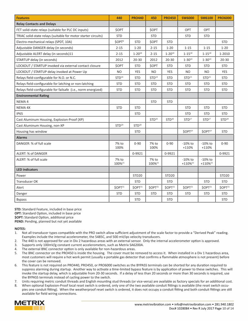
Features 440 PRO440 450 PRO450 SW6000 SM6100 PRO6000
Relay Contacts and Delays
FET solid-state relays (suitable for PLC DC inputs) $OPT $OPT OPT OPT
TRIAC solid-state relays (suitable for motor starter circuits) STD STD STD STD
Electro-mechanical relays (SPDT, 10A) $OPT9 STD $OPT STD STD
Adjustable DANGER delay (in seconds) 2-15 1-20 2-15 1-20 1-15 1-15 1-20
Adjustable ALERT delay (in seconds)11 2-15 1-2010 2-15 1-2010 1-1510 1-1510 1-2010
STARTUP delay (in seconds) 2012 20-30 2012 20-30 1-3013 1-3013 20-30
LOCKOUT / STARTUP invoked via external contact closure $OPT STD $OPT STD STD STD STD
LOCKOUT / STARTUP delay invoked at Power Up NO YES NO YES NO NO YES
Relays field-configurable for N.O. or N.C. STD14 STD STD14 STD STD15 STD15 STD
Relays field-configurable for latching or non-latching STD STD STD STD STD STD STD
Relays field-configurable for failsafe (i.e., norm energized) STD STD STD STD STD STD STD
Environmental Rating
NEMA 4 STD STD
NEMA 4X STD STD STD STD STD
IP65 STD STD STD STD
Cast Aluminum Housing, Explosion-Proof (XP) STD16 STD16 STD17 STD17 STD18
Cast Aluminum Housing, non-XP STD19 STD18
Housing has window STD $OPT27 $OPT27 STD
Alarms
DANGER: % of full scale 7% to 100%
0-90 7% to 100%
0-90 -10% to +110%
-10% to +110%
0-90
ALERT: % of DANGER 0-9921 0-9921 0-9921
ALERT: % of full scale 7% to 100%21
7% to 100%21
-10% to +110%21
-10% to +110%21
LED indicators
Power STD20 STD20 STD20
Transducer OK STD STD STD STD
Alert $OPT21 $OPT21 $OPT21 $OPT21 $OPT21 $OPT21 $OPT21
Danger STD STD STD STD STD STD STD
Bypass STD STD STD
STD: Standard Feature, included in base priceOPT: Standard Option, included in base price$OPT: Standard Option, additional pricePEND: Pending, planned but not yet available
NOTES:1. Not all transducer types compatible with the PRO switch allow sufficient adjustment of the scale factor to provide a “Derived Peak” reading.
Examples include the internal accelerometer, the 5485C, and 500 mV/ips velocity transducers.2. The 440 is not approved for use in Div 2 hazardous areas with an external sensor. Only the internal accelerometer option is approved.3. Supports only 100mV/g constant current accelerometers, such as Metrix SA6200A.4. The external BNC connector option is only available for non-hazardous areas. 5. The BNC connector on the PRO450 is inside the housing. The cover must be removed to access it. When installed in a Div 1 hazardous area,
most customers will require a hot work permit (usually a portable gas detector that confirms a flammable atmosphere is not present) before the cover can be removed.
6. This feature is not required on PRO440, PRO450, or PRO6000 switches as the BYPASS terminals can be shorted for any duration required to suppress alarming during startup. Another way to activate a time-limited bypass feature is by application of power to these switches. This will invoke the startup delay, which is adjustable from 20-30 seconds. If a delay of less than 20 seconds or more than 30 seconds is required, use the BYPASS terminals instead of cycling power to the switch.
7. Units requiring metric conduit threads and English mounting stud threads (or vice-versa) are available as factory specials for an additional cost. 8. When optional Explosion-Proof local reset switch is ordered, only one of the two available conduit fittings is available (the reset switch occu-
pies one conduit fitting). When the weatherproof reset switch is ordered, it does not occupy a conduit fitting and both conduit fittings are still available for field wiring connections.

www.metrixvibration.com • [email protected] • 281.940.1802Doc# 1028084 • Rev R July 2017 Page 11 of 14
WIRING & OUTLINE DIAGRAMS
9. Electro-mechanical relay option for 440 is only available without hazardous area approvals. Use 450, PRO440, PRO450, or PRO6000 instead when hazardous area approvals and electro-mechanical relays are required.
10. The ALERT and DANGER time delays may not be set independently; there is a single “trip delay” adjustment that governs both.11. All electronic switches listed here come with a single setpoint (DANGER) as standard. An additional setpoint (ALERT) is optional and incurs an
extra charge.12. The LOCKOUT (i.e. startup delay) feature is an optional adder on the 440 and 450. The delay duration is not adjustable and is set at the factory
for 20 seconds. LOCKOUT may only be invoked by shorting the LOCKOUT and COM wiring terminals, not by applying power to the switch. 440 and 450 switches begin monitoring immediately upon power-up and LOCKOUT must be invoked separately.
13. The SW6000 and SM6100 have a fixed 30 second delay as standard. An adjustable startup delay of 1-30 seconds is available as a chargeable option. The delay cannot be made indefinitely long by simply shorting the STARTUP and COM terminals. It will always be governed by the switch’s internal timer, regardless of whether a momentary or continuous contact closure is applied to the terminals. To re-invoke STARTUP, the terminals must first be opened. The change from OPEN to CLOSED (not CLOSED to OPEN) will initiate the STARTUP feature.
14. N.C. and N.O. slide switch available on 440 or 450 only with FET or Triac outputs – not available with electro-mechanical relays.15. When ordered with two limits (ALERT and SHUTDOWN), the relays can be individually configured for N.O. or N.C. One may be N.O. while the
other may be N.C. 16. Painted finish. Color is gray.17. Powder-coat epoxy. Color clear.18. Powder-coat epoxy. Color is Pantone 302 blue.19. Powder-coat epoxy. Color is aqua blue.20. OK LED is bi-color (green and red) to annunciate power condition. Off=No Power; Green = OK; Red=NOT OK. 21. Requires optional dual relay (DR) or dual limit version. 22. Class I Div 2 Groups B,C, and D.23. Class I Div 1 Groups B, C, and D; Class II Div 1 Groups E,F, and G; Class III24. Class I Div 1 Groups B, C, and D.25. IECEx Ex d IIB + H2 T4 (Ta = -20 to +85C w/o display; -10 to +70C w/ display).26. Class I Div 2 Groups B, C, and D; Class II Div 2 Groups E, F, and G.27. SW6000 / SM6100 models ordered with optional display have a window on the cover. Those without a display have a solid cover.
Power Input (120/220 Vac shown;
24 Vdc optional)
Relay 1 Contacts
Relay 2 Contacts (optional; absent in single relay models)
Reset
Bypass
4-20 mA output
Buffered transducer output
External transducer input (optional; absent when internal accelerometer is supplied)
Figure 1: Wiring connections on PRO switch (display removed for clarity)

www.metrixvibration.com • [email protected] • 281.940.1802Doc# 1028084 • Rev R July 2017 Page 12 of 14
Figure 2: Dimensional details of PRO440 (left) and 440 (right)
NOTE: Not to scale
PRO440 440
Aprox. Weight: 1.8 kg (4 lbs)Units: mm [in]

www.metrixvibration.com • [email protected] • 281.940.1802Doc# 1028084 • Rev R July 2017 Page 13 of 14
Aprox. Weight: 1.8 kg (4 lbs)Units: mm [in]
PRO6000 SW6000
Figure 3: Dimensional details of PRO6000 (left) and SW6000 (right)
NOTE: Not to scale

www.metrixvibration.com • [email protected] • 281.940.1802Doc# 1028084 • Rev R July 2017 Page 14 of 14
8824 Fallbrook Dr. Houston, TX 77064, USATel: 1.281.940.1802 • Fax: 1.713.559.9421
After Hours (CST) Technical Assistance: 1.713.452.9703
Figure 4: Dimensional details of PRO450 / 450
NOTE: PRO450 and 450 use identical housings
Aprox. Weight: 1.8 kg (4 lbs)Units: mm [in]