Datasheet Selector Switch Type 04
6
TYPE 04 1/6 SELECTOR SWITCH TYPE 04 › › 25'000 switching cycles with up to 20 Ncm switching torque › › Gold plated contacts: 3 micron › › Optional IP68 front panel sealing › › Operating temperature range: -40° to +85°C › › Various options and customizations MAIN FEATURES VERY ROBUST, MULTI WAFER, UP TO 24 POSITIONS 11/65/EU) PRODUCT VARIETY › ■ Soldering eyelets or pins for PCB › ■ From 1 x 24 to 6 x 3 poles x positions per wafer › ■ Up to 8 wafers › ■ Indexing angle 15° or 30° › ■ Shorting or non-shorting › ■ Switching torque 1.5, 8, 15 or 20 Ncm › ■ Front panel sealing IP60 or IP68 › ■ Configurable end-stops › ■ Shaft diameter: 6 mm or ¼" › ■ Shaft length POSSIBLE CUSTOMIZATIONS › ■ Shaft dimension and shape › ■ Bushing dimensions › ■ Switching torque › ■ Momentary contact (see page 94) › ■ Hollow shaft, inner shaft (see page 95) › ■ Others TYPICAL APPLICATIONS › ■ Industrial controls › ■ Avionics, instrumentation, test systems › ■ Medical and audio equipment › ■ Construction www.elma.com DATA SHEET 1/6 09/15
-
Upload
kathrin-fessler -
Category
Documents
-
view
243 -
download
2
description
VERY ROBUST, MULTI WAFER, UP TO 24 POSITIONS
Transcript of Datasheet Selector Switch Type 04

TYPE 04
1/6
SELECTOR SWITCH TYPE 04
›› 25'000 switching cycles with up to 20 Ncm switching torque
›› Gold plated contacts: 3 micron›› Optional IP68 front panel sealing›› Operating temperature range: -40° to +85°C›› Various options and customizations
MAIN FEATURESVERY ROBUST, MULTI WAFER, UP TO 24 POSITIONS
11/65/EU)
PRODUCT VARIETY
›■ Soldering eyelets or pins for PCB›■ From 1 x 24 to 6 x 3 poles x positions per wafer›■ Up to 8 wafers›■ Indexing angle 15° or 30°›■ Shorting or non-shorting›■ Switching torque 1.5, 8, 15 or 20 Ncm›■ Front panel sealing IP60 or IP68›■ Configurable end-stops›■ Shaft diameter: 6 mm or ¼"›■ Shaft length
POSSIBLE CUSTOMIZATIONS
›■ Shaft dimension and shape›■ Bushing dimensions›■ Switching torque›■ Momentary contact (see page 94)›■ Hollow shaft, inner shaft (see page 95)›■ Others
TYPICAL APPLICATIONS
›■ Industrial controls›■ Avionics, instrumentation, test systems›■ Medical and audio equipment›■ Construction
www.elma.com
DATA SHEET
1/609/15
2/6
SELECTOR SWITCH TYPE 04
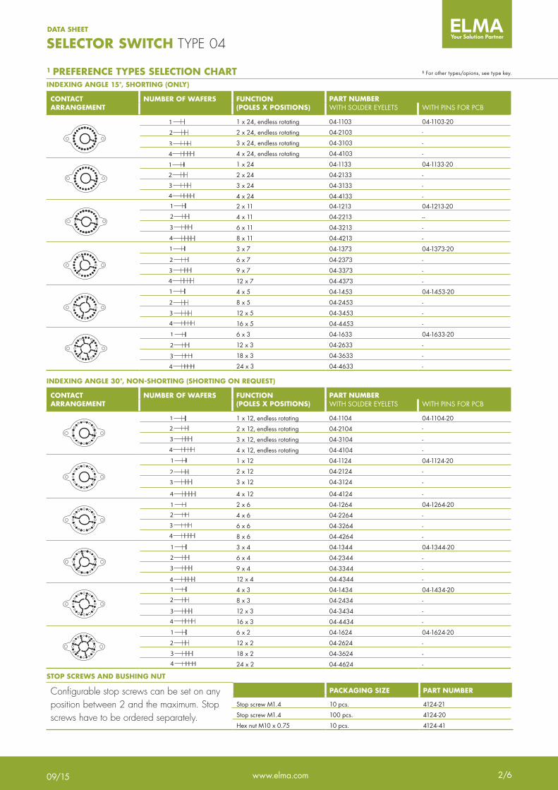
INDEXING ANGLE 15°, SHORTING (ONLY)
CONTACT ARRANGEMENT
NUMBER OF WAFERS FUNCTION(POLES X POSITIONS)
PART NUMBERWITH SOLDER EYELETS WITH PINS FOR PCB
1
2
3
4
1
2
3
4
1
2
3
4
1
2
3
4
1
2
3
4
1
2
3
4
1 x 24, endless rotating 04-1103 04-1103-201
2
3
4
1
2
3
4
1
2
3
4
1
2
3
4
1
2
3
4
1
2
3
4
2 x 24, endless rotating 04-2103 -
1
2
3
4
1
2
3
4
1
2
3
4
1
2
3
4
1
2
3
4
1
2
3
4
3 x 24, endless rotating 04-3103 -
1
2
3
4
1
2
3
4
1
2
3
4
1
2
3
4
1
2
3
4
1
2
3
4
4 x 24, endless rotating 04-4103 -
1
2
3
4
1
2
3
4
1
2
3
4
1
2
3
4
1
2
3
4
1
2
3
4
1 x 24 04-1133 04-1133-201
2
3
4
1
2
3
4
1
2
3
4
1
2
3
4
1
2
3
4
1
2
3
4
2 x 24 04-2133 -
1
2
3
4
1
2
3
4
1
2
3
4
1
2
3
4
1
2
3
4
1
2
3
4
3 x 24 04-3133 -
1
2
3
4
1
2
3
4
1
2
3
4
1
2
3
4
1
2
3
4
1
2
3
4
4 x 24 04-4133 -
1
2
3
4
1
2
3
4
1
2
3
4
1
2
3
4
1
2
3
4
1
2
3
4
2 x 11 04-1213 04-1213-201
2
3
4
1
2
3
4
1
2
3
4
1
2
3
4
1
2
3
4
1
2
3
4
4 x 11 04-2213 --
1
2
3
4
1
2
3
4
1
2
3
4
1
2
3
4
1
2
3
4
1
2
3
4
6 x 11 04-3213 -
1
2
3
4
1
2
3
4
1
2
3
4
1
2
3
4
1
2
3
4
1
2
3
4
8 x 11 04-4213 -
1
2
3
4
1
2
3
4
1
2
3
4
1
2
3
4
1
2
3
4
1
2
3
4
3 x 7 04-1373 04-1373-201
2
3
4
1
2
3
4
1
2
3
4
1
2
3
4
1
2
3
4
1
2
3
4
6 x 7 04-2373 -
1
2
3
4
1
2
3
4
1
2
3
4
1
2
3
4
1
2
3
4
1
2
3
4
9 x 7 04-3373 -
1
2
3
4
1
2
3
4
1
2
3
4
1
2
3
4
1
2
3
4
1
2
3
4
12 x 7 04-4373 -
1
2
3
4
1
2
3
4
1
2
3
4
1
2
3
4
1
2
3
4
1
2
3
4
4 x 5 04-1453 04-1453-201
2
3
4
1
2
3
4
1
2
3
4
1
2
3
4
1
2
3
4
1
2
3
4
8 x 5 04-2453 -
1
2
3
4
1
2
3
4
1
2
3
4
1
2
3
4
1
2
3
4
1
2
3
4
12 x 5 04-3453 -
1
2
3
4
1
2
3
4
1
2
3
4
1
2
3
4
1
2
3
4
1
2
3
4
16 x 5 04-4453 -
1
2
3
4
1
2
3
4
1
2
3
4
1
2
3
4
1
2
3
4
1
2
3
4
6 x 3 04-1633 04-1633-201
2
3
4
1
2
3
4
1
2
3
4
1
2
3
4
1
2
3
4
1
2
3
4
12 x 3 04-2633 -
1
2
3
4
1
2
3
4
1
2
3
4
1
2
3
4
1
2
3
4
1
2
3
4
18 x 3 04-3633 -
1
2
3
4
1
2
3
4
1
2
3
4
1
2
3
4
1
2
3
4
1
2
3
4
24 x 3 04-4633 -
1 PREFERENCE TYPES SELECTION CHART 1 For other types/opions, see type key.
INDEXING ANGLE 30°, NON-SHORTING (SHORTING ON REQUEST)
CONTACT ARRANGEMENT
NUMBER OF WAFERS FUNCTION(POLES X POSITIONS)
PART NUMBERWITH SOLDER EYELETS WITH PINS FOR PCB
1
2
3
4
1
2
3
4
1
2
3
4
1
2
3
4
1
2
3
4
1
2
3
4
1 x 12, endless rotating 04-1104 04-1104-201
2
3
4
1
2
3
4
1
2
3
4
1
2
3
4
1
2
3
4
1
2
3
4
2 x 12, endless rotating 04-2104 -
1
2
3
4
1
2
3
4
1
2
3
4
1
2
3
4
1
2
3
4
1
2
3
4
3 x 12, endless rotating 04-3104 -
1
2
3
4
1
2
3
4
1
2
3
4
1
2
3
4
1
2
3
4
1
2
3
4
4 x 12, endless rotating 04-4104 -
1
2
3
4
1
2
3
4
1
2
3
4
1
2
3
4
1
2
3
4
1
2
3
4
1 x 12 04-1124 04-1124-201
2
3
4
1
2
3
4
1
2
3
4
1
2
3
4
1
2
3
4
1
2
3
4
2 x 12 04-2124 -
1
2
3
4
1
2
3
4
1
2
3
4
1
2
3
4
1
2
3
4
1
2
3
4
3 x 12 04-3124 -
1
2
3
4
1
2
3
4
1
2
3
4
1
2
3
4
1
2
3
4
1
2
3
4
4 x 12 04-4124 -
1
2
3
4
1
2
3
4
1
2
3
4
1
2
3
4
1
2
3
4
1
2
3
4
2 x 6 04-1264 04-1264-201
2
3
4
1
2
3
4
1
2
3
4
1
2
3
4
1
2
3
4
1
2
3
4
4 x 6 04-2264 -
1
2
3
4
1
2
3
4
1
2
3
4
1
2
3
4
1
2
3
4
1
2
3
4
6 x 6 04-3264 -
1
2
3
4
1
2
3
4
1
2
3
4
1
2
3
4
1
2
3
4
1
2
3
4
8 x 6 04-4264 -
1
2
3
4
1
2
3
4
1
2
3
4
1
2
3
4
1
2
3
4
1
2
3
4
3 x 4 04-1344 04-1344-201
2
3
4
1
2
3
4
1
2
3
4
1
2
3
4
1
2
3
4
1
2
3
4
6 x 4 04-2344 -
1
2
3
4
1
2
3
4
1
2
3
4
1
2
3
4
1
2
3
4
1
2
3
4
9 x 4 04-3344 -
1
2
3
4
1
2
3
4
1
2
3
4
1
2
3
4
1
2
3
4
1
2
3
4
12 x 4 04-4344 -
1
2
3
4
1
2
3
4
1
2
3
4
1
2
3
4
1
2
3
4
1
2
3
4
4 x 3 04-1434 04-1434-201
2
3
4
1
2
3
4
1
2
3
4
1
2
3
4
1
2
3
4
1
2
3
4
8 x 3 04-2434 -
1
2
3
4
1
2
3
4
1
2
3
4
1
2
3
4
1
2
3
4
1
2
3
4
12 x 3 04-3434 -
1
2
3
4
1
2
3
4
1
2
3
4
1
2
3
4
1
2
3
4
1
2
3
4
16 x 3 04-4434 -
1
2
3
4
1
2
3
4
1
2
3
4
1
2
3
4
1
2
3
4
1
2
3
4
6 x 2 04-1624 04-1624-201
2
3
4
1
2
3
4
1
2
3
4
1
2
3
4
1
2
3
4
1
2
3
4
12 x 2 04-2624 -
1
2
3
4
1
2
3
4
1
2
3
4
1
2
3
4
1
2
3
4
1
2
3
4
18 x 2 04-3624 -
1
2
3
4
1
2
3
4
1
2
3
4
1
2
3
4
1
2
3
4
1
2
3
4
24 x 2 04-4624 -
STOP SCREWS AND BUSHING NUT
Configurable stop screws can be set on any position between 2 and the maximum. Stop screws have to be ordered separately.
PACKAGING SIZE PART NUMBER
Stop screw M1.4 10 pcs. 4124-21
Stop screw M1.4 100 pcs. 4124-20
Hex nut M10 x 0.75 10 pcs. 4124-41
www.elma.com
DATA SHEET
2/609/15
3/6
SELECTOR SWITCH TYPE 04
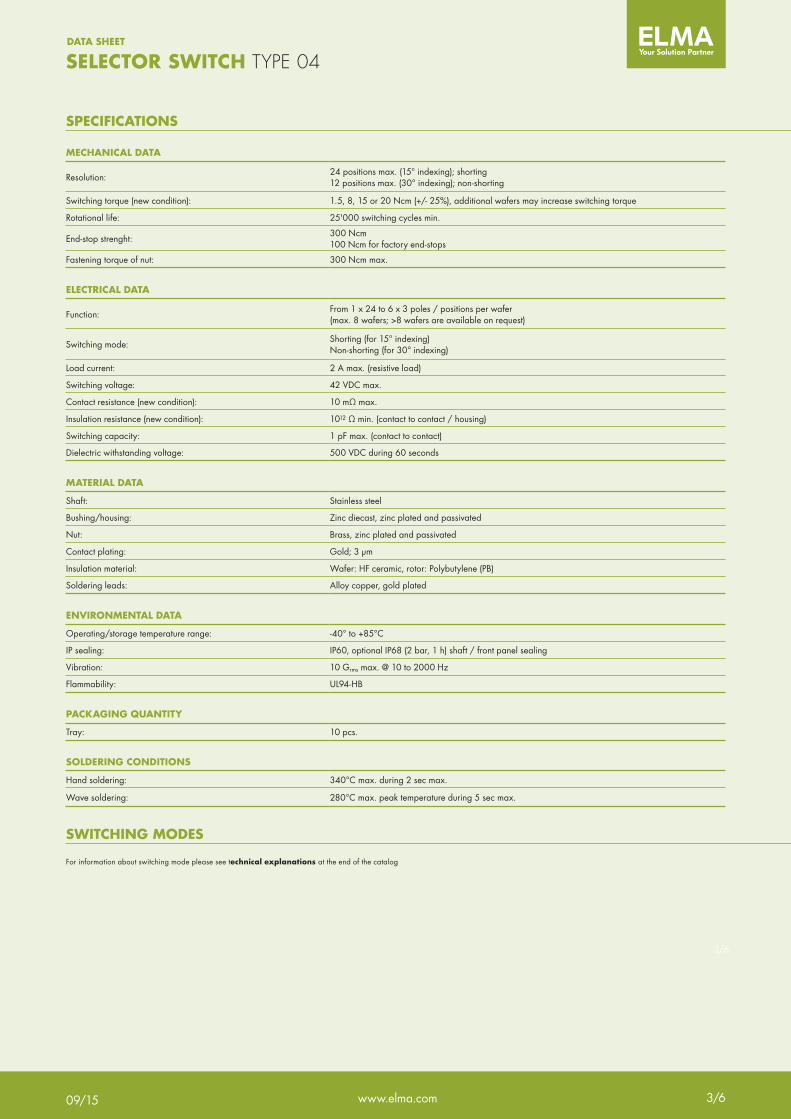
MECHANICAL DATA
Resolution:24 positions max. (15° indexing); shorting12 positions max. (30° indexing); non-shorting
Switching torque (new condition): 1.5, 8, 15 or 20 Ncm (+/- 25%), additional wafers may increase switching torque
Rotational life: 25'000 switching cycles min.
End-stop strenght:300 Ncm100 Ncm for factory end-stops
Fastening torque of nut: 300 Ncm max.
ELECTRICAL DATA
Function:From 1 x 24 to 6 x 3 poles / positions per wafer(max. 8 wafers; >8 wafers are available on request)
Switching mode:Shorting (for 15° indexing) Non-shorting (for 30° indexing)
Load current: 2 A max. (resistive load)
Switching voltage: 42 VDC max.
Contact resistance (new condition): 10 mΩ max.
Insulation resistance (new condition): 1012 Ω min. (contact to contact / housing)
Switching capacity: 1 pF max. (contact to contact)
Dielectric withstanding voltage: 500 VDC during 60 seconds
MATERIAL DATA
Shaft: Stainless steel
Bushing/housing: Zinc diecast, zinc plated and passivated
Nut: Brass, zinc plated and passivated
Contact plating: Gold; 3 µm
Insulation material: Wafer: HF ceramic, rotor: Polybutylene (PB)
Soldering leads: Alloy copper, gold plated
ENVIRONMENTAL DATA
Operating/storage temperature range: -40° to +85°C
IP sealing: IP60, optional IP68 (2 bar, 1 h) shaft / front panel sealing
Vibration: 10 Grms max. @ 10 to 2000 Hz
Flammability: UL94-HB
PACKAGING QUANTITY
Tray: 10 pcs.
SOLDERING CONDITIONS
Hand soldering: 340°C max. during 2 sec max.
Wave soldering: 280°C max. peak temperature during 5 sec max.
SPECIFICATIONS
SWITCHING MODES
For information about switching mode please see technical explanations at the end of the catalog
www.elma.com
DATA SHEET
3/609/15
1C 2C3C
4C
1A
2A3A4A
1B
2B
3B
4B
3x4°3x120°
°15°
1E 2E1F
2F
1A
2A1B2B
1C
2C
1D
2D
°6x60°°15°
6x2
9 1011
12
1
234
5
6
7
8
°30°
°45°
°12,5
°
1x12
3B 4B5B
6B
1A
2A3A4A
5A
6A
1B
2B
2x6
°15°
3C 1D2D
3D
1A
2A3A1B
2B
3B
1C
2C
4x3°4x90°
°15°
= ø1,3mm= ø2,3mm
4/6
SELECTOR SWITCH TYPE 04
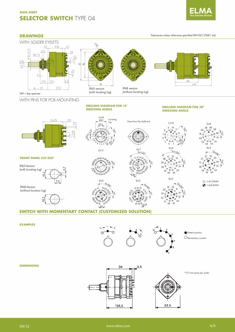
DRAWINGSWITH SOLDER EYELETS
WITH PINS FOR PCB MOUNTING
FRONT PANEL CUT OUT
DRILLING DIAGRAM FOR 15° INDEXING ANGLE
DRILLING DIAGRAM FOR 30° INDEXING ANGLE
SWITCH WITH MOMENTARY CONTACT (CUSTOMIZED SOLUTION)
EXAMPLES
DIMENSIONS
SW = key spanner
24,1
14,3Verdreh-schutz
°2,5
°
15°
30°
°45°
12,5
°
1819 2021
2223
1110
98 7 6 5 4 3
21
13
151716
14
12
A
24
1x24Ansicht des Bohr-
planes von der Schalterachse her
3C
2F3F
2C
1F
1C
3E2E1E
3B 2B1B3A
3D
2A
2D
1A1D
AB
C
D E
F
30°
6x60°15°
6x3
3B
7C
2B
6C
1B
5C4C
7A
3C
6A
2C
5A
1C
4A3A
7B
2A
6B
1A5B
30°
3x120°
15°
3x7
15°
11A
11B
10A
10B
9A
9B
8A
8B
7A
7B
6A
6B
5A
5B
4A
4B
3A
3B
2A
2B
1A1B B
A
2x11
1819 2021
2223
1110
98 7 6 5 4 3
21
13
151716
1412 A
1x23
5B
5D
4B
4D
3B
3D
2B
2D
1B
1D
5A
5C
4A
4C
3A
3C
2A
2C
1A1C
BC D
A
30°
4x90°15°
4x5
1
B C4B
A
Locatinglug View from the shaft end
*17.5 mm extra per wafer
Detent position
Momentary contact
Tolerances unless otherwise specified DIN ISO 2768-1 (m)
IP68 version (without locating lug)
IP60 version (with locating lug)
10,2
7,5
2,7
10,2
IP68-Version (without location lug)
IP60-Version (with locating lug)
www.elma.com
DATA SHEET
4/609/15
5/6
SELECTOR SWITCH TYPE 04
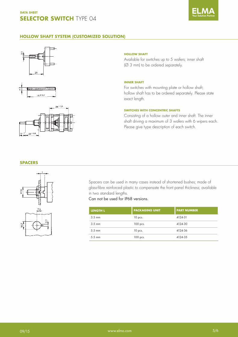
HOLLOW SHAFT SYSTEM (CUSTOMIZED SOLUTION)
SPACERS
HOLLOW SHAFT
Available for switches up to 5 wafers; inner shaft (Ø 3 mm) to be ordered separately.
INNER SHAFT
For switches with mounting plate or hollow shaft; hollow shaft has to be ordered separately. Please state exact length.
SWITCHES WITH CONCENTRIC SHAFTS
Consisting of a hollow outer and inner shaft. The inner shaft driving a maximum of 3 wafers with 6 wipers each. Please give type description of each switch.
Spacers can be used in many cases instead of shortened bushes; made of glass-fibre reinforced plastic to compensate the front panel thickness; available in two standard lengths.Can not be used for IP68 versions.
LENGTH L PACKAGING UNIT PART NUMBER
3.5 mm 10 pcs. 4124-31
3.5 mm 100 pcs. 4124-30
5.5 mm 10 pcs. 4124-36
5.5 mm 100 pcs. 4124-35
www.elma.com
DATA SHEET
5/609/15

6/6
SELECTOR SWITCH TYPE 04
(see page 92)
PART NUMBER
(max. 8) > 8 on request
NUMBER OF WAFERS
Number of Poles per Wafer
NUMBER OF POLES
Defined by Elma(See page 92, is composed of switching mode, poles and positions)
FACTORY SET CHARACTER
0 6 mm (standard)Z ¼"
SHAFT DIAMETER
00 24 pos. (standard)23 23 pos.22 22 pos.21 21 pos.20 20 pos.19 19 pos.18 18 pos.17 17 pos.16 16 pos.15 15 pos.14 14 pos.13 13 pos.12 12 pos.11 11 pos.10 10 pos.09 9 pos.08 8 pos.07 7 pos.06 6 pos.05 5 pos.04 4 pos.03 3 pos02 2 pos.
FACTORY SET END-STOP
000 25 mm (standard)1 xxx Custom (e.g. 18.5 mm = 185)
1 Customized shaft lengthShaft length (AL) description measured from mounting face (see picture below).
Max shaft length (AL): Ø ¼" = 25 mm Ø 6 mm = 50 mm
SHAFT LENGTH (AL)
00 Eyelets, IP6020 Pins for PCB, IP60 30 Eyelets; IP6870 Pins for PCB; IP68
PIN STYLE; IP SEALING
04 – _ _ _ _ – _ _ _ _ _ _ _ _
TYPE KEY
- HF ceramic
WAFER TYPE
- 15 Ncm (standard)M 8 NcmN 20 NcmR 1.5 Ncm
TORQUE
3 Shorting4 Non-shorting (not for 15° index. angle)
SWITCHING MODE
AL
www.elma.com
DATA SHEET
6/609/15