PRO MATE II Device Support - Farnell element14 · PRO MATE® II DEVICE SUPORT 1999 Microchip...
48
PRO MATE ® II DEVICE SUPORT 1999 Microchip Technology Inc. DS30243H Information contained in this publication regarding device applications and the like is intended by way of suggestion only. No representation or warranty is given and no liability is assumed by Microchip Technology Incorporated with respect to the accuracy or use of such information. Use of Microchip’s products as critical components in life support systems is not authorized except with express written approval by Microchip. 1999 Microchip Technology Incorporated. All rights reserved. The Microchip logo and name, PIC, PICmicro, PICMASTER, PRO MATE, and KEELEOQ are registered rademarks of Microchip Technology Incorporated in the U.S.A. and other countries. MPLAB, and Smart Serial are trademarks of Microchip Technology in the U.S.A. and other countries. All product/company trademarks mentioned herein are the property of their respective companies.
-
Upload
phungtuyen -
Category
Documents
-
view
220 -
download
0
Transcript of PRO MATE II Device Support - Farnell element14 · PRO MATE® II DEVICE SUPORT 1999 Microchip...
PRO MATE® II DEVICE SUPORT
Information contained in this publication regarding device applications and the like is intended by way of suggestiononly. No representation or warranty is given and no liability is assumed by Microchip Technology Incorporated withrespect to the accuracy or use of such information. Use of Microchip’s products as critical components in life supportsystems is not authorized except with express written approval by Microchip.
1999 Microchip Technology Incorporated. All rights reserved.
The Microchip logo and name, PIC, PICmicro, PICMASTER, PRO MATE, and KEELEOQ are registered rademarks ofMicrochip Technology Incorporated in the U.S.A. and other countries. MPLAB, and Smart Serial are trademarks of Microchip Technology in the U.S.A. and other countries.
All product/company trademarks mentioned herein are the property of their respective companies.
1999 Microchip Technology Inc. DS30243H

PRO MATE® II Device Support
DS30243H 1999 Microchip Technology Inc.
PRO MATE® II DEVICE SUPPORT
Table of Contents
General InformationIntroduction .......................................................................................... 1
Highlights ............................................................................................. 1
About This Guide ................................................................................. 1
Recommended Reading ...................................................................... 3
The Microchip Internet Web Site .......................................................... 4
Development Systems Customer Notification Service ......................... 5
Customer Support ................................................................................ 7
Chapter 1. Socket Modules1.1 Introduction ................................................................................ 9
1.2 Highlights ................................................................................... 9
1.3 Currently Supported Devices and Socket Modules ................... 9
1.4 Socket Life Expectancy and Cleaning Procedures .................. 13
Chapter 2. Programming Devices with Calibration
2.1 Introduction .............................................................................. 15
2.2 Highlights ................................................................................. 15
2.3 Programmer Dialogs ................................................................ 16
2.4 Calibration Windows ................................................................ 17
Chapter 3. Programming KEELOQ® Devices3.1 Introduction .............................................................................. 19
3.2 Highlights ................................................................................. 19
3.3 Programming Overview ........................................................... 19
3.4 Key Generation ........................................................................ 21
3.5 Manufacturer’s Code ............................................................... 22
3.6 HCS200 Options ...................................................................... 24
3.7 HCS201 Options ...................................................................... 25
3.8 HCS300/301/320 Options ........................................................ 26
1999 Microchip Technology Inc. DS30243G1-page iii
PRO MATE® II Device Support
3.9 HCS360 Options ......................................................................28
3.10 HCS361 Options ......................................................................30
3.11 HCS410 Options ......................................................................32
3.12 HCS412 Options ......................................................................35
3.13 HCS512 Options ......................................................................38
Chapter 4. Programming Memory Devices4.1 Introduction ..............................................................................39
4.2 Highlights .................................................................................39
4.3 Programming Overview – Memory Devices .............................39
Index.......................................................................................................... 41
Worldwide Sales and Service.................................................................. 44
DS30243G1-page iv 1999 Microchip Technology Inc.
®
PRO MATE II DEVICE SUPPORTGeneral Information
IntroductionThis chapter contains general information that will be useful to know before using this document.
HighlightsThe information you will garner from this chapter:
• About this Guide
• Recommended Reading
• The Microchip Internet Website
• Development Systems Customer Notification Service
• Customer Support
About This Guide
Document LayoutThis document describes how to use PRO MATE II as a development tool to program firmware to a target device. The manual layout is as follows:
• Chapter 1: Socket Modules – Lists the part numbers for the socket modules that support each device and discusses the life expectancy and cleaning procedures for the different socket types.
• Chapter 2: Programming Devices with Calibration – How to program PIC12CXXX, PIC14C000, and PIC16C505 devices.
• Chapter 3: Programming KEELOQ® Devices – How to program KEELOQ devices.
• Chapter 4: Programming Memory Devices – How to program mem-ory devices.
• Index – Cross-reference listing of terms, features, and sections of this document.
• Worldwide Sales and Service – A listing of Microchip sales and service locations, and telephone numbers worldwide.
1999 Microchip Technology Inc. DS30243G1-page 1

PRO MATE® II Device Support
Conventions Used in this GuideThis manual uses the following documentation conventions:
UpdatesAll documentation becomes dated, and this device specification is no exception. Since MPLAB, PRO MATE II and other Microchip tools are constantly evolving to meet customer needs, some MPLAB dialogs and/or tool descriptions may differ from those in this document. Please refer to our web site to obtain the latest documentation available.
Documentation Conventions
Description Represents Examples
Angle Brackets: < > Delimiters for special keys. <TAB>, <ESC>
Italic characters Referenced books. MPLAB™ User’s Guide
Courier Font User entered code or sample code.
#define ENIGMA
Underlined, Italics Text with Right Arrow
Defines a menu selection from the menu bar.
File > Save
0xnnn 0xnnn represents a hexadeci-mal number where n is a hexa-decimal digit.
0xFFFF, 0x007A
In-text Bold Characters Designates a button. OK, Cancel
DS30243G1-page 2 1999 Microchip Technology Inc.
General Information
Recommended ReadingThis document describes PRO MATE II socket modules and device-specific programming options. For more information on using the PRO MATE II and general programming procedures, please refer to the PRO MATE II User’s Guide. For the latest PRO MATE II information, please refer to the README.PRO file.
README.PRO
For the latest information on PRO MATE II, read the README.PRO file (ASCII text file) included with the PRO MATE II software. This README file contains update information that may not be included in this document.
PRO MATE II User’s Guide (DS30028)
This user’s guide describes how to set up and use PRO MATE II. General programming procedures are detailed for PICmicro®, KEELOQ and memory devices.
MPLAB User’s Guide (DS51025)
Comprehensive guide that describes installation and features of Microchip’s MPLAB Integrated Development Environment, as well as the editor and simulator functions in the MPLAB environment.
Technical Library CD-ROM (DS00161)
This CD-ROM contains comprehensive data sheets for Microchip PICmicro devices available at the time of print. To obtain this disk, contact the nearest Microchip Sales and Service location (see back page) or download individual data sheet files from the Microchip website (http://www.microchip.com).
Embedded Control Handbook Vol.1 & 2 (DS00092 & DS00167)
These handbooks contain a wealth of information about microcontroller applications. To obtain these documents, contact the nearest Microchip Sales and Service location (see back page).
The application notes described in these manuals are also obtainable from Microchip Sales and Service locations or from the Microchip web site (http://www.microchip.com).
Microsoft Windows Manuals
Microchip software documentation assumes that you are familiar with the Microsoft Windows operating system. Many excellent references exist for this software program, and should be consulted for general operation of Windows.
1999 Microchip Technology Inc. DS30243G1-page 3

PRO MATE® II Device Support
The Microchip Internet Web SiteMicrochip provides on-line support on the Microchip World Wide Web (WWW)site.
The web site is used by Microchip as a means to make files and informationeasily available to customers. To view the site, the user must have access tothe Internet and a web browser, such as Netscape® Communicator orMicrosoft® Internet Explorer®. Files are also available for FTP download fromour FTP site.
Connecting to the Microchip Internet Web Site
The Microchip web site is available by using your favorite Internet browserto attach to:
http://www.microchip.com
The file transfer site is available by using an FTP program/client to connect to:
ftp://ftp.microchip.com
The web site and file transfer site provide a variety of services. Users maydownload files for the latest Development Tools, Data Sheets, ApplicationNotes, User’s Guides, Articles, and Sample Programs. A variety of Microchipspecific business information is also available, including listings of Microchipsales offices, distributors, and factory representatives. Other data available forconsideration is:
• Latest Microchip Press Releases• Technical Support Section with Frequently Asked Questions • Design Tips• Device Errata• Job Postings• Microchip Consultant Program Member Listing• Links to other useful web sites related to Microchip Products• Conferences for products, Development Systems, technical information,
and more• Listing of seminars and events
DS30243G1-page 4 1999 Microchip Technology Inc.
General Information
Development Systems Customer Notification ServiceMicrochip started the customer notification service to help our customers keep current on Microchip products with the least amount of effort. Once you subscribe to one of our list servers, you will receive email notification whenever we change, update, revise or have errata related to that product family or development tool. See the Microchip WWW page for other Microchip list servers.
The Development Systems list names are:
• Compilers
• Emulators
• Programmers
• MPLAB
• Otools.
Once you have determined the names of the lists that you are interested in, you can subscribe by sending a message to:
with the following as the body:
subscribe <listname> yourname
Here is an example:
subscribe programmers John Doe
To UNSUBSCRIBE from these lists, send a message to:
with the following as the body:
unsubscribe <listname> yourname
Here is an example:
unsubscribe programmers John Doe
The following sections provide descriptions of the available Development Systems lists.
CompilersThe latest information on Microchip C compilers, Linkers and Assemblers. These include MPLAB-C17, MPLAB-C18, MPLINK, MPASM as well as the Librarian, MPLIB for MPLINK.
To SUBSCRIBE to this list, send a message to:
with the following as the body:
subscribe compilers yourname
1999 Microchip Technology Inc. DS30243G1-page 5
PRO MATE® II Device Support
EmulatorsThe latest information on Microchip In-Circuit Emulators. These include MPLAB-ICE and PICMASTER®.
To SUBSCRIBE to this list, send a message to:
with the following as the body:
subscribe emulators yourname
ProgrammersThe latest information on Microchip PICmicro device programmers. These include PRO MATE II and PICSTART Plus.
To SUBSCRIBE to this list, send a message to:
with the following as the body:
subscribe programmers yourname
MPLABThe latest information on Microchip MPLAB, the Windows Integrated Development Environment for development systems tools. This list is focused on MPLAB, MPLAB-SIM, MPLAB’s Project Manager and general editing and debugging features. For specific information on MPLAB compilers, linkers and assemblers, subscribe to the COMPILERS list. For specific information on MPLAB emulators, subscribe to the EMULATORS list. For specific information on MPLAB device programmers, please subscribe to the PROGRAMMERS list.
To SUBSCRIBE to this list, send a message to:
with the following as the body:
subscribe mplab yourname
OtoolsThe latest information on other development system tools provided by Microchip. For specific information on MPLAB and its integrated tools refer to the other mail lists.
To SUBSCRIBE to this list, send a message to:
with the following as the body:
subscribe otools yourname
DS30243G1-page 6 1999 Microchip Technology Inc.

General Information
Customer SupportUsers of Microchip products can receive assistance through several channels:
• Distributor or Representative
• Local Sales Office
• Field Application Engineer (FAE)
• Corporate Applications Engineer (CAE)
• Hot line
Customers should call their distributor, representative, or field application engineer (FAE) for support. Local sales offices are also available to help customers. See the back cover for a listing of sales offices and locations.
Corporate applications engineers (CAEs) may be contacted at (480) 786-7627.
In addition, there is a Systems Information and Upgrade Line. This line provides system users a listing of the latest versions of all of Microchip's development systems software products. Plus, this line provides information on how customers can receive any currently available upgrade kits.
The Hot Line Numbers are:
1-800-755-2345 for U.S. and most of Canada, and
1-480-786-7302 for the rest of the world.
1999 Microchip Technology Inc. DS30243G1-page 7

PRO MATE® II Device Support
NOTES:
DS30243G1-page 8 1999 Microchip Technology Inc.
®
PRO MATE II DEVICE SUPPORTChapter 1. Socket Modules
1.1 IntroductionThis chapter lists the part numbers for the socket modules that support each device and discusses the life expectancy and cleaning procedures for the different socket types. These sockets work on both PRO MATE and PRO MATE II. For socket modules with two sets of screws, the longer screws are for PRO MATE and the shorter screws are for PRO MATE II.
1.2 HighlightsThe topics covered in this chapter are:
• Currently Supported Devices and Socket Modules
• Socket Life Expectancy and Cleaning Procedures
1.3 Currently Supported Devices and Socket Modules
Table 1.1 defines the acronyms for the microcontroller device packages. Table 1.2 lists the part numbers for the socket modules that support each device.
Table: 1.1 Device Package Names
DIP Dual Inline Package PLCC Plastic Leaded Chip Carrier
SOIC Small Outline Integrated Circuit MQFP Metric Quad Flat Pack
SSOP Shrink Small Outline Package TQFP Thin Quad Flat Pack
1999 Microchip Technology Inc. DS30243H-page 9

PRO MATE® II Device Support
Table: 1.2 Socket Module and Supported Devices Cross-Reference
Model Name/Part Number
PinCount
DIP SOIC SSOP PLCC MQFP TQFP
24CXX/24LCXX
8 AC004001 AC004002 — — — —
93CXX/93LCXX
8 AC004001 AC004002 — — — —
HCS200 8 AC004001 AC004002 — — — —HCS201 8 AC004001 AC004002 — — — —HCS300 8 AC004001 AC004002 — — — —HCS301 8 AC004001 AC004002 — — — —HCS320 8 AC004001 AC004002 — — — —HCS360 8 AC004001 AC004002 — — — —HCS361 8 AC004001 AC004002 — — — —HCS410 8 AC004001 — — — — —HCS412 8 AC004001 AC164002 — — — —HCS512 8 AC164001 — — — — —PIC12C508 8 AC124001 AC124001 — — — —PIC12C508A 8 AC124001 AC124001 — — — —PIC12C509 8 AC124001 AC124001 — — — —PIC12C509A 8 AC124001 AC124001 — — — —PIC12CE518 8 AC124001 AC124001 AC164026 — — —PIC12CE519 8 AC124001 AC124001 AC164026 — — —PIC12C671 8 AC124001 AC124001 — — — —PIC12C672 8 AC124001 AC124001 — — — —PIC12EC673 8 AC124001 AC124001 — — — —PIC12EC674 8 AC124001 AC124001 — — — —PIC14C000 28 AC144001 AC144002 AC124002 — — —PIC16C505 14 AC124001 AC164026 — — — —PIC16C52 18/20 AC164001 AV164002 AC164015 — — —PIC16C54 18/20 AC164001 AV164002 AC164015 — — —PIC16C54A 18/20 AC164001 AV164002 AC164015 — — —PIC16C54B 18/20 AC164001 AV164002 AC164015 — — —PIC16C54C 18/20 AC164001 AV164002 AC164015 — — —PIC16C55 28 AC164001 AV164002 AC164015 — — —PIC16C55A 28 AC164001 AV164002 AC164015 — — —PIC16C554 18/20 AC164010 AC164010 AC164018 — — —PIC16C558 18/20 AC164010 AC164010 AC164018 — — —PIC16C56 18/20 AC164001 AC164002 AC164015 — — —PIC16C56A 18/20 AC164001 AC164002 AC164015 — — —
Shaded area indicates not applicable.* When using a 28-pin device in a 40-pin socket, align pin 1 to the pin 1 indicator (socket is top justified).
DS30243H-page 10 1999 Microchip Technology Inc.

Chapter 1. Socket Modules
PIC16C57 28 AC164001 AC164002 AC164015 — — —PIC16C57C 28 AC164001 AC164002 AC164015 — — —PIC16C58A 18/20 AC164001 AC164002 AC164015 — — —PIC16C58B 18/20 AC164001 AC164002 AC164015 — — —PIC16C62A 28 AC164012 AC164017 AC164021 — — —PIC16C62B 28 AC164012 AC164017 AC164021 — — —PIC16C620 18/20 AC164010 AC164010 AC164018 — — —PIC16C620A 18/20 AC164010 AC164010 AC164018 — — —PIC16C621 18/20 AC164010 AC164010 AC164018 — — —PIC16C621A 18/20 AC164010 AC164010 AC164018 — — —PIC16C622 18/20 AC164010 AC164010 AC164018 — — —PIC16C622A 18/20 AC164010 AC164010 AC164018 — — —PIC16CE623 18/20 AC164010 AC164010 AC164018 — — —PIC16CE624 18/20 AC164010 AC164010 AC164018 — — —PIC16CE625 18/20 AC164010 AC164010 AC164018 — — —PIC16C63 28 AC164012 AC164017 — — — —PIC16C63A 28 AC164012 AC164017 — — — —PIC16C64A 40/44 AC164012 — — AC164013 AC164014 AC164020PIC16C642 28 AC164012 AC164017 — — — —PIC16C65A 40/44 AC164012 — — AC164013 AC164014 AC164020PIC16C65B 40/44 AC164012 — — AC164013 AC164014 AC164020PIC16C66 28 AC164012 AC164017 — — — —PIC16C662 40/44 AC164012 — — AC164013 AC164014 AC164020PIC16C67 40/44 AC164012 — — AC164013 AC164014 AC164020PIC16C71 18 AC164010 AC164010 — — — —PIC16C710 18 AC164010 AC164010 AC164018 — — —PIC16C711 18 AC164010 AC164010 AC164018 — — —PIC16C715 18 AC164010 AC164010 AC164018 — — —PIC16C72 28 AC164012 AC164017 AC164021 — — —PIC16C72A 28 AC164012 AC164017 AC164021 — — —PIC16C73A 28 AC164012 AC164017 — — — —PIC16C73B 28 AC164012 AC164017 — — — —PIC16C74A 40/44 AC164012 — — AC164013 AC164014 AC164020PIC16C74B 40/44 AC164012 — — AC164013 AC164014 AC164020PIC16C76 28 AC164012 AC164017 — — — —PIC16C77 40/44 AC164012 — — AC164013 AC164014 AC164020PIC16C773 28 AC164012 AC164017 AC164021 — — —PIC16C774 40/44 AC164012 — — AC164013 — AC164020
Model Name/Part Number
PinCount
DIP SOIC SSOP PLCC MQFP TQFP
Shaded area indicates not applicable.* When using a 28-pin device in a 40-pin socket, align pin 1 to the pin 1 indicator (socket is top justified).
1999 Microchip Technology Inc. DS30243H-page 11

PRO MATE® II Device Support
PIC16F83 18 AC164010 AC164010 — — — —PIC16F84 18 AC164010 AC164010 — — — —PIC16F84A 18 AC164010 AC164010 — — — —PIC16F877 40/44 AC164012 — — AC164013 — AC164020PIC16C923 64/68 AC164025 — — AC164022 — AC164023PIC16C924 64/68 AC164025 — — AC164022 — AC164023PIC17C42A 40/44 AC174001 — — AC174002 AC174004 AC174005PIC17C43 40/44 AC174001 — — AC174002 AC174004 AC174005PIC17C44 40/44 AC174001 — — AC174002 AC174004 AC174005PIC17C752 64/68 AC174009 — — AC174007 — AC174008PIC17C756 64/68 AC174009 — — AC174007 — AC174008PIC17C756A 64/68 AC174009 — — AC174007 — AC174008PIC17C762 80/84 — — — AC174012 — AC174011PIC17C766 80/84 — — — AC174012 — AC174011
Model Name/Part Number
PinCount
DIP SOIC SSOP PLCC MQFP TQFP
Shaded area indicates not applicable.* When using a 28-pin device in a 40-pin socket, align pin 1 to the pin 1 indicator (socket is top justified).
DS30243H-page 12 1999 Microchip Technology Inc.

Chapter 1. Socket Modules
1.4 Socket Life Expectancy and Cleaning Procedures
Microchip uses socket modules from several manufacturers. Table 1.3 gives the expected life (in number of automatic insertions) and cleaning method for each socket module as reported by the manufacturer.
1.4.1 ManufacturerLook at the socket module to determine the name of the manufacturer. The Yamaichi socket is not labeled; identify a Yamaichi socket by looking for the letters IC51– (as the prefix to a part number) on the socket.
1.4.2 InsertionsThe expected life for manual insertions has been found to be less than the manufacturer’s reported number. The number of manual insertions depends on the socket condition and how often the socket is cleaned.
Careless insertions or dirty socket conditions can bring the number of insertions down to less than 5,000. Cleanliness and care in inserting devices into a socket are most important with surface mount devices as the socket contactors must remain planar to function properly.
Any bent or nonplanar contacts will result in a failure. Nonplanar socket module contacts occur earlier in the life of a socket module when devices are inserted manually into a socket module. Early contact failure from manual insertions is due to the nonrepeatability of the manual insertion method. Therefore, the listed number of insertions may not be reached for sockets where devices are inserted manually. No good method exists to ensure that the contacts are planar.
Table: 1.3 Socket Life Expectancy and Cleaning Method
Manufacturer Insertions Cleaning Method
Aries (28 pin) 10,000 #2
AMP (18 pin) 25,000 #2
3M Textool 10,000 #1
AMP (Dip) 25,000 #2
3M Textool (SOIC) 10,000 #1
Aries 10,000 #2
Yamaichi 25,000 #1
1999 Microchip Technology Inc. DS30243H-page 13
PRO MATE® II Device Support
1.4.3 Cleaning MethodMethod #1 – Methyl Alcohol
Clean with methyl alcohol, and then blow off the contacts with dry compressed air.
Method #2 – Not Recommended
There is no cleaning procedure for this socket type. If contacts get extremely contaminated, replace the socket module.
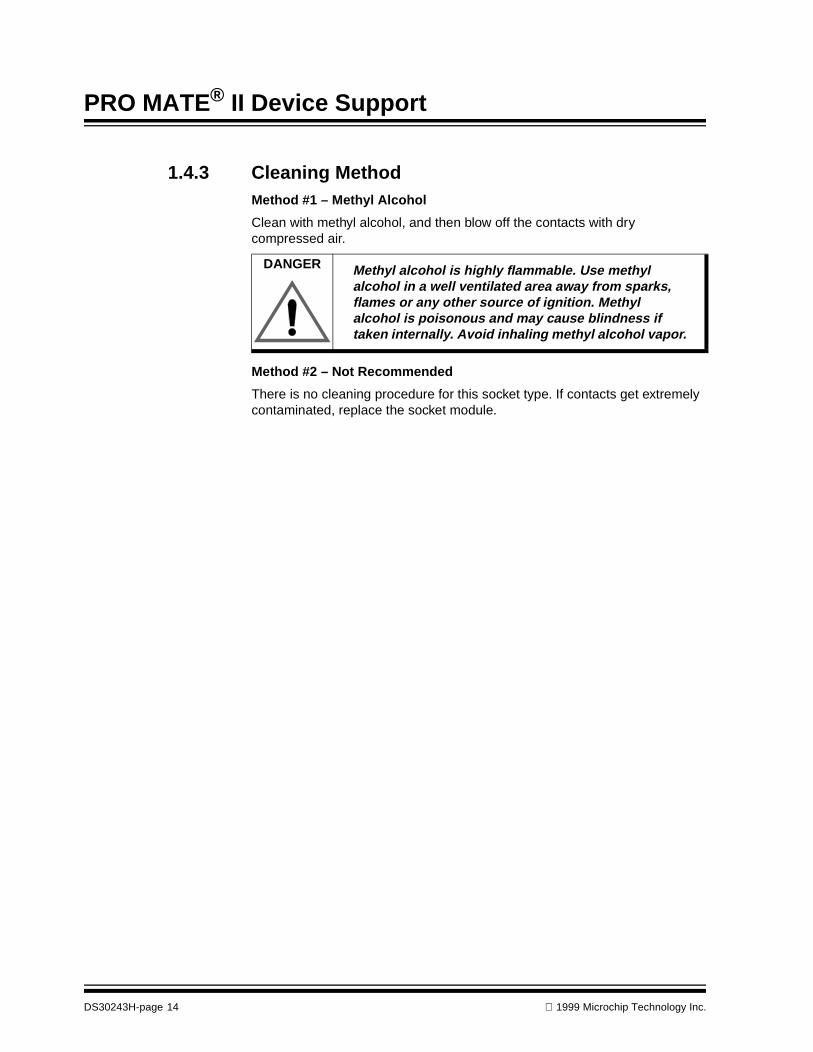
DANGER Methyl alcohol is highly flammable. Use methyl alcohol in a well ventilated area away from sparks, flames or any other source of ignition. Methyl alcohol is poisonous and may cause blindness if taken internally. Avoid inhaling methyl alcohol vapor.
DS30243H-page 14 1999 Microchip Technology Inc.
®
PRO MATE II DEVICE SUPPORTChapter 2. Programming Devices with Calibration
2.1 IntroductionThis chapter deals exclusively with information about programming devices with calibration:
• PIC12C508/508A
• PIC12C509/509A
• PIC12CE518
• PIC12CE519
• PIC12C671
• PIC12C672
• PIC12EC673
• PIC12EC674
• PIC14C000
• PIC16C505
2.2 HighlightsThe topics covered in this chapter are:
• Programmer Dialogs
• Calibration Windows
1999 Microchip Technology Inc. DS30243H-page 15

PRO MATE® II Device Support
2.3 Programmer DialogsPRO MATE II Device Programmer and Configuration Bits dialogs for devices requiring calibration are the same as any other PICmicro device (Figure 2.1and Figure 2.2). Follow the instructions detailing how to program PICmicro devices in the PRO MATE II User’s Guide (DS30028).
Figure 2.1: Device Programmer Dialog – PIC14C000
Figure 2.2: Configuration Bits Dialog – PIC14C000
DS30243H-page 16 1999 Microchip Technology Inc.

Chapter 2. Programming Devices with Calibration
2.4 Calibration WindowsThe calibration data is displayed in a separate window by selecting Window > Calibration Data.
On windowed devices, the calibration data should be read out of the device andstored in a file prior to first use. Once saved, calibration files may be loadedusing File > Import.
Figure 2.3: Calibration Data – PIC14C000
Figure 2.4: Calibration Data – All Other Devices
1999 Microchip Technology Inc. DS30243H-page 17

PRO MATE® II Device Support
NOTES:
DS30243H-page 18 1999 Microchip Technology Inc.

®
PRO MATE II DEVICE SUPPORTChapter 3. Programming KEELOQ® Devices
3.1 IntroductionThis chapter deals exclusively with information about programming KEELOQ devices.
3.2 HighlightsThe topics covered in this chapter are:
• Programming Overview
• Key Generation
• Manufacturer’s Code
• HCS200 Options
• HCS201 Options
• HCS300 Options
• HCS301 Options
• HCS320 Options
• HCS360 Options
• HCS361 Options
• HCS410 Options
• HCS412 Options
• HCS512 Options
3.3 Programming OverviewProgramming of KEELOQ Encoders requires four steps:
1. Select the encoder2. Enter the manufacturer's code3. Select the decoder4. Select the encoder options.
A KEELOQ encoder can be selected as you would any other device supported by PRO MATE II (Figure 3.1).
1999 Microchip Technology Inc. DS30243H-page 19

PRO MATE® II Device Support
Figure 3.1: Device Programmer Dialog – HCS200
The next step is to click on the Program button. The user will then be prompted for two 20-bit custodian keys (Figure 3.2). These are combined to form the manufacturer’s code. The manufacturer’s key is used in key generation as described later in this document.
Figure 3.2: Enter Key Dialog – Custodian Key 1
The appropriate dialog for the selected device will be displayed (Figure 3.3). The user should then select a Decoder. Some of the decoders have multiple key generation methods. If the selected decoder has different key generation options, the user will be prompted to select these options at that time. After this, the user should select the encoder options as desired. These options are described later in this document for each HCS device.
Once all options are selected, programming can begin. Click Program to program the device or Close to exit without programming.
DS30243H-page 20 1999 Microchip Technology Inc.
Chapter 3. Programming KEELOQ® Devices
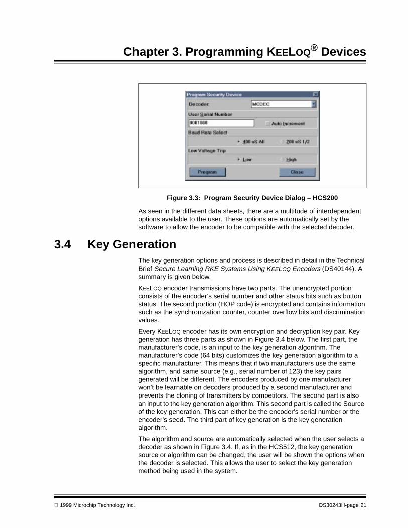
Figure 3.3: Program Security Device Dialog – HCS200
As seen in the different data sheets, there are a multitude of interdependent options available to the user. These options are automatically set by the software to allow the encoder to be compatible with the selected decoder.
3.4 Key GenerationThe key generation options and process is described in detail in the Technical Brief Secure Learning RKE Systems Using KEELOQ Encoders (DS40144). A summary is given below.
KEELOQ encoder transmissions have two parts. The unencrypted portion consists of the encoder’s serial number and other status bits such as button status. The second portion (HOP code) is encrypted and contains information such as the synchronization counter, counter overflow bits and discrimination values.
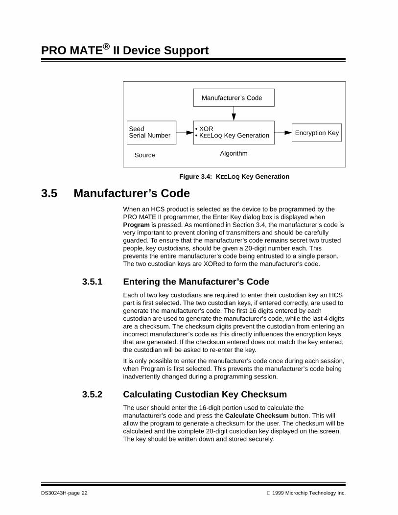
Every KEELOQ encoder has its own encryption and decryption key pair. Key generation has three parts as shown in Figure 3.4 below. The first part, the manufacturer’s code, is an input to the key generation algorithm. The manufacturer’s code (64 bits) customizes the key generation algorithm to a specific manufacturer. This means that if two manufacturers use the same algorithm, and same source (e.g., serial number of 123) the key pairs generated will be different. The encoders produced by one manufacturer won’t be learnable on decoders produced by a second manufacturer and prevents the cloning of transmitters by competitors. The second part is also an input to the key generation algorithm. This second part is called the Source of the key generation. This can either be the encoder’s serial number or the encoder’s seed. The third part of key generation is the key generation algorithm.
The algorithm and source are automatically selected when the user selects a decoder as shown in Figure 3.4. If, as in the HCS512, the key generation source or algorithm can be changed, the user will be shown the options when the decoder is selected. This allows the user to select the key generation method being used in the system.
1999 Microchip Technology Inc. DS30243H-page 21
PRO MATE® II Device Support
Figure 3.4: KEELOQ Key Generation
3.5 Manufacturer’s CodeWhen an HCS product is selected as the device to be programmed by the PRO MATE II programmer, the Enter Key dialog box is displayed when Program is pressed. As mentioned in Section 3.4, the manufacturer’s code is very important to prevent cloning of transmitters and should be carefully guarded. To ensure that the manufacturer’s code remains secret two trusted people, key custodians, should be given a 20-digit number each. This prevents the entire manufacturer’s code being entrusted to a single person. The two custodian keys are XORed to form the manufacturer’s code.
3.5.1 Entering the Manufacturer’s CodeEach of two key custodians are required to enter their custodian key an HCS part is first selected. The two custodian keys, if entered correctly, are used to generate the manufacturer’s code. The first 16 digits entered by each custodian are used to generate the manufacturer’s code, while the last 4 digits are a checksum. The checksum digits prevent the custodian from entering an incorrect manufacturer’s code as this directly influences the encryption keys that are generated. If the checksum entered does not match the key entered, the custodian will be asked to re-enter the key.
It is only possible to enter the manufacturer’s code once during each session, when Program is first selected. This prevents the manufacturer’s code being inadvertently changed during a programming session.
3.5.2 Calculating Custodian Key ChecksumThe user should enter the 16-digit portion used to calculate the manufacturer’s code and press the Calculate Checksum button. This will allow the program to generate a checksum for the user. The checksum will be calculated and the complete 20-digit custodian key displayed on the screen. The key should be written down and stored securely.
Manufacturer’s Code
Seed • XOREncryption KeySerial Number
Source Algorithm
• KEELOQ Key Generation
DS30243H-page 22 1999 Microchip Technology Inc.

Chapter 3. Programming KEELOQ® Devices
3.5.3 Changing the Manufacturer’s CodeIt is possible that a manufacturer would like to have different manufacturer’s codes for different product lines. It is not possible to change the manufacturer’s code during a programming session. This prevents the manufacturer’s code being inadvertently changed during a programming session.
To change the manufacturer’s code, exit PRO MATE II and enter the new manufacturer’s code when the program is restarted.
3.5.4 Key Generation Source and AlgorithmsThe key generation source and algorithms are selected when the user selects a decoder. The source and algorithm selected for each decoder is given in Table 3.5.
Table: 3.5 KEELOQ Decoder Key Generation Methods
Decoder Source Algorithm
Serial Number
Seed Decryption Algorithm
SIMDEC* No key generation. The simple decoder uses the manufacturer’s code
MCDEC* X X
MCSLRN* X X X
HCS512 X X X X
*The MCDEC, MCSLRN and SIMDEC decoders are software decoders. These decoders have been written as a “quick start” to a customer who would like to write a custom decoder. The source code for the decoders and application note describing each of the decoders is available by ordering DS40149 from your local Microchip representative.
1999 Microchip Technology Inc. DS30243H-page 23
PRO MATE® II Device Support
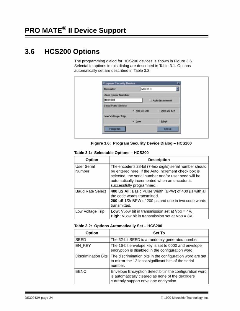
3.6 HCS200 OptionsThe programming dialog for HCS200 devices is shown in Figure 3.6. Selectable options in this dialog are described in Table 3.1. Options automatically set are described in Table 3.2.
Figure 3.6: Program Security Device Dialog – HCS200
Table 3.1: Selectable Options – HCS200
Option Description
User Serial Number
The encoder’s 28-bit (7-hex digits) serial number should be entered here. If the Auto Increment check box is selected, the serial number and/or user seed will be automatically incremented when an encoder is successfully programmed.
Baud Rate Select 400 uS All: Basic Pulse Width (BPW) of 400 µs with all the code words transmitted.200 uS 1/2: BPW of 200 µs and one in two code words transmitted.
Low Voltage Trip Low: VLOW bit in transmission set at VDD = 4V.High: VLOW bit in transmission set at VDD = 8V.
Table 3.2: Options Automatically Set – HCS200
Option Set To
SEED The 32-bit SEED is a randomly generated number.
EN_KEY The 16-bit envelope key is set to 0000 and envelope encryption is disabled in the configuration word.
Discrimination Bits The discrimination bits in the configuration word are set to mirror the 12 least significant bits of the serial number.
EENC Envelope Encryption Select bit in the configuration word is automatically cleared as none of the decoders currently support envelope encryption.
DS30243H-page 24 1999 Microchip Technology Inc.
Chapter 3. Programming KEELOQ® Devices
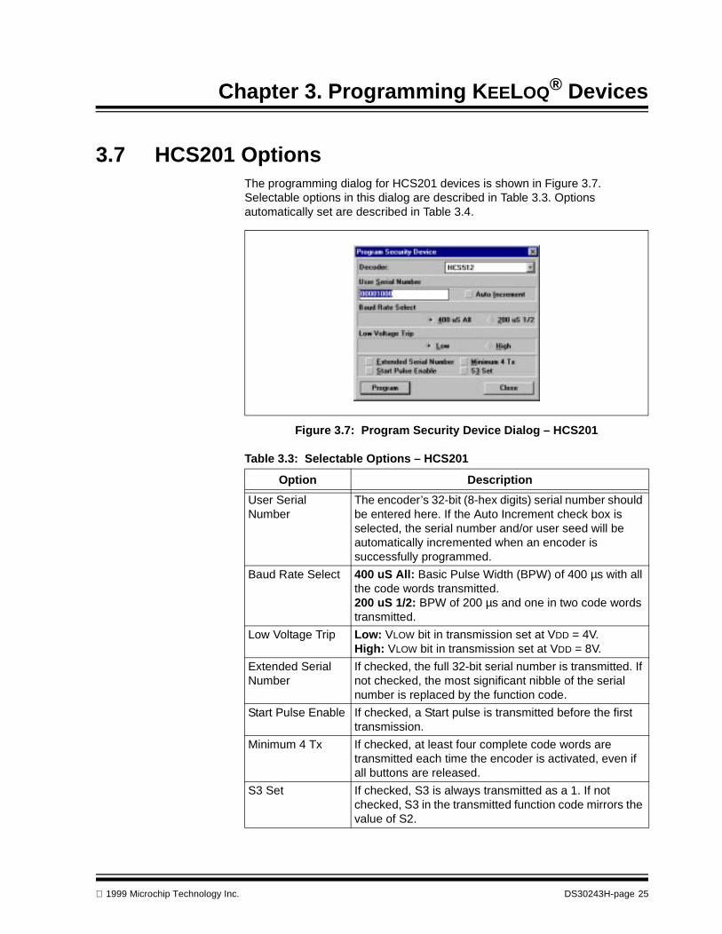
3.7 HCS201 OptionsThe programming dialog for HCS201 devices is shown in Figure 3.7. Selectable options in this dialog are described in Table 3.3. Options automatically set are described in Table 3.4.
Figure 3.7: Program Security Device Dialog – HCS201
Table 3.3: Selectable Options – HCS201
Option Description
User Serial Number
The encoder’s 32-bit (8-hex digits) serial number should be entered here. If the Auto Increment check box is selected, the serial number and/or user seed will be automatically incremented when an encoder is successfully programmed.
Baud Rate Select 400 uS All: Basic Pulse Width (BPW) of 400 µs with all the code words transmitted.200 uS 1/2: BPW of 200 µs and one in two code words transmitted.
Low Voltage Trip Low: VLOW bit in transmission set at VDD = 4V.High: VLOW bit in transmission set at VDD = 8V.
Extended Serial Number
If checked, the full 32-bit serial number is transmitted. If not checked, the most significant nibble of the serial number is replaced by the function code.
Start Pulse Enable If checked, a Start pulse is transmitted before the first transmission.
Minimum 4 Tx If checked, at least four complete code words are transmitted each time the encoder is activated, even if all buttons are released.
S3 Set If checked, S3 is always transmitted as a 1. If not checked, S3 in the transmitted function code mirrors the value of S2.
1999 Microchip Technology Inc. DS30243H-page 25
PRO MATE® II Device Support
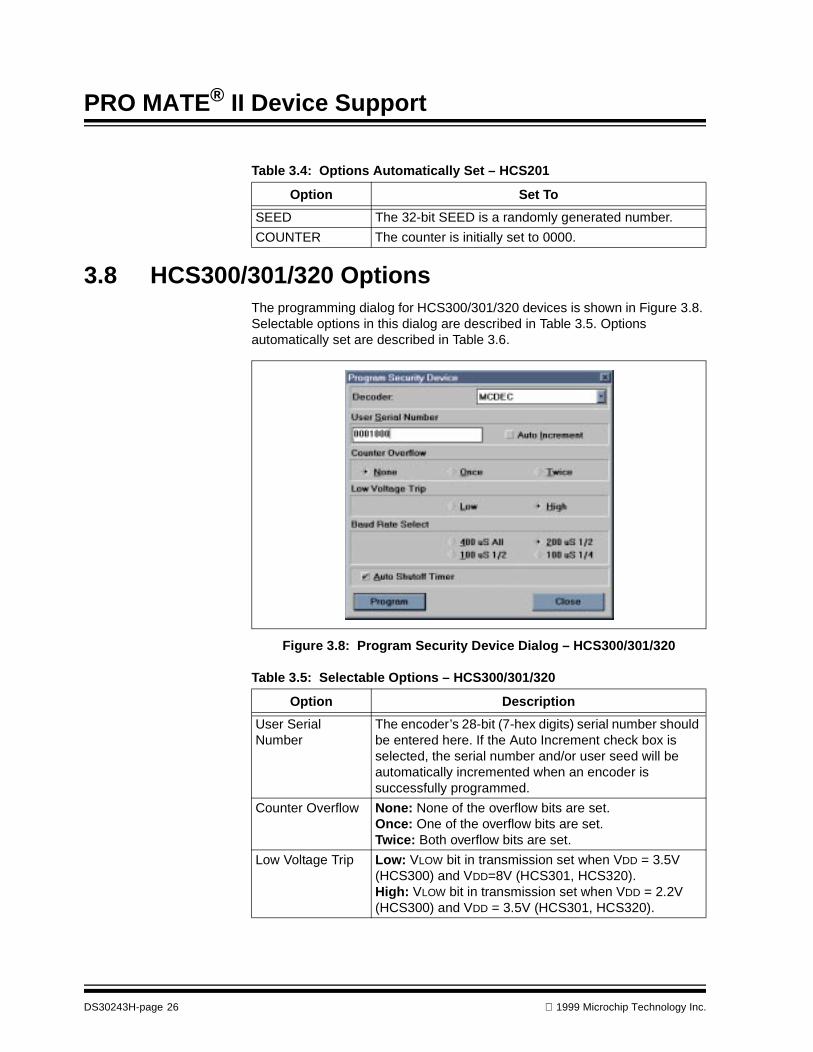
3.8 HCS300/301/320 OptionsThe programming dialog for HCS300/301/320 devices is shown in Figure 3.8. Selectable options in this dialog are described in Table 3.5. Options automatically set are described in Table 3.6.
Figure 3.8: Program Security Device Dialog – HCS300/301/320
Table 3.4: Options Automatically Set – HCS201
Option Set To
SEED The 32-bit SEED is a randomly generated number.
COUNTER The counter is initially set to 0000.
Table 3.5: Selectable Options – HCS300/301/320
Option Description
User Serial Number
The encoder’s 28-bit (7-hex digits) serial number should be entered here. If the Auto Increment check box is selected, the serial number and/or user seed will be automatically incremented when an encoder is successfully programmed.
Counter Overflow None: None of the overflow bits are set.Once: One of the overflow bits are set.Twice: Both overflow bits are set.
Low Voltage Trip Low: VLOW bit in transmission set when VDD = 3.5V (HCS300) and VDD=8V (HCS301, HCS320).High: VLOW bit in transmission set when VDD = 2.2V (HCS300) and VDD = 3.5V (HCS301, HCS320).
DS30243H-page 26 1999 Microchip Technology Inc.

Chapter 3. Programming KEELOQ® Devices
Baud Rate Select 400 uS All: Basic Pulse Width (BPW) of 400 µs with all the code words transmitted.200 uS 1/2: BPW of 200 µs and one in two code words transmitted.100 uS 1/2: BPW of 100 µs and one in two code words transmitted.100 uS 1/4: BPW of 100 µs and one in four code words transmitted.
Auto Shutoff Timer The automatic shutoff can be enabled preventing the battery of a transmitter going flat if the transmitter is accidentally pressed in a pocket or purse.
Table 3.6: Options Automatically Set – HCS300/301/320
Option Set To
SEED* The 32-bit SEED is a randomly generated number.
EN_KEY The 16-bit envelope key is set to 0000 and envelope encryption is disabled in the configuration word.
Discrimination Bits The discrimination bits in the configuration word are set to mirror the 12 least significant bits of the serial number.
EENC Envelope Encryption Select bit in the configuration word is automatically cleared as none of the decoders currently support envelope encryption.
* Not available on the HCS320
Table 3.5: Selectable Options – HCS300/301/320 (Continued)
Option Description
1999 Microchip Technology Inc. DS30243H-page 27

PRO MATE® II Device Support
3.9 HCS360 OptionsThe programming dialog for HCS360 devices is shown in Figure 3.9. Selectable options in this dialog are described in Table 3.7 and Table 3.8. Options automatically set are described in Table 3.9.
Figure 3.9: Program Security Device Dialog – HCS360
Table 3.7: Selectable Options – HCS360
Option Description
User Serial Number
The encoder’s 32-bit (8-hex digits) serial number should be entered here. If the Auto Increment check box is selected, the serial number and/or user seed will be automatically incremented when an encoder is successfully programmed.
Modulation Format If this is enabled, the transmitted string is Manchester modulated, if the option is not enabled Pulse Width Modulation (PWM) is used.
Baud Rate Select See Table 3.8.
Code Word Blanking
Every alternate code word can be blanked out, thereby, increasing the amount of power transmitted per transmission if needed.
Delayed Mode If this is enabled the encoder will transmit a delayed transmission after a time, see the HCS360 Data Sheet (DS40152) for more details.
DS30243H-page 28 1999 Microchip Technology Inc.
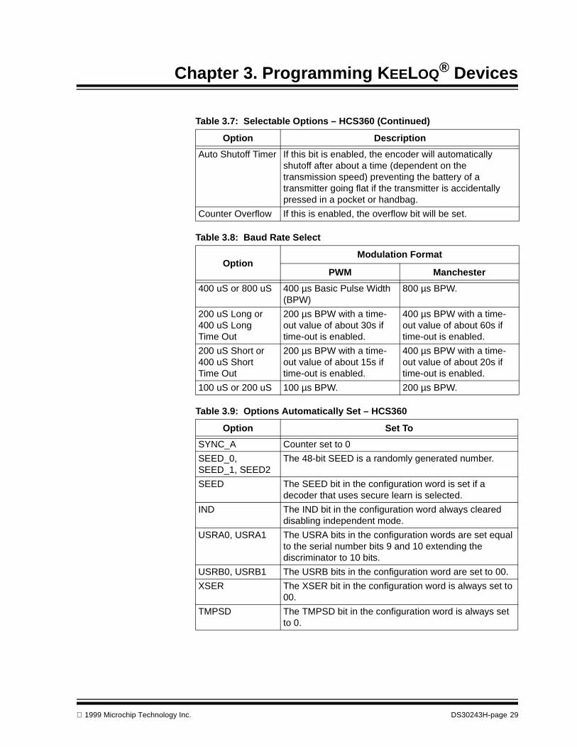
Chapter 3. Programming KEELOQ® Devices
Auto Shutoff Timer If this bit is enabled, the encoder will automatically shutoff after about a time (dependent on the transmission speed) preventing the battery of a transmitter going flat if the transmitter is accidentally pressed in a pocket or handbag.
Counter Overflow If this is enabled, the overflow bit will be set.
Table 3.8: Baud Rate Select
OptionModulation Format
PWM Manchester
400 uS or 800 uS 400 µs Basic Pulse Width (BPW)
800 µs BPW.
200 uS Long or 400 uS Long Time Out
200 µs BPW with a time-out value of about 30s if time-out is enabled.
400 µs BPW with a time-out value of about 60s if time-out is enabled.
200 uS Short or 400 uS Short Time Out
200 µs BPW with a time-out value of about 15s if time-out is enabled.
400 µs BPW with a time-out value of about 20s if time-out is enabled.
100 uS or 200 uS 100 µs BPW. 200 µs BPW.
Table 3.9: Options Automatically Set – HCS360
Option Set To
SYNC_A Counter set to 0
SEED_0, SEED_1, SEED2
The 48-bit SEED is a randomly generated number.
SEED The SEED bit in the configuration word is set if a decoder that uses secure learn is selected.
IND The IND bit in the configuration word always cleared disabling independent mode.
USRA0, USRA1 The USRA bits in the configuration words are set equal to the serial number bits 9 and 10 extending the discriminator to 10 bits.
USRB0, USRB1 The USRB bits in the configuration word are set to 00.
XSER The XSER bit in the configuration word is always set to 00.
TMPSD The TMPSD bit in the configuration word is always set to 0.
Table 3.7: Selectable Options – HCS360 (Continued)
Option Description
1999 Microchip Technology Inc. DS30243H-page 29
PRO MATE® II Device Support
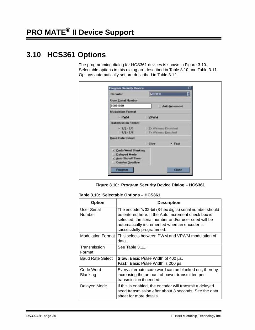
3.10 HCS361 OptionsThe programming dialog for HCS361 devices is shown in Figure 3.10. Selectable options in this dialog are described in Table 3.10 and Table 3.11. Options automatically set are described in Table 3.12.
Figure 3.10: Program Security Device Dialog – HCS361
Table 3.10: Selectable Options – HCS361
Option Description
User Serial Number
The encoder’s 32-bit (8-hex digits) serial number should be entered here. If the Auto Increment check box is selected, the serial number and/or user seed will be automatically incremented when an encoder is successfully programmed.
Modulation Format This selects between PWM and VPWM modulation of data.
Transmission Format
See Table 3.11.
Baud Rate Select Slow: Basic Pulse Width of 400 µs.Fast: Basic Pulse Width is 200 µs.
Code Word Blanking
Every alternate code word can be blanked out, thereby, increasing the amount of power transmitted per transmission if needed.
Delayed Mode If this is enabled, the encoder will transmit a delayed seed transmission after about 3 seconds. See the data sheet for more details.
DS30243H-page 30 1999 Microchip Technology Inc.

Chapter 3. Programming KEELOQ® Devices
Auto Shutoff Timer If this bit is enabled, the encoder will automatically shutoff after a time (dependent on the transmission speed) preventing the battery of a transmitter going flat if the transmitter is accidentally pressed in a pocket or handbag.
Counter Overflow If this is enabled, the overflow bit will be set.
Table 3.11: Transmission Format
OptionModulation Format
PWM VPWM
1/3 – 2/3 or Tx Wakeup Disabled
A to PWM duty cycle
is used.
No wakeup pulse train transmitted on first transmission.
1/6 – 2/6 or Tx Wakeup Enabled A to PWM duty cycle
is used.
A wakeup pulse train is transmitted before the first code word.
Table 3.12: Options Automatically Set – HCS361
Option Set To
SYNC_A Counter set to 0
SEED_0, SEED_1, SEED2
The 48 bit SEED is a randomly generated number.
SPM The SPM bit in the configuration word is always set to 1.
SEED The SEED bit in the configuration word is set if a decoder that uses secure learn is selected.
IND The IND bit in the configuration word always cleared disabling independent mode.
USRA0, USRA1 The USRA bits in the configuration words are set equal to the serial number bits 9 and 10 extending the discriminator to 10 bits.
USRB0, USRB1 The USRB bits in the configuration word are set to 00.
XSER The XSER bit in the configuration word is always set to 00.
TMPSD The TMPSD bit in the configuration word is always set to 0.
Table 3.10: Selectable Options – HCS361 (Continued)
Option Description
13---
23---
16---
26---
1999 Microchip Technology Inc. DS30243H-page 31

PRO MATE® II Device Support
3.11 HCS410 OptionsThe programming dialog for HCS410 devices is shown in Figure 3.11. Selectable options in this dialog are described in Table 3.13 and Table 3.14. Options automatically set are described in Table 3.15.
Figure 3.11: Program Security Device Dialog – HCS410
Table 3.13: Selectable Options – HCS410
Option Description
User Serial Number
The encoder’s 32-bit (8-hex digits) serial number should be entered here. If the Auto Increment check box is selected, the serial number and/or user seed will be automatically incremented when an encoder is successfully programmed.
Seed/IFF2 No Seed: No seed is transmitted even if the seed button combination is pressed. Only 1 key is available for IFF challenge – response.Limited Seed: Seed transmissions allowed for a maxi-mum of 255 transmissions, only 1 key available for IFF challenge – response.Seed: Seed transmissions always allowed, only 1 key available for IFF challenge –response.2 Key IFF: No seed transmissions are allowed, 2 keys available for IFF challenge – response.
DS30243H-page 32 1999 Microchip Technology Inc.
Chapter 3. Programming KEELOQ® Devices
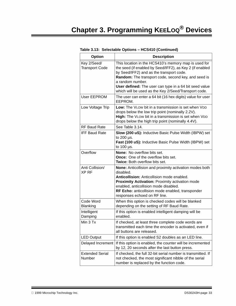
Key 2/Seed/Transport Code
This location in the HCS410’s memory map is used for the seed (if enabled by Seed/IFF2), as Key 2 (if enabled by Seed/IFF2) and as the transport code.Random: The transport code, second key, and seed is a random number.User defined: The user can type in a 64 bit seed value which will be used as the Key 2/Seed/Transport code.
User EEPROM The user can enter a 64 bit (16 hex digits) value for user EEPROM.
Low Voltage Trip Low: The VLOW bit in a transmission is set when VDD drops below the low trip point (nominally 2.2V).High: The VLOW bit in a transmission is set when VDD drops below the high trip point (nominally 4.4V).
RF Baud Rate See Table 3.14.
IFF Baud Rate Slow (200 uS): Inductive Basic Pulse Width (IBPW) set to 200 µs.Fast (100 uS): Inductive Basic Pulse Width (IBPW) set to 100 µs.
Overflow None: No overflow bits set.Once: One of the overflow bits set.Twice: Both overflow bits set.
Anti Collision/XP RF
None: Anticollision and proximity activation modes both disabled.Anticollision: Anticollision mode enabled.Proximity Activation: Proximity activation mode enabled, anticollision mode disabled.RF Echo: anticollision mode enabled, transponder responses echoed on RF line.
Code Word Blanking
When this option is checked codes will be blanked depending on the setting of RF Baud Rate.
Intelligent Damping
If this option is enabled intelligent damping will be enabled.
Min 3 Tx If checked, at least three complete code words are transmitted each time the encoder is activated, even if all buttons are released.
LED Output If this option is enabled S2 doubles as an LED line.
Delayed Increment If this option is enabled, the counter will be incremented by 12, 20 seconds after the last button press.
Extended Serial Number
If checked, the full 32-bit serial number is transmitted. If not checked, the most significant nibble of the serial number is replaced by the function code.
Table 3.13: Selectable Options – HCS410 (Continued)
Option Description
1999 Microchip Technology Inc. DS30243H-page 33

PRO MATE® II Device Support
Table 3.14: RF Baud Rate
OptionBasic Pulse Width (BPW) Code Words
Transmitted*PWM Manchester
00 (slow) 400 µs 800 µs All
01 200 µs 400 µs 1 of 2
10 100 µs 200 µs 1 of 2
11 (fast) 100 µs 200 µs 1 of 4
* If enabled by code word blanking
Table 3.15: Options Automatically Set – HCS410
Option Set To
Modulation Format The modulation format is set to PWM.
Discrimination Bits The discrimination bits in the configuration word are set to mirror the 10 least significant bits of the serial number
Counter The counter is set to 0.
DS30243H-page 34 1999 Microchip Technology Inc.

Chapter 3. Programming KEELOQ® Devices
3.12 HCS412 OptionsThe programming dialog for HCS412 devices is shown in Figure 3.12. Selectable options in this dialog are described in Table 3.16. Options automatically set are described in Table 3.18.
Figure 3.12: Program Security Device Dialog – HCS412
Table 3.16: Selectable Options – HCS412
Option Description
User Serial Number
The encoder’s 32-bit (8-hex digits) serial number should be entered here. If the Auto Increment check box is selected, the serial number and/or user seed will be automatically incremented when an encoder is successfully programmed.
Seed/IFF2 No Seed: No seed is transmitted even if the seed button combination is pressed. Only 1 key is available for IFF challenge – response.Limited Seed: Seed transmissions allowed for a maxi-mum of 128 transmissions, only 1 key available for IFF challenge – response.Seed: Seed transmissions always allowed, only 1 key available for IFF challenge – response.2 Key IFF: No seed transmissions are allowed, 2 keys available for IFF challenge – response.
1999 Microchip Technology Inc. DS30243H-page 35
PRO MATE® II Device Support
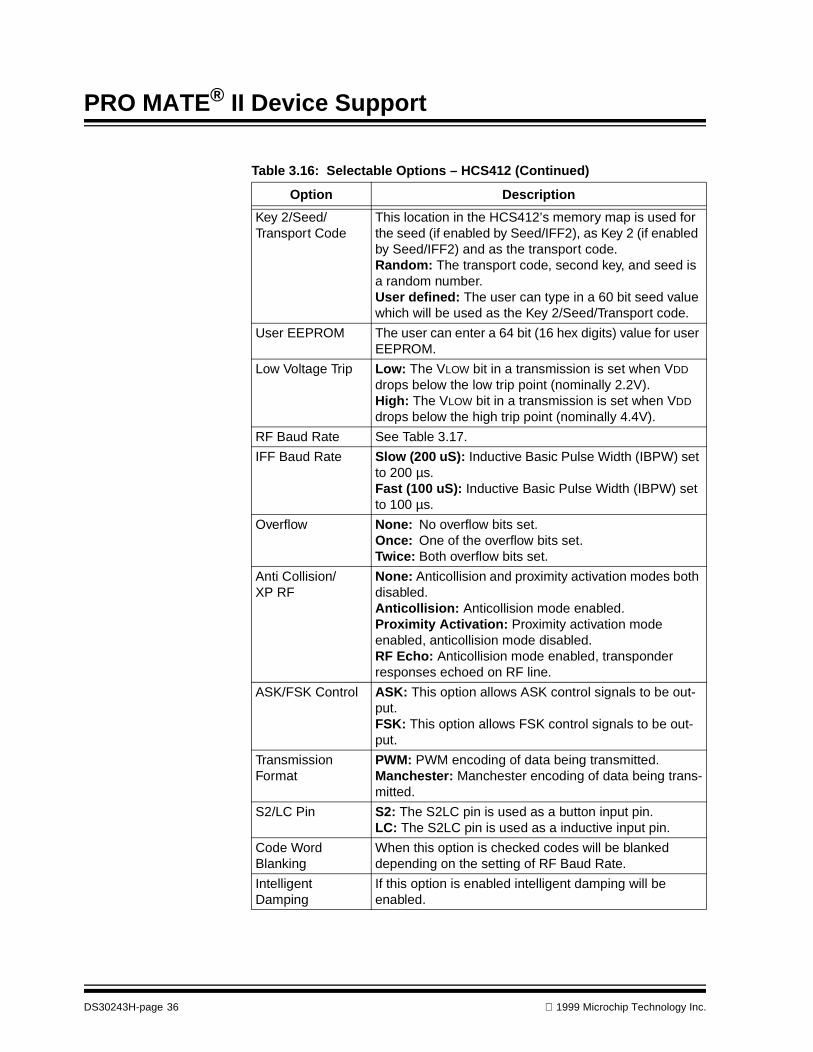
Key 2/Seed/Transport Code
This location in the HCS412’s memory map is used for the seed (if enabled by Seed/IFF2), as Key 2 (if enabled by Seed/IFF2) and as the transport code.Random: The transport code, second key, and seed is a random number.User defined: The user can type in a 60 bit seed value which will be used as the Key 2/Seed/Transport code.
User EEPROM The user can enter a 64 bit (16 hex digits) value for user EEPROM.
Low Voltage Trip Low: The VLOW bit in a transmission is set when VDD drops below the low trip point (nominally 2.2V).High: The VLOW bit in a transmission is set when VDD drops below the high trip point (nominally 4.4V).
RF Baud Rate See Table 3.17.
IFF Baud Rate Slow (200 uS): Inductive Basic Pulse Width (IBPW) set to 200 µs.Fast (100 uS): Inductive Basic Pulse Width (IBPW) set to 100 µs.
Overflow None: No overflow bits set.Once: One of the overflow bits set.Twice: Both overflow bits set.
Anti Collision/XP RF
None: Anticollision and proximity activation modes both disabled.Anticollision: Anticollision mode enabled.Proximity Activation: Proximity activation mode enabled, anticollision mode disabled.RF Echo: Anticollision mode enabled, transponder responses echoed on RF line.
ASK/FSK Control ASK: This option allows ASK control signals to be out-put.FSK: This option allows FSK control signals to be out-put.
Transmission Format
PWM: PWM encoding of data being transmitted.Manchester: Manchester encoding of data being trans-mitted.
S2/LC Pin S2: The S2LC pin is used as a button input pin.LC: The S2LC pin is used as a inductive input pin.
Code Word Blanking
When this option is checked codes will be blanked depending on the setting of RF Baud Rate.
Intelligent Damping
If this option is enabled intelligent damping will be enabled.
Table 3.16: Selectable Options – HCS412 (Continued)
Option Description
DS30243H-page 36 1999 Microchip Technology Inc.
Chapter 3. Programming KEELOQ® Devices
Min 4 Tx If checked, at least four complete code words are trans-mitted each time the encoder is activated, even if all buttons are released.
Long Preamble If this option is enabled, a long preamble is transmitted before the first code word.
Delayed Increment If this option is enabled, the counter will be incremented by 12, 20 seconds after the last button press.
Extended Serial Number
If checked, the full 32-bit serial number is transmitted. If not checked, the most significant nibble of the serial number is replaced by the function code.
Table 3.17: RF Baud Rate
OptionBasic Pulse Width (BPW) Code Words
Transmitted*PWM Manchester
00 (slow) 400 µs 800 µs All
01 200 µs 400 µs 1 of 2
10 100 µs 200 µs 1 of 2
11 (fast) 100 µs 200 µs 1 of 4
* If enabled by code word blanking
Table 3.18: Options Automatically Set – HCS412
Option Set To
RF Enable This option is disabled.
Demodulator Mode
This option is disabled.
Discrimination Bits The discrimination bits in the configuration word are set to mirror the 10 least significant bits of the serial number
Counter The counter is set to 0.
Table 3.16: Selectable Options – HCS412 (Continued)
Option Description
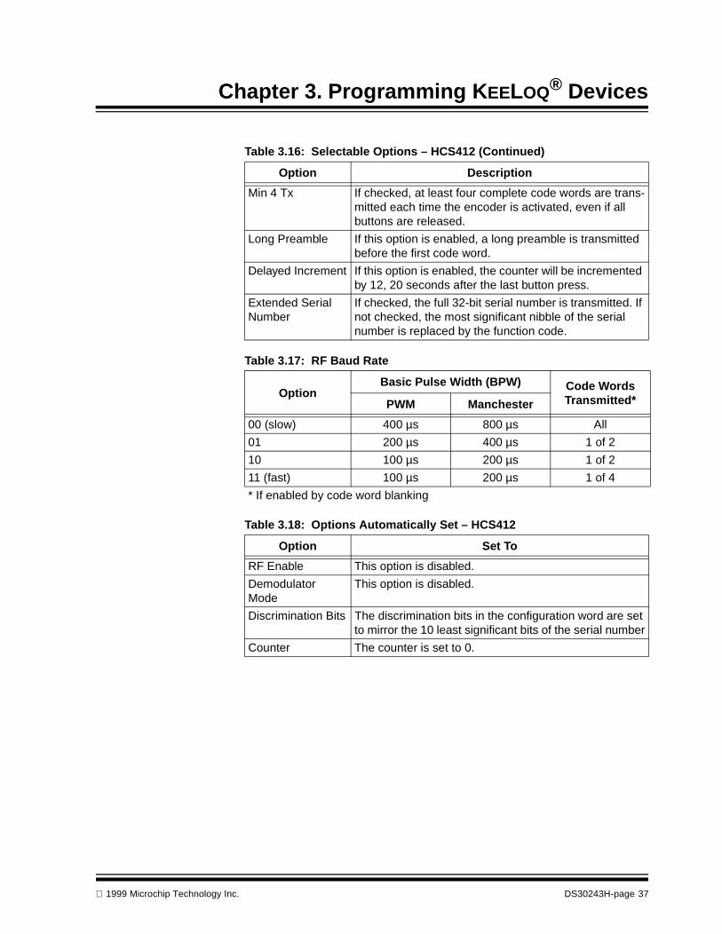
1999 Microchip Technology Inc. DS30243H-page 37
PRO MATE® II Device Support
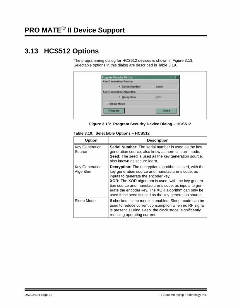
3.13 HCS512 OptionsThe programming dialog for HCS512 devices is shown in Figure 3.13. Selectable options in this dialog are described in Table 3.19.
Figure 3.13: Program Security Device Dialog – HCS512
Table 3.19: Selectable Options – HCS512
Option Description
Key Generation Source
Serial Number: The serial number is used as the key generation source, also know as normal learn mode.Seed: The seed is used as the key generation source, also known as secure learn.
Key Generation Algorithm
Decryption: The decryption algorithm is used, with the key generation source and manufacturer’s code, as inputs to generate the encoder key.XOR: The XOR algorithm is used, with the key genera-tion source and manufacturer’s code, as inputs to gen-erate the encoder key. The XOR algorithm can only be used if the seed is used as the key generation source.
Sleep Mode If checked, sleep mode is enabled. Sleep mode can be used to reduce current consumption when no RF signal is present. During sleep, the clock stops, significantly reducing operating current.
DS30243H-page 38 1999 Microchip Technology Inc.
®
PRO MATE II DEVICE SUPPORTChapter 4. Programming Memory Devices
4.1 IntroductionThis chapter deals exclusively with information about programming memory devices.
4.2 HighlightsThe topic covered in this chapter is:
• Programming Overview – Memory Devices
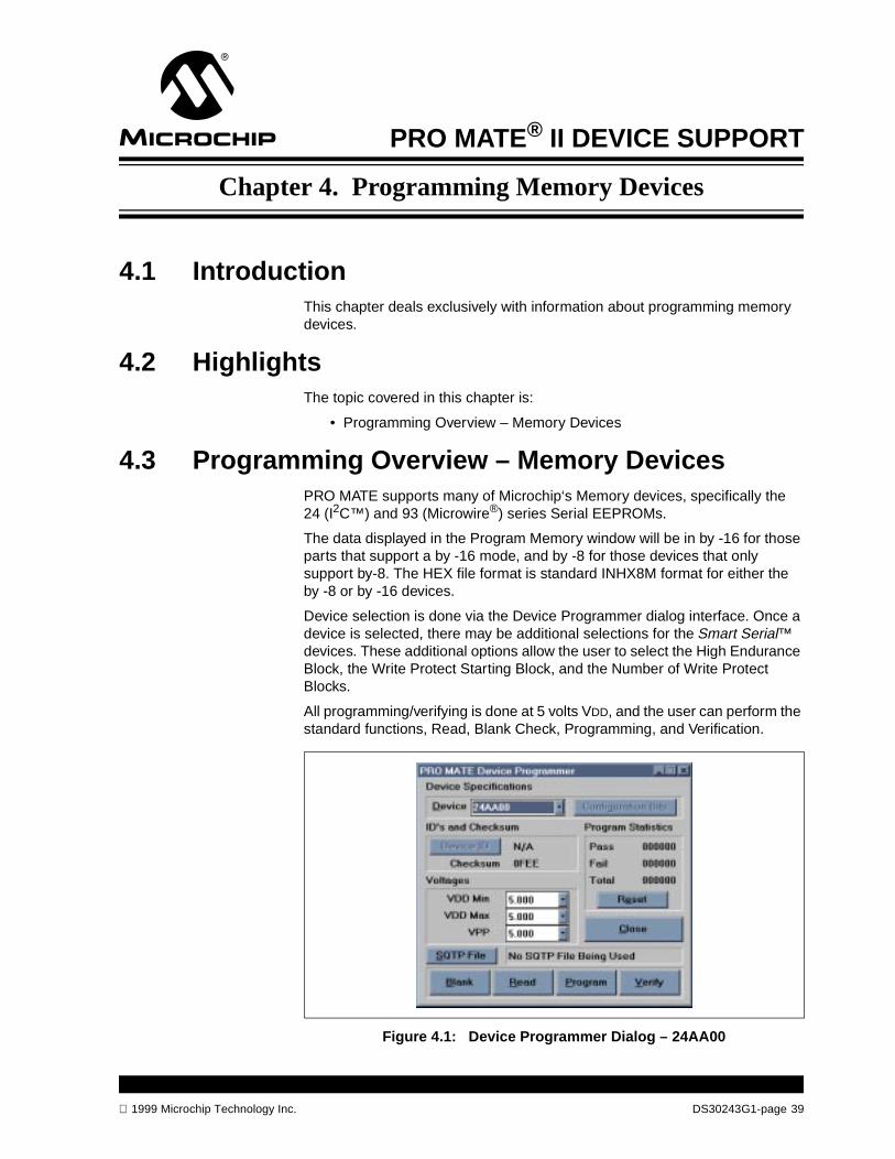
4.3 Programming Overview – Memory DevicesPRO MATE supports many of Microchip‘s Memory devices, specifically the 24 (I2C™) and 93 (Microwire®) series Serial EEPROMs.
The data displayed in the Program Memory window will be in by -16 for those parts that support a by -16 mode, and by -8 for those devices that only support by-8. The HEX file format is standard INHX8M format for either the by -8 or by -16 devices.
Device selection is done via the Device Programmer dialog interface. Once a device is selected, there may be additional selections for the Smart Serial™ devices. These additional options allow the user to select the High Endurance Block, the Write Protect Starting Block, and the Number of Write Protect Blocks.
All programming/verifying is done at 5 volts VDD, and the user can perform the standard functions, Read, Blank Check, Programming, and Verification.
Figure 4.1: Device Programmer Dialog – 24AA00
1999 Microchip Technology Inc. DS30243G1-page 39
PRO MATE® II Device Support
NOTES:
DS30243G1-page 40 1999 Microchip Technology Inc.
PRO MATE® II DEVICE SUPPORT
Index
Numerics24 Series Serial EEPROMs ....................................3993 Series Serial EEPROMs ....................................39
CCalibration Data ..........................................................17Calibration Devices, Programming ......................15Calibration Files ..........................................................17Calibration Window ...................................................17Customer Support .......................................................7
DDevice Package Acronyms .......................................9Document Conventions .............................................2
EEncoders, Programming ..........................................19
HHCS200 Options ........................................................24HCS201 Options ........................................................25HCS300/301/320 Options .......................................26HCS360 Options ........................................................28HCS361 Options ........................................................30HCS410 Options ........................................................32HCS412 Options ........................................................35HCS512 Options ........................................................38
IInternet Address ...........................................................4
KKEELOQ Encoders, Programming ......................19Key Generation ...........................................................21
MManufacturer’s Code ................................................22Memory Devices, Programming ............................39Microchip Internet Web Site .....................................4
PPackage Types .............................................................9PIC12CXXX Programming .....................................15PIC14C000 Programming .......................................15PIC16C505 Programming .......................................15
Programming Devices with Calibration .............. 15Programming Memory Devices ............................ 39
SSecure Data Products, Programming ................. 19Serial EEPROMs ....................................................... 39Socket Cleaning Methods ...................................... 14Socket Life Expectancy ........................................... 13Socket Modules ........................................................... 9Supported Devices ................................................... 10
WWWW Address ............................................................. 4
1999 Microchip Technology Inc. DS30243G1-page 41
PRO MATE® II Device Support
NOTES:
DS30243G1-page 42 1999 Microchip Technology Inc.

NOTES:
1999 Microchip Technology Inc. DS30243G1-page 43

Information contained in this publication regarding device applications and the like is intended for suggestion only and may be superseded by updates. No representation or warranty is given and no liability is assumedby Microchip Technology Incorporated with respect to the accuracy or use of such information, or infringement of patents or other intellectual property rights arising from such use or otherwise. Use of Microchip’s productsas critical components in life support systems is not authorized except with express written approval by Microchip. No licenses are conveyed, implicitly or otherwise, under any intellectual property rights. The Microchiplogo and name are registered trademarks of Microchip Technology Inc. in the U.S.A. and other countries. All rights reserved. All other trademarks mentioned herein are the property of their respective companies.
1999 Microchip Technology Inc.
All rights reserved. © 1999 Microchip Technology Incorporated. Printed in the USA. 11/99 Printed on recycled paper.
AMERICASCorporate OfficeMicrochip Technology Inc.2355 West Chandler Blvd.Chandler, AZ 85224-6199Tel: 480-786-7200 Fax: 480-786-7277Technical Support: 480-786-7627Web Address: http://www.microchip.com
AtlantaMicrochip Technology Inc.500 Sugar Mill Road, Suite 200BAtlanta, GA 30350Tel: 770-640-0034 Fax: 770-640-0307BostonMicrochip Technology Inc.5 Mount Royal AvenueMarlborough, MA 01752Tel: 508-480-9990 Fax: 508-480-8575ChicagoMicrochip Technology Inc.333 Pierce Road, Suite 180Itasca, IL 60143Tel: 630-285-0071 Fax: 630-285-0075DallasMicrochip Technology Inc.4570 Westgrove Drive, Suite 160Addison, TX 75248Tel: 972-818-7423 Fax: 972-818-2924DaytonMicrochip Technology Inc.Two Prestige Place, Suite 150Miamisburg, OH 45342Tel: 937-291-1654 Fax: 937-291-9175DetroitMicrochip Technology Inc.Tri-Atria Office Building 32255 Northwestern Highway, Suite 190Farmington Hills, MI 48334Tel: 248-538-2250 Fax: 248-538-2260Los AngelesMicrochip Technology Inc.18201 Von Karman, Suite 1090Irvine, CA 92612Tel: 949-263-1888 Fax: 949-263-1338New YorkMicrochip Technology Inc.150 Motor Parkway, Suite 202Hauppauge, NY 11788Tel: 631-273-5305 Fax: 631-273-5335San JoseMicrochip Technology Inc.2107 North First Street, Suite 590San Jose, CA 95131Tel: 408-436-7950 Fax: 408-436-7955
AMERICAS (continued)TorontoMicrochip Technology Inc.5925 Airport Road, Suite 200Mississauga, Ontario L4V 1W1, Canada Tel: 905-405-6279 Fax: 905-405-6253
ASIA/PACIFICHong KongMicrochip Asia PacificUnit 2101, Tower 2Metroplaza223 Hing Fong RoadKwai Fong, N.T., Hong KongTel: 852-2-401-1200 Fax: 852-2-401-3431BeijingMicrochip Technology, Beijing Unit 915, 6 Chaoyangmen Bei Dajie Dong Erhuan Road, Dongcheng District New China Hong Kong Manhattan BuildingBeijing 100027 PRC Tel: 86-10-85282100 Fax: 86-10-85282104IndiaMicrochip Technology Inc.India Liaison OfficeNo. 6, Legacy, Convent RoadBangalore 560 025, IndiaTel: 91-80-229-0061 Fax: 91-80-229-0062JapanMicrochip Technology Intl. Inc.Benex S-1 6F3-18-20, ShinyokohamaKohoku-Ku, Yokohama-shiKanagawa 222-0033 JapanTel: 81-45-471- 6166 Fax: 81-45-471-6122KoreaMicrochip Technology Korea168-1, Youngbo Bldg. 3 FloorSamsung-Dong, Kangnam-KuSeoul, KoreaTel: 82-2-554-7200 Fax: 82-2-558-5934ShanghaiMicrochip Technology RM 406 Shanghai Golden Bridge Bldg.2077 Yan’an Road West, Hong Qiao DistrictShanghai, PRC 200335Tel: 86-21-6275-5700 Fax: 86 21-6275-5060
ASIA/PACIFIC (continued)SingaporeMicrochip Technology Singapore Pte Ltd.200 Middle Road#07-02 Prime CentreSingapore 188980Tel: 65-334-8870 Fax: 65-334-8850Taiwan, R.O.CMicrochip Technology Taiwan10F-1C 207Tung Hua North RoadTaipei, Taiwan, ROCTel: 886-2-2717-7175 Fax: 886-2-2545-0139
EUROPEUnited KingdomArizona Microchip Technology Ltd.505 Eskdale RoadWinnersh TriangleWokingham Berkshire, England RG41 5TUTel: 44 118 921 5858 Fax: 44-118 921-5835DenmarkMicrochip Technology Denmark ApSRegus Business CentreLautrup hoj 1-3Ballerup DK-2750 DenmarkTel: 45 4420 9895 Fax: 45 4420 9910FranceArizona Microchip Technology SARLParc d’Activite du Moulin de Massy43 Rue du Saule TrapuBatiment A - ler Etage91300 Massy, FranceTel: 33-1-69-53-63-20 Fax: 33-1-69-30-90-79GermanyArizona Microchip Technology GmbHGustav-Heinemann-Ring 125D-81739 München, GermanyTel: 49-89-627-144 0 Fax: 49-89-627-144-44ItalyArizona Microchip Technology SRLCentro Direzionale Colleoni Palazzo Taurus 1 V. Le Colleoni 120041 Agrate BrianzaMilan, Italy Tel: 39-039-65791-1 Fax: 39-039-6899883
11/15/99
WORLDWIDE SALES AND SERVICE
Microchip received QS-9000 quality system certification for its worldwide headquarters, design and wafer fabrication facilities in Chandler and Tempe, Arizona in July 1999. The Company’s quality system processes and procedures are QS-9000 compliant for its PICmicro® 8-bit MCUs, KEELOQ® code hopping devices, Serial EEPROMs and microperipheral products. In addition, Microchip’s quality system for the design and manufacture of development systems is ISO 9001 certified.