Print), ISSN (Online) UDC/UDK CIRCULAR INTERPOLATION AND ...
6
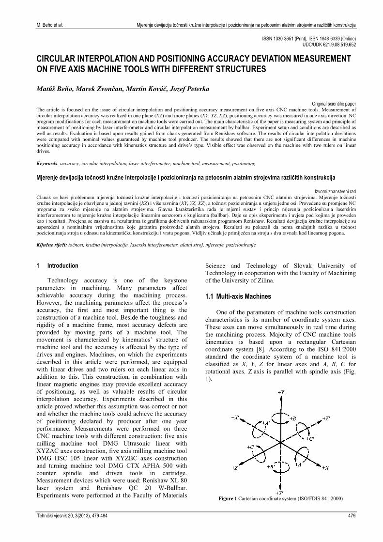
M. Beňo et al. Mjerenje devijacija točnosti kružne interpolacije i pozicioniranja na petoosnim alatnim strojevima različitih konstrukcija ISSN 1330-3651 (Print), ISSN 1848-6339 (Online) UDC/UDK 621.9.08:519.652 CIRCULAR INTERPOLATION AND POSITIONING ACCURACY DEVIATION MEASUREMENT ON FIVE AXIS MACHINE TOOLS WITH DIFFERENT STRUCTURES Matúš Beňo, Marek Zvončan, Martin Kováč, Jozef Peterka Original scientific paper The article is focused on the issue of circular interpolation and positioning accuracy measurement on five axis CNC machine tools. Measurement of circular interpolation accuracy was realized in one plane (XZ) and more planes (XY, YZ, XZ), positioning accuracy was measured in one axis direction. NC program modifications for each measurement on machine tools were carried out. The main characteristic of the paper is measuring system and principle of measurement of positioning by laser interferometer and circular interpolation measurement by ballbar. Experiment setup and conditions are described as well as results. Evaluation is based upon results gained from charts generated from Renishaw software. The results of circular interpolation deviations were compared with nominal values guaranteed by machine tool producer. The results showed that there are not significant differences in machine positioning accuracy in accordance with kinematics structure and drive’s type. Visible effect was observed on the machine with two rulers on linear drives. Keywords: accuracy, circular interpolation, laser interferometer, machine tool, measurement, positioning Mjerenje devijacija točnosti kružne interpolacije i pozicioniranja na petoosnim alatnim strojevima različitih konstrukcija Izvorni znanstveni rad Članak se bavi problemom mjerenja točnosti kružne interpolacije i točnosti pozicioniranja na petoosnim CNC alatnim strojevima. Mjerenje točnosti kružne interpolacije je obavljeno u jednoj ravnini (XZ) i više ravnina (XY, YZ, XZ), a točnost pozicioniranja u smjeru jedne osi. Provedene su promjene NC programa za svako mjerenje na alatnim strojevima. Glavna karakteristika rada je mjerni sustav i princip mjerenja pozicioniranja laserskim interferometrom te mjerenje kružne interpolacije linearnim senzorom s kuglicama (ballbar). Daje se opis eksperimenta i uvjeta pod kojima je proveden kao i rezultati. Procjena se zasniva na rezultatima iz grafikona dobivenih računarskim programom Renishaw. Rezultati devijacija kružne interpolacije su uspoređeni s nominalnim vrijednostima koje garantira proizvođač alatnih strojeva. Rezultati su pokazali da nema značajnih razlika u točnost pozicioniranja stroja u odnosu na kinematičku konstrukciju i vrstu pogona. Vidljiv učinak je primijećen na stroju s dva ravnala kod linearnog pogona. Ključne riječi: točnost, kružna interpolacija, laserski interferometar, alatni stroj, mjerenje, pozicioniranje 1 Introduction Technology accuracy is one of the keystone parameters in machining. Many parameters affect achievable accuracy during the machining process. However, the machining parameters affect the process’s accuracy, the first and most important thing is the construction of a machine tool. Beside the toughness and rigidity of a machine frame, most accuracy defects are provided by moving parts of a machine tool. The movement is characterized by kinematics’ structure of machine tool and the accuracy is affected by the type of drives and engines. Machines, on which the experiments described in this article were performed, are equipped with linear drives and two rulers on each linear axis in addition to this. This construction, in combination with linear magnetic engines may provide excellent accuracy of positioning, as well as valuable results of circular interpolation accuracy. Experiments described in this article proved whether this assumption was correct or not and whether the machine tools could achieve the accuracy of positioning declared by producer after one year performance. Measurements were performed on three CNC machine tools with different construction: five axis milling machine tool DMG Ultrasonic linear with XYZAC axes construction, five axis milling machine tool DMG HSC 105 linear with XYZBC axes construction and turning machine tool DMG CTX APHA 500 with counter spindle and driven tools in cartridge. Measurement devices which were used: Renishaw XL 80 laser system and Renishaw QC 20 W-Ballbar. Experiments were performed at the Faculty of Materials Science and Technology of Slovak University of Technology in cooperation with the Faculty of Machining of the University of Zilina. 1.1 Multi-axis Machines One of the parameters of machine tools construction characteristics is its number of coordinate system axes. These axes can move simultaneously in real time during the machining process. Majority of CNC machine tools kinematics is based upon a rectangular Cartesian coordinate system [8]. According to the ISO 841:2000 standard the coordinate system of a machine tool is classified as X, Y, Z for linear axes and A, B, C for rotational axes. Z axis is parallel with spindle axis (Fig. 1). Figure 1 Cartesian coordinate system (ISO/FDIS 841:2000) Tehnički vjesnik 20, 3(2013), 479-484 479
Transcript of Print), ISSN (Online) UDC/UDK CIRCULAR INTERPOLATION AND ...
M. Beňo et al. Mjerenje devijacija točnosti kružne interpolacije i pozicioniranja na petoosnim alatnim strojevima različitih konstrukcija
ISSN 1330-3651 (Print), ISSN 1848-6339 (Online) UDC/UDK 621.9.08:519.652
CIRCULAR INTERPOLATION AND POSITIONING ACCURACY DEVIATION MEASUREMENT ON FIVE AXIS MACHINE TOOLS WITH DIFFERENT STRUCTURES Matúš Beňo, Marek Zvončan, Martin Kováč, Jozef Peterka
Original scientific paper
The article is focused on the issue of circular interpolation and positioning accuracy measurement on five axis CNC machine tools. Measurement of circular interpolation accuracy was realized in one plane (XZ) and more planes (XY, YZ, XZ), positioning accuracy was measured in one axis direction. NC program modifications for each measurement on machine tools were carried out. The main characteristic of the paper is measuring system and principle of measurement of positioning by laser interferometer and circular interpolation measurement by ballbar. Experiment setup and conditions are described as well as results. Evaluation is based upon results gained from charts generated from Renishaw software. The results of circular interpolation deviations were compared with nominal values guaranteed by machine tool producer. The results showed that there are not significant differences in machine positioning accuracy in accordance with kinematics structure and drive’s type. Visible effect was observed on the machine with two rulers on linear drives. Keywords: accuracy, circular interpolation, laser interferometer, machine tool, measurement, positioning Mjerenje devijacija točnosti kružne interpolacije i pozicioniranja na petoosnim alatnim strojevima različitih konstrukcija
Izvorni znanstveni rad Članak se bavi problemom mjerenja točnosti kružne interpolacije i točnosti pozicioniranja na petoosnim CNC alatnim strojevima. Mjerenje točnosti kružne interpolacije je obavljeno u jednoj ravnini (XZ) i više ravnina (XY, YZ, XZ), a točnost pozicioniranja u smjeru jedne osi. Provedene su promjene NC programa za svako mjerenje na alatnim strojevima. Glavna karakteristika rada je mjerni sustav i princip mjerenja pozicioniranja laserskim interferometrom te mjerenje kružne interpolacije linearnim senzorom s kuglicama (ballbar). Daje se opis eksperimenta i uvjeta pod kojima je proveden kao i rezultati. Procjena se zasniva na rezultatima iz grafikona dobivenih računarskim programom Renishaw. Rezultati devijacija kružne interpolacije su uspoređeni s nominalnim vrijednostima koje garantira proizvođač alatnih strojeva. Rezultati su pokazali da nema značajnih razlika u točnost pozicioniranja stroja u odnosu na kinematičku konstrukciju i vrstu pogona. Vidljiv učinak je primijećen na stroju s dva ravnala kod linearnog pogona. Ključne riječi: točnost, kružna interpolacija, laserski interferometar, alatni stroj, mjerenje, pozicioniranje 1 Introduction
Technology accuracy is one of the keystone parameters in machining. Many parameters affect achievable accuracy during the machining process. However, the machining parameters affect the process’s accuracy, the first and most important thing is the construction of a machine tool. Beside the toughness and rigidity of a machine frame, most accuracy defects are provided by moving parts of a machine tool. The movement is characterized by kinematics’ structure of machine tool and the accuracy is affected by the type of drives and engines. Machines, on which the experiments described in this article were performed, are equipped with linear drives and two rulers on each linear axis in addition to this. This construction, in combination with linear magnetic engines may provide excellent accuracy of positioning, as well as valuable results of circular interpolation accuracy. Experiments described in this article proved whether this assumption was correct or not and whether the machine tools could achieve the accuracy of positioning declared by producer after one year performance. Measurements were performed on three CNC machine tools with different construction: five axis milling machine tool DMG Ultrasonic linear with XYZAC axes construction, five axis milling machine tool DMG HSC 105 linear with XYZBC axes construction and turning machine tool DMG CTX APHA 500 with counter spindle and driven tools in cartridge. Measurement devices which were used: Renishaw XL 80 laser system and Renishaw QC 20 W-Ballbar. Experiments were performed at the Faculty of Materials
Science and Technology of Slovak University of Technology in cooperation with the Faculty of Machining of the University of Zilina. 1.1 Multi-axis Machines
One of the parameters of machine tools construction
characteristics is its number of coordinate system axes. These axes can move simultaneously in real time during the machining process. Majority of CNC machine tools kinematics is based upon a rectangular Cartesian coordinate system [8]. According to the ISO 841:2000 standard the coordinate system of a machine tool is classified as X, Y, Z for linear axes and A, B, C for rotational axes. Z axis is parallel with spindle axis (Fig. 1).
Figure 1 Cartesian coordinate system (ISO/FDIS 841:2000)
Tehnički vjesnik 20, 3(2013), 479-484 479
Circular interpolation and positioning accuracy deviation measurement on five axis machine tools with different structures M. Beňo et al.
Five axis milling machines consist of three linear and two rotational axes. Three linear axes provide the position of a tool edge in the working space, two rotational ones provide the orientation of the tool [4]. Five axis machine tool has five joints where at least two of them are rotational [5]. The number of axes of machine tool is relative to degrees of freedom or the number of independent axes. To reach the maximum flexibility, five degrees of freedom are necessary, at the same time five degrees of freedom provide sufficient toughness [10]. Kinematics possibilities of five axis machine can be characterized as the following [7]:
i. three linear and two rotational, ii. two linear and three rotational
iii. one linear and four rotational, iv. Five rotational axes.
Most of the machine tools are in the first category;
mostly robots are in the third and the fourth one. Another classification takes into account the movement of a work piece with regard to the movements of a tool. According to this classification, huge amount of combinations is theoretically possible [6, 7, 8]. Based upon the division made by [4] the following four types are the most common:
i. Rotational moves by work piece, linear by tool, ii. Rotational by tool, linear by work piece,
iii. Rotational by tool, linear and linear by tool and work piece,
iv. Rotational and translational by tool.
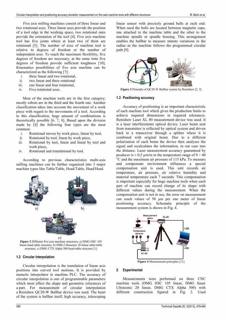
According to previous characteristics multi-axis milling machines can be further organized into 3 major machine types like Table/Table, Head/Table, Head/Head.
Figure 2 Different five axis machine structures: a) DMG HSC 105 linear head-table structure, b) DMG Ultrasonic 20 linear table-table
structure, c) DMG CTX Alpha 500 head-table structure [1] 1.2 Circular interpolation
Circular interpolation is the translation of linear axis
positions into curved tool motions. It is provided by numeric interpolator in machine PLC. The accuracy of circular interpolation is one of programmable parameters which most affect the shape and geometric tolerances of a part. For measurement of circular interpolation a Renishaw QC20-W Ballbar device was used. The heart of the system is ballbar itself, high accuracy, telescoping
linear sensor with precisely ground balls at each end. When used the balls are located between magnetic cups, one attached to the machine table and the other to the machine spindle or spindle housing. This arrangement enables the ballbar to measure minute variations in the radius as the machine follows the programmed circular path [9].
Figure 3 Principle of QC20-W Ballbar system by Renishaw [2, 3]
1.3 Positioning accuracy
Accuracy of positioning is an important characteristic of each machine tool which gives the production limits to achieve required dimensions in required tolerances. Renishaw Laser XL 80 measurement device was used. It is a laser interferometer optical device. Laser beam sent from transmitter is reflected by optical system and driven back to a transceiver through a splitter where it is combined with original beam. Due to a different polarization of each beam the device then analyses the signal and recalculates the information, in our case into the distance. Laser measurement accuracy guaranteed by producer is ± 0,5 µm/m in the temperature range of 0 ÷ 40 °C and the maximum air pressure of 115 kPa. To measure and compensate environment influences a special compensation unit is used. This unit records air temperature, air pressure, air relative humidity and material temperature each 7 seconds. This compensation is important especially for huge machine tools when each part of machine can record change of its shape with different values during the measurement. When the compensation unit is not in use, the error on measurement can reach values of 50 µm per one meter of linear positioning accuracy. Schematic principle of the measurement system is shown in Fig. 4.
Figure 4 Measurement principles [11]
2 Experimental
Measurements were performed on three CNC machine tools (DMG HSC 105 linear, DMG Sauer Ultrasonic 20 linear, DMG CTX Alpha 500) with different construction figured in Fig. 2. Used
480 Technical Gazette 20, 3(2013), 479-484
M. Beňo et al. Mjerenje devijacija točnosti kružne interpolacije i pozicioniranja na petoosnim alatnim strojevima različitih konstrukcija
measurement devices were QC20-W Ballbar system and XL 80 Laser by Renishaw [1].
Measurement conditions for each measurement were as follows: air temperature was 20 °C with deviation of 0,1 °C, air pressure 1003,8 hPa, relative humidity 49 %, compensation coefficient 0,316. 2.1 Positioning accuracy measurement
Measurement was performed in the following
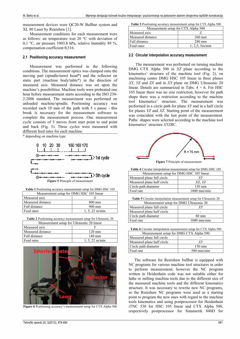
conditions. The measurement optics was clamped onto the moving part (spindle/turret head*) and the reflector on static part (machine body/table*) in the direction of measured axis. Measured distance was set upon the machine’s possibilities. Machine tools were preheated one hour before measurement starts according to the ISO 230-2:2006 standard. The measurement was performed on unloaded machine/spindle. Positioning accuracy was recorded each 10 mm of the path with 5 s pause - this break is necessary for the measurement software to complete the measurement process. One measurement cycle consists of 5 moves from start point to end point and back (Fig. 5). Three cycles were measured with different feed rates for each machine. * depending on machine type
Figure 5 Principle of measurement
Table 1 Positioning accuracy measurement setup for DMG HSC 105
Measurement setup for DMG HSC 105 linear Measured axis X Measured distance 800 mm Full distance 900 mm Feed rates 1, 5, 22 m/min
Table 2 Positioning accuracy measurement setup for Ultrasonic 20
Measurement setup for Ultrasonic 20 linear Measured axis Y Measured distance 120 mm Full distance 140 mm Feed rates 1, 5, 22 m/min
Figure 6 Positioning accuracy’s measurement setup for CTX Alpha 500
Table 3 Positioning accuracy measurement setup for CTX Alpha 500 Measurement setup for CTX Alpha 500
Measured axis Z Measured distance 260 mm Full distance 280 mm Feed rates 1; 2,5; 5m/min
2.2 Circular interpolation accuracy measurement
The measurement was performed on turning machine
DMG CTX Alpha 500 in XZ plane according to the kinematics’ structure of the machine tool (Fig. 2), on machining centre DMG HSC 105 linear in three planes XY, YZ and ZX and in XY plane on DMG Ultrasonic 20 linear. Details are summarized in Tabs. 4 ÷ 6. For HSC 105 linear there was no size restriction, however for path shape there was a restriction according to the machine tool kinematics’ structure. The measurement was performed in a circle path for plane XY and in a half circle for planes YZ and XZ. Starting point of the measurement was coincident with the last point of the measurement. Paths´ shapes were selected according to the machine tool kinematics’ structure XYZBC.
Figure 7 Principle of measurement
Table 4 Circular interpolation measurement setup for DMG HSC 105
Measurement setup for DMG HSC 105 linear Measured plane full circle XY Measured plane half circle XZ, YZ Circle path diameter 150 mm Feed rate 1000 mm/min
Table 5 Circular interpolation measurement setup for Ultrasonic 20
Measurement setup for DMG Ultrasonic 20 Measured plane full circle XY Measured plane half circle - Circle path diameter 80 mm Feed rate 1000 mm/min
Table 6 Circular interpolation measurement setup for CTX Alpha 500
Measurement setup for DMG CTX Alpha 500 Measured plane full circle − Measured plane half circle XY Circle path diameter 150 mm Feed rate 500 mm/min
The software for Renishaw ballbar is equipped with
NC programs for various machine tool structures in order to perform measurement; however the NC program written in Heidenhain code was not suitable either for lathe or milling machine tools due to the different size of the measured machine tools and the different kinematics structure. It was necessary to rewrite new NC programs, so the Renishaw NC programs were used as a starting point to program the new ones with regard to the machine tools kinematics and using postprocessor for Heidenhain iTNC 530 for HSC 105 linear and CTX Alpha 500, respectively postprocessor for Sinumerik 840D for
Tehnički vjesnik 20, 3(2013), 479-484 481

Circular interpolation and positioning accuracy deviation measurement on five axis machine tools with different structures M. Beňo et al.
Ultrasonic 20 linear. Measurement results are summarized in the text that follows.
Figure 8 Circular interpolation’s measurement setup on CTX Alpha 500
3 Measurement results
Results are represented by charts and recorded values
figured in tables. Results are divided into two groups regarding measurement type; machine tools are listed in the same order for both measurement modes. 3.1 Positioning accuracy measurement results
Results are represented by charts shown in Figs. 9 ÷ 11 and adequate Tabs. 7 ÷ 9. These charts show the deviations of positioning for each machine and the repeatability which is represented by the accuracy of machine in reaching the same position from which the movement starts. Measured values are evaluated by Renishaw software for LASER XL 80. The review and comparison with declared values are found in conclusion.
Table 7 Ultrasonic 20 linear measurement results axis Y
Mean Dev. M 0,00172 Reversal B 0,00022 Sys. Dev. E 0,00176 Accuracy A+ 0,001919 Repeat R+ 0,000522 Accuracy A− 0,001887 Repeat R− 0,000358 Acuracy A 0,002037
Table 8 HSC 105 Linear measurement results axis X
Mean Dev. M 4,370 Reversal B 0,100 Sys. Dev. E 4,420 Accuracy A+ 6,728 Repeat R+ 3,162 Accuracy A− 6,866 Repeat R− 3,354 Acuracy A 6,981
Figure 9 Ultrasonic 20 Linear measurement results axis Y
Figure 10 HSC 105 Linear measurement results axis X
Table 9 CTX Alpha measurement results
Mean Dev. M 4,560 Reversal B 1,200 Sys. Dev. E 4,960 Accuracy A+ 5,927 Repeat R+ 1,368 Accuracy A− 5,159 Repeat R− 1,004 Acuracy A 5,927
Figure 11 CTX Alpha measurement results
3.2 Circular interpolation accuracy measurement results
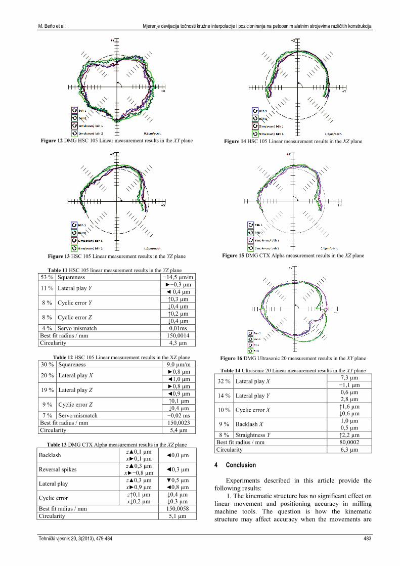
Following charts present circular interpolation
accuracy of measured machine tools according to the measured plane. In Figs. 12 ÷ 16 there is the interpolation accuracy for DMG HSC 105 linear for XY, YZ and XZ plane. Fig. 15 shows interpolation accuracy of Ultrasonic 20 in XY plane and Fig. 16 shows interpolation accuracy of CTX Alpha 500 in XZ plane. Measured values with statistically significant parameters are figured in Tabs. 10 ÷ 14. Measured values were evaluated by Renishaw software for QC20-W ballbar, the review and comparison with declared values can be found in conclusion.
Table 10 HSC 105 Linear measurement results in the XY plane 26 % Relative error 2,7 µm 12 % Straightness Y 1,2 µm
10 % Cyclic error X ↑0,6 µm ↓0,5 µm
10 % Straightness X 1,0 µm
9 % Cyclic error Y ↑0,4 µm ↓0,5 µm
Best fit radius / mm 150,0003 Circularity 3,1 µm
482 Technical Gazette 20, 3(2013), 479-484
M. Beňo et al. Mjerenje devijacija točnosti kružne interpolacije i pozicioniranja na petoosnim alatnim strojevima različitih konstrukcija
Figure 12 DMG HSC 105 Linear measurement results in the XY plane
Figure 13 HSC 105 Linear measurement results in the YZ plane
Table 11 HSC 105 linear measurement results in the YZ plane
53 % Squareness −14,5 µm/m
11 % Lateral play Y ►−0,3 µm ◄ 0,4 µm
8 % Cyclic error Y ↑0,3 µm ↓0,4 µm
8 % Cyclic error Z ↑0,2 µm ↓0,4 µm
4 % Servo mismatch 0,01ms Best fit radius / mm 150,0014 Circularity 4,3 µm
Table 12 HSC 105 Linear measurement results in the XZ plane
30 % Squareness 9,0 µm/m
20 % Lateral play X ►0,8 µm ◄1,0 µm
19 % Lateral play Z ►0,8 µm ◄0,9 µm
9 % Cyclic error Z ↑0,1 µm ↓0,4 µm
7 % Servo mismatch −0,02 ms Best fit radius / mm 150,0023 Circularity 5,4 µm
Table 13 DMG CTX Alpha measurement results in the XZ plane
Backlash z▲0,1 µm x►0,1 µm ◄0,0 µm
Reversal spikes z▲0,3 µm x►−0,8 µm ◄0,3 µm
Lateral play z▲0,3 µm x►0,9 µm
▼0,5 µm ◄0,8 µm
Cyclic error z↑0,1 µm x↓0,2 µm
↓0,4 µm ↓0,3 µm
Best fit radius / mm 150,0058 Circularity 5,1 µm
Figure 14 HSC 105 Linear measurement results in the XZ plane
Figure 15 DMG CTX Alpha measurement results in the XZ plane
Figure 16 DMG Ultrasonic 20 measurement results in the XY plane
Table 14 Ultrasonic 20 Linear measurement results in the XY plane
32 % Lateral play X 7,3 µm −1,1 µm
14 % Lateral play Y 0,6 µm 2,8 µm
10 % Cyclic error X ↑1,6 µm ↓0,6 µm
9 % Backlash X 1,0 µm 0,5 µm
8 % Straightness Y ↑2,2 µm Best fit radius / mm 80,0002 Circularity 6,3 µm
4 Conclusion
Experiments described in this article provide the following results:
1. The kinematic structure has no significant effect on linear movement and positioning accuracy in milling machine tools. The question is how the kinematic structure may affect accuracy when the movements are
Tehnički vjesnik 20, 3(2013), 479-484 483

Circular interpolation and positioning accuracy deviation measurement on five axis machine tools with different structures M. Beňo et al.
combined with the rotational ones. However the measurement device used in this experiment was not able to measure circular paths. This measurement was provided by different measurement devices and the results are described in what follows.
2. Positioning accuracy of machine tools shown in charts (Fig. 6 ÷ Fig. 8) in previous chapter makes it evident that one year operation of machine tools has no significant effect on accuracy of positioning. This statement is based on comparison of measured values with values declared by producer on the certificate of delivery. The maximum values of deviation for milling machine tool Ultrasonic 20 linear was 1,7 µm, declared value for positioning is 5 µm. HSC105 linear deviations maximum measured value was 4,37 µm, declared value 8 µm. The conventional screwbar drive on turning machine declares a value of 10 µm positioning, measured value was 4,56 µm. Declared values were checked according to the standard VDI/DGQ 3441, measurements were taken according to the standard ISO 230-2.
3. Accuracy of repeatability is at a very high level. It is clear from the charts that the deviation of position accuracy has raised with the distance from the start point. Thanks to the fact that each measurement was performed in both up and down direction we can see that the spindle came back to the same position when it started with the accuracy of 0,0002 mm for Ultrasonic 20 machine tool. For HSC 105 linear machine repeatability fell down to the values of 0,0035 mm and for the CTX Alpha machine tool to 0,0013 µm. From the previously mentioned results it is clear that machine drives have negligible effect on machine positioning accuracy, however the construction with two rulers on ultrasonic machine has a visible effect.
4. Circular interpolation of machine tools is in levels accepted by ISO 230-4 standard. Circularity values are as well acceptable.
Results will be used for the next research in circular interpolation and they will be used for machine deviation compensation by including repair coefficient into the machine’s system. Acknowledgements
This article has been realised under the research and development OP for project Centre of Excellence of Five axis Machining Experimental Base for High Tech Research ITMS 26220120045 co-financed by European Fund for Regional Development.
Supporting research activities in Slovakia / Project is
co-financed by European Union. 5 References [1] Kováč, M.; Zvončan, M.; Beňo, M.; Košinár, M.. Laser
interferometry measurement of different structured five axis machine tools positioning accuracy // International Doctoral Seminar Smolenice 2011. Trnava : MTF STU, 2011.
[2] QC20-W ballbar by Renishaw. URL: http://www.atechauthority.com/. (5.10.2011).
[3] QC20-W Ballbar system. URL: http://www.renishaw.com/. (9.10.2011).
[4] Valentovič, E. Stratégia obrábania. Monografia. Bratislava : STU, 2005, p. 152. ISBN 978-80-227-2657-3.
[5] Choi, B.; Jerard, R. Sculptured Surface Machining. Dordrecht : Kluwer Academic Publisher, 1998, p. 368. ISBN 0-412-78020-8.
[6] Bohez, E.; Ariyaujunyya, B.; Sinlapeechewa, C.; Shein, T.; Lap, D.; Belforte, G. Systematic geometric rigid body error identification of 5-axis milling machines. Computer-Aided Design. URL: www.sciencedirect.com/ (6.7.2010).
[7] Bohez, E. L. J. Five-axis milling machine tool kinematic chain design and analysis. // International Journal of Machine Tools & Manufacture, 2001. URL: http://www.sciencedirect.com/science/journal/08906955. (16.8.2010).
[8] Apro, K. Secrets of 5-axis machining. New York : Industrial Press, 2008, p. 173. ISBN 978-0-8311-3375-7.
[9] Košinár, M. Analýza presnosti obrábacieho stroja v rôznych miestach pracovného stola, Žilina: ZU, 2009.
[10] Kováč, M. Technology possiblities of five axis and high speed machining. Trnava : STU, 2011.
[11] XL 80 laser measurement system. URL: http://www.renishaw.com (9.10.2011)
Authors’ addresses Matúš Beňo, Ing. Slovak University of Technology Faculty of Materials Science and Technology Paulinska 16, 91724 Trnava, Slovak Republic +421 918 646 031, [email protected] Martin Kováč, Ing. Slovak University of Technology Faculty of Materials Science and Technology Paulinska 16, 91724 Trnava, Slovak Republic +421 918 646 031, [email protected] Marek Zvončan, Ing. Slovak University of Technology Faculty of Materials Science and Technology Paulinska 16, 91724 Trnava, Slovak Republic +421 918 646 031, [email protected] Jozef Peterka, prof. Dr. Ing. Slovak University of Technology Faculty of Materials Science and Technology Paulinska 16, 91724 Trnava, Slovak Republic +421 918 646 031, [email protected]
484 Technical Gazette 20, 3(2013), 479-484